Embed Size (px)
Citation preview
Modicon M580
QGH60283 09/2020
QG
H60
283.
06
www.schneider-electric.com
Modicon M580Safety System Planning GuideOriginal instructions
09/2020
The information provided in this documentation contains general descriptions and/or technical characteristics of the performance of the products contained herein. This documentation is not intended as a substitute for and is not to be used for determining suitability or reliability of these products for specific user applications. It is the duty of any such user or integrator to perform the appropriate and complete risk analysis, evaluation and testing of the products with respect to the relevant specific application or use thereof. Neither Schneider Electric nor any of its affiliates or subsidiaries shall be responsible or liable for misuse of the information contained herein. If you have any suggestions for improvements or amendments or have found errors in this publication, please notify us. You agree not to reproduce, other than for your own personal, noncommercial use, all or part of this document on any medium whatsoever without permission of Schneider Electric, given in writing. You also agree not to establish any hypertext links to this document or its content. Schneider Electric does not grant any right or license for the personal and noncommercial use of the document or its content, except for a non-exclusive license to consult it on an "as is" basis, at your own risk. All other rights are reserved.All pertinent state, regional, and local safety regulations must be observed when installing and using this product. For reasons of safety and to help ensure compliance with documented system data, only the manufacturer should perform repairs to components.When devices are used for applications with technical safety requirements, the relevant instructions must be followed. Failure to use Schneider Electric software or approved software with our hardware products may result in injury, harm, or improper operating results.Failure to observe this information can result in injury or equipment damage.© 2020 Schneider Electric. All rights reserved.
2 QGH60283 09/2020
Table of Contents
Safety Information. . . . . . . . . . . . . . . . . . . . . . . . . . . . . . 7About the Book . . . . . . . . . . . . . . . . . . . . . . . . . . . . . . . . 11
Chapter 1 M580 Safety System Supported Modules . . . . . . . . . . . 15M580 Safety System Certified Modules . . . . . . . . . . . . . . . . . . . . . . . 16Non-Interfering Modules . . . . . . . . . . . . . . . . . . . . . . . . . . . . . . . . . . . 17
Chapter 2 Selecting an M580 Safety System Topology . . . . . . . . . 21Designing an M580 Safety System Topology . . . . . . . . . . . . . . . . . . . 22M580 Safety Topologies . . . . . . . . . . . . . . . . . . . . . . . . . . . . . . . . . . . 25
Chapter 3 M580 Safety CPU and Coprocessor. . . . . . . . . . . . . . . . 313.1 M580 Safety CPU & Coprocessor Physical Features . . . . . . . . . . . . . 32
Physical Description of the M580 Safety CPU & Coprocessor . . . . . . 33LED Displays for the M580 Safety CPU and Copro . . . . . . . . . . . . . . 38Ethernet Ports . . . . . . . . . . . . . . . . . . . . . . . . . . . . . . . . . . . . . . . . . . . 40USB Port . . . . . . . . . . . . . . . . . . . . . . . . . . . . . . . . . . . . . . . . . . . . . . . 43SFP Socket . . . . . . . . . . . . . . . . . . . . . . . . . . . . . . . . . . . . . . . . . . . . . 45SD Memory Card. . . . . . . . . . . . . . . . . . . . . . . . . . . . . . . . . . . . . . . . . 46
3.2 M580 Safety CPU & Coprocessor Performance Characteristics. . . . . 48M580 CPU & Copro Performance Characteristics . . . . . . . . . . . . . . . 48
Chapter 4 M580 Safety Power Supplies . . . . . . . . . . . . . . . . . . . . . 51Physical Description of the M580 Safety Power Supplies . . . . . . . . . . 52M580 Safety Power Supply Performance Characteristics. . . . . . . . . . 57M580 Safety Power Supply Alarm Relay. . . . . . . . . . . . . . . . . . . . . . . 62
Chapter 5 M580 Safety I/O Modules . . . . . . . . . . . . . . . . . . . . . . . . 635.1 M580 Safety I/O Modules Physical Description. . . . . . . . . . . . . . . . . . 64
Physical Description of M580 I/O Modules . . . . . . . . . . . . . . . . . . . . . 645.2 M580 Safety I/O Performance Characteristics . . . . . . . . . . . . . . . . . . 70
BMXSAI0410 Safety Analog Input Module Performance Characteristics. . . . . . . . . . . . . . . . . . . . . . . . . . . . . . . . . . . . . . . . . . . 71BMXSDI1602 Safety Digital Input Module Performance Characteristics 73BMXSDO0802 Safety Digital Output Module Performance Characteristics. . . . . . . . . . . . . . . . . . . . . . . . . . . . . . . . . . . . . . . . . . . 75BMXSRA0405 Safety Digital Relay Output Module . . . . . . . . . . . . . . 77
QGH60283 09/2020 3
Chapter 6 Installing the M580 Safety PAC . . . . . . . . . . . . . . . . . . . . 796.1 Installing M580 Racks and Extender Modules . . . . . . . . . . . . . . . . . . . 80
Planning the Installation of the Local Rack . . . . . . . . . . . . . . . . . . . . . 81Mounting the Racks . . . . . . . . . . . . . . . . . . . . . . . . . . . . . . . . . . . . . . . 86Extending a Rack . . . . . . . . . . . . . . . . . . . . . . . . . . . . . . . . . . . . . . . . . 88
6.2 Installing M580 CPU, Copro, Power Supply, and I/O. . . . . . . . . . . . . . 89Installing the CPU and Coprocessor . . . . . . . . . . . . . . . . . . . . . . . . . . 90Installing a Power Supply Module . . . . . . . . . . . . . . . . . . . . . . . . . . . . 93Installing M580 Safety I/O . . . . . . . . . . . . . . . . . . . . . . . . . . . . . . . . . . 97Installing an SD Memory Card in a CPU . . . . . . . . . . . . . . . . . . . . . . . 99
Chapter 7 Upgrading M580 Safety CPU Firmware . . . . . . . . . . . . . . 101Firmware Update with Automation Device Maintenance . . . . . . . . . . . 102Upgrading CPU Firmware with Unity Loader . . . . . . . . . . . . . . . . . . . . 103
Chapter 8 Operating an M580 Safety System. . . . . . . . . . . . . . . . . . 1058.1 Process, Safety and Global Data Areas in Control Expert. . . . . . . . . . 106
Data Separation in Control Expert . . . . . . . . . . . . . . . . . . . . . . . . . . . . 1068.2 Operating Modes, Operating States, and Tasks . . . . . . . . . . . . . . . . . 109
M580 Safety PAC Operating Modes . . . . . . . . . . . . . . . . . . . . . . . . . . 110M580 Safety PAC Operating States. . . . . . . . . . . . . . . . . . . . . . . . . . . 115Start Up Sequences . . . . . . . . . . . . . . . . . . . . . . . . . . . . . . . . . . . . . . . 120M580 Safety PAC Tasks . . . . . . . . . . . . . . . . . . . . . . . . . . . . . . . . . . . 124
8.3 Building an M580 Safety Project . . . . . . . . . . . . . . . . . . . . . . . . . . . . . 127Building an M580 Safety Project . . . . . . . . . . . . . . . . . . . . . . . . . . . . . 128Safe Signature . . . . . . . . . . . . . . . . . . . . . . . . . . . . . . . . . . . . . . . . . . . 129
8.4 Locking M580 Safety I/O Module Configurations. . . . . . . . . . . . . . . . . 136Locking M580 Safety I/O Module Configurations. . . . . . . . . . . . . . . . . 136
8.5 Initializing Data in Control Expert . . . . . . . . . . . . . . . . . . . . . . . . . . . . . 139Initializing Data in Control Expert for the M580 Safety PAC . . . . . . . . 139
8.6 Working with Animation Tables in Control Expert . . . . . . . . . . . . . . . . 140Animation Tables and Operator Screens . . . . . . . . . . . . . . . . . . . . . . . 140
8.7 Adding Code Sections . . . . . . . . . . . . . . . . . . . . . . . . . . . . . . . . . . . . . 144Adding Code to an M580 Safety Project . . . . . . . . . . . . . . . . . . . . . . . 145Diagnostic Request . . . . . . . . . . . . . . . . . . . . . . . . . . . . . . . . . . . . . . . 149Swap and Clear Commands . . . . . . . . . . . . . . . . . . . . . . . . . . . . . . . . 152
4 QGH60283 09/2020
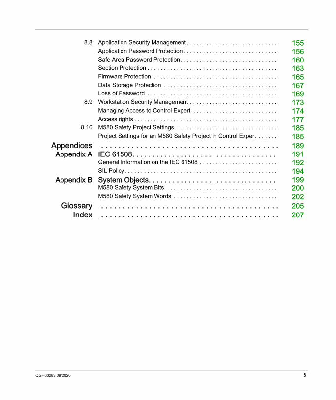
8.8 Application Security Management . . . . . . . . . . . . . . . . . . . . . . . . . . . . 155Application Password Protection . . . . . . . . . . . . . . . . . . . . . . . . . . . . . 156Safe Area Password Protection. . . . . . . . . . . . . . . . . . . . . . . . . . . . . . 160Section Protection . . . . . . . . . . . . . . . . . . . . . . . . . . . . . . . . . . . . . . . . 163Firmware Protection . . . . . . . . . . . . . . . . . . . . . . . . . . . . . . . . . . . . . . 165Data Storage Protection . . . . . . . . . . . . . . . . . . . . . . . . . . . . . . . . . . . 167Loss of Password . . . . . . . . . . . . . . . . . . . . . . . . . . . . . . . . . . . . . . . . 169
8.9 Workstation Security Management . . . . . . . . . . . . . . . . . . . . . . . . . . . 173Managing Access to Control Expert . . . . . . . . . . . . . . . . . . . . . . . . . . 174Access rights . . . . . . . . . . . . . . . . . . . . . . . . . . . . . . . . . . . . . . . . . . . . 177
8.10 M580 Safety Project Settings . . . . . . . . . . . . . . . . . . . . . . . . . . . . . . . 185Project Settings for an M580 Safety Project in Control Expert . . . . . . 185
Appendices . . . . . . . . . . . . . . . . . . . . . . . . . . . . . . . . . . . . . . . . . 189Appendix A IEC 61508. . . . . . . . . . . . . . . . . . . . . . . . . . . . . . . . . . . . 191
General Information on the IEC 61508 . . . . . . . . . . . . . . . . . . . . . . . . 192SIL Policy. . . . . . . . . . . . . . . . . . . . . . . . . . . . . . . . . . . . . . . . . . . . . . . 194
Appendix B System Objects. . . . . . . . . . . . . . . . . . . . . . . . . . . . . . . . 199M580 Safety System Bits . . . . . . . . . . . . . . . . . . . . . . . . . . . . . . . . . . 200M580 Safety System Words . . . . . . . . . . . . . . . . . . . . . . . . . . . . . . . . 202
Glossary . . . . . . . . . . . . . . . . . . . . . . . . . . . . . . . . . . . . . . . . . 205Index . . . . . . . . . . . . . . . . . . . . . . . . . . . . . . . . . . . . . . . . . 207
QGH60283 09/2020 5

6 QGH60283 09/2020
Safety Information
Important Information
NOTICERead these instructions carefully, and look at the equipment to become familiar with the device before trying to install, operate, service, or maintain it. The following special messages may appear throughout this documentation or on the equipment to warn of potential hazards or to call attention to information that clarifies or simplifies a procedure.
QGH60283 09/2020 7
PLEASE NOTEElectrical equipment should be installed, operated, serviced, and maintained only by qualified personnel. No responsibility is assumed by Schneider Electric for any consequences arising out of the use of this material.A qualified person is one who has skills and knowledge related to the construction and operation of electrical equipment and its installation, and has received safety training to recognize and avoid the hazards involved.
BEFORE YOU BEGINDo not use this product on machinery lacking effective point-of-operation guarding. Lack of effective point-of-operation guarding on a machine can result in serious injury to the operator of that machine.
This automation equipment and related software is used to control a variety of industrial processes. The type or model of automation equipment suitable for each application will vary depending on factors such as the control function required, degree of protection required, production methods, unusual conditions, government regulations, etc. In some applications, more than one processor may be required, as when backup redundancy is needed.Only you, the user, machine builder or system integrator can be aware of all the conditions and factors present during setup, operation, and maintenance of the machine and, therefore, can determine the automation equipment and the related safeties and interlocks which can be properly used. When selecting automation and control equipment and related software for a particular application, you should refer to the applicable local and national standards and regulations. The National Safety Council's Accident Prevention Manual (nationally recognized in the United States of America) also provides much useful information.In some applications, such as packaging machinery, additional operator protection such as point-of-operation guarding must be provided. This is necessary if the operator's hands and other parts of the body are free to enter the pinch points or other hazardous areas and serious injury can occur. Software products alone cannot protect an operator from injury. For this reason the software cannot be substituted for or take the place of point-of-operation protection.
WARNINGUNGUARDED EQUIPMENT Do not use this software and related automation equipment on equipment which does not have
point-of-operation protection. Do not reach into machinery during operation.Failure to follow these instructions can result in death, serious injury, or equipment damage.
8 QGH60283 09/2020
Ensure that appropriate safeties and mechanical/electrical interlocks related to point-of-operation protection have been installed and are operational before placing the equipment into service. All interlocks and safeties related to point-of-operation protection must be coordinated with the related automation equipment and software programming.NOTE: Coordination of safeties and mechanical/electrical interlocks for point-of-operation protection is outside the scope of the Function Block Library, System User Guide, or other implementation referenced in this documentation.
START-UP AND TESTBefore using electrical control and automation equipment for regular operation after installation, the system should be given a start-up test by qualified personnel to verify correct operation of the equipment. It is important that arrangements for such a check be made and that enough time is allowed to perform complete and satisfactory testing.
Follow all start-up tests recommended in the equipment documentation. Store all equipment documentation for future references.Software testing must be done in both simulated and real environments.Verify that the completed system is free from all short circuits and temporary grounds that are not installed according to local regulations (according to the National Electrical Code in the U.S.A, for instance). If high-potential voltage testing is necessary, follow recommendations in equipment documentation to prevent accidental equipment damage.Before energizing equipment: Remove tools, meters, and debris from equipment. Close the equipment enclosure door. Remove all temporary grounds from incoming power lines. Perform all start-up tests recommended by the manufacturer.
WARNINGEQUIPMENT OPERATION HAZARD Verify that all installation and set up procedures have been completed. Before operational tests are performed, remove all blocks or other temporary holding means
used for shipment from all component devices. Remove tools, meters, and debris from equipment.Failure to follow these instructions can result in death, serious injury, or equipment damage.
QGH60283 09/2020 9
OPERATION AND ADJUSTMENTSThe following precautions are from the NEMA Standards Publication ICS 7.1-1995 (English version prevails): Regardless of the care exercised in the design and manufacture of equipment or in the selection
and ratings of components, there are hazards that can be encountered if such equipment is improperly operated.
It is sometimes possible to misadjust the equipment and thus produce unsatisfactory or unsafe operation. Always use the manufacturer’s instructions as a guide for functional adjustments. Personnel who have access to these adjustments should be familiar with the equipment manufacturer’s instructions and the machinery used with the electrical equipment.
Only those operational adjustments actually required by the operator should be accessible to the operator. Access to other controls should be restricted to prevent unauthorized changes in operating characteristics.
10 QGH60283 09/2020
About the Book
At a Glance
Document ScopeThis Safety System Planning Guide describes the modules of the M580 Safety system with special regard to how they meet the Safety requirements of the IEC 61508. It provides detailed information on how to install, run, and maintain the system correctly in order to help protect human beings as well as to help prevent damage to environment, equipment, and production.This documentation is intended for qualified personnel familiar with Functional Safety and Control Expert XL Safety. Commissioning and operating the M580 Safety System may only be performed by persons who are authorized to commission and operate systems in accordance with established Functional Safety standards.
Validity NoteThis document is valid for EcoStruxure™ Control Expert 15.0 or later.For product compliance and environmental information (RoHS, REACH, PEP, EOLI, etc.), go to www.schneider-electric.com/green-premium.The technical characteristics of the devices described in the present document also appear online. To access the information online:
The characteristics that are described in the present document should be the same as those characteristics that appear online. In line with our policy of constant improvement, we may revise content over time to improve clarity and accuracy. If you see a difference between the document and online information, use the online information as your reference.
Step Action1 Go to the Schneider Electric home page www.schneider-electric.com.2 In the Search box type the reference of a product or the name of a product range.
Do not include blank spaces in the reference or product range. To get information on grouping similar modules, use asterisks (*).
3 If you entered a reference, go to the Product Datasheets search results and click on the reference that interests you.If you entered the name of a product range, go to the Product Ranges search results and click on the product range that interests you.
4 If more than one reference appears in the Products search results, click on the reference that interests you.
5 Depending on the size of your screen, you may need to scroll down to see the datasheet.6 To save or print a datasheet as a .pdf file, click Download XXX product datasheet.
QGH60283 09/2020 11
Related Documents
Title of documentation Reference numberModicon M580, Safety Manual QGH46982 (English),
QGH46983 (French), QGH46984 (German), QGH46985 (Italian), QGH46986 (Spanish), QGH46987 (Chinese)
EcoStruxure™ Control Expert, Safety, Block Library QGH60275 (English), QGH60278 (French), QGH60279 (German), QGH60280 (Italian), QGH60281 (Spanish), QGH60282 (Chinese)
Modicon Controllers Platform Cyber Security, Reference Manual
EIO0000001999 (English), EIO0000002001 (French), EIO0000002000 (German), EIO0000002002 (Italian), EIO0000002003 (Spanish), EIO0000002004 (Chinese)
Modicon M580, Hardware, Reference Manual EIO0000001578 (English), EIO0000001579 (French), EIO0000001580 (German), EIO0000001582 (Italian), EIO0000001581 (Spanish), EIO0000001583 (Chinese)
Modicon M580 Standalone, System Planning Guide for Frequently Used Architectures
HRB62666 (English), HRB65318 (French), HRB65319 (German), HRB65320 (Italian), HRB65321 (Spanish), HRB65322 (Chinese)
Modicon M580, System Planning Guide for Complex Topologies
NHA58892 (English), NHA58893 (French), NHA58894 (German), NHA58895 (Italian), NHA58896 (Spanish), NHA58897 (Chjnese)
Modicon M580 Hot Standby, System Planning Guide for Frequently Used Architectures
NHA58880 (English), NHA58881 (French), NHA58882 (German), NHA58883 (Italian), NHA58884 (Spanish), NHA58885 (Chinese)
12 QGH60283 09/2020
You can download these technical publications and other technical information from our website at www.schneider-electric.com/en/download.
EcoStruxure™ Automation Device Maintenance, User Guide
EIO0000004033 (English), EIO0000004048 (French), EIO0000004046 (German), EIO0000004049 (Italian), EIO0000004047 (Spanish), EIO0000004050 (Chinese)
Unity Loader, User Guide 33003805 (English), 33003806 (French), 33003807 (German), 33003809 (Italian), 33003808 (Spanish), 33003810 (Chinese)
EcoStruxure™ Control Expert, Operating Modes 33003101 (English), 33003102 (French), 33003103 (German), 33003104 (Spanish), 33003696 (Italian), 33003697 (Chinese)
EcoStruxure™ Control Expert, System Bits and Words, Reference Manual
EIO0000002135 (English), EIO0000002136 (French), EIO0000002137 (German), EIO0000002138 (Italian), EIO0000002139 (Spanish), EIO0000002140 (Chinese)
Title of documentation Reference number
QGH60283 09/2020 13

14 QGH60283 09/2020
Modicon M580Supported modulesQGH60283 09/2020
M580 Safety System Supported Modules
Chapter 1M580 Safety System Supported Modules
IntroductionAn M580 safety project can include both safety modules and non-safety modules. You can use: Safety modules in the SAFE task. Non-safety modules only for the non-safe tasks (MAST, FAST, AUX0, and AUX1).
NOTE: Only non-safety modules that do not interfere with the safety function can be added to a safety project.
Use only the Control Expert programming software of Schneider Electric for programming, commissioning, and operating your M580 safety application. Control Expert L Safety provides all the functionality of Control Expert L and can be used with
BMEP582040S and BMEH582040S safety CPUs. Control Expert XL Safety provides all the functionality of Control Expert XL and can be used for
the entire range of BMEP58•040S and BMEH58•040S safety CPUs.This chapter lists the safety and non-safety modules supported by the M580 safety system.
What Is in This Chapter?This chapter contains the following topics:
Topic PageM580 Safety System Certified Modules 16Non-Interfering Modules 17
QGH60283 09/2020 15
Supported modules
M580 Safety System Certified Modules
Certified ModulesThe M580 safety PAC is a safety-related system certified by TÜV Rheinland Group, according to: SIL3/IEC 61508/IEC 61511 SIL CL3/IEC 62061 PLe, Cat. 4 / ISO 13849-1 CIP Safety IEC 61784-3It is based on the M580 family of programmable automation controllers (PACs). The following Schneider Electric M580 safety modules are certified: BMEP584040S standalone CPU BMEP582040S standalone CPU BMEH582040S Hot Standby CPU BMEH584040S Hot Standby CPU BMEH586040S Hot Standby CPU BMEP58CPROS3 co-processor BMXSAI0410 analog input module BMXSDI1602 digital input module BMXSDO0802 digital output module BMXSRA0405 digital relay output module BMXCPS4002S power supply BMXCPS4022S power supply BMXCPS3522S power supplyNOTE: In addition to the safety modules listed above, you can also include non-interfering, non-safety modules (see page 17) in your safety project.You can find the most recent information on the certified product versions on the TÜV Rheinland Group website: www.certipedia.com or www.fs-products.com.
Replacing a CPUIt is possible to replace a BME•58•040S CPU with another BME•58•040S. However, the replacement does not work if the following limitations are exceeded : number of I/O number of I/O drops number of variables application memory sizeRefer to the topics: Configuration Compatibility in the Modicon M580 Hot Standby System Planning Guide for
Frequently Used Architectures for a description of Control Expert applications that are compatible with safety and Hot Standby CPUs.
M580 CPU & Copro Performance Characteristics (see page 48) in the Modicon M580 Safety System Planning Guide for a description of CPU limitations.
16 QGH60283 09/2020
Supported modules
Non-Interfering Modules
IntroductionAn M580 safety project can include both safety modules and non-safety modules. You can use non-safety modules only for non-safe tasks. Only non-safety modules that do not interfere with the safety function can be added to a safety project.
Definition of a Non-Interfering Module
A non-interfering module is a module which cannot interfere with the safety function. For in-rack M580 modules (BMEx, BMXx, PMXx, and PMEx), there are two types of non-interfering modules: Type 1: A type 1 module can be installed in the same rack as safety modules (wherever the
safety module is placed, in the main or extension rack). Type 2: A type 2 non-interfering module cannot be installed in the same main rack as safety
modules (wherever the safety module is placed, in the main or extension rack). NOTE: Type 1 and Type 2 modules are listed on TÜV Rheinland website at https://fs-products.tuvasi.com.For not in-rack Mx80 modules, all Ethernet equipment (DIO or DRS) can be considered as non-interfering, and therefore can be used as part of an M580 safety system.
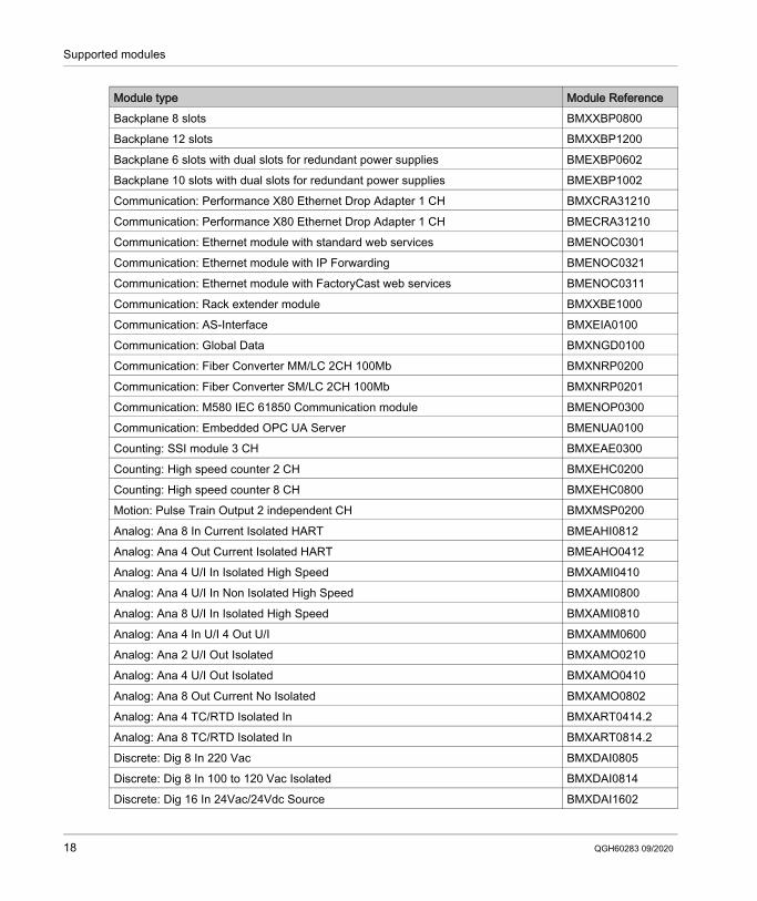
Type 1 Non-Interfering Modules for SIL3 ApplicationsThe following non-safety modules can qualify as type-1 non-interfering modules in an M580 safety system.NOTE: The list of type-1 non-interfering non-safety modules may change from time to time. For the current list, visit the TÜV Rheinland website at https://fs-products.tuvasi.com.
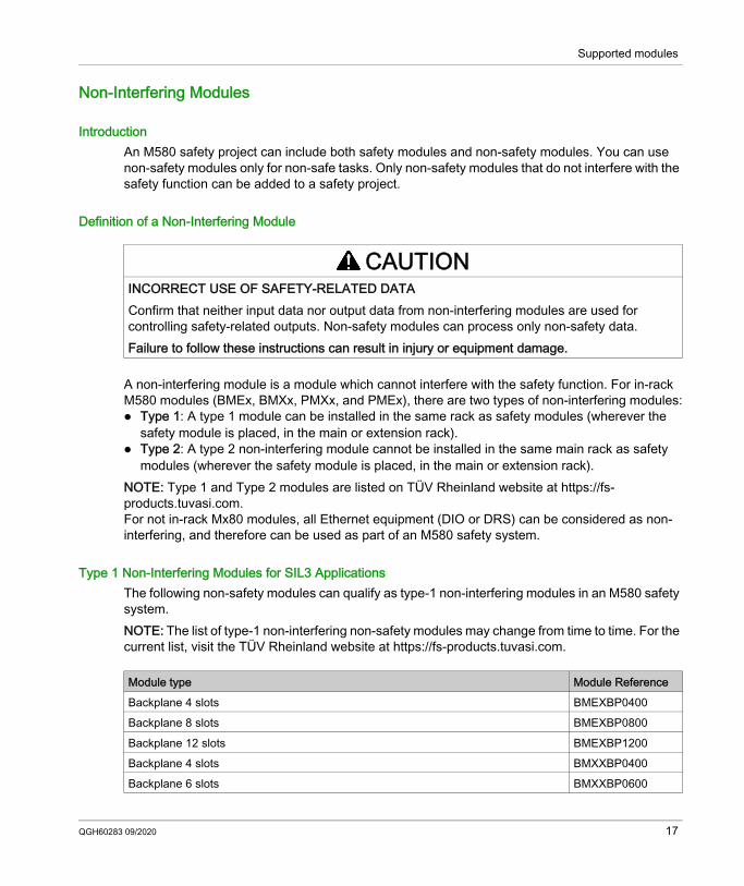
CAUTIONINCORRECT USE OF SAFETY-RELATED DATAConfirm that neither input data nor output data from non-interfering modules are used for controlling safety-related outputs. Non-safety modules can process only non-safety data.Failure to follow these instructions can result in injury or equipment damage.
Module type Module ReferenceBackplane 4 slots BMEXBP0400Backplane 8 slots BMEXBP0800Backplane 12 slots BMEXBP1200Backplane 4 slots BMXXBP0400Backplane 6 slots BMXXBP0600
QGH60283 09/2020 17
Supported modules
Backplane 8 slots BMXXBP0800Backplane 12 slots BMXXBP1200Backplane 6 slots with dual slots for redundant power supplies BMEXBP0602Backplane 10 slots with dual slots for redundant power supplies BMEXBP1002Communication: Performance X80 Ethernet Drop Adapter 1 CH BMXCRA31210Communication: Performance X80 Ethernet Drop Adapter 1 CH BMECRA31210Communication: Ethernet module with standard web services BMENOC0301Communication: Ethernet module with IP Forwarding BMENOC0321Communication: Ethernet module with FactoryCast web services BMENOC0311Communication: Rack extender module BMXXBE1000Communication: AS-Interface BMXEIA0100Communication: Global Data BMXNGD0100Communication: Fiber Converter MM/LC 2CH 100Mb BMXNRP0200Communication: Fiber Converter SM/LC 2CH 100Mb BMXNRP0201Communication: M580 IEC 61850 Communication module BMENOP0300Communication: Embedded OPC UA Server BMENUA0100Counting: SSI module 3 CH BMXEAE0300Counting: High speed counter 2 CH BMXEHC0200Counting: High speed counter 8 CH BMXEHC0800Motion: Pulse Train Output 2 independent CH BMXMSP0200Analog: Ana 8 In Current Isolated HART BMEAHI0812Analog: Ana 4 Out Current Isolated HART BMEAHO0412Analog: Ana 4 U/I In Isolated High Speed BMXAMI0410Analog: Ana 4 U/I In Non Isolated High Speed BMXAMI0800Analog: Ana 8 U/I In Isolated High Speed BMXAMI0810Analog: Ana 4 In U/I 4 Out U/I BMXAMM0600Analog: Ana 2 U/I Out Isolated BMXAMO0210Analog: Ana 4 U/I Out Isolated BMXAMO0410Analog: Ana 8 Out Current No Isolated BMXAMO0802Analog: Ana 4 TC/RTD Isolated In BMXART0414.2Analog: Ana 8 TC/RTD Isolated In BMXART0814.2Discrete: Dig 8 In 220 Vac BMXDAI0805Discrete: Dig 8 In 100 to 120 Vac Isolated BMXDAI0814Discrete: Dig 16 In 24Vac/24Vdc Source BMXDAI1602
Module type Module Reference
18 QGH60283 09/2020
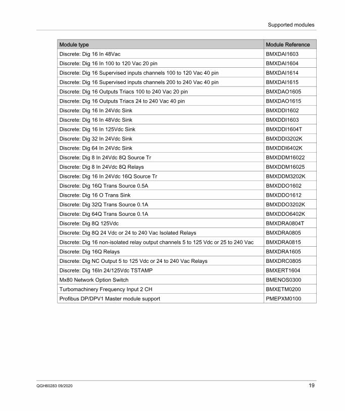
Supported modules
Discrete: Dig 16 In 48Vac BMXDAI1603Discrete: Dig 16 In 100 to 120 Vac 20 pin BMXDAI1604Discrete: Dig 16 Supervised inputs channels 100 to 120 Vac 40 pin BMXDAI1614Discrete: Dig 16 Supervised inputs channels 200 to 240 Vac 40 pin BMXDAI1615Discrete: Dig 16 Outputs Triacs 100 to 240 Vac 20 pin BMXDAO1605Discrete: Dig 16 Outputs Triacs 24 to 240 Vac 40 pin BMXDAO1615Discrete: Dig 16 In 24Vdc Sink BMXDDI1602Discrete: Dig 16 In 48Vdc Sink BMXDDI1603Discrete: Dig 16 In 125Vdc Sink BMXDDI1604TDiscrete: Dig 32 In 24Vdc Sink BMXDDI3202KDiscrete: Dig 64 In 24Vdc Sink BMXDDI6402KDiscrete: Dig 8 In 24Vdc 8Q Source Tr BMXDDM16022Discrete: Dig 8 In 24Vdc 8Q Relays BMXDDM16025Discrete: Dig 16 In 24Vdc 16Q Source Tr BMXDDM3202KDiscrete: Dig 16Q Trans Source 0.5A BMXDDO1602Discrete: Dig 16 O Trans Sink BMXDDO1612Discrete: Dig 32Q Trans Source 0.1A BMXDDO3202KDiscrete: Dig 64Q Trans Source 0.1A BMXDDO6402KDiscrete: Dig 8Q 125Vdc BMXDRA0804TDiscrete: Dig 8Q 24 Vdc or 24 to 240 Vac Isolated Relays BMXDRA0805Discrete: Dig 16 non-isolated relay output channels 5 to 125 Vdc or 25 to 240 Vac BMXDRA0815Discrete: Dig 16Q Relays BMXDRA1605Discrete: Dig NC Output 5 to 125 Vdc or 24 to 240 Vac Relays BMXDRC0805Discrete: Dig 16In 24/125Vdc TSTAMP BMXERT1604Mx80 Network Option Switch BMENOS0300Turbomachinery Frequency Input 2 CH BMXETM0200Profibus DP/DPV1 Master module support PMEPXM0100
Module type Module Reference
QGH60283 09/2020 19
Supported modules
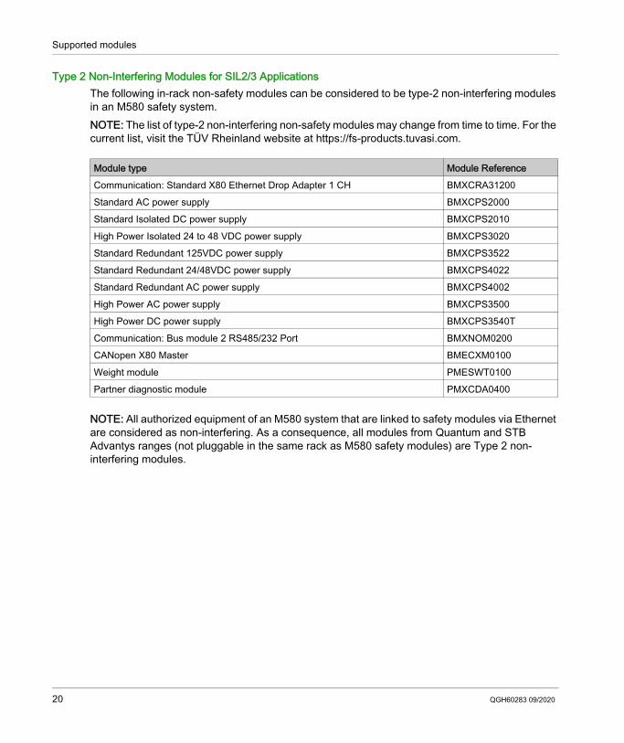
Type 2 Non-Interfering Modules for SIL2/3 ApplicationsThe following in-rack non-safety modules can be considered to be type-2 non-interfering modules in an M580 safety system.NOTE: The list of type-2 non-interfering non-safety modules may change from time to time. For the current list, visit the TÜV Rheinland website at https://fs-products.tuvasi.com.
NOTE: All authorized equipment of an M580 system that are linked to safety modules via Ethernet are considered as non-interfering. As a consequence, all modules from Quantum and STB Advantys ranges (not pluggable in the same rack as M580 safety modules) are Type 2 non-interfering modules.
Module type Module ReferenceCommunication: Standard X80 Ethernet Drop Adapter 1 CH BMXCRA31200Standard AC power supply BMXCPS2000Standard Isolated DC power supply BMXCPS2010High Power Isolated 24 to 48 VDC power supply BMXCPS3020Standard Redundant 125VDC power supply BMXCPS3522Standard Redundant 24/48VDC power supply BMXCPS4022Standard Redundant AC power supply BMXCPS4002High Power AC power supply BMXCPS3500High Power DC power supply BMXCPS3540TCommunication: Bus module 2 RS485/232 Port BMXNOM0200CANopen X80 Master BMECXM0100Weight module PMESWT0100Partner diagnostic module PMXCDA0400
20 QGH60283 09/2020
Modicon M580Selecting a TopologyQGH60283 09/2020
Selecting an M580 Safety System Topology
Chapter 2Selecting an M580 Safety System Topology
IntroductionThis chapter describes the topologies supported by an M580 safety system.
What Is in This Chapter?This chapter contains the following topics:
Topic PageDesigning an M580 Safety System Topology 22M580 Safety Topologies 25
QGH60283 09/2020 21
Selecting a Topology
Designing an M580 Safety System Topology
Support for Standalone and Hot Standby PACsAn M580 safety system supports SIL3 applications for standalone and Hot Standby PACs. Each CPU rack includes a CPU and a coprocessor module.NOTE: For a description of available racks and their permitted usage refer to the topic Rack Usage (see page 81).
Placing Safety Modules in the RIO Main RingInstall M580 safety modules only in the RIO main ring, which includes: The local main rack. Standalone safety PACs can also include up to seven optional local
extended racks. The local main rack must include a safety power supply, a safety CPU, and a safety
coprocessor. For a standalone safety PAC, the local main rack and the local extended racks may also
include safety I/O. An M580 Hot Standby PAC does not support I/O on the local main rack, or local extended racks.
NOTE: The maximum distance between the main rack and the last extended rack is 30 m. Up to 31 RIO drops for the BMEH586040S Hot Standby CPU (16 RIO drops for the
BME•584040S CPU; 8 RIO drops for the BME•582040S CPU), each consisting of a remote main rack and an optional remote extended rack.
Any rack with safety modules also requires a safety power supply.NOTE: A rack that includes safety modules may also include type 1 non-interfering modules (see page 17). However, type 2 non-interfering modules (see page 20) may not be placed on the same rack as safety modules. Type 2 non-interfering modules may be placed on racks without safety modules–for example, in racks of distributed equipment. Other non-safe modules may not be included in an M580 safety system.
Extending a Main RackUse BMXXBE1000 rack extender modules to daisy chain together main and extended racks. Connect each pair of extender modules using BMXXBC•••K connector cables, and terminate each end of the chain with TSXELYEX line terminators.
22 QGH60283 09/2020
Selecting a Topology
Local Rack Communications with an RIO DropTo support RIO drops in an M580 safety system with CPU firmware 3.10 or earlier, configure the M580 safety CPU as an NTP server, or as an NTP client (with another device configured as an NTP server). Without a properly set up clock (NTP), safety I/O communication may not operate correctly. Use a BM•CRA312•0 remote adapter module (a BM•CRA31200 for a remote rack hosting Non Interfering only modules, and a BM•CRA31210 adapter for remote rack hosting both non-interfering and/or safety I/O modules to connect the RIO drop to the RIO main ring. Connect each end of the RIO main ring to the two dual ports on the BME•58•040S safety CPU.If the connection is made via Cat5e copper cable, the maximum distance between drops is 100 m.NOTE: Alternatively, you can connect the local main rack to the BM•CRA312•0 remote adapter in the RIO drop by placing a BMXNRP020• fiber optic repeater module into each rack. Refer to the topic Using Fiber Converter Modules in the Modicon M580 Standalone System Planning Guide for Frequently Used Architectures for additional information.
Connecting Two M580 Safety PACsA M580 safety system also supports peer-to-peer black channel communication between two safety PACs. Typically, this connection is made via a BMENOC0321 in each safety system. Refer to the peer-to-peer communications topic in the Modicon M580 Safety Manual for more information.NOTE: To support black channel communications between two PACs with CPU firmware 3.10 or earlier, enable the NTP service in both PACs. You can configure one PAC as the NTP server, and the other as the NTP client. Alternatively, you can configure each PAC as an NTP client, with another device configured as NTP server.
Adding Distributed Equipment to an M580 Safety SystemYou can include distributed equipment in your M580 safety system. Typically, distributed equipment is connected as either non-looping daisy chain, or a daisy chain loop.You can connect a distributed equipment daisy chain loop to the two network ports of one of the following modules on the RIO main ring: a BMENOC0301/11 Ethernet communications module. a BMENOS0300 Ethernet network option switch. a ConneXium dual ring switch.You can also use the service port of a BMENOC0301/11 Ethernet communications module, a BMENOS0300 Ethernet network option switch or the BME•58•040S safety CPU to connect distributed equipment in the shape of a non-looping daisy chain.NOTE: Place only type 1 and type 2 non-interfering modules in a distributed equipment network. Place safety modules only in the local rack (main or extended) and the RIO network. Exclude non-safe modules that are not type 1 or type 2 non-interfering modules from your safety project.
QGH60283 09/2020 23
Selecting a Topology
Refer to the topic Selecting the Correct Topology in the Modicon M580 Standalone System Planning Guide for Frequently Used Architectures for additional information on connecting distributed equipment to an M580 CPU.
Adding CIP Safety Equipment to the M580 Safety SystemYou can include CIP Safety I/O (CSIO) devices in your M580 safety system as CSIO distributed equipment.You can connect CSIO distributed equipment to the RIO main ring through: the service port of a CPU or a BM•CRA31210 X80 EIO adapter module. a BMENOS0300 Ethernet network option switch. a ConneXium Dual Ring Switch (DRS).Each type of I/O (CSIO, RIO, DIO) has its own limitation. To maintain an acceptable level of performance, it is recommended not to use the maximum of all I/O types in the same architecture. It is recommended that a typical M580 CIP Safety architecture is based on a remote or distributed topology. Recommended limitations are listed in table below:
The CSIO time contribution to the SAFE task is roughly 100 µs/equipment with a BMEP584040S CPU and 400 µs/equipment with a BMEP582040S CPU.
BMEP582040S BMEP584040SCSIO Devices
DIO Devices
RIO Drops
CSIO Devices
DIO Devices
RIO Drops
Recommended Remote Max Topology
10 10 8 32 10 16
Recommended Distributed Max Topology
16 61 2 64 61 2
24 QGH60283 09/2020
Selecting a Topology
M580 Safety Topologies
IntroductionThe following diagrams present examples of M580 safety topologies. This collection of sample topologies does not include every potential topology supported by an M580 safety system. Refer to the Modicon M580 Standalone System Planning Guide for Frequently Used Architectures, the Modicon M580 System Planning Guide for Complex Topologies, and the Modicon M580 Hot Standby, System Planning Guide for Frequently Used Architectures for additional information on how to set up an M580 topology.
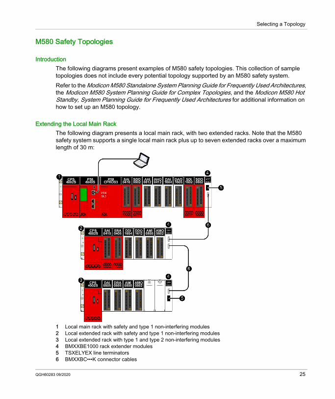
Extending the Local Main RackThe following diagram presents a local main rack, with two extended racks. Note that the M580 safety system supports a single local main rack plus up to seven extended racks over a maximum length of 30 m:
1 Local main rack with safety and type 1 non-interfering modules2 Local extended rack with safety and type 1 non-interfering modules3 Local extended rack with type 1 and type 2 non-interfering modules4 BMXXBE1000 rack extender modules5 TSXELYEX line terminators6 BMXXBC•••K connector cables
QGH60283 09/2020 25
Selecting a Topology
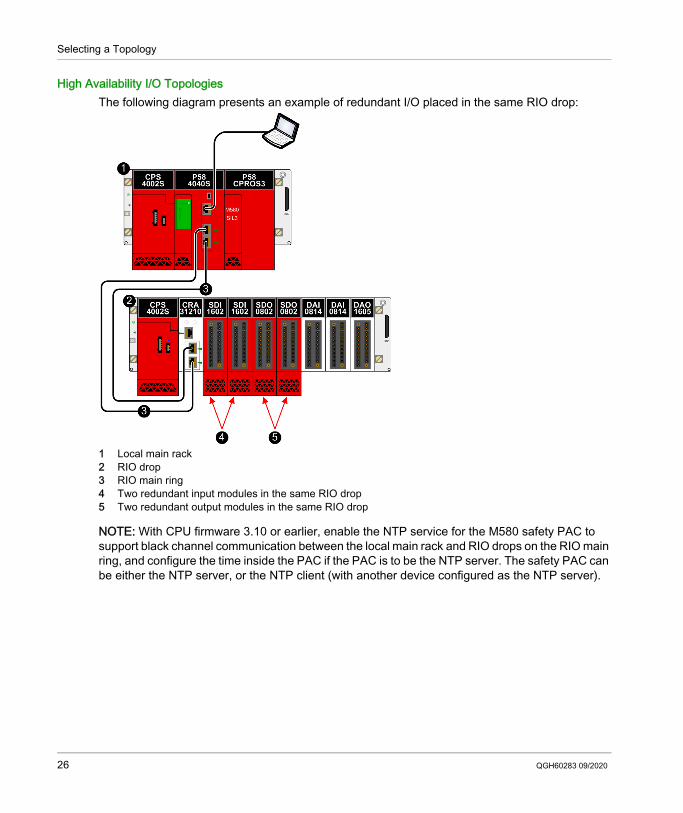
High Availability I/O TopologiesThe following diagram presents an example of redundant I/O placed in the same RIO drop:
1 Local main rack2 RIO drop3 RIO main ring4 Two redundant input modules in the same RIO drop5 Two redundant output modules in the same RIO drop
NOTE: With CPU firmware 3.10 or earlier, enable the NTP service for the M580 safety PAC to support black channel communication between the local main rack and RIO drops on the RIO main ring, and configure the time inside the PAC if the PAC is to be the NTP server. The safety PAC can be either the NTP server, or the NTP client (with another device configured as the NTP server).
26 QGH60283 09/2020
Selecting a Topology
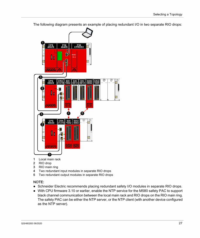
The following diagram presents an example of placing redundant I/O in two separate RIO drops:
1 Local main rack2 RIO drop3 RIO main ring4 Two redundant input modules in separate RIO drops5 Two redundant output modules in separate RIO drops
NOTE: Schneider Electric recommends placing redundant safety I/O modules in separate RIO drops. With CPU firmware 3.10 or earlier, enable the NTP service for the M580 safety PAC to support
black channel communication between the local main rack and RIO drops on the RIO main ring. The safety PAC can be either the NTP server, or the NTP client (with another device configured as the NTP server).
QGH60283 09/2020 27
Selecting a Topology
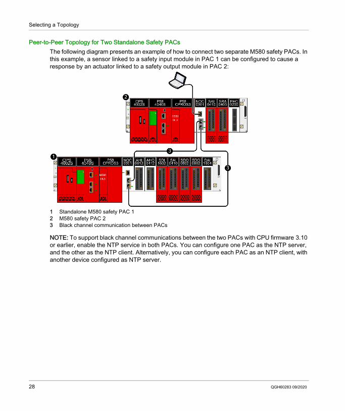
Peer-to-Peer Topology for Two Standalone Safety PACsThe following diagram presents an example of how to connect two separate M580 safety PACs. In this example, a sensor linked to a safety input module in PAC 1 can be configured to cause a response by an actuator linked to a safety output module in PAC 2:
1 Standalone M580 safety PAC 12 M580 safety PAC 23 Black channel communication between PACs
NOTE: To support black channel communications between the two PACs with CPU firmware 3.10 or earlier, enable the NTP service in both PACs. You can configure one PAC as the NTP server, and the other as the NTP client. Alternatively, you can configure each PAC as an NTP client, with another device configured as NTP server.
28 QGH60283 09/2020
Selecting a Topology
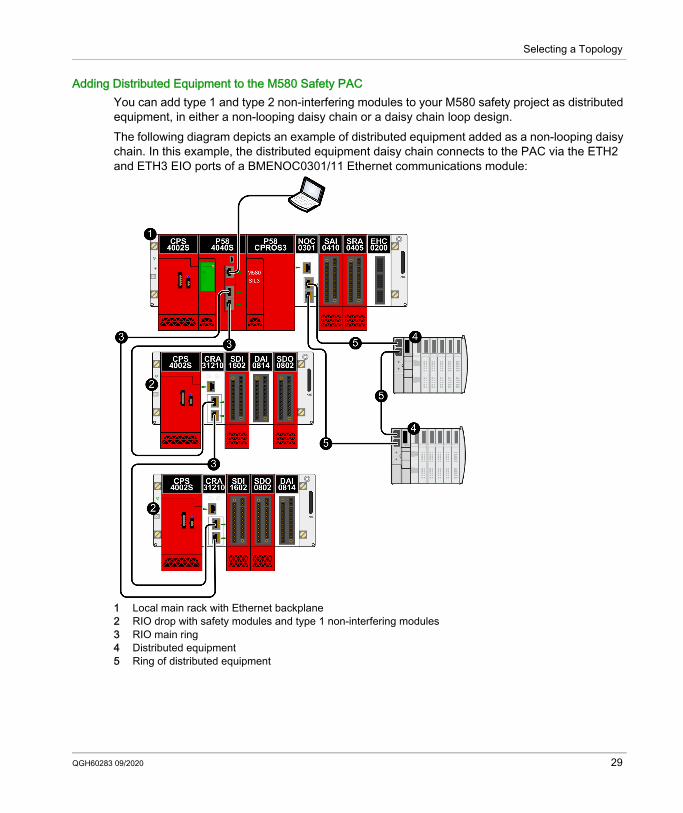
Adding Distributed Equipment to the M580 Safety PACYou can add type 1 and type 2 non-interfering modules to your M580 safety project as distributed equipment, in either a non-looping daisy chain or a daisy chain loop design.The following diagram depicts an example of distributed equipment added as a non-looping daisy chain. In this example, the distributed equipment daisy chain connects to the PAC via the ETH2 and ETH3 EIO ports of a BMENOC0301/11 Ethernet communications module:
1 Local main rack with Ethernet backplane2 RIO drop with safety modules and type 1 non-interfering modules3 RIO main ring4 Distributed equipment5 Ring of distributed equipment
QGH60283 09/2020 29

Selecting a Topology
Hot Standby TopologyThe following diagram presents a Hot Standby topology:
1 Primary local rack with primary CPU2 Standby local rack with standby CPU3 Hot Standby communication link4 Ethernet RIO main ring5 (e)X80 RIO drop
30 QGH60283 09/2020
Modicon M580M580 Safety CPU and CoprocessorQGH60283 09/2020
M580 Safety CPU and Coprocessor
Chapter 3M580 Safety CPU and Coprocessor
IntroductionThis chapter describes the BME•58•040S CPUs and the BMEP58CPROS3 Coprocessor (Copro).
What Is in This Chapter?This chapter contains the following sections:
Section Topic Page3.1 M580 Safety CPU & Coprocessor Physical Features 323.2 M580 Safety CPU & Coprocessor Performance Characteristics 48
QGH60283 09/2020 31
M580 Safety CPU and Coprocessor
M580 Safety CPU & Coprocessor Physical Features
Section 3.1M580 Safety CPU & Coprocessor Physical Features
IntroductionThis section describes the physical common features of the BME•58•040S CPUs and the BMEP58CPROS3 coprocessor (Copro).
What Is in This Section?This section contains the following topics:
Topic PagePhysical Description of the M580 Safety CPU & Coprocessor 33LED Displays for the M580 Safety CPU and Copro 38Ethernet Ports 40USB Port 43SFP Socket 45SD Memory Card 46
32 QGH60283 09/2020
M580 Safety CPU and Coprocessor
Physical Description of the M580 Safety CPU & Coprocessor
Position on the Local RackEvery M580 standalone SIL3 safety system requires one BME•58•040S CPU and one BMEP58CPROS3 coprocessor (Copro). The CPU requires two module slots and is placed in slots 0 and 1 immediately to the right of the power supply in the main local rack. The Copro also requires two module slots and is placed in slots 2 and 3 immediately to the right of the CPU. Both the CPU nor the Copro cannot be placed into any other slot locations or on any other rack. If there are extended racks in the local rack configuration, assign address 00 to the rack with the CPU and Copro.NOTE: Both the safety CPU and the Copro can be installed only on a BMEXBP•••• Ethernet rack. For a description of available M580 racks refer to the topic Local and Remote Racks in the Modicon M580 Hardware Reference Manual.
CPU Front PanelBME•58•040S safety CPU supports both RIO and DIO scanning.CPU Physical features:
Legend:
Item Marking Description1 – LED display (see page 38) for CPU status and diagnostics.2 Mini-B USB connector (see page 43) to which you can attach a PC
running Control Expert or firmware update tool, or an HMI.
3 Service RJ45 Ethernet connector (see page 40) for the service port.
QGH60283 09/2020 33
M580 Safety CPU and Coprocessor
Coprocessor Front PanelThe BMEP58CPROS3 Coprocessor presents only an LED display on its front face.
CPU & Copro DimensionsThe BME•58•040S safety CPUs present the following physical dimensions:
4 Dual Port Dual RJ45 Ethernet connectors (see page 40) that support distributed equipment and RIO drops.
5 Dual Port SFP socket for copper or fiber-optic redundant link connection.6 — Redundant link status LED.7 — SD memory card (see page 46) slot.8 — A/B/Clear rotary selector switch, used to designate a Hot Standby
PAC as either PAC A or PAC B, or to clear the existing Control Expert application.
Item Marking Description
34 QGH60283 09/2020
M580 Safety CPU and Coprocessor
The BMEP58CPROS3 Copro presents the following physical dimensions. Unlike the CPU, the Copro does not present physical connectors or related labels
NOTE: Consider the height of the CPU and Copro when you are planning the installation of the local rack. Both the CPU and Copro extend below the lower edge of the rack by: 29.49 mm (1.161 in.) for an Ethernet rack 30.9 mm (1.217 in.) for an X Bus rack
QGH60283 09/2020 35
M580 Safety CPU and Coprocessor
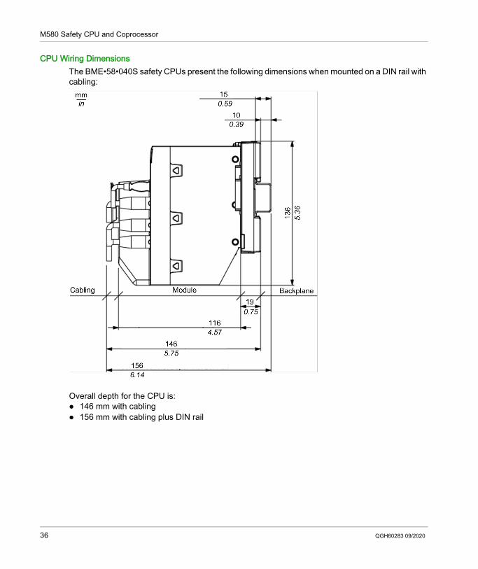
CPU Wiring DimensionsThe BME•58•040S safety CPUs present the following dimensions when mounted on a DIN rail with cabling:
Overall depth for the CPU is: 146 mm with cabling 156 mm with cabling plus DIN rail
36 QGH60283 09/2020
M580 Safety CPU and Coprocessor
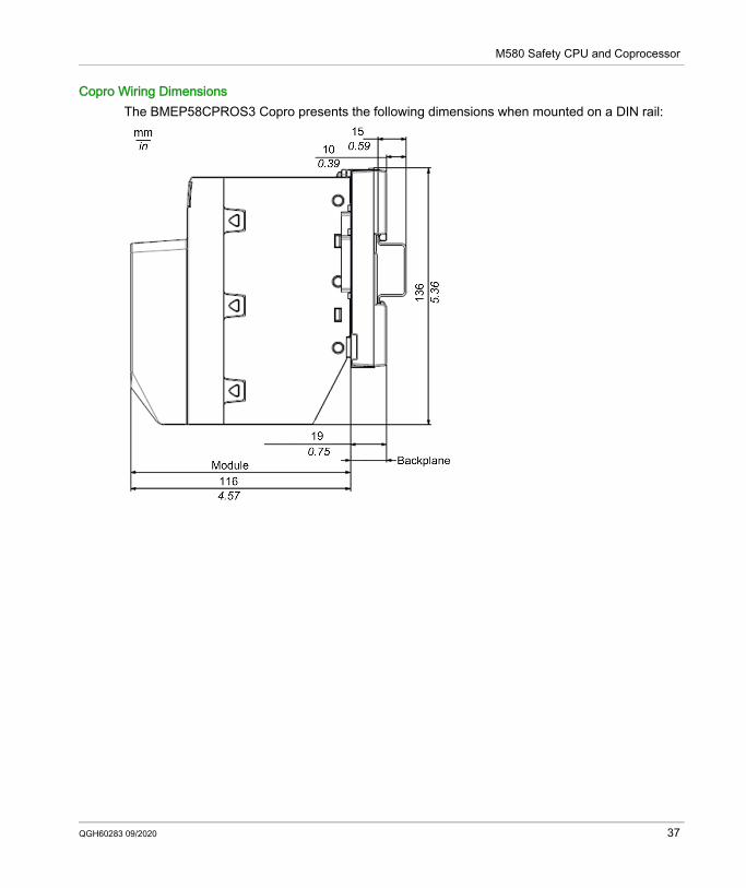
Copro Wiring DimensionsThe BMEP58CPROS3 Copro presents the following dimensions when mounted on a DIN rail:
QGH60283 09/2020 37
M580 Safety CPU and Coprocessor
LED Displays for the M580 Safety CPU and Copro
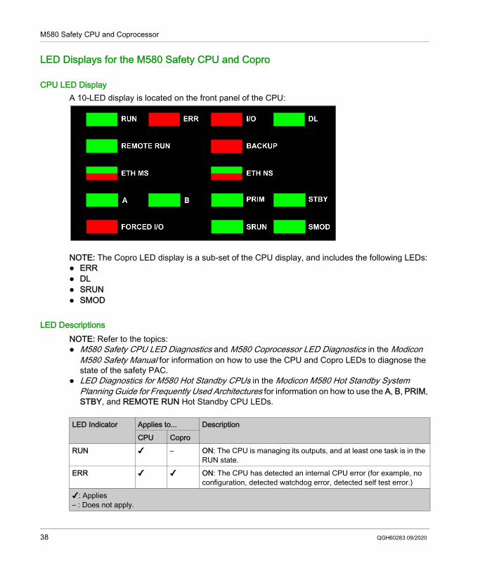
CPU LED DisplayA 10-LED display is located on the front panel of the CPU:
NOTE: The Copro LED display is a sub-set of the CPU display, and includes the following LEDs: ERR DL SRUN SMOD
LED DescriptionsNOTE: Refer to the topics: M580 Safety CPU LED Diagnostics and M580 Coprocessor LED Diagnostics in the Modicon
M580 Safety Manual for information on how to use the CPU and Copro LEDs to diagnose the state of the safety PAC.
LED Diagnostics for M580 Hot Standby CPUs in the Modicon M580 Hot Standby System Planning Guide for Frequently Used Architectures for information on how to use the A, B, PRIM, STBY, and REMOTE RUN Hot Standby CPU LEDs.
LED Indicator Applies to... DescriptionCPU Copro
RUN ✔ – ON: The CPU is managing its outputs, and at least one task is in the RUN state.
ERR ✔ ✔ ON: The CPU has detected an internal CPU error (for example, no configuration, detected watchdog error, detected self test error.)
✔: Applies– : Does not apply.
38 QGH60283 09/2020
M580 Safety CPU and Coprocessor
I/O ✔ – ON: The CPU has detected an error, external to the CPU, in one or more I/O modules.
DL (download) ✔ + ON: A firmware upgrade to the CPU, Copro, backplane or other in-rack module is in progress.
OFF: No firmware upgrade in progress.
BACKUP ✔ – ON: The memory card or CPU flash memory is missing or inoperable. The memory card is not usable (bad format, unrecognized type). The memory card or CPU flash memory content is inconsistent
with the current application. The memory card has been removed and reinserted. A PLC → Project Backup... → Backup Clear command has been
performed when no memory card is present. The BACKUP LED remains ON until the project is successfully backed up.
OFF: The memory card or CPU flash memory content is valid, and the application in the execution memory is identical.
ETH MS ✔ – MOD STATUS (green/red): Pattern indicates the Ethernet port configuration status.
NOTE: With the detection of a recoverable error, the ETH MS LED can be green or red and on or off.
ETH NS ✔ – NET STATUS (green/red): Pattern indicates the Ethernet connection status.
FORCED I/O ✔ – ON: At least one input or output on a digital I/O module is forced.SRUN ✔ ✔ ON: The PAC is managing its safety outputs, and the SAFE task is in
the RUN state.SMOD ✔ ✔ ON: The PAC is operating in safety mode (see page 110).
FLASHING: The PAC is operating in maintenance mode (see page 111).
LED Indicator Applies to... DescriptionCPU Copro
✔: Applies– : Does not apply.
QGH60283 09/2020 39
M580 Safety CPU and Coprocessor
Ethernet Ports
IntroductionThere are three RJ45 Ethernet ports on the front of the CPU: one service port, and two device network ports. The ports share the characteristics described below.
Common CharacteristicsAll three ports have the same RJ45 connector and all use the same type of Ethernet cables.NOTE: The three Ethernet ports are connected to chassis ground, and the system requires an equipotential ground.
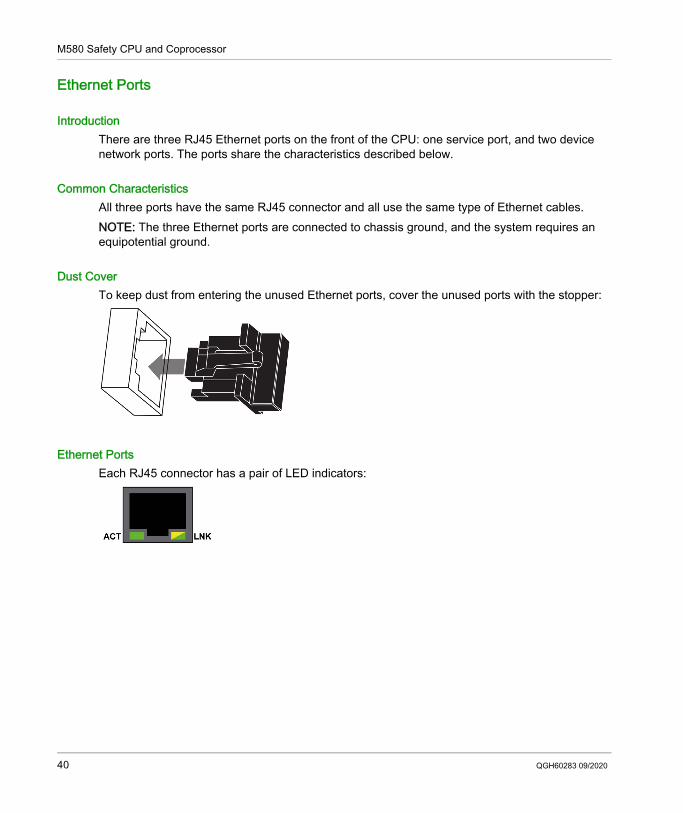
Dust CoverTo keep dust from entering the unused Ethernet ports, cover the unused ports with the stopper:
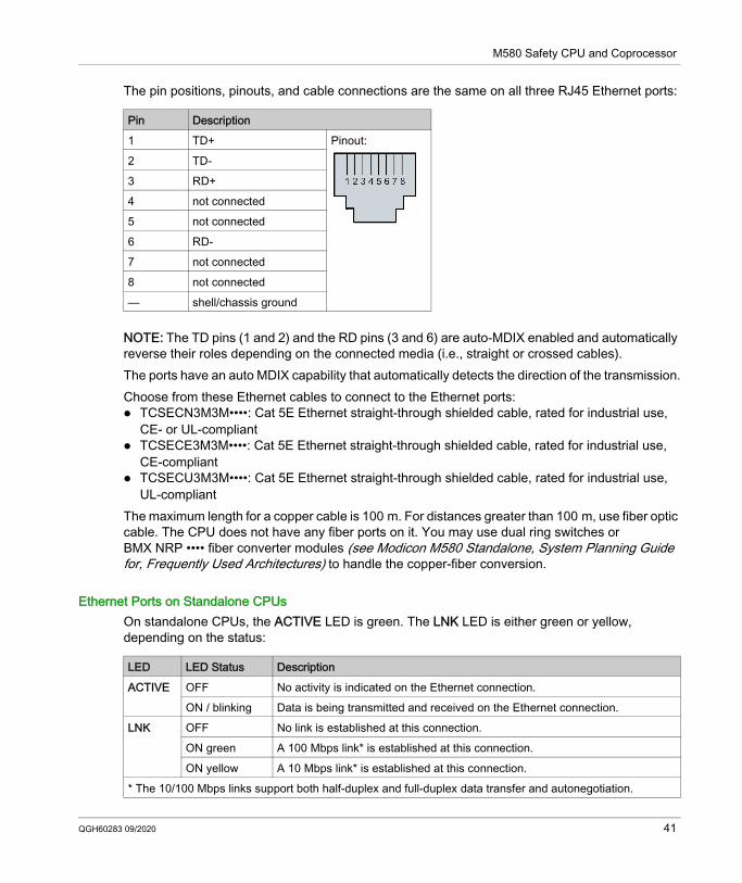
Ethernet PortsEach RJ45 connector has a pair of LED indicators:
40 QGH60283 09/2020
M580 Safety CPU and Coprocessor
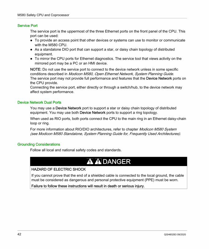
The pin positions, pinouts, and cable connections are the same on all three RJ45 Ethernet ports:
NOTE: The TD pins (1 and 2) and the RD pins (3 and 6) are auto-MDIX enabled and automatically reverse their roles depending on the connected media (i.e., straight or crossed cables).The ports have an auto MDIX capability that automatically detects the direction of the transmission.Choose from these Ethernet cables to connect to the Ethernet ports: TCSECN3M3M••••: Cat 5E Ethernet straight-through shielded cable, rated for industrial use,
CE- or UL-compliant TCSECE3M3M••••: Cat 5E Ethernet straight-through shielded cable, rated for industrial use,
CE-compliant TCSECU3M3M••••: Cat 5E Ethernet straight-through shielded cable, rated for industrial use,
UL-compliantThe maximum length for a copper cable is 100 m. For distances greater than 100 m, use fiber optic cable. The CPU does not have any fiber ports on it. You may use dual ring switches or BMX NRP •••• fiber converter modules (see Modicon M580 Standalone, System Planning Guide for, Frequently Used Architectures) to handle the copper-fiber conversion.
Ethernet Ports on Standalone CPUsOn standalone CPUs, the ACTIVE LED is green. The LNK LED is either green or yellow, depending on the status:
Pin Description1 TD+ Pinout:2 TD-3 RD+4 not connected5 not connected6 RD-7 not connected8 not connected— shell/chassis ground
LED LED Status DescriptionACTIVE OFF No activity is indicated on the Ethernet connection.
ON / blinking Data is being transmitted and received on the Ethernet connection.LNK OFF No link is established at this connection.
ON green A 100 Mbps link* is established at this connection.ON yellow A 10 Mbps link* is established at this connection.
* The 10/100 Mbps links support both half-duplex and full-duplex data transfer and autonegotiation.
QGH60283 09/2020 41
M580 Safety CPU and Coprocessor
Service PortThe service port is the uppermost of the three Ethernet ports on the front panel of the CPU. This port can be used: To provide an access point that other devices or systems can use to monitor or communicate
with the M580 CPU. As a standalone DIO port that can support a star, or daisy chain topology of distributed
equipment. To mirror the CPU ports for Ethernet diagnostics. The service tool that views activity on the
mirrored port may be a PC or an HMI device.NOTE: Do not use the service port to connect to the device network unless in some specific conditions described in Modicon M580, Open Ethernet Network, System Planning Guide.The service port may not provide full performance and features that the Device Network ports on the CPU provide.Connecting the service port, either directly or through a switch/hub, to the device network may affect system performance.
Device Network Dual PortsYou may use a Device Network port to support a star or daisy chain topology of distributed equipment. You may use both Device Network ports to support a ring topology.When used as RIO ports, both ports connect the CPU to the main ring in an Ethernet daisy-chain loop or ring.For more information about RIO/DIO architectures, refer to chapter Modicon M580 System (see Modicon M580 Standalone, System Planning Guide for, Frequently Used Architectures).
Grounding ConsiderationsFollow all local and national safety codes and standards.
DANGERHAZARD OF ELECTRIC SHOCKIf you cannot prove that the end of a shielded cable is connected to the local ground, the cable must be considered as dangerous and personal protective equipment (PPE) must be worn.Failure to follow these instructions will result in death or serious injury.
42 QGH60283 09/2020
M580 Safety CPU and Coprocessor
USB Port
IntroductionThe USB port is a high-speed, mini-B USB connector, version 2.0 (480 Mbps) that can be used for a Control Expert program or human-machine interface (HMI) panel. The USB port can connect to another USB port, version 1.1 or later.NOTE: Install M580 USB drivers before connecting the USB cable between the CPU and the PC.
TransparencyIf your system requires transparency between the device connected to the USB port and the M580 device network, add a persistent static route in the device’s routing table.Example of a command to address a device network with IP address X.X.0.0 (for a Windows PC): route add X.X.0.0 mask 255.255.0.0 90.0.0.1 -p(In this case, X.X.0.0 is the network address used by the M580 device network, and 255.255.0.0 is the corresponding subnet mask.)
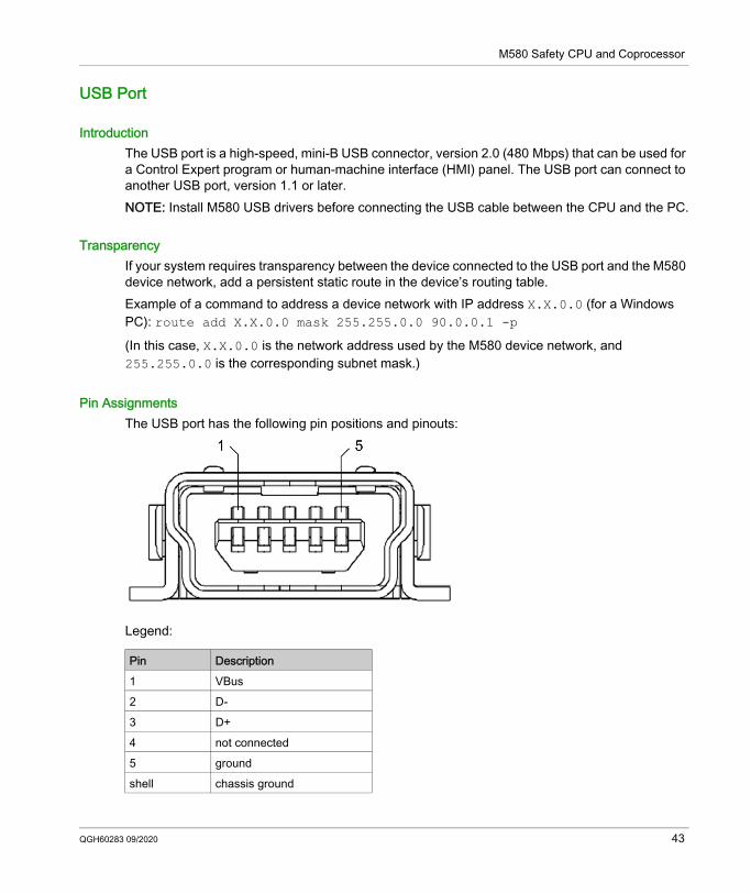
Pin AssignmentsThe USB port has the following pin positions and pinouts:
Legend:
Pin Description1 VBus2 D-3 D+4 not connected5 groundshell chassis ground
QGH60283 09/2020 43
M580 Safety CPU and Coprocessor
CablesUse a BMX XCA USB H018 (1.8 m/5.91 ft) or BMX XCA USB H045 (4.5 m/14.764 ft) cable to connect the panel to the CPU. (These cables have a type A connector on one side and the mini-B USB on the other side.)In a fixed assembly with an XBT-type console connected to the CPU, connect the USB cable to a protection bar (see Modicon X80, Racks and Power Supplies, Hardware Reference Manual). Use the exposed part of the shield or the metal lug on the BMX XCA cable to make the connection.
44 QGH60283 09/2020
M580 Safety CPU and Coprocessor
SFP Socket
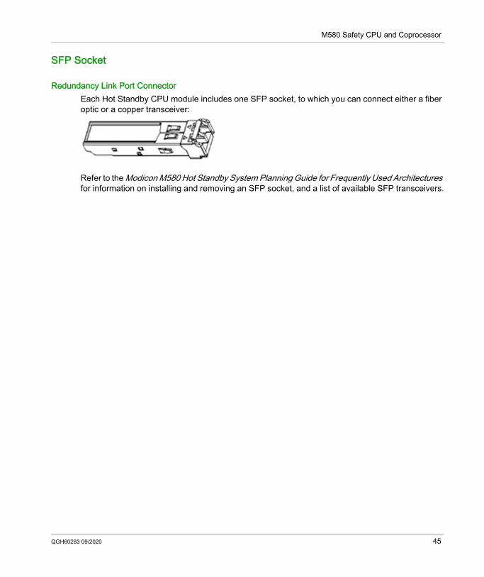
Redundancy Link Port ConnectorEach Hot Standby CPU module includes one SFP socket, to which you can connect either a fiber optic or a copper transceiver:
Refer to the Modicon M580 Hot Standby System Planning Guide for Frequently Used Architectures for information on installing and removing an SFP socket, and a list of available SFP transceivers.
QGH60283 09/2020 45
M580 Safety CPU and Coprocessor
SD Memory Card
BMXRMS004GPF SD Memory CardThe BMXRMS004GPF memory card is a 4 GB, Class 6 card rated for industrial use. The SD memory card slot resides behind the door on the front of the CPU.You can use a BMXRMS004GPF memory card for application and data storage. You can use a BMXRMS004GPF memory card for storage of: The M580 safety project application. Data for the non-safe tasks (MAST, FAST, AUX0, AUX1).NOTE: Data cannot be stored on the SD memory card for the SAFE task. The SD memory card is not included in the safety loop.You can insert and extract the card while power is ON and the PAC is in RUN mode. However, to avoid data losses, use system bit %S65 to make a system request to stop data access to the card before extracting it from the CPU.NOTE: Other memory cards, including those used in M340 CPUs, are not compatible with M580 CPUs. If you insert an incompatible SD memory card in the CPU: The CPU remains in NOCONF state (see Modicon M580, Hardware, Reference Manual). The CPU BACKUP LED turns ON. The memory card access LED remains blinking.The BMXRMS004GPF memory card is formatted specifically for the M580 CPUs. If you use this card with another CPU or tool, the card may not be recognized.
Memory Card CharacteristicsThe BMXRMS004GPF memory card presents the following characteristics:
NOTE: Due to formatting, wear-out, and other internal mechanisms, the actual available capacity of the memory card is slightly lower than its global size.
Characteristic Valueglobal memory size 4 GBapplication backup size 200 MBdata storage size 3.8 GBwrite/erase cycles (typical) 100,000operating temperature range –40...+85 °C (–40...+185 °F)file retention time 10 yearsmemory zone for FTP access data storage directory only
46 QGH60283 09/2020
M580 Safety CPU and Coprocessor
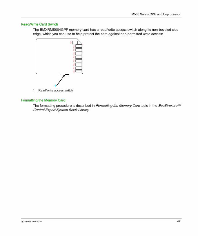
Read/Write Card SwitchThe BMXRMS004GPF memory card has a read/write access switch along its non-beveled side edge, which you can use to help protect the card against non-permitted write access:
1 Read/write access switch
Formatting the Memory CardThe formatting procedure is described in Formatting the Memory Card topic in the EcoStruxure™ Control Expert System Block Library.
QGH60283 09/2020 47
M580 Safety CPU and Coprocessor
M580 Safety CPU & Coprocessor Performance Characteristics
Section 3.2M580 Safety CPU & Coprocessor Performance Characteristics
M580 CPU & Copro Performance Characteristics
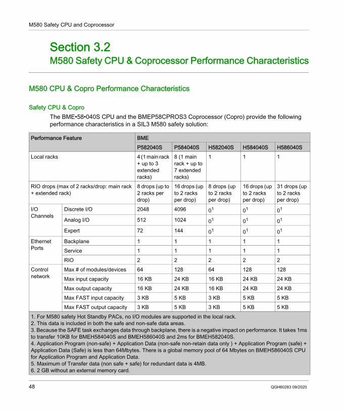
Safety CPU & CoproThe BME•58•040S CPU and the BMEP58CPROS3 Coprocessor (Copro) provide the following performance characteristics in a SIL3 M580 safety solution:
Performance Feature BMEP582040S P584040S H582040S H584040S H586040S
Local racks 4 (1 main rack + up to 3 extended racks)
8 (1 main rack + up to 7 extended racks)
1 1 1
RIO drops (max of 2 racks/drop: main rack + extended rack)
8 drops (up to 2 racks per drop)
16 drops (up to 2 racks per drop)
8 drops (up to 2 racks per drop)
16 drops (up to 2 racks per drop)
31 drops (up to 2 racks per drop)
I/O Channels
Discrete I/O 2048 4096 01 01 01
Analog I/O 512 1024 01 01 01
Expert 72 144 01 01 01
Ethernet Ports
Backplane 1 1 1 1 1Service 1 1 1 1 1RIO 2 2 2 2 2
Control network
Max # of modules/devices 64 128 64 128 128Max input capacity 16 KB 24 KB 16 KB 24 KB 24 KBMax output capacity 16 KB 24 KB 16 KB 24 KB 24 KBMax FAST input capacity 3 KB 5 KB 3 KB 5 KB 5 KBMax FAST output capacity 3 KB 5 KB 3 KB 5 KB 5 KB
1. For M580 safety Hot Standby PACs, no I/O modules are supported in the local rack.2. This data is included in both the safe and non-safe data areas.3. Because the SAFE task exchanges data through backplane, there is a negative impact on performance. It takes 1ms to transfer 10KB for BMEH584040S and BMEH586040S and 2ms for BMEH582040S.4. Application Program (non-safe) + Application Data (non-safe non-retain data only ) + Application Program (safe) + Application Data (Safe) is less than 64Mbytes. There is a global memory pool of 64 Mbytes on BMEH586040S CPU for Application Program and Application Data.5. Maximum of Transfer data (non safe + safe) for redundant data is 4MB.6. 2 GB without an external memory card.
48 QGH60283 09/2020
M580 Safety CPU and Coprocessor
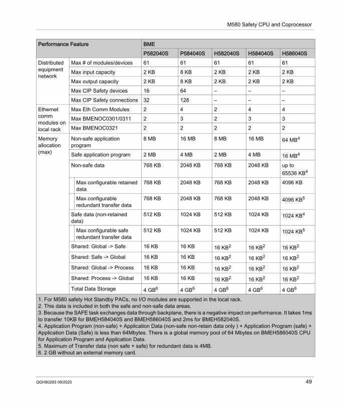
Distributed equipment network
Max # of modules/devices 61 61 61 61 61Max input capacity 2 KB 8 KB 2 KB 2 KB 2 KBMax output capacity 2 KB 8 KB 2 KB 2 KB 2 KBMax CIP Safety devices 16 64 – – –Max CIP Safety connections 32 128 – – –
Ethernet comm modules on local rack
Max Eth Comm Modules 2 4 2 4 4Max BMENOC0301/0311 2 3 2 3 3Max BMENOC0321 2 2 2 2 2
Memory allocation (max)
Non-safe application program
8 MB 16 MB 8 MB 16 MB 64 MB4
Safe application program 2 MB 4 MB 2 MB 4 MB 16 MB4
Non-safe data 768 KB 2048 KB 768 KB 2048 KB up to 65536 KB4
Max configurable retained data
768 KB 2048 KB 768 KB 2048 KB 4096 KB
Max configurable redundant transfer data
768 KB 2048 KB 768 KB 2048 KB 4096 KB5
Safe data (non-retained data)
512 KB 1024 KB 512 KB 1024 KB 1024 KB4
Max configurable safe redundant transfer data
512 KB 1024 KB 512 KB 1024 KB 1024 KB5
Shared: Global -> Safe 16 KB 16 KB 16 KB2 16 KB2 16 KB2
Shared: Safe -> Global 16 KB 16 KB 16 KB2 16 KB2 16 KB2
Shared: Global -> Process 16 KB 16 KB 16 KB2 16 KB2 16 KB2
Shared: Process -> Global 16 KB 16 KB 16 KB2 16 KB2 16 KB2
Total Data Storage 4 GB6 4 GB6 4 GB6 4 GB6 4 GB6
Performance Feature BMEP582040S P584040S H582040S H584040S H586040S
1. For M580 safety Hot Standby PACs, no I/O modules are supported in the local rack.2. This data is included in both the safe and non-safe data areas.3. Because the SAFE task exchanges data through backplane, there is a negative impact on performance. It takes 1ms to transfer 10KB for BMEH584040S and BMEH586040S and 2ms for BMEH582040S.4. Application Program (non-safe) + Application Data (non-safe non-retain data only ) + Application Program (safe) + Application Data (Safe) is less than 64Mbytes. There is a global memory pool of 64 Mbytes on BMEH586040S CPU for Application Program and Application Data.5. Maximum of Transfer data (non safe + safe) for redundant data is 4MB.6. 2 GB without an external memory card.
QGH60283 09/2020 49
M580 Safety CPU and Coprocessor
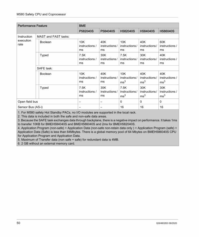
Instruction execution rate
MAST and FAST tasks:Boolean 10K
instructions / ms
40K instructions / ms
10K instructions / ms
40K instructions / ms
60K instructions / ms
Typed 7.5K instructions / ms
30K instructions / ms
7.5K instructions / ms
30K instructions / ms
40K instructions / ms
SAFE task:Boolean 10K
instructions / ms
40K instructions / ms
10K instructions / ms3
40K instructions / ms3
40K instructions / ms3
Typed 7.5K instructions / ms
30K instructions / ms
7.5K instructions / ms3
30K instructions / ms3
30K instructions / ms3
Open field bus – – 0 0 0Sensor Bus (AS-i) – – 16 16 16
Performance Feature BMEP582040S P584040S H582040S H584040S H586040S
1. For M580 safety Hot Standby PACs, no I/O modules are supported in the local rack.2. This data is included in both the safe and non-safe data areas.3. Because the SAFE task exchanges data through backplane, there is a negative impact on performance. It takes 1ms to transfer 10KB for BMEH584040S and BMEH586040S and 2ms for BMEH582040S.4. Application Program (non-safe) + Application Data (non-safe non-retain data only ) + Application Program (safe) + Application Data (Safe) is less than 64Mbytes. There is a global memory pool of 64 Mbytes on BMEH586040S CPU for Application Program and Application Data.5. Maximum of Transfer data (non safe + safe) for redundant data is 4MB.6. 2 GB without an external memory card.
50 QGH60283 09/2020
Modicon M580M580 Safety Power SuppliesQGH60283 09/2020
M580 Safety Power Supplies
Chapter 4M580 Safety Power Supplies
IntroductionThis chapter describes the M580 safety power supplies.
What Is in This Chapter?This chapter contains the following topics:
Topic PagePhysical Description of the M580 Safety Power Supplies 52M580 Safety Power Supply Performance Characteristics 57M580 Safety Power Supply Alarm Relay 62
QGH60283 09/2020 51
M580 Safety Power Supplies
Physical Description of the M580 Safety Power Supplies
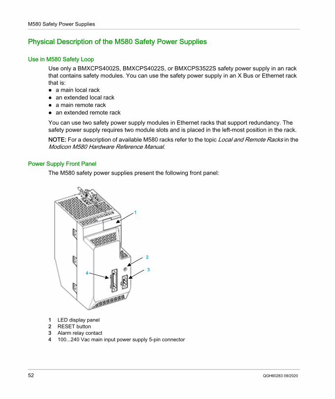
Use in M580 Safety LoopUse only a BMXCPS4002S, BMXCPS4022S, or BMXCPS3522S safety power supply in an rack that contains safety modules. You can use the safety power supply in an X Bus or Ethernet rack that is: a main local rack an extended local rack a main remote rack an extended remote rackYou can use two safety power supply modules in Ethernet racks that support redundancy. The safety power supply requires two module slots and is placed in the left-most position in the rack.NOTE: For a description of available M580 racks refer to the topic Local and Remote Racks in the Modicon M580 Hardware Reference Manual.
Power Supply Front PanelThe M580 safety power supplies present the following front panel:
1 LED display panel2 RESET button3 Alarm relay contact4 100...240 Vac main input power supply 5-pin connector
52 QGH60283 09/2020
M580 Safety Power Supplies
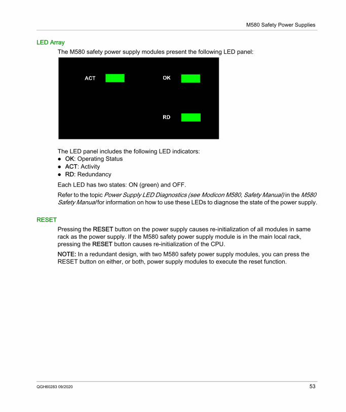
LED ArrayThe M580 safety power supply modules present the following LED panel:
The LED panel includes the following LED indicators: OK: Operating Status ACT: Activity RD: RedundancyEach LED has two states: ON (green) and OFF.Refer to the topic Power Supply LED Diagnostics (see Modicon M580, Safety Manual) in the M580 Safety Manual for information on how to use these LEDs to diagnose the state of the power supply.
RESETPressing the RESET button on the power supply causes re-initialization of all modules in same rack as the power supply. If the M580 safety power supply module is in the main local rack, pressing the RESET button causes re-initialization of the CPU.NOTE: In a redundant design, with two M580 safety power supply modules, you can press the RESET button on either, or both, power supply modules to execute the reset function.
QGH60283 09/2020 53
M580 Safety Power Supplies
Input Power Supply ConnectionsFor each M580 safety power supply, the following pin characteristics apply: 5 points Removable plug type: on the module: header with threaded flange plug terminal block with screw flange
Pitch: 5.08 mm Minimum wire capability: 0.5 mm2...2.0 mm2
The input power and pin assignments for each M580 safety power supply are as follows:
NOTE: A plug terminal block is provided with the module in the shipping materials.
Description BMXCPS4002S BMXCPS4022S BMXCPS3522SMain Input Power 100...240 Vac 24...48 Vdc 125 VdcPin 1 NC DC Line NCPin 2 NC DC Line NCPin 3 PE DC Neutral PEPin 4 AC Neutral DC Neutral DC NeutralPin 5 AC Line Earth DC Line
54 QGH60283 09/2020
M580 Safety Power Supplies
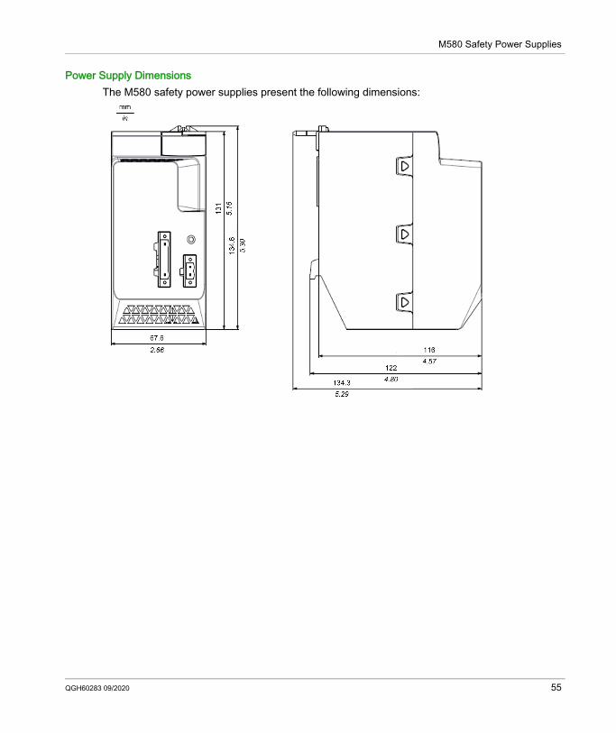
Power Supply DimensionsThe M580 safety power supplies present the following dimensions:
QGH60283 09/2020 55
M580 Safety Power Supplies
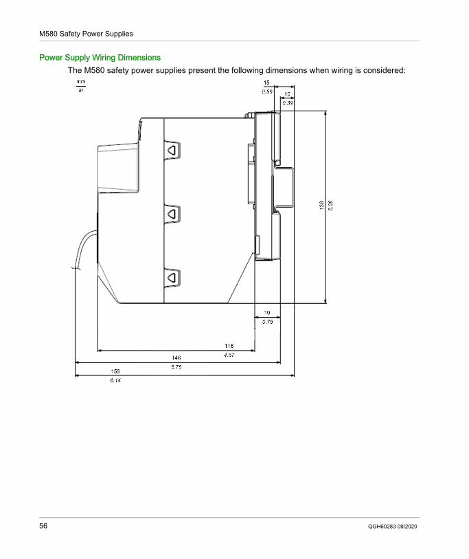
Power Supply Wiring DimensionsThe M580 safety power supplies present the following dimensions when wiring is considered:
56 QGH60283 09/2020
M580 Safety Power Supplies
M580 Safety Power Supply Performance Characteristics
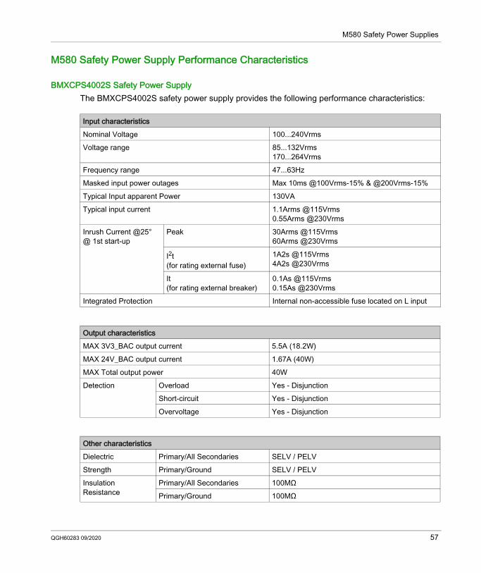
BMXCPS4002S Safety Power SupplyThe BMXCPS4002S safety power supply provides the following performance characteristics:
Input characteristicsNominal Voltage 100...240VrmsVoltage range 85...132Vrms
170...264VrmsFrequency range 47...63HzMasked input power outages Max 10ms @100Vrms-15% & @200Vrms-15%Typical Input apparent Power 130VATypical input current 1.1Arms @115Vrms
0.55Arms @230VrmsInrush Current @25°@ 1st start-up
Peak 30Arms @115Vrms60Arms @230Vrms
I2t (for rating external fuse)
1A2s @115Vrms4A2s @230Vrms
It (for rating external breaker)
0.1As @115Vrms0.15As @230Vrms
Integrated Protection Internal non-accessible fuse located on L input
Output characteristicsMAX 3V3_BAC output current 5.5A (18.2W)MAX 24V_BAC output current 1.67A (40W)MAX Total output power 40WDetection Overload Yes - Disjunction
Short-circuit Yes - DisjunctionOvervoltage Yes - Disjunction
Other characteristicsDielectric Primary/All Secondaries SELV / PELV Strength Primary/Ground SELV / PELV Insulation Resistance
Primary/All Secondaries 100MΩPrimary/Ground 100MΩ
QGH60283 09/2020 57
M580 Safety Power Supplies
BMXCPS4022S Safety Power Supply
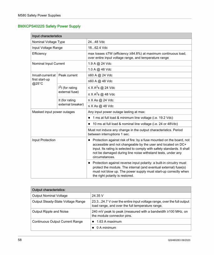
Input characteristicsNominal Voltage Type 24...48 VdcInput Voltage Range 18...62.4 VdcEfficiency max losses ≤7W (efficiency ≥84.8%) at maximum continuous load,
over entire input voltage range, and temperature rangeNominal Input Current 1.9 A @ 24 Vdc
1.0 A @ 48 VdcInrush current at first start-up @25°C
Peak current ≤60 A @ 24 Vdc ≤60 A @ 48 Vdc
I2t (for rating external fuse)
≤ X A2s @ 24 Vdc
≤ X A2s @ 48 Vdc It (for rating external breaker)
≤ X As @ 24 Vdc ≤ X As @ 48 Vdc
Masked input power outages Any input power outage lasting at max: 1 ms at full load & minimum line voltage (i.e. 19.2 Vdc)
10 ms at full load & nominal line voltage (i.e. 24 or 48Vdc)
Must not induce any change in the output characteristics. Period between interruptions 1 sec.
Input Protection Protection against risk of fire: by a fuse mounted on the board, not accessible and not changeable by the user and located on DC+ input. Its rating is selected to comply with safety standards. It shall not be damaged during line noise withstand tests, under any circumstances.
Protection against reverse input polarity: a built-in circuitry must protect the module. The internal (and eventual external) fuse(s) must not blow up. The power supply must start-up correctly when the right polarity is restored.
Output characteristics:Output Nominal Voltage 24.35 VOutput Steady-State Voltage Range 23.3...24.7 V over the entire input voltage range, over the full output
load range, and over the full temperature range.Output Ripple and Noise 240 mV peak to peak (measured with a bandwidth ≥100 MHz, on
the module connector pins.Continuous Output Current Range 1.63 A maximum
0 A minimum
58 QGH60283 09/2020
M580 Safety Power Supplies
BMXCPS3522S Safety Power Supply
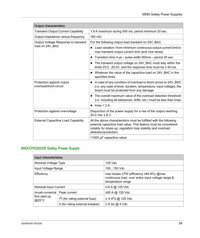
Transient Output Current Capability 1.9 A maximum during 500 ms, period minimum 20 sec.Output impedance versus frequency 180 mΩOutput Voltage Response to transient load on 24V_BAC
For the following output load transient on 24V_BAC: Load variation I from minimum continuous output current limit to
max transient output current limit (and vice versa). Transition time 4 μs – pulse width 500ms – period 20 sec.
The transient output voltage on 24V_BAC must stay within the limits 23.0...25.0V, and the response time must be ≤ 50 ms.
Whatever the value of the capacitive load on 24V_BAC in the specified limits.
Protection against output overload/short-circuit
In case of any condition of overload or short-circuit on 24V_BAC (i.e. any case of level, duration, temperature, input voltage), the board must be protected from any damage.
The overall maximum value of the overload detection threshold (i.e. including all tolerances, drifts, etc.) must be less than Imax.
Imax = 2 A.
Protection against overvoltage Disjunction of the power supply for a rise of the output reaching 30.0 Vdc ±.8 V.
External Capacitive Load Capability All the above characteristics must be fulfilled with the following external capacitive load value. This feature must be considered notably for slope-up, regulation loop stability and overload detection/protection.11500 μF capacitive value.
Output characteristics:
Input characteristics:Nominal Voltage Type 125 VdcInput Voltage Range 100...150 VdcEfficiency max losses ≤7W (efficiency ≥84.8%) @max
continuous load, over entire input voltage range & temperature range
Nominal Input Current 0.6 A @ 125 VdcInrush current at first start-up @25°C
Peak current ≤60 A @ 125 Vdc
I2t (for rating external fuse) ≤ X A2s @ 125 Vdc It (for rating external breaker) ≤ X As @ 4 Vdc
QGH60283 09/2020 59
M580 Safety Power Supplies
Masked input power outages Any input power outage lasting at max : 1 ms at full load & minimum line voltage (i.e. 100 Vdc)
10 ms at full load & nominal line voltage (i.e. 125 Vdc)
Must not induce any change in the output characteristics. Period between interruptions 1 sec.
Input Protection Protection against risk of fire : by a fuse mounted on the board, not accessible and not changeable by the user and located on DC+ input. Its rating is selected to comply with safety standards. It shall not be damaged during line noise withstand tests, under any circumstances.
Protection against reverse input polarity: a built-in circuitry must protect the module. The internal (and eventual external) fuse(s) must not blow up. The power supply must start-up correctly when the right polarity is restored.
BMXCPS3522 /S High Power Output Nominal Voltage 24.35 VOutput Steady-State Voltage Range 23.3...24.7 V over the entire input voltage range, over the full output
load range and over the full temperature range.Output Ripple and Noise 240 mV peak to peak (measured with a bandwidth ≥100 MHz, on
the module connector pins.Continuous Output Current Range 1.63 A maximum
0 A minimum
Transient Output Current Capability 1.9 A maximum during 500ms, period minimum 20 sec.Output impedance versus frequency 180 mΩOutput Voltage Response to transient load on 24V_BAC
For the following output load transient on 24V_BAC: Load variation I from minimum continuous output current limit to
max transient output current limit (and vice versa). Transition time 4 μs – pulse width 500ms – period 20 sec.
The transient output voltage on 24V_BAC must stay within the limits 23.0...25.0V, and the response time must be ≤ 50 ms.
Whatever the value of the capacitive load on 24V_BAC in the specified limits.
Input characteristics:
60 QGH60283 09/2020
M580 Safety Power Supplies
Protection against output overload/short-circuit
In case of any condition of overload or short-circuit on 24V_BAC (i.e. any case of level, duration, temperature, input voltage), the board must be protected from any damage.
The overall maximum value of the overload detection threshold (i.e. including all tolerances, drifts, etc.) must be less than Imax.
Imax = 2 A.
Protection against overvoltage Disjunction of the power supply for a rise of the output reaching 30.0 Vdc ±.8 V.
External Capacitive Load Capability All the above characteristics must be fulfilled with the following external capacitive load value. This feature must be considered notably for slope-up, regulation loop stability and overload detection/protection.11500 μF capacitive value.
BMXCPS3522 /S High Power
QGH60283 09/2020 61
M580 Safety Power Supplies
M580 Safety Power Supply Alarm Relay
Performance CharacteristicsThe alarm relay terminal block on the M580 safety power supplies present the following performance characteristics:
CharacteristicsRated switching Voltage / Current 24 Vdc 2A (Restive load)
240 Vac 2A (cos φ =1) pointMinimum switching load 5 Vdc 1 mAMaximum switching voltage 62.4 Vdc
264 VacContact type Normally openContact time OFF → ON 10 ms or Less
ON → OFF 12 ms or Less
Built-in protection Against overload / short-circuits: none, a fast-blow fuse must be fitted.Against inductive overvoltage in AC: none, an RC circuit or a MOV (ZNO) suppressor (appropriate to the voltage) must be fitted in parallel to the terminals of each pre-actuator.Against inductive overvoltage in DC: none, a discharge diode must be fitted to the terminals of each pre-actuator.
Dielectric strength Contact vs ground: 2000 Vrms 50Hz 1min.(Altitude 0...2000 m)Insulation resistance 10 MΩ or more under 500 Vdc
62 QGH60283 09/2020
Modicon M580M580 Safety I/O ModulesQGH60283 09/2020
M580 Safety I/O Modules
Chapter 5M580 Safety I/O Modules
IntroductionThis chapter describes the M580 safety I/O modules.
What Is in This Chapter?This chapter contains the following sections:
Section Topic Page5.1 M580 Safety I/O Modules Physical Description 645.2 M580 Safety I/O Performance Characteristics 70
QGH60283 09/2020 63
M580 Safety I/O Modules
M580 Safety I/O Modules Physical Description
Section 5.1M580 Safety I/O Modules Physical Description
Physical Description of M580 I/O Modules
Positioning Safety I/O ModulesYou can install an M580 safety I/O module on: the local rack in any slot that is not reserved for the power supply or CPU. a remote rack in any slot that is not reserved for the power supply or remote adapter.NOTE: A safety I/O module can be installed on either a BMXXBP•••• X Bus rack or a BMEXBP•••• Ethernet rack. For a description of available M580 racks refer to the topic Local and Remote Racks in the Modicon M580 Hardware Reference Manual.
64 QGH60283 09/2020
M580 Safety I/O Modules
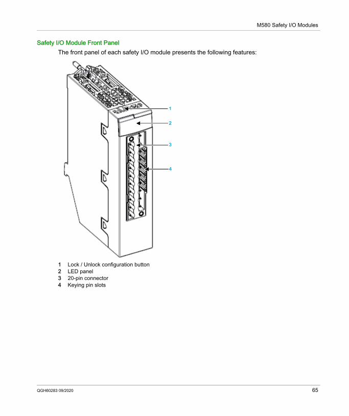
Safety I/O Module Front PanelThe front panel of each safety I/O module presents the following features:
1 Lock / Unlock configuration button2 LED panel3 20-pin connector4 Keying pin slots
QGH60283 09/2020 65
M580 Safety I/O Modules
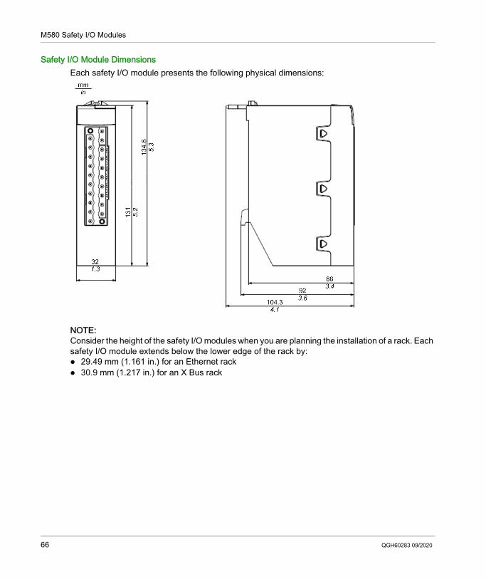
Safety I/O Module DimensionsEach safety I/O module presents the following physical dimensions:
NOTE: Consider the height of the safety I/O modules when you are planning the installation of a rack. Each safety I/O module extends below the lower edge of the rack by: 29.49 mm (1.161 in.) for an Ethernet rack 30.9 mm (1.217 in.) for an X Bus rack
66 QGH60283 09/2020
M580 Safety I/O Modules
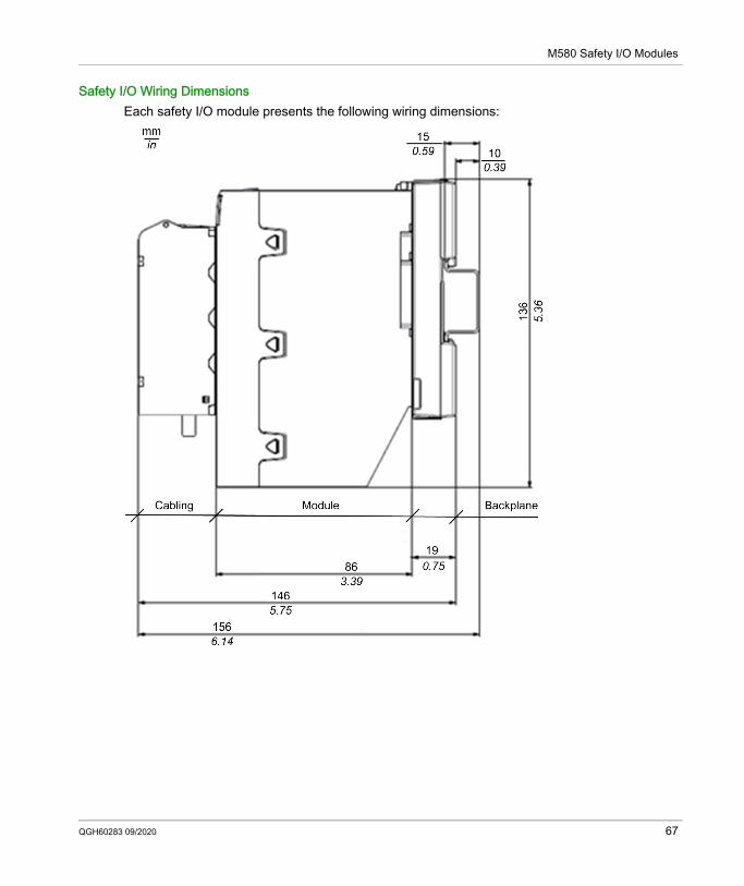
Safety I/O Wiring DimensionsEach safety I/O module presents the following wiring dimensions:
QGH60283 09/2020 67
M580 Safety I/O Modules
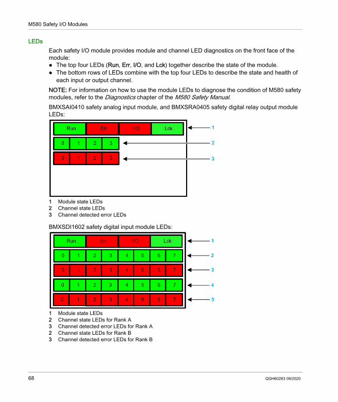
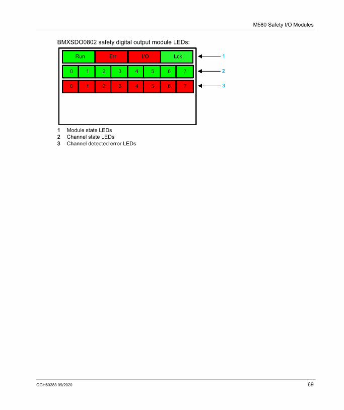
LEDsEach safety I/O module provides module and channel LED diagnostics on the front face of the module: The top four LEDs (Run, Err, I/O, and Lck) together describe the state of the module. The bottom rows of LEDs combine with the top four LEDs to describe the state and health of
each input or output channel.NOTE: For information on how to use the module LEDs to diagnose the condition of M580 safety modules, refer to the Diagnostics chapter of the M580 Safety Manual.BMXSAI0410 safety analog input module, and BMXSRA0405 safety digital relay output module LEDs:
1 Module state LEDs2 Channel state LEDs3 Channel detected error LEDs
BMXSDI1602 safety digital input module LEDs:
1 Module state LEDs2 Channel state LEDs for Rank A3 Channel detected error LEDs for Rank A2 Channel state LEDs for Rank B3 Channel detected error LEDs for Rank B
68 QGH60283 09/2020
M580 Safety I/O Modules
BMXSDO0802 safety digital output module LEDs:
1 Module state LEDs2 Channel state LEDs3 Channel detected error LEDs
QGH60283 09/2020 69
M580 Safety I/O Modules
M580 Safety I/O Performance Characteristics
Section 5.2M580 Safety I/O Performance Characteristics
IntroductionThis section describes the performance characteristics of the M580 safety I/O modules.
What Is in This Section?This section contains the following topics:
Topic PageBMXSAI0410 Safety Analog Input Module Performance Characteristics 71BMXSDI1602 Safety Digital Input Module Performance Characteristics 73BMXSDO0802 Safety Digital Output Module Performance Characteristics 75BMXSRA0405 Safety Digital Relay Output Module 77
70 QGH60283 09/2020
M580 Safety I/O Modules
BMXSAI0410 Safety Analog Input Module Performance Characteristics
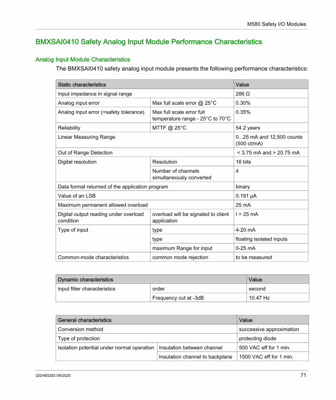
Analog Input Module CharacteristicsThe BMXSAI0410 safety analog input module presents the following performance characteristics:
Static characteristics ValueInput impedance in signal range 286 ΩAnalog input error Max full scale error @ 25°C 0.30%Analog input error (=safety tolerance) Max full scale error full
temperature range - 25°C to 70°C0.35%
Reliability MTTF @ 25°C 54.2 yearsLinear Measuring Range 0...25 mA and 12,500 counts
(500 ct/mA)Out of Range Detection < 3.75 mA and > 20.75 mADigital resolution Resolution 16 bits
Number of channels simultaneously converted
4
Data format returned of the application program binaryValue of an LSB 0.191 μAMaximum permanent allowed overload 25 mADigital output reading under overload condition
overload will be signaled to client application
I = 25 mA
Type of input type 4-20 mAtype floating isolated inputsmaximum Range for input 0-25 mA
Common-mode characteristics common mode rejection to be measured
Dynamic characteristics Valueinput filter characteristics order second
Frequency cut at -3dB 10.47 Hz
General characteristics ValueConversion method successive approximationType of protection protecting diodeIsolation potential under normal operation Insulation between channel 500 VAC eff for 1 min.
Insulation channel to backplane 1500 VAC eff for 1 min.
QGH60283 09/2020 71
M580 Safety I/O Modules
External power supply data - if required not requiredType & length of cable - installation rules recommended to provide interference immunity
shielded cable
Calibration or verification to maintain rated accuracy No calibrationTypical examples of external connections temperature sensor &
pressure sensor
Miscellaneous characteristics ValueMonotonicity with no missing code yesCrosstalk between at d.c. & a.c. 50Hz and a.c. 60Hz –Non-linearity +/- 0.006% (LSB)Repeatability at fixed temperature after specified stabilization time –3.3V consumption Typical 223 mA
Maximum 256 mA24V consumption Typical 92 mA
Maximum 115 mAPower dissipation Maximum 3.98 W
General characteristics Value
72 QGH60283 09/2020
M580 Safety I/O Modules
BMXSDI1602 Safety Digital Input Module Performance Characteristics
Digital Input Module CharacteristicsThe BMXSDI1602 safety input module presents the following performance characteristics:
Characteristic ValueNominal input Voltage 24 VDCType external sensor Power-supply
SELV/PELV, overvoltage II (Max 60 V)
Typical input current Current 3.2 mAInput limit values Voltage at state 1 ≥ 11 V
Voltage at state 0 ≤ 5 VCurrent at state 1 > 2 mA for U ≥ 11 VCurrent at state 0 < 1.5 mASensor supply(Ripple included)
From 19 to 30 V (Possible up to 33. Limited 1 hour per Day)
Input Impedance At Unom 7.5 KΩ Response time Typical/Maximum 100 μs/ 250 μsReliability MTTF @ Tamb = 25 °C 31.5 yearsReverse polarity ProtectedIEC61131-2 - Edition 3.0 (2007) Type 3Compatibility (2 wires, 3 wires prox. Sensors) IEC 947-5-2Dielectric strength Primaries/secondary 1500 VRMS (at 4000 m) 50/60 Hz for 1 minInsulation resistance > 10 MΩ (at 500 VDC)Input type Current sink
Input paralleling(1) Yes
Sensor voltageMonitoring threshold
OK > 18.6 VDC< 32 VDC
Fault < 18.6 VDC> 33 VDC
Sensor voltage monitoring response Time
On disappearance 4.4 ms < T < 30 ms On appearance 0.18 ms < T < 0.3 ms
Maximum external capacitance when using VS for short-circuit to 24V detection
Maximum 80 nF
(1) This characteristic enables several inputs to be wired on the same module, or on different modules if redundant inputs are required.
QGH60283 09/2020 73
M580 Safety I/O Modules
3.3V consumption Typical 200 mAMaximum 256 mA
24V consumption Typical 63 mAMaximum 100 mA
Max dissipated power 3.57 W
Characteristic Value
(1) This characteristic enables several inputs to be wired on the same module, or on different modules if redundant inputs are required.
74 QGH60283 09/2020
M580 Safety I/O Modules
BMXSDO0802 Safety Digital Output Module Performance Characteristics
Digital Output Module CharacteristicsThe BMXSDO0802 safety digital output module presents the following performance characteristics:
Characteristic ValueNominal values Voltage 24 VDC
Current 0.5 ALimit values Voltage 19...30 V(1)
Current/Channel 0.625 ACurrent/Module 5 A
Type external actuator Power-supply SELV/PELV (Max 60 V), Overvoltage category IITungsten filament lamp power
max 6 W
Leakage current At state 0 < 0.5 mAResidual voltage At state 1 < 1.2 VProtections Transient voltage yes
Overload disjunction current > 0.625 AShort circuit yesWrong polarity yesOver temperature yes
Minimum load. Resistance value (For pre-actuator) 48 ΩFull detection of CUT wire: Maximum cable load capacitance value (including pre-actuator capacitance) between output and pre-actuator
10 nF
Response time(2) 1.2 ms
Reliability: MTTF 45.8 years @ 25 °CSwitching frequency on inductive load 0.5 / LI2Hz with Fmax =2 HzOutput paralleling Yes (2 maximum)Compatibility with DC inputs Yes (Only sink type 3 or sink not IEC)Built-in protection Against overvoltage Yes - by internal TVS
Against reverse polarity Yes - by reverse-mounted diode. Provide a fuse to the pre-actuator 24 V.
Against short circuits and overloads
Yes - by current limiter and electronic circuit-breaker 1.5 In < Id < 2 In
(1) 33V permissible for 1 hour per 24h.(2) All outputs have fast demagnetization circuits for electromagnets. Electromagnet discharge time < L/R.
QGH60283 09/2020 75

M580 Safety I/O Modules
24V Preactuator voltage Monitoring threshold
OK > 19.0 V and < 31.8 VFault < 18.0 V and > 31.8 V
Preactuator voltage Monitoring response time
On disappearance 2 ms < T < 5.6 msOn appearance 10 ms < T < 15.6 ms
Consumption 3.3V Typical 240 mAMaximum 264 mA
Consumption 24V backplane
Typical 80 mAMaximum 90 mA
Consumption 24V pre-actuator (Without load current)
Typical 5 mAMaximum 15 mA
Dissipated power 4.4 W max Dielectric strength (output/ground or internal logic) 1500 V rms & 50/60 Hz for 1 minInsulation resistance > 10 MΩ at 500 VDC
Characteristic Value
(1) 33V permissible for 1 hour per 24h.(2) All outputs have fast demagnetization circuits for electromagnets. Electromagnet discharge time < L/R.
76 QGH60283 09/2020
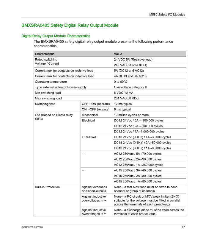
M580 Safety I/O Modules
BMXSRA0405 Safety Digital Relay Output Module
Digital Relay Output Module CharacteristicsThe BMXSRA0405 safety digital relay output module presents the following performance characteristics:
Characteristic ValueRated switchingVoltage / Current
24 VDC 5A (Resistive load)240 VAC 5A (cos Φ =1)
Current max for contacts on resistive load 5A (DC12 and AC12)Current max for contacts on inductive load 4A DC13 and 3A AC15Operating temperature 0 to 60°CType external actuator Power-supply Overvoltage category IIMin switching load 5 VDC 10 mAMax switching load 264 VAC 30 VDCSwitching time OFF→ ON (operate) 12 ms typical
ON →OFF (release) 6 ms typicalLife (Based on Elesta relay SIF3)
Mechanical 10 million cycles or moreElectrical DC12 24Vdc / 5A → 300.000 cycles
DC12 24Vdc / 2A →500.000 cyclesDC12 24Vdc / 1A→1.000.000 cycles
L/R=40ms DC13 24Vdc (0.1Hz) / 4A→30.000 cyclesDC13 24Vdc (0.1Hz) / 2A→50.000 cyclesDC13 24Vdc (0.1Hz) / 1A→80.000 cycles
– AC12 250Vac / 5A→70.000 cyclesAC12 250Vac / 2A→30.000 cyclesAC12 250Vac / 1A→250.000 cycles
– AC15 250Vac / 3A→40.000 cyclesAC15 250Vac / 2A→80.000 cyclesAC15 250Vac / 1A→80.000 cycles
Built-in Protection Against overloads and short-circuits
None - a fast blow fuse must be fitted to each channel or group of channels.
Against inductive overvoltages in ~
None - a RC circuit or MOV peak limiter (ZNO) suitable for the voltage must be fitted in parallel across the terminals of each preactuator.
Against inductive overvoltages in =
None - a discharge diode must be fitted across the terminals of each preactuator.
QGH60283 09/2020 77
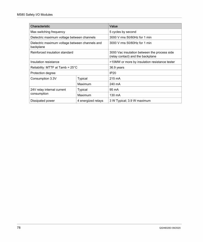
M580 Safety I/O Modules
Max switching frequency 5 cycles by secondDielectric maximum voltage between channels 3000 V rms 50/60Hz for 1 minDielectric maximum voltage between channels and backplane
3000 V rms 50/60Hz for 1 min
Reinforced insulation standard 3000 Vac insulation between the process side (relay contact) and the backplane
Insulation resistance >10MW or more by insulation resistance testerReliability: MTTF at Tamb = 25°C 36.9 yearsProtection degree IP20Consumption 3.3V Typical 215 mA
Maximum 240 mA24V relay internal current consumption
Typical 95 mAMaximum 130 mA
Dissipated power 4 energized relays 3 W Typical; 3.9 W maximum
Characteristic Value
78 QGH60283 09/2020
Modicon M580M580 Safety PAC InstallationQGH60283 09/2020
Installing the M580 Safety PAC
Chapter 6Installing the M580 Safety PAC
OverviewThis chapter explains how to install the M580 safety PAC.NOTE: For additional information on how to install M580 PACs, refer to the topic Installing a Local Rack in the Modicon M580 Hardware Reference Manual.
What Is in This Chapter?This chapter contains the following sections:
Section Topic Page6.1 Installing M580 Racks and Extender Modules 806.2 Installing M580 CPU, Copro, Power Supply, and I/O 89
QGH60283 09/2020 79
M580 Safety PAC Installation
Installing M580 Racks and Extender Modules
Section 6.1Installing M580 Racks and Extender Modules
IntroductionThis section describes how to install an M580 rack and extender modules for an M580 safety PAC.
What Is in This Section?This section contains the following topics:
Topic PagePlanning the Installation of the Local Rack 81Mounting the Racks 86Extending a Rack 88
80 QGH60283 09/2020
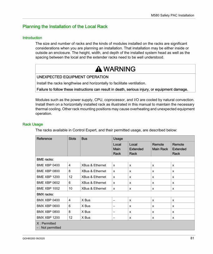
M580 Safety PAC Installation
Planning the Installation of the Local Rack
IntroductionThe size and number of racks and the kinds of modules installed on the racks are significant considerations when you are planning an installation. That installation may be either inside or outside an enclosure. The height, width, and depth of the installed system head as well as the spacing between the local and the extender racks need to be well understood.
Modules such as the power supply, CPU, coprocessor, and I/O are cooled by natural convection. Install them on a horizontally installed rack as illustrated in this manual to maintain the necessary thermal cooling. Other rack mounting positions may cause overheating and unexpected equipment operation.
Rack UsageThe racks available in Control Expert, and their permitted usage, are described below:
WARNINGUNEXPECTED EQUIPMENT OPERATIONInstall the racks lengthwise and horizontally to facilitate ventilation.Failure to follow these instructions can result in death, serious injury, or equipment damage.
Reference Slots Bus UsageLocal Main Rack
Local Extended Rack
Remote Main Rack
Remote Extended Rack
BME racks:BME XBP 0400 4 XBus & Ethernet x x x xBME XBP 0800 8 XBus & Ethernet x x x xBME XBP 1200 12 XBus & Ethernet x x x xBME XBP 0602 6 XBus & Ethernet x x x xBME XBP 1002 10 XBus & Ethernet x x x xBMX racks:BMX XBP 0400 4 X Bus – x x xBMX XBP 0600 6 X Bus – x x xBMX XBP 0800 8 X Bus – x x xBMX XBP 1200 12 X Bus – x x xX : Permitted– : Not permitted
QGH60283 09/2020 81
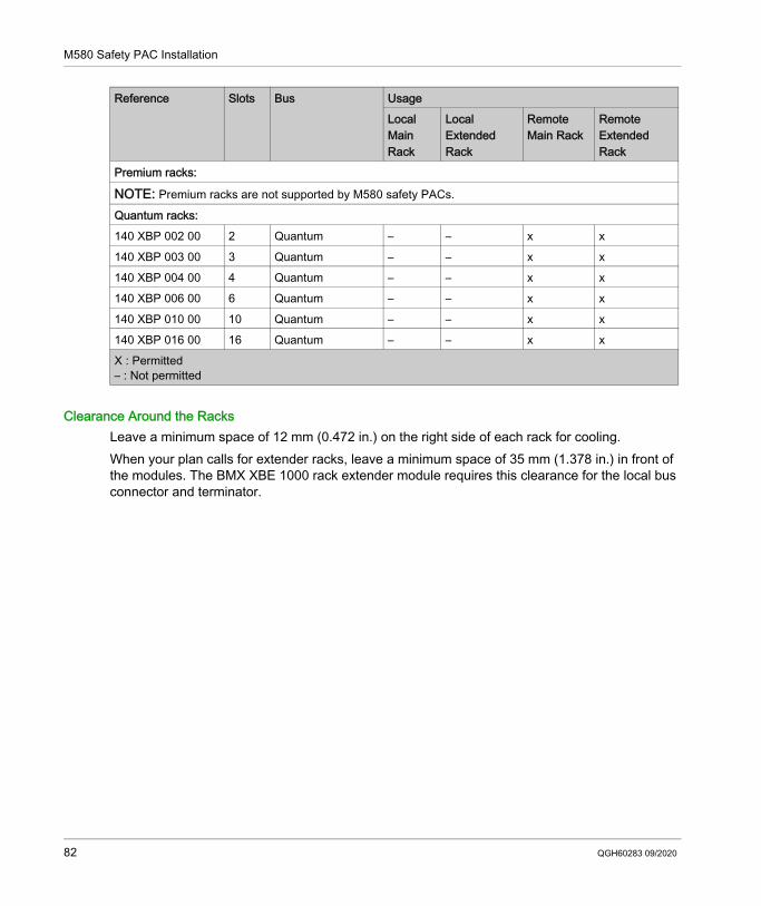
M580 Safety PAC Installation
Clearance Around the RacksLeave a minimum space of 12 mm (0.472 in.) on the right side of each rack for cooling.When your plan calls for extender racks, leave a minimum space of 35 mm (1.378 in.) in front of the modules. The BMX XBE 1000 rack extender module requires this clearance for the local bus connector and terminator.
Premium racks:
NOTE: Premium racks are not supported by M580 safety PACs.
Quantum racks:140 XBP 002 00 2 Quantum – – x x140 XBP 003 00 3 Quantum – – x x140 XBP 004 00 4 Quantum – – x x140 XBP 006 00 6 Quantum – – x x140 XBP 010 00 10 Quantum – – x x140 XBP 016 00 16 Quantum – – x x
Reference Slots Bus UsageLocal Main Rack
Local Extended Rack
Remote Main Rack
Remote Extended Rack
X : Permitted– : Not permitted
82 QGH60283 09/2020
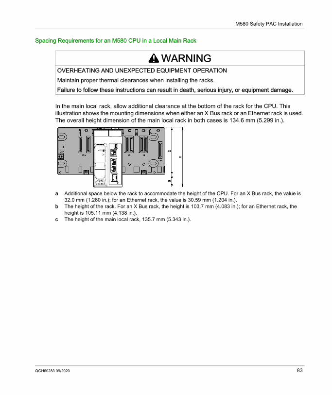
M580 Safety PAC Installation
Spacing Requirements for an M580 CPU in a Local Main Rack
In the main local rack, allow additional clearance at the bottom of the rack for the CPU. This illustration shows the mounting dimensions when either an X Bus rack or an Ethernet rack is used. The overall height dimension of the main local rack in both cases is 134.6 mm (5.299 in.).
a Additional space below the rack to accommodate the height of the CPU. For an X Bus rack, the value is 32.0 mm (1.260 in.); for an Ethernet rack, the value is 30.59 mm (1.204 in.).
b The height of the rack. For an X Bus rack, the height is 103.7 mm (4.083 in.); for an Ethernet rack, the height is 105.11 mm (4.138 in.).
c The height of the main local rack, 135.7 mm (5.343 in.).
WARNINGOVERHEATING AND UNEXPECTED EQUIPMENT OPERATIONMaintain proper thermal clearances when installing the racks.Failure to follow these instructions can result in death, serious injury, or equipment damage.
QGH60283 09/2020 83
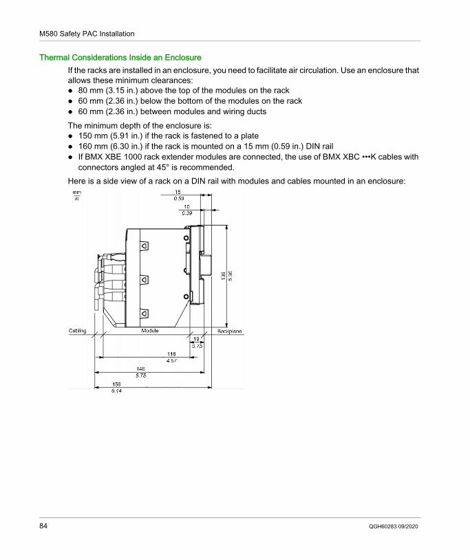
M580 Safety PAC Installation
Thermal Considerations Inside an EnclosureIf the racks are installed in an enclosure, you need to facilitate air circulation. Use an enclosure that allows these minimum clearances: 80 mm (3.15 in.) above the top of the modules on the rack 60 mm (2.36 in.) below the bottom of the modules on the rack 60 mm (2.36 in.) between modules and wiring ductsThe minimum depth of the enclosure is: 150 mm (5.91 in.) if the rack is fastened to a plate 160 mm (6.30 in.) if the rack is mounted on a 15 mm (0.59 in.) DIN rail If BMX XBE 1000 rack extender modules are connected, the use of BMX XBC •••K cables with
connectors angled at 45° is recommended.Here is a side view of a rack on a DIN rail with modules and cables mounted in an enclosure:
84 QGH60283 09/2020
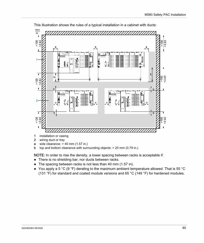
M580 Safety PAC Installation
This illustration shows the rules of a typical installation in a cabinet with ducts:
1 installation or casing2 wiring duct or traya side clearance: > 40 mm (1.57 in.)b top and bottom clearance with surrounding objects: > 20 mm (0.79 in.)
NOTE: In order to rise the density, a lower spacing between racks is acceptable if: There is no shielding bar, nor ducts between racks. The spacing between racks is not less than 40 mm (1.57 in). You apply a 5 °C (9 °F) derating to the maximum ambient temperature allowed. That is 55 °C
(131 °F) for standard and coated module versions and 65 °C (149 °F) for hardened modules.
QGH60283 09/2020 85
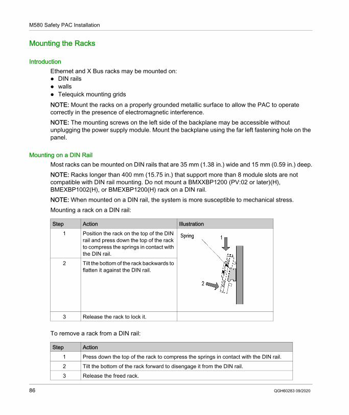
M580 Safety PAC Installation
Mounting the Racks
IntroductionEthernet and X Bus racks may be mounted on: DIN rails walls Telequick mounting gridsNOTE: Mount the racks on a properly grounded metallic surface to allow the PAC to operate correctly in the presence of electromagnetic interference.NOTE: The mounting screws on the left side of the backplane may be accessible without unplugging the power supply module. Mount the backplane using the far left fastening hole on the panel.
Mounting on a DIN RailMost racks can be mounted on DIN rails that are 35 mm (1.38 in.) wide and 15 mm (0.59 in.) deep.NOTE: Racks longer than 400 mm (15.75 in.) that support more than 8 module slots are not compatible with DIN rail mounting. Do not mount a BMXXBP1200 (PV:02 or later)(H), BMEXBP1002(H), or BMEXBP1200(H) rack on a DIN rail.NOTE: When mounted on a DIN rail, the system is more susceptible to mechanical stress.Mounting a rack on a DIN rail:
To remove a rack from a DIN rail:
Step Action Illustration1 Position the rack on the top of the DIN
rail and press down the top of the rack to compress the springs in contact with the DIN rail.
2 Tilt the bottom of the rack backwards to flatten it against the DIN rail.
3 Release the rack to lock it.
Step Action1 Press down the top of the rack to compress the springs in contact with the DIN rail.2 Tilt the bottom of the rack forward to disengage it from the DIN rail.3 Release the freed rack.
86 QGH60283 09/2020
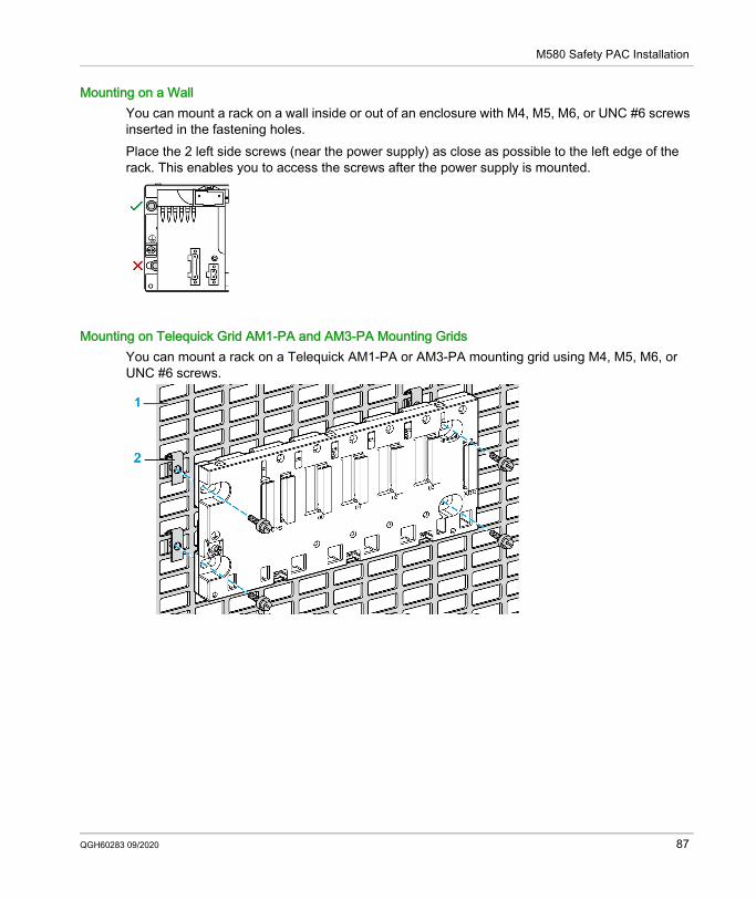
M580 Safety PAC Installation
Mounting on a WallYou can mount a rack on a wall inside or out of an enclosure with M4, M5, M6, or UNC #6 screws inserted in the fastening holes.Place the 2 left side screws (near the power supply) as close as possible to the left edge of the rack. This enables you to access the screws after the power supply is mounted.
Mounting on Telequick Grid AM1-PA and AM3-PA Mounting GridsYou can mount a rack on a Telequick AM1-PA or AM3-PA mounting grid using M4, M5, M6, or UNC #6 screws.
QGH60283 09/2020 87
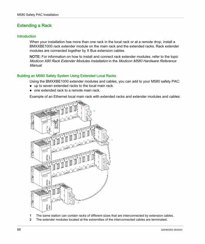
M580 Safety PAC Installation
Extending a Rack
IntroductionWhen your installation has more than one rack in the local rack or at a remote drop, install a BMXXBE1000 rack extender module on the main rack and the extended racks. Rack extender modules are connected together by X Bus extension cables.NOTE: For information on how to install and connect rack extender modules, refer to the topic Modicon X80 Rack Extender Modules Installation in the Modicon M580 Hardware Reference Manual.
Building an M580 Safety System Using Extended Local RacksUsing the BMXXBE1000 extender modules and cables, you can add to your M580 safety PAC: up to seven extended racks to the local main rack. one extended rack to a remote main rack. Example of an Ethernet local main rack with extended racks and extender modules and cables:
1 The same station can contain racks of different sizes that are interconnected by extension cables.2 The extender modules located at the extremities of the interconnected cables are terminated.
88 QGH60283 09/2020
M580 Safety PAC Installation
Installing M580 CPU, Copro, Power Supply, and I/O
Section 6.2Installing M580 CPU, Copro, Power Supply, and I/O
IntroductionThis section describes how to install an M580 safety CPU, coprocessor, power supply, and I/O modules.
What Is in This Section?This section contains the following topics:
Topic PageInstalling the CPU and Coprocessor 90Installing a Power Supply Module 93Installing M580 Safety I/O 97Installing an SD Memory Card in a CPU 99
QGH60283 09/2020 89

M580 Safety PAC Installation
Installing the CPU and Coprocessor
IntroductionYou can install the BME•58•040S CPU and BMEP58CPROS3 coprocessor only in either a BMEXBP••00 or BMEXBP••02 Ethernet rack.
Installation PrecautionsAn M580 CPU is powered by the rack bus. Confirm that the rack power supply is turned off before installing the CPU.
Remove the protective cover from the rack slot connectors before plugging the module in the rack.
NOTE: Check that the memory card slot door is closed after a memory card is inserted in the CPU. Refer to %SW97 to check the status of the SD card.
DANGERHAZARD OF ELECTRIC SHOCKRemove all power sources before installing the CPU.Failure to follow these instructions will result in death or serious injury.
WARNINGUNEXPECTED EQUIPMENT OPERATIONCheck that the CPU does not contain an unsupported SD memory card before powering up the CPU.Failure to follow these instructions can result in death, serious injury, or equipment damage.
90 QGH60283 09/2020
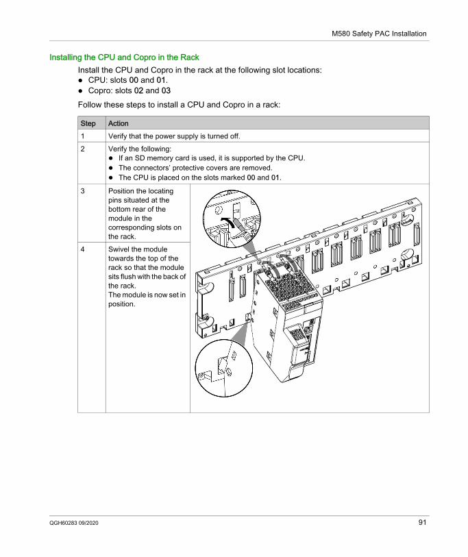
M580 Safety PAC Installation
Installing the CPU and Copro in the RackInstall the CPU and Copro in the rack at the following slot locations: CPU: slots 00 and 01. Copro: slots 02 and 03Follow these steps to install a CPU and Copro in a rack:
Step Action1 Verify that the power supply is turned off.2 Verify the following:
If an SD memory card is used, it is supported by the CPU. The connectors’ protective covers are removed. The CPU is placed on the slots marked 00 and 01.
3 Position the locating pins situated at the bottom rear of the module in the corresponding slots on the rack.
4 Swivel the module towards the top of the rack so that the module sits flush with the back of the rack.The module is now set in position.
QGH60283 09/2020 91
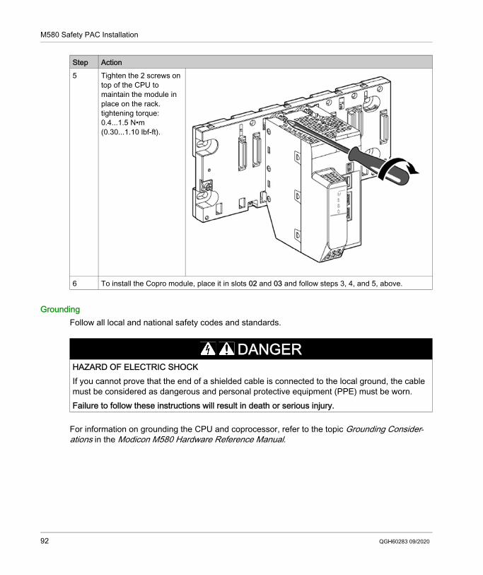
M580 Safety PAC Installation
GroundingFollow all local and national safety codes and standards.
For information on grounding the CPU and coprocessor, refer to the topic Grounding Consider-ations in the Modicon M580 Hardware Reference Manual.
5 Tighten the 2 screws on top of the CPU to maintain the module in place on the rack.tightening torque: 0.4...1.5 N•m (0.30...1.10 lbf-ft).
6 To install the Copro module, place it in slots 02 and 03 and follow steps 3, 4, and 5, above.
Step Action
DANGERHAZARD OF ELECTRIC SHOCKIf you cannot prove that the end of a shielded cable is connected to the local ground, the cable must be considered as dangerous and personal protective equipment (PPE) must be worn.Failure to follow these instructions will result in death or serious injury.
92 QGH60283 09/2020
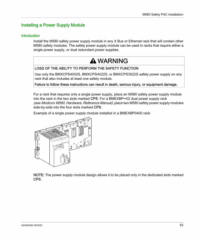
M580 Safety PAC Installation
Installing a Power Supply Module
IntroductionInstall the M580 safety power supply module in any X Bus or Ethernet rack that will contain other M580 safety modules. The safety power supply module can be used in racks that require either a single power supply, or dual redundant power supplies.
For a rack that requires only a single power supply, place an M580 safety power supply module into the rack in the two slots marked CPS. For a BMEXBP••02 dual power supply rack (see Modicon M580, Hardware, Reference Manual), place two M580 safety power supply modules side-by-side into the four slots marked CPS.Example of a single power supply module installed in a BMEXBP0400 rack:
NOTE: The power supply module design allows it to be placed only in the dedicated slots marked CPS.
WARNINGLOSS OF THE ABILITY TO PERFORM THE SAFETY FUNCTIONUse only the BMXCPS4002S, BMXCPS4022S, or BMXCPS3522S safety power supply on any rack that also includes at least one safety module.Failure to follow these instructions can result in death, serious injury, or equipment damage.
QGH60283 09/2020 93
M580 Safety PAC Installation
Installation PrecautionsThe M580 safety power supply module cannot be hot swapped. Confirm that the module is powered off when it is either inserted into the backplane, or extracted from the backplane.
Do not plug in, or unplug, the main input removable terminal block when voltage is being applied to the M580 safety power supply module. Confirm that power to the module from the upstream breaker is OFF before performing either of these tasks.
Do not plug in, or unplug, the alarm relay removable terminal block when the M580 safety power supply module is operating. Confirm that the module is de-energized before performing either of these tasks.
NOTICERISK OF UNINTENDED SYSTEM BEHAVIORConfirm that power is turned off when either removing an M580 safety power supply module from a rack, or inserting it into a rack. Failure to follow these instructions can result in equipment damage.
NOTICERISK OF UNINTENDED SYSTEM BEHAVIORConfirm that power is turned off – i.e. the upstream breaker must be OFF – before plugging in, or unplugging the main input removable terminal block of the M580 safety power supply module.Failure to follow these instructions can result in equipment damage.
NOTICERISK OF UNINTENDED SYSTEM BEHAVIORConfirm that the M580 safety power supply module is de-energized before plugging in, or unplugging the module’s alarm relay removable terminal block.Failure to follow these instructions can result in equipment damage.
94 QGH60283 09/2020
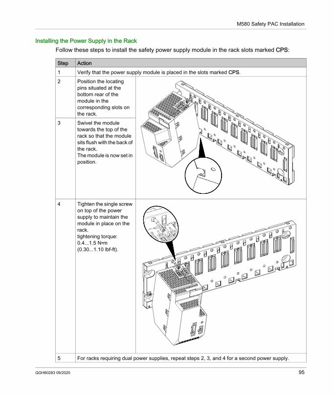
M580 Safety PAC Installation
Installing the Power Supply in the RackFollow these steps to install the safety power supply module in the rack slots marked CPS:
Step Action1 Verify that the power supply module is placed in the slots marked CPS.2 Position the locating
pins situated at the bottom rear of the module in the corresponding slots on the rack.
3 Swivel the module towards the top of the rack so that the module sits flush with the back of the rack.The module is now set in position.
4 Tighten the single screw on top of the power supply to maintain the module in place on the rack.tightening torque: 0.4...1.5 N•m (0.30...1.10 lbf-ft).
5 For racks requiring dual power supplies, repeat steps 2, 3, and 4 for a second power supply.
QGH60283 09/2020 95

M580 Safety PAC Installation
Grounding the Power Supply ModuleFollow all local and national safety codes and standards.
For information on grounding the power supply, refer to the topic Grounding the Rack and Power Supply Module.
DANGERHAZARD OF ELECTRIC SHOCKIf you cannot prove that the end of a shielded cable is connected to the local ground, the cable must be considered as dangerous and personal protective equipment (PPE) must be worn.Failure to follow these instructions will result in death or serious injury.
96 QGH60283 09/2020
M580 Safety PAC Installation
Installing M580 Safety I/O
IntroductionYou can install an M580 safety I/O module in any X Bus or Ethernet rack by placing it into any slot not reserved for the safety power supply or CPU (in the case of a local main rack). NOTE: Use only a BMXCPS4002S, BMXCPS4022S, or BMXCPS3522S safety power supply for any rack that includes safety I/O modules.You can hot swap M580 safety I/O.
General Cabling PrecautionsTo limit a DC load from interfering with an AC source, separate the power circuit cables (for example, cables leading to the power supply) from both input cables from sensors and output cables leading to actuators.Place cables connecting the CPU to I/O modules in a sheath that is enclosed by metal ducting. Keep the sheathing for I/O cables separate from power cabling that is placed in its own sheathing. Place sheathed power cables in separate ducting from the I/O cables. Power cables and I/O cables need to be separated by a minimum distance of 100 mm.
Grounding PrecautionsEach M580 safety I/O module is equipped with ground connection contacts.Schneider Electric recommends the use of a BMXXSP•••• bar to help protect the rack from electromagnetic disturbances.For the BMXSAI0410 safety analog input module, in particular, the use of a BMXXSP•••• bar is recommended. Connect the cable sheathing to the grounding bar by clamping it to the grounding bar on the module side.
Input Module Sensor Placement (In Relation to the Ground)When placing sensors in your system: Place sensors in close proximity to each other, separated by not more than a few meters. Reference all sensors to a single point, and connect that point to the PAC ground.
DANGERHAZARD OF ELECTRIC SHOCK, EXPLOSION, OR ARC FLASHWhile mounting or removing safety I/O modules: Verify that each terminal block remains connected to the BMXXSP•••• grounding bar. Disconnect voltage supplying the sensors or actuators.Failure to follow these instructions will result in death or serious injury.
QGH60283 09/2020 97
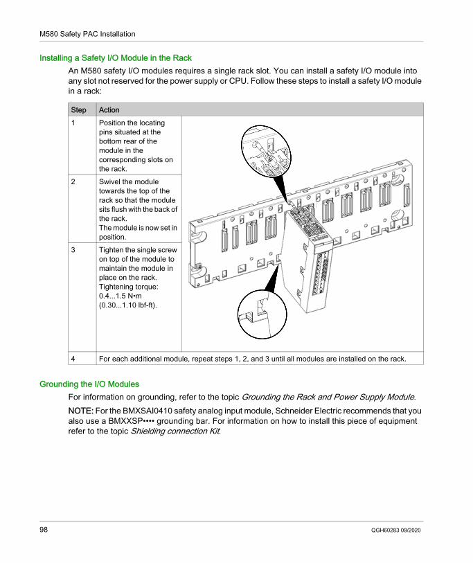
M580 Safety PAC Installation
Installing a Safety I/O Module in the RackAn M580 safety I/O modules requires a single rack slot. You can install a safety I/O module into any slot not reserved for the power supply or CPU. Follow these steps to install a safety I/O module in a rack:
Grounding the I/O ModulesFor information on grounding, refer to the topic Grounding the Rack and Power Supply Module.NOTE: For the BMXSAI0410 safety analog input module, Schneider Electric recommends that you also use a BMXXSP•••• grounding bar. For information on how to install this piece of equipment refer to the topic Shielding connection Kit.
Step Action1 Position the locating
pins situated at the bottom rear of the module in the corresponding slots on the rack.
2 Swivel the module towards the top of the rack so that the module sits flush with the back of the rack.The module is now set in position.
3 Tighten the single screw on top of the module to maintain the module in place on the rack.Tightening torque: 0.4...1.5 N•m (0.30...1.10 lbf-ft).
4 For each additional module, repeat steps 1, 2, and 3 until all modules are installed on the rack.
98 QGH60283 09/2020
M580 Safety PAC Installation
Installing an SD Memory Card in a CPU
IntroductionThe BME•58•040S CPU supports the use of the BMXRMS004GPF 4GB SD memory card.
Memory Card MaintenanceTo keep the memory card in normal working order: Avoid removing the memory card from its slot when the CPU accesses the card (memory card
access green LED ON or blinking). Avoid touching the memory card connectors. Keep the memory card away from electrostatic and electromagnetic sources as well as heat,
sunlight, water, and moisture. Avoid impact on the memory card. Before sending a memory card by post (mail), check the postal service security policy. In some
countries, the postal service exposes mail to high levels of radiation as a security measure. These high levels of radiation may erase the contents of the memory card and render it unusable.
If a card is extracted without generating a rising edge of the bit %S65 and without checking that the memory card access green LED is OFF, the data (files, application, and so on) may be lost or become unreliable.
Memory Card Insertion ProcedureProcedure for inserting a memory card into a BME•58•040S CPU:
Step Description1 Open the SD memory card protective door.2 Insert the card in its slot.3 Push the memory card until you hear a click.
Result: The card should now be clipped into its slot.Note: Insertion of the memory card does not force an application restore.
4 Close the memory card protective door.
QGH60283 09/2020 99
M580 Safety PAC Installation
Memory Card Removal ProcedureNOTE: Before removing a memory card, a rising edge on bit %S65 needs to be generated. If a card is extracted without generating a rising edge of the bit %S65 and without checking that the memory card access green LED is OFF, the data may be lost.Procedure for removing a memory card from a BME•58•040S CPU:
Step Description1 Generate a rising edge on bit %S65.
2 Check that the memory card access green LED is OFF.3 Open the SD memory card protective door.4 Push the memory card until you hear a click, then release the pressure on the card.
Result: The card should release from its slot.5 Remove the card from its slot.
Note: The memory card access green LED is ON when the memory card is removed from the CPU.
6 Close the memory card protective door.
100 QGH60283 09/2020
Modicon M580Firmware upgradeQGH60283 09/2020
Upgrading M580 Safety CPU Firmware
Chapter 7Upgrading M580 Safety CPU Firmware
What Is in This Chapter?This chapter contains the following topics:
Topic PageFirmware Update with Automation Device Maintenance 102Upgrading CPU Firmware with Unity Loader 103
QGH60283 09/2020 101
Firmware upgrade
Firmware Update with Automation Device Maintenance
OverviewThe EcoStruxure™ Automation Device Maintenance is a standalone tool that allows and simplifies the firmware update of devices in a plant (single or multiple).The tool supports the following features: Automatic device discovery Manual device identification Certificate management Firmware update for multiple devices simultaneouslyNOTE: For a description of the download procedure, refer to the EcoStruxure™ Automation Device Maintenance, User Guide.
102 QGH60283 09/2020
Firmware upgrade
Upgrading CPU Firmware with Unity Loader
Upgrading CPU FirmwareYou can update the CPU firmware by downloading a new firmware version with Unity Loader.Download the firmware through a connection to one of these: CPU mini-B USB connector CPU service port Ethernet networkNOTE: For a description of the download procedure, refer to Unity Loader, User Guide.
Enabling CPU Firmware UpdateTo enable the firmware update, you first need to unlock security for the CPU, as follows:
CPU Firmware FileSelect the firmware file (*.ldx) for the BME•58•040S safety CPU. The .ldx file contains firmware upgrades for the safety and process areas of the CPU and for its web pages.
CPU Firmware Update ProcedureTo upgrade the CPU firmware, follow these steps:
Step Action1 In the PLC Bus window, right-click on the Ethernet ports of the CPU.2 Select Open Submodule.3 Click on the Security tab.4 Click Unlock Security.
Step Action1 Install Unity Loader software.2 Connect the PC that is running Unity Loader to the CPU.3 Launch Unity Loader.4 Click Firmware tab.5 In the PC list box, select the .ldx file that contains the firmware file.6 When connected with Ethernet, check that the MAC address indicated in the PLC box
corresponds to the MAC address marked on the CPU.7 Check that transfer sign is green to allow transfer from PC to CPU.8 Click Transfer.
NOTE: During the firmware download process, the green DL LED on the CPU turns ON indicating the CPU is communicating only with the Unity Loader Software,
9 Click Close.
QGH60283 09/2020 103
Firmware upgrade
After the firmware upgrade process finishes: The CPU reboots with the new firmware. The application program stored in flash memory is preserved. The CPU performs a cold start and enters STOP mode, even if Automatic start in Run is
selected in the CPU Configuration tab.NOTE: If the firmware upgrade process is interrupted (for example, by a lost connection or a power outage), reset the CPU, which in this case will re-start using the old firmware.
Other M580 Safety Module FirmwareUpgrading the CPU firmware also upgrades the firmware of the coprocessor. Each time the coprocessor boots, it receives its operating system from the CPU.Firmware for the M580 safety power supply and I/O modules is not upgradable.
104 QGH60283 09/2020
Modicon M580OperationsQGH60283 09/2020
Operating an M580 Safety System
Chapter 8Operating an M580 Safety System
IntroductionThis chapter provides information on how to operate an M580 safety system.
What Is in This Chapter?This chapter contains the following sections:
Section Topic Page8.1 Process, Safety and Global Data Areas in Control Expert 1068.2 Operating Modes, Operating States, and Tasks 1098.3 Building an M580 Safety Project 1278.4 Locking M580 Safety I/O Module Configurations 1368.5 Initializing Data in Control Expert 1398.6 Working with Animation Tables in Control Expert 1408.7 Adding Code Sections 1448.8 Application Security Management 1558.9 Workstation Security Management 173
8.10 M580 Safety Project Settings 185
QGH60283 09/2020 105
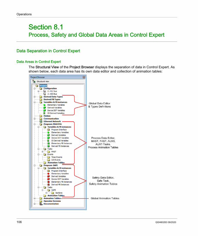
Operations
Process, Safety and Global Data Areas in Control Expert
Section 8.1Process, Safety and Global Data Areas in Control Expert
Data Separation in Control Expert
Data Areas in Control ExpertThe Structural View of the Project Browser displays the separation of data in Control Expert. As shown below, each data area has its own data editor and collection of animation tables:
106 QGH60283 09/2020
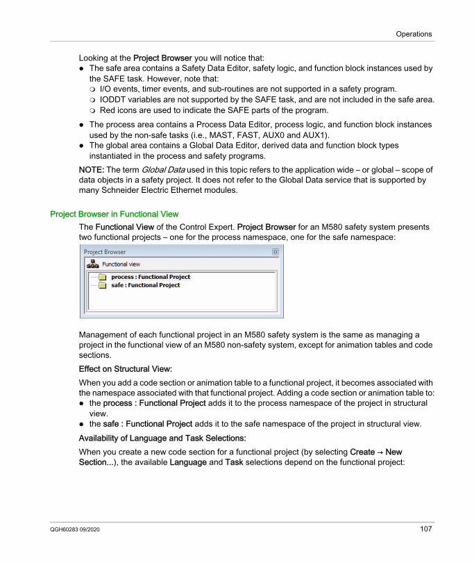
Operations
Looking at the Project Browser you will notice that: The safe area contains a Safety Data Editor, safety logic, and function block instances used by
the SAFE task. However, note that: I/O events, timer events, and sub-routines are not supported in a safety program. IODDT variables are not supported by the SAFE task, and are not included in the safe area. Red icons are used to indicate the SAFE parts of the program.
The process area contains a Process Data Editor, process logic, and function block instances used by the non-safe tasks (i.e., MAST, FAST, AUX0 and AUX1).
The global area contains a Global Data Editor, derived data and function block types instantiated in the process and safety programs.
NOTE: The term Global Data used in this topic refers to the application wide – or global – scope of data objects in a safety project. It does not refer to the Global Data service that is supported by many Schneider Electric Ethernet modules.
Project Browser in Functional ViewThe Functional View of the Control Expert. Project Browser for an M580 safety system presents two functional projects – one for the process namespace, one for the safe namespace:
Management of each functional project in an M580 safety system is the same as managing a project in the functional view of an M580 non-safety system, except for animation tables and code sections.Effect on Structural View:When you add a code section or animation table to a functional project, it becomes associated with the namespace associated with that functional project. Adding a code section or animation table to: the process : Functional Project adds it to the process namespace of the project in structural
view. the safe : Functional Project adds it to the safe namespace of the project in structural view.Availability of Language and Task Selections:When you create a new code section for a functional project (by selecting Create → New Section...), the available Language and Task selections depend on the functional project:
QGH60283 09/2020 107
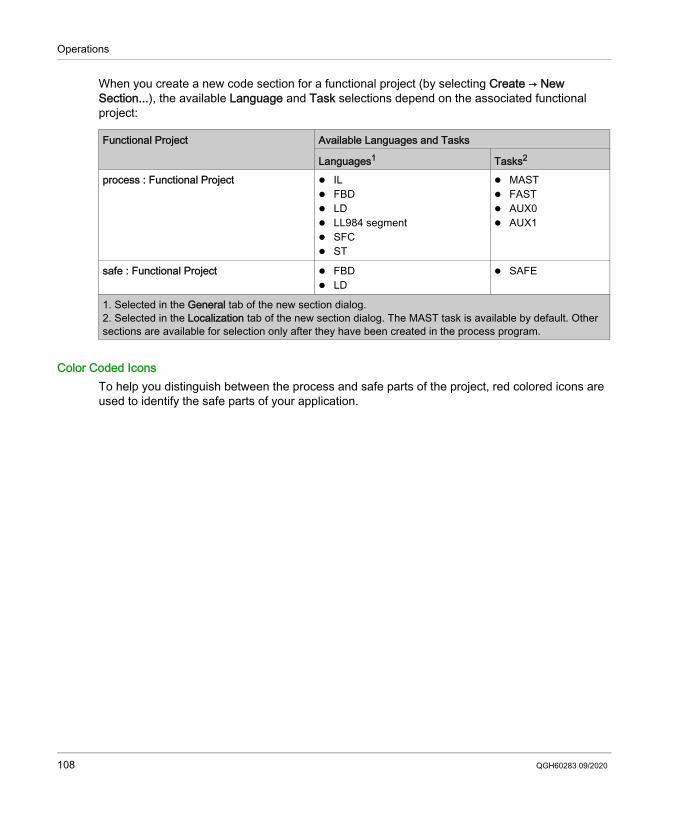
Operations
When you create a new code section for a functional project (by selecting Create → New Section...), the available Language and Task selections depend on the associated functional project:
Color Coded IconsTo help you distinguish between the process and safe parts of the project, red colored icons are used to identify the safe parts of your application.
Functional Project Available Languages and Tasks
Languages1 Tasks2
process : Functional Project IL FBD LD LL984 segment SFC ST
MAST FAST AUX0 AUX1
safe : Functional Project FBD LD
SAFE
1. Selected in the General tab of the new section dialog.2. Selected in the Localization tab of the new section dialog. The MAST task is available by default. Other sections are available for selection only after they have been created in the process program.
108 QGH60283 09/2020
Operations
Operating Modes, Operating States, and Tasks
Section 8.2Operating Modes, Operating States, and Tasks
IntroductionThis section describes the operating modes, operating states, and tasks supported by the M580 safety PAC.
What Is in This Section?This section contains the following topics:
Topic PageM580 Safety PAC Operating Modes 110M580 Safety PAC Operating States 115Start Up Sequences 120M580 Safety PAC Tasks 124
QGH60283 09/2020 109
Operations
M580 Safety PAC Operating Modes
Two Operating ModesThe M580 safety PAC presents two operating modes: Safety mode: the default operating mode used for safety operations. Maintenance mode: an optional operating mode that can be entered temporarily to debug and
modify the application program, or change the configuration.Control Expert XL Safety software is the exclusive tool you can use to manage operating mode transitions.NOTE: The operating mode setting of a Hot Standby safety PAC – either safety mode or maintenance mode – is not included in the transfer of an application from the primary PAC to the standby PAC. On a switchover, when a safety PAC switches from standby PAC to primary PAC, the operating mode is automatically set to safety mode.
Safety Mode and its LimitationsSafety mode is the default mode of safety PAC. When the safety PAC is powered ON with a valid application present, the PAC enters safety mode. Safety mode is used to control execution of the safety function. You can upload, download, run and stop the project in safety mode.When the M580 safety PAC is operating in safety mode, the following functions are not available: Downloading a changed configuration from Control Expert to the PAC. Editing and/or forcing safety variable values and safety I/O states. Debugging application logic, by means of breakpoints, watchpoints, and step-through code
execution. Using animation tables or UMAS requests (for example, from an HMI) to write to safety variables
and safety I/O. Changing the configuration settings of safety modules via CCOTF. (Note that the use of CCOTF
for non-interfering modules is supported.) Performing online modification of the safety application. Using link animation.NOTE: In safety mode, all safety variables and safety I/O states are read-only. You cannot directly edit the value of a safety variable.You can create a global variable, and use it to pass a value between a linked process (non-safe) variable and a linked safety variable using the interface tabs of the Process Data Editor and the Safety Data Editor. After the link is made, the transfer is executed as follows: At the beginning of each SAFE task, the non-safe variable values are copied to the safe
variables. At the end of the SAFE task, the safe output variable values are copied to the non-safe
variables.
110 QGH60283 09/2020
Operations
Maintenance Mode FunctionalityMaintenance mode is comparable to the normal mode of a non-safety M580 CPU. It is used only to debug and tune the application SAFE task. Maintenance mode is temporary because the safety PAC automatically enters safety mode if communication between Control Expert and the PAC is lost, or upon the execution of a disconnect command. In maintenance mode, persons with the appropriate permissions can both read and write to safety variables and safety I/O that are configured to accept edits.In maintenance mode, dual execution of SAFE task code is performed, but the results are not compared.When the M580 safety PAC is operating in maintenance mode, the following functions are available: Downloading a changed configuration from Control Expert to the PAC. Editing and/or forcing safety variable values and safety I/O states. Debugging application logic, by means of breakpoints, watchpoints, and step-through code
execution. Using animation tables or UMAS requests (for example, from an HMI) to write to safety variables
and safety I/O. Changing the configuration via CCOTF. Performing online modification of the safety application. Using link animation.In maintenance mode, the SIL level of the Safety PLC is not guaranteed.
WARNINGLOSS OF THE SAFETY INTEGRITY LEVELWhile the safety PAC is in maintenance mode, you need to take appropriate measures to ensure the safe state of the system.Failure to follow these instructions can result in death, serious injury, or equipment damage.
QGH60283 09/2020 111
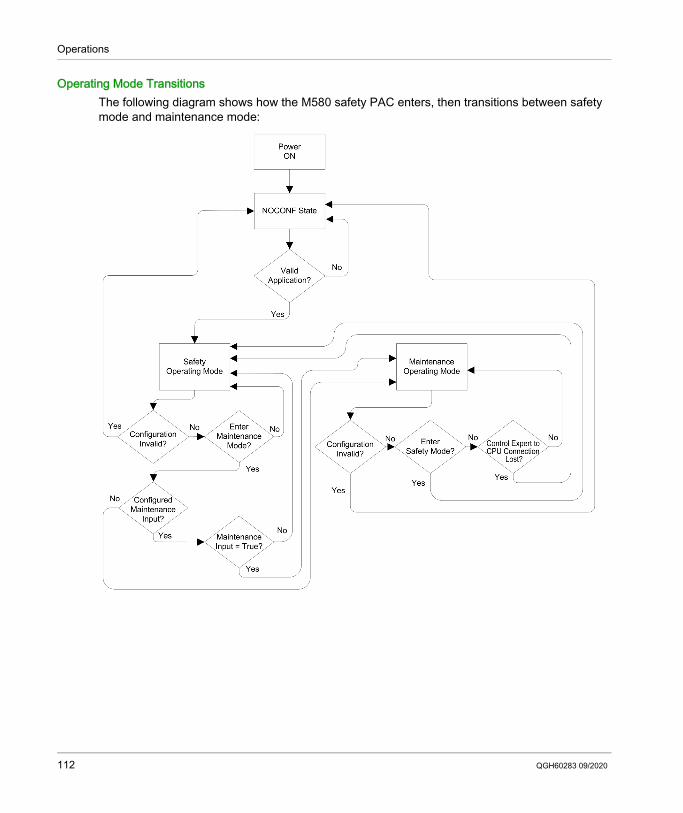
Operations
Operating Mode TransitionsThe following diagram shows how the M580 safety PAC enters, then transitions between safety mode and maintenance mode:
112 QGH60283 09/2020
Operations
When switching between safety mode and maintenance mode: It is OK to switch from maintenance mode to safety mode with forcing ON. In this case, the
forced variable value or I/O state remains forced after the transition until another transition from safety to maintenance mode occurs.
The transition from maintenance mode to safety mode can be accomplished in the following ways: Manually, by menu or toolbar command in Control Expert. Automatically, by the safety PAC, when communication between Control Expert and the PAC
is lost for about 50 seconds. The maintenance input function, when it is configured, operates as a check on the transition
from safety mode to maintenance mode. The maintenance input function is configured in Control Expert in the CPU Configuration tab by: Selecting the Maintenance Input setting, and Entering the topological address of an input bit (%I) for a non-interfering digital input module
on the local rack.When the maintenance input is configured, the transition from safety mode to maintenance mode takes into account the state of the designated input bit (%I). If the bit is set to 0 (false), the PAC is locked in safety mode. If the bit is set to 1 (true), a transition to maintenance mode can occur.
Switching Between Safety Mode and Maintenance Mode in Control ExpertSwitching the safety PAC from maintenance mode to safety mode is not possible if: The PAC is in debug mode. A breakpoint is activated in a SAFE task section. A watchpoint is set in a SAFE task section.When debug mode is not active, no SAFE task breakpoint is activated, and no SAFE task watchpoint is set, you can manually activate a transition between safety mode and maintenance mode, as follows: To switch from safety mode to maintenance mode, either: Select PLC → Maintenance, or
Click the toolbar button. To switch from maintenance mode to safety mode, either: Select PLC → Safety, or
Click the toolbar button.NOTE: Entering and exiting safety mode events are logged in the SYSLOG server in the CPU.
QGH60283 09/2020 113
Operations
Determining the Operating ModeYou can determine the current operating mode of an M580 safety PAC using either the SMOD LEDs of the CPU and coprocessor, or Control Expert.When the SMOD LEDs of the CPU and coprocessor are: Flashing ON, the PAC is in maintenance mode. Solid ON, the PAC is in safety mode.When Control Expert is connected to the PAC, it identifies the operating mode of the M580 safety PAC in several places: System words %SW12 (coprocessor) and %SW13 (CPU) (see page 202) together indicate the
operating mode of the PAC, as follows: if %SW12 is set to 16#A501 (hex) and %SW13 is set to 16#501A (hex), the PAC is in
maintenance mode. if either or both of these system words is set to 16#5AFE (hex), the PAC is in safety mode.
Both the Task and Information sub-tabs of the CPU Animation tab display the operating mode of the PAC.
The task bar, at the bottom of the Control Expert main window, indicates the operating mode as either MAINTENANCE or SAFETY.
114 QGH60283 09/2020
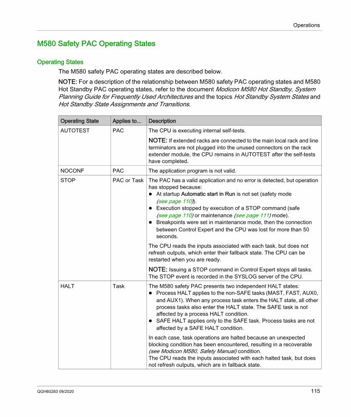
Operations
M580 Safety PAC Operating States
Operating StatesThe M580 safety PAC operating states are described below.NOTE: For a description of the relationship between M580 safety PAC operating states and M580 Hot Standby PAC operating states, refer to the document Modicon M580 Hot Standby, System Planning Guide for Frequently Used Architectures and the topics Hot Standby System States and Hot Standby State Assignments and Transitions.
Operating State Applies to... DescriptionAUTOTEST PAC The CPU is executing internal self-tests.
NOTE: If extended racks are connected to the main local rack and line terminators are not plugged into the unused connectors on the rack extender module, the CPU remains in AUTOTEST after the self-tests have completed.
NOCONF PAC The application program is not valid.STOP PAC or Task The PAC has a valid application and no error is detected, but operation
has stopped because: At startup Automatic start in Run is not set (safety mode
(see page 110)). Execution stopped by execution of a STOP command (safe
(see page 110) or maintenance (see page 111) mode). Breakpoints were set in maintenance mode, then the connection
between Control Expert and the CPU was lost for more than 50 seconds.
The CPU reads the inputs associated with each task, but does not refresh outputs, which enter their fallback state. The CPU can be restarted when you are ready.
NOTE: Issuing a STOP command in Control Expert stops all tasks. The STOP event is recorded in the SYSLOG server of the CPU.
HALT Task The M580 safety PAC presents two independent HALT states: Process HALT applies to the non-SAFE tasks (MAST, FAST, AUX0,
and AUX1). When any process task enters the HALT state, all other process tasks also enter the HALT state. The SAFE task is not affected by a process HALT condition.
SAFE HALT applies only to the SAFE task. Process tasks are not affected by a SAFE HALT condition.
In each case, task operations are halted because an unexpected blocking condition has been encountered, resulting in a recoverable (see Modicon M580, Safety Manual) condition.The CPU reads the inputs associated with each halted task, but does not refresh outputs, which are in fallback state.
QGH60283 09/2020 115
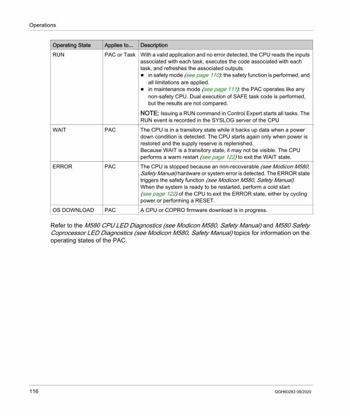
Operations
Refer to the M580 CPU LED Diagnostics (see Modicon M580, Safety Manual) and M580 Safety Coprocessor LED Diagnostics (see Modicon M580, Safety Manual) topics for information on the operating states of the PAC.
RUN PAC or Task With a valid application and no error detected, the CPU reads the inputs associated with each task, executes the code associated with each task, and refreshes the associated outputs. in safety mode (see page 110): the safety function is performed, and
all limitations are applied. in maintenance mode (see page 111): the PAC operates like any
non-safety CPU. Dual execution of SAFE task code is performed, but the results are not compared.
NOTE: Issuing a RUN command in Control Expert starts all tasks. The RUN event is recorded in the SYSLOG server of the CPU
WAIT PAC The CPU is in a transitory state while it backs up data when a power down condition is detected. The CPU starts again only when power is restored and the supply reserve is replenished.Because WAIT is a transitory state, it may not be visible. The CPU performs a warm restart (see page 122) to exit the WAIT state.
ERROR PAC The CPU is stopped because an non-recoverable (see Modicon M580, Safety Manual) hardware or system error is detected. The ERROR state triggers the safety function (see Modicon M580, Safety Manual).When the system is ready to be restarted, perform a cold start (see page 122) of the CPU to exit the ERROR state, either by cycling power or performing a RESET.
OS DOWNLOAD PAC A CPU or COPRO firmware download is in progress.
Operating State Applies to... Description
116 QGH60283 09/2020
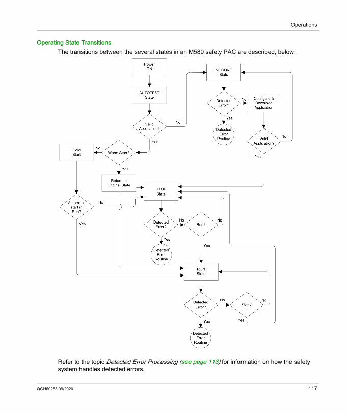
Operations
Operating State TransitionsThe transitions between the several states in an M580 safety PAC are described, below:
Refer to the topic Detected Error Processing (see page 118) for information on how the safety system handles detected errors.
QGH60283 09/2020 117
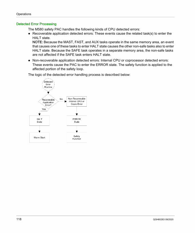
Operations
Detected Error ProcessingThe M580 safety PAC handles the following kinds of CPU detected errors: Recoverable application detected errors: These events cause the related task(s) to enter the
HALT state.NOTE: Because the MAST, FAST, and AUX tasks operate in the same memory area, an event that causes one of these tasks to enter HALT state causes the other non-safe tasks also to enter HALT state. Because the SAFE task operates in a separate memory area, the non-safe tasks are not affected if the SAFE task enters HALT state.
Non-recoverable application detected errors: Internal CPU or coprocessor detected errors: These events cause the PAC to enter the ERROR state. The safety function is applied to the affected portion of the safety loop.
The logic of the detected error handling process is described below:
118 QGH60283 09/2020
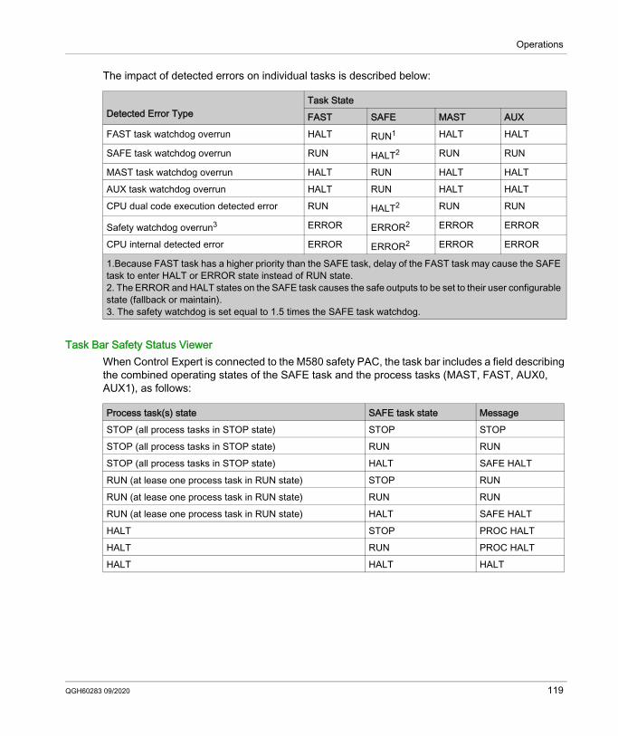
Operations
The impact of detected errors on individual tasks is described below:
Task Bar Safety Status ViewerWhen Control Expert is connected to the M580 safety PAC, the task bar includes a field describing the combined operating states of the SAFE task and the process tasks (MAST, FAST, AUX0, AUX1), as follows:
Detected Error Type
Task StateFAST SAFE MAST AUX
FAST task watchdog overrun HALT RUN1 HALT HALT
SAFE task watchdog overrun RUN HALT2 RUN RUN
MAST task watchdog overrun HALT RUN HALT HALTAUX task watchdog overrun HALT RUN HALT HALTCPU dual code execution detected error RUN HALT2 RUN RUN
Safety watchdog overrun3 ERROR ERROR2 ERROR ERROR
CPU internal detected error ERROR ERROR2 ERROR ERROR
1.Because FAST task has a higher priority than the SAFE task, delay of the FAST task may cause the SAFE task to enter HALT or ERROR state instead of RUN state.2. The ERROR and HALT states on the SAFE task causes the safe outputs to be set to their user configurable state (fallback or maintain).3. The safety watchdog is set equal to 1.5 times the SAFE task watchdog.
Process task(s) state SAFE task state MessageSTOP (all process tasks in STOP state) STOP STOPSTOP (all process tasks in STOP state) RUN RUNSTOP (all process tasks in STOP state) HALT SAFE HALTRUN (at lease one process task in RUN state) STOP RUNRUN (at lease one process task in RUN state) RUN RUNRUN (at lease one process task in RUN state) HALT SAFE HALTHALT STOP PROC HALTHALT RUN PROC HALTHALT HALT HALT
QGH60283 09/2020 119
Operations
Start Up Sequences
IntroductionThe M580 safety PAC can enter the start-up sequence in the following circumstances: At initial power-up. In response to a power interruption.Depending on the type of task, and the context of the power interruption, the M580 safety PAC may perform either a cold start (see page 122) or a warm start (see page 122) when power is restored.
Initial Start-UpAt initial start-up, the M580 safety PAC performs a cold start. All tasks, including both the SAFE task and the non-safe (MAST, FAST, AUX0, AUX1) tasks, enter the STOP state unless Automatic start in RUN is enabled, in which case all tasks enter the RUN state.
Start-Up after a Power InterruptionThe M580 safety power supply provides a power reserve that continues to supply all modules on the rack for up to 10 ms in case of a power interruption. When the power reserve is depleted, the M580 safety PAC performs a complete power cycle.Before powering down the system, the safety CPU stores the following data that defines the operating context at power down: Date and time of the power down (stored in %SW54...%SW58). State of each task. State of event timers. Values of running counters. Signature of the application. Application data (current values of application variables) Application check sum.After power down, the start-up can be either automatic (if power was restored before completion of the shut-down) or manual (if not).Next, the M580 safety PAC performs self-tests and checks the validity of the operating context data that was saved at power down, as follows: The application check sum is verified. The SD memory card is read to confirm that is contains a valid application. If the application in the SD memory card is valid, the signatures are checked to confirm they are
identical. The saved application signature is verified by comparing it to the stored application signature.If the operating context is valid, the non-safe tasks perform a warm start. If the operating context is not valid, the non-safe tasks perform a cold start. In either case, the SAFE task performs a cold start.
120 QGH60283 09/2020
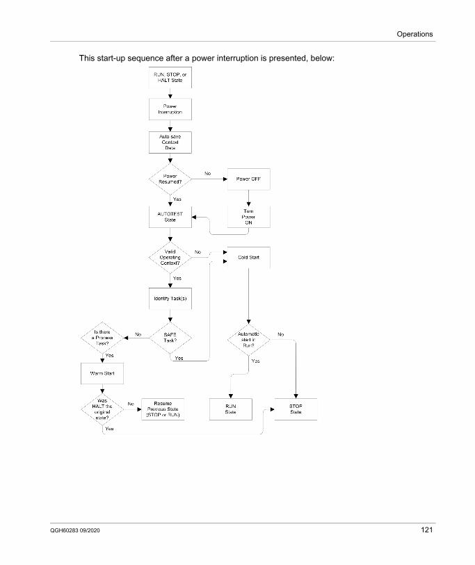
Operations
This start-up sequence after a power interruption is presented, below:
QGH60283 09/2020 121
Operations
Cold StartA cold start causes all tasks, including both the SAFE task and the non-safe (MAST, FAST, AUX0, AUX1) tasks, enter the STOP state, unless Automatic start in RUN is enabled, in which case all tasks enter the RUN state. A cold start performs the following operations: Application data (including internal bits, I/O data, internal words, and so forth) are assigned the
initial values defined by the application. Elementary functions are set to their default values. Elementary function blocks and their variables are set to their default values. System bits and words are set to their default values. Initializes all forced variables by applying their default (initialized) values.A cold start can be executed for data, variables and functions in the process namespace by selecting PLC → Init in Control Expert (see page 139), or by setting the system bit %S0 (COLDSTART) to 1. The %S0 system bit has no effect on the data and functions belonging to the safe namespace.NOTE: Following a cold start, the SAFE task cannot start until after the MAST task has started.
Warm StartA warm start causes each process task – including the (MAST, FAST, AUX0, AUX1) tasks – to re-enter its operating state as of the time of the power interruption. By contrast, a warm start causes the SAFE task to enter the STOP state, unless Automatic start in RUN is selected.NOTE: If a task was in the HALT state or in breakpoint at the time of power interruption, that task enters the STOP state after the warm start.A warm start performs the following operations: Restores the last held value to process namespace variables. Initializes safe namespace variables by applying their default (initialized) values. Initializes all forced variables by applying their default (initialized) values. Restores the last held value to application variables. Sets %S1 (WARMSTART) to 1. Connections between the PAC and CPU are reset. I/O modules are re-configured (if necessary) using their stored settings. Events, the FAST task, and the AUX tasks are disabled. The MAST task is re-started from the beginning of the cycle. %S1 is set to 0 at the conclusion of the first execution of the MAST task. Events, the FAST task, and the AUX tasks are enabled.
122 QGH60283 09/2020
Operations
If a task was in the process of execution at the time of power interruption, after warm start the task resumes execution at the beginning of the task.
WARNINGUNEXPECTED EQUIPMENT OPERATIONYou are responsible to confirm that selecting Automatic start in RUN is compliant with the correct behavior of your system. If it is not, de-activate this feature.Failure to follow these instructions can result in death, serious injury, or equipment damage.
QGH60283 09/2020 123
Operations
M580 Safety PAC Tasks
IntroductionAn M580 safety PAC can execute single-task and multi-task applications. Unlike a single-task application which only executes the MAST task, a multi-task application defines the priority of each task.The M580 safety PAC supports the following tasks: FAST SAFE MAST AUX0 AUX1
Task CharacteristicsThe tasks supported by the M580 safety PAC present the following task characteristics:
Task PriorityM580 Safety PACs execute pending tasks according to their priority. When a task is running, it can be interrupted by another task with a higher relative priority. For example, when a periodic task is scheduled to execute its code, it would interrupt a lower priority task, but would wait until the completion of a higher priority task.
Task Name Priority Time Model Period Range Default Period Watchdog Range Default WatchdogFAST 1 Periodic 1...255 ms 5 ms 10...500 ms2 100 ms2
SAFE 2 Periodic 10...255 ms 20 ms 10...500 ms2 250 ms2
MAST1 3 Cyclic4 or Periodic 1...255 ms 20 ms 10...1500 ms2 250 ms2
AUX03 4 Periodic 10...2550 ms 100 ms 100...5000 ms2 2000 ms2
AUX13 5 Periodic 10...2550 ms 200 ms 100...5000 ms2 2000 ms2
1. MAST task is required and cannot be deactivated.2. If CCOTF is enabled (by selecting Online modification in RUN or STOP in the Configuration tab of the CPU properties dialog), the minimum Watchdog setting is 64 ms.3. Supported by standalone BMEP58•040S safety PACs. Not supported by BMEH58•040S safety Hot Standby PACs.4. Standalone BMEP58•040S safety PACs support both cyclic and periodic time models. BMEH58•040S safety Hot Standby PACs support only the periodic time model.
124 QGH60283 09/2020
Operations
Task Configuration ConsiderationsAll the non-safe tasks (MAST, FAST, AUX0, and AUX1) operate in the same memory area, while the SAFE task operates in its own, separate memory area. As a result: If one non-safe task exceeds its watchdog, all non-safe tasks enter HALT state, while the SAFE
task continues to be operational. If the SAFE task exceeds its watchdog, only the SAFE task enters HALT state, while the non-
safe tasks continue to be operational.When creating and configuring tasks for your application, consider the following task features:SAFE task:Design this periodic task to execute only safety-related code sections for safety I/O modules. Because the SAFE task is assigned a lower priority than the FAST task, execution of the SAFE task may be interrupted by the FAST task.Define the maximum execution time for the SAFE task by setting the appropriate watchdog value. Consider the time required to execute code and to read and write safe data. If the time to execute the SAFE task exceeds the watchdog setting, the SAFE task enters HALT state, and the %SW125 system word displays the detected error code 16#DEB0.NOTE: Because FAST task has a higher priority than the SAFE task, you may want to include a
component for FAST task delay time in the SAFE task watchdog setting. If the overrun of the SAFE task execution equals the “Safety watchdog” (which is a value equal
to one and one-half times the SAFE task watchdog setting), the CPU and Copro will enter the ERROR state and the safety function will be applied.
MAST task:This task can be configured as either cyclic or periodic. When operating in cyclic mode, define a maximum execution time by inputting an appropriate MAST watchdog value. Add a small time interval to this value at the end of each cycle to allow for the execution of other lower priority system tasks. Because the AUX tasks carry a lower priority than MAST, if this time slot is not provided, the AUX tasks may never be executed. Consider adding a time interval equal to 10% of cycle execution time, with a minimum of 1 ms and a maximum of 10 ms.If the time to execute a cyclic MAST task exceeds the watchdog setting, the MAST task and all other non-SAFE tasks enter HALT state, and the %SW125 system word displays the detected error code 16#DEB0.When operating in periodic mode, it is possible for the MAST task to exceed its period. In that case the MAST task runs in cyclic mode and the system bit %S11 is set.
QGH60283 09/2020 125
Operations
FAST task:The purpose of this periodic task is to execute a high-priority part of the application. Define a maximum execution time by setting the FAST watchdog value. Because the FAST task interrupts execution of all other tasks – including the SAFE task – it is recommended to configure the execution time of the FAST task to be as short as possible. A FAST task watchdog value not much greater than the FAST period is recommended.If the time to execute the FAST task exceeds the watchdog setting, the FAST task and all other non-SAFE tasks enter HALT state, and the %SW125 system word displays the detected error code 16#DEB0.AUX tasks:AUX0 and AUX1 are optional periodic tasks. Their purpose is to execute a low priority part of the application. The AUX tasks are executed only after execution of the MAST, SAFE and FAST tasks has finished.Define a maximum execution time for the AUX tasks by setting the appropriate watchdog value. If the time to execute an AUX task exceeds the watchdog setting, the AUX task and all other non-SAFE tasks enter HALT state, and the %SW125 system word displays the detected error code 16#DEB0.
126 QGH60283 09/2020
Operations
Building an M580 Safety Project
Section 8.3Building an M580 Safety Project
What Is in This Section?This section contains the following topics:
Topic PageBuilding an M580 Safety Project 128Safe Signature 129
QGH60283 09/2020 127
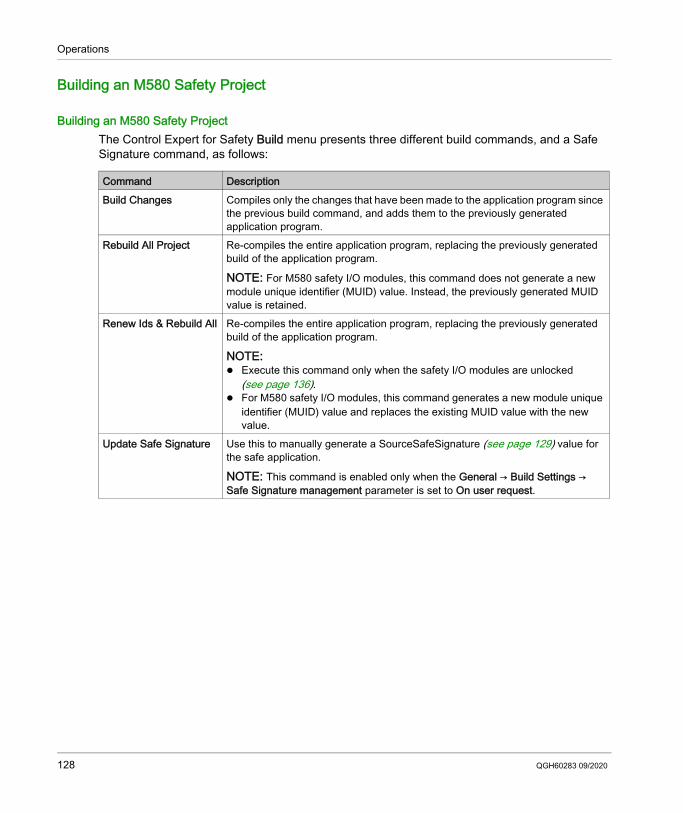
Operations
Building an M580 Safety Project
Building an M580 Safety ProjectThe Control Expert for Safety Build menu presents three different build commands, and a Safe Signature command, as follows:
Command DescriptionBuild Changes Compiles only the changes that have been made to the application program since
the previous build command, and adds them to the previously generated application program.
Rebuild All Project Re-compiles the entire application program, replacing the previously generated build of the application program.
NOTE: For M580 safety I/O modules, this command does not generate a new module unique identifier (MUID) value. Instead, the previously generated MUID value is retained.
Renew Ids & Rebuild All Re-compiles the entire application program, replacing the previously generated build of the application program.
NOTE: Execute this command only when the safety I/O modules are unlocked
(see page 136). For M580 safety I/O modules, this command generates a new module unique
identifier (MUID) value and replaces the existing MUID value with the new value.
Update Safe Signature Use this to manually generate a SourceSafeSignature (see page 129) value for the safe application.
NOTE: This command is enabled only when the General → Build Settings → Safe Signature management parameter is set to On user request.
128 QGH60283 09/2020
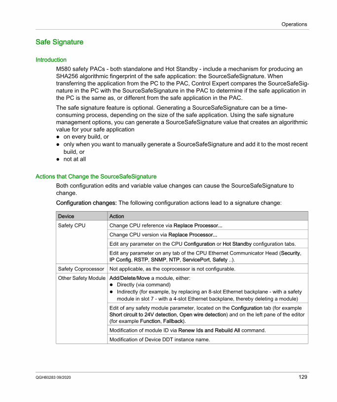
Operations
Safe Signature
IntroductionM580 safety PACs - both standalone and Hot Standby - include a mechanism for producing an SHA256 algorithmic fingerprint of the safe application: the SourceSafeSignature. When transferring the application from the PC to the PAC, Control Expert compares the SourceSafeSig-nature in the PC with the SourceSafeSignature in the PAC to determine if the safe application in the PC is the same as, or different from the safe application in the PAC.The safe signature feature is optional. Generating a SourceSafeSignature can be a time-consuming process, depending on the size of the safe application. Using the safe signature management options, you can generate a SourceSafeSignature value that creates an algorithmic value for your safe application on every build, or only when you want to manually generate a SourceSafeSignature and add it to the most recent
build, or not at all
Actions that Change the SourceSafeSignatureBoth configuration edits and variable value changes can cause the SourceSafeSignature to change.Configuration changes: The following configuration actions lead to a signature change:
Device ActionSafety CPU Change CPU reference via Replace Processor...
Change CPU version via Replace Processor... Edit any parameter on the CPU Configuration or Hot Standby configuration tabs.Edit any parameter on any tab of the CPU Ethernet Communicator Head (Security, IP Config, RSTP, SNMP, NTP, ServicePort, Safety ..).
Safety Coprocessor Not applicable, as the coprocessor is not configurable.Other Safety Module Add/Delete/Move a module, either:
Directly (via command) Indirectly (for example, by replacing an 8-slot Ethernet backplane - with a safety
module in slot 7 - with a 4-slot Ethernet backplane, thereby deleting a module)Edit of any safety module parameter, located on the Configuration tab (for example Short circuit to 24V detection, Open wire detection) and on the left pane of the editor (for example Function, Fallback).Modification of module ID via Renew Ids and Rebuild All command.Modification of Device DDT instance name.
QGH60283 09/2020 129
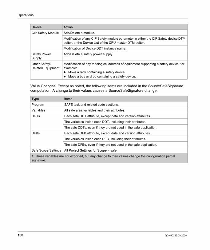
Operations
Value Changes: Except as noted, the following items are included in the SourceSafeSignature computation. A change to their values causes a SourceSafeSignature change:
CIP Safety Module Add/Delete a module.Modification of any CIP Safety module parameter in either the CIP Safety device DTM editor, or the Device List of the CPU master DTM editor.Modification of Device DDT instance name.
Safety Power Supply
Add/Delete a safety power supply.
Other Safety-Related Equipment
Modification of any topological address of equipment supporting a safety device, for example: Move a rack containing a safety device. Move a bus or drop containing a safety device.
Type ItemsProgram SAFE task and related code sections.Variables All safe area variables and their attributes.DDTs Each safe DDT attribute, except date and version attributes.
The variables inside each DDT, including their attributes.The safe DDTs, even if they are not used in the safe application.
DFBs Each safe DFB attribute, except date and version attributes.The variables inside each DFB, including their attributes.The safe DFBs, even if they are not used in the safe application.
Safe Scope Settings All Project Settings for Scope = safe.1. These variables are not exported, but any change to their values change the configuration partial signature.
Device Action
130 QGH60283 09/2020
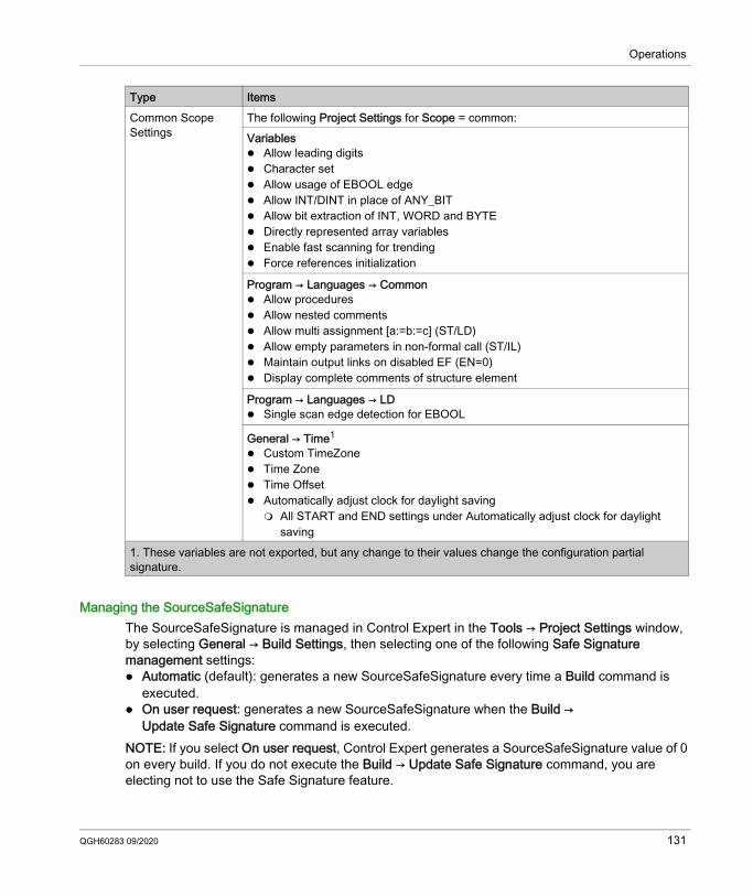
Operations
Managing the SourceSafeSignatureThe SourceSafeSignature is managed in Control Expert in the Tools → Project Settings window, by selecting General → Build Settings, then selecting one of the following Safe Signature management settings: Automatic (default): generates a new SourceSafeSignature every time a Build command is
executed. On user request: generates a new SourceSafeSignature when the Build →
Update Safe Signature command is executed.NOTE: If you select On user request, Control Expert generates a SourceSafeSignature value of 0 on every build. If you do not execute the Build → Update Safe Signature command, you are electing not to use the Safe Signature feature.
Common Scope Settings
The following Project Settings for Scope = common:Variables Allow leading digits Character set Allow usage of EBOOL edge Allow INT/DINT in place of ANY_BIT Allow bit extraction of INT, WORD and BYTE Directly represented array variables Enable fast scanning for trending Force references initialization
Program → Languages → Common Allow procedures Allow nested comments Allow multi assignment [a:=b:=c] (ST/LD) Allow empty parameters in non-formal call (ST/IL) Maintain output links on disabled EF (EN=0) Display complete comments of structure element
Program → Languages → LD Single scan edge detection for EBOOL
General → Time1
Custom TimeZone Time Zone Time Offset Automatically adjust clock for daylight saving All START and END settings under Automatically adjust clock for daylight
saving
Type Items
1. These variables are not exported, but any change to their values change the configuration partial signature.
QGH60283 09/2020 131
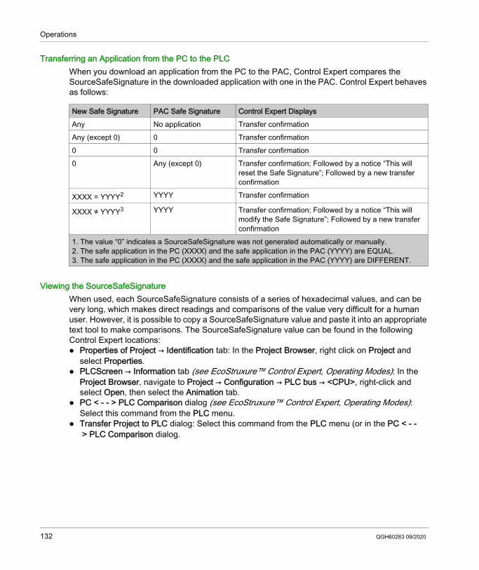
Operations
Transferring an Application from the PC to the PLCWhen you download an application from the PC to the PAC, Control Expert compares the SourceSafeSignature in the downloaded application with one in the PAC. Control Expert behaves as follows:
Viewing the SourceSafeSignatureWhen used, each SourceSafeSignature consists of a series of hexadecimal values, and can be very long, which makes direct readings and comparisons of the value very difficult for a human user. However, it is possible to copy a SourceSafeSignature value and paste it into an appropriate text tool to make comparisons. The SourceSafeSignature value can be found in the following Control Expert locations: Properties of Project → Identification tab: In the Project Browser, right click on Project and
select Properties. PLCScreen → Information tab (see EcoStruxure™ Control Expert, Operating Modes): In the
Project Browser, navigate to Project → Configuration → PLC bus → <CPU>, right-click and select Open, then select the Animation tab.
PC < - - > PLC Comparison dialog (see EcoStruxure™ Control Expert, Operating Modes): Select this command from the PLC menu.
Transfer Project to PLC dialog: Select this command from the PLC menu (or in the PC < - -> PLC Comparison dialog.
New Safe Signature PAC Safe Signature Control Expert DisplaysAny No application Transfer confirmationAny (except 0) 0 Transfer confirmation0 0 Transfer confirmation0 Any (except 0) Transfer confirmation; Followed by a notice “This will
reset the Safe Signature”; Followed by a new transfer confirmation
XXXX = YYYY2 YYYY Transfer confirmation
XXXX ≠ YYYY3 YYYY Transfer confirmation; Followed by a notice “This will modify the Safe Signature”; Followed by a new transfer confirmation
1. The value “0” indicates a SourceSafeSignature was not generated automatically or manually.2. The safe application in the PC (XXXX) and the safe application in the PAC (YYYY) are EQUAL.3. The safe application in the PC (XXXX) and the safe application in the PAC (YYYY) are DIFFERENT.
132 QGH60283 09/2020
Operations
Comparing the SourceSafeSignature and the SAIdThe SourceSafeSignature was introduced to provide an a priori verification that the safe application is unchanged. It is recommended to use this feature each time the process application is modified (see page 134) to avoid unintended modification of the safe application.The SourceSafeSignature is a reliable mechanism, but is not sufficient for safety applications because the same source code may correspond to different binary (executable) codes, depending on the kind of build used after the last modification of the safe code.The SAId can be evaluated only at run time. Its calculation is double executed and compared by both the CPU and the COPRO, based on the binary code that is executed by the safe application. Because the SAId is sensitive to all modifications, including those that may be introduced by a Rebuild All command after a build change, it is recommended that you use a Rebuild All command to generate a reference version of the safe application. This process (see page 135) lets you use any form of build (Rebuild All, Build Changes online or offline) for the process application changes without any change made to the SAId.The SAId is the recommended method used to confirm that the safe application is the one that was validated. The SAId value is not automatically tested by the application. For this reason, it is recommended that you regularly verify the SAId by any convenient mean (for example, using Control Expert or an HMI) by reading the output of the S_SYST_STAT_MX function block or the content of system word %SW169 (see page 202).
QGH60283 09/2020 133
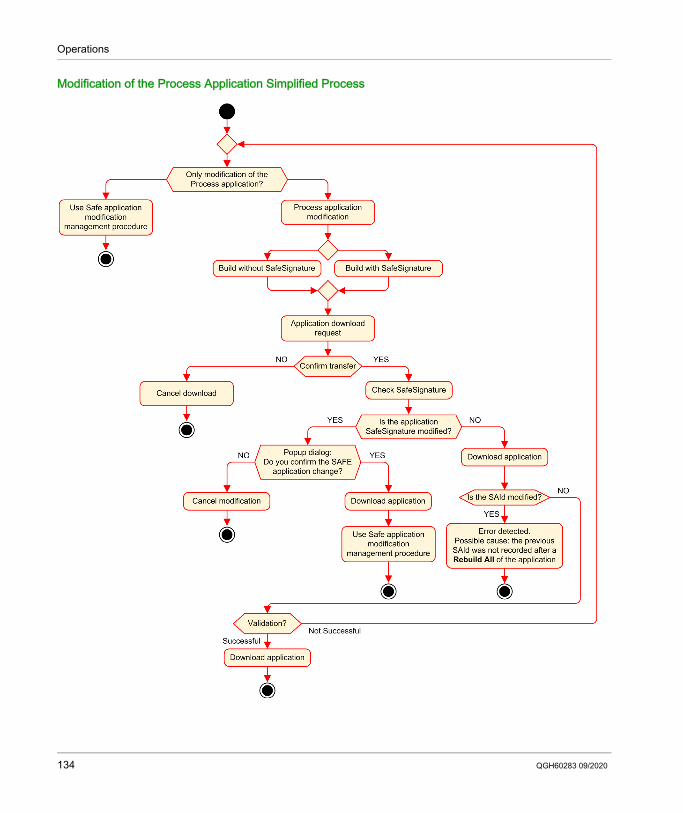
Operations
Modification of the Process Application Simplified Process
134 QGH60283 09/2020
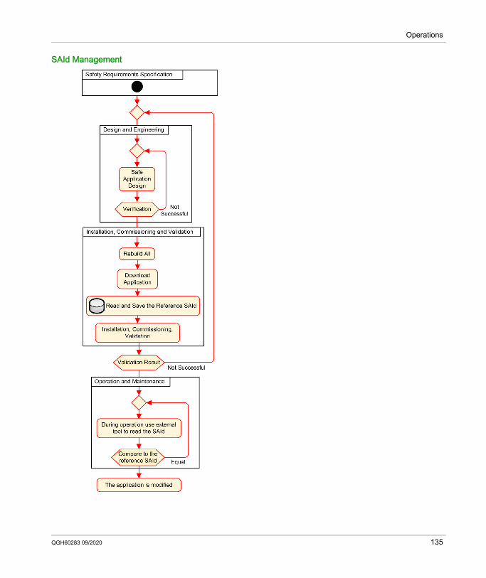
Operations
SAId Management
QGH60283 09/2020 135
Operations
Locking M580 Safety I/O Module Configurations
Section 8.4Locking M580 Safety I/O Module Configurations
Locking M580 Safety I/O Module Configurations
Locking a Safety I/O Module ConfigurationEach safety I/O module has a configuration locking button (see page 65), which you can find at the top front of the module. The purpose of the locking function is to help prevent unintended changes to I/O module configuration. For example, locking the I/O module's current configuration can stop an attempt to assign the module a fake configuration, or merely help protect against configuration mistakes.To achieve the intended safety integrity level (SIL), lock each safety I/O module after it has been configured, but before you begin or resume operations.
The lock and unlock mechanisms work as follows: To lock a safety I/O module configuration, press and hold down the lock button for more than
3 seconds, then release the button. To unlock a safety I/O module configuration, press and hold down the lock button for more than
3 seconds, then release the button.
WARNINGRISK OF UNINTENDED DEGRADATION TO PROJECT SAFETY INTEGRITY LEVELYou must lock each safety I/O module after it is configured but before beginning operations.Failure to follow these instructions can result in death, serious injury, or equipment damage.
136 QGH60283 09/2020
Operations
Scenarios for Locking Safety I/O Module configurationsThe procedure you follow to lock the configuration of SIL3 safety I/O modules will vary, depending on the scenario, which can be: First configuration of the I/O modules Fast device replacement of I/O modules Perform a change configuration on the fly (CCOTF) for I/O modulesThe procedure for each scenario is described below.First configuration of SIL3 I/O safety modules:
Fast device replacement of a SIL3 I/O safety module:
Step Action1 Connect Control Expert to the M580 safety PAC.2 Use the Transfer project from PLC command to load the project from the PAC into Control Expert.3 In the PLC bus window in Control Expert, open each SIL3 safety I/O module and confirm that each
module is accurately configured.4 In an animation table in Control Expert, view the DDDT for each SIL3 safety I/O module and confirm
that the configuration of each module is the same as in step 3, above.5 Lock the configuration of each SIL3 I/O module by pressing and holding down the configuration
locking button (see page 65) for more than 3 seconds, then release the button.6 Check in an animation table the validity of the lock bit status (CONF_LOCKED) for each SIL3 I/O
module.
Step Action1 Replace the SIL3 safety I/O module with a new one. 2 Connect Control Expert to the M580 safety PAC in maintenance operating mode (see page 111).3 In the PLC bus window in Control Expert, open each SIL3 safety I/O module and confirm that each
module is accurately configured.4 In an animation table in Control Expert, view the DDDT for each SIL3 safety I/O module and confirm
that the configuration of each module has not changed and is the same as in step 3, above.5 Lock the configuration of each SIL3 I/O module by pressing and holding down the configuration
locking button (see page 65) for more than 3 seconds, then release the button.6 Check in an animation table the validity of the lock bit status (CONF_LOCKED) for each SIL3 I/O
module.
QGH60283 09/2020 137
Operations
Performing CCOTF to add a new SIL3 I/O safety module:
Step Action1 Connect Control Expert to the M580 safety PAC in maintenance operating mode (see page 111).2 Add a new SIL3 safety I/O module to the configuration, and edit the module settings if necessary. 3 Execute the Build → Build Changes command.4 In the PLC bus window in Control Expert, open each SIL3 safety I/O module and confirm that each
module is accurately configured.5 In an animation table in Control Expert, view the DDDT for each SIL3 safety I/O module and confirm
that the configuration of each module has not changed and is the same as in step 3, above.6 Lock the configuration of each SIL3 I/O module by pressing and holding down the configuration
locking button (see page 65) for more than 3 seconds, then release the button.7 Check in an animation table the validity of the lock bit status (CONF_LOCKED) for each SIL3 I/O
module.8 In the PLC menu of Control Expert, command the PAC to enter safety mode (see page 110).
138 QGH60283 09/2020
Operations
Initializing Data in Control Expert
Section 8.5Initializing Data in Control Expert
Initializing Data in Control Expert for the M580 Safety PAC
Two Init CommandsThe PLC menu in Control Expert provides two separate commands for the initialization of data: The Init command initializes data for the process (or non-safe) namespace, which can be used
by the MAST, FAST, AUX0 and AUX1 tasks. You can execute this command if the PAC is operating in either safety or maintenance mode while the PAC is in the STOP state. This command is the equivalent of setting the system bit %S0 (COLDSTART) to 1.NOTE: Setting the %S0 bit to 1 initializes data in the process namespace only. It does not affect data in the safe namespace.
The Init Safety command initializes data only for the safe namespace, which data can be used exclusively by the SAFE task. You can execute this command only if the SAFE task is operating in maintenance mode while the SAFE task is in the STOP or HALT state. Executing this command when the SAFE task is in the HALT state causes the SAFE task to restart in the STOP state.
Both the Init and the Init Safety commands perform a cold start. (see page 122)
QGH60283 09/2020 139
Operations
Working with Animation Tables in Control Expert
Section 8.6Working with Animation Tables in Control Expert
Animation Tables and Operator Screens
IntroductionA M580 safety PAC supports three kinds of animation tables, each associated with one of the following data areas: Process area animation tables can include only data in the process namespace. Safety area animation tables can include only data in the safe namespace. Global animation tables can include data for the entire application, including data created for the
safe and process namespaces, and global variables.NOTE: In a global animation table, data variable names include a prefix indicating the source namespace, as follows:
A data variable from the Safe namespace is displayed as “SAFE.<varname>”. A data variable from the Process namespace is displayed as “PROCESS.<variable name>”. A data variable from the Global (or Application) namespace displays only its <variable name>,
with no namespace prefix.Both process and safety data from an M580 safety PAC are also accessible by external processes (for example, SCADA or HMI).Your ability to create and modify an animation table, and the ability to execute animation table functions, depend on the namespace of the affected variables and the operating mode of the safety project.
140 QGH60283 09/2020
Operations
Conditions for Creating and Editing Animation TablesCreating and editing animation tables involves adding or deleting data variables. Your ability to add data variables to, or delete data variables from an animation table depends on: The namespace (safe or process) in which the data variable resides. The operating mode (safety or maintenance) of the M580 safety PAC.When Control Expert is connected to the M580 safety PAC, you can create and edit animation tables as follows: Adding process namespace variables to, or deleting process namespace variables from a
process or global animation table is supported while the M580 safety PAC is operating in either safety mode or maintenance mode.
Adding safe namespace variables to, or deleting safe namespace variables from a safety animation table is supported while the M580 safety PAC is operating in maintenance mode.
Adding safe namespace variables to, or deleting safe namespace variables from a safety animation table is supported while the M580 safety PAC is operating in safety mode only if the project settings do not include animation tables in the upload information.NOTE: Animation tables are included in, or excluded from, upload information in Control Expert by selecting Tools → Project Settings... to open the Project Settings... window, then navigating to Project Settings → General → PLC embedded data → Upload information → Animation tables.
Conditions for Operating Animation TablesYou can use animation tables to force a variable value, unforce a variable value, modify a single variable value, or modify multiple variable values. Your ability to perform these functions depends on the namespace in which a variable resides and the operating mode of the M580 safety PAC, as follows: Process or global variable values can be read or written in both safety operating mode and
maintenance operating mode. Safety variable values can be read or written in maintenance operating mode. Safety variable values can only be read in safety operating mode.
QGH60283 09/2020 141
Operations
Process for Creating Animation Tables in the Safety or Process Namespace in Control ExpertControl Expert provides two ways to create animation tables for either the safety or process namespace: From a safety or process code section window, right click in the code window, then select either: Initialize Animation Table to add the data object to an existing animation table in safety or
process namespace, or Initialize New Animation Table to add the data object to a new animation table in the safety
or process namespace.In each case, all the variables in the code section are added to the existing or new animation table.
From the Project Browser, in either the process or safety data area, right click on the Animation Tables folder, then select New Animation Table. Control Expert creates a new, empty animation table. You can then add individual variables from the namespace (safety or process) related to the table.
Process for Creating Globally Scoped Animation TablesCreate a global animation table in the Project Browser by right clicking the global Animation Tables folder, then selecting New Animation Table. You can add variables to the new animation table in several ways: Drag and drop: You can drag a variable from a data editor and drop it into the global animation
table. Because the scope of the animation table includes the entire application, you can drag the variable from the Safety Data Editor, the Process Data Editor, or the Global Data Editor.
Instance Selection dialog: You can double-click in a row in the animation table, then click the ellipsis button to open the Instance Selection dialog. Use the filtering list in the top right part of the dialog to select a one of the following project areas: SAFE: to display data objects associated with the safety area. PROCESS: to display data object associated with the process area. APPLICATION: to display higher-level application scope data objects.Select a data object, then click OK to add the item to the animation table.
NOTE: Data objects added to a global animation table from the: Process area have the prefix “PROCESS” affixed to the variable name (for example
PROCESS.variable_01 Safety area have the prefix “SAFE” affixed to the variable name (for example SAFE.variable_02 Global area have no such prefix added to the variable name.
142 QGH60283 09/2020
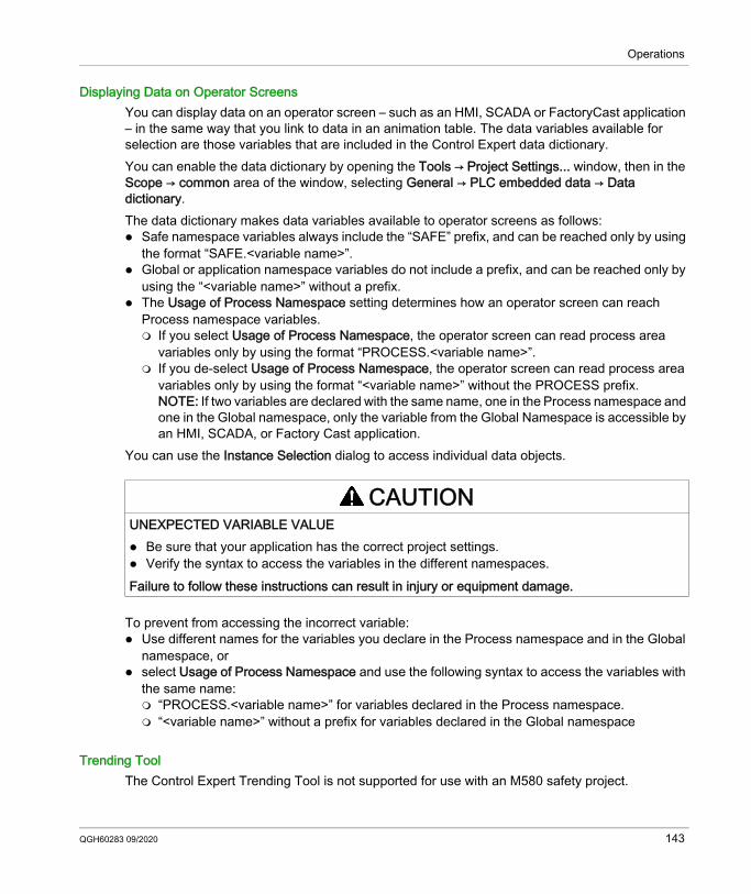
Operations
Displaying Data on Operator ScreensYou can display data on an operator screen – such as an HMI, SCADA or FactoryCast application – in the same way that you link to data in an animation table. The data variables available for selection are those variables that are included in the Control Expert data dictionary.You can enable the data dictionary by opening the Tools → Project Settings... window, then in the Scope → common area of the window, selecting General → PLC embedded data → Data dictionary.The data dictionary makes data variables available to operator screens as follows: Safe namespace variables always include the “SAFE” prefix, and can be reached only by using
the format “SAFE.<variable name>”. Global or application namespace variables do not include a prefix, and can be reached only by
using the “<variable name>” without a prefix. The Usage of Process Namespace setting determines how an operator screen can reach
Process namespace variables. If you select Usage of Process Namespace, the operator screen can read process area
variables only by using the format “PROCESS.<variable name>”. If you de-select Usage of Process Namespace, the operator screen can read process area
variables only by using the format “<variable name>” without the PROCESS prefix.NOTE: If two variables are declared with the same name, one in the Process namespace and one in the Global namespace, only the variable from the Global Namespace is accessible by an HMI, SCADA, or Factory Cast application.
You can use the Instance Selection dialog to access individual data objects.
To prevent from accessing the incorrect variable: Use different names for the variables you declare in the Process namespace and in the Global
namespace, or select Usage of Process Namespace and use the following syntax to access the variables with
the same name: “PROCESS.<variable name>” for variables declared in the Process namespace. “<variable name>” without a prefix for variables declared in the Global namespace
Trending ToolThe Control Expert Trending Tool is not supported for use with an M580 safety project.
CAUTIONUNEXPECTED VARIABLE VALUE Be sure that your application has the correct project settings. Verify the syntax to access the variables in the different namespaces.Failure to follow these instructions can result in injury or equipment damage.
QGH60283 09/2020 143
Operations
Adding Code Sections
Section 8.7Adding Code Sections
What Is in This Section?This section contains the following topics:
Topic PageAdding Code to an M580 Safety Project 145Diagnostic Request 149Swap and Clear Commands 152
144 QGH60283 09/2020
Operations
Adding Code to an M580 Safety Project
Working with Tasks in Control ExpertIn the process namespace, Control Expert includes the MAST task by default. The MAST task cannot be removed. However, you can add the tasks FAST, AUX0, and AUX1. Note that creating a task in the process part of a safety project is the same as creating a task in a non-safety project. Refer to the topic Create and Configure a Task in the EcoStruxure™ Control Expert Operating Modes manual for more information.In the safe namespace, Control Expert includes the SAFE task by default. The SAFE task cannot be removed, and no other tasks can be added to the Program Safety section of the Project Browser in Control Expert. You can add multiple sections to the SAFE task.
Configuring the SAFE Task PropertiesThe SAFE task supports only periodic task execution (cyclic execution is not supported). Both the SAFE task Period and Watch Dog settings are input in the Properties of SAFE dialog and can support the following value range: SAFE task period: 10...255 ms with a default of 20 ms. SAFE task watchdog: 10...500 ms, in increments of 10 ms, with a default of 250 ms.Set the SAFE task Period to a minimum value depending on the safe data size and the PLC model. The minimum SAFE task period can be calculated according to the following formulas: Absolute minimum necessary for safe I/O communication: 10 ms
Time (in ms) necessary to transfer and compare the safe data between the CPU and the COPRO: (0.156 x Data_Safe_Size) + 2 ms (for BMEP584040S, BMEH584040S, and BMEH586040S) (0.273 x Data_Safe_Size) + 2 ms (for BMEP582040S and BMEH582040S)Where the Data_Safe_Size is the size in Kbytes of the safe data.
QGH60283 09/2020 145
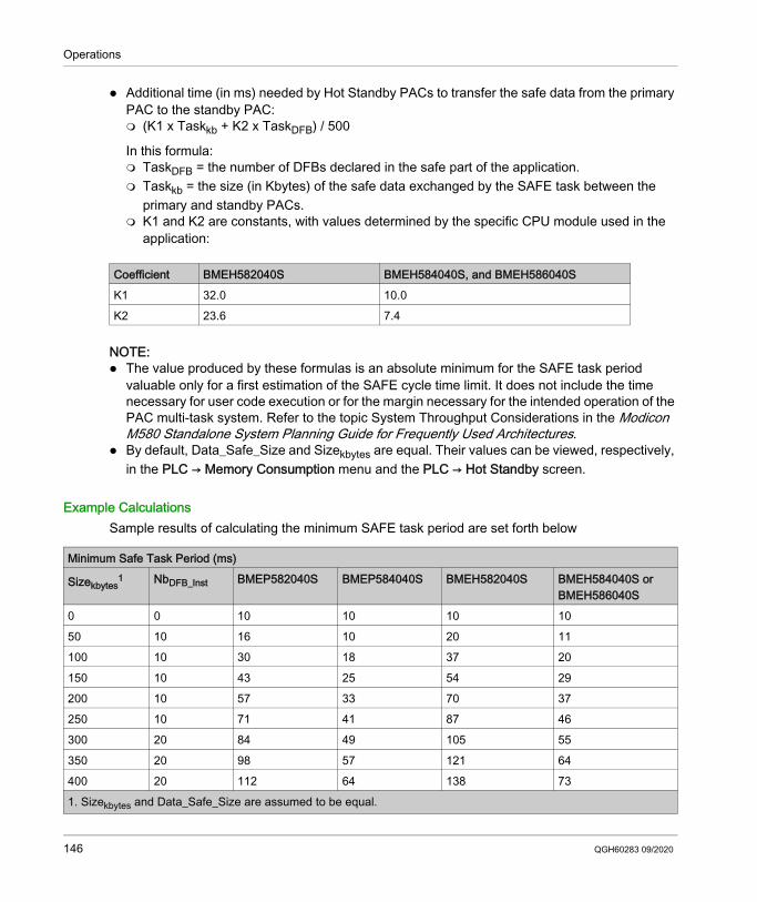
Operations
Additional time (in ms) needed by Hot Standby PACs to transfer the safe data from the primary PAC to the standby PAC: (K1 x Taskkb + K2 x TaskDFB) / 500
In this formula: TaskDFB = the number of DFBs declared in the safe part of the application. Taskkb = the size (in Kbytes) of the safe data exchanged by the SAFE task between the
primary and standby PACs. K1 and K2 are constants, with values determined by the specific CPU module used in the
application:
NOTE: The value produced by these formulas is an absolute minimum for the SAFE task period
valuable only for a first estimation of the SAFE cycle time limit. It does not include the time necessary for user code execution or for the margin necessary for the intended operation of the PAC multi-task system. Refer to the topic System Throughput Considerations in the Modicon M580 Standalone System Planning Guide for Frequently Used Architectures.
By default, Data_Safe_Size and Sizekbytes are equal. Their values can be viewed, respectively, in the PLC → Memory Consumption menu and the PLC → Hot Standby screen.
Example CalculationsSample results of calculating the minimum SAFE task period are set forth below
Coefficient BMEH582040S BMEH584040S, and BMEH586040SK1 32.0 10.0K2 23.6 7.4
Minimum Safe Task Period (ms)
Sizekbytes1 NbDFB_Inst BMEP582040S BMEP584040S BMEH582040S BMEH584040S or
BMEH586040S0 0 10 10 10 1050 10 16 10 20 11100 10 30 18 37 20150 10 43 25 54 29200 10 57 33 70 37250 10 71 41 87 46300 20 84 49 105 55350 20 98 57 121 64400 20 112 64 138 731. Sizekbytes and Data_Safe_Size are assumed to be equal.
146 QGH60283 09/2020
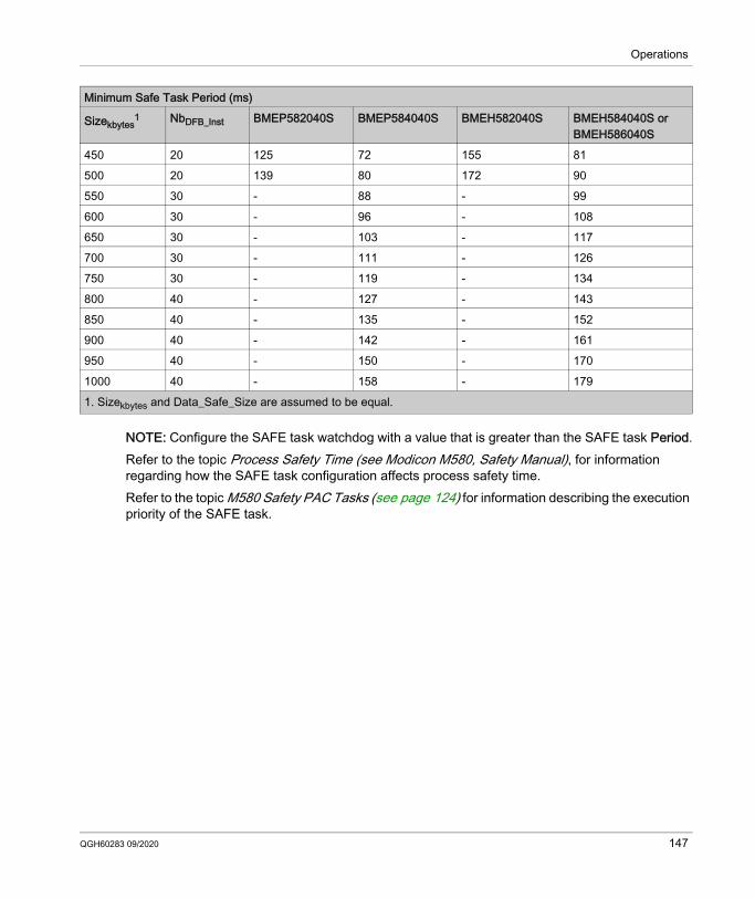
Operations
NOTE: Configure the SAFE task watchdog with a value that is greater than the SAFE task Period.Refer to the topic Process Safety Time (see Modicon M580, Safety Manual), for information regarding how the SAFE task configuration affects process safety time.Refer to the topic M580 Safety PAC Tasks (see page 124) for information describing the execution priority of the SAFE task.
450 20 125 72 155 81500 20 139 80 172 90550 30 - 88 - 99600 30 - 96 - 108650 30 - 103 - 117700 30 - 111 - 126750 30 - 119 - 134800 40 - 127 - 143850 40 - 135 - 152900 40 - 142 - 161950 40 - 150 - 1701000 40 - 158 - 179
Minimum Safe Task Period (ms)
Sizekbytes1 NbDFB_Inst BMEP582040S BMEP584040S BMEH582040S BMEH584040S or
BMEH586040S
1. Sizekbytes and Data_Safe_Size are assumed to be equal.
QGH60283 09/2020 147
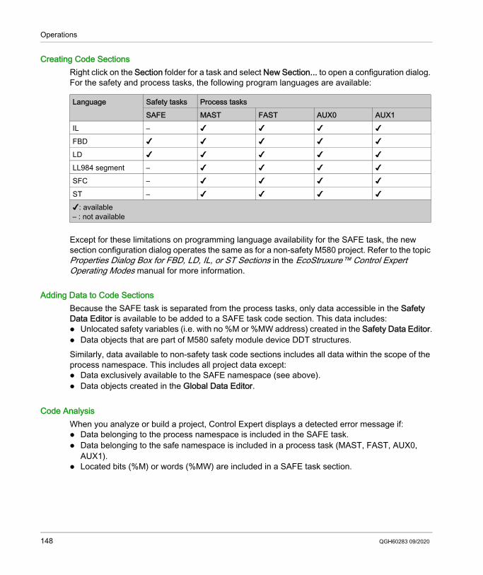
Operations
Creating Code SectionsRight click on the Section folder for a task and select New Section... to open a configuration dialog. For the safety and process tasks, the following program languages are available:
Except for these limitations on programming language availability for the SAFE task, the new section configuration dialog operates the same as for a non-safety M580 project. Refer to the topic Properties Dialog Box for FBD, LD, IL, or ST Sections in the EcoStruxure™ Control Expert Operating Modes manual for more information.
Adding Data to Code SectionsBecause the SAFE task is separated from the process tasks, only data accessible in the Safety Data Editor is available to be added to a SAFE task code section. This data includes: Unlocated safety variables (i.e. with no %M or %MW address) created in the Safety Data Editor. Data objects that are part of M580 safety module device DDT structures.Similarly, data available to non-safety task code sections includes all data within the scope of the process namespace. This includes all project data except: Data exclusively available to the SAFE namespace (see above). Data objects created in the Global Data Editor.
Code AnalysisWhen you analyze or build a project, Control Expert displays a detected error message if: Data belonging to the process namespace is included in the SAFE task. Data belonging to the safe namespace is included in a process task (MAST, FAST, AUX0,
AUX1). Located bits (%M) or words (%MW) are included in a SAFE task section.
Language Safety tasks Process tasksSAFE MAST FAST AUX0 AUX1
IL – ✔ ✔ ✔ ✔FBD ✔ ✔ ✔ ✔ ✔LD ✔ ✔ ✔ ✔ ✔LL984 segment – ✔ ✔ ✔ ✔SFC – ✔ ✔ ✔ ✔ST – ✔ ✔ ✔ ✔✔: available– : not available
148 QGH60283 09/2020
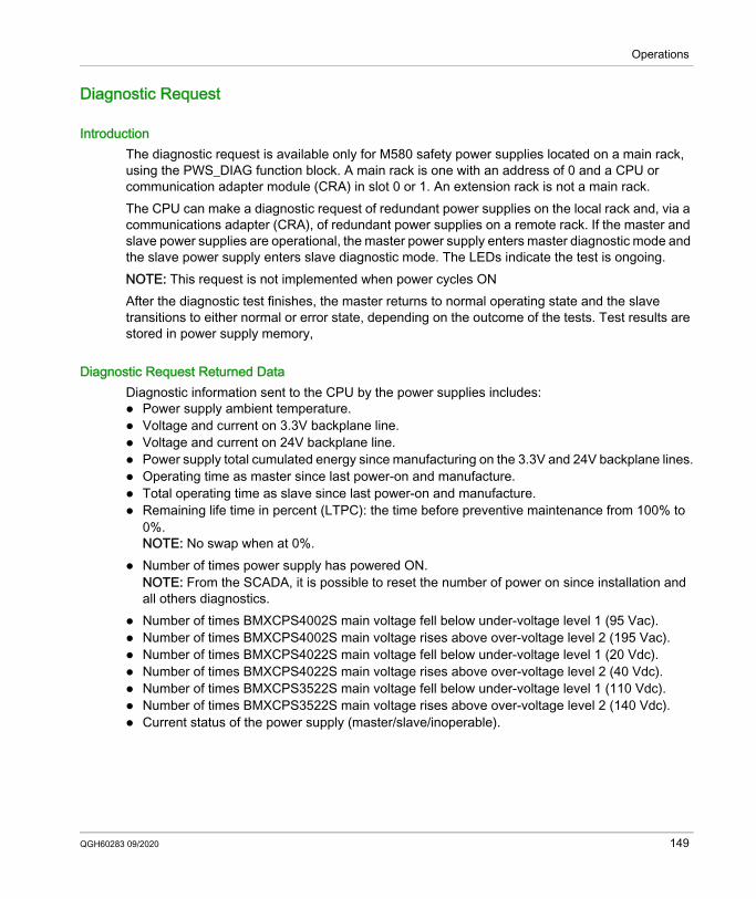
Operations
Diagnostic Request
IntroductionThe diagnostic request is available only for M580 safety power supplies located on a main rack, using the PWS_DIAG function block. A main rack is one with an address of 0 and a CPU or communication adapter module (CRA) in slot 0 or 1. An extension rack is not a main rack.The CPU can make a diagnostic request of redundant power supplies on the local rack and, via a communications adapter (CRA), of redundant power supplies on a remote rack. If the master and slave power supplies are operational, the master power supply enters master diagnostic mode and the slave power supply enters slave diagnostic mode. The LEDs indicate the test is ongoing.NOTE: This request is not implemented when power cycles ONAfter the diagnostic test finishes, the master returns to normal operating state and the slave transitions to either normal or error state, depending on the outcome of the tests. Test results are stored in power supply memory,
Diagnostic Request Returned DataDiagnostic information sent to the CPU by the power supplies includes: Power supply ambient temperature. Voltage and current on 3.3V backplane line. Voltage and current on 24V backplane line. Power supply total cumulated energy since manufacturing on the 3.3V and 24V backplane lines. Operating time as master since last power-on and manufacture. Total operating time as slave since last power-on and manufacture. Remaining life time in percent (LTPC): the time before preventive maintenance from 100% to
0%.NOTE: No swap when at 0%.
Number of times power supply has powered ON.NOTE: From the SCADA, it is possible to reset the number of power on since installation and all others diagnostics.
Number of times BMXCPS4002S main voltage fell below under-voltage level 1 (95 Vac). Number of times BMXCPS4002S main voltage rises above over-voltage level 2 (195 Vac). Number of times BMXCPS4022S main voltage fell below under-voltage level 1 (20 Vdc). Number of times BMXCPS4022S main voltage rises above over-voltage level 2 (40 Vdc). Number of times BMXCPS3522S main voltage fell below under-voltage level 1 (110 Vdc). Number of times BMXCPS3522S main voltage rises above over-voltage level 2 (140 Vdc). Current status of the power supply (master/slave/inoperable).
QGH60283 09/2020 149
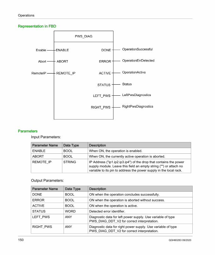
Operations
Representation in FBD
ParametersInput Parameters:
Output Parameters:
Parameter Name Data Type DescriptionENABLE BOOL When ON, the operation is enabled.ABORT BOOL When ON, the currently active operation is aborted.REMOTE_IP STRING IP Address ("ip1.ip2.ip3.ip4") of the drop that contains the power
supply module. Leave this field an empty string ("") or attach no variable to its pin to address the power supply in the local rack.
Parameter Name Data Type DescriptionDONE BOOL ON when the operation concludes successfully.ERROR BOOL ON when the operation is aborted without success.ACTIVE BOOL ON when the operation is active.STATUS WORD Detected error identifier.LEFT_PWS ANY Diagnostic data for left power supply. Use variable of type
PWS_DIAG_DDT_V2 for correct interpretation.RIGHT_PWS ANY Diagnostic data for right power supply. Use variable of type
PWS_DIAG_DDT_V2 for correct interpretation.
150 QGH60283 09/2020
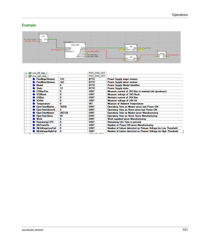
Operations
Example
QGH60283 09/2020 151
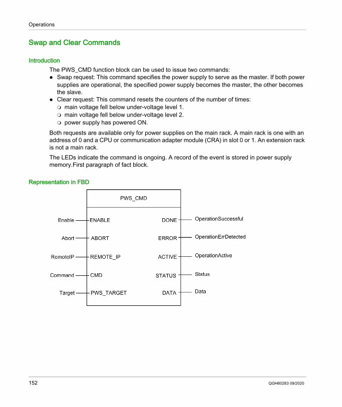
Operations
Swap and Clear Commands
IntroductionThe PWS_CMD function block can be used to issue two commands: Swap request: This command specifies the power supply to serve as the master. If both power
supplies are operational, the specified power supply becomes the master, the other becomes the slave.
Clear request: This command resets the counters of the number of times: main voltage fell below under-voltage level 1. main voltage fell below under-voltage level 2. power supply has powered ON.
Both requests are available only for power supplies on the main rack. A main rack is one with an address of 0 and a CPU or communication adapter module (CRA) in slot 0 or 1. An extension rack is not a main rack. The LEDs indicate the command is ongoing. A record of the event is stored in power supply memory.First paragraph of fact block.
Representation in FBD
152 QGH60283 09/2020
Operations
ParametersInput Parameters:
Output Parameters:
Parameter Name Data Type DescriptionENABLE BOOL When ON, the operation is enabled.ABORT BOOL When ON, the currently active operation is aborted.REMOTE_IP STRING IP Address ("ip1.ip2.ip3.ip4") of the drop that contains the power
supply module. Leave this field an empty string ("") or attach no variable to its pin to address the power supply in the local rack.
CMD ANY Use variable of type PWS_CMD_DDT for correct interpretation. Available command code: 1 = swap 3 = clear
PWS_TARGET BYTE Power supply to address: 1 = left 2 = right 3 = both
Parameter Name Data Type DescriptionDONE BOOL ON when the operation concludes successfully.ERROR BOOL ON when the operation is aborted without success.ACTIVE BOOL ON when the operation is active.STATUS WORD Detected error identifier.DATA ANY Response data (depending of command code). No data are reported
for swap and clear commands.
QGH60283 09/2020 153
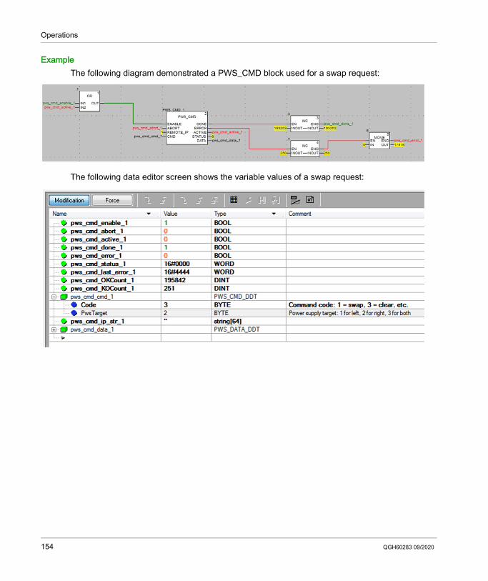
Operations
ExampleThe following diagram demonstrated a PWS_CMD block used for a swap request:
The following data editor screen shows the variable values of a swap request:
154 QGH60283 09/2020
Operations
Application Security Management
Section 8.8Application Security Management
IntroductionControl Expert lets you restrict access to the M580 safety PAC to users with assigned passwords. This section references the password assignment processes available in Control Expert.
What Is in This Section?This section contains the following topics:
Topic PageApplication Password Protection 156Safe Area Password Protection 160Section Protection 163Firmware Protection 165Data Storage Protection 167Loss of Password 169
QGH60283 09/2020 155
Operations
Application Password Protection
OverviewControl Expert provides a password mechanism to help guard against unauthorized access to the application. Control Expert uses the password when you: Open the application in Control Expert. Connect to the PAC in Control Expert.NOTE: Use of a password is optional. The application protection by password mechanism is disabled if no password is configured in the application (the default setting).Application protection by password helps prevent unwanted application modification, download, or the opening of (.STU and .STA files). The password is stored encrypted in the application.
Application PasswordAn M580 safety project is not password protected by default. If you do not manually assign a password when you create the safety project, Control Expert applies an empty string as the password.In this case, when you next open your Control Expert M580 safety project, the Password dialog opens. To access your project, enter no password text, thereby accepting the empty string, and click OK. Thereafter, you can follow the steps set forth below to create a new password.It is possible to create or change a password at any time. The password is case-sensitive and has a length from 8 to 16 characters. The password robustness is increased when it contains a mix of upper and lower case, alphabetical, numerical, and special characters.
Creating a PasswordProcedure for creating the application protection password:
Step Action1 In the project browser right-click Project.2 Select Properties command from the popup menu.
Result: The Properties of Project window appears.3 Select the Project & Controller Protection tab.4 In the Application field, click Change password ....
Result: The Modify Password window appears.5 Enter the new password in the Entry field.6 Enter the confirmation of the new password in the Confirmation field.7 Click OK to confirm.8 Click OK or Apply in the Properties of Project window to confirm all changes.
If you click Cancel in the Properties of Project window, all changes are canceled.
156 QGH60283 09/2020
Operations
Changing the PasswordProcedure for changing the application protection password:
Deleting the PasswordProcedure for clearing the application protection password:
Step Action1 In the project browser right-click Project.2 Select Properties command from the popup menu.
Result: The Properties of Project window appears.3 Select the Project & Controller Protection tab.4 In the Application field, click Change password ....
Result: The Modify Password window appears.5 Enter previous password in the Old password field.6 Enter the new password in the Entry field.7 Enter the confirmation of the new password in the Confirmation field.8 Click OK to confirm.9 Click OK or Apply in the Properties of Project window to confirm all changes.
If you click Cancel in the Properties of Project window, all changes are canceled.
Step Action1 In the project browser right-click Project.2 Select Properties command from the popup menu.
Result: The Properties of Project window appears.3 Select the Project & Controller Protection tab.4 In the Application field, click Clear password....
Result: The Password window appears.5 Enter the password in the Password field.6 Click OK to confirm.7 Click OK or Apply in the Properties of Project window to confirm all changes.
If you click Cancel in the Properties of Project window, all changes are canceled.
QGH60283 09/2020 157
Operations
Auto-Lock FeatureThere is an optional auto-lock feature that limits access to the Control Expert software programming tool after a configured time of inactivity. You can activate the auto-lock feature with the check box Auto-lock and select the time-out for the time of inactivity via Minutes before lock.The default values are: Auto-lock is not activated Minutes before lock is set to 10 minutes (possible values: 1...999 minutes)If the auto-lock feature is enabled and the configured inactivity time elapses, a modal dialog box is displayed requiring the entry of the application password. Behind the modal dialog box, all opened editors remain open in the same position. As a result, anybody can read the current content of the Control Expert windows but cannot continue to work with Control Expert.NOTE: If you have not assigned a password to the project, the modal dialog box is not displayed.
Password Request ConditionOpen an existing application (project) in Control Expert:
Accessing the application in Control Expert after an auto-lock, when Control Expert is not connected to the PAC or when the project in Control Expert is EQUAL to the project in the PAC:
Password ManagementWhen an application file is opened, an Application Password dialog box opens.Enter the password.Click OK. If the password is correct, the application opens.
If the password is wrong, a message box indicates an incorrect password was entered, and a new Application Password dialog box opens.
If you click Cancel, the application is not opened
Password ManagementWhen auto-lock time is elapsed, an Application Password dialog box opens:Enter the password.Click OK. If the password is correct, Control Expert becomes active again.
If the password is wrong, a message box indicates an incorrect password was entered, and a new Application Password dialog box opens.
If you click Close, the application is closed without being saved.
158 QGH60283 09/2020
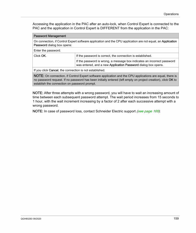
Operations
Accessing the application in the PAC after an auto-lock, when Control Expert is connected to the PAC and the application in Control Expert is DIFFERENT from the application in the PAC:
NOTE: After three attempts with a wrong password, you will have to wait an increasing amount of time between each subsequent password attempt. The wait period increases from 15 seconds to 1 hour, with the wait increment increasing by a factor of 2 after each successive attempt with a wrong password.NOTE: In case of password loss, contact Schneider Electric support (see page 169).
Password ManagementOn connection, if Control Expert software application and the CPU application are not equal, an Application Password dialog box opens:Enter the password.Click OK. If the password is correct, the connection is established.
If the password is wrong, a message box indicates an incorrect password was entered, and a new Application Password dialog box opens.
If you click Cancel, the connection is not established.
NOTE: On connection, if Control Expert software application and the CPU applications are equal, there is no password request. If no password has been initially entered (left empty on project creation), click OK to establish the connection on password prompt.
QGH60283 09/2020 159
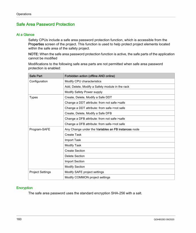
Operations
Safe Area Password Protection
At a GlanceSafety CPUs include a safe area password protection function, which is accessible from the Properties screen of the project. This function is used to help protect project elements located within the safe area of the safety project.NOTE: When the safe area password protection function is active, the safe parts of the application cannot be modified Modifications to the following safe area parts are not permitted when safe area password protection is enabled:
EncryptionThe safe area password uses the standard encryption SHA-256 with a salt.
Safe Part Forbidden action (offline AND online)Configuration Modify CPU characteristics
Add, Delete, Modify a Safety module in the rackModify Safety Power supply
Types Create, Delete, Modify a Safe DDTChange a DDT attribute: from not safe->safeChange a DDT attribute: from safe->not safeCreate, Delete, Modify a Safe DFBChange a DFB attribute: from not safe->safeChange a DFB attribute: from safe->not safe
Program-SAFE Any Change under the Variables an FB instances nodeCreate TaskImport TaskModify TaskCreate SectionDelete SectionImport SectionModify Section
Project Settings Modify SAFE project settingsModify COMMON project settings
160 QGH60283 09/2020
Operations
Safe Area Password Function versus Safety Project User RightsThe activation of the safe area password and the implementation of user rights created in the Security Editor are mutually exclusive security functions, as follows: If the user launching Control Expert has been assigned a user profile, that user can access the
safe areas of the safety application if the user knows the safe area password and has been granted access rights in the Security Editor.
If user profiles have not been assigned, a user can access the safe areas of the safety application by knowing the safe area password.
Visual Indicators in Control ExpertThe state of the safe area protection function can be visibly detected by viewing the Program-SAFE node in the Project Browser: A locked padlock indicates a safe area password has been created and activated. An unlocked padlock indicates a safe area password has been created but not activated. No padlock indicates a safe area password has not been created.NOTE: If a safe area password has been created but not activated, and the safety application is closed then re-opened, the safe area password is automatically activated on re-opening. This behavior serves as a precaution if the safe are password was unintentionally not re-activated.
CompatibilityThe safe area password function exists for Control Expert configuration software v14.0 and higher, for M580 safety CPUs with firmware version 2.8 and higher.NOTE: Application program .STU, .STA, and .ZEF files, which are created in Control Expert v14.0 and
higher, cannot be opened in Unity Pro version 13.1 and earlier. Replacing an M580 safety CPU in a Control Expert v14.0 application has the following effect: Upgrading from firmware version 2.7 to 2.8 (or higher) adds the safe area password
functionality to the Program & Safety Protection tab of the Project → Properties window. Downgrading from firmware version 2.8 (or higher) to 2.7 removes the safe area password
functionality.
Activating Protection and Creating PasswordProcedure for activating the protection of sections and creating the password:
Step Action1 In the project browser right-click Project.2 Select Properties command from the popup menu.
Result: The Properties of Project window appears.3 Select the Program & Safety Protection tab.4 In the Safety area, activate the protection by checking the Protection active box.
Result: The Modify Password dialog box appears.
QGH60283 09/2020 161
Operations
Changing the PasswordProcedure for changing the project sections protection password:
Deleting the PasswordProcedure for deleting the project sections protection password:
5 Enter a password in the Entry field.6 Enter the confirmation of the password in the Confirmation field.7 Click OK to confirm.8 Click OK or Apply in the Properties of Project window to confirm all changes.
If you click Cancel in the Properties of Project window, all changes are canceled.
Step Action
Step Action1 In the project browser right-click Project.2 Select Properties command from the popup menu.
Result: The Properties of Project window appears.3 Select the Program & Safety Protection tab.4 In the Safety area, click Change password ....
Result: The Modify Password dialog box appears:5 Enter previous password in the Old password field.6 Enter the new password in the Entry field.7 Enter the confirmation of the new password in the Confirmation field.8 Click OK to confirm.9 Click OK or Apply in the Properties of Project window to confirm all changes.
If you click Cancel in the Properties of Project window, all changes are canceled.
Step Action1 In the project browser right-click Project.2 Select Properties command from the popup menu.
Result: The Properties of Project window appears.3 Select the Program & Safety Protection tab.4 In the Safety area, click Clear password....
Result: The Access control dialog box appears:5 Enter the previous password in the Password field.6 Click OK to confirm.7 Click OK or Apply in the Properties of Project window to confirm all changes.
If you click Cancel in the Properties of Project window, all changes are canceled.
162 QGH60283 09/2020
Operations
Section Protection
At a GlanceThe section protection function is accessible from the Properties screen of the project in offline mode.This function is used to help protect individual program sections, for which a level of protection has been configured.NOTE: The section protection is not active as long as the protection has not been activated in the project.NOTE: The project protection is effective to the marked sections only. This does not prevent: Connecting to the CPU Uploading application from the CPU Changing the configuration Adding new sections Changing the logic in a new section (without section protection)
Activating Protection and Creating PasswordProcedure for activating the protection of sections and creating the password:
Step Action1 In the project browser right-click Project.2 Select Properties command from the popup menu.
Result: The Properties of Project window appears.3 Select the Program & Safety Protection tab.4 In the Sections & Program Units area, activate the protection by checking the Protection active
box.Result: The Modify Password dialog box appears.
5 Enter a password in the Entry field.6 Enter the confirmation of the password in the Confirmation field.7 Select the Crypted check box if an enhanced password protection is required.
NOTE: A project with a crypted password cannot be edited with a Unity Pro version lower than 4.1.
NOTE: Unity Pro is the former name of Control Expert for version 13.1 or earlier.
8 Click OK to confirm.9 Click OK or Apply in the Properties of Project window to confirm all changes.
If you click Cancel in the Properties of Project window, all changes are canceled.
QGH60283 09/2020 163
Operations
NotesIf a section (see EcoStruxure™ Control Expert, Operating Modes) is configured with a protection (read or read/write), when protection has been activated this will be indicated by a locked padlock at the section level.If the section is configured with a protection but the protection is disabled, an open padlock is displayed at the section level.
Changing the PasswordProcedure for changing the project sections protection password:
Deleting the PasswordProcedure for deleting the project sections protection password:
Step Action1 In the project browser right-click Project.2 Select Properties command from the popup menu.
Result: The Properties of Project window appears.3 Select the Program & Safety Protection tab.4 In the Sections & Program Units area, click Change password ....
Result: The Modify Password dialog box appears:5 Enter previous password in the Old password field.6 Enter the new password in the Entry field.7 Enter the confirmation of the new password in the Confirmation field.8 Select Crypted check box if an enhanced password protection is required.
NOTE: A project with a crypted password cannot be edited with a Unity Pro version lower than 4.1.
9 Click OK to confirm.10 Click OK or Apply in the Properties of Project window to confirm all changes.
If you click Cancel in the Properties of Project window, all changes are canceled.
Step Action1 In the project browser right-click Project.2 Select Properties command from the popup menu.
Result: The Properties of Project window appears.3 Select the Program & Safety Protection tab.4 In the Sections field, click Clear password....
Result: The Access control dialog box appears:5 Enter the previous password in the Password field.6 Click OK to confirm.7 Click OK or Apply in the Properties of Project window to confirm all changes.
If you click Cancel in the Properties of Project window, all changes are canceled.
164 QGH60283 09/2020
Operations
Firmware Protection
OverviewFirmware protection by a password helps prevent unwanted access to the module firmware via FTP.
PasswordThe firmware is password protected by default with the following password: fwdownload.
It is possible to change a password at any time.The password is case-sensitive and contains 8 to 16 alphanumeric characters. The password robustness is increased when it contains a mix of upper and lower case, alphabetical, numerical, and special characters.NOTE: When importing a ZEF file, the firmware password of the module is set to its default value.
Changing the PasswordNOTE: Firmware default password: fwdownloadProcedure for changing the firmware protection password:
Step Action1 In the project browser right-click Project.2 Select Properties command from the popup menu.
Result: The Properties of Project window appears.3 Select Project & Controller Protection tab.4 In the Firmware field, click Change password ....
Result: The Modify Password window appears.5 Enter previous password in the Old password field.6 Enter the new password in the Entry field.7 Enter the confirmation of the new password in the Confirmation field.8 Click OK to confirm.9 Click OK or Apply in the Properties of Project window to confirm all changes.
If you click Cancel in the Properties of Project window, all changes are canceled.
QGH60283 09/2020 165
Operations
Resetting the PasswordResetting the password assigns its default value to the firmware password (fwdownload) once the current password is confirmed. Proceed as follows:
Step Action1 In the project browser right-click Project.2 Select Properties command from the popup menu.
Result: The Properties of Project window appears.3 Select Project & Controller Protection tab.4 In the Firmware field, click Reset password....
Result: The Password window appears.5 Enter current password in the Password field.6 Click OK to confirm.7 Click OK or Apply in the Properties of Project window to confirm all changes. The new password
is the default password: fwdownload.If you click Cancel in the Properties of Project window, all changes are canceled.
166 QGH60283 09/2020
Operations
Data Storage Protection
OverviewData storage protection by a password helps prevent unwanted access to the data storage zone of the SD memory card (if a valid card is inserted in the CPU).
PasswordThe data storage area is password protected by default with the following password: datadownload.
It is possible to change a password at any time. The password is case-sensitive and it must have a size from 8 to 16 alphanumeric characters. The password robustness is increased when it contains a mix of upper and lower case, alphabetical, numerical, and special characters.NOTE: When importing a ZEF file, the data storage password of the application is set to its default value.
Changing the PasswordNOTE: Data storage default password: datadownloadProcedure for changing the data storage protection password:
Step Action1 In the project browser right-click Project.2 Select Properties command from the popup menu.
Result: The Properties of Project window appears.3 Select Project & Controller Protection tab.4 In the Data Storage field, click Change password ....
Result: The Modify Password window appears.5 Enter previous password in the Old password field.6 Enter the new password in the Entry field.7 Enter the confirmation of the new password in the Confirmation field.8 Click OK to confirm.9 Click OK or Apply in the Properties of Project window to confirm all changes.
If you click Cancel in the Properties of Project window, all changes are canceled.
QGH60283 09/2020 167
Operations
Resetting the PasswordResetting the password assigns its default value to the data storage password (datadownload) once the current password is confirmed. Proceed as follows:
Step Action1 In the project browser right-click Project.2 Select Properties command from the popup menu.
Result: The Properties of Project window appears.3 Select Project & Controller Protection tab.4 In the Data Storage field, click Reset password....
Result: The Password window appears.5 Enter current password in the Password field.6 Click OK to confirm.7 Click OK or Apply in the Properties of Project window to confirm all changes. The new password
is the default password: datadownload.If you click Cancel in the Properties of Project window, all changes are canceled.
168 QGH60283 09/2020
Operations
Loss of Password
OverviewIf you forget a password, proceed as indicated in the following procedures and contact Schneider Electric support.
Control Expert PasswordsSchneider Electric support needs a number displayed from the Password dialog box reached in following conditions: At open time, select the application and the Password dialog box is displayed. At auto-lock time, the Password dialog box is displayed. If you do not remember the password,
select Close. Open the application again and the Password dialog box is displayed.NOTE: When the application is closed without entering a password after an auto-lock, all modifications are lost.
Procedure for resetting the application password:
CPU Application PasswordProcedure for resetting the CPU application password if the respective *.STU file is available:
Step Action1 Condition: The Password dialog box is displayed.2 Press SHIFT+F2.
Result: A grayed number is displayed in the right side of the Password dialog box.3 Give this number to Schneider Electric support.4 Receive the generated password from Schneider Electric support.
NOTE: The password is a temporary password, available as long as the application is not modified.5 Enter this password.6 Modify the password (old password = password provided by Schneider Electric support).7 Click Build → Build Changes.8 Save the application.
Step Action1 Open the respective *.STU file.2 When the password dialog box is displayed press SHIFT+F2.
Result: A grayed number is displayed in the right side of the Password dialog box.3 Give this number to Schneider Electric support.4 Receive the generated password from Schneider Electric support.
Note: The password is a temporary password, available as long the application is not modified.5 Enter this password.
QGH60283 09/2020 169
Operations
Procedure for resetting the CPU application password if the respective *.STU file is not available:
Safe Area PasswordSchneider Electric support needs a number displayed from the Password dialog box reached in following condition: In Properties of Project → Program & Safety Protection → Safety field, click Clear password...
and the Password dialog box is displayed.Procedure for resetting the firmware password:
6 Modify the password (old password = password provided by Schneider Electric support).7 Connect to the PLC.8 Click Build → Build Changes.9 Save the application.
Step Action1 Condition: At connection time, the Password dialog box is displayed.2 Press SHIFT+F2.
Result: A grayed number is displayed in the right side of the Password dialog box.3 Give this number to Schneider Electric support.4 Receive the generated password from Schneider Electric support.
Note: The password provided by Schneider Electric support is a temporary password, available as long as the application is not modified.
5 Enter this password.6 Upload the application from CPU.7 Save the application.8 Modify the password (old password = the one provided by Schneider Electric support).9 Click Build → Build Changes.
10 Save the application.
Step Action
Step Action1 Condition: The Password dialog box is displayed.2 Press SHIFT+F2.
Result: A grayed number is displayed in the right side of the Password dialog box.3 Give this number to Schneider Electric support.4 Receive the generated password from Schneider Electric support.
Note: The password is a temporary password, available as long as you do not modify the application.
5 Enter this password and click OK to close the Password dialog.
170 QGH60283 09/2020
Operations
Firmware PasswordSchneider Electric support needs a number displayed from the Password dialog box reached in following condition: In Properties of Project → Project & Controller Protection → Firmware field, click
Reset password... and the Password dialog box is displayed.Procedure for resetting the firmware password:
6 Click Change Password and change the password (note, the old password = password provided by Schneider Electric support).
7 Click OK to close the Modify Password dialog, then click OK or Apply in the Properties of Project window to confirm all changes.If you click Cancel in the Properties of Project window, all changes are canceled.
Step Action
Step Action1 Condition: The Password dialog box is displayed.2 Press SHIFT+F2.
Result: A grayed number is displayed in the right side of the Password dialog box.3 Give this number to Schneider Electric support.4 Receive the generated password from Schneider Electric support.
Note: The password is a temporary password, available as long as you do not modify the application.
5 Enter this password and click OK to close the Password dialog.6 Click Change Password and change the password (note, the old password = password provided
by Schneider Electric support).7 Click OK to close the Modify Password dialog, then click OK or Apply in the Properties of Project
window to confirm all changes.If you click Cancel in the Properties of Project window, all changes are canceled.
QGH60283 09/2020 171
Operations
Data Storage PasswordSchneider Electric support needs a number displayed from the Password dialog box reached in following condition: In Properties of Project → Project & Controller Protection → Data Storage field, click
Reset password... and the Password dialog box is displayed.Procedure for resetting the data storage password:
Step Action1 Condition: The Password dialog box is displayed.2 Press SHIFT+F2.
Result: A grayed number is displayed in the right side of the Password dialog box.3 Give this number to Schneider Electric support.4 Receive the generated password from Schneider Electric support.
Note: The password is a temporary password, available as long as you do not modify the application.
5 Enter this password and click OK to close the Password dialog.6 Click Change Password and change the password (note, the old password = password provided
by Schneider Electric support).7 Click OK to close the Modify Password dialog, then click OK or Apply in the Properties of Project
window to confirm all changes.If you click Cancel in the Properties of Project window, all changes are canceled.
172 QGH60283 09/2020
Operations
Workstation Security Management
Section 8.9Workstation Security Management
IntroductionSchneider Electric provides the Security Editor access management tool that you can use to limit and control access to the workstation on which your Control Expert software is installed. This section describes the features of this tool that uniquely relate to M580 safety projects.
What Is in This Section?This section contains the following topics:
Topic PageManaging Access to Control Expert 174Access rights 177
QGH60283 09/2020 173
Operations
Managing Access to Control Expert
IntroductionSchneider Electric provides the Security Editor configuration tool that lets you manage access to the Control Expert software installed on a workstation. Using he Security Editor configuration tool to manage access to the Control Expert software is optional.NOTE: Access management relates to the hardware – typically a workstation – on which Control Expert software is installed and not to the project, which has its own protection system.For more information, refer to EcoStruxure™ Control Expert, Security Editor, Operation Guide.NOTE: Safety user profiles also require rights to access the process part of the safety application. When you create or modify a user profile, it is your responsibility to confirm that all necessary modifications are properly made.
Categories of UsersThe Security Editor supports two categories of users: Super User (Supervisor):
The super user is the only person to manage access security for the software. The super user specifies who can access the software and their access rights. During installation of Control Expert on the workstation, only the super user can access the security configuration without any limitation of rights (without a password).NOTE: The user name reserved for the super user is Supervisor.
Users:Software users are defined in the list of users by the super user, if Control Expert access security is active. If your name is in the user list, you can access a software instance by entering your name (exactly as it appears on the list) and your password.
User ProfileThe user profile comprises all of the access rights for a user. The user profile can be custom-defined by the super user, or can be created by applying a preconfigured profile that comes with the Security Editor tool.
174 QGH60283 09/2020
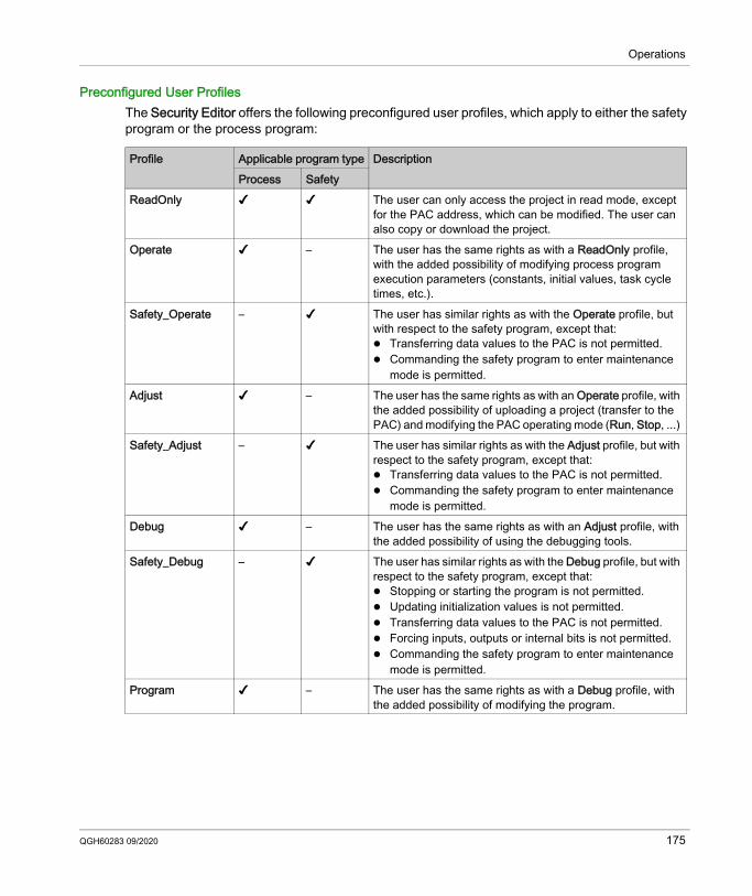
Operations
Preconfigured User ProfilesThe Security Editor offers the following preconfigured user profiles, which apply to either the safety program or the process program:
Profile Applicable program type DescriptionProcess Safety
ReadOnly ✔ ✔ The user can only access the project in read mode, except for the PAC address, which can be modified. The user can also copy or download the project.
Operate ✔ – The user has the same rights as with a ReadOnly profile, with the added possibility of modifying process program execution parameters (constants, initial values, task cycle times, etc.).
Safety_Operate – ✔ The user has similar rights as with the Operate profile, but with respect to the safety program, except that: Transferring data values to the PAC is not permitted. Commanding the safety program to enter maintenance
mode is permitted.Adjust ✔ – The user has the same rights as with an Operate profile, with
the added possibility of uploading a project (transfer to the PAC) and modifying the PAC operating mode (Run, Stop, ...)
Safety_Adjust – ✔ The user has similar rights as with the Adjust profile, but with respect to the safety program, except that: Transferring data values to the PAC is not permitted. Commanding the safety program to enter maintenance
mode is permitted.Debug ✔ – The user has the same rights as with an Adjust profile, with
the added possibility of using the debugging tools.Safety_Debug – ✔ The user has similar rights as with the Debug profile, but with
respect to the safety program, except that: Stopping or starting the program is not permitted. Updating initialization values is not permitted. Transferring data values to the PAC is not permitted. Forcing inputs, outputs or internal bits is not permitted. Commanding the safety program to enter maintenance
mode is permitted.Program ✔ – The user has the same rights as with a Debug profile, with
the added possibility of modifying the program.
QGH60283 09/2020 175
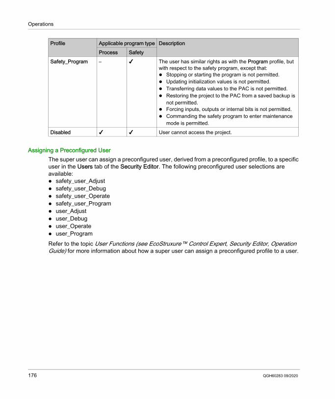
Operations
Assigning a Preconfigured UserThe super user can assign a preconfigured user, derived from a preconfigured profile, to a specific user in the Users tab of the Security Editor. The following preconfigured user selections are available: safety_user_Adjust safety_user_Debug safety_user_Operate safety_user_Program user_Adjust user_Debug user_Operate user_ProgramRefer to the topic User Functions (see EcoStruxure™ Control Expert, Security Editor, Operation Guide) for more information about how a super user can assign a preconfigured profile to a user.
Safety_Program – ✔ The user has similar rights as with the Program profile, but with respect to the safety program, except that: Stopping or starting the program is not permitted. Updating initialization values is not permitted. Transferring data values to the PAC is not permitted. Restoring the project to the PAC from a saved backup is
not permitted. Forcing inputs, outputs or internal bits is not permitted. Commanding the safety program to enter maintenance
mode is permitted.Disabled ✔ ✔ User cannot access the project.
Profile Applicable program type DescriptionProcess Safety
176 QGH60283 09/2020
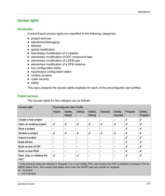
Operations
Access rights
IntroductionControl Expert access rights are classified in the following categories: project services adjustment/debugging libraries global modification elementary modification of a variable elementary modification of DDT compound data elementary modification of a DFB type elementary modification of a DFB instance bus configuration editor input/output configuration editor runtime screens cyber security safetyThis topic presents the access rights available for each of the preconfigured user profiles.
Project servicesThe access rights for this category are as follows:
Access right Preconfigured User ProfileAdjust Safety_
AdjustDebug Safety_
DebugOperate Safety_
OperateProgram Safety_
ProgramCreate a new project – – – – – – ✔ ✔Open an existing project ✔ ✔ ✔ ✔ ✔ ✔ ✔ ✔Save a project – – – – – – ✔ ✔SaveAs a project ✔ ✔ ✔ ✔ ✔ ✔ ✔ ✔Import a project – – – – – – ✔ ✔Build off-line – – – – – – ✔ ✔Build on-line STOP – – – – – – ✔ ✔Build on-line RUN – – – – – – ✔ ✔Start, stop or initialize the PAC*
✔ – ✔ – – – ✔ ✔
* Only process tasks are started or stopped. For a non-safety PAC, this means the PAC is started or stopped. For an M580 safety PAC, this means that tasks other than the SAFE task are started or stopped.✔ : Included– : not included
QGH60283 09/2020 177
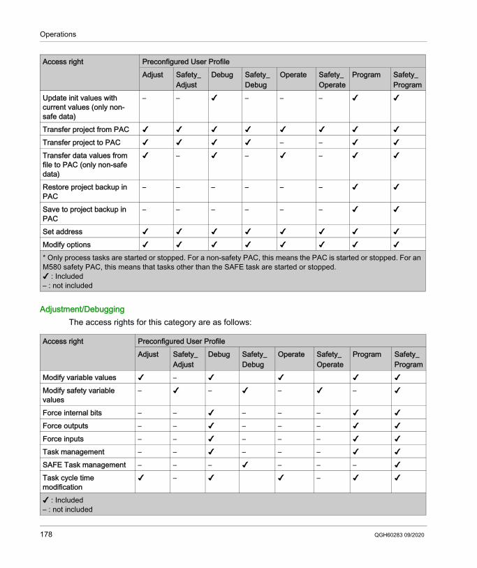
Operations
Adjustment/DebuggingThe access rights for this category are as follows:
Update init values with current values (only non-safe data)
– – ✔ – – – ✔ ✔
Transfer project from PAC ✔ ✔ ✔ ✔ ✔ ✔ ✔ ✔Transfer project to PAC ✔ ✔ ✔ ✔ – – ✔ ✔Transfer data values from file to PAC (only non-safe data)
✔ – ✔ – ✔ – ✔ ✔
Restore project backup in PAC
– – – – – – ✔ ✔
Save to project backup in PAC
– – – – – – ✔ ✔
Set address ✔ ✔ ✔ ✔ ✔ ✔ ✔ ✔Modify options ✔ ✔ ✔ ✔ ✔ ✔ ✔ ✔
Access right Preconfigured User ProfileAdjust Safety_
AdjustDebug Safety_
DebugOperate Safety_
OperateProgram Safety_
Program
* Only process tasks are started or stopped. For a non-safety PAC, this means the PAC is started or stopped. For an M580 safety PAC, this means that tasks other than the SAFE task are started or stopped.✔ : Included– : not included
Access right Preconfigured User ProfileAdjust Safety_
AdjustDebug Safety_
DebugOperate Safety_
OperateProgram Safety_
ProgramModify variable values ✔ – ✔ ✔ ✔ ✔Modify safety variable values
– ✔ – ✔ – ✔ – ✔
Force internal bits – – ✔ – – – ✔ ✔Force outputs – – ✔ – – – ✔ ✔Force inputs – – ✔ – – – ✔ ✔Task management – – ✔ – – – ✔ ✔SAFE Task management – – – ✔ – – – ✔Task cycle time modification
✔ – ✔ ✔ – ✔ ✔
✔ : Included– : not included
178 QGH60283 09/2020
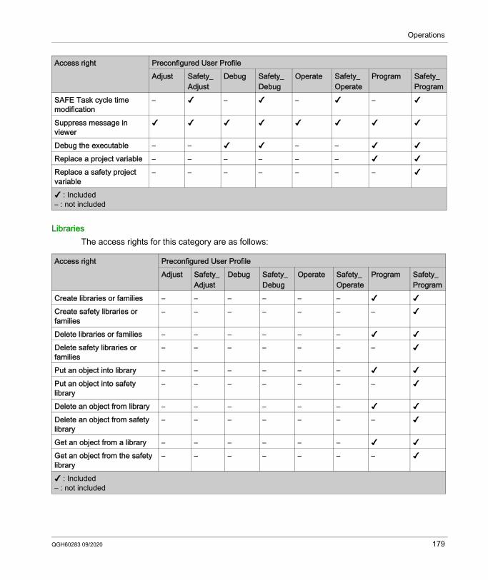
Operations
LibrariesThe access rights for this category are as follows:
SAFE Task cycle time modification
– ✔ – ✔ – ✔ – ✔
Suppress message in viewer
✔ ✔ ✔ ✔ ✔ ✔ ✔ ✔
Debug the executable – – ✔ ✔ – – ✔ ✔Replace a project variable – – – – – – ✔ ✔Replace a safety project variable
– – – – – – – ✔
Access right Preconfigured User ProfileAdjust Safety_
AdjustDebug Safety_
DebugOperate Safety_
OperateProgram Safety_
Program
✔ : Included– : not included
Access right Preconfigured User ProfileAdjust Safety_
AdjustDebug Safety_
DebugOperate Safety_
OperateProgram Safety_
ProgramCreate libraries or families – – – – – – ✔ ✔Create safety libraries or families
– – – – – – – ✔
Delete libraries or families – – – – – – ✔ ✔Delete safety libraries or families
– – – – – – – ✔
Put an object into library – – – – – – ✔ ✔Put an object into safety library
– – – – – – – ✔
Delete an object from library – – – – – – ✔ ✔Delete an object from safety library
– – – – – – – ✔
Get an object from a library – – – – – – ✔ ✔Get an object from the safety library
– – – – – – – ✔
✔ : Included– : not included
QGH60283 09/2020 179
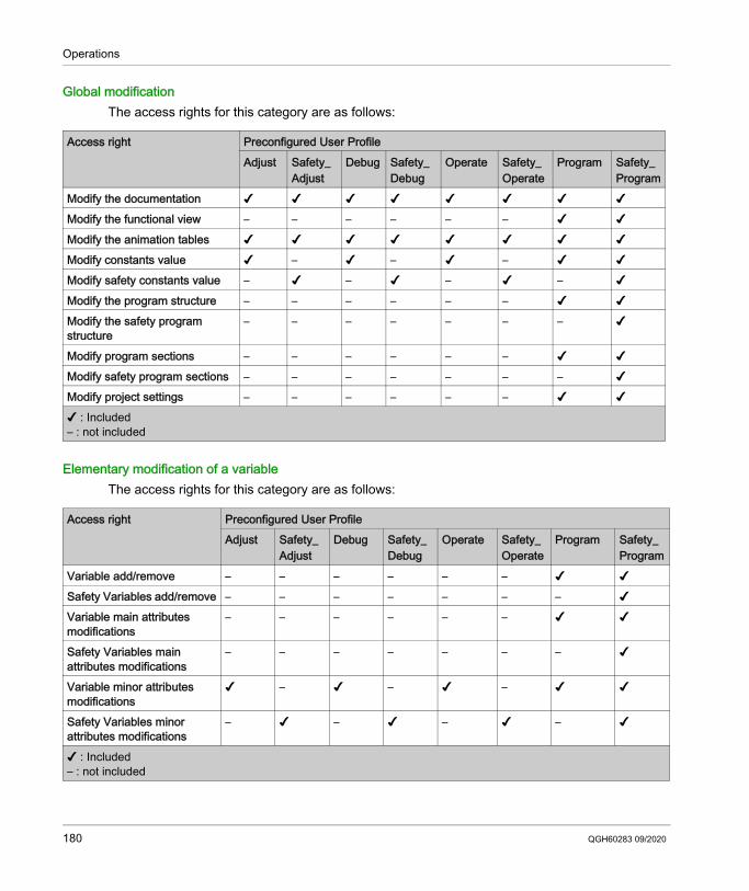
Operations
Global modificationThe access rights for this category are as follows:
Elementary modification of a variableThe access rights for this category are as follows:
Access right Preconfigured User ProfileAdjust Safety_
AdjustDebug Safety_
DebugOperate Safety_
OperateProgram Safety_
ProgramModify the documentation ✔ ✔ ✔ ✔ ✔ ✔ ✔ ✔Modify the functional view – – – – – – ✔ ✔Modify the animation tables ✔ ✔ ✔ ✔ ✔ ✔ ✔ ✔Modify constants value ✔ – ✔ – ✔ – ✔ ✔Modify safety constants value – ✔ – ✔ – ✔ – ✔Modify the program structure – – – – – – ✔ ✔Modify the safety program structure
– – – – – – – ✔
Modify program sections – – – – – – ✔ ✔Modify safety program sections – – – – – – – ✔Modify project settings – – – – – – ✔ ✔✔ : Included– : not included
Access right Preconfigured User ProfileAdjust Safety_
AdjustDebug Safety_
DebugOperate Safety_
OperateProgram Safety_
ProgramVariable add/remove – – – – – – ✔ ✔Safety Variables add/remove – – – – – – – ✔Variable main attributes modifications
– – – – – – ✔ ✔
Safety Variables main attributes modifications
– – – – – – – ✔
Variable minor attributes modifications
✔ – ✔ – ✔ – ✔ ✔
Safety Variables minor attributes modifications
– ✔ – ✔ – ✔ – ✔
✔ : Included– : not included
180 QGH60283 09/2020
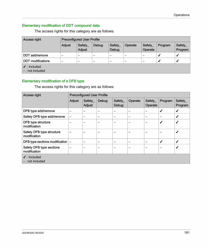
Operations
Elementary modification of DDT compound dataThe access rights for this category are as follows:
Elementary modification of a DFB typeThe access rights for this category are as follows:
Access right Preconfigured User ProfileAdjust Safety_
AdjustDebug Safety_
DebugOperate Safety_
OperateProgram Safety_
ProgramDDT add/remove – – – – – – ✔ ✔DDT modifications – – – – – – ✔ ✔✔ : Included– : not included
Access right Preconfigured User ProfileAdjust Safety_
AdjustDebug Safety_
DebugOperate Safety_
OperateProgram Safety_
ProgramDFB type add/remove – – – – – – ✔ ✔Safety DFB type add/remove – – – – – – – ✔DFB type structure modification
– – – – – – ✔ ✔
Safety DFB type structure modification
– – – – – – – ✔
DFB type sections modification – – – – – – ✔ ✔Safety DFB type sections modification
– – – – – – – ✔
✔ : Included– : not included
QGH60283 09/2020 181
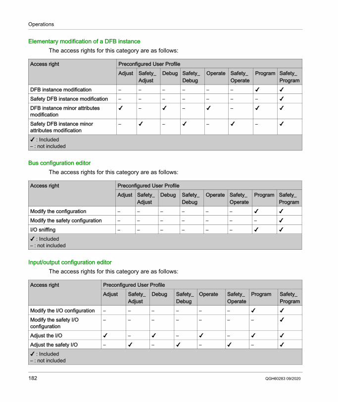
Operations
Elementary modification of a DFB instanceThe access rights for this category are as follows:
Bus configuration editorThe access rights for this category are as follows:
Input/output configuration editorThe access rights for this category are as follows:
Access right Preconfigured User ProfileAdjust Safety_
AdjustDebug Safety_
DebugOperate Safety_
OperateProgram Safety_
ProgramDFB instance modification – – – – – – ✔ ✔Safety DFB instance modification – – – – – – – ✔DFB instance minor attributes modification
✔ – ✔ – ✔ – ✔ ✔
Safety DFB instance minor attributes modification
– ✔ – ✔ – ✔ – ✔
✔ : Included– : not included
Access right Preconfigured User ProfileAdjust Safety_
AdjustDebug Safety_
DebugOperate Safety_
OperateProgram Safety_
ProgramModify the configuration – – – – – – ✔ ✔Modify the safety configuration – – – – – – – ✔I/O sniffing – – – – – – ✔ ✔✔ : Included– : not included
Access right Preconfigured User ProfileAdjust Safety_
AdjustDebug Safety_
DebugOperate Safety_
OperateProgram Safety_
ProgramModify the I/O configuration – – – – – – ✔ ✔Modify the safety I/O configuration
– – – – – – – ✔
Adjust the I/O ✔ – ✔ – ✔ – ✔ ✔Adjust the safety I/O – ✔ – ✔ – ✔ – ✔✔ : Included– : not included
182 QGH60283 09/2020
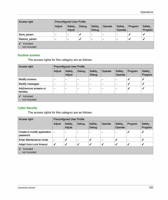
Operations
Runtime screensThe access rights for this category are as follows:
Cyber SecurityThe access rights for this category are as follows:
Save_param – – ✔ – – – ✔ ✔Restore_param – – ✔ – – – ✔ ✔
Access right Preconfigured User ProfileAdjust Safety_
AdjustDebug Safety_
DebugOperate Safety_
OperateProgram Safety_
Program
✔ : Included– : not included
Access right Preconfigured User ProfileAdjust Safety_
AdjustDebug Safety_
DebugOperate Safety_
OperateProgram Safety_
ProgramModify screens – – – – – – ✔ ✔Modify messages – – – – – – ✔ ✔Add/remove screens or families
– – – – – – ✔ ✔
✔ : Included– : not included
Access right Preconfigured User ProfileAdjust Safety_
AdjustDebug Safety_
DebugOperate Safety_
OperateProgram Safety_
ProgramCreate or modify application password
– – – – – – ✔ ✔
Enter Maintenance mode – ✔ – ✔ – ✔ – ✔Adapt Auto-Lock timeout ✔ ✔ ✔ ✔ ✔ ✔ ✔ ✔✔ : Included– : not included
QGH60283 09/2020 183
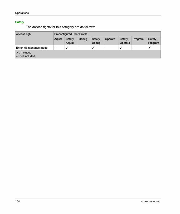
Operations
SafetyThe access rights for this category are as follows:
Access right Preconfigured User ProfileAdjust Safety_
AdjustDebug Safety_
DebugOperate Safety_
OperateProgram Safety_
ProgramEnter Maintenance mode – ✔ – ✔ – ✔ – ✔✔ : Included– : not included
184 QGH60283 09/2020
Operations
M580 Safety Project Settings
Section 8.10M580 Safety Project Settings
Project Settings for an M580 Safety Project in Control Expert
Scope-Specific Project SettingsSelect Tools → Project Settings... in the Control Expert main menu to open a window where you can configure and view the project settings for an M580 safety project. Project settings are divided into three groups, depending on the applicable Scope of the settings, as follows: common: These settings apply to the entire application, and can impact the global, process, and
safe areas of the project. process: These settings apply only to the process area of the project. safe: These settings apply only to the process area of the project.This topic describes only those parts of the Project Settings window that vary from an M580 non-safety project. Refer to the Project Settings section of the EcoStruxure™ Control Expert Operating Modes manual for information regarding features that are common to both M580 safety and non-safety projects.
QGH60283 09/2020 185
Operations
Common Project SettingsThe following Scope → common settings apply to the global, safe, and process project areas, but differently from the same settings in an M580 non-safety project:
Group Setting DescriptionGeneral settings:Build settings Free data memory (in kbytes) This setting is disabled.
NOTE: In an M580 safety system, the allocation of data is performed dynamically, and a fixed size data block does not need to be reserved.
Virtual connected mode This setting is disabled and de-selected.PLC embedded data
Data dictionary Usage of Process
Namespace
Determines how an operator screen can access and read process namespace variables: If selected, the operator screen can read process
area variables only by using the format “PROCESS.<variable name>”.
If de-selected, the operator screen can read process area variables only by using the format “<variable name>” without the PROCESS prefix.
NOTE: All variables in the safe area are accessed using the format “SAFE.<variable name>”.
Optimize data on-line change Applies to the: Process program in both safety and maintenance
operating modes. Safety program only in maintenance operating
mode.PLC diagnostics Rack Viewer diagnostics
information Rack Viewer variable names
Both of these settings are available to both process and safety variables.
Program Viewer information This setting is available for both process and safety code sections.
Time Time Stamping Mode This setting is available for both process and safety programs, with the exception that time stamping for safety variables is not supported.
Operator Screen settings:Controlled Screen Displaying screens controlled via
the PLCThis setting is available in the M580 safety PAC for the selected variable.
186 QGH60283 09/2020
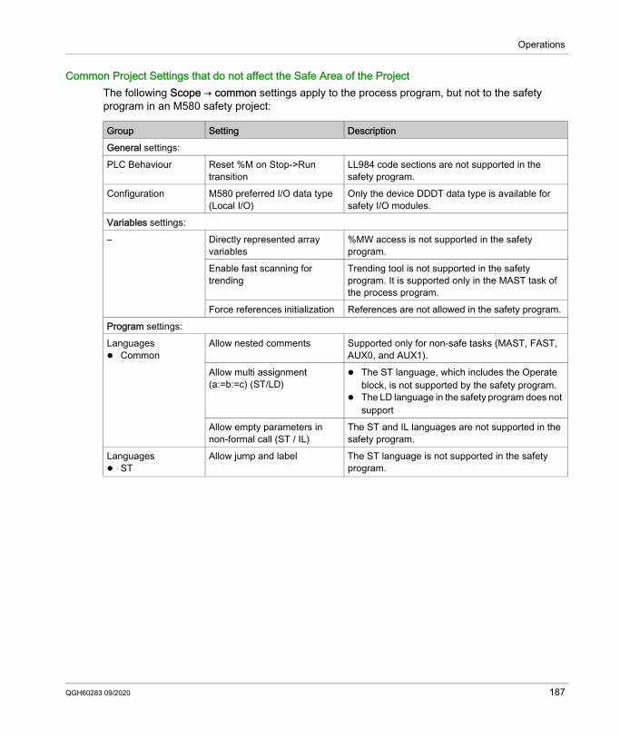
Operations
Common Project Settings that do not affect the Safe Area of the ProjectThe following Scope → common settings apply to the process program, but not to the safety program in an M580 safety project:
Group Setting DescriptionGeneral settings:PLC Behaviour Reset %M on Stop->Run
transitionLL984 code sections are not supported in the safety program.
Configuration M580 preferred I/O data type (Local I/O)
Only the device DDDT data type is available for safety I/O modules.
Variables settings:– Directly represented array
variables%MW access is not supported in the safety program.
Enable fast scanning for trending
Trending tool is not supported in the safety program. It is supported only in the MAST task of the process program.
Force references initialization References are not allowed in the safety program.Program settings:Languages Common
Allow nested comments Supported only for non-safe tasks (MAST, FAST, AUX0, and AUX1).
Allow multi assignment (a:=b:=c) (ST/LD)
The ST language, which includes the Operate block, is not supported by the safety program.
The LD language in the safety program does not support
Allow empty parameters in non-formal call (ST / IL)
The ST and IL languages are not supported in the safety program.
Languages ST
Allow jump and label The ST language is not supported in the safety program.
QGH60283 09/2020 187
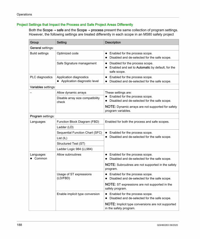
Operations
Project Settings that Impact the Process and Safe Project Areas DifferentlyBoth the Scope → safe and the Scope → process present the same collection of program settings. However, the following settings are treated differently in each scope in an M580 safety project
Group Setting DescriptionGeneral settings:Build settings Optimized code Enabled for the process scope.
Disabled and de-selected for the safe scope.
Safe Signature management Disabled for the process scope. Enabled and set to Automatic by default, for the
safe scope.PLC diagnostics Application diagnostics
Application diagnostic level Enabled for the process scope. Disabled and de-selected for the safe scope.
Variables settings:– Allow dynamic arrays These settings are:
Enabled for the process scope. Disabled and de-selected for the safe scope.
NOTE: Dynamic arrays are not supported for safety program variables.
Disable array size compatibility check
Program settings:Languages Function Block Diagram (FBD) Enabled for both the process and safe scopes.
Ladder (LD)Sequential Function Chart (SFC) Enabled for the process scope.
Disabled and de-selected for the safe scope.List (IL)Structured Test (ST)Ladder Logic 984 (LL984)
Languages Common
Allow subroutines Enabled for the process scope. Disabled and de-selected for the safe scope.
NOTE: Subroutines are not supported in the safety program.
Usage of ST expressions (LD/FBD)
Enabled for the process scope. Disabled and de-selected for the safe scope.
NOTE: ST expressions are not supported in the safety program.
Enable implicit type conversion Enabled for the process scope. Disabled and de-selected for the safe scope.
NOTE: Implicit type conversions are not supported in the safety program.
188 QGH60283 09/2020
Modicon M580
QGH60283 09/2020
Appendices
IntroductionThe appendices contain information on the IEC 61508 and its SIL policy. Further, technical data of the Safety and non-interfering modules are provided and example calculations are carried out.
What Is in This Appendix?The appendix contains the following chapters:
Chapter Chapter Name PageA IEC 61508 191B System Objects 199
QGH60283 09/2020 189

190 QGH60283 09/2020
Modicon M580
QGH60283 09/2020
IEC 61508
Appendix AIEC 61508
IntroductionThis chapter provides information on the Safety concepts of the IEC 61508 in general and its SIL policy in particular.
What Is in This Chapter?This chapter contains the following topics:
Topic PageGeneral Information on the IEC 61508 192SIL Policy 194
QGH60283 09/2020 191
General Information on the IEC 61508
IntroductionSafety-Related Systems are developed for use in processes in which risks to humans, environment, equipment and production are to be kept at an acceptable level. The risk depends on the severity and likelihood, thereby defining the necessary measures of protection.Concerning the Safety of processes, there are 2 sides to be considered: the regulations and requirements defined by official authorities in order to help protect humans,
environment, equipment, and production the measures by which these regulations and requirements are fulfilled
IEC 61508 DescriptionThe technical standard defining the requirements for Safety-Related Systems is the IEC 61508.It deals with the Functional Safety of electrical, electronic or programmable electronic Safety-Related Systems. A Safety-Related System is a system that is required to perform 1 or more specific functions to ensure risks are kept at an acceptable level. Such functions are defined as Safety Functions. A system is defined functionally Safe if random, systematic, and common cause failures do not lead to malfunctioning of the system and do not result in injury or death of humans, spills to the environment and loss of equipment and production.The standard defines a generic approach to all lifecycle activities for systems that are used to perform Safety Functions. It constitutes procedures to be used for the design, the development, and the validation of both hardware and software applied in Safety-Related Systems. Further, it determines rules concerning both the management of Functional Safety and documentation.
IEC 61511 DescriptionThe Functional Safety requirements defined in the IEC 61508 are refined specifically for the process industry sector in the following technical standard: the IEC 61511: Functional safety - safety instrumented systems for the process industry sectorThis standard guides the user in the application of a Safety-Related System, starting from the earliest phase of a project, continuing through the start up, covering modifications and eventual decommissioning activities. In summary, it deals with the Safety Lifecycle of all components of a Safety-Related System used in the process industry.
192 QGH60283 09/2020
Risk DescriptionThe IEC 61508 is based on the concepts of risk analysis and Safety Function. The risk depends on severity and probability. It can be reduced to a tolerable level by applying a Safety Function that consists of an electrical, electronic or programmable electronic system. Further, it should be reduced to a level that is as low as reasonably practicable. In summary, the IEC 61508 views risks as follows: Zero risk can never be reached. Safety is to be considered from the beginning. Intolerable risks are to be reduced.
QGH60283 09/2020 193
SIL Policy
IntroductionThe SIL value evaluates the robustness of an application against failures, thus indicating the ability of a system to perform a Safety Function within a defined probability. The IEC 61508 specifies 4 levels of Safety performance depending on the risk or impacts caused by the process for which the Safety-Related System is used. The more dangerous the possible impacts are on community and environment, the higher the Safety requirements are to lower the risk.
SIL Value DescriptionDiscrete level (1 out of a possible 4) for specifying the Safety Integrity requirements of the Safety Functions to be allocated to the Safety-Related Systems, where Safety Integrity Level 4 has the highest level of Safety Integrity and Safety Integrity Level 1 has the lowest, see SILs for Low Demand, page 195.
SIL Requirements DescriptionTo achieve Functional Safety, 2 types of requirements are necessary: Safety Function requirements, defining what Safety Functions have to be performed Safety Integrity requirements, defining what degree of certainty is necessary that the Safety
Functions are performedThe Safety Function requirements are derived from hazard analysis and the Safety Integrity ones from risk assessment.They consist of the following quantities: Mean time between failures Probabilities of failure Failure rates Diagnostic coverage Safe failure fraction Hardware fault toleranceDepending on the level of Safety Integrity, these quantities must range between defined limits.NOTE: Mixing different safety integrity level devices on a network or safety function requires a high degree of care with respect to the requirements of IEC 61508, and produces design and operational implications.
194 QGH60283 09/2020
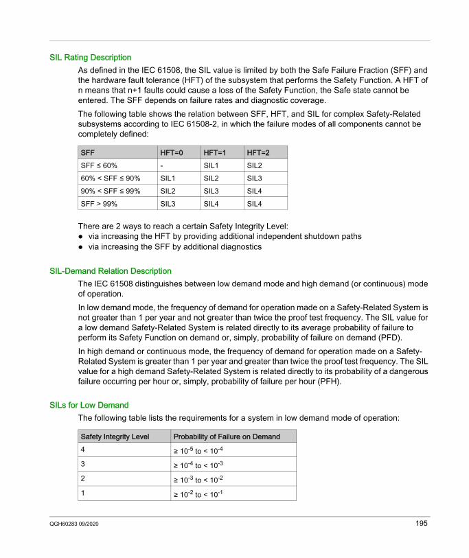
SIL Rating DescriptionAs defined in the IEC 61508, the SIL value is limited by both the Safe Failure Fraction (SFF) and the hardware fault tolerance (HFT) of the subsystem that performs the Safety Function. A HFT of n means that n+1 faults could cause a loss of the Safety Function, the Safe state cannot be entered. The SFF depends on failure rates and diagnostic coverage.The following table shows the relation between SFF, HFT, and SIL for complex Safety-Related subsystems according to IEC 61508-2, in which the failure modes of all components cannot be completely defined:
There are 2 ways to reach a certain Safety Integrity Level: via increasing the HFT by providing additional independent shutdown paths via increasing the SFF by additional diagnostics
SIL-Demand Relation DescriptionThe IEC 61508 distinguishes between low demand mode and high demand (or continuous) mode of operation.In low demand mode, the frequency of demand for operation made on a Safety-Related System is not greater than 1 per year and not greater than twice the proof test frequency. The SIL value for a low demand Safety-Related System is related directly to its average probability of failure to perform its Safety Function on demand or, simply, probability of failure on demand (PFD).In high demand or continuous mode, the frequency of demand for operation made on a Safety-Related System is greater than 1 per year and greater than twice the proof test frequency. The SIL value for a high demand Safety-Related System is related directly to its probability of a dangerous failure occurring per hour or, simply, probability of failure per hour (PFH).
SILs for Low DemandThe following table lists the requirements for a system in low demand mode of operation:
SFF HFT=0 HFT=1 HFT=2SFF ≤ 60% - SIL1 SIL260% < SFF ≤ 90% SIL1 SIL2 SIL390% < SFF ≤ 99% SIL2 SIL3 SIL4SFF > 99% SIL3 SIL4 SIL4
Safety Integrity Level Probability of Failure on Demand4 ≥ 10-5 to < 10-4
3 ≥ 10-4 to < 10-3
2 ≥ 10-3 to < 10-2
1 ≥ 10-2 to < 10-1
QGH60283 09/2020 195
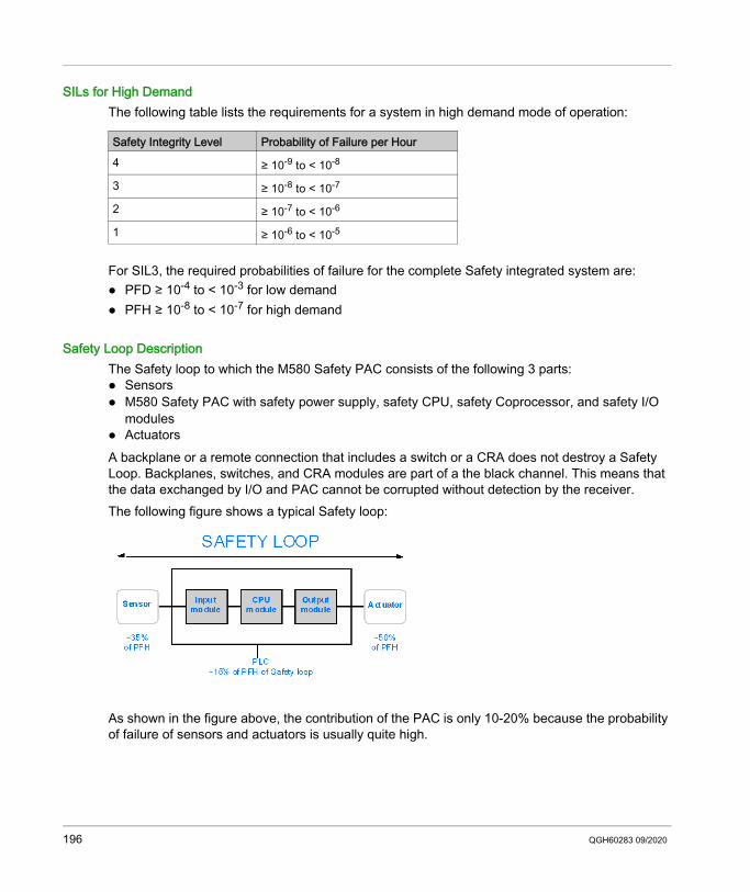
SILs for High DemandThe following table lists the requirements for a system in high demand mode of operation:
For SIL3, the required probabilities of failure for the complete Safety integrated system are: PFD ≥ 10-4 to < 10-3 for low demand PFH ≥ 10-8 to < 10-7 for high demand
Safety Loop DescriptionThe Safety loop to which the M580 Safety PAC consists of the following 3 parts: Sensors M580 Safety PAC with safety power supply, safety CPU, safety Coprocessor, and safety I/O
modules ActuatorsA backplane or a remote connection that includes a switch or a CRA does not destroy a Safety Loop. Backplanes, switches, and CRA modules are part of a the black channel. This means that the data exchanged by I/O and PAC cannot be corrupted without detection by the receiver.The following figure shows a typical Safety loop:
As shown in the figure above, the contribution of the PAC is only 10-20% because the probability of failure of sensors and actuators is usually quite high.
Safety Integrity Level Probability of Failure per Hour4 ≥ 10-9 to < 10-8
3 ≥ 10-8 to < 10-7
2 ≥ 10-7 to < 10-6
1 ≥ 10-6 to < 10-5
196 QGH60283 09/2020
A conservative assumption of 10% for the Safety PAC’s contribution to the overall probability leaves more margin for the user and results in the following required probabilities of failure for the Safety PAC: PFD ≥ 10-5 to < 10-4 for low demand PFH ≥ 10-9 to < 10-8 for high demand
PFD Equation DescriptionThe IEC 61508 assumes that half of the failures end in a Safe state. Therefore, the failure rate λ is divided into λS - the safe failure and λD - the dangerous failure, itself composed of λDD - dangerous failure detected by the internal diagnostic λDU - dangerous failure undetected.
The failure rate can be calculated by using the mean time between failures (MTBF), a module specific value, as follows:λ = 1/MTBFThe equation for calculating the probability of failure on demand is:PFD(t) = λDU x t
t represents the time between 2 proof tests.The probability of failure per hour implies a time interval of 1 hour. Therefore, the PFD equation is reduced to the following one:PFH = λDU
QGH60283 09/2020 197

198 QGH60283 09/2020
Modicon M580System ObjectsQGH60283 09/2020
System Objects
Appendix BSystem Objects
IntroductionThis chapter describes the system bits and words of the M580 Safety PAC.NOTE: The symbols associated with each bit object or system word mentioned in the descriptive tables of these objects are not implemented as standard in the software, but can be entered using the data editor.
What Is in This Chapter?This chapter contains the following topics:
Topic PageM580 Safety System Bits 200M580 Safety System Words 202
QGH60283 09/2020 199
System Objects
M580 Safety System Bits
System Bits for SAFE Task ExecutionThe following system bits apply to the M580 safety PAC. For a description of system bits that apply to both the M580 safety PAC and non-safety M580 PACs, refer to the presentation of System Bits in the EcoStruxure™ Control Expert System Bits and Words Reference Manual.These system bits are related to the execution SAFE task, but are not directly accessible in safety program code. They can be accessed only via the S_SYST_READ_TASK_BIT_MX and S_SYST_RESET_TASK_BIT_MX blocks.
BitSymbol
Function Description Initial State
Type
%S17CARRY
Rotate shift output
During a rotate shift operation in the SAFE task, this bit takes the state of the outgoing bit.
0 R/W
%S18OVERFLOW
Overflow or arithmetic error detected
Normally set to 0, this bit is set to 1 in the event of a capacity overflow if there is: A result greater than + 32 767 or less than - 32 768,
in single length. A result greater than + 65 535, in unsigned integer. A result greater than + 2 147 483 647 or less than -
2 147 483 648, in double length A result greater than +4 294 967 296, in double
length or unsigned integer. Division by 0. The root of a negative number. Forcing to a non-existent step on a drum. Stacking up of an already full register, emptying of
an already empty register.
0 R/W
%S211RSTTASKRUN
First SAFE task scan in RUN
Tested in the SAFE task, this bit indicates the first cycle of this task. It is set to 1 at the start of the cycle and reset to 0 at the end of the cycle.
NOTE: The first cycle of the task status can be read using
the SCOLD output of the S_SYST_STAT_MX system function block.
This bit is not effective for M580 Safety Hot Standby systems.
0 R/W
200 QGH60283 09/2020
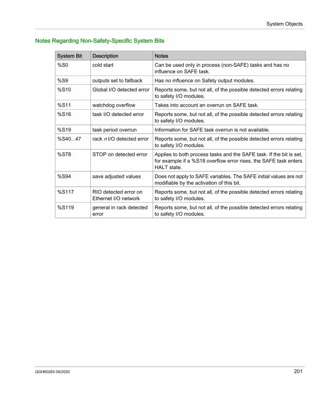
System Objects
Notes Regarding Non-Safety-Specific System Bits
System Bit Description Notes%S0 cold start Can be used only in process (non-SAFE) tasks and has no
influence on SAFE task.%S9 outputs set to fallback Has no influence on Safety output modules.%S10 Global I/O detected error Reports some, but not all, of the possible detected errors relating
to safety I/O modules.%S11 watchdog overflow Takes into account an overrun on SAFE task.%S16 task I/O detected error Reports some, but not all, of the possible detected errors relating
to safety I/O modules.%S19 task period overrun Information for SAFE task overrun is not available.%S40...47 rack n I/O detected error Reports some, but not all, of the possible detected errors relating
to safety I/O modules.%S78 STOP on detected error Applies to both process tasks and the SAFE task. If the bit is set,
for example if a %S18 overflow error rises, the SAFE task enters HALT state.
%S94 save adjusted values Does not apply to SAFE variables. The SAFE initial values are not modifiable by the activation of this bit.
%S117 RIO detected error on Ethernet I/O network
Reports some, but not all, of the possible detected errors relating to safety I/O modules.
%S119 general in rack detected error
Reports some, but not all, of the possible detected errors relating to safety I/O modules.
QGH60283 09/2020 201
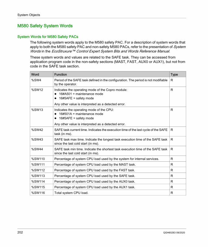
System Objects
M580 Safety System Words
System Words for M580 Safety PACsThe following system words apply to the M580 safety PAC. For a description of system words that apply to both the M580 safety PAC and non-safety M580 PACs, refer to the presentation of System Words in the EcoStruxure™ Control Expert System Bits and Words Reference Manual.These system words and values are related to the SAFE task. They can be accessed from application program code in the non-safety sections (MAST, FAST, AUX0 or AUX1), but not from code in the SAFE task section.
Word Function Type%SW4 Period of the SAFE task defined in the configuration. The period is not modifiable
by the operator.R
%SW12 Indicates the operating mode of the Copro module: 16#A501 = maintenance mode 16#5AFE = safety mode
Any other value is interpreted as a detected error.
R
%SW13 Indicates the operating mode of the CPU: 16#501A = maintenance mode 16#5AFE = safety mode
Any other value is interpreted as a detected error.
R
%SW42 SAFE task current time. Indicates the execution time of the last cycle of the SAFE task (in ms).
R
%SW43 SAFE task max time. Indicate the longest task execution time of the SAFE task since the last cold start (in ms).
R
%SW44 SAFE task min time. Indicate the shortest task execution time of the SAFE task since the last cold start (in ms).
R
%SW110 Percentage of system CPU load used by the system for internal services. R%SW111 Percentage of system CPU load used by the MAST task. R%SW112 Percentage of system CPU load used by the FAST task. R%SW113 Percentage of system CPU load used by the SAFE task. R%SW114 Percentage of system CPU load used by the AUX0 task. R%SW115 Percentage of system CPU load used by the AUX1 task. R%SW116 Total system CPU load. R
202 QGH60283 09/2020
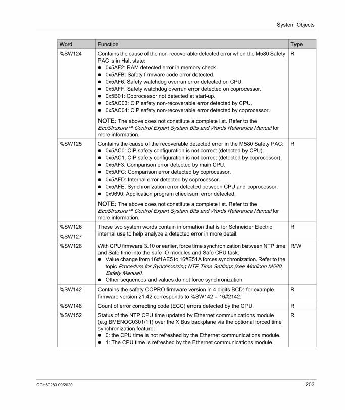
System Objects
%SW124 Contains the cause of the non-recoverable detected error when the M580 Safety PAC is in Halt state: 0x5AF2: RAM detected error in memory check. 0x5AFB: Safety firmware code error detected. 0x5AF6: Safety watchdog overrun error detected on CPU. 0x5AFF: Safety watchdog overrun error detected on coprocessor. 0x5B01: Coprocessor not detected at start-up. 0x5AC03: CIP safety non-recoverable error detected by CPU. 0x5AC04: CIP safety non-recoverable error detected by coprocessor.
NOTE: The above does not constitute a complete list. Refer to the EcoStruxure™ Control Expert System Bits and Words Reference Manual for more information.
R
%SW125 Contains the cause of the recoverable detected error in the M580 Safety PAC: 0x5AC0: CIP safety configuration is not correct (detected by CPU). 0x5AC1: CIP safety configuration is not correct (detected by coprocessor). 0x5AF3: Comparison error detected by main CPU. 0x5AFC: Comparison error detected by coprocessor. 0x5AFD: Internal error detected by coprocessor. 0x5AFE: Synchronization error detected between CPU and coprocessor. 0x9690: Application program checksum error detected.
NOTE: The above does not constitute a complete list. Refer to the EcoStruxure™ Control Expert System Bits and Words Reference Manual for more information.
R
%SW126 These two system words contain information that is for Schneider Electric internal use to help analyze a detected error in more detail.
R%SW127%SW128 With CPU firmware 3.10 or earlier, force time synchronization between NTP time
and Safe time into the safe IO modules and Safe CPU task: Value change from 16#1AE5 to 16#E51A forces synchronization. Refer to the
topic Procedure for Synchronizing NTP Time Settings (see Modicon M580, Safety Manual).
Other sequences and values do not force synchronization.
R/W
%SW142 Contains the safety COPRO firmware version in 4 digits BCD: for example firmware version 21.42 corresponds to %SW142 = 16#2142.
R
%SW148 Count of error correcting code (ECC) errors detected by the CPU. R%SW152 Status of the NTP CPU time updated by Ethernet communications module
(e.g BMENOC0301/11) over the X Bus backplane via the optional forced time synchronization feature: 0: the CPU time is not refreshed by the Ethernet communications module. 1: The CPU time is refreshed by the Ethernet communications module.
R
Word Function Type
QGH60283 09/2020 203
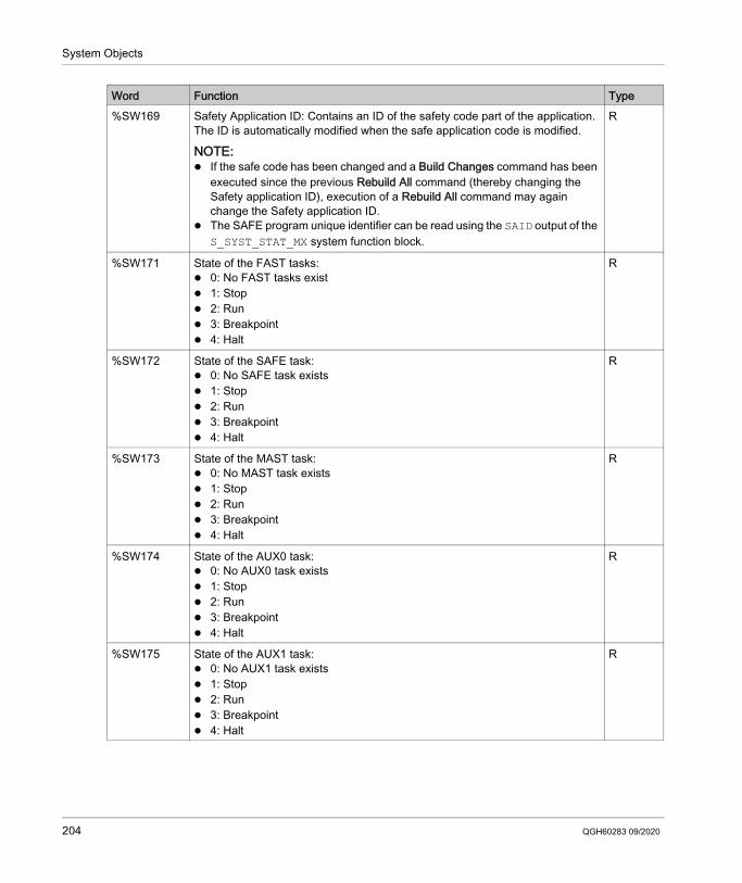
System Objects
%SW169 Safety Application ID: Contains an ID of the safety code part of the application. The ID is automatically modified when the safe application code is modified.
NOTE: If the safe code has been changed and a Build Changes command has been
executed since the previous Rebuild All command (thereby changing the Safety application ID), execution of a Rebuild All command may again change the Safety application ID.
The SAFE program unique identifier can be read using the SAID output of the S_SYST_STAT_MX system function block.
R
%SW171 State of the FAST tasks: 0: No FAST tasks exist 1: Stop 2: Run 3: Breakpoint 4: Halt
R
%SW172 State of the SAFE task: 0: No SAFE task exists 1: Stop 2: Run 3: Breakpoint 4: Halt
R
%SW173 State of the MAST task: 0: No MAST task exists 1: Stop 2: Run 3: Breakpoint 4: Halt
R
%SW174 State of the AUX0 task: 0: No AUX0 task exists 1: Stop 2: Run 3: Breakpoint 4: Halt
R
%SW175 State of the AUX1 task: 0: No AUX1 task exists 1: Stop 2: Run 3: Breakpoint 4: Halt
R
Word Function Type
204 QGH60283 09/2020
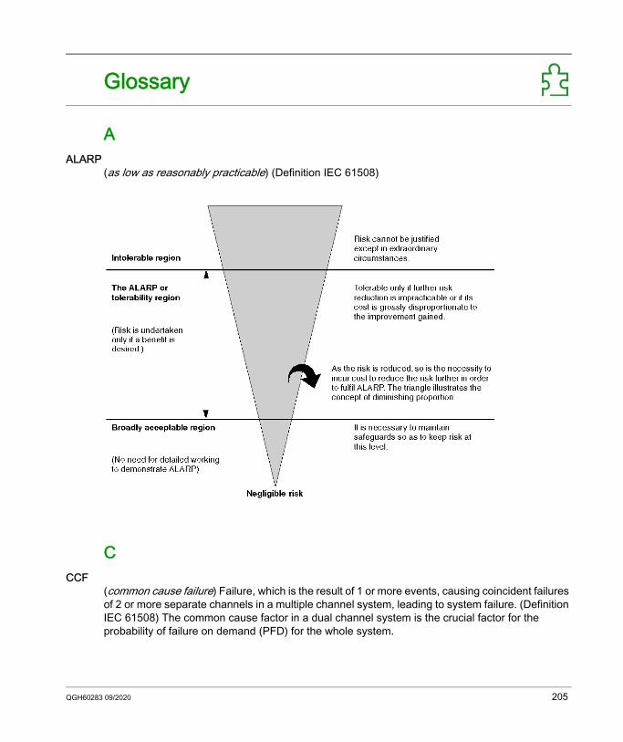
Modicon M580GlossaryQGH60283 09/2020
Glossary
AALARP
(as low as reasonably practicable) (Definition IEC 61508)
CCCF
(common cause failure) Failure, which is the result of 1 or more events, causing coincident failures of 2 or more separate channels in a multiple channel system, leading to system failure. (Definition IEC 61508) The common cause factor in a dual channel system is the crucial factor for the probability of failure on demand (PFD) for the whole system.
QGH60283 09/2020 205
Glossary
DDIO
(distributed I/O) Also known as distributed equipment. DRSs use DIO ports to connect distributed equipment.
FFTP
(file transfer protocol) A protocol that copies a file from one host to another over a TCP/IP-based network, such as the internet. FTP uses a client-server architecture as well as separate control and data connections between the client and server.
HHFT
(hardware fault tolerance) (Definition IEC 61508)A hardware fault tolerance of N means that N + 1 faults could cause a loss of the Safety Function, for instance: HFT = 0: The 1st failure could cause a loss of the Safety Function HFT = 1: 2 faults in combination could cause a loss of the Safety Function. (There are 2 different
paths to go to a Safe state. Loss of the Safety Function means that a Safe state cannot be entered.
SSFF
(safe failure fraction)
206 QGH60283 09/2020
Modicon M580IndexQGH60283 09/2020
Index
0-961508
IEC, 19261511
IEC, 192
Aalarm relay terminal block, 62animation tables, 140application
password, 156
BBME•58•040S CPU
performance characteristics, 48BMEP58CRPOS3 coprocessor
performance characteristics, 48BMXRMS004GPF, 46BMXSAI0410
performance characteristics, 71BMXSDI1602
performance characteristics, 73BMXSDO0802
performance characteristics, 75BMXSRA0405
performance characteristics, 77BMXXCAUSB018 USB cables, 43BMXXCAUSB045 USB cables, 43build command
Build Changes, 128Rebuild All Project, 128Renew Ids & Rebuild All, 128
QGH60283 09/2020
Ccold start, 122Control Expert
data separation, 106managing access to, 174predefined user profiles, 177project settings, 185security editor, 177
coprocessordimensions, 33front panel, 34
coprocessor LEDs, 38CPU
dimensions, 33front panel, 33install, 90
CPU LEDs, 38
Ddata initializing command
Init, 139Init Safety, 139
data separation in Control Expert, 106data storage
protecting, 167dimension
coprocessor, 33CPU, 33M580 safety power supply, 52
dimensionssafety I/O module, 64
dual network ports, 42
207
Index
EEthernet ports, 40
dual network ports, 42LEDs, 41pins, 40service port, 42
Ffailure rate, 197firmware
protecting, 165update, 102upgrade, 102, 103
front panelcoprocessor, 34CPU, 33power supply, 52safety I/O module, 65
FTPSD memory card, 46
Hhardware fault tolerance (HFT), 195HFT (hardware fault tolerance), 195HMI, 143
II/O configuration
locking, 136I/O module
install, 97IEC 61508
Functional Safety, 192IEC 61511
Functional Safety for the process indus-try, 192
initializing data, 139
208
installCPU, 90I/O module, 97local rack, 81memory card, 99power supply, 93
LLED panel
power supply, 53LEDs
coprocessor, 38CPU, 38safety I/O module, 68
local rackinstall, 81
locking I/O configuration, 136
MM580 safety power supply
dimensions, 52front panel, 52LED panel, 53RESET function, 53
maintenance input, 113maintenance operating mode, 111maximum devices
CIP Safety topology, 24mean time between failures (MTBF), 197memory card
FTP, 46install, 99
modulescertified, 16non-interfering, 17non-interfering type 1, 17non-interfering type 2, 20
MTBF (mean time between failures), 197
Ooperating mode, 110operating states, 115
QGH60283 09/2020
Index
Ppassword
application, 156lost or forgotten, 169reset, 169section, 160, 163
performance characteristicsBMXSAI0410, 71BMXSDI1602, 73BMXSDO0802, 75BMXSRA0405, 77CPU & coprocessor, 48power supply, 57
PFD (probability of failure on demand), 195PFH (probability of failure per hour), 195power supply
install, 93performance characteristics, 57
probability of failure on demand (PFD), 195probability of failure per hour (PFH), 195process namespace
usage by operator screen, 186usage of, 185
project settings, 185protecting
data storage, 167firmware, 165
Rrack
mounting, 86rack extender module, 88redundant link port, 45RESET, 53
Ssafe area
password, 160safe failure fraction (SFF), 195safe signature, 129SAFE task
configuring, 145
QGH60283 09/2020
safety I/O moduledimensions, 64front panel, 65LEDs, 68
Safety Integrity Level (SIL), 194Safety loop, 196safety operating mode, 110safety system bits, 200safety system words, 202SD memory card
FTP, 46section
password, 163security editor, 174service port, 42SFF (safe failure fraction), 195SFP socket, 45SIL (Safety Integrity Level, 194SourceSafeSignature, 129start up, 120
after power interruption, 120cold start, 122initial, 120warm start, 122
systembits, 200words, 202
Ttasks, 124, 145
configuring, 125topology
designing, 22distributed equipment, 29high availability, 26local main rack plus extension, 25peer-to-peer, 28
trending tool, 143
Uupdate
firmware, 102
209
Index
upgradefirmware, 102, 103
usage of process namespace, 185, 186USB
cables, 43pin assignments, 43transparency, 43
Wwarm start, 122
210
QGH60283 09/2020