Embed Size (px)
Citation preview
Datasheet
Fon: +49 7143/96669-00 Index: 05/2017 [email protected] www.nieruf.com
Safety valve TYPE SV01 / SV02
Description:
Safety valves are used to protect a closed system, pressure tanks etc. against overpressure.
Features:
- for air and other neutral, non-poisonous and non-flammable gases which can be freely discharged into the environment
- with lifting mechanism - TUV-type test approval letter D/G - EC type examination Letter S/G- Safety valves are set and sealed at the
factory
Connection: Temperature: Set pressure: 1/4“, 3/8“, 1/2“, 3/4“, 1“, 1 1/4“, 1 1/2“, 2“
-60°C to +225°C – depending on design
0,2 bar – 50,0 bar– depending on design
Materials: Component Type SV01 Type SV02 Body brass CW617N Stainless steel 1.4404 Internal parts brass CW617N Stainless steel 1.4404 Spring Stainless steel Stainless steel seal: FKM Fluorocarbon -20°C to +200°C = 25 bar set pressure PTFE Polytetrafluoroethylene -60°C to +225°C + 25 bar set pressure
Approvals: AD 2000 sheet A2 DIN EN ISO 4126-1 PED 2014/68/EU
Datasheet
Fon: +49 7143/96669-00 Index: 05/2017 [email protected] www.nieruf.com
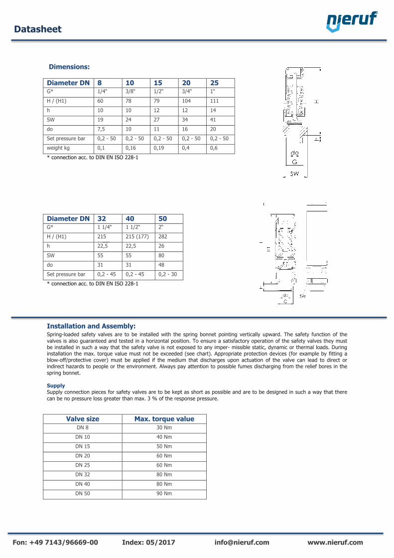
Dimensions:
Diameter DN 8 10 15 20 25 G* 1/4“ 3/8“ 1/2“ 3/4“ 1“
H / (H1) 60 78 79 104 111 h 10 10 12 12 14 SW 19 24 27 34 41 do 7,5 10 11 16 20 Set pressure bar 0,2 - 50 0,2 - 50 0,2 - 50 0,2 - 50 0,2 - 50 weight kg 0,1 0,16 0,19 0,4 0,6
* connection acc. to DIN EN ISO 228-1
Diameter DN 32 40 50 G* 1 1/4“ 1 1/2“ 2“ H / (H1) 215
(177) 215 (177) 282
h 22,5 22,5 26
SW 55 55 80 do 31 31 48 Set pressure bar 0,2 - 45 0,2 - 45 0,2 - 30 * connection acc. to DIN EN ISO 228-1
Installation and Assembly: Spring-loaded safety valves are to be installed with the spring bonnet pointing vertically upward. The safety function of the valves is also guaranteed and tested in a horizontal position. To ensure a satisfactory operation of the safety valves they must be installed in such a way that the safety valve is not exposed to any imper- missible static, dynamic or thermal loads. During installation the max. torque value must not be exceeded (see chart). Appropriate protection devices (for example by fitting a blow-off/protective cover) must be applied if the medium that discharges upon actuation of the valve can lead to direct or indirect hazards to people or the environment. Always pay attention to possible fumes discharging from the relief bores in the spring bonnet. Supply Supply connection pieces for safety valves are to be kept as short as possible and are to be designed in such a way that there can be no pressure loss greater than max. 3 % of the response pressure.
Valve size Max. torque value DN 8 30 Nm DN 10 40 Nm DN 15 50 Nm
m DN 20 60 Nm DN 25 60 Nm DN 32 80 Nm
DN 40 80 Nm DN 50 90 Nm
www.goetze-armaturen.de | [email protected] | Telefon: +49(0)7141.48894-60
NENNWEITEN, ANSCHLÜSSE, EINBAUMASSE
Baureihe 810 : Anschluss, Einbaumaße, Einstellbereiche
Nennweite
Anschluss DIN EN ISO 228
Einbaumaße in mm
Gewicht
Einstellbereich
DN 8 10 15 20 25
G 1/4" (8) 3/8" (10) 1/2" (15) 3/4" (20) 1" (25)
H 60 65 78 66 79 94 104 111
h 10 10 10 12 12 12 12 14
SW 19 24 24 27 27 34 34 41
do 7,5 10 10 11 11 16 16 20
kg 0,1 0,14 0,16 0,17 0,19 0,35 0,4 0,6
bar 0,2-50 0,2-9 9,1-50 0,2-9 9,1-50 0,2-9 9,1-50 0,2-50
HAUPTABMESSUNGEN, EINBAUMASSE
EIGENE AUSWAHL / VENTILKONFIGURATION
Bau-reihe
Ventil-ausführung
Medium Anlüftung Nennweite DN
Anschlussart Anschlussgröße Dichtung Optionen Einstell-druck
Stück-zahl
Eintritt Austritt Eintritt Austritt
810 s G K 10 m – 10 – FKM 11,5 50
810 s G K – –
810 s G K – –
810 s G K – –
In dieser Tabelle haben Sie die Möglichkeit, ein Ventil nach Ihren individuellen Anforderungen zu konfi gurieren (ähnlich dem aufgeführten Beispiel, welches Sie vor Ihrem Eintrag bitte streichen sollten). Füllen Sie die Felder einfach handschriftlich aus, indem Sie die gewünschten Abkürzungen aus diesem Datenblatt verwenden. Danach faxen Sie diese Seite an: +49(0)7141.4889488Bitte vergessen Sie Ihre persönlichen Angaben nicht, damit unser Service-Team Sie kontaktieren kann.
Name
Vorname
Firma
Telefon
www.goetze-armaturen.de | [email protected] | Telefon: +49(0)7141.48894-60
NENNWEITEN, ANSCHLÜSSE, EINBAUMASSE
Baureihe 412 : Anschluss, Einbaumaße, Einstellbereiche
Nennweite
Anschluss DIN EN ISO 228
Einbaumaße in mm
Gewicht
Einstellbereich
Einstellbereich ASME ¹Typ 412 mit der Option SHORT im Druckbereich 0,2 bis 6 bar auch in kurzer Ausführung
DN 15 20 25 32 40 50
G 1/2" (15) 3/4" (20) 1" (25) 1 1/4" (32) 1 1/2" (40) 2" (50)
H (H1) 144 177 177 215 (1771) 215 (1771) 282
h 12 15 15 22,5 22,5 26
SW 32 41 41 55 55 80
do 14 20 24 32 32 48
kg 0,6 1,3 1,3 2,6 2,6 5,4
bar 0,2-50 0,2-50 0,2-50 0,2-50 0,2-50 0,2-30
psi 14,5-725 14,5-725 14,5-725 14,5-725 14,5-725 -
HAUPTABMESSUNGEN, EINBAUMASSE
EIGENE AUSWAHL / VENTILKONFIGURATION
Bau-reihe
Ventil-ausführung
Medium Anlüftung Nennweite DN
Anschlussart Anschlussgröße Dichtung Optionen Einstell-druck
Stück-zahl
Eintritt Austritt Eintritt Austritt
412 s G K 20 NPT-m – 20 – FKM 4,5 2
412 s G K 40 NPT-m – 40 – PTFE SHORT 5,0 5
412 s G K – –
412 s G K – –
In dieser Tabelle haben Sie die Möglichkeit, ein Ventil nach
Ihren individuellen Anforderungen zu konfi gurieren (ähnlich
dem aufgeführten Beispiel, welches Sie vor Ihrem Eintrag bitte
streichen sollten). Füllen Sie die Felder einfach handschriftlich
aus, indem Sie die gewünschten Abkürzungen aus diesem
Datenblatt verwenden.
Danach faxen Sie diese Seite an: +49(0)7141.4889488
Bitte vergessen Sie Ihre persönlichen Angaben nicht, damit
unser Service-Team Sie kontaktieren kann.
Name
Vorname
Firma
Telefon
Kapitel4 _DE-Freigegeben.indd 1 5 1 7 .0 1 .2 0 1 4 0 8 :5 1 :4 5
Datasheet
Fon: +49 7143/96669-00 Index: 05/2017 [email protected] www.nieruf.com
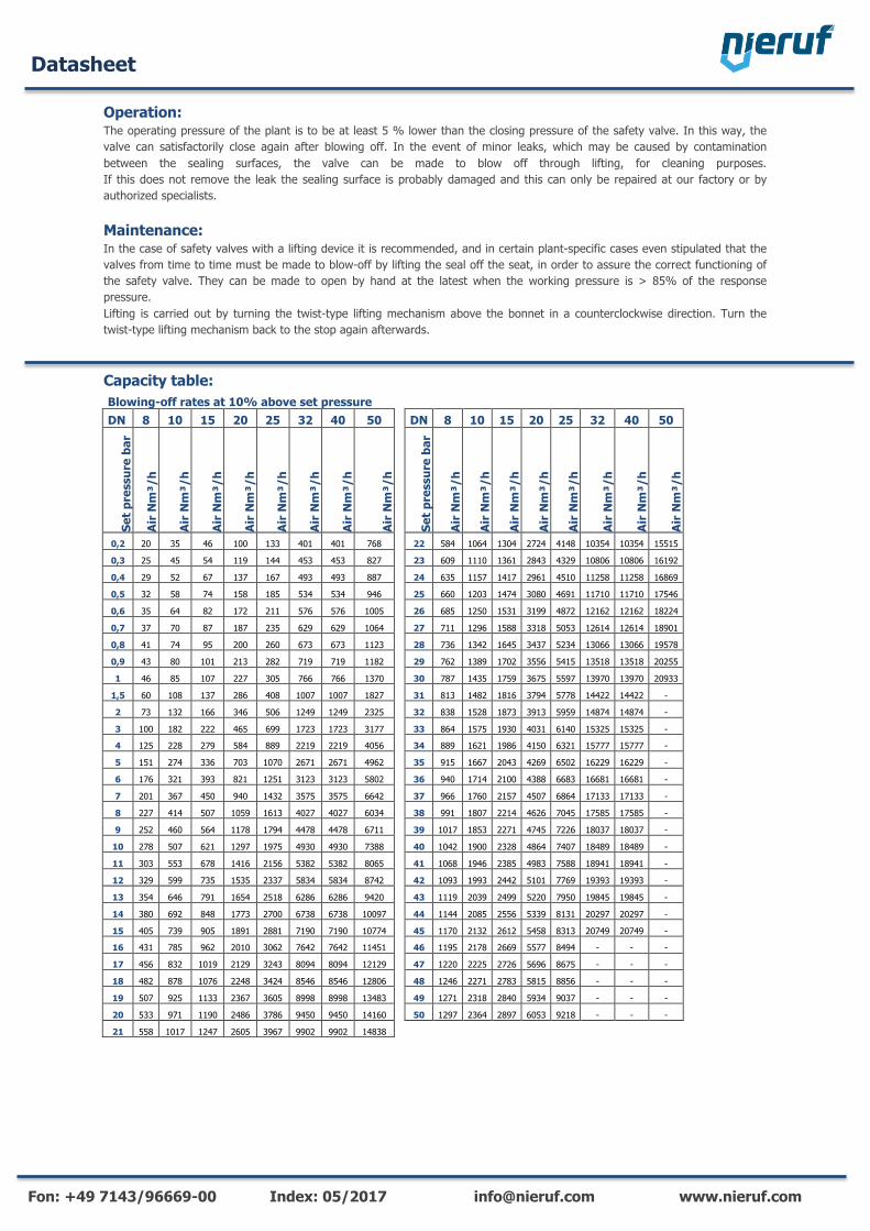
Operation: The operating pressure of the plant is to be at least 5 % lower than the closing pressure of the safety valve. In this way, the valve can satisfactorily close again after blowing off. In the event of minor leaks, which may be caused by contamination between the sealing surfaces, the valve can be made to blow off through lifting, for cleaning purposes. If this does not remove the leak the sealing surface is probably damaged and this can only be repaired at our factory or by authorized specialists. Maintenance: In the case of safety valves with a lifting device it is recommended, and in certain plant-specific cases even stipulated that the valves from time to time must be made to blow-off by lifting the seal off the seat, in order to assure the correct functioning of the safety valve. They can be made to open by hand at the latest when the working pressure is > 85% of the response pressure. Lifting is carried out by turning the twist-type lifting mechanism above the bonnet in a counterclockwise direction. Turn the twist-type lifting mechanism back to the stop again afterwards. Capacity table:Blowing-off rates at 10% above set pressure DN 8 10 15 20 25 32 40 50 DN 8 10 15 20 25 32 40 50
Set p
ress
ure
bar
Air
Nm
³/h
Air
Nm
³/h
Air
Nm
³/h
Air
Nm
³/h
Air
Nm
³/h
Air
Nm
³/h
Air
Nm
³/h
Air
Nm
³/h
Set p
ress
ure
bar
Air
Nm
³/h
Air
Nm
³/h
Air
Nm
³/h
Air
Nm
³/h
Air
Nm
³/h
Air
Nm
³/h
Air
Nm
³/h
Air
Nm
³/h
0,2 20 35 46 100 133 401 401 768 22 584 1064 1304 2724 4148 10354 10354 15515
0,3 25 45 54 119 144 453 453 827 23 609 1110 1361 2843 4329 10806 10806 16192
0,4 29 52 67 137 167 493 493 887 24 635 1157 1417 2961 4510 11258 11258 16869
0,5 32 58 74 158 185 534 534 946 25 660 1203 1474 3080 4691 11710 11710 17546
0,6 35 64 82 172 211 576 576 1005 26 685 1250 1531 3199 4872 12162 12162 18224
0,7 37 70 87 187 235 629 629 1064 27 711 1296 1588 3318 5053 12614 12614 18901
0,8 41 74 95 200 260 673 673 1123 28 736 1342 1645 3437 5234 13066 13066 19578
0,9 43 80 101 213 282 719 719 1182 29 762 1389 1702 3556 5415 13518 13518 20255
1 46 85 107 227 305 766 766 1370 30 787 1435 1759 3675 5597 13970 13970 20933
1,5 60 108 137 286 408 1007 1007 1827 31 813 1482 1816 3794 5778 14422 14422 -
2 73 132 166 346 506 1249 1249 2325 32 838 1528 1873 3913 5959 14874 14874 -
3 100 182 222 465 699 1723 1723 3177 33 864 1575 1930 4031 6140 15325 15325 -
4 125 228 279 584 889 2219 2219 4056 34 889 1621 1986 4150 6321 15777 15777 -
5 151 274 336 703 1070 2671 2671 4962 35 915 1667 2043 4269 6502 16229 16229 -
6 176 321 393 821 1251 3123 3123 5802 36 940 1714 2100 4388 6683 16681 16681 -
7 201 367 450 940 1432 3575 3575 6642 37 966 1760 2157 4507 6864 17133 17133 -
8 227 414 507 1059 1613 4027 4027 6034 38 991 1807 2214 4626 7045 17585 17585 -
9 252 460 564 1178 1794 4478 4478 6711 39 1017 1853 2271 4745 7226 18037 18037 -
10 278 507 621 1297 1975 4930 4930 7388 40 1042 1900 2328 4864 7407 18489 18489 -
11 303 553 678 1416 2156 5382 5382 8065 41 1068 1946 2385 4983 7588 18941 18941 -
12 329 599 735 1535 2337 5834 5834 8742 42 1093 1993 2442 5101 7769 19393 19393 -
13 354 646 791 1654 2518 6286 6286 9420 43 1119 2039 2499 5220 7950 19845 19845 -
14 380 692 848 1773 2700 6738 6738 10097 44 1144 2085 2556 5339 8131 20297 20297 -
15 405 739 905 1891 2881 7190 7190 10774 45 1170 2132 2612 5458 8313 20749 20749 -
16 431 785 962 2010 3062 7642 7642 11451 46 1195 2178 2669 5577 8494 - - -
17 456 832 1019 2129 3243 8094 8094 12129 47 1220 2225 2726 5696 8675 - - -
18 482 878 1076 2248 3424 8546 8546 12806 48 1246 2271 2783 5815 8856 - - -
19 507 925 1133 2367 3605 8998 8998 13483 49 1271 2318 2840 5934 9037 - - -
20 533 971 1190 2486 3786 9450 9450 14160 50 1297 2364 2897 6053 9218 - - -
21 558 1017 1247 2605 3967 9902 9902 14838
Datasheet
Fon: +49 7143/96669-00 Index: 05/2017 [email protected] www.nieruf.com
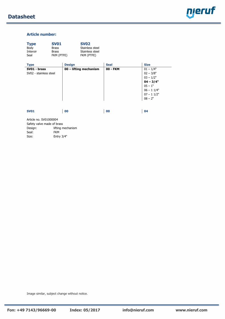
Article number:
Type Design Seal Size SV01 - brass SV02 - stainless steel
00 – lifting mechanism
00 - FKM
01 – 1/4“ 02 – 3/8“ 03 – 1/2“ 04 – 3/4“ 05 – 1“ 06 – 1 1/4“ 07 – 1 1/2“ 08 – 2“
SV01 00 00 04 Article no. SV01000004 Safety valve made of brass Design: lifting mechanism Seal: FKM Size: Entry 3/4“
Image similar, subject change without notice.
Type SV01 SV02 Body Brass Stainless steel Interoir Brass Stainless steel Seal FKM (PTFE) FKM (PTFE)