Embed Size (px)
DESCRIPTION
sdftser
Citation preview
What’s in the box?
What do I need to fit it?
How to install the VHF on desktop and overhead
How to install the VHF flush mount
INSTALLATION GUIDE
SAILOR 6222 VHF DSC
Thrane & Thrane A/S • [email protected] • www.thrane.com
98-132281-A
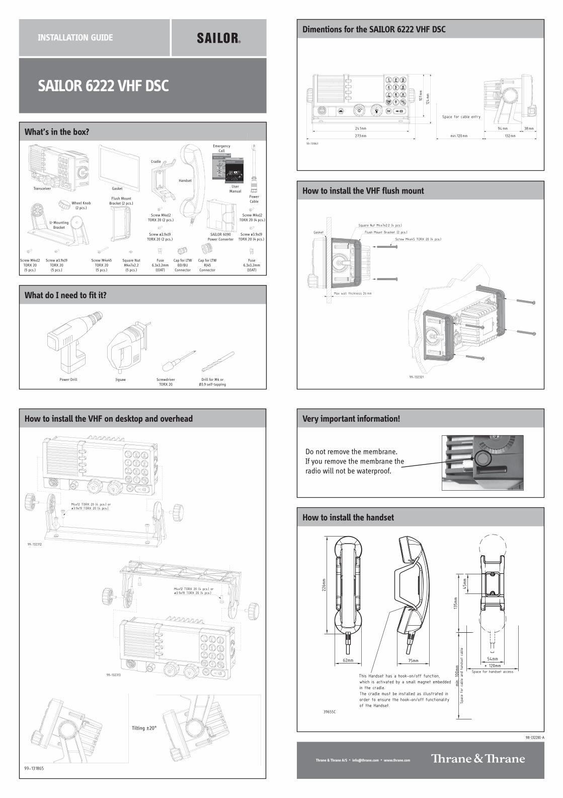
How to install the handset
Power Drill Jigsaw ScrewdriverTORX 20
Drill for M4 orØ3.9 self-tapping
U-MountingBracket
Transceiver Gasket
Flush MountBracket (2 pcs.)
Fuse6.3x3.2mm
(10AT)
Cradle
Wheel Knob(2 pcs.)
Screw M4x45TORX 20(5 pcs.)
Square NutM4x7x2.2(5 pcs.)
Screw M4x12TORX 20 (2 pcs.)
Screw ø3.9x19TORX 20 (2 pcs.)
Screw M4x12TORX 20(5 pcs.)
Screw ø3.9x19TORX 20(5 pcs.)
Handset
Very important information!
Do not remove the membrane.If you remove the membrane theradio will not be waterproof.
This Handset has a hook-on/off function,
which is activated by a small magnet embedded
in the cradle.
The cradle must be installed as illustrated in
order to ensure the hook-on/off functionality
of the Handset.
75mm62mm
226mm
* 120mm
min. 100mm
Space for handset access
Space for cable and handset cable
54mm
45mm
135mm
39655C
Tilting ±20°
Dimentions for the SAILOR 6222 VHF DSC
Cap for LTWRJ45
Connector
Cap for LTWBD/BU
Connector
Fuse6.3x3.2mm
(10AT)
Screw M4x12TORX 20 (4 pcs.)
Screw ø3.9x19TORX 20 (4 pcs.)
SAILOR 6090Power Converter
UserManual
EmergencyCall
EMERGENCY CALL
SAILOR VHF and MF/HF
MMMMMAAAAAYYYYYDDDDDAAAAAYYYYYNANANANANAMEMEMEMEME of the VVVVVEEEEESSSSSSSSSSELELELELEL in distress
CCCCCALALALALALLLLLLSSSSSIGNIGNIGNIGNIGN or other IDENIDENIDENIDENIDENTTTTTIFICIFICIFICIFICIFICAAAAATTTTTIONIONIONIONIONMMMMMMMMMMSSSSSIIIII
(If the initial alert is sent by DSC)
PPPPPOOOOOSSSSSITITITITITIONIONIONIONIONgiven as lllllatatatatatitititititudeudeudeudeude and longitlongitlongitlongitlongitudeudeudeudeude
orIf latitude and longitude are not known
or if time is insufficient,in relation to a known geographical location
NANANANANATURETURETURETURETURE of distressKind of AAAAASSSSSSSSSSIIIIISSSSSTTTTTANCANCANCANCANCEEEEE required
Any other useful INFINFINFINFINFORORORORORMMMMMAAAAATTTTTIONIONIONIONION
MMMMMAAAAAYYYYYDDDDDAAAAAYYYYY-M-M-M-M-MAAAAAYYYYYDDDDDAAAAAYYYYY-M-M-M-M-MAAAAAYYYYYDDDDDAAAAAYYYYYThis is
NANANANANAME-NAME-NAME-NAME-NAME-NAME-NAME-NAME-NAME-NAME-NAMEMEMEMEME
CCCCCALALALALALLLLLLSSSSSIGNIGNIGNIGNIGNor other IDENTIFICATION
MMMMMMMMMMSSSSSIIIII(If the initial alert is sent by DSC)
Use the HANDHANDHANDHANDHANDSSSSSETETETETET for voice calling
LLLLLififififift Ct Ct Ct Ct Covovovovovererererer
PPPPPrrrrreeeeessssss RED Buttons RED Buttons RED Buttons RED Buttons RED Buttonuntil beep sounds continuously(more than 3 seconds)
SHIP‘s NAME:
CALLSIGN:
MMSI:
OWN OWN OWN OWN OWN IDIDIDIDID
99-132140
Press
VHFMFHF4HF6HF8HF12HF16
Channel 702187.5 kHz4207.5 kHz6312.0 kHz8414.5 kHz
12577.0 kHz16804.5 kHz
Channel 162182.0 kHz4125.0 kHz6215.0 kHz8291.0 kHz
12290.0 kHz16420.0 kHz
- - - - -2174.5 kHz4177.5 kHz
6268.0 kHz8376.5 kHz
12520.0 kHz16695.0 kHz
DDDDDSCSCSCSCSC RRRRRadiadiadiadiadiotototototelephonelephonelephonelephonelephonyyyyy NBDPNBDPNBDPNBDPNBDP
DIDIDIDIDISSSSSTRETRETRETRETRESSSSSSSSSS and C and C and C and C and COMOMOMOMOMMMMMMUNICUNICUNICUNICUNICAAAAATTTTTIONIONIONIONIONFREQUENCIEFREQUENCIEFREQUENCIEFREQUENCIEFREQUENCIESSSSS
_ _ _ _ _ _ _ _ _ _ _ _ _ _ _ _ _ _ _ _ _ _ _ _ _ _ _ _ _ _ _ _ _ _ _ _Remember to use the correct HF-proceduresDon‘t forget your EPIRB is the secondary means ofalerting
_ _ _ _ _ _ _ _ _ _ _ _ _ _ _ _ _ _ _ _ _ _ _ _ _ _ _ _ _ _ _ _ _ _ _ _
98-132369-A
SAILOR 6222 VHF DSC
USER MANUAL
PowerCable
Flush mount template
Remove material from shaded area only!
89mm
227mm
R2.5mm x 4
Thrane & Thrane A/S • [email protected] • www.thrane.com
98-132281-A
Scale 1:1
Cutout template for flush mounting of the VHF
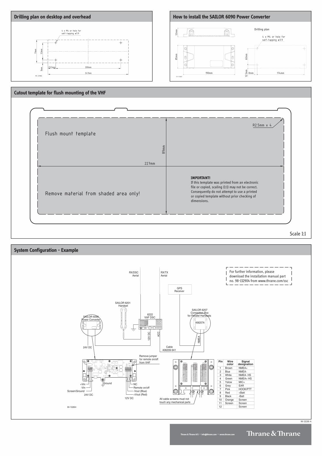
VHF DSC
ReceiverGPS
99-132804
6222
HandsetSAILOR 6201
Power ConverterSAILOR 6090
12V
DC
SAILOR 6207Connection Box
for Parallel Handsets
406209-941Cable
406207A
NM
EAA
CC
Ground
12V DC+Vout (Red)-Vout (Blue)Remote on/offNC
Screen/Ground-Vin
+Vin
24V DC
Remove jumperfor remote on/offfrom VHF
color designationWire SignalPin
All cable screens must nottouch any mechanical parts
BrownBlueWhiteGreenYelowGreyPinkRedBlackOrangeScreen
NMEA+NMEA-NMEA- HSNMEA+ HSMIC+EARHOOK/PTT+Batt-BattScreenScreenScreen
123456789
101112
J1 J2 J3
1
2
3
4
5
6
7
8
9
10
11
12
1
2
3
4
5
6
7
8
9
10
11
1212
11
VHF 62XXHandset 2Handset 1
10
9
8
7
6
5
4
3
2
1
AerialRX/TX
AerialRX/DSC
24V DC
IMPIMPIMPIMPIMPORORORORORTTTTTANANANANANT!T!T!T!T!If this template was printed from an electronicfile or copied, scaling (1:1) may not be correct.Consequently do not attempt to use a printedor copied template without prior checking ofdimensions.
System Configuration - Example
Drilling plan on desktop and overhead How to install the SAILOR 6090 Power Converter
Drilling plan
99-131985
200mm
53mm
71mm
247mm
9mm
4 x M4 or hole for
self-tapping ø3.9
23.5mm
For further information, pleasedownload the installation manual partno. 98-132904 from www.thrane.com/ssc