Embed Size (px)
Citation preview
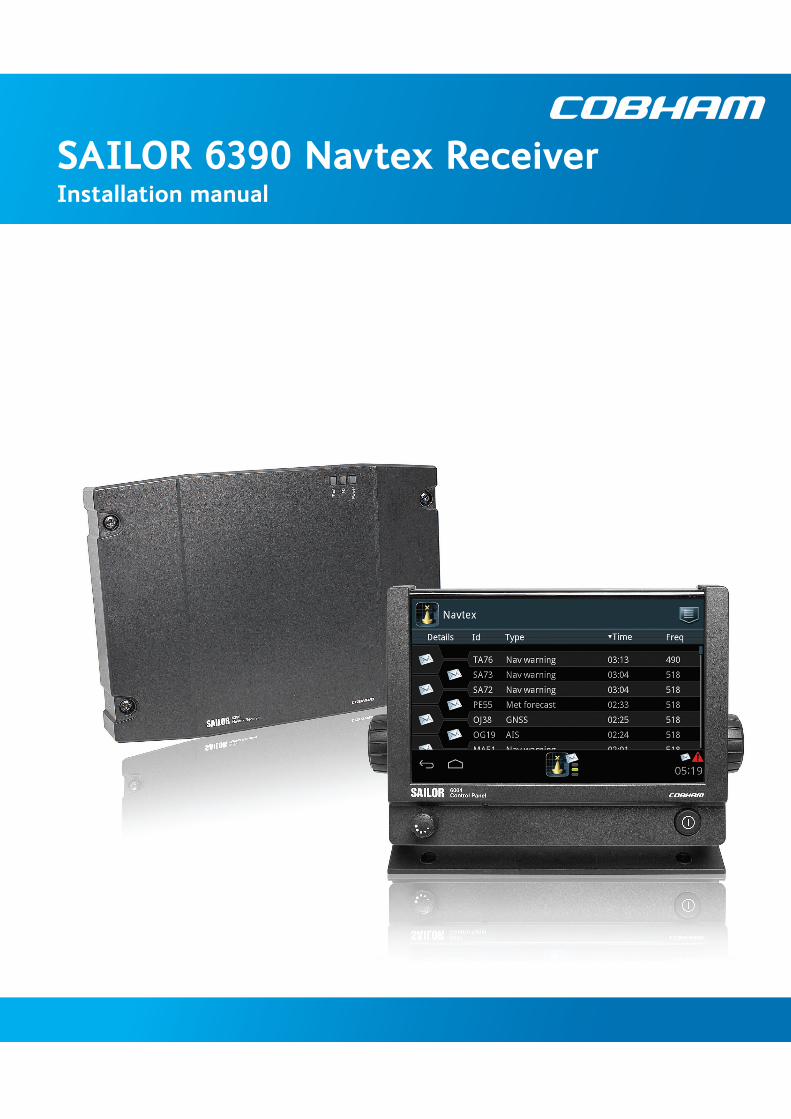
SAILOR 6390 Navtex ReceiverInstallation manual

SAILOR 6390 Navtex Receiver
Installation manual
Document number: 98-139768-B
Release date: February 26, 2014
ii 98-139768-B
Disclaimer
Any responsibility or liability for loss or damage in connection with the use of this product and the accompanying documentation is disclaimed by Thrane & Thrane A/S. The information in this manual is provided for information purposes only, is subject to change without notice and may contain errors or inaccuracies. Manuals issued by Thrane & Thrane A/S are periodically revised and updated. Anyone relying on this information should acquire the most current version e.g. from www.cobham.com/satcom or from the distributor. Thrane & Thrane A/S is not responsible for the content or accuracy of any translations or reproductions, in whole or in part, of this manual from any other source.
Thrane & Thrane A/S is trading as Cobham SATCOM.
Copyright
© 2014 Thrane & Thrane A/S. All rights reserved.
Trademark acknowledgements
• SAILOR is a registered trademark of Thrane & Thrane A/S in the European Union, the United States of America and other countries.
• Other product and company names mentioned in this manual may be trademarks or trade names of their respective owners.
• This product contains Android™ software (a Google Inc. trademark).
GPL notification
The software included in this product contains copyrighted software that is licensed under the GPL/LGPL. The verbatim licenses can be found online at:
http://www.gnu.org/licenses/old-licenses/gpl-2.0.html
http://www.gnu.org/licenses/old-licenses/lgpl-2.1.html
You may obtain the complete corresponding source code from us for a period of three years after our last shipment of this product, which will be no earlier than 2021, by sending a money order or check for DKK 50 to:
SW Technology/GPL Compliance,Thrane & Thrane A/S,Lundtoftegaardsvej 93D2800 LyngbyDENMARK
Please write "source for product SAILOR 6390 Navtex Receiver" in the memo line of your payment. This offer is valid to anyone in receipt of this information.
98-139768-B iii
Safety summaryObserve the following general safety precautions during all phases of operation, service and repair of this equipment. Failure to comply with these precautions or with specific warnings elsewhere in this manual violates safety standards of design, manufacture and intended use of the equipment. Thrane & Thrane A/S assumes no liability for the customer's failure to comply with these requirements.
Ground the equipmentTo minimise shock hazard, connect the SAILOR 6390 Navtex Receiver to an electrical ground and follow the cable instructions.
Warranty limitationThe SAILOR 6390 Navtex Receiver is not a user maintainable unit, and under no circumstances should the unit be opened beyond the outer plastic cover, except by authorized personnel. Unauthorized opening of the unit will invalidate the warranty.
Installation and serviceInstallation and general service must be done by skilled service personnel. The SAILOR 6390 Navtex Receiver is intended for use in a protected environment (-15° to +55°C) according to IEC-60945.
Compass safe distanceCompass safe distance: 20 cm (Standard magnetic compass), 20 cm (Emergency magnetic compass) from the SAILOR 6390 Navtex Receiver.
iv 98-139768-B
Preface
Approvals and standard complianceSAILOR 6390 Navtex Receiver is approved to MED 2012/32/EU and fulfills the requirements in the following standards:
IEC-60945 (2002), IEC-60945 Corrigendum 1 (2008), IEC-61097-6 (2005-12), IEC-61162-1 (2010-11) (aligned with NMEA 0183 version 4.00), ITU-T X.27/V.11 (1996)
The SAILOR 6390 Navtex Receiver is approved to SOLAS Regulations IV/7, IV/14: ITU-R M.540-2 (06/90) and ITU-R M.625-3 (10/95).
The SAILOR 6390 Navtex Receiver is approved to FCC Equipment class: RNV, Part 80 NAVTEX Receiver 80.1101(c)(1).
The approvals of the SAILOR 6390 Navtex Receiver are constantly monitored. New national approvals will be applied for and granted and new test standards may come into force. Therefore the above list may not be complete. Contact your authorized dealer for more information.
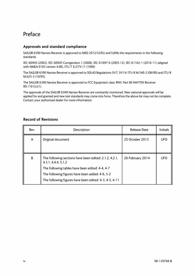
Record of Revisions
Rev. Description Release Date Initials
A Original document 25 October 2013 UFO
B The following sections have been edited: 2.1.2, 4.2.1, 4.3.1, 4.4.4, 5.1.2
The following tables have been edited: 4-4, 4-7
The following figures have been added: 4-6, 5-2
The following figures have been edited: 4-3, 4-5, 4-11
26 February 2014 UFO
98-139768-B v
Table of contents
Chapter 1 About this manual1.1 Intended readers ..............................................................................................................1-1
1.2 Manual overview ...............................................................................................................1-1
1.3 Related documentation ...............................................................................................1-1
1.4 Precautions ............................................................................................................................1-2
Chapter 2 Introduction2.1 Introduction to Navtex ...............................................................................................2-12.1.1 Overview ..................................................................................................................................2-12.1.2 Features ...................................................................................................................................2-22.1.3 Connector overview ..........................................................................................................2-22.1.4 Navtex message (example) ............................................................................................2-2
2.2 System components .......................................................................................................2-32.2.1 Use with the SAILOR 6004 Control panel ...............................................................2-32.2.2 Use as a stand-alone unit with an INS ......................................................................2-4
2.3 Part numbers ........................................................................................................................2-4
Chapter 3 Installation3.1 Unpacking and initial inspection ..........................................................................3-13.1.1 Unpacking ...............................................................................................................................3-13.1.2 Initial inspection ..................................................................................................................3-1
3.2 Installation of the SAILOR 6390 Navtex Receiver ................................3-23.2.1 Dimensions .............................................................................................................................3-23.2.2 Drilling plan ............................................................................................................................3-33.2.3 Navtex antenna ....................................................................................................................3-33.2.4 Wiring ........................................................................................................................................3-43.2.5 Ethernet interfaces .............................................................................................................3-53.2.6 Recommended cables .......................................................................................................3-6
3.3 Installation of the SAILOR 6004 Control panel .......................................3-6
Chapter 4 Configuration4.1 Start up .....................................................................................................................................4-14.1.1 To Power on and off ..........................................................................................................4-14.1.2 Dim and night mode ..........................................................................................................4-1
4.2 System and Navtex app installation .................................................................4-24.2.1 System app .............................................................................................................................4-24.2.2 Navtex app – daily use ......................................................................................................4-3
Table of contents
vi 98-139768-B
4.3 Configuration with the Service Interface .....................................................4-44.3.1 To access the Service Interface ...................................................................................4-44.3.2 Configuring the installation ............................................................................................4-64.3.3 Interface settings ................................................................................................................4-84.3.4 Managing Coast Station lists ......................................................................................4-144.3.5 System Control ..................................................................................................................4-164.3.6 Reboot Device ...................................................................................................................4-16
4.4 Verification .........................................................................................................................4-174.4.1 Verifying the installation ..............................................................................................4-174.4.2 NMEA Trace tool ..............................................................................................................4-184.4.3 Checking RF Reception Levels ....................................................................................4-194.4.4 Installation Tests ..............................................................................................................4-20
Chapter 5 Service & maintenance5.1 Maintenance ........................................................................................................................5-15.1 Contact for support ...........................................................................................................5-15.1.1 System Log .............................................................................................................................5-15.1.2 Software update ..................................................................................................................5-25.1.3 Disassembling – removing the cover .........................................................................5-45.1.4 Replacing the fuse ...............................................................................................................5-4
5.2 Alarms and notifications ............................................................................................5-55.2.1 Installation with SAILOR 6004 Control Panel .......................................................5-55.2.2 Installation with an INS ....................................................................................................5-6
5.3 Troubleshooting guide .................................................................................................5-7
5.4 Warranty and returning units for repair ......................................................5-105.4.1 Repacking for shipment ................................................................................................5-10
Appendix A Technical specificationsA.1 SAILOR 6390 Navtex Receiver .............................................................................. A-1
A.2 NMEA PCB in SAILOR 6390 Navtex Receiver ............................................ A-2
Appendix B NMEA sentencesB.1 NMEA sentences used ..................................................................................................B-1B.1.1 Light Weight Ethernet – LWE ........................................................................................B-1B.1.2 Sentence characteristics and their linkage with port configuration ...........B-2
Table of contents
98-139768-B vii
B.2 Sentence use reference ...............................................................................................B-3B.2.1 Overview ..................................................................................................................................B-3B.2.2 ACK - Acknowledge alarm (input) ...............................................................................B-3B.2.3 ALR - Set alarm state ..........................................................................................................B-4B.2.4 CRQ ............................................................................................................................................B-4B.2.5 NRM - NAVTEX receiver mask (input/output) .......................................................B-4B.2.6 NRX - NAVTEX received message (output) .............................................................B-5B.2.7 RMC - Recommended minimum specific GNSS data (input) .........................B-6B.2.8 ZDA - Time and Date (input/output) .........................................................................B-6
Glossary ..............................................................................................................................................................Glossary-1
Index ................................................................................................................................................................... Index-1

Table of contents
viii 98-139768-B
98-139768-B 1-1
Chapter 11111
Abou
t thi
s man
ual
About this manual 1
1.1 Intended readersThis is an installation manual for the SAILOR 6390 Navtex Receiver. It is intended for installers of the system and service personnel. Personnel installing or servicing the system must be properly trained by Cobham SATCOM. It is important that you observe all safety requirements listed in the beginning of this manual, and install the system according to the guidelines in this manual. For daily use see the SAILOR 6390 Navtex Receiver User manual.
1.2 Manual overviewThis manual has the following chapters and appendices:
• Introduction
• Installation
• Configuration
• Service & maintenance
• Technical specifications
• NMEA sentences
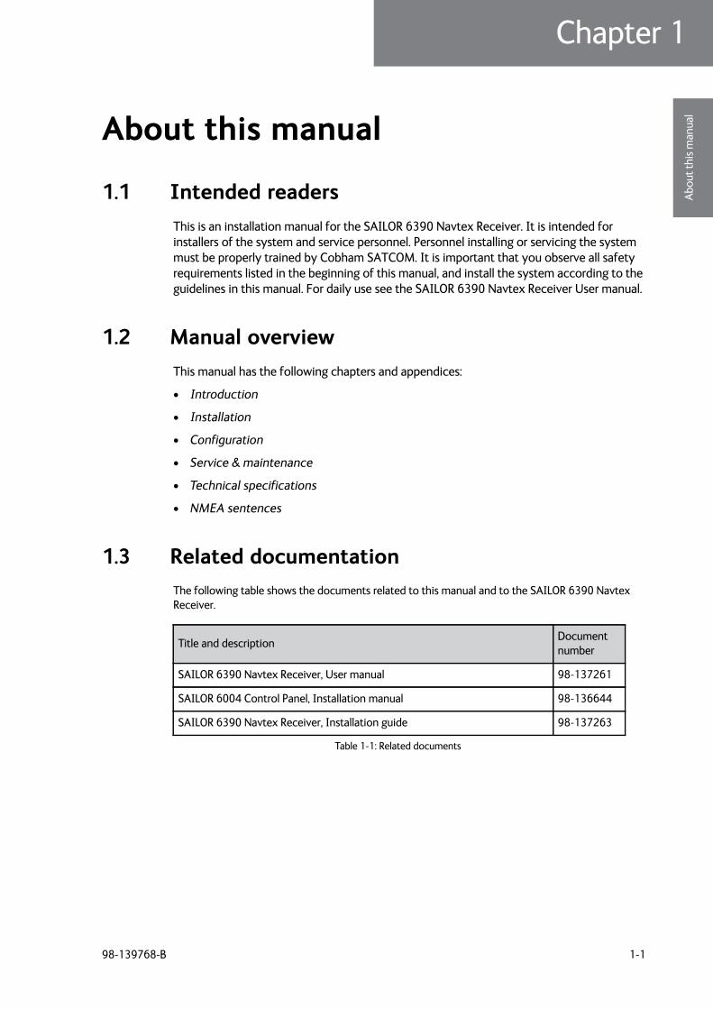
1.3 Related documentationThe following table shows the documents related to this manual and to the SAILOR 6390 Navtex Receiver.
Title and description Document number
SAILOR 6390 Navtex Receiver, User manual 98-137261
SAILOR 6004 Control Panel, Installation manual 98-136644
SAILOR 6390 Navtex Receiver, Installation guide 98-137263
Table 1-1: Related documents
Precautions
1-2 Chapter 1: About this manual 98-139768-B
1.4 Precautions
Warnings, Cautions and Notes
Text marked with “Warning”, “Caution”, “Note” or “Important” show the following type of data:
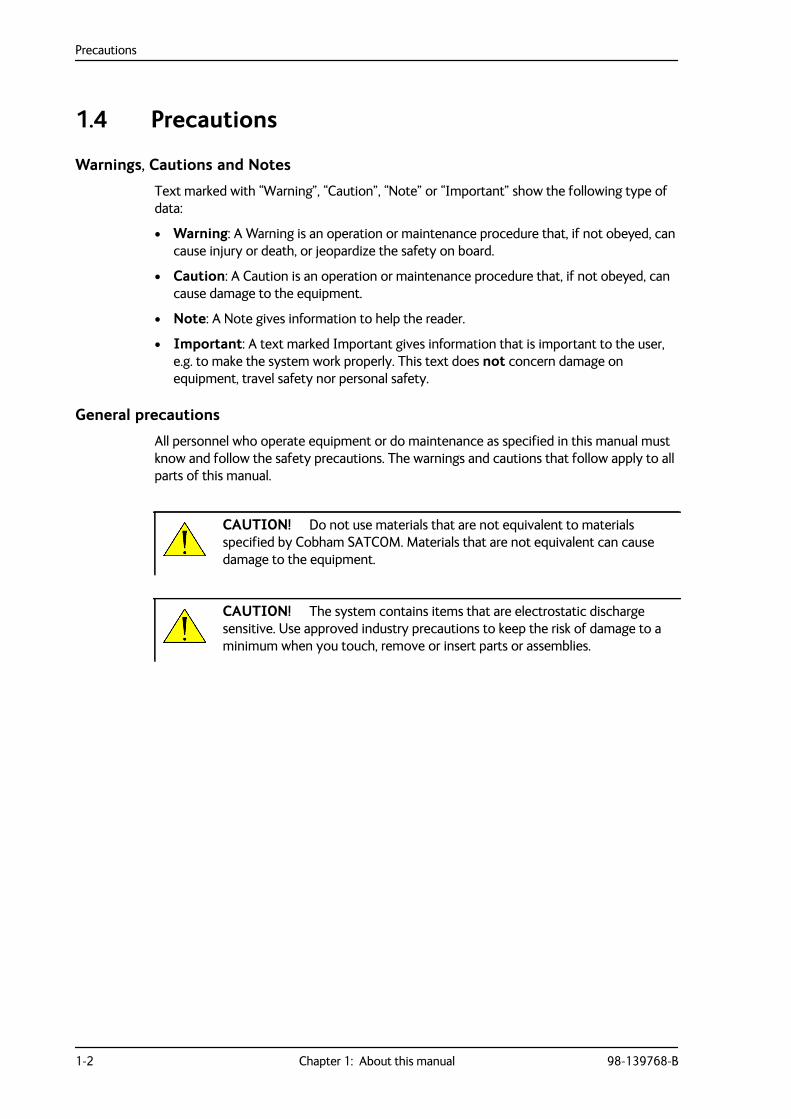
• Warning: A Warning is an operation or maintenance procedure that, if not obeyed, can cause injury or death, or jeopardize the safety on board.
• Caution: A Caution is an operation or maintenance procedure that, if not obeyed, can cause damage to the equipment.
• Note: A Note gives information to help the reader.
• Important: A text marked Important gives information that is important to the user, e.g. to make the system work properly. This text does not concern damage on equipment, travel safety nor personal safety.
General precautions
All personnel who operate equipment or do maintenance as specified in this manual must know and follow the safety precautions. The warnings and cautions that follow apply to all parts of this manual.
CAUTION! Do not use materials that are not equivalent to materials specified by Cobham SATCOM. Materials that are not equivalent can cause damage to the equipment.
CAUTION! The system contains items that are electrostatic discharge sensitive. Use approved industry precautions to keep the risk of damage to a minimum when you touch, remove or insert parts or assemblies.
98-139768-B 2-1
Chapter 22222
Intr
oduc
tion
Introduction 2
This chapter has the following sections:
• Introduction to Navtex
• Navtex message (example)
• System components
• Part numbers
2.1 Introduction to Navtex
2.1.1 Overview
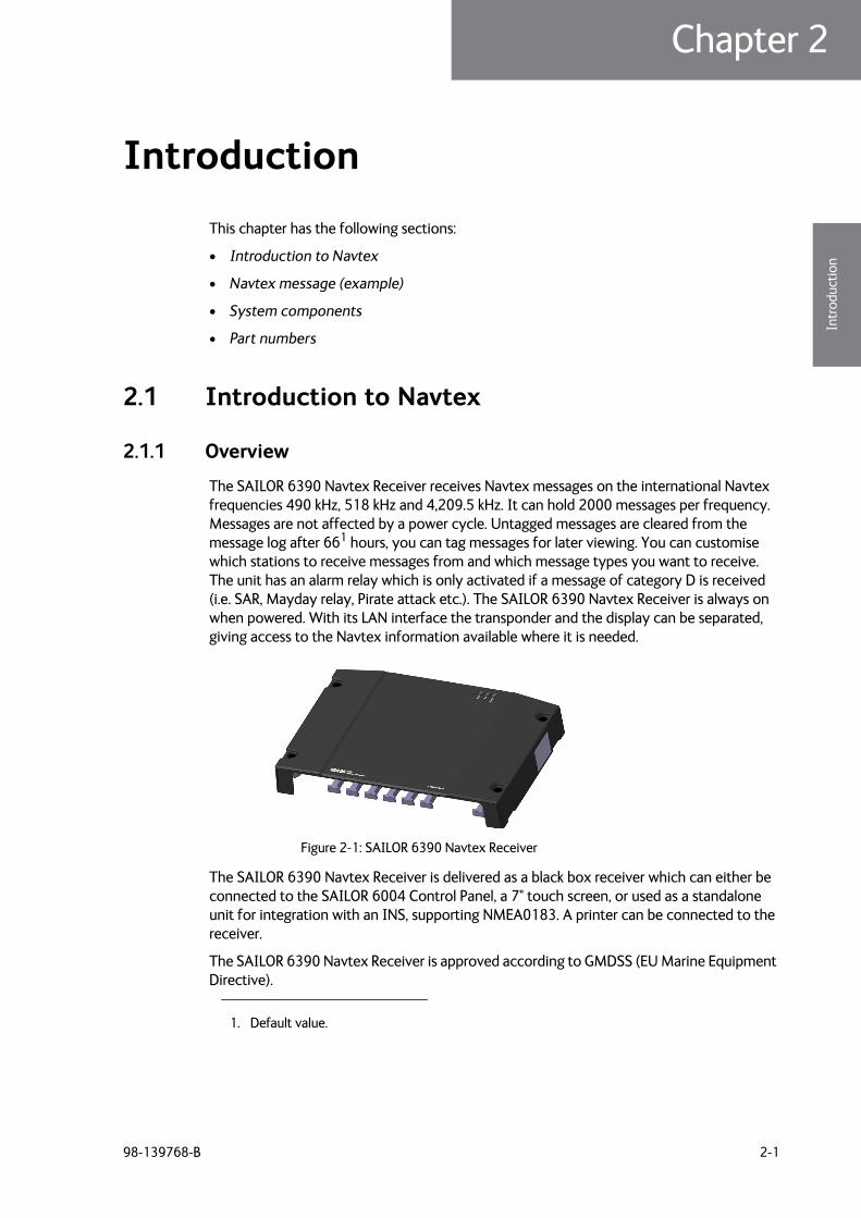
The SAILOR 6390 Navtex Receiver receives Navtex messages on the international Navtex frequencies 490 kHz, 518 kHz and 4,209.5 kHz. It can hold 2000 messages per frequency. Messages are not affected by a power cycle. Untagged messages are cleared from the message log after 661 hours, you can tag messages for later viewing. You can customise which stations to receive messages from and which message types you want to receive. The unit has an alarm relay which is only activated if a message of category D is received (i.e. SAR, Mayday relay, Pirate attack etc.). The SAILOR 6390 Navtex Receiver is always on when powered. With its LAN interface the transponder and the display can be separated, giving access to the Navtex information available where it is needed.
The SAILOR 6390 Navtex Receiver is delivered as a black box receiver which can either be connected to the SAILOR 6004 Control Panel, a 7" touch screen, or used as a standalone unit for integration with an INS, supporting NMEA0183. A printer can be connected to the receiver.
The SAILOR 6390 Navtex Receiver is approved according to GMDSS (EU Marine Equipment Directive).
1. Default value.
Figure 2-1: SAILOR 6390 Navtex Receiver
Introduction to Navtex
2-2 Chapter 2: Introduction 98-139768-B
2.1.2 Features
2000 messages per frequency, giving a total of 6000 messages
Printing via SAILOR 6004 Control Panel and 3rd party line printer over LAN
Integrated Navtex app for SAILOR 6004 Control Panel
Low and high impedance antenna switch
Dual LAN connector
TMA (ThraneLINK Management Application) for software upgrade
Storage of Navtex messages on a USB storage device
Prepared for 500 kHz NAVDAT (Software update)
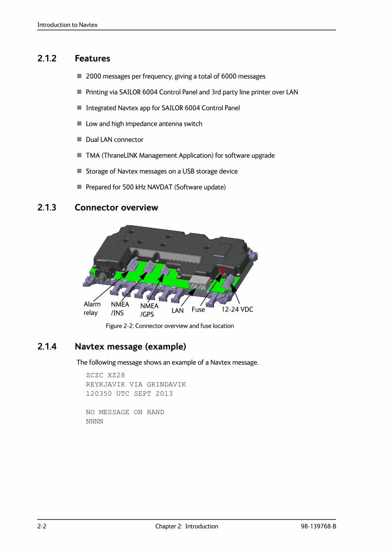
2.1.3 Connector overview
2.1.4 Navtex message (example)
The following message shows an example of a Navtex message.
ZCZC XZ28REYKJAVIK VIA GRINDAVIK 120350 UTC SEPT 2013
NO MESSAGE ON HAND NNNN
Figure 2-2: Connector overview and fuse location
12-24 VDCNMEA/INS
Alarm relay
NMEA/GPS LAN Fuse
System components
98-139768-B Chapter 2: Introduction 2-3
2222
Intr
oduc
tion
2.2 System componentsThe SAILOR 6390 Navtex Receiver can be used in the following contexts:
• Use with the SAILOR 6004 Control panel
• Use as a stand-alone unit with an INS
An optional printer can be connected in both use scenarios.
2.2.1 Use with the SAILOR 6004 Control panel
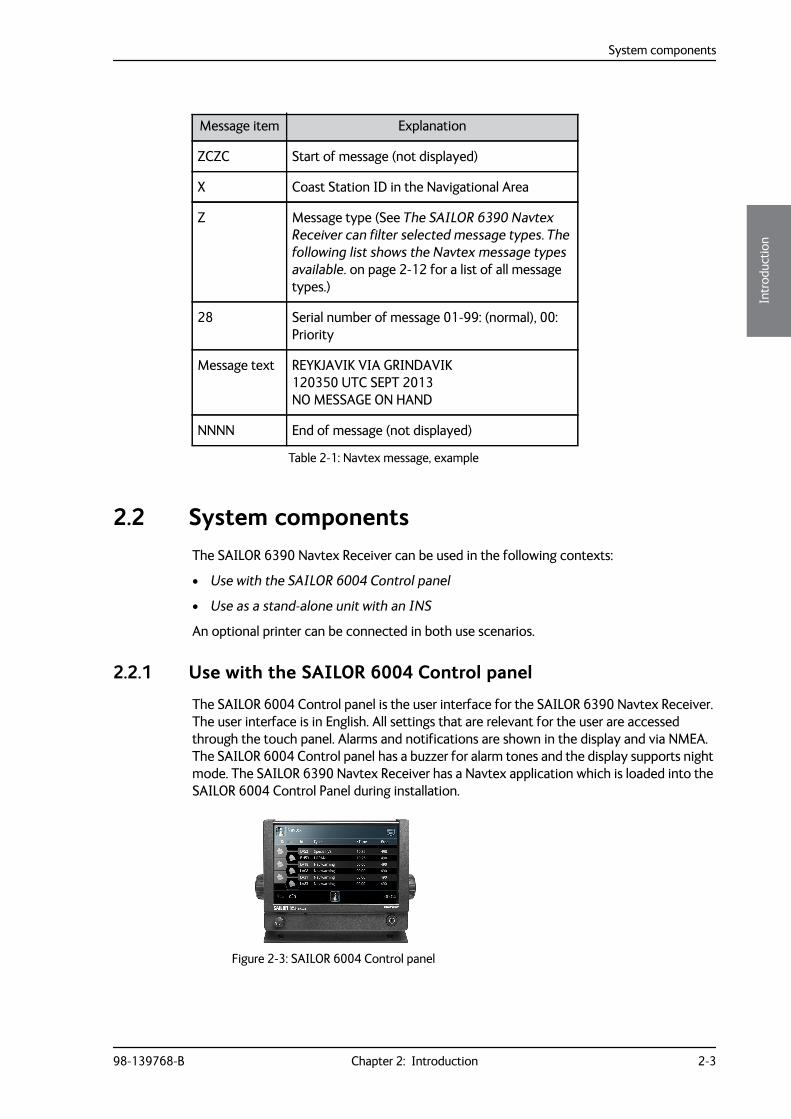
The SAILOR 6004 Control panel is the user interface for the SAILOR 6390 Navtex Receiver. The user interface is in English. All settings that are relevant for the user are accessed through the touch panel. Alarms and notifications are shown in the display and via NMEA. The SAILOR 6004 Control panel has a buzzer for alarm tones and the display supports night mode. The SAILOR 6390 Navtex Receiver has a Navtex application which is loaded into the SAILOR 6004 Control Panel during installation.
Message item Explanation
ZCZC Start of message (not displayed)
X Coast Station ID in the Navigational Area
Z Message type (See The SAILOR 6390 Navtex Receiver can filter selected message types. The following list shows the Navtex message types available. on page 2-12 for a list of all message types.)
28 Serial number of message 01-99: (normal), 00: Priority
Message text REYKJAVIK VIA GRINDAVIK120350 UTC SEPT 2013 NO MESSAGE ON HAND
NNNN End of message (not displayed)
Table 2-1: Navtex message, example
Figure 2-3: SAILOR 6004 Control panel
Part numbers
2-4 Chapter 2: Introduction 98-139768-B
2.2.2 Use as a stand-alone unit with an INS
The SAILOR 6390 Navtex Receiver also works as a stand-alone unit, integrated in the vessel’s INS. It supports the Navtex specific NMEA sentences according to the standard IEC 61097–6 and IEC 61162-1. For further details see the documentation of the INS.
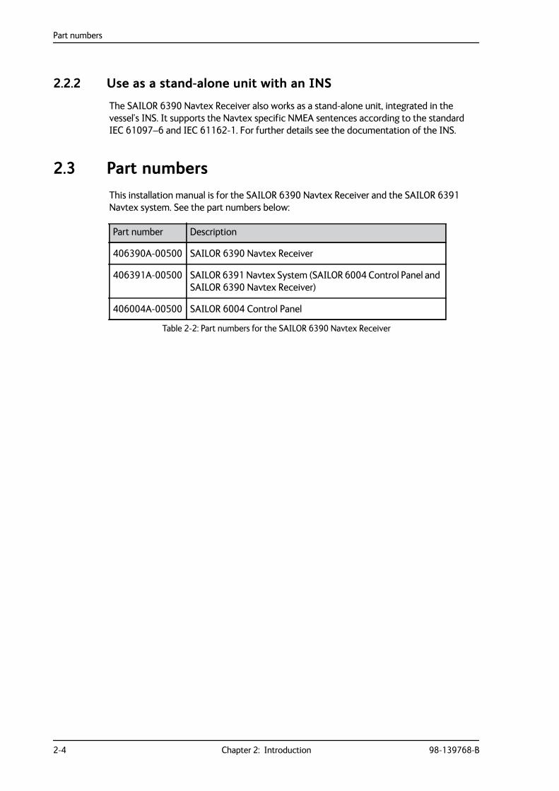
2.3 Part numbersThis installation manual is for the SAILOR 6390 Navtex Receiver and the SAILOR 6391 Navtex system. See the part numbers below:
Part number Description
406390A-00500 SAILOR 6390 Navtex Receiver
406391A-00500 SAILOR 6391 Navtex System (SAILOR 6004 Control Panel and SAILOR 6390 Navtex Receiver)
406004A-00500 SAILOR 6004 Control Panel
Table 2-2: Part numbers for the SAILOR 6390 Navtex Receiver
98-139768-B 3-1
Chapter 33333
Inst
alla
tion
Installation 3
This chapter has the following sections:
• Unpacking and initial inspection
• Installation of the SAILOR 6390 Navtex Receiver
• Installation of the SAILOR 6004 Control panel
3.1 Unpacking and initial inspection
3.1.1 Unpacking
The following items are included in the delivery of a SAILOR 6390 Navtex Receiver:
• SAILOR 6390 Navtex Receiver
• User manual SAILOR 6390 Navtex Receiver
• Installation guide SAILOR 6390 Navtex Receiver
• Cable RJ45 Cat5e STP, 5 m
• Mounting tool for terminal blocks
• Cable tie 5x200 mm (8 pieces)
• Fuse puller
• Fuse (1 A)
• Screw M4-x12 TORX 20 (5 pieces)
• Screw ST3.9x19 TORX (5 pieces)
3.1.2 Initial inspection
Inspect the shipping carton immediately upon receipt for evidence of damage during transport. If the shipping carton is severely damaged or water stained, request that the carrier's agent be present when opening the carton. Save the carton packing material for future use.
After unpacking the system, inspect it thoroughly for hidden damage and loose components or fittings. If the contents are incomplete, if there is mechanical damage or defect, or if the system does not work properly, notify your dealer.
WARNING! To avoid electric shock, do not apply power to the system if there is any sign of shipping damage to any part of the front or rear panel or the outer cover. Read the safety summary at the front of this manual before installing or operating the system.
Installation of the SAILOR 6390 Navtex Receiver
3-2 Chapter 3: Installation 98-139768-B
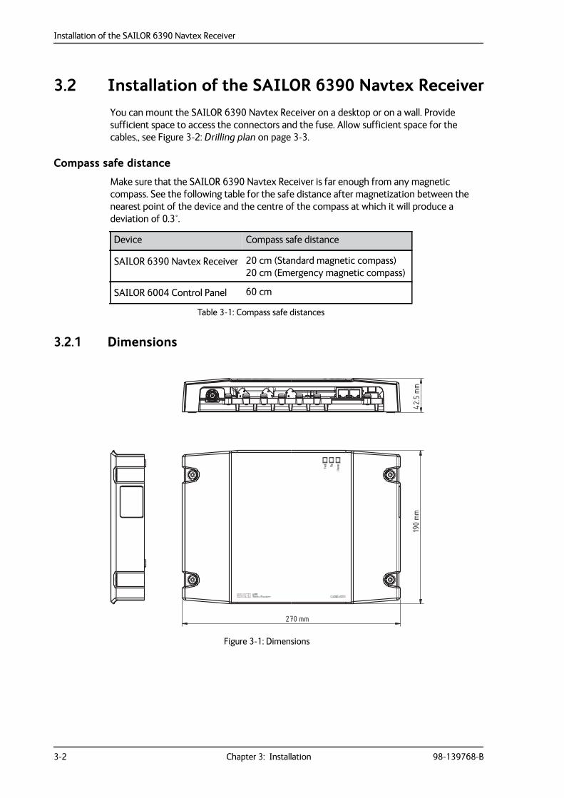
3.2 Installation of the SAILOR 6390 Navtex ReceiverYou can mount the SAILOR 6390 Navtex Receiver on a desktop or on a wall. Provide sufficient space to access the connectors and the fuse. Allow sufficient space for the cables., see Figure 3-2: Drilling plan on page 3-3.
Compass safe distance
Make sure that the SAILOR 6390 Navtex Receiver is far enough from any magnetic compass. See the following table for the safe distance after magnetization between the nearest point of the device and the centre of the compass at which it will produce a deviation of 0.3°.
3.2.1 Dimensions
Device Compass safe distance
SAILOR 6390 Navtex Receiver 20 cm (Standard magnetic compass)20 cm (Emergency magnetic compass)
SAILOR 6004 Control Panel 60 cm
Table 3-1: Compass safe distances
Figure 3-1: Dimensions
190mm
270 mm
42.5
mm
Installation of the SAILOR 6390 Navtex Receiver
98-139768-B Chapter 3: Installation 3-3
3333
Inst
alla
tion
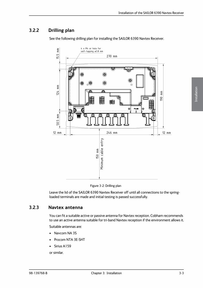
3.2.2 Drilling plan
See the following drilling plan for installing the SAILOR 6390 Navtex Receiver.
Leave the lid of the SAILOR 6390 Navtex Receiver off until all connections to the spring-loaded terminals are made and initial testing is passed successfully.
3.2.3 Navtex antenna
You can fit a suitable active or passive antenna for Navtex reception. Cobham recommends to use an active antenna suitable for tri-band Navtex reception if the environment allows it.
Suitable antennas are:
• Navcom NA 3S
• Procom NTA 3E-SHT
• Sirius A159
or similar.
Figure 3-2: Drilling plan
Minimu
m ca
ble
entr
y
15.5 m
m12
4 mm
50.5 m
m
12 mm 246 mm 12 mm
4 x M4 or hole forself-tapping ø3.8 mm
190
mm
270 mm
150
mm

Installation of the SAILOR 6390 Navtex Receiver
3-4 Chapter 3: Installation 98-139768-B
Placing the Navtex antenna
Place the Navtex receiver antenna, passive or active, as high as possible, unobstructed from large objects. Do not place the antenna close to a transmitting MF/HF antenna, as this will impair receiver performance.
3.2.4 Wiring
1. Connect the active Navtex antenna. Configuration is not necessary (auto-detect).
2. Connect to the spring-loaded terminals as shown in the above figure.– J9: ALARM RELAY– J10: NMEA OUT (to INS) and NMEA IN (from INS)– J11: NMEA IN (from e.g. GPS) and GND– PE (Protective Earth) – 12-24 VDC
Figure 3-3: Connecting the SAILOR 6390 Navtex Receiver
SAILOR 6004 Control Panel
ACCAUX
TESTPWR
SAILOR 6390 Navtex Receiver
NMEA IN (from eg. GPS)
NMEA IN (from INS)
NMEA OUT (to INS)
ALARM RELAY (normally closed)
+-
+-
+-
Active Navtex Antenna12 VDC @ 60 mA max.
PassiveAntenna
12-24 VDC
SAILOR H1252B Printer
VBAT+VBAT-
PE
Shield
ON IN ON OUT
12-24 VDC
32 VDC @ 500 mA max.
GND at talker end
GND at talker end
12-24 VDC(internal fuse 1 A)
(internal fuse 3.15 A)
The device requires ON IN to be connected to VBAT- in order to power up.This can be done by a dedicated switch, permanent wiring or connectionto a Cobham device supporting ON OUT (e.g. SAILOR 6004 Control Panel).
Installation of the SAILOR 6390 Navtex Receiver
98-139768-B Chapter 3: Installation 3-5
3333
Inst
alla
tion
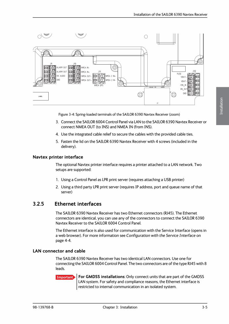
3. Connect the SAILOR 6004 Control Panel via LAN to the SAILOR 6390 Navtex Receiver or connect NMEA OUT (to INS) and NMEA IN (from INS).
4. Use the integrated cable relief to secure the cables with the provided cable ties.
5. Fasten the lid on the SAILOR 6390 Navtex Receiver with 4 screws (included in the delivery).
Navtex printer interface
The optional Navtex printer interface requires a printer attached to a LAN network. Two setups are supported:
1. Using a Control Panel as LPR print server (requires attaching a USB printer)
2. Using a third party LPR print server (requires IP address, port and queue name of that server)
3.2.5 Ethernet interfaces
The SAILOR 6390 Navtex Receiver has two Ethernet connectors (RJ45). The Ethernet connectors are identical, you can use any of the connectors to connect the SAILOR 6390 Navtex Receiver to the SAILOR 6004 Control Panel.
The Ethernet interface is also used for communication with the Service Interface (opens in a web browser). For more information see Configuration with the Service Interface on page 4-4.
LAN connector and cable
The SAILOR 6390 Navtex Receiver has two identical LAN connectors. Use one for connecting the SAILOR 6004 Control Panel. The two connectors are of the type RJ45 with 8 leads.
Figure 3-4: Spring-loaded terminals of the SAILOR 6390 Navtex Receiver (zoom)
LABELLABEL
J12J11
J10J9
C74C73 C64C63R1112
R1111R1110
J2
GND
FUSE
NMEA GPS
ALARM OUT NMEA IN-
NMEA IN+
NMEA OUT-
NMEA OUT+
ON_OUT
/ON_INVBAT-
VBAT+NMEA 2 IN-
NMEA 2 IN+RX AUDIO
GND
ALARM OUT
Important For GMDSS installations: Only connect units that are part of the GMDSS LAN system. For safety and compliance reasons, the Ethernet interface is restricted to internal communication in an isolated system.
Installation of the SAILOR 6004 Control panel
3-6 Chapter 3: Installation 98-139768-B
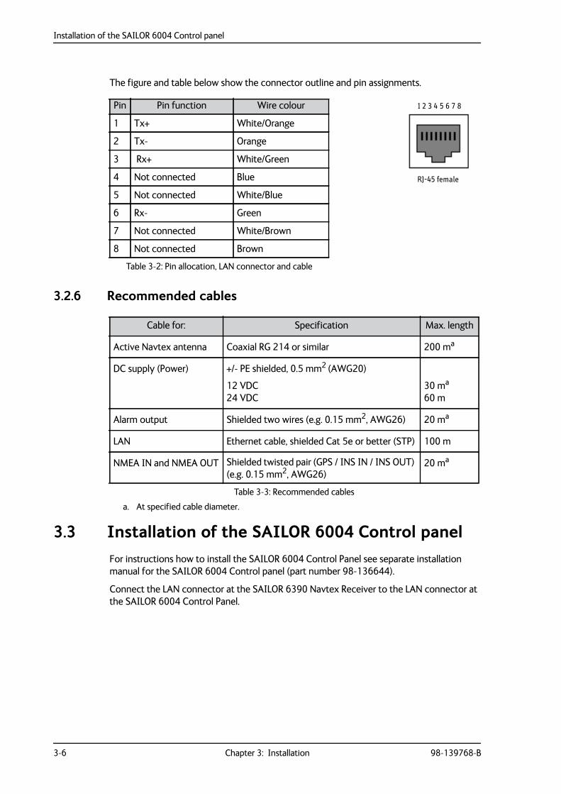
The figure and table below show the connector outline and pin assignments.
3.2.6 Recommended cables
3.3 Installation of the SAILOR 6004 Control panelFor instructions how to install the SAILOR 6004 Control Panel see separate installation manual for the SAILOR 6004 Control panel (part number 98-136644).
Connect the LAN connector at the SAILOR 6390 Navtex Receiver to the LAN connector at the SAILOR 6004 Control Panel.
Pin Pin function Wire colour
1 Tx+ White/Orange
2 Tx- Orange
3 Rx+ White/Green
4 Not connected Blue
5 Not connected White/Blue
6 Rx- Green
7 Not connected White/Brown
8 Not connected Brown
Table 3-2: Pin allocation, LAN connector and cable
RJ-45 female
1 2 3 4 5 6 7 8
Cable for: Specification Max. length
Active Navtex antenna Coaxial RG 214 or similar 200 ma
a. At specified cable diameter.
DC supply (Power) +/- PE shielded, 0.5 mm2 (AWG20)
12 VDC24 VDC
30 ma
60 m
Alarm output Shielded two wires (e.g. 0.15 mm2, AWG26) 20 ma
LAN Ethernet cable, shielded Cat 5e or better (STP) 100 m
NMEA IN and NMEA OUT Shielded twisted pair (GPS / INS IN / INS OUT) (e.g. 0.15 mm2, AWG26)
20 ma
Table 3-3: Recommended cables
98-139768-B 4-1
Chapter 44444
Conf
igur
atio
n
Configuration 4
This chapter has the following sections:
• Start up
• System and Navtex app installation
• Configuration with the Service Interface
• Verification
4.1 Start up
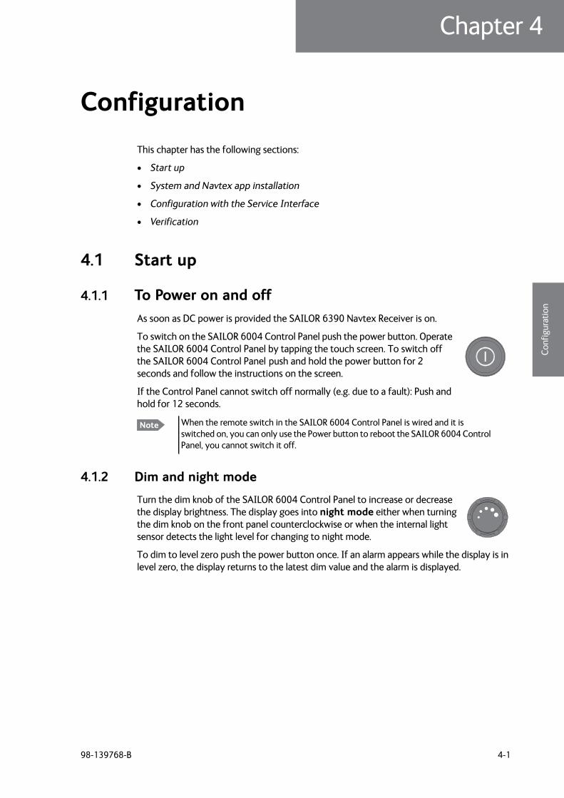
4.1.1 To Power on and offAs soon as DC power is provided the SAILOR 6390 Navtex Receiver is on.
To switch on the SAILOR 6004 Control Panel push the power button. Operate the SAILOR 6004 Control Panel by tapping the touch screen. To switch off the SAILOR 6004 Control Panel push and hold the power button for 2 seconds and follow the instructions on the screen.
If the Control Panel cannot switch off normally (e.g. due to a fault): Push and hold for 12 seconds.
4.1.2 Dim and night mode
Turn the dim knob of the SAILOR 6004 Control Panel to increase or decrease the display brightness. The display goes into night mode either when turning the dim knob on the front panel counterclockwise or when the internal light sensor detects the light level for changing to night mode.
To dim to level zero push the power button once. If an alarm appears while the display is in level zero, the display returns to the latest dim value and the alarm is displayed.
Note When the remote switch in the SAILOR 6004 Control Panel is wired and it is switched on, you can only use the Power button to reboot the SAILOR 6004 Control Panel, you cannot switch it off.
System and Navtex app installation
4-2 Chapter 4: Configuration 98-139768-B
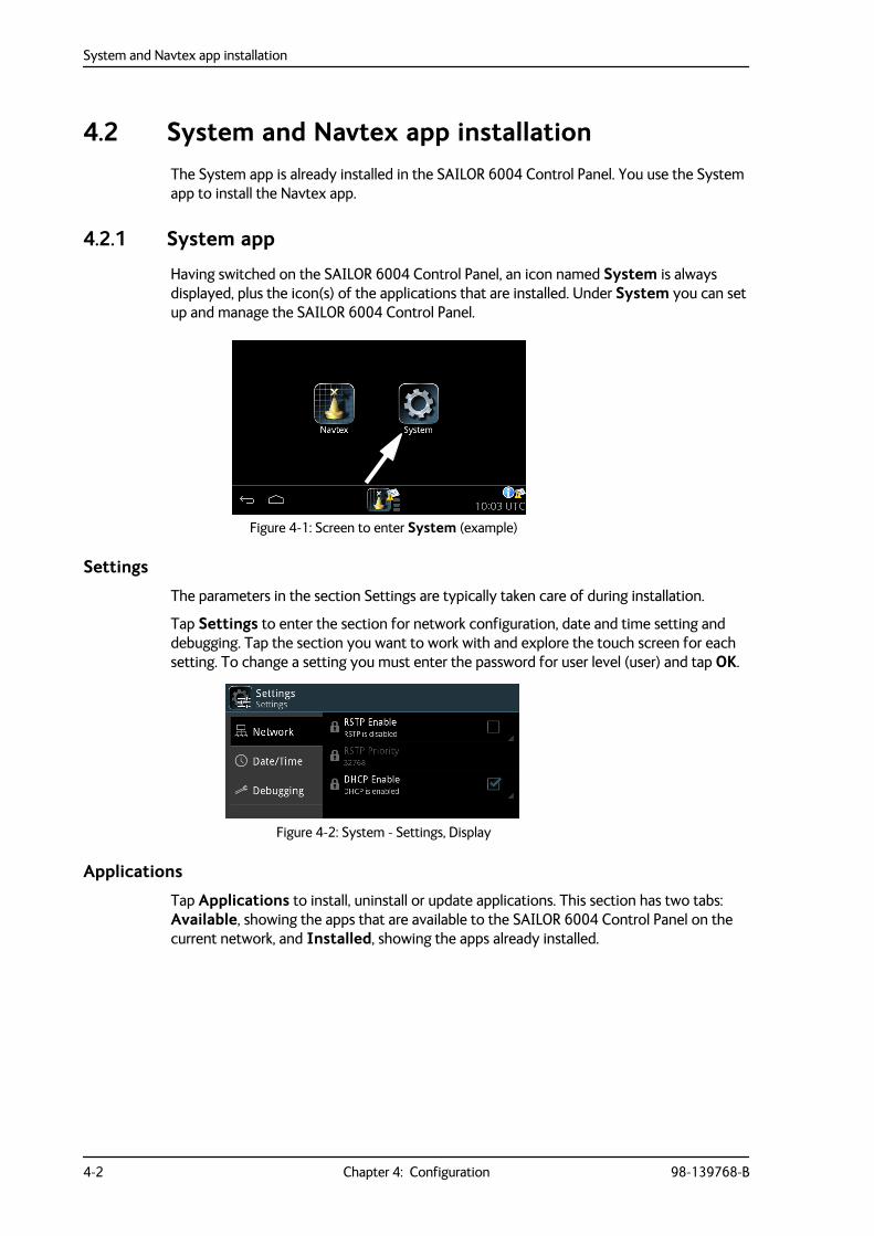
4.2 System and Navtex app installationThe System app is already installed in the SAILOR 6004 Control Panel. You use the System app to install the Navtex app.
4.2.1 System app
Having switched on the SAILOR 6004 Control Panel, an icon named System is always displayed, plus the icon(s) of the applications that are installed. Under System you can set up and manage the SAILOR 6004 Control Panel.
Settings
The parameters in the section Settings are typically taken care of during installation.
Tap Settings to enter the section for network configuration, date and time setting and debugging. Tap the section you want to work with and explore the touch screen for each setting. To change a setting you must enter the password for user level (user) and tap OK.
Applications
Tap Applications to install, uninstall or update applications. This section has two tabs: Available, showing the apps that are available to the SAILOR 6004 Control Panel on the current network, and Installed, showing the apps already installed.
Figure 4-1: Screen to enter System (example)
Figure 4-2: System - Settings, Display
System and Navtex app installation
98-139768-B Chapter 4: Configuration 4-3
4444
Conf
igur
atio
n
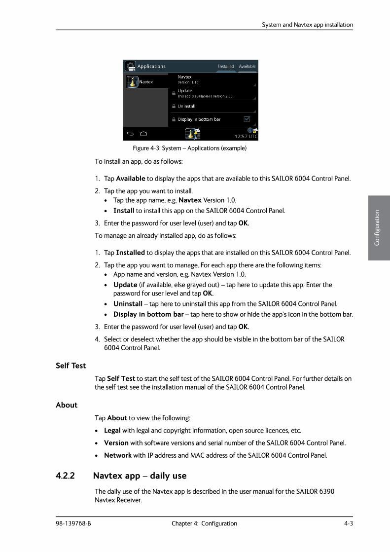
To install an app, do as follows:
1. Tap Available to display the apps that are available to this SAILOR 6004 Control Panel.
2. Tap the app you want to install.• Tap the app name, e.g. Navtex Version 1.0.• Install to install this app on the SAILOR 6004 Control Panel.
3. Enter the password for user level (user) and tap OK.
To manage an already installed app, do as follows:
1. Tap Installed to display the apps that are installed on this SAILOR 6004 Control Panel.
2. Tap the app you want to manage. For each app there are the following items:• App name and version, e.g. Navtex Version 1.0.• Update (if available, else grayed out) – tap here to update this app. Enter the
password for user level and tap OK.• Uninstall – tap here to uninstall this app from the SAILOR 6004 Control Panel. • Display in bottom bar – tap here to show or hide the app’s icon in the bottom bar.
3. Enter the password for user level (user) and tap OK.
4. Select or deselect whether the app should be visible in the bottom bar of the SAILOR 6004 Control Panel.
Self Test
Tap Self Test to start the self test of the SAILOR 6004 Control Panel. For further details on the self test see the installation manual of the SAILOR 6004 Control Panel.
About
Tap About to view the following:
• Legal with legal and copyright information, open source licences, etc.
• Version with software versions and serial number of the SAILOR 6004 Control Panel.
• Network with IP address and MAC address of the SAILOR 6004 Control Panel.
4.2.2 Navtex app – daily use
The daily use of the Navtex app is described in the user manual for the SAILOR 6390 Navtex Receiver.
Figure 4-3: System – Applications (example)
Configuration with the Service Interface
4-4 Chapter 4: Configuration 98-139768-B
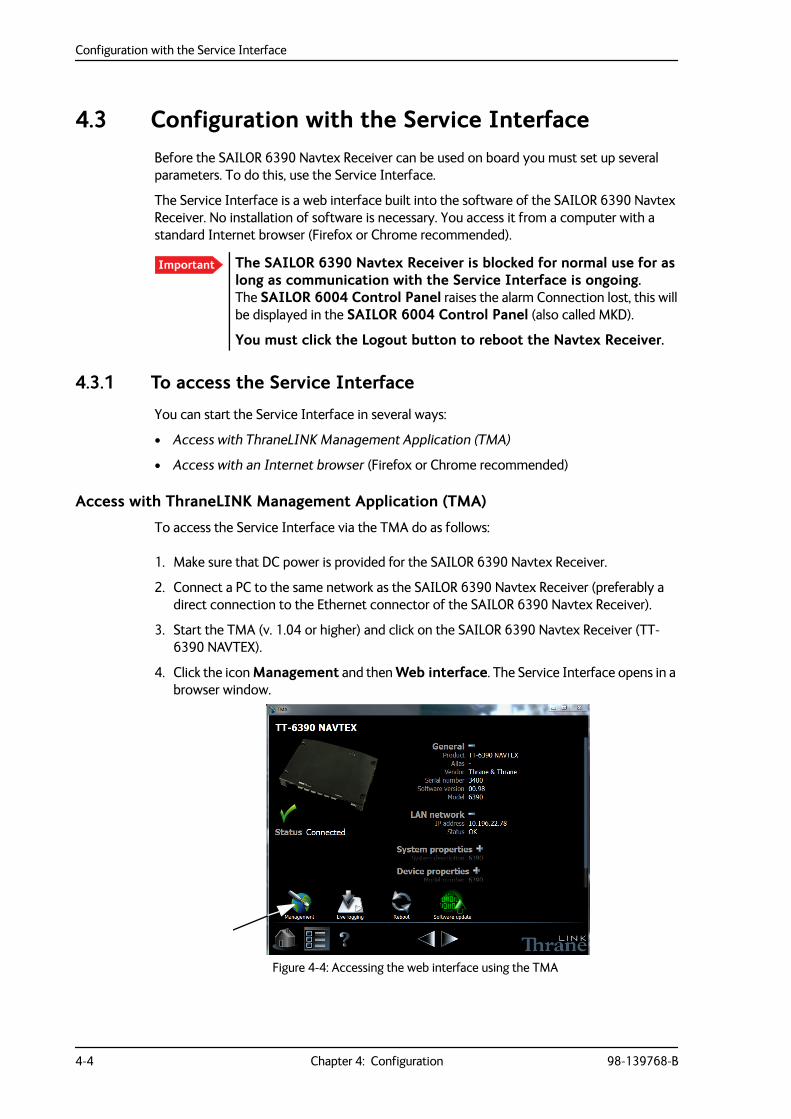
4.3 Configuration with the Service InterfaceBefore the SAILOR 6390 Navtex Receiver can be used on board you must set up several parameters. To do this, use the Service Interface.
The Service Interface is a web interface built into the software of the SAILOR 6390 Navtex Receiver. No installation of software is necessary. You access it from a computer with a standard Internet browser (Firefox or Chrome recommended).
4.3.1 To access the Service Interface
You can start the Service Interface in several ways:
• Access with ThraneLINK Management Application (TMA)
• Access with an Internet browser (Firefox or Chrome recommended)
Access with ThraneLINK Management Application (TMA)
To access the Service Interface via the TMA do as follows:
1. Make sure that DC power is provided for the SAILOR 6390 Navtex Receiver.
2. Connect a PC to the same network as the SAILOR 6390 Navtex Receiver (preferably a direct connection to the Ethernet connector of the SAILOR 6390 Navtex Receiver).
3. Start the TMA (v. 1.04 or higher) and click on the SAILOR 6390 Navtex Receiver (TT-6390 NAVTEX).
4. Click the icon Management and then Web interface. The Service Interface opens in a browser window.
Important The SAILOR 6390 Navtex Receiver is blocked for normal use for as long as communication with the Service Interface is ongoing. The SAILOR 6004 Control Panel raises the alarm Connection lost, this will be displayed in the SAILOR 6004 Control Panel (also called MKD).
You must click the Logout button to reboot the Navtex Receiver.
Figure 4-4: Accessing the web interface using the TMA
Configuration with the Service Interface
98-139768-B Chapter 4: Configuration 4-5
4444
Conf
igur
atio
n
Access with an Internet browser
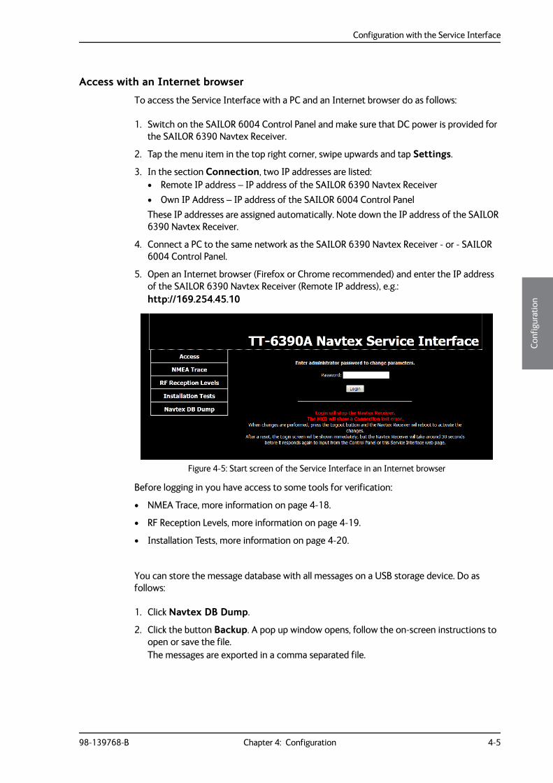
To access the Service Interface with a PC and an Internet browser do as follows:
1. Switch on the SAILOR 6004 Control Panel and make sure that DC power is provided for the SAILOR 6390 Navtex Receiver.
2. Tap the menu item in the top right corner, swipe upwards and tap Settings.
3. In the section Connection, two IP addresses are listed:• Remote IP address – IP address of the SAILOR 6390 Navtex Receiver• Own IP Address – IP address of the SAILOR 6004 Control PanelThese IP addresses are assigned automatically. Note down the IP address of the SAILOR 6390 Navtex Receiver.
4. Connect a PC to the same network as the SAILOR 6390 Navtex Receiver - or - SAILOR 6004 Control Panel.
5. Open an Internet browser (Firefox or Chrome recommended) and enter the IP address of the SAILOR 6390 Navtex Receiver (Remote IP address), e.g.:http://169.254.45.10
Before logging in you have access to some tools for verification:
• NMEA Trace, more information on page 4-18.
• RF Reception Levels, more information on page 4-19.
• Installation Tests, more information on page 4-20.
You can store the message database with all messages on a USB storage device. Do as follows:
1. Click Navtex DB Dump.
2. Click the button Backup. A pop up window opens, follow the on-screen instructions to open or save the file. The messages are exported in a comma separated file.
Figure 4-5: Start screen of the Service Interface in an Internet browser
Configuration with the Service Interface
4-6 Chapter 4: Configuration 98-139768-B
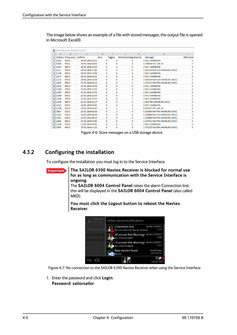
The image below shows an example of a file with stored messages, the output file is opened in Microsoft Excel®.
4.3.2 Configuring the installation
To configure the installation you must log in to the Service Interface.
1. Enter the password and click Login.Password: sailorsailor
Figure 4-6: Store messages on a USB storage device
Important The SAILOR 6390 Navtex Receiver is blocked for normal use for as long as communication with the Service Interface is ongoing. The SAILOR 6004 Control Panel raises the alarm Connection lost, this will be displayed in the SAILOR 6004 Control Panel (also called MKD).
You must click the Logout button to reboot the Navtex Receiver.
Figure 4-7: No connection to the SAILOR 6390 Navtex Receiver when using the Service Interface
Configuration with the Service Interface
98-139768-B Chapter 4: Configuration 4-7
4444
Conf
igur
atio
n
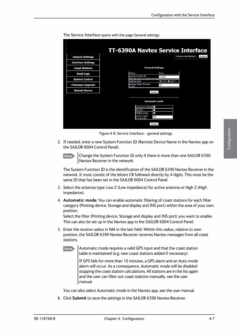
The Service Interface opens with the page General settings.
2. If needed, enter a new System Function ID (Remote Device Name in the Navtex app on the SAILOR 6004 Control Panel).
The System Function ID is the identification of the SAILOR 6390 Navtex Receiver in the network. It must consist of the letters CR followed directly by 4 digits. This must be the same ID that has been set in the SAILOR 6004 Control Panel.
3. Select the antenna type: Low Z (Low impedance) for active antenna or High Z (High impedance).
4. Automatic mode: You can enable automatic filtering of coast stations for each filter category (Printing device, Storage and display and INS port) within the area of your own position. Select the filter (Printing device, Storage and display and INS port) you want to enable.This can also be set up in the Navtex app in the SAILOR 6004 Control Panel.
5. Enter the receive radius in NM in the last field. Within this radius, relative to own position, the SAILOR 6390 Navtex Receiver receives Navtex messages from all coast stations.
You can also select Automatic mode in the Navtex app, see the user manual.
6. Click Submit to save the settings in the SAILOR 6390 Navtex Receiver.
Figure 4-8: Service Interface – general settings
Note Change the System Function ID only if there is more than one SAILOR 6390 Navtex Receiver in the network.
Note Automatic mode requires a valid GPS input and that the coast station table is maintained (e.g. new coast stations added if necessary).
If GPS fails for more than 10 minutes, a GPS alarm and an Auto mode alarm will occur. As a consequence, Automatic mode will be disabled stopping the coast station calculations. All stations are in the list again and the user can filter out coast stations manually, see the user manual.
Configuration with the Service Interface
4-8 Chapter 4: Configuration 98-139768-B
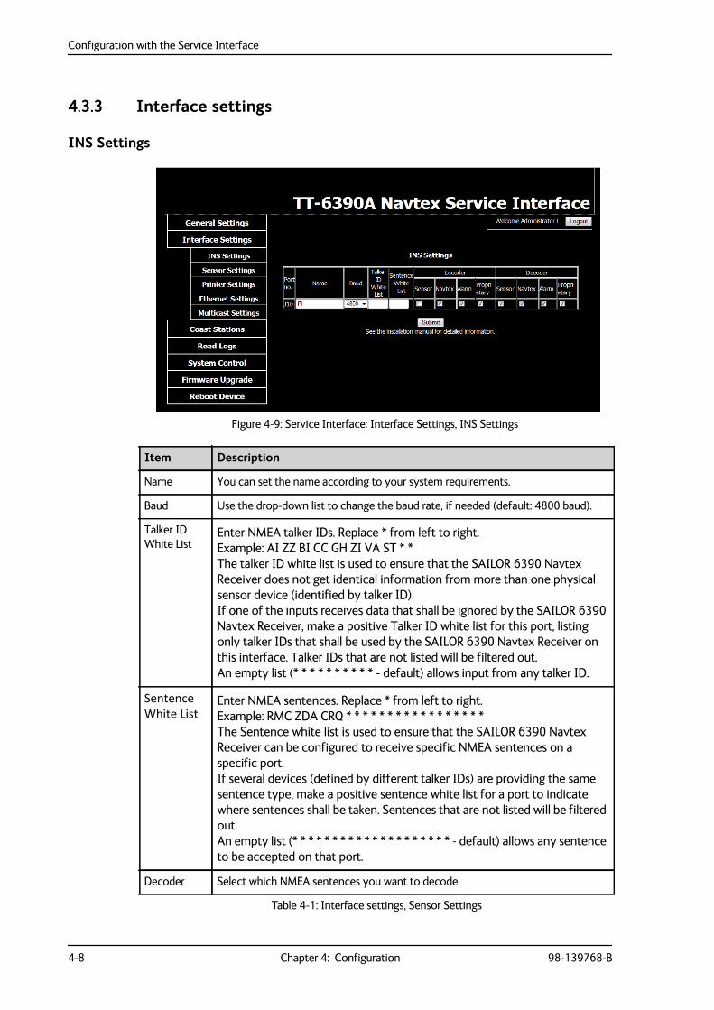
4.3.3 Interface settings
INS Settings
Figure 4-9: Service Interface: Interface Settings, INS Settings
Item Description
Name You can set the name according to your system requirements.
Baud Use the drop-down list to change the baud rate, if needed (default: 4800 baud).
Talker ID White List
Enter NMEA talker IDs. Replace * from left to right.Example: AI ZZ BI CC GH ZI VA ST * *The talker ID white list is used to ensure that the SAILOR 6390 Navtex Receiver does not get identical information from more than one physical sensor device (identified by talker ID).If one of the inputs receives data that shall be ignored by the SAILOR 6390 Navtex Receiver, make a positive Talker ID white list for this port, listing only talker IDs that shall be used by the SAILOR 6390 Navtex Receiver on this interface. Talker IDs that are not listed will be filtered out.An empty list (* * * * * * * * * * - default) allows input from any talker ID.
Sentence White List
Enter NMEA sentences. Replace * from left to right.Example: RMC ZDA CRQ * * * * * * * * * * * * * * * * *The Sentence white list is used to ensure that the SAILOR 6390 Navtex Receiver can be configured to receive specific NMEA sentences on a specific port.If several devices (defined by different talker IDs) are providing the same sentence type, make a positive sentence white list for a port to indicate where sentences shall be taken. Sentences that are not listed will be filtered out.An empty list (* * * * * * * * * * * * * * * * * * * * - default) allows any sentence to be accepted on that port.
Decoder Select which NMEA sentences you want to decode.
Table 4-1: Interface settings, Sensor Settings
Configuration with the Service Interface
98-139768-B Chapter 4: Configuration 4-9
4444
Conf
igur
atio
n
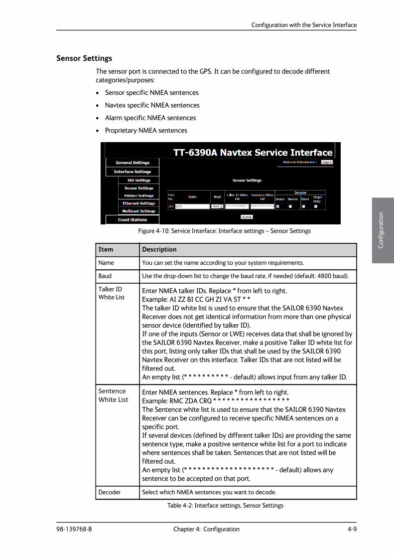
Sensor Settings
The sensor port is connected to the GPS. It can be configured to decode different categories/purposes:
• Sensor specific NMEA sentences
• Navtex specific NMEA sentences
• Alarm specific NMEA sentences
• Proprietary NMEA sentences
Figure 4-10: Service Interface: Interface settings – Sensor Settings
Item Description
Name You can set the name according to your system requirements.
Baud Use the drop-down list to change the baud rate, if needed (default: 4800 baud).
Talker ID White List
Enter NMEA talker IDs. Replace * from left to right.Example: AI ZZ BI CC GH ZI VA ST * *The talker ID white list is used to ensure that the SAILOR 6390 Navtex Receiver does not get identical information from more than one physical sensor device (identified by talker ID).If one of the inputs (Sensor or LWE) receives data that shall be ignored by the SAILOR 6390 Navtex Receiver, make a positive Talker ID white list for this port, listing only talker IDs that shall be used by the SAILOR 6390 Navtex Receiver on this interface. Talker IDs that are not listed will be filtered out.An empty list (* * * * * * * * * * - default) allows input from any talker ID.
Sentence White List
Enter NMEA sentences. Replace * from left to right.Example: RMC ZDA CRQ * * * * * * * * * * * * * * * * *The Sentence white list is used to ensure that the SAILOR 6390 Navtex Receiver can be configured to receive specific NMEA sentences on a specific port.If several devices (defined by different talker IDs) are providing the same sentence type, make a positive sentence white list for a port to indicate where sentences shall be taken. Sentences that are not listed will be filtered out.An empty list (* * * * * * * * * * * * * * * * * * * * - default) allows any sentence to be accepted on that port.
Decoder Select which NMEA sentences you want to decode.
Table 4-2: Interface settings, Sensor Settings
Configuration with the Service Interface
4-10 Chapter 4: Configuration 98-139768-B
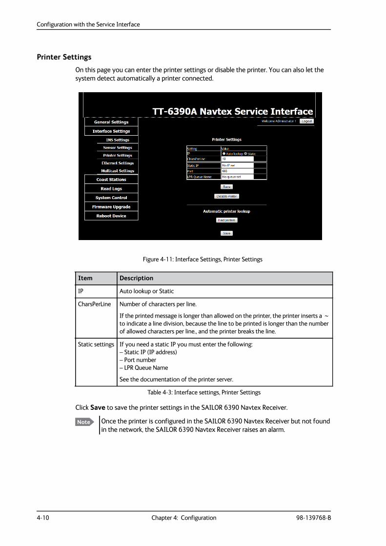
Printer Settings
On this page you can enter the printer settings or disable the printer. You can also let the system detect automatically a printer connected.
Click Save to save the printer settings in the SAILOR 6390 Navtex Receiver.
Figure 4-11: Interface Settings, Printer Settings
Item Description
IP Auto lookup or Static
CharsPerLine Number of characters per line.
If the printed message is longer than allowed on the printer, the printer inserts a to indicate a line division, because the line to be printed is longer than the number of allowed characters per line., and the printer breaks the line.
Static settings If you need a static IP you must enter the following:– Static IP (IP address)– Port number– LPR Queue Name
See the documentation of the printer server.
Table 4-3: Interface settings, Printer Settings
Note Once the printer is configured in the SAILOR 6390 Navtex Receiver but not found in the network, the SAILOR 6390 Navtex Receiver raises an alarm.
Configuration with the Service Interface
98-139768-B Chapter 4: Configuration 4-11
4444
Conf
igur
atio
n
Use scenario 1: Printer and ThraneLINK compatible print server
To set up a printer that is compatible with a ThraneLINK print server, e.g. the SAILOR 6004 Control Panel, do as follows:
1. Connect the printer to one of the two USB ports of the SAILOR 6004 Control Panel.
2. Switch on the SAILOR 6004 Control Panel and the printer attached.
3. Click Find printers in the section Automatic printer lookup. Then a list with serial numbers of the available ThraneLINK print servers with attached printers is displayed.
4. Click the serial number of the desired print server, e.g. a serial number of a SAILOR 6004 Control Panel.
5. Click Save to save the printer settings in the SAILOR 6390 Navtex Receiver.
Use scenario 2: 3rd party printer
To set up a 3rd party printer do as follows:
1. At Setting, IP select Static.
2. Fill in the Static IP (IP address), Port number and LPR Queue Name. See the documentation of the printer server
3. Click Save save the printer settings in the SAILOR 6390 Navtex Receiver.
Use scenario 3: Disable printer
Click Disable Printer if you do not intend to install a printer for printing Navtex messages. Then the SAILOR 6390 Navtex Receiver will not give printer alarms.
Ethernet Settings
The SAILOR 6390 Navtex Receiver and the SAILOR 6004 Control Panel communicate through Ethernet. Other equipment can also communicate using the same Ethernet. Therefore, it is necessary to configure an IP address and network ID for the SAILOR 6390 Navtex Receiver in the SAILOR 6004 Control Panel. I.e. the two devices must be paired.
The IP addresses of the SAILOR 6390 Navtex Receiver and the SAILOR 6004 Control Panel are acquired automatically. There is also the possibility to set a static IP address. The IP addresses are unique for each device connected to the Ethernet network.
There are two network IDs, one for the SAILOR 6390 Navtex Receiver and one for the SAILOR 6004 Control Panel. The ID for Navtex receivers consists of two letters (CR or NR)
Configuration with the Service Interface
4-12 Chapter 4: Configuration 98-139768-B
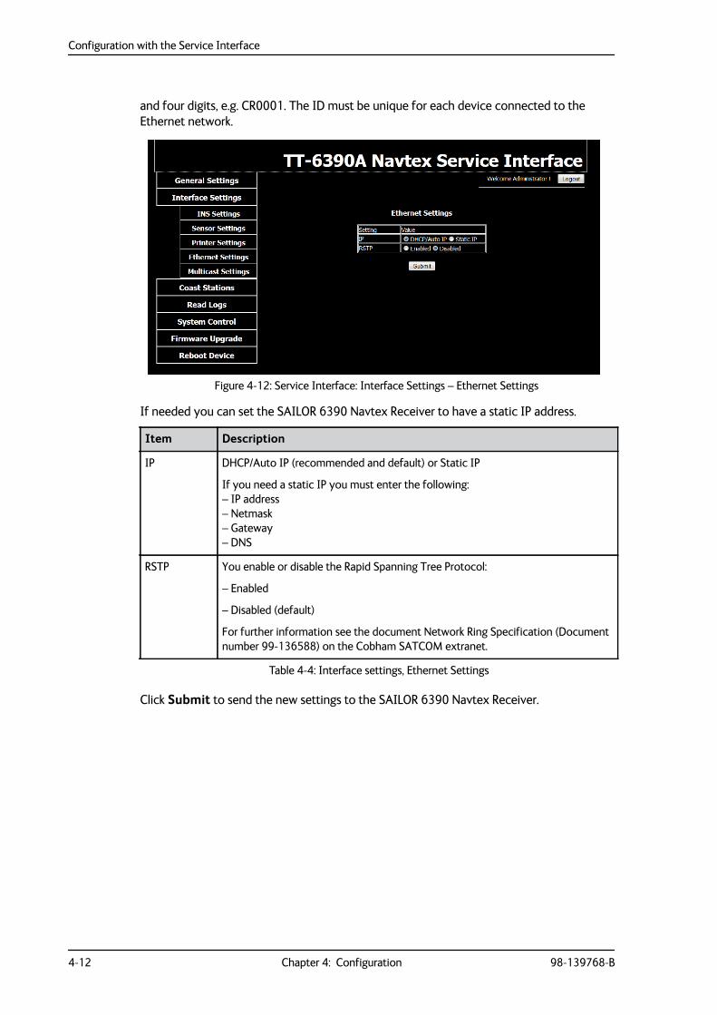
and four digits, e.g. CR0001. The ID must be unique for each device connected to the Ethernet network.
If needed you can set the SAILOR 6390 Navtex Receiver to have a static IP address.
Click Submit to send the new settings to the SAILOR 6390 Navtex Receiver.
Figure 4-12: Service Interface: Interface Settings – Ethernet Settings
Item Description
IP DHCP/Auto IP (recommended and default) or Static IP
If you need a static IP you must enter the following:– IP address– Netmask– Gateway– DNS
RSTP You enable or disable the Rapid Spanning Tree Protocol:
– Enabled
– Disabled (default)
For further information see the document Network Ring Specification (Document number 99-136588) on the Cobham SATCOM extranet.
Table 4-4: Interface settings, Ethernet Settings
Configuration with the Service Interface
98-139768-B Chapter 4: Configuration 4-13
4444
Conf
igur
atio
n
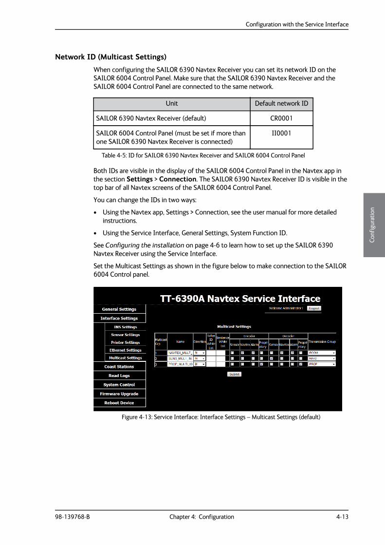
Network ID (Multicast Settings)
When configuring the SAILOR 6390 Navtex Receiver you can set its network ID on the SAILOR 6004 Control Panel. Make sure that the SAILOR 6390 Navtex Receiver and the SAILOR 6004 Control Panel are connected to the same network.
Both IDs are visible in the display of the SAILOR 6004 Control Panel in the Navtex app in the section Settings > Connection. The SAILOR 6390 Navtex Receiver ID is visible in the top bar of all Navtex screens of the SAILOR 6004 Control Panel.
You can change the IDs in two ways:
• Using the Navtex app, Settings > Connection, see the user manual for more detailed instructions.
• Using the Service Interface, General Settings, System Function ID.
See Configuring the installation on page 4-6 to learn how to set up the SAILOR 6390 Navtex Receiver using the Service Interface.
Set the Multicast Settings as shown in the figure below to make connection to the SAILOR 6004 Control panel.
Unit Default network ID
SAILOR 6390 Navtex Receiver (default) CR0001
SAILOR 6004 Control Panel (must be set if more than one SAILOR 6390 Navtex Receiver is connected)
II0001
Table 4-5: ID for SAILOR 6390 Navtex Receiver and SAILOR 6004 Control Panel
Figure 4-13: Service Interface: Interface Settings – Multicast Settings (default)
Configuration with the Service Interface
4-14 Chapter 4: Configuration 98-139768-B
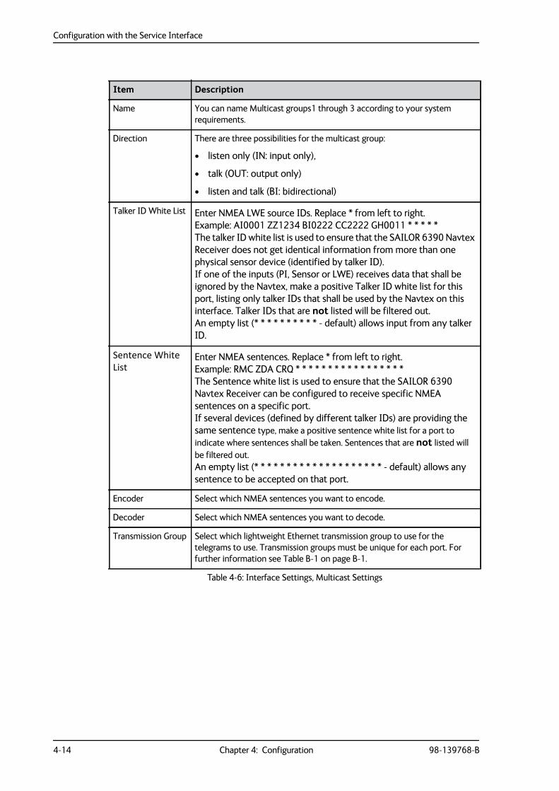
Item Description
Name You can name Multicast groups1 through 3 according to your system requirements.
Direction There are three possibilities for the multicast group:
• listen only (IN: input only),
• talk (OUT: output only)
• listen and talk (BI: bidirectional)
Talker ID White List Enter NMEA LWE source IDs. Replace * from left to right.Example: AI0001 ZZ1234 BI0222 CC2222 GH0011 * * * * *The talker ID white list is used to ensure that the SAILOR 6390 Navtex Receiver does not get identical information from more than one physical sensor device (identified by talker ID).If one of the inputs (PI, Sensor or LWE) receives data that shall be ignored by the Navtex, make a positive Talker ID white list for this port, listing only talker IDs that shall be used by the Navtex on this interface. Talker IDs that are not listed will be filtered out.An empty list (* * * * * * * * * * - default) allows input from any talker ID.
Sentence White List
Enter NMEA sentences. Replace * from left to right.Example: RMC ZDA CRQ * * * * * * * * * * * * * * * * *The Sentence white list is used to ensure that the SAILOR 6390 Navtex Receiver can be configured to receive specific NMEA sentences on a specific port.If several devices (defined by different talker IDs) are providing the same sentence type, make a positive sentence white list for a port to indicate where sentences shall be taken. Sentences that are not listed will be filtered out.An empty list (* * * * * * * * * * * * * * * * * * * * - default) allows any sentence to be accepted on that port.
Encoder Select which NMEA sentences you want to encode.
Decoder Select which NMEA sentences you want to decode.
Transmission Group Select which lightweight Ethernet transmission group to use for the telegrams to use. Transmission groups must be unique for each port. For further information see Table B-1 on page B-1.
Table 4-6: Interface Settings, Multicast Settings
Configuration with the Service Interface
98-139768-B Chapter 4: Configuration 4-15
4444
Conf
igur
atio
n
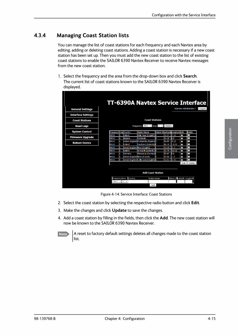
4.3.4 Managing Coast Station lists
You can manage the list of coast stations for each frequency and each Navtex area by editing, adding or deleting coast stations. Adding a coast station is necessary if a new coast station has been set up. Then you must add the new coast station to the list of existing coast stations to enable the SAILOR 6390 Navtex Receiver to receive Navtex messages from the new coast station.
1. Select the frequency and the area from the drop-down box and click Search. The current list of coast stations known to the SAILOR 6390 Navtex Receiver is displayed.
2. Select the coast station by selecting the respective radio button and click Edit.
3. Make the changes and click Update to save the changes.
4. Add a coast station by filling in the fields, then click the Add. The new coast station will now be known to the SAILOR 6390 Navtex Receiver.
Figure 4-14: Service Interface: Coast Stations
Note A reset to factory default settings deletes all changes made to the coast station list.
Configuration with the Service Interface
4-16 Chapter 4: Configuration 98-139768-B
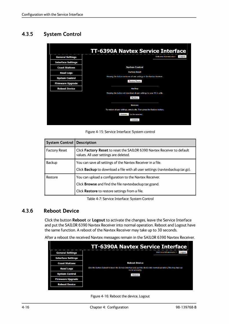
4.3.5 System Control
4.3.6 Reboot Device
Click the button Reboot or Logout to activate the changes, leave the Service Interface and put the SAILOR 6390 Navtex Receiver into normal operation. Reboot and Logout have the same function. A reboot of the Navtex Receiver may take up to 30 seconds.
After a reboot the received Navtex messages remain in the SAILOR 6390 Navtex Receiver.
Figure 4-15: Service Interface: System control
System Control Description
Factory Reset Click Factory Reset to reset the SAILOR 6390 Navtex Receiver to default values. All user settings are deleted.
Backup You can save all settings of the Navtex Receiver in a file.
Click Backup to download a file with all user settings (navtexbackup.tar.gz).
Restore You can upload a configuration to the Navtex Receiver.
Click Browse and find the file navtexbackup.tar.gzand.
Click Restore to restore settings from a file.
Table 4-7: Service Interface: System Control
Figure 4-16: Reboot the device, Logout
Verification
98-139768-B Chapter 4: Configuration 4-17
4444
Conf
igur
atio
n
4.4 VerificationThe following sections provide a check list for verifying the installation and some tools for verification:
• NMEA Trace tool
• Checking RF Reception Levels
• Installation Tests
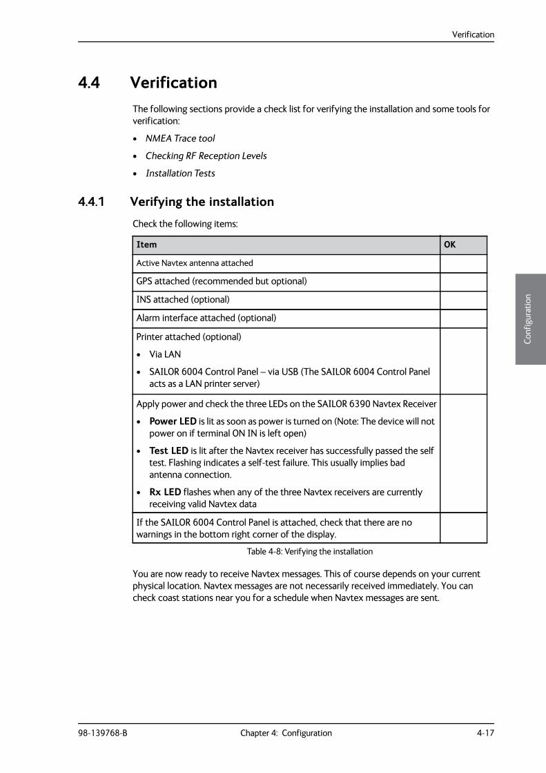
4.4.1 Verifying the installation
Check the following items:
You are now ready to receive Navtex messages. This of course depends on your current physical location. Navtex messages are not necessarily received immediately. You can check coast stations near you for a schedule when Navtex messages are sent.
Item OK
Active Navtex antenna attached
GPS attached (recommended but optional)
INS attached (optional)
Alarm interface attached (optional)
Printer attached (optional)
• Via LAN
• SAILOR 6004 Control Panel – via USB (The SAILOR 6004 Control Panel acts as a LAN printer server)
Apply power and check the three LEDs on the SAILOR 6390 Navtex Receiver
• Power LED is lit as soon as power is turned on (Note: The device will not power on if terminal ON IN is left open)
• Test LED is lit after the Navtex receiver has successfully passed the self test. Flashing indicates a self-test failure. This usually implies bad antenna connection.
• Rx LED flashes when any of the three Navtex receivers are currently receiving valid Navtex data
If the SAILOR 6004 Control Panel is attached, check that there are no warnings in the bottom right corner of the display.
Table 4-8: Verifying the installation
Verification
4-18 Chapter 4: Configuration 98-139768-B
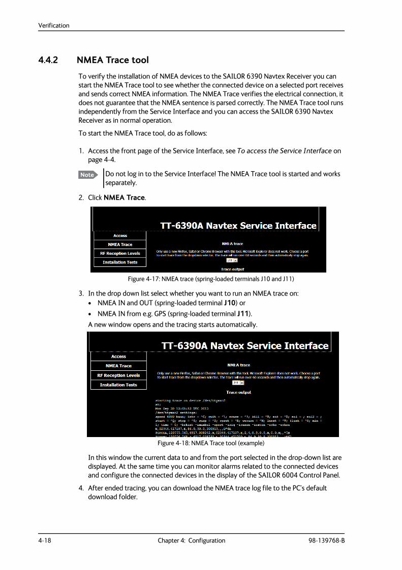
4.4.2 NMEA Trace tool
To verify the installation of NMEA devices to the SAILOR 6390 Navtex Receiver you can start the NMEA Trace tool to see whether the connected device on a selected port receives and sends correct NMEA information. The NMEA Trace verifies the electrical connection, it does not guarantee that the NMEA sentence is parsed correctly. The NMEA Trace tool runs independently from the Service Interface and you can access the SAILOR 6390 Navtex Receiver as in normal operation.
To start the NMEA Trace tool, do as follows:
1. Access the front page of the Service Interface, see To access the Service Interface on page 4-4.
2. Click NMEA Trace.
3. In the drop down list select whether you want to run an NMEA trace on:• NMEA IN and OUT (spring-loaded terminal J10) or • NMEA IN from e.g. GPS (spring-loaded terminal J11). A new window opens and the tracing starts automatically.
In this window the current data to and from the port selected in the drop-down list are displayed. At the same time you can monitor alarms related to the connected devices and configure the connected devices in the display of the SAILOR 6004 Control Panel.
4. After ended tracing, you can download the NMEA trace log file to the PC’s default download folder.
Note Do not log in to the Service Interface! The NMEA Trace tool is started and works separately.
Figure 4-17: NMEA trace (spring-loaded terminals J10 and J11)
Figure 4-18: NMEA Trace tool (example)
Verification
98-139768-B Chapter 4: Configuration 4-19
4444
Conf
igur
atio
n
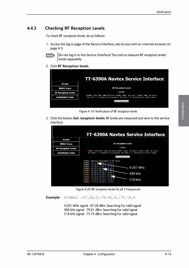
4.4.3 Checking RF Reception Levels
To check RF reception levels, do as follows:
1. Access the log-in page of the Service Interface, see Access with an Internet browser on page 4-5.
2. Click RF Reception levels.
3. Click the button Get reception levels. RF levels are measured and sent to the service interface.
Example: SIGNAL: -67.28,0,-79.91,0,-75.75,0
4.201 MHz signal: -67.28 dBm, Searching for valid signal490 kHz signal: -79.91 dBm, Searching for valid signal518 kHz signal: -75.75 dBm, Searching for valid signal
Note Do not log in to the Service Interface! The tool to measure RF reception levels works separately.
Figure 4-19: Verification of RF reception levels
Figure 4-20: RF reception levels for all 3 frequencies
4.201 MHz
490 kHz
518 kHz
Verification
4-20 Chapter 4: Configuration 98-139768-B
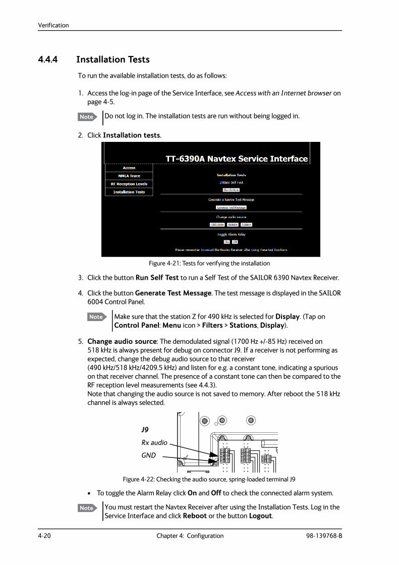
4.4.4 Installation Tests
To run the available installation tests, do as follows:
1. Access the log-in page of the Service Interface, see Access with an Internet browser on page 4-5.
2. Click Installation tests.
3. Click the button Run Self Test to run a Self Test of the SAILOR 6390 Navtex Receiver.
4. Click the button Generate Test Message. The test message is displayed in the SAILOR 6004 Control Panel.
5. Change audio source: The demodulated signal (1700 Hz +/-85 Hz) received on 518 kHz is always present for debug on connector J9. If a receiver is not performing as expected, change the debug audio source to that receiver (490 kHz/518 kHz/4209.5 kHz) and listen for e.g. a constant tone, indicating a spurious on that receiver channel. The presence of a constant tone can then be compared to the RF reception level measurements (see 4.4.3).Note that changing the audio source is not saved to memory. After reboot the 518 kHz channel is always selected.
• To toggle the Alarm Relay click On and Off to check the connected alarm system.
Note Do not log in. The installation tests are run without being logged in.
Figure 4-21: Tests for verifying the installation
Note Make sure that the station Z for 490 kHz is selected for Display. (Tap on Control Panel: Menu icon > Filters > Stations, Display).
Figure 4-22: Checking the audio source, spring-loaded terminal J9
Note You must restart the Navtex Receiver after using the Installation Tests. Log in the Service Interface and click Reboot or the button Logout.
J9
Rx audio
GND
98-139768-B 5-1
Chapter 55555
Serv
ice
& m
aint
enan
ce
Service & maintenance 5
This chapter has the following sections:
• Maintenance
• Alarms and notifications
• Troubleshooting guide
• Warranty and returning units for repair
5.1 MaintenanceMaintenance of the SAILOR 6390 Navtex Receiver can be reduced to a maintenance check at each visit of the service staff. Inspect the unit for mechanical damages, salt deposits, corrosion and any foreign material. Due to its robust construction and ruggedness the unit has a long lifetime. Anyway it must carefully be checked at intervals not longer than 12 months – dependent on the current working conditions.
Contact for support
Contact an authorized dealer for technical service and support of the SAILOR 6390 Navtex Receiver. Before contacting the authorized dealer you can go through the troubleshooting guide to solve some of the most common operational problems.
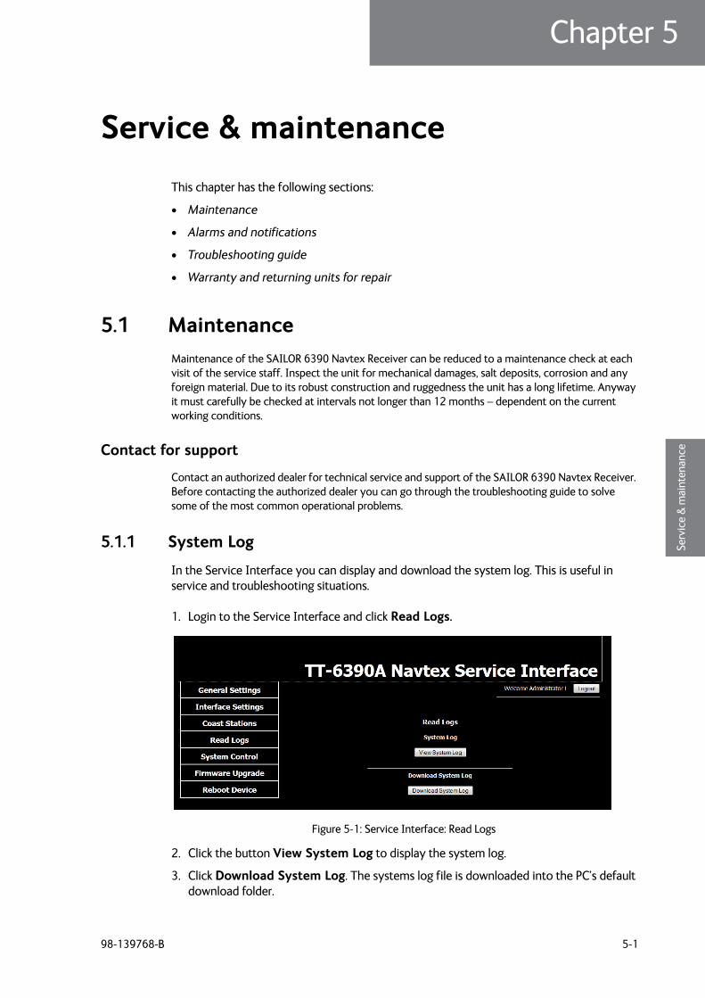
5.1.1 System Log
In the Service Interface you can display and download the system log. This is useful in service and troubleshooting situations.
1. Login to the Service Interface and click Read Logs.
2. Click the button View System Log to display the system log.
3. Click Download System Log. The systems log file is downloaded into the PC’s default download folder.
Figure 5-1: Service Interface: Read Logs
Maintenance
5-2 Chapter 5: Service & maintenance 98-139768-B
5.1.2 Software update
You can update the SAILOR 6390 Navtex Receiver software in the following ways:
• Software update using the Navtex app
• Software update with the TMA (ThraneLINK Management Application)
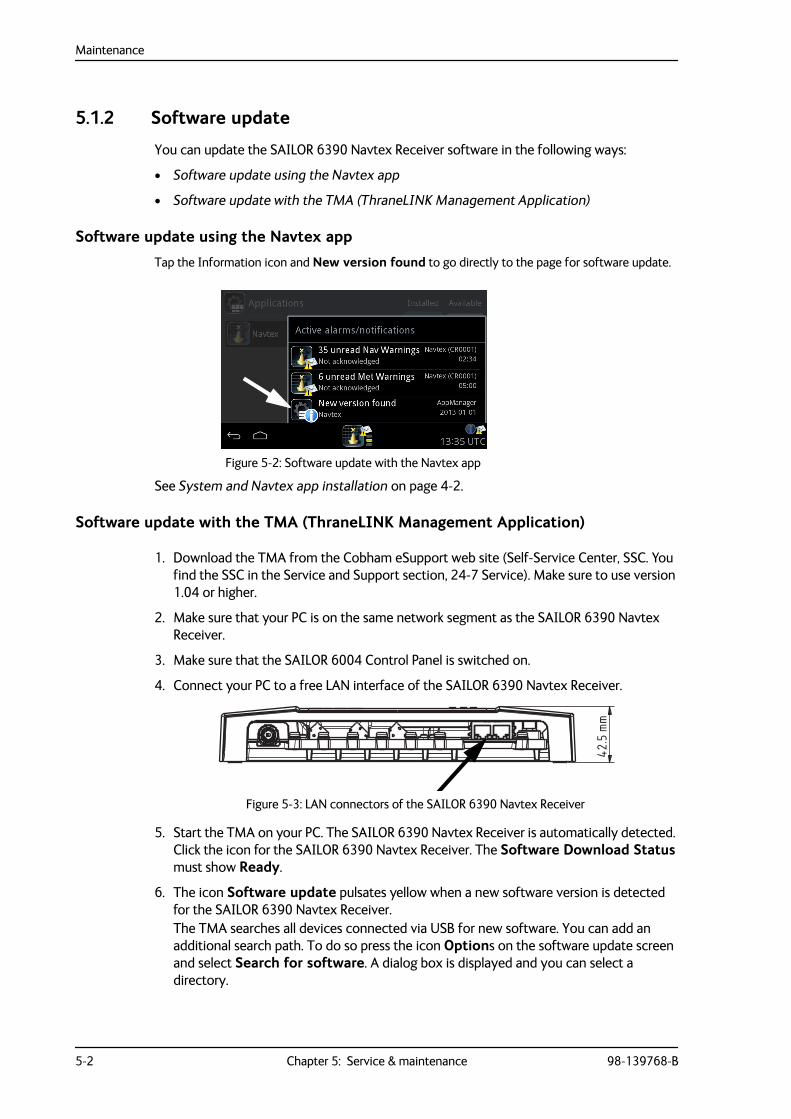
Software update using the Navtex appTap the Information icon and New version found to go directly to the page for software update.
See System and Navtex app installation on page 4-2.
Software update with the TMA (ThraneLINK Management Application)
1. Download the TMA from the Cobham eSupport web site (Self-Service Center, SSC. You find the SSC in the Service and Support section, 24-7 Service). Make sure to use version 1.04 or higher.
2. Make sure that your PC is on the same network segment as the SAILOR 6390 Navtex Receiver.
3. Make sure that the SAILOR 6004 Control Panel is switched on.
4. Connect your PC to a free LAN interface of the SAILOR 6390 Navtex Receiver.
5. Start the TMA on your PC. The SAILOR 6390 Navtex Receiver is automatically detected. Click the icon for the SAILOR 6390 Navtex Receiver. The Software Download Status must show Ready.
6. The icon Software update pulsates yellow when a new software version is detected for the SAILOR 6390 Navtex Receiver.The TMA searches all devices connected via USB for new software. You can add an additional search path. To do so press the icon Options on the software update screen and select Search for software. A dialog box is displayed and you can select a directory.
Figure 5-2: Software update with the Navtex app
Figure 5-3: LAN connectors of the SAILOR 6390 Navtex Receiver
42.5
mm
Maintenance
98-139768-B Chapter 5: Service & maintenance 5-3
5555
Serv
ice
& m
aint
enan
ce
7. To start the software update click the icon Software update and select Update. The current and the new software version numbers are displayed.You can also select a specific software version. To do so press the icon Options on the software update screen and select Select software. A list of available software versions is displayed. Select one and click the button Update.
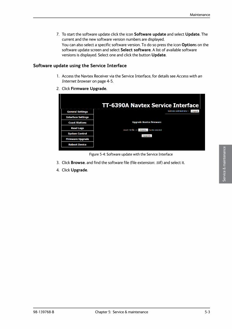
Software update using the Service Interface
1. Access the Navtex Receiver via the Service Interface, for details see Access with an Internet browser on page 4-5.
2. Click Firmware Upgrade.
3. Click Browse. and find the software file (file extension: .tiif) and select it.
4. Click Upgrade.
Figure 5-4: Software update with the Service Interface
Maintenance
5-4 Chapter 5: Service & maintenance 98-139768-B
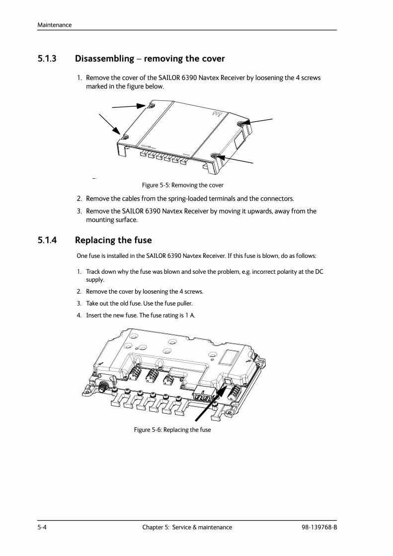
5.1.3 Disassembling – removing the cover
1. Remove the cover of the SAILOR 6390 Navtex Receiver by loosening the 4 screws marked in the figure below.
2. Remove the cables from the spring-loaded terminals and the connectors.
3. Remove the SAILOR 6390 Navtex Receiver by moving it upwards, away from the mounting surface.
5.1.4 Replacing the fuse
One fuse is installed in the SAILOR 6390 Navtex Receiver. If this fuse is blown, do as follows:
1. Track down why the fuse was blown and solve the problem, e.g. incorrect polarity at the DC supply.
2. Remove the cover by loosening the 4 screws.
3. Take out the old fuse. Use the fuse puller.
4. Insert the new fuse. The fuse rating is 1 A.
Figure 5-5: Removing the cover
Figure 5-6: Replacing the fuse
Alarms and notifications
98-139768-B Chapter 5: Service & maintenance 5-5
5555
Serv
ice
& m
aint
enan
ce
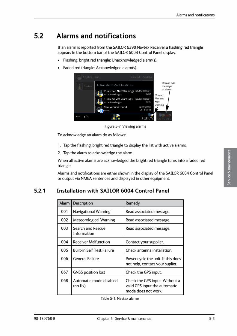
5.2 Alarms and notificationsIf an alarm is reported from the SAILOR 6390 Navtex Receiver a flashing red triangle appears in the bottom bar of the SAILOR 6004 Control Panel display:
• Flashing, bright red triangle: Unacknowledged alarm(s).
• Faded red triangle: Acknowledged alarm(s).
To acknowledge an alarm do as follows:
1. Tap the flashing, bright red triangle to display the list with active alarms.
2. Tap the alarm to acknowledge the alarm.
When all active alarms are acknowledged the bright red triangle turns into a faded red triangle.
Alarms and notifications are either shown in the display of the SAILOR 6004 Control Panel or output via NMEA sentences and displayed in other equipment.
5.2.1 Installation with SAILOR 6004 Control Panel
Figure 5-7: Viewing alarms
Unread SAR message or alarm
Unread Nav and Met warning
Alarm Description Remedy
001 Navigational Warning Read associated message.
002 Meteorological Warning Read associated message.
003 Search and Rescue Information
Read associated message.
004 Receiver Malfunction Contact your supplier.
005 Built-in Self Test Failure Check antenna installation.
006 General Failure Power cycle the unit. If this does not help, contact your suplier.
067 GNSS position lost Check the GPS input.
068 Automatic mode disabled (no fix)
Check the GPS input. Without a valid GPS input the automatic mode does not work.
Table 5-1: Navtex alarms
Alarms and notifications
5-6 Chapter 5: Service & maintenance 98-139768-B
If the connection between the SAILOR 6390 Navtex Receiver and the SAILOR 6004 Control Panel is lost, the SAILOR 6004 Control Panel shows an error “Connection lost”. Make sure that no one is connected to the SAILOR 6390 Navtex Receiver using the Service Interface.
5.2.2 Installation with an INS
Alarms and notifications are signalled via the NMEA sentence ALR. See the user documentation of the equipment connected to the SAILOR 6390 Navtex Receiver for further information on how alarms and notifications are displayed.
Example: $CRALR,246060,002,A,V,NAVTEX: Meteorological Warning*09
CR = NavtexALR = alarm sentence246060 = time (hours,minutes, seconds)1
002 = alarm number (see Table 5-1 on page 5 and Table 5-2 on page 6)A (A – active / V – not active)V (A – confirmed / V – not confirmed)NAVTEX: Meteorological Warning (text description)*09 (checksum indicator and checksum)
Alarm Description Remedy
060 Printer is offline Set online.
061 Printer is busy Wait until current print job is finished.
062 Printer is low on paper
Insert more paper.
063 Printer is out of paper Insert more paper.
064 Printer not connected
Check the printer connection.a
a. Alarm 064 is the only alarm output for 3rd party print servers.
065 Printer error See the original printer documentation.
066 No default printer configured
This must be set up during installation. Contact your installation centre.
Table 5-2: Navtex alarms, printer
1. 246060 indicates unknown time (invalid time stamp), e.g. if there is no or invalid GPS input.
Troubleshooting guide
98-139768-B Chapter 5: Service & maintenance 5-7
5555
Serv
ice
& m
aint
enan
ce
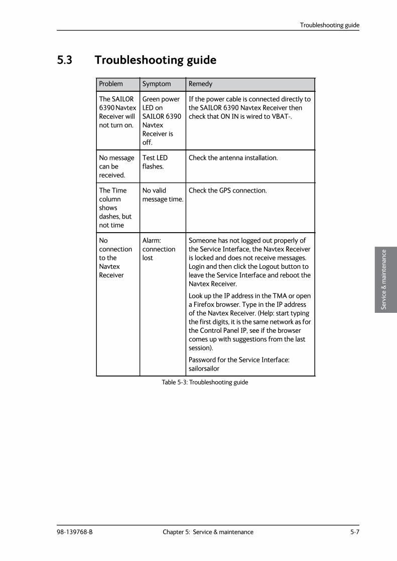
5.3 Troubleshooting guide
Problem Symptom Remedy
The SAILOR 6390 Navtex Receiver will not turn on.
Green power LED on SAILOR 6390 Navtex Receiver is off.
If the power cable is connected directly to the SAILOR 6390 Navtex Receiver then check that ON IN is wired to VBAT-.
No message can be received.
Test LED flashes.
Check the antenna installation.
The Time column shows dashes, but not time
No valid message time.
Check the GPS connection.
No connection to the Navtex Receiver
Alarm: connection lost
Someone has not logged out properly of the Service Interface, the Navtex Receiver is locked and does not receive messages. Login and then click the Logout button to leave the Service Interface and reboot the Navtex Receiver.
Look up the IP address in the TMA or open a Firefox browser. Type in the IP address of the Navtex Receiver. (Help: start typing the first digits, it is the same network as for the Control Panel IP, see if the browser comes up with suggestions from the last session).
Password for the Service Interface: sailorsailor
Table 5-3: Troubleshooting guide
Troubleshooting guide
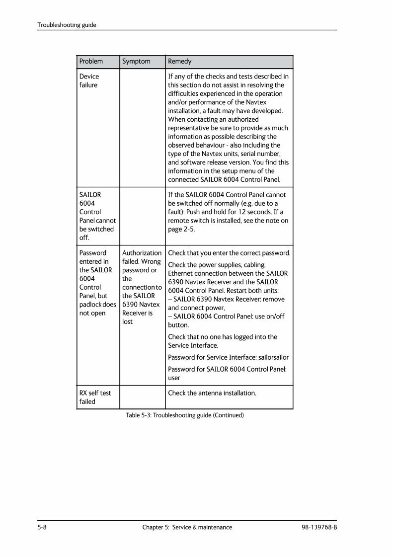
5-8 Chapter 5: Service & maintenance 98-139768-B
Device failure
If any of the checks and tests described in this section do not assist in resolving the difficulties experienced in the operation and/or performance of the Navtex installation, a fault may have developed. When contacting an authorized representative be sure to provide as much information as possible describing the observed behaviour - also including the type of the Navtex units, serial number, and software release version. You find this information in the setup menu of the connected SAILOR 6004 Control Panel.
SAILOR 6004 Control Panel cannot be switched off.
If the SAILOR 6004 Control Panel cannot be switched off normally (e.g. due to a fault): Push and hold for 12 seconds. If a remote switch is installed, see the note on page 2-5.
Password entered in the SAILOR 6004 Control Panel, but padlock does not open
Authorization failed. Wrong password or the connection to the SAILOR 6390 Navtex Receiver is lost
Check that you enter the correct password.
Check the power supplies, cabling, Ethernet connection between the SAILOR 6390 Navtex Receiver and the SAILOR 6004 Control Panel. Restart both units: – SAILOR 6390 Navtex Receiver: remove and connect power, – SAILOR 6004 Control Panel: use on/off button.
Check that no one has logged into the Service Interface.
Password for Service Interface: sailorsailor
Password for SAILOR 6004 Control Panel: user
RX self test failed
Check the antenna installation.
Problem Symptom Remedy
Table 5-3: Troubleshooting guide (Continued)
Troubleshooting guide
98-139768-B Chapter 5: Service & maintenance 5-9
5555
Serv
ice
& m
aint
enan
ce
RX self test (with SAILOR 6004 Control Panel)
The RX self test runs automatically after start-up. You can also manually start an RX Self Test directly from the display of the SAILOR 6004 Control Panel. Do as follows:
1. From any list of messages (Unread, Tagged or All), tap the menu icon and Settings.
2. Tap the menu icon again, then RX Self Test.
3. Tap Yes to continue.
4. Wait until the test is finished. The result of the test is shown in the display. If the test has failed check the antenna installation. If a printer is connected and enabled the self test results are printed.
5. Tap Close to return to the Settings page.
6. Tap the Back icon to return to the list view.
Warranty and returning units for repair
5-10 Chapter 5: Service & maintenance 98-139768-B
5.4 Warranty and returning units for repairShould your Cobham SATCOM product fail, please contact your dealer or installer, or the nearest Cobham SATCOM partner. You will find the partner details on www.cobham.com/satcom where you also find the Cobham SATCOM Self Service Center web-portal, which may help you solve the problem.
Your dealer, installer or Cobham SATCOM partner will assist you whether the need is user training, technical support, arranging on-site repair or sending the product for repair.
Your dealer, installer or Cobham SATCOM partner will also take care of any warranty issue.
5.4.1 Repacking for shipment
Should you need to send the product for repair, please read the below information before packing the product.
The shipping carton has been carefully designed to protect the SAILOR 6390 Navtex Receiver and its accessories during shipment. This carton and its associated packing material should be used when repacking for shipment. Attach a tag indicating the type of service required, return address, part number and full serial number. Mark the carton FRAGILE to ensure careful handling.
If the original shipping carton is not available, the following general instructions should be used for repacking with commercially available material.
1. Wrap the defective unit in heavy paper or plastic. Attach a tag indicating the type of service required, return address, part number and full serial number.
2. Use a strong shipping container, e.g. a double walled carton.
3. Protect the front- and rear panel with cardboard and insert a layer of shock-absorbing material between all surfaces of the equipment and the sides of the container.
4. Seal the shipping container securely.
5. Mark the shipping container FRAGILE to ensure careful handling.
Failure to do so may invalidate the warranty.
Note Correct shipment is the customer’s own responsibility.
98-139768-B A-1
Appendix AAAAA
Tech
nica
l spe
cific
atio
ns
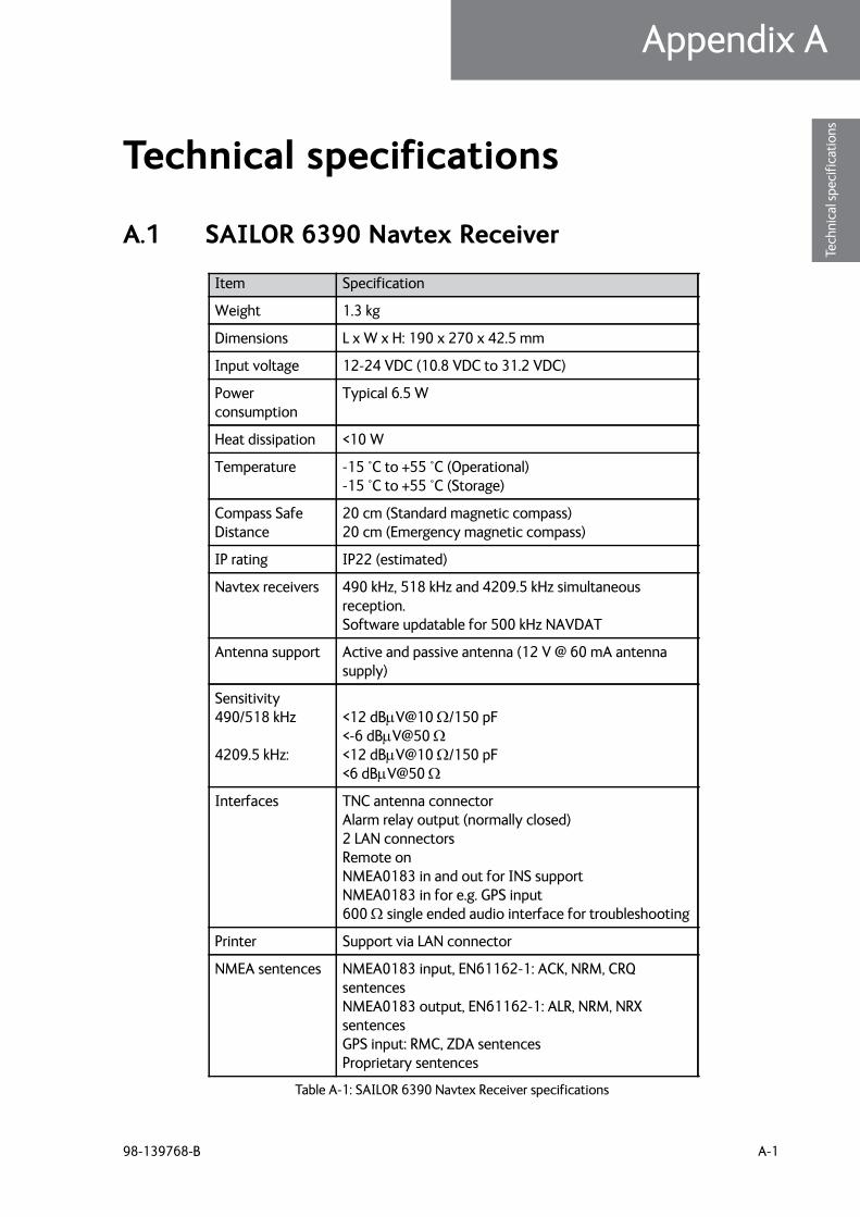
Technical specifications A
A.1 SAILOR 6390 Navtex Receiver
Item Specification
Weight 1.3 kg
Dimensions L x W x H: 190 x 270 x 42.5 mm
Input voltage 12-24 VDC (10.8 VDC to 31.2 VDC)
Power consumption
Typical 6.5 W
Heat dissipation <10 W
Temperature -15 °C to +55 °C (Operational) -15 °C to +55 °C (Storage)
Compass Safe Distance
20 cm (Standard magnetic compass) 20 cm (Emergency magnetic compass)
IP rating IP22 (estimated)
Navtex receivers 490 kHz, 518 kHz and 4209.5 kHz simultaneous reception.Software updatable for 500 kHz NAVDAT
Antenna support Active and passive antenna (12 V @ 60 mA antenna supply)
Sensitivity490/518 kHz
4209.5 kHz:
<12 dBV@10 /150 pF<-6 dBV@50 <12 dBV@10 /150 pF<6 dBV@50
Interfaces TNC antenna connectorAlarm relay output (normally closed)2 LAN connectorsRemote onNMEA0183 in and out for INS supportNMEA0183 in for e.g. GPS input600 single ended audio interface for troubleshooting
Printer Support via LAN connector
NMEA sentences NMEA0183 input, EN61162-1: ACK, NRM, CRQ sentencesNMEA0183 output, EN61162-1: ALR, NRM, NRX sentencesGPS input: RMC, ZDA sentencesProprietary sentences
Table A-1: SAILOR 6390 Navtex Receiver specifications
NMEA PCB in SAILOR 6390 Navtex Receiver
A-2 Appendix A: Technical specifications 98-139768-B
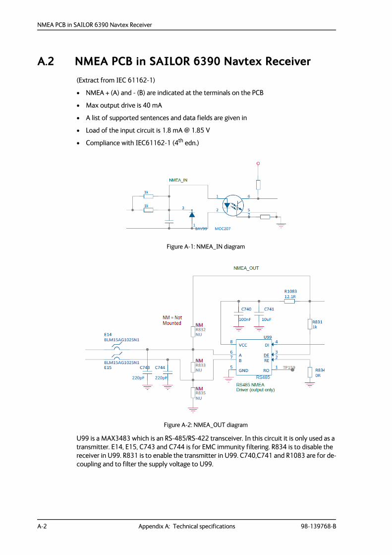
A.2 NMEA PCB in SAILOR 6390 Navtex Receiver(Extract from IEC 61162-1)
• NMEA + (A) and - (B) are indicated at the terminals on the PCB
• Max output drive is 40 mA
• A list of supported sentences and data fields are given in
• Load of the input circuit is 1.8 mA @ 1.85 V
• Compliance with IEC61162-1 (4th edn.)
U99 is a MAX3483 which is an RS-485/RS-422 transceiver. In this circuit it is only used as a transmitter. E14, E15, C743 and C744 is for EMC immunity filtering. R834 is to disable the receiver in U99. R831 is to enable the transmitter in U99. C740,C741 and R1083 are for de-coupling and to filter the supply voltage to U99.
Figure A-1: NMEA_IN diagram
Figure A-2: NMEA_OUT diagram
98-139768-B B-1
Appendix BBBBB
NM
EA se
nten
ces
NMEA sentences B
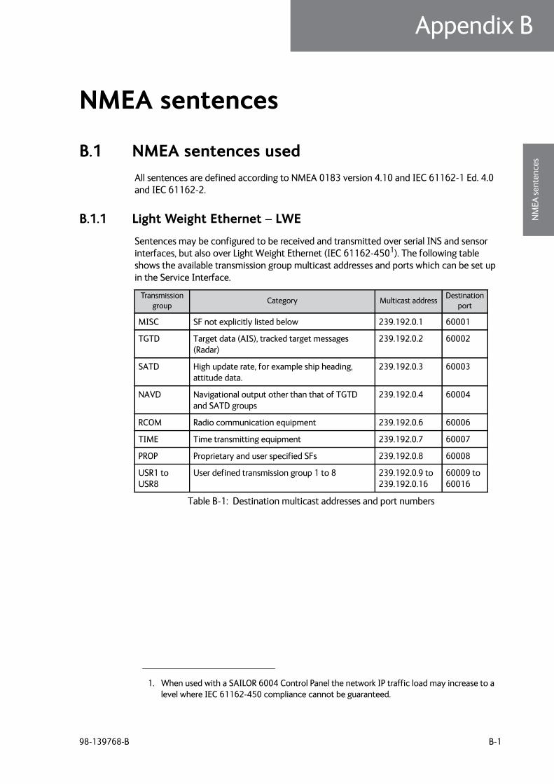
B.1 NMEA sentences usedAll sentences are defined according to NMEA 0183 version 4.10 and IEC 61162-1 Ed. 4.0 and IEC 61162-2.
B.1.1 Light Weight Ethernet – LWE
Sentences may be configured to be received and transmitted over serial INS and sensor interfaces, but also over Light Weight Ethernet (IEC 61162-4501). The following table shows the available transmission group multicast addresses and ports which can be set up in the Service Interface.
1. When used with a SAILOR 6004 Control Panel the network IP traffic load may increase to a level where IEC 61162-450 compliance cannot be guaranteed.
Transmissiongroup Category Multicast address Destination
port
MISC SF not explicitly listed below 239.192.0.1 60001
TGTD Target data (AIS), tracked target messages (Radar)
239.192.0.2 60002
SATD High update rate, for example ship heading, attitude data.
239.192.0.3 60003
NAVD Navigational output other than that of TGTD and SATD groups
239.192.0.4 60004
RCOM Radio communication equipment 239.192.0.6 60006
TIME Time transmitting equipment 239.192.0.7 60007
PROP Proprietary and user specified SFs 239.192.0.8 60008
USR1 to USR8
User defined transmission group 1 to 8 239.192.0.9 to 239.192.0.16
60009 to 60016
Table B-1: Destination multicast addresses and port numbers
NMEA sentences used
B-2 Chapter B: NMEA sentences 98-139768-B
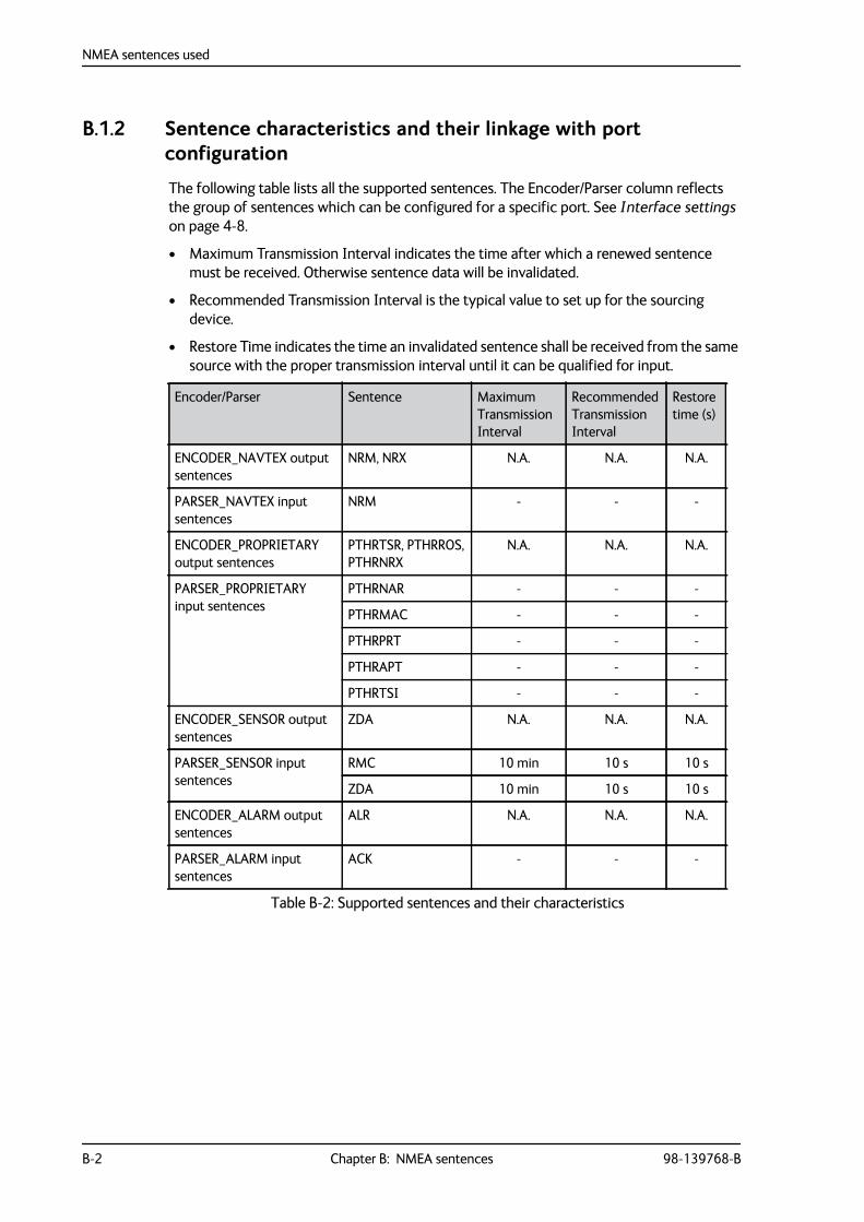
B.1.2 Sentence characteristics and their linkage with port configuration
The following table lists all the supported sentences. The Encoder/Parser column reflects the group of sentences which can be configured for a specific port. See Interface settings on page 4-8.
• Maximum Transmission Interval indicates the time after which a renewed sentence must be received. Otherwise sentence data will be invalidated.
• Recommended Transmission Interval is the typical value to set up for the sourcing device.
• Restore Time indicates the time an invalidated sentence shall be received from the same source with the proper transmission interval until it can be qualified for input.
Encoder/Parser Sentence Maximum TransmissionInterval
Recommended TransmissionInterval
Restoretime (s)
ENCODER_NAVTEX output sentences
NRM, NRX N.A. N.A. N.A.
PARSER_NAVTEX input sentences
NRM - - -
ENCODER_PROPRIETARY output sentences
PTHRTSR, PTHRROS,PTHRNRX
N.A. N.A. N.A.
PARSER_PROPRIETARY input sentences
PTHRNAR - - -
PTHRMAC - - -
PTHRPRT - - -
PTHRAPT - - -
PTHRTSI - - -
ENCODER_SENSOR output sentences
ZDA N.A. N.A. N.A.
PARSER_SENSOR input sentences
RMC 10 min 10 s 10 s
ZDA 10 min 10 s 10 s
ENCODER_ALARM output sentences
ALR N.A. N.A. N.A.
PARSER_ALARM input sentences
ACK - - -
Table B-2: Supported sentences and their characteristics
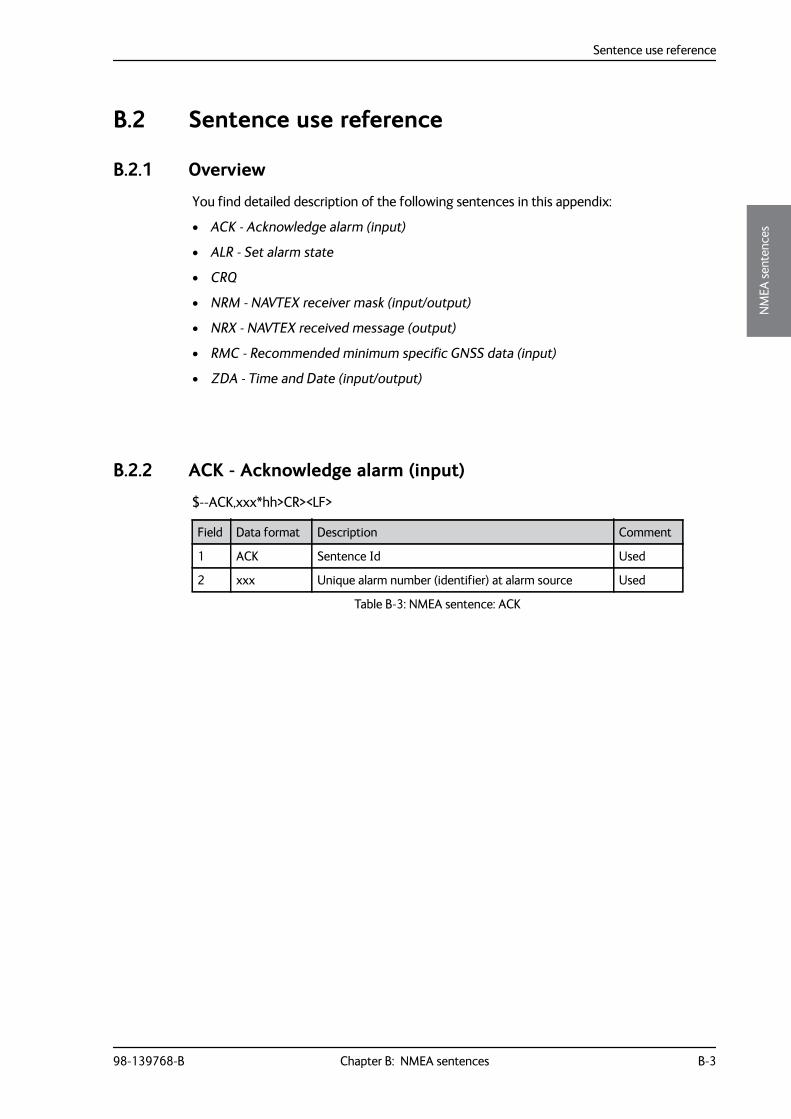
Sentence use reference
98-139768-B Chapter B: NMEA sentences B-3
BBBB
NM
EA se
nten
ces
B.2 Sentence use reference
B.2.1 Overview
You find detailed description of the following sentences in this appendix:
• ACK - Acknowledge alarm (input)
• ALR - Set alarm state
• CRQ
• NRM - NAVTEX receiver mask (input/output)
• NRX - NAVTEX received message (output)
• RMC - Recommended minimum specific GNSS data (input)
• ZDA - Time and Date (input/output)
B.2.2 ACK - Acknowledge alarm (input)
$--ACK,xxx*hh>CR><LF>
Field Data format Description Comment
1 ACK Sentence Id Used
2 xxx Unique alarm number (identifier) at alarm source Used
Table B-3: NMEA sentence: ACK
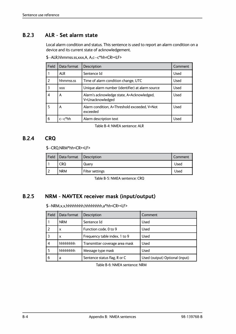
Sentence use reference
B-4 Appendix B: NMEA sentences 98-139768-B
B.2.3 ALR - Set alarm state
Local alarm condition and status. This sentence is used to report an alarm condition on a device and its current state of acknowledgement.
$--ALR,hhmmss.ss,xxx,A, A,c--c*hh<CR><LF>
B.2.4 CRQ
$--CRQ,NRM*hh<CR><LF>
B.2.5 NRM - NAVTEX receiver mask (input/output)
$--NRM,x,x,hhhhhhhh,hhhhhhhh,a*hh<CR><LF>
Field Data format Description Comment
1 ALR Sentence Id Used
2 hhmmss.ss Time of alarm condition change, UTC Used
3 xxx Unique alarm number (identifier) at alarm source Used
4 A Alarm’s acknowledge state, A=Acknowledged, V=Unacknowledged
Used
5 A Alarm condition, A=Threshold exceeded, V=Not exceeded
Used
6 c--c*hh Alarm description text Used
Table B-4: NMEA sentence: ALR
Field Data format Description Comment
1 CRQ Query Used
2 NRM Filter settings Used
Table B-5: NMEA sentence: CRQ
Field Data format Description Comment
1 NRM Sentence Id Used
2 x Function code, 0 to 9 Used
3 x Frequency table index, 1 to 9 Used
4 hhhhhhhh Transmitter coverage area mask Used
5 hhhhhhhh Message type mask Used
6 a Sentence status flag, R or C Used (output) Optional (input)
Table B-6: NMEA sentence: NRM
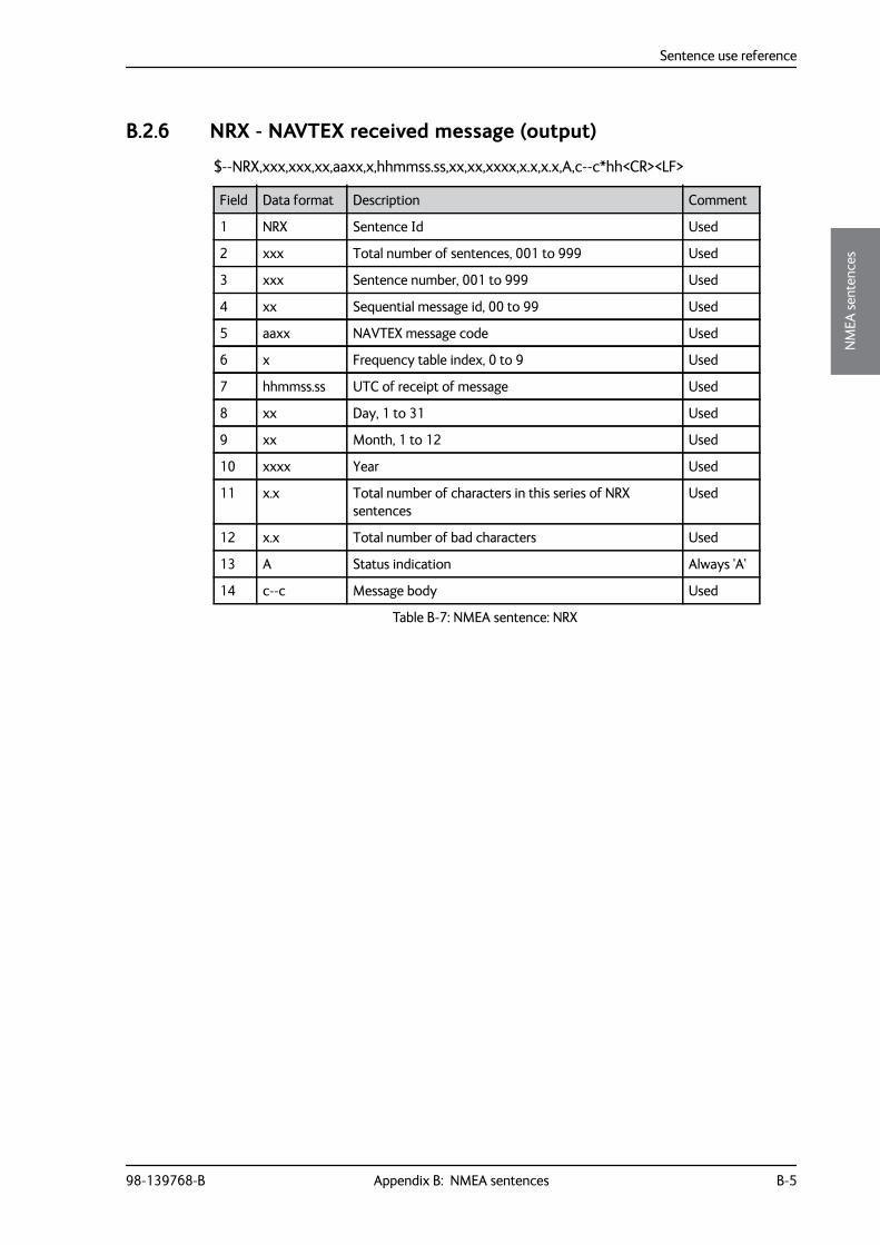
Sentence use reference
98-139768-B Appendix B: NMEA sentences B-5
BBBB
NM
EA se
nten
ces
B.2.6 NRX - NAVTEX received message (output)
$--NRX,xxx,xxx,xx,aaxx,x,hhmmss.ss,xx,xx,xxxx,x.x,x.x,A,c--c*hh<CR><LF>
Field Data format Description Comment
1 NRX Sentence Id Used
2 xxx Total number of sentences, 001 to 999 Used
3 xxx Sentence number, 001 to 999 Used
4 xx Sequential message id, 00 to 99 Used
5 aaxx NAVTEX message code Used
6 x Frequency table index, 0 to 9 Used
7 hhmmss.ss UTC of receipt of message Used
8 xx Day, 1 to 31 Used
9 xx Month, 1 to 12 Used
10 xxxx Year Used
11 x.x Total number of characters in this series of NRX sentences
Used
12 x.x Total number of bad characters Used
13 A Status indication Always 'A'
14 c--c Message body Used
Table B-7: NMEA sentence: NRX
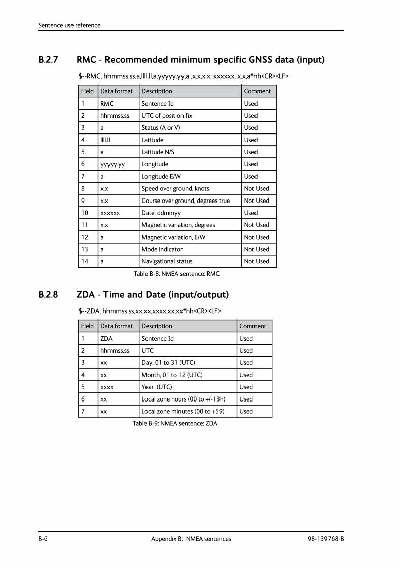
Sentence use reference
B-6 Appendix B: NMEA sentences 98-139768-B
B.2.7 RMC - Recommended minimum specific GNSS data (input)
$--RMC, hhmmss.ss,a,llll.ll,a,yyyyy.yy,a ,x.x,x.x, xxxxxx, x.x,a*hh<CR><LF>
B.2.8 ZDA - Time and Date (input/output)
$--ZDA, hhmmss.ss,xx,xx,xxxx,xx,xx*hh<CR><LF>
Field Data format Description Comment
1 RMC Sentence Id Used
2 hhmmss.ss UTC of position fix Used
3 a Status (A or V) Used
4 llll.ll Latitude Used
5 a Latitude N/S Used
6 yyyyy.yy Longitude Used
7 a Longitude E/W Used
8 x.x Speed over ground, knots Not Used
9 x.x Course over ground, degrees true Not Used
10 xxxxxx Date: ddmmyy Used
11 x.x Magnetic variation, degrees Not Used
12 a Magnetic variation, E/W Not Used
13 a Mode indicator Not Used
14 a Navigational status Not Used
Table B-8: NMEA sentence: RMC
Field Data format Description Comment
1 ZDA Sentence Id Used
2 hhmmss.ss UTC Used
3 xx Day, 01 to 31 (UTC) Used
4 xx Month, 01 to 12 (UTC) Used
5 xxxx Year (UTC) Used
6 xx Local zone hours (00 to +/-13h) Used
7 xx Local zone minutes (00 to +59) Used
Table B-9: NMEA sentence: ZDA
98-139768-B Glossary-1
3333
Glos
sary
Glossary
Glossary 3
DDC Direct Current
DHCP Dynamic Host Configuration Protocol. A protocol for assigning dynamic IP addresses to devices on a network. With dynamic addressing, a device can have a different IP address every time it connects to the network.
DNS Domain Name System. A system translating server names (URLs) to server addresses.
GGMDSS Global Maritime Distress and Safety System. The system is intended to perform the
following functions: alerting (including position determination of the unit in distress), search and rescue coordination, locating (homing), maritime safety information broadcasts, general communication, and bridge-to-bridge communication.
GNSS Global Navigation Satellite System
GPL General Public License
GPS Global Positioning System
IINS Integrated Navigation System
LLAN Local Area Network. A computer network covering a small physical area, like a home,
office, school or airport. The defining characteristics of LANs, in contrast to wide-area networks (WANs), include their usually higher data-transfer rates, smaller geographic area, and lack of a need for leased telecommunication lines.
LGPL Lesser General Public License
LPR Line Printer Remote. Simple network protocol.
NNAVDAT High Speed NAVtex DATa sent out on 500 kHz. Not yet part of mandatory Navtex
reception, but mentioned in ITU-R M.2010 and ITU-R M.2201.
Glossary
Glossary-2 98-139768-B
NMEA National Marine Electronics Association (standard). A combined electrical and data specification for communication between marine electronic devices such as echo sounder, sonars, anemometer (wind speed and direction), gyrocompass, autopilot, GPS receivers and many other types of instruments. It has been defined by, and is controlled by, the U.S.-based National Marine Electronics Association.
RRSTP Rapid Spanning Tree Protocol is typically able to respond quickly to changes in network
topology or in case of a physical link failure. RSTP provides significantly faster spanning tree convergence after a topology change.
Rx Receive
TTMA Thrane Management Application
Tx Transmit (Ethernet)
98-139768-B Index-1
4444
Inde
x
Index
Index 4
Aalarm, 5-5
acknowledge, 5-5relay, toggle, 4-20
alarmsINS, 5-6Navtex, 5-5printer, 5-6
antennaconnector, 3-4placing, 3-4select type, 4-7
appdisplay in bottom bar, 4-3install, 4-3uninstall, 4-3update, 4-3
applications, 4-2audio source, 4-20
change, 4-20auto range, 4-7Automatic mode, 4-7
Bbackup
configuration, 4-16bottom bar
display app, 4-3brightness, 4-1buzzer, 2-3
Ccable specifications, 3-6clear messages, 4-16coast station
add new, 4-14filtering, 4-7list, reset, 4-15update, 4-14
compass safe distance, -iii, 3-2configuration
load, 4-16save, 4-16
connection lost, 4-4, 4-6connector
LAN, 3-5Navtex antenna, 3-4overview, 2-2
Ddatabase
download all, 4-5store messages, 4-5
debugaudio source, 4-20spurious, 4-20
default settingsreset to, 4-16
delete messages, 4-16delivery
items included, 3-1DHCP, 4-12dimming function, 4-1display
brightness, 4-1
EEthernet, 3-5
connector, 3-5settings, 4-11transmission group, 4-14
Ffactory default
coast station list, 4-15factory reset, 4-16filtering coast stations, 4-7fuse
size, 3-1
GGMDSS installations, 3-5

Index
Index-2 98-139768-B
Iinstall app, 4-2installation, 3-1invalid time stamp
alarm, 5-6IP address
Control Panel, 4-3, 4-5DHCP or static, 4-12Navtex Receiver, 4-4, 4-5printer, 4-10
LLAN
connector, 3-5license
software, -iiLWE
multicast addresses, B-1LWE ID, 4-11
Control Panel, 4-12Navtex Receiver, 4-12
MMAC address
Control Panel, 4-3messages
clear, 4-16store, 4-5
multicast addresses, B-1
NNAVDAT, 2-2Navtex antenna, 3-4
placing, 3-4select type, 4-7
Navtex areasadd coast station, 4-14
Navtex DB Dump, 4-5Navtex frequencies, 2-1Navtex message
example, 2-3Navtex messages
store, 4-5
Navtex Receiverspecifications, A-1use stand alone, 2-4use with Control panel, 2-3
night mode, 2-3, 4-1NMEA sentences, B-2NMEA tracer, 4-18
Oopen source licences, 4-3
Ppart numbers, 2-4password, 4-3, 4-6placing
antenna, 3-4print server, 4-11printer
3rd party, setup, 4-11disable, 4-11IP address, 4-10ThraneLINK compatible, setup, 4-11
printer settings, 4-10
Rreboot
power cycle, 4-16Remote Device Name, 4-7reset, 4-16
coast stations, 4-15RF exposure, -iiiRF reception level, 4-19RF reception levels, 4-19RSTP, 4-12RX self test
Navtex Receiver, 5-8
Sself test, 4-3, 4-20
Control Panel, 4-3Navtex Receiver, 5-8
SensorNMEA sentences, 4-9
Index
98-139768-B Index-3
4444
Inde
x
sentenceACK, B-3ALR, B-4NRM, B-4NRX, B-5RMC, B-6ZDA, B-6
Sentence White ListINS, 4-8LWE, 4-14Sensor, 4-9
sentences supported, B-2Service Interface
access, 4-4settings
Ethernet, 4-11printer, 4-10
softwareuninstall, 4-3
software license, -iisoftware update
service interface, 5-3TMA, 5-2via Control Panel, 4-3
software versionTMA, 4-4
specifications, A-1Navtex Receiver, A-1
Static IP, 4-12System Function ID, 4-7
TTalker ID White List
INS, 4-8LWE, 4-14Sensor, 4-9
technical data, A-1test message, 4-20
generate, 4-20time
invalid, 5-6TMA
add search path, 5-2software update, 5-2software version, 5-2specific software, 5-3version, 4-4
tracer tool, 4-18transmission group, 4-14, B-1
troubleshooting, 5-7
Uuninstall, 4-3unpacking
items included, 3-1use scenario
stand alone, 2-4with Control Panel, 2-3
Vverification, 4-18
check list, 4-17installation tests, 4-20NMEA Trace, 4-18RF reception levels, 4-19
Wwarranty, -iii, 5-10

98-139768-Bwww.cobham.com/satcom