Embed Size (px)
Citation preview

TECHNICAL MANUAL
SAILOR SYSTEM 5000 MF/HF 150W FCC

Disclaimer
Any responsibility or liability for loss or damage in connection with the use of this product and the accompany-ing documentation is disclaimed by Thrane & Thrane. The information in this manual is provided for information purposes only, is subject to change without notice, may contain errors or inaccuracies, and represents no com-mitment whatsoever by Thrane & Thrane. This agreement is governed by the laws of Denmark.
Manuals issued by Thrane & Thrane are periodically revised and updated. Anyone relying on this information should satisfy himself/herself as to the most current version. Providers with access to Thrane & Thrane’s Ex-tranet may obtain current copies of manuals at: http://extranet.thrane.com.
Thrane & Thrane is not responsible for the content or accuracy of any translations or reproductions, in whole or in part, of this manual from any other source.

MF/HF 150W
0745
CONTENTS
1 General information 1-11.1 Introduction 1-11.2 Technical data 1-1
2 Installation 2-12.1 Description 2-12.2 Mounting the units 2-12.3 Ground connections 2-62.4 Grounding considerations 2-62.5 Antennas 2-82.6 Power supply 2-112.7 Interconnection of units 2-122.8 Connector mounting instructions 2-192.9 Position and time information 2-202.10 DSC programming 2-202.11 Battery alarm adjustment 2-212.12 Options menu - setting up the system 2-212.13 Factory resetting / MMSI resetting 2-232.14 Enabling the 6 ch scanning DSC Watch Receiver 2-232.15 Enabling the Telex operation 2-242.16 Telex operation 2-242.17 Final installation check 2-26
3 Technical description 3-13.1 Control Unit 3-13.2 Transceiver Unit 3-13.3 Control/Intercon module 60-122878 3-13.4 Synth. and DSC WR module 60-122879 3-13.5 RX/EX signal path module 60-122880 3-23.6 PA and Filters module 60-123937 3-23.7 SMPS module 60-122882 3-23.8 Transceiver unit block diagram 3-33.9 Transceiver unit interconnection diagram 3-43.10 Antenna Tuning Unit 3-53.11 Antenna Tuning Unit block diagram 3-53.12 Power control and protection system 3-63.13 Power control and protection system 3-7
4 Service 4-14.1 Preventive maintenance 4-14.2 Realignment of master oscillator 4-14.3 Software update 4-24.4 Trouble shooting 4-24.5 Power protection 4-34.6 Selftest 4-5
5 Spare part exchange 5-15.1 Disassembling the Transceiver Unit 5-15.2 Transceiver Unit module location 5-25.3 Required service tool 5-45.4 Accessory list 5-4

1-1
MF/HF 150W
0812
1 General information
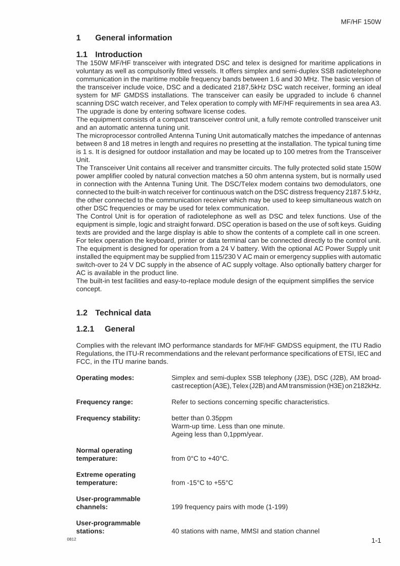
1.1 IntroductionThe 150W MF/HF transceiver with integrated DSC and telex is designed for maritime applications involuntary as well as compulsorily fitted vessels. It offers simplex and semi-duplex SSB radiotelephonecommunication in the maritime mobile frequency bands between 1.6 and 30 MHz. The basic version ofthe transceiver include voice, DSC and a dedicated 2187,5kHz DSC watch receiver, forming an idealsystem for MF GMDSS installations. The transceiver can easily be upgraded to include 6 channelscanning DSC watch receiver, and Telex operation to comply with MF/HF requirements in sea area A3.The upgrade is done by entering software license codes.The equipment consists of a compact transceiver control unit, a fully remote controlled transceiver unitand an automatic antenna tuning unit.The microprocessor controlled Antenna Tuning Unit automatically matches the impedance of antennasbetween 8 and 18 metres in length and requires no presetting at the installation. The typical tuning timeis 1 s. It is designed for outdoor installation and may be located up to 100 metres from the TransceiverUnit.The Transceiver Unit contains all receiver and transmitter circuits. The fully protected solid state 150Wpower amplifier cooled by natural convection matches a 50 ohm antenna system, but is normally usedin connection with the Antenna Tuning Unit. The DSC/Telex modem contains two demodulators, oneconnected to the built-in watch receiver for continuous watch on the DSC distress frequency 2187.5 kHz,the other connected to the communication receiver which may be used to keep simultaneous watch onother DSC frequencies or may be used for telex communication.The Control Unit is for operation of radiotelephone as well as DSC and telex functions. Use of theequipment is simple, logic and straight forward. DSC operation is based on the use of soft keys. Guidingtexts are provided and the large display is able to show the contents of a complete call in one screen.For telex operation the keyboard, printer or data terminal can be connected directly to the control unit.The equipment is designed for operation from a 24 V battery. With the optional AC Power Supply unitinstalled the equipment may be supplied from 115/230 V AC main or emergency supplies with automaticswitch-over to 24 V DC supply in the absence of AC supply voltage. Also optionally battery charger forAC is available in the product line.The built-in test facilities and easy-to-replace module design of the equipment simplifies the serviceconcept.
1.2 Technical data
1.2.1 General
Complies with the relevant IMO performance standards for MF/HF GMDSS equipment, the ITU RadioRegulations, the ITU-R recommendations and the relevant performance specifications of ETSI, IEC andFCC, in the ITU marine bands.
Operating modes: Simplex and semi-duplex SSB telephony (J3E), DSC (J2B), AM broad-cast reception (A3E), Telex (J2B) and AM transmission (H3E) on 2182kHz.
Frequency range: Refer to sections concerning specific characteristics.
Frequency stability: better than 0.35ppmWarm-up time. Less than one minute.Ageing less than 0,1ppm/year.
Normal operatingtemperature: from 0°C to +40°C.
Extreme operatingtemperature: from -15°C to +55°C
User-programmablechannels: 199 frequency pairs with mode (1-199)
User-programmablestations: 40 stations with name, MMSI and station channel

1 General information MF/HF 150W
Output power: Refer to sections concerning Receiver / Transmitter characteristics
Supply voltage: Nominal 24V DC floating (-10 +30%)With optional external AC power supply:115/230V AC 50/60 Hz. Automatic change-over to DC in the absence ofAC supply
Power consumption: 150W:Rx, 60W (approx. at 24V DC)Tx, SSB speech: 175WTx, SSB two-tone: 300WTx, DSC/TELEX: 420W
Compass safe distance: Compass safe distance in accordance with ISO/R 694 are given belowin metres.
Unit Standard Steering5.4°/H 18°/H
Control Unit 1.2 0.5Transceiver Unit 0.4 0.2Antenna Tuning Unit 0.3 0.1Handset 0.3 0.2Cradle 1.1 0.75070 Loudspeaker 2.2 1.6
1.2.2 Receiver characteristics
General: Complies with ETSI 300373 in the ITU marine bands.
Reception: Mode Rx/Tx antenna plug DSC/Telex antenna plugSSB/AM XDSC XTelex X
Frequency range: 150 kHz to 30 MHz.
Frequency resolution: 100 Hz by keyboard entry.10 Hz, 100 Hz or 1 kHz search/fine-tune facility is provided.
Input impedance: Rx/Tx : 50 ohm
The Antenna is matched by the antenna amplifier in the Aerial Coupler.
DSC/Telex: 50 ohm12V DC / 20 mA is available for eventual use of active antenna.
Sensitivity: Telephony(J3E): below 11 dBµV for 20 dB SinadBroadcast (A3E): below 25 dBµV for 20 dB SinadDSC/Telex (J2B): below 0 dBµV
Intermodulation: Telephony (J3E): Wanted Signal: 30 dBµVIntermodulation level: above 80 dBµVTelex(J2B): Wanted Signal: 30 dBµVIntermodulation level: above 90 dBµVDSC (J2B): Wanted Signal: 20 dBµVIntermodulation level: above 80 dBµV
Spurious rejection: above 70 dB
Audio output power: Build-in loudspeakerOptional loudspeaker output 4 W typical with less than 10 % distortion.Output intended for 8 ohm loudspeaker.1-2 0812
1 General information MF/HF 150W
1.2.3 Transmitter characteristics
General: Complies with ETSI 300373 and FCC or better in the ITU marine bands.The Transmitter characteristics are with the Aerial Coupler included.
Frequency range: The ITU marine bands in the frequency range 1605 kHz to 30 MHz
Frequency resolution: 100 Hz.
Output power: SSB:150W PEP ± 1.4 dB into 50 ohm Antenna, voice for a duty cycle less than55% and modulation rate greater than 3 baud.
DSC/Telex:85W ± 1.4 dB
Power reduction: Low power: approx. 20 W PEP.
Intermodulation: below -31 dB/PEP.
Spurious Emission: below -60 dB/PEP.
Hum and noise: Less than - 40 dB/PEP.
1.2.4 DSC Watch receiver characteristics
General: Complies with ETSI 300338.
Reception: DSC/Telex antenna plug.
Frequency range: Scanning the following frequencies:2187,5 KHz, 4207,5 kHz, 6312,0 KHz, 8414,5 kHz, 12577,0 KHz,16814,5 kHz.
Input impedance: DSC/Telex: 50 ohm.12V DC / 20 mA is available for eventual use of active antenna.
Sensitivity: DSC (J2B): below 0 dBµV.
Intermodulation: DSC (J2B): Wanted Signal: 20 dBµV.Intermod. level: above 70 dBµV.
Spurious rejection: above 70 dB.
1-30812
1 General information MF/HF 150W
1-4 0745
1.2.5 Aerial coupler characteristics
General: Complies with ETSI 300373 and FCC or better in the ITU marine bands.
Frequency range: 1.6 MHz - 27 MHz.
Aerial requirements: 8-18 m wire and/or whip aerial.
Aerial tuning: Fully automatic with no presetting.
Tuning speed: 0.1 - 8 sec.
Power capability: 350W PEP into 50 ohm Antenna.
Extreme operatingtemperature: from -25°C to +55°C.
1.2.6 DSC/Telex modem characteristics
DSC: DSC Equipment class: Class A.
Protocols: ITU-R M. 493.12, M. 541-6, and M. 1082.
Ship’s identity: 9-digit identity number.
Navigator interface: According to IEC 61162-1GLL, RMC, ZDA, GGA.
TELEX: Protocols: ITU-R M. 625-2 (incl. M. 476-4), M. 490,M. 491-1, and 492-5 NBDP telex in ARQ, FECand SELFEC modes.
Ship’s identity: 5- and/or 9-digit identity number.
1.2.7 Dimensions and weight
Control Unit:CU5100: Width: 200 mm (7,9")
Height: 100 mm (3,9")Depth: 80 mm (3.1")Weight: 3.3 kg (7.3 lbs)
Transceiver UnitTU5160: Width: 390 mm (15.3")
Height: 445 mm (17.5")Depth: 127 mm (5")Weight: 19 kg (41.9 lbs)
Antenna Tuning Unit:ATU5215: Width: 290 mm (11.4")
Height: 500 mm (19.7")Depth: 80 mm (3.1")Weight: 3.3 kg (7.3 lbs)
Equipment category: Control Unit: Protected,Transceiver Unit: Protected,Antenna Tuning Unit: Exposed.

2-1
MF/HF 150W
0812
2 Installation
2.1 DescriptionCorrect installation of the equipment is important for maximum performance and reliability. Antennas andearth connections must be installed with the greatest care using corrosion resistant materials.Cable routing shall be made so the cables are protected from physical damage. Sharp cable bendsespecially on coaxial cables must be avoided and a sufficient number of clips or straps should be usedto secure the cables.
2.2 Mounting the units
Mounting the Control Unit (CU)One Unit shall be connected to the Transceiver Unit using the build-in local area network (ScanBus). TheCU may be mounted up to 100m from the Transceiver Unit using just one Multicable 5 x 2 x 0.5 mm2
screened.The Control Unit may be tabletop or bulkhead mounted.
Control Units with mounting bracket
40536A
200
235
100
140
100
Mounting option Drilling plan
40615
Tilting +/-45 °
7.00
14.50
209.00
181.00
55.00
41.00
4 x ø4
Control unit connector panel
40616
Handset AUX SCAN-BUS
Keyboard Data Printer
Weight:Control Unit 1.4 kg.Mounting Bracket 0.3 kg.
2 Installation MF/HF 150W
0812
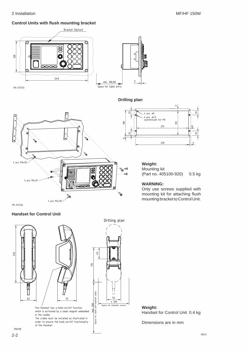
Control Units with flush mounting bracket
99-127233
Bracket (Option)
Space for Cable entry
min. 100.00
240
120
3
Drilling plan
4 pcs M3x30
4 pcs M4x30
4 pcs M4x12
99-127234
228 6
6108
102
9
219 10
20
20
20
20
4 pcs. ø5
4 pcs. ø3.5
countersunk for M3
Weight:Mounting kit(Part no. 405100-920) 0.5 kg
WARNING:Only use screws supplied withmounting kit for attaching flushmounting bracket to Control Unit.
Handset for Control Unit
This Handset has a hook-on/off function,
which is activated by a small magnet embedded
in the ceadle.
The cradle must be installed as illustrated in
order to ensure the hook-on/off functionality
of the Handset.
7562
226
* 120
min. 200
Space for handset access
Space for cable and handset cable
54
45
135
39655B
Drilling plan
Weight:Handset for Control Unit 0.4 kg
Dimensions are in mm
2-2

2 Installation MF/HF 150W
2-30745
Mounting the Transceiver Unit (TU)The Transceiver Unit should be installed in a dry place and consideration should be given to accessibilityfor servicing. It is important to provide sufficient airspace below, above and in front of the unit for adequateair circulation through the cooling fins. The drawing below shows the outer dimensions, mountingpossibilities and the minimum distance to other objects, as well as a drilling plan.
391
430
360
350
88
145
1
1
2
4 x ø8
Cable fitting
37955A
1) Space for cable: min. 150 mm2) Space for airflow and service: min. 500 mm
Cable fitting
80
56
57.6
70
12
38417
Dimensions are in mm

2 Installation MF/HF 150W
2-4
Mounting the Antenna Tuning Unit (ATU)The Antenna Tuning Unit may be mounted up to 100 metres from the Transceiver Unit using just one RG-213/U coaxial cable. The unit should be installed near the antenna feed point.
37978
271
1216
416
4
145
50
170
76.5
75
2)
3)
1)
290
80
200
352
6 x ø6.50
1) Space to nearest overhang: min. 50 mm2) Space for service access: min. 500 mm3) Space for cable and service access: min. 200 mmDimensions are in mm
0745
2 Installation MF/HF 150W
2-50745
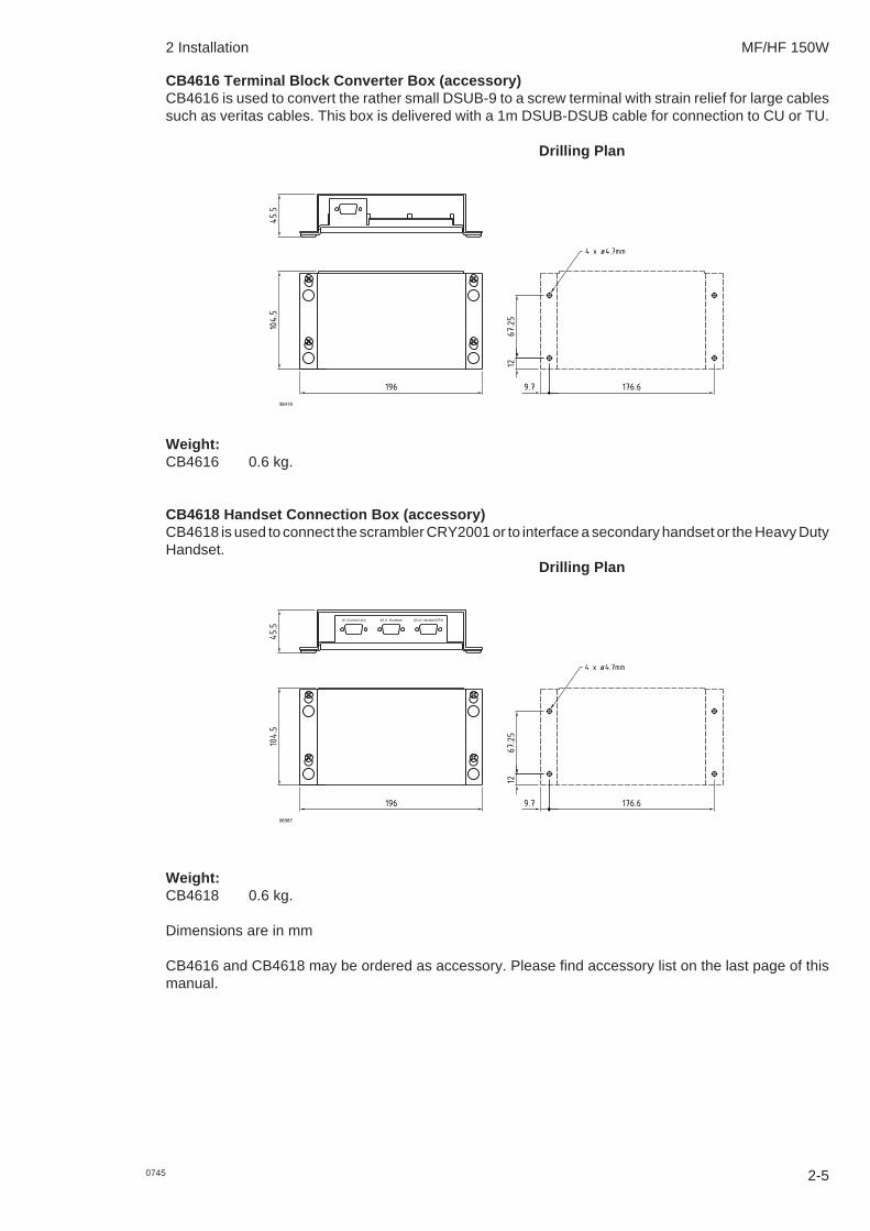
CB4616 Terminal Block Converter Box (accessory)CB4616 is used to convert the rather small DSUB-9 to a screw terminal with strain relief for large cablessuch as veritas cables. This box is delivered with a 1m DSUB-DSUB cable for connection to CU or TU.
Drilling Plan
176.6196
12
9.7
67.25
45.5
104.5
4 x ø4.7mm
38419
Weight:CB4616 0.6 kg.
CB4618 Handset Connection Box (accessory)CB4618 is used to connect the scrambler CRY2001 or to interface a secondary handset or the Heavy DutyHandset.
Drilling Plan
176.6196
12
9.7
67.25
45.5
104.5
4 x ø4.7mm
38387
X1 (Control Unit) X2 (1. Handset) X3 (2. Handset/CRY)
Weight:CB4618 0.6 kg.
Dimensions are in mm
CB4616 and CB4618 may be ordered as accessory. Please find accessory list on the last page of thismanual.

2 Installation MF/HF 150W
2.3 Ground connections
Antenna Tuning UnitAs the earth connection of a transmitter is a very importantpart of the antenna system, it is of the utmost importanceto keep in mind that the earth connection of the AntennaTuning Unit must have the lowest possible RF-impedance.Losses in the earth connection will result in a decrease inradiated power which means that the range of thetransmitter will be reduced. In steel ships a 100 x 0.5 mmcopper strap as short as possible is connected betweenthe earth terminal at the bottom of the Antenna TuningUnit and two or three 1/2" or M12 bolts welded to thesuperstructure. Vessels constructed of non-conductingmaterials must be equipped with a copper earth platehaving a minimum area of 1 square metre mounted belowthe water line. From a copper earth bolt hard soldered tothe earth plate a 100 x 0.5 mm copper strap is run,preferably uninterrupted to the earth terminal at the bottomof the Antenna Tuning Unit.Should it be necessary to break the copper strap, for example to pass through a deck, two or three 1/2"or M12 bolts should be used for this feed through. On wooden ships having a superstructure of metal,this superstructure should also be effectively connected to the copper strap by using stainless steel boltsand preferably pieces of stainless steel strips between the metal parts. On fibre glass boats, such asyachts and sailing boats, it may be difficult to install a sufficiently good earth. Short copper straps arebolted to conducting parts on the engine, the keel and other conducting objects. Many copper straps canbe glued to the inner surface of the hull below the water line to produce a large capacitance to the water.It is important that the total area of copper is large and that the distance between the copper surface andthe water is as small as possible. The copper straps are connected directly to the ATU.
Transceiver Unit and Control UnitThe Transceiver Unit is preferably groundedseparately to the ships metal in the shortest possibleway. A 10 to 16mm sq. ground wire is connected tothe ground terminal (cable clamp) at the bottom ofthe unit.
2.4 Grounding considerationsProper system grounding is one of the most important installation details.Two areas of grounding must be considered:
a) The ground connection between the ATU and earth ground plane.b) The ground connection of the TU and the externally connected equipment.
Each area requires separate considerationseven though they are interrelated. Ideally theControl Unit, Transceiver Unit, Antenna Tun-ing Unit and the antenna ground-plane musthave the same RF ground potential. Unfortu-nately this situation is seldom achieved, butinterference problems will be reduced alongwith how close to this “ideal” the grounding ofthe installation is performed.On some installations ground loops will causeproblems. A ground loop is caused by morethan one ground path for a given unit. This willintroduce circulating RF currents which maycause malfunction of other equipment onboardthe ship as well as a “hot” handset.
2-6 0745
Copper strap 100 x 0.5mm
Dimensions are in mm.
37872
20
50
80
6
6.6
R3.3
11mm
ø5.4mmcrimp
wire
37836
ATUTU
CU
'Hot' Handset
RF current loop
Ground-Plane
Not OK installation
Zg
37867

2 Installation MF/HF 150W
2-70745
Antenna startThe vertical antenna always start at its electrical ground-plane, whether or not it is physically mountedthere. First determine the antenna’s electrical ground-plane, which is where the ATU must be mounted.Where possible always take the ATU to the ground, not the ground to the ATU.In case of a fibreglass boat, the ground-plane may well be at the hull grounding terminal. Then this is wherethe Antenna Tuning Unit should go and this is where the antenna actually starts.
ATU
TUCU
OK installation
Not a 'Hot' Handset
Ground-Plane
37868The antenna starts here
RF ground loopIt is not always possible or practical to mount the ATU using a very short strap to the actual ground-plane.In such a case the coaxialcable may be connected between units with different ground potentials causingRF loop-current to flow.
ATUTU
CU
Not OK installation
coaxial cable
RF current loop
Ground-Plane
Zg
37869
Vg = Iant x Zg
Minimizing ground loopsBy routing the coax cable very close together with the ATU ground strap (secure good RF couplingbetween the two) all the way down to the ground-plane, there will be no RF ground loop left to generatethe interference.
ATUTU
CU
coaxial cable
Ground-Plane
OK installation
Zg
37870
Vg = Iant x Zg

2 Installation MF/HF 150W
0745
2.5 Antennas
Transceiver AntennaThe equipment is used with common transmitting and receiving antenna. The antenna should be erectedin the open, away from conducting object such as derricks etc. which may cause reduction of the radiatedpower. Insulators should be of the best type having low leakage even when wet. Stays, wires, steel mastsetc. should be either effectively earthed or insulated. The antenna should also be kept as far away aspossible from electrical equipment in order to minimize noise. Electrical installation such as cable braiding(screens) and instruments in the vicinity of the antenna should be earthed effectively, and the instrumentsin question should be fitted with noise-interference suppression devices, effective in the range 0.1 MHzto 30 MHz to avoid malfunction of these instruments. The Antenna Tuning Unit will tune on any frequencyin the range 1.6 to 27 MHz to good whip and/or wire installations of 12 to 18 meters total electrical length.Shorter antennas, electrical length down to 8 meters can be used. Where possible long antennas shouldbe installed to maximize the radiated power in the lower frequency bands.
In general a 12 meter antenna installation can be made using an 8 meter whip and 4.5 meter feeder ora 10 meter whip and 2.5 meter feeder. In both cases the whip should be mounted on a pole allowing forthe feeder to be erected at an angle of no less than 60 degrees to create a vertical antenna system. Usinghorizontal feeders or feeders mounted at an angle below 45 degrees usually transform the antennaradiation resistance to a lower value reducing the radiated power. Furthermore, the total antenna systemshould be kept well away from conductive objects such as the mast. Usually a horizontal distance of morethan 4 meters will create good results.Note: If a whip antenna is used this should have an anti-corona ball as a top termination to preventcrackling noise in the receiver.
The antenna is terminated at the insulator at the top of theAntenna Tuning Unit. The insulator must be relieved frommechanical stress by using max. 1 metre flexible wirebetween the insulator and a support. To maximize theradiated power and avoid flash over keep distance to metalparts as long as possible. All wire junctions in the antennasystem must be made with cable lugs of correct sizeaccording to the wire gauge. This will prevent bad connec-tions due to corrosion. For further corrosion proofing greasemay be applied to the cable joints.
2-8

2 Installation MF/HF 150W
2-90745
Recommended ATU installationOn a metal-hull vessel. Mount the Antenna Tuning Unit on a custom-built bracket made from iron anglebars (refer to figure on previous page).
Antenna Tuning Unit bracket Antenna Tuning Unit bracketwelded to the railing. welded to the deck.
2 Installation MF/HF 150W
2-10 0745
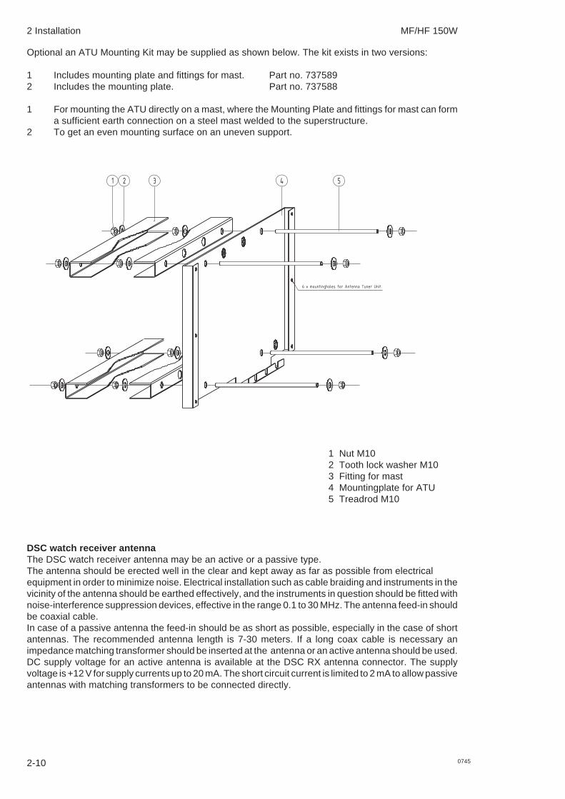
Optional an ATU Mounting Kit may be supplied as shown below. The kit exists in two versions:
1 Includes mounting plate and fittings for mast. Part no. 7375892 Includes the mounting plate. Part no. 737588
1 For mounting the ATU directly on a mast, where the Mounting Plate and fittings for mast can forma sufficient earth connection on a steel mast welded to the superstructure.
2 To get an even mounting surface on an uneven support.
6 x mountingholes for Antenna Tuner Unit.
5 Treadrod M10 64.005
4 Mountingplate 237218
1 2 3 4 5
DSC watch receiver antennaThe DSC watch receiver antenna may be an active or a passive type.The antenna should be erected well in the clear and kept away as far as possible from electricalequipment in order to minimize noise. Electrical installation such as cable braiding and instruments in thevicinity of the antenna should be earthed effectively, and the instruments in question should be fitted withnoise-interference suppression devices, effective in the range 0.1 to 30 MHz. The antenna feed-in shouldbe coaxial cable.In case of a passive antenna the feed-in should be as short as possible, especially in the case of shortantennas. The recommended antenna length is 7-30 meters. If a long coax cable is necessary animpedance matching transformer should be inserted at the antenna or an active antenna should be used.DC supply voltage for an active antenna is available at the DSC RX antenna connector. The supplyvoltage is +12 V for supply currents up to 20 mA. The short circuit current is limited to 2 mA to allow passiveantennas with matching transformers to be connected directly.
1 Nut M102 Tooth lock washer M103 Fitting for mast4 Mountingplate for ATU5 Treadrod M10
2 Installation MF/HF 150W
2-110745
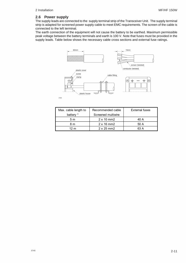
2.6 Power supplyThe supply leads are connected to the supply terminal strip of the Transceiver Unit. The supply terminalstrip is adapted for screened power supply cable to meet EMC requirements. The screen of the cable isconnected to the left terminal.The earth connection of the equipment will not cause the battery to be earthed. Maximum permissiblepeak voltage between the battery terminals and earth is 100 V. Note that fuses must be provided in thesupply leads. Table below shows the necessary cable cross sections and external fuse ratings.
60mm 15mm
plastic cover
screw
clamp
plastic house
screen (twisted)
conductor (twisted)
cable fitting
37835
Max. cable length to Recommended cable External fusesbattery * Screened multiwire
5 m 2 x 10 mm2 40 A8 m 2 x 16 mm2 50 A12 m 2 x 25 mm2 63 A

2 Installation MF/HF 150W
2-12 0745
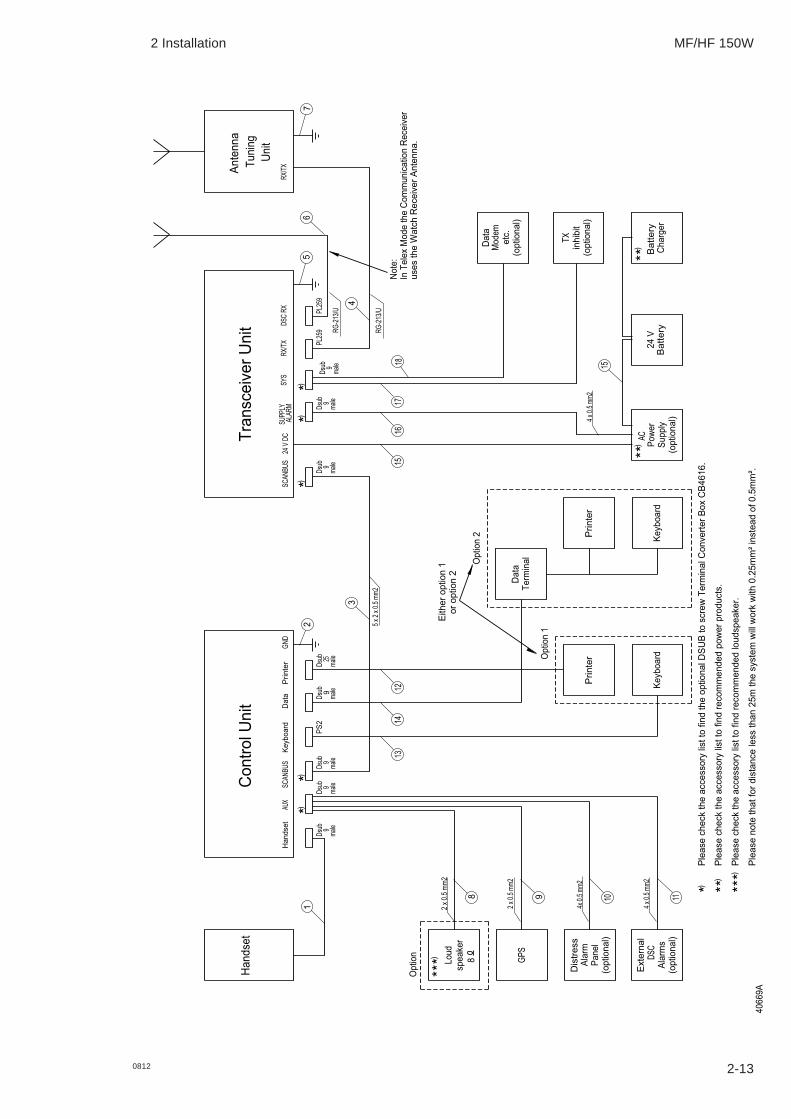
2.7 Interconnection of units
Transceiver Unit connector panel
37849
24 V DC
SCANBUS
1 1
SYS SUPPLY ALARM
1
DSC RX RX/TX+-
Control Unit connector panel
40616
Handset AUX SCAN-BUS
Keyboard Data Printer
Antenna Tuning Unit connector panel
40631
2 Installation MF/HF 150W
2-130812
4066
9A
Handset
Control Unit
Transceiver Unit
Antenna
Tuning
Unit
Handset
AUX
Keyboard
SCANBUS
SCANBUS
24 V
DC
SUPPLY
ALARM
SYS
RX/TX
DSC
RX
RX/TX
Loud
speaker
GPS
Distress
Alarm
Panel
(optional)
External
DSC
Alarms
(optional)
AC
Power
Supply
(optional)
24
V
Battery
Battery
Charger
Dsub
9male
Dsub
9male
Dsub
9male
Dsub
9male
Dsub
9male
PL25
9PL25
9
RG-21
3/U
5 x
2 x
0.5
mm2
2 x
0.5
mm2
2 x
0.5
mm2
4x 0.5
mm2
4 x
0.5
mm2
4 x
0.5
mm2
Data
Modem
etc.
(optional)
RG-21
3/U
1
34
6
18
TX
inhibit
(optional)
8 9 10 11
17
16
15
25
7
15
*)
*)
*)) *
*)
Please
check the
accessory
list to
find
the
optional DSUB
to
screw
Terminal Converter Box CB4616.
Please
note
that for distance
less than
25m
the
system
will work
with
0.25mm² instead
of 0.5mm².
) * **
Please check the accessory
list to
find recommended power products.
Please
check the
accessory
list to
find
recommended
loudspeaker.
***)
)
**)
)
**
)
***
Printer
GND
Data Dsub
9male
Data
Terminal
Dsub
25male
Dsub
9male
Keyboard
PrinterOption
1
Option 2
or option 2
Either option
1
Keyboard
Printer
12
14
13
PS2
Option
8
In Telex Mode
the
Communication
Receiver
uses the
Watch
Receiver Antenna.
Note:

2 Installation MF/HF 150W
2-14 0745
Cable 1: Handset - Control UnitCable: Supplied with handsetCable-connector: 9 way Dsub male.
Control Unit‘HANDSET’ Designation Remarks
Dsub 91 TLF Handset earpiece2 GND System ground3 GND System ground4 MIC Handset microphone5 PTT Transmit key6 HOOK Low when on hook7 +8V 8 V supply to handset8 nc No connection9 2182 SEL OC output. Low when 2182 kHz is
selected
Cable 2: Control Unit - GroundRecommended wire dimension: min. 2.5 mm2
Maximum length 0.2 m
Cable 3: Control Unit - Transceiver UnitCable: Multicable 5 x 2 x 0.5 mm2 screenedMaximum cable length 100 mCable-connector: 9 way Dsub male. Part no. 75100064
Control Unit Transceiver Twisted ‘SCANBUS’ ‘SCANBUS’ Designation Remarks
pairs Dsub 9 Dsub 91 1 SUPPLY ON Supply on signal to the Transceiver Unit. Active when connected to GND2 2 DATA+ Data communication between units. CAN bus. Baud rate: 125 kbps 3 3 DATA- Spec.: ISO/DIS 11898.4 4 AF + TX AF modulation 5 5 AF - Vnom = 0.775 Vrms diff.
Vmax = 12 Vpp diff. 6 6 GND System ground7 7 +24 V Supply voltage for the Control Unit.8 8 RX AF + RX AF signal 9 9 RX AF - Vnom = 0.775 Vrms diff.
Vmax = 12 Vpp diff.Shield Shield Screen Screen connected to system ground
1
2
3
Cable 4: Transceiver Unit - Antenna Tuning UnitCable: 50 ohm coaxial cable RG213/U part no.: 77.508Maximum cable length 100 mCable-connector: UHF connector PL259. Part no. 75100054
Cable 5: Transceiver Unit - GroundRecommended wire dimension: min. 10 mm2
Maximum length 0.2 m
Cable 6: Transceiver Unit - DSC/TELEX RX AntennaType: 50 ohm coaxial cable RG213/U part no.: 77.508Maximum cable length 100 mCable-connector: UHF connector PL259. Part no. 75100054

2 Installation MF/HF 150W
2-150745
Cable 7: Antenna Tuning Unit - GroundCopper strap 100 x 0.5 mmRefer to section ‘Ground Connections’
Cable 8: Control Unit - External SpeakerCable: Multicable 2 x 0.5 mm2 screenedMaximum cable length 3mControl Unit ‘AUX’. Refer to ‘AUX’ table.
Cable 9: Control Unit - GPSCable: Multicable 2 x 0.5 mm2 screenedControl Unit ‘AUX’. Refer to ‘AUX’ table.Cable screen should be connected to the GPS chassis only and not be connected to system ground.
Cable 10: Control Unit – Distress Alarm PanelCable: Multicable 4 x 0.5 mm2 screenedMaximum cable length 100 mControl Unit ‘AUX’. Refer to ‘AUX’ table.Cable-connector: 9 way Dsub male. Part no. 75100064
Cable 11: Control Unit – External DSC AlarmsCable: Multicable 2 x 0.5 mm2 screenedMaximum cable length 3 mControl Unit ‘AUX’. Refer to ‘AUX’ table.Cable-connector: 9 way Dsub male. Part no. 75100064
Control Unit Alarm PanelAUX Designation Cable no.: Remarks MF/HF x4
Dsub 9 Dsub 91 SPARC-BUS+ 10 To Distress Alarm Panel 32 DISTRESS ALARM 11 3 OTHER DSC ALARM 11 4 NMEA IN- 9 NMEA position input 5 GND 8 System ground 26 SPARC-BUS- 10 To Distress Alarm Panel 57 +24 V* 10 To Distress Alarm Panel 98 NMEA IN+ 9 NMEA position input 9 EXT_SP+ 8 External speaker
Shield Screen Screen connected to system ground
* Fused
Standard HC-MOS output + 5V when active
2 Installation MF/HF 150W
2-16 0745
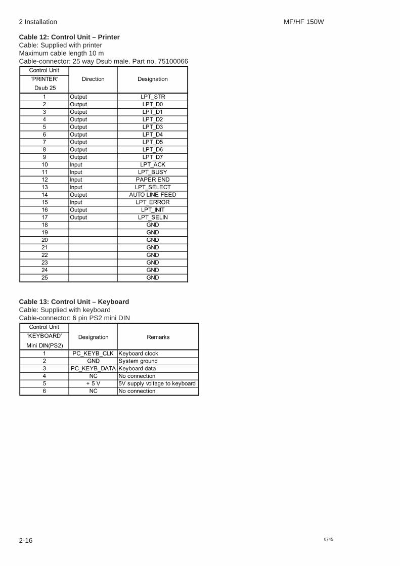
Cable 12: Control Unit – PrinterCable: Supplied with printerMaximum cable length 10 mCable-connector: 25 way Dsub male. Part no. 75100066
Control Unit'PRINTER' Direction Designation Dsub 25
1 Output LPT_STR2 Output LPT_D03 Output LPT_D14 Output LPT_D25 Output LPT_D36 Output LPT_D47 Output LPT_D58 Output LPT_D69 Output LPT_D710 Input LPT_ACK11 Input LPT_BUSY12 Input PAPER END13 Input LPT_SELECT14 Output AUTO LINE FEED15 Input LPT_ERROR16 Output LPT_INIT17 Output LPT_SELIN18 GND19 GND20 GND21 GND22 GND23 GND24 GND25 GND
Cable 13: Control Unit – KeyboardCable: Supplied with keyboardCable-connector: 6 pin PS2 mini DIN
Control Unit'KEYBOARD' Designation RemarksMini DIN(PS2)
1 PC_KEYB_CLK Keyboard clock2 GND System ground3 PC_KEYB_DATA Keyboard data4 NC No connection5 + 5 V 5V supply voltage to keyboard6 NC No connection
2 Installation MF/HF 150W
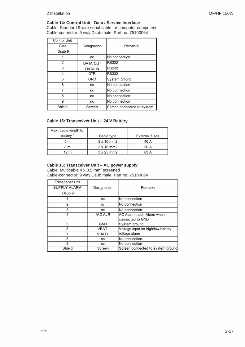
Cable 14: Control Unit - Data / Service InterfaceCable: Standard 9 wire serial cable for computer equipmentCable-connector: 9 way Dsub male. Part no. 75100064
Control UnitData Designation Remarks
Dsub 91 nc No connection2 DATA OUT RS2323 DATA IN RS2324 DTR RS2325 GND System ground6 nc No connection7 nc No connection8 nc No connection9 nc No connection
Shield Screen Screen connected to system
Cable 15: Transceiver Unit – 24 V Battery
Max. cable length to battery *
5 m 3 x 10 mm2 40 A8 m 3 x 16 mm2 50 A12 m 3 x 25 mm2 63 A
Cable type External fuses
Cable 16: Transceiver Unit – AC power supplyCable: Multicable 4 x 0.5 mm2 screenedCable-connector: 9 way Dsub male. Part no. 75100064
Transceiver Unit‘SUPPLY ALARM’ Designation Remarks
Dsub 91 nc No connection2 nc No connection3 nc No connection4 /AC ALR AC Alarm input. Alarm when
connected to GND5 GND System ground6 VBAT-7 VBAT+8 nc No connection9 nc No connection
Shield Screen Screen connected to system ground
Voltage input for high/low battery voltage alarm
0745 2-17

2 Installation MF/HF 150W
Cable 17: Transceiver Unit – TX Inhibit / RX MuteCable: Multicable 2 x 0.5 mm2 screenedMaximum cable length 3 mTransceiver Unit ‘SYS’ pins 4 and 5. Refer to ‘SYS’ table.
Cable 18: Transceiver Unit – Data modemCable: Multicable 9 x 0.5 mm2 screenedMaximum cable length 3 mCable-connector: 9 way Dsub male. Part no. 75100064
Transceiver Unit‘SYS’ Designation Remarks
Dsub 9Transmitter key input. Pulled up to +12 VActive when connected to GND
2 DATA OUT
3 DATA INAlso used for upload of software.Transmitter inhibit/RX mute input. Pulled up to +12 VActive when connected to GND
5 GND System groundSingle ended 600 ohms AF output 0 dBm in 600 ohms1.55 Vrms when unloadedRefers to system ground (GND)Single ended 600 ohms AF inputNominal level 0 dBmAccepts –15 dBm to +10 dBmRefers to system ground (GND)Low when TX keyedOC output, max. 50 mA, 32 V+12 V output Max. 100 mA, internally protected.
Shield Screen Screen connected to system ground
6 LINE OUT
7 LINE IN
1 EXT KEY
RS-232 port for remote control of frequency, mode and power level. T+Bus protocol, baud rate 2400 bps
4 TX INHIBIT MAIN RX MUTE
8 TX KEYED
9 +12 V
2-18 0745

2 Installation MF/HF 150W
2.8 Connector mounting instructions
9 and 25 way D-sub
Slide the plastic cover on thecable before the wires aresoldered to the pins.
After the pins are soldered; latchthe inner and outer shield into theconnector and snap in. Finallyslide the plastic cover over theshield and fit the two jack screwsinto the cover.
54321
9876
Contact arrangement(Viewed from solder side)
PL 25928.5mm
16mm 1.5mm
Coupling nut
Body
2-190745
2 Installation MF/HF 150W
2.9 Position and time information
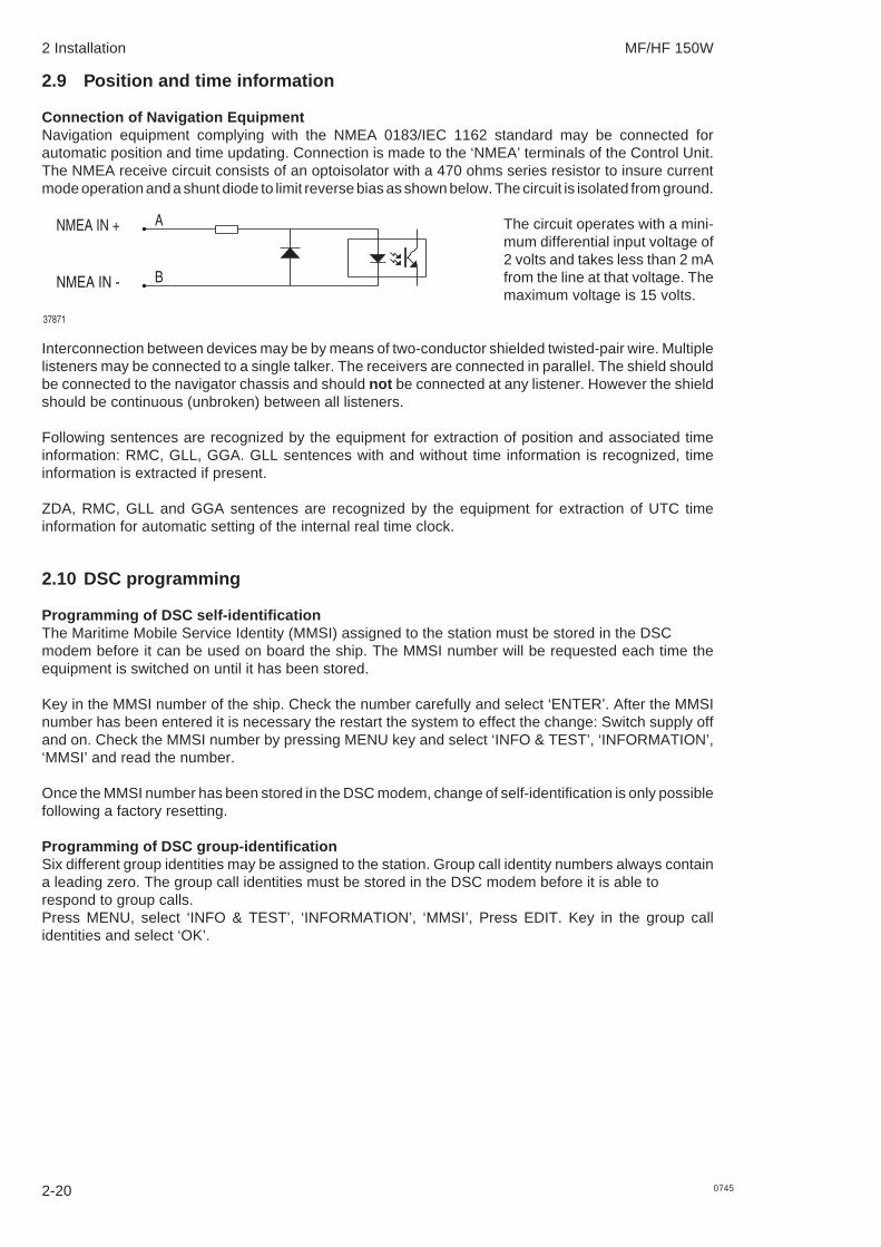
Connection of Navigation EquipmentNavigation equipment complying with the NMEA 0183/IEC 1162 standard may be connected forautomatic position and time updating. Connection is made to the ‘NMEA’ terminals of the Control Unit.The NMEA receive circuit consists of an optoisolator with a 470 ohms series resistor to insure currentmode operation and a shunt diode to limit reverse bias as shown below. The circuit is isolated from ground.
NMEA IN -
NMEA IN +
37871
A
B
The circuit operates with a mini-mum differential input voltage of2 volts and takes less than 2 mAfrom the line at that voltage. Themaximum voltage is 15 volts.
Interconnection between devices may be by means of two-conductor shielded twisted-pair wire. Multiplelisteners may be connected to a single talker. The receivers are connected in parallel. The shield shouldbe connected to the navigator chassis and should not be connected at any listener. However the shieldshould be continuous (unbroken) between all listeners.
Following sentences are recognized by the equipment for extraction of position and associated timeinformation: RMC, GLL, GGA. GLL sentences with and without time information is recognized, timeinformation is extracted if present.
ZDA, RMC, GLL and GGA sentences are recognized by the equipment for extraction of UTC timeinformation for automatic setting of the internal real time clock.
2.10 DSC programming
Programming of DSC self-identificationThe Maritime Mobile Service Identity (MMSI) assigned to the station must be stored in the DSCmodem before it can be used on board the ship. The MMSI number will be requested each time theequipment is switched on until it has been stored.
Key in the MMSI number of the ship. Check the number carefully and select ‘ENTER’. After the MMSInumber has been entered it is necessary the restart the system to effect the change: Switch supply offand on. Check the MMSI number by pressing MENU key and select ‘INFO & TEST’, ‘INFORMATION’,‘MMSI’ and read the number.
Once the MMSI number has been stored in the DSC modem, change of self-identification is only possiblefollowing a factory resetting.
Programming of DSC group-identificationSix different group identities may be assigned to the station. Group call identity numbers always containa leading zero. The group call identities must be stored in the DSC modem before it is able torespond to group calls.Press MENU, select ‘INFO & TEST’, ‘INFORMATION’, ‘MMSI’, Press EDIT. Key in the group callidentities and select ‘OK’.
2-20 0745

2 Installation MF/HF 150W
2.11 Battery alarm adjustmentConnect a voltmeter and an external power supply capable of delivering 1.0 A and adjustable up to 33V DC to the VBAT- and VBAT+ input of the SUPPLY ALARM connector on the Transceiver Unit. Openthe Transceiver Unit to gain access to the potentiometers on Control/Interconnection Module 122878.
Low voltage alarm1. Adjust the external power supply to the desired low voltage alarm level (22 – 24 V).2. Watch the Alarm LED.3. Now carefully turn the potentiometer marked ‘Batt. low adj.’ until the light in the Alarm LED just
disappears.Factory setting: 23.5 V
High voltage alarm1. Adjust the external power supply to the desired high voltage alarm level (27 – 32 V).2. Watch the Alarm LED.3. Now carefully turn the potentiometer marked ‘Batt. high adj.’ until the light in the Alarm LED just
disappears.Factory setting: 29.5 V
2.12 Options menu - setting up the systemTo open the Options menu, press MENU, select ‘SETUP’ and select ‘OPTIONS’ in the ‘SETUP’ menuand enter the access code,1,2,3,4.
Menu Submenu Level1
Submenu Level 2
EDITSelect band
CONFIGURATION
LANGUAGE
RX TEST
TX TEST SEND DOTS Send dot Pattern
SEND Y Send Y frequency (1615 Hz)
SEND B Send B frequency (1785 Hz)
FACTORY RESET
MMSI RESET
Turn off the radio!!!
Turn off the radio!!!
Enable/disable
OPTIONS TX BANDS Edit TX frequency band
Enable/disable serial output of decoded DSC calls for test purposes
LSB MODE REMOTE MODE BATT/ SUPPLY ALARM ATU INSTALLED RX MUTE MODE TX INHIBIT MODE AM TX MODE PRINT DSC
DSC Select language
Submenu Level 3 / Parameters
2-210812

2 Installation MF/HF 150W
Notes:
TX BANDS: Up to 16 frequency bands can be defined. Transmission is inhibited on frequenciesoutside the defined bands.
Factory pre-programmed: 1605.0 - 4000.0 kHz 4000.0 - 4438.0 kHz 6200.0 - 6525.0 kHz 8100.0 - 8815.0 kHz12230.0 - 13200.0 kHz16360.0 - 17410.0 kHz18780.0 - 18900.0 kHz19680.0 - 19800.0 kHz22000.0 - 22855.0 kHz25070.0 - 25210.0 kHz26100.0 - 26175.0 kHz
CONFIGURATION:LSB MODE: When enabled selection of LSB (Lower Side Band) is possible with the MODE key
on the front panel.Note: LSB mode is normally not allowed for marine equipment.Factory default setting: Disabled.
REMOTE MODE: When enabled selection of SSB REMOTE is possible with the MODE key on thefront panel, allowing remote control via the SYS connector of frequency, mode andpower level.Factory default setting: Disabled.
ATU INSTALLED: When enabled supply voltage and control signals for the ATU is present at the TX/RX connector. When disabled a 50 ohms antenna or dummy load may beconnected to TX/RX.Factory default setting: Enabled.
BATT /SUPPLY ALARM: When enabled the voltage at the VBAT input of the SUPPLY ALARM connector
is monitored and an alarm is given by the Control Unit if the voltage is outside theset range.Factory default setting: Disabled.
RX MUTE /TX INHIBIT: Select RX mute or TX inhibit to select functionality of input pin (SYS con – pin 4
on transceiver). When RX mute is selected this input will mute the receiver wheninput is pulled low. When TX Inhibit is selected this input will prevent keying thetransmitter when input is pulled low. Factory default setting: TX inhibit.
AM TX MODE: When AM TX is enabled it will be possible to transmit in AM mode with reducedpower.Note: AM TX mode is only allowed in connection with equipment typeapproved inaccordance with FCC.Factory default setting: Disabled.
PRINT DSC: When enabling this feature the DSC messages transmitted and received will beprinted out on the attached printer. Note that these DSC massage will still be storedin the DSC log.
DSC:LANGUAGE: Factory default setting: English.
RX TEST: When enabled decoded call sequences are routed to the RS-232 port of the SYSconnector. Baud rate: 2400 baud. Parity/data bits: Odd/8.Factory default setting: Disabled.
TX TEST: For generation of continuous B or Y signal and dot pattern. DSC mode must beselected.2-22 0812

2 Installation MF/HF 150W
FACTORY RESET: Choosing this option will reset all user programmable settings to the factory defaultsettings. MMSI will also be reset.
MMSI RESET: Choosing this option will only reset the MMSI number. Input new MMSI numberafter power up.
2.13 Factory resetting / MMSI resettingFactory resetting and MMSI resetting is done on the Control Unit via the options menu.To enter the options menu press MENU, select SETUP and finally select OPTIONS.Then enter the access code 1-2-3-4.
Factory resettingSelect FACTORY RESETThe Control Unit will prompt for power off of the equipment.When powered up again the System is in a state as described below.
The Factory Reset puts the System back to the default state originally set at the factory.The chapters 2.10, 2.11 and 2.12 must therefore be repeated in order to restore the System settingsbefore the Factory Reset.The MMSI number must also be entered.The Factory Reset removes configuration keys regarding Telex Operation and 6 ch scanning DSCWatch Receiver if any of these keys were enabled.Therefore it is necessary to carry out section 2.14 and 2.15, if the options have been installed before thefactory reset.
MMSI resettingSelect MMSI RESETThe Control Unit will prompt for power off.When powered up again the System is in a state as described below.
The MMSI reset only clears the MMSI number and when the system is powered up again the MMSInumber us the only parameter which has to be reprogrammed.
Note: The System serial number is not affected by either the Factory Reset or the MMSI reset.
2.14 Enabling the 6 ch scanning DSC Watch ReceiverFor the MF/HF product a 6 ch scanning DSC Watch Receiver option is available. The option is enabledby entering a 10-digit pin code into the transceiver. The pin code is uniquely matched to the serial numberof the transceiver.Once in possession of the required pin code the 6 ch scanning option is enabled from the menu pointWatch Receiver in the Config Status menu. To enter the Config Status menu, press MENU, select SETUPand finally select CONFIG STATUS. The 10-digit code is then entered from the control unit keypad.For further information refer to the user manual.When the pin code has been entered once, the feature remains permanently enabled.Concerning setting up the scanning sequence refer to the user manual.
IMPORTANT:Remember to write down the transceiver serial number and the corresponding 10-digit pin code in thetable below.The table content is needed in connection with Service/Maintenance, when the system has beenFactory Reset or the Control/Intercon module 60-122879 has been replaced.In conjunction with Factory Reset or replacement of Control/Intercon module 60-122879 the6 ch scanning DSC Watch Receiver option need to be enabled again as described above.
2-230812

2 Installation MF/HF 150W
2.15 Enabling the Telex operationFor the MF/HF product a Telex operation option is available. The option is enabled by entering a 10-digitpin code into the transceiver. The pin code is uniquely matched to the serial number of the transceiver.Once in possession of the required pin code the Telex option is enabled from the menu pointTelex in the Config Status menu. To enter the Config Status menu, press MENU, select SETUP and finallyselect CONFIG STATUS.The 10-digit code is entered from the control unit keypad.For further information refer to the user manual.When the pin code has been entered once, this feature remains permanently enabled.
IMPORTANT:Remember to write down the transceiver serial number and the corresponding 10-digit pin code in thetable below.The table content is needed in connection with service/maintenance, when the system has beenFactory Reset or the Control/Intercon module 60-122879 has been replaced.In conjunction with Factory Reset or replacement of Control/Intercon module 60-122879 theTelex operation option need to be enabled again as described above.
Serial number *:
6 ch scanning DSC Watch Receiver pin code:
Telex Operation pin code:
* Please f ind typelabel w ith serial number on transceiver side
2.16 Telex operationFor the MF/HF products a telex operation option is available. The telex operation option is enabled byentering of a pin-code (key) into the MF/HF transceiver. This pin code is uniquely matched to the serialnumber of the MF/HF transceiver, i.e. one specific pin code will enable the telex operation option in onespecific MF/HF transceiver only.Once in possession of the required pin code the telex operation option is enabled from the menu pointtelex operation Code in the System Setup menu. The 10-digit pin code is entered from the transceiverkeypad.When the pin code has been entered and the telex operation option enabled, the telex operation featureremains permanently available for selection.
For details on how to obtain the telex operation feature for your SAILOR CU5100 MF/HF transceiver,contact your local Thrane & Thrane representative.
2.16.1 GMDSS Radiotelex terminalThe GMDSS Radiotelex Terminal is an option used for handling transmission/reception of telexmessages over radio. The terminal consists of a printer and a keyboard, connected to the transceivercontrol unit which provides the interface to the DSC/telex modem located in the transceiver unit. Thekeyboard is equipped with an affixed template for function keys and indicator lamps.
The GMDSS Radiotelex Terminal is designed in accordance with relevant IMO, ITU and ETSIrecommendation/specifications and has been approved for shipboard installations to be operating withinthe Global Maritime Distress and Safety System.
It supports world-wide ship-to-ship, shore-to-ship and ship-to-shore communication by utilizing theradiotelex protocols described in ITU- Rec. 625 to overcome the deficiencies of the HF medium. In caseof two-way communication an ARQ (Automatic Repetition reQuest) algorithm for error correction is thusused, and when sending to more than one station an FEC (Forward Error Correction) algorithm is used.
2-24 0812

2 Installation MF/HF 150W
CouplerHF AerialATU5215
CU5100
Handset
Data ModemAP5065 Option
Option
99-126498A
MF/HF
Power Supply
TT-3606E
TT-3601E
H1252B
DSC Watch receiver150W MF with 6 ch. Scanning
TU5160
Telex option 2
TT-3601E
H1252B
Telex option 1
MF/HF DSC Telex Aerial
5070
2.16.2 Simple telex operation
2.16.2.1 Installation and Initial Set-up
PrinterThe terminal uses an OKI Microline 280 parallel interface dot-matrix printer with roll paper stand, pleaserefer to the operation guide delivered with the printer. The printer should be connected to the printer socketat the rear of the control unit by means of the parallel interface cable included with the printer. The printeris equipped with a special firmware which allows the paper to be scrolled up so the current line can beread in printing pauses, and scrolled back down when printing continues. The firmware version can bechecked by performing a selftest: Disconnect the parallel interface cable. Press the LF (line-feed) and theSelect button while switching the printer on. When light comes on in the indicator lamps, release thebuttons. The printer version is now printed followed by a test print-out. The version must be: F/W 03.10Also make sure the printer firmware is configured for radio telex. This is shown in the snapshot below,where “MEI E1” indicates configuration for radio telex.
KeyboardThe keyboard is a Cherry 1800 PC/AT compatible keyboard. The self-adhesive keyboard templatedelivered with the equipment must be mounted on the keyboard: Remove the protective paper. Carefullyplace the template around the function keys and indicator lamps so the latter are fully visible.
2-250812

2 Installation MF/HF 150W
Modem Set-upModem set-up mode is selected automatically when selecting telex mode on if no call codes are valid orif the answer back string is not valid. To change a valid set-up, a factory reset of the modem must beperformed.
When entering telex mode after a factory reset the 5-digit call code, may then be entered. The MMSInumber from the control unit will be printed, but cannot be changed. The answer back string allocated tothe station may then be entered. To leave a setting unchanged just press ‘¬ Enter’, otherwise key in a newsetting and press ‘¬ Enter’. The next item is then printed. After the last item follows:Accept settings (Y/N)?
The process may be repeated if ‘N’ is pressed; the modem set-up mode is left if ‘Y’ is pressed.
The answer back, which should be entered above is combined by the 5-digit call code or MMSI number,the abbreviated ID and an “x” e.g.:
12345 abcd x or 123456789 abcd x
2.17 Final installation checkFor operation of the equipment please refer to the User Manual.
Check the hardware configuration of the transceiver by selecting FUNC and the ‘INFO & TEST’,‘INFORMATION’ ‘HW VERSION’ menu items, in particular check that the Antenna Tuning Unit isrecognized, if installed.
Perform a Self Test of the transceiver by selecting FUNC and the ‘INFO & TEST’, ‘CHECK’, ‘SELFTEST’menu items. The self test is performed automatically and is used for verification of all functions. Checkthe transmitter in all marine bands.
The Antenna Tuning Unit will tune automatically to the antenna first time the equipment is keyed on anew frequency or when the TUNE button is pressed. During the tune sequence and normal transmissionall transmitter circuits are monitored to ensure safe operating conditions. If transmission conditions arebad ( bad antenna installation, high temperatures, etc. ) the transmitted power will be reduced to a safelimit. If the transmission condition is improved automatic recovery to full power takes place.
The protection can be investigated by selecting FUNC and the ‘INFO & TEST’, ‘CHECK’, ‘TX PROTEC-TION’ menu items. The displayed protection code(s) is described in the Service chapter of this manual.If a GPS is connected, check position and time in the DSC Status display.If time is not contained in the NMEA sentences the time of position is indicated as —:—. In this case checkif the GPS output setting can be changed to allow time information. Otherwise UTC time must be enteredmanually each time the transceiver is switched on.
Send a DSC test call to the appropriate coast station. The acknowledgement from the coast station isreceived by the 2187.5 kHz watch receiver if the call was sent on that frequency. If the call is sent on HFonly the audio signal output from the 2187.5 kHz watch receiver should be checked by selecting FUNCand the ‘INFO & TEST’, ‘MONITOR’, ‘WR AUDIO’ menu items.
2-26 0745

3-1
MF/HF 150W
0745
3 Technical description
3.1 Control UnitThe Control Unit consists of a main module 60-122876 and a MMI module 60-122877.
The main module consists of the digital part, i.e. the microprocessor, program FLASH PROM,configuration FLASH PROM, RAM, ScanBus data communication driver, SPARC-Bus driver, Printerinterface, Keyboard interface and data terminal interface.The main module also consists of an analog part, i.e. the voltage regulators, the analog interface circuitsand the analog output drivers (audio and light). The main module supports a build-in speaker and theconnectivity of an external 8 ohm speaker.
The MMI module contains the graphical TFT color display (240x320 dots), the display controller, keyboardinterface and encoders for volume and rotary knob.
3.2 Transceiver UnitBlock diagram page 3-3, Interconnection diagram page 3-4.
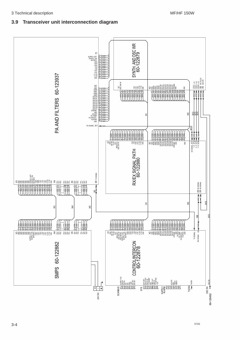
The Transceiver Unit consists of five modules. Three modules located in the base part of the unit: a controland interconnection module, a receiver/exciter signal path module, and a synthesizer and DSC RXmodule including master oscillator, and two modules are located in the door part of the unit: a poweramplifier module including filter bank and a switched mode power supply. The main wiring is by ribboncables with Micro MaTch connectors. RF signals are routed in coaxial cables using Taico, MCX and BNCconnectors.
3.3 Control/Intercon module 60-122878The Control/Intercon module performs the digital and analogue control of the transceiver functionsrequested by the Control Unit and contains interconnection circuits. The central part is the CPU. Theprogram software is contained in Flash PROM. A separate Flash PROM holds the configurationparameters. The processor communicates with the CU via the CAN interface, with auxiliary equipmentvia an RS-232 interface and the ATU via a modem circuit. Internal communication is via the TU Bus. Thetransmitter is monitored via the PA Peak, Filter Peak and Filter Average detectors. An adjustable opto-isolated battery detector circuit monitors the battery voltage at the Supply Alarm connector and triggersan alarm when outside the set range. The CPU also performs DSC modulator and dual DSC demodulatorfunctions. The modulator output is through a transversal filter. Audio switching allows loop back test.Audio circuits convert between unbalanced and balanced lines used by the ScanBus.
3.4 Synth. and DSC WR module 60-122879The Synthesiser part includes Master oscillator, dividers, 3.LO PLL and VCO, 2.LO filters and multiplierand 1.LO fractional N system as well as both 1. and 2. DSC LO PLL and VCO. The Master oscillatorgenerates a 17.8176MHz reference signal which is distributed to the local Synthesizer LO sub-circuits.The appropriate frequencies for the MF/HF transceiver are then generated.
The DSC Watch receiver is built up as a Double Super Heterodyne Receiver using Intermediatefrequencies of 30.155 MHz and 455 KHz.After frequency conversion to 455 KHz the signal is fed to 455 KHz IF2 AGC amplifier before led to finaldetection / conversion to 1700 Hz.The Signal is filtered out by 1700 Hz Audio filter and afterwards led to limiting amplifier thus creating theDSC output for further processing.The Receiver Signal Path also includes antenna supply and receiver protection circuitry.A RF splitter divides the DSC antenna signal between the Watch Receiver and the Main Receiver, whichuses the signal in telex mode.
The Synthesizer used for the Watch Receiver consists of the following sub circuits:
3 Technical description MF/HF 150W
3-2 0745
· An integer type PLL is used for creating the DSC LO1 signal. The PLL resolution is 2 KHz and afterdivision by 4 the final DSC LO1 resolution is 500 Hz. Three separate VCO´ s are used for coveringthe necessary frequency range. A 14.85 MHz TCXO is used for reference for the PLL.
· A doubler Circuit submitted to the 14,85 MHz reference signal is used for DSC LO2 signal thuscreating 29.70 MHz.
· A 14.6144 MHz TCXO divided by 32 thus creating 456.7 KHz is used for DSC LO3 signal.
3.5 RX/EX signal path module 60-122880The RX signal path includes protection, pre-selection, mixers, IF amplifiers, filter bank, demodulator,squelch and audio. The RX signal path has Automatic Gain Control. The RX signal path performs thehandling of the received antenna signal and delivers an AF signal, via the Control/Intercon module wherethe AF signal is converted from an unbalanced to a balanced signal, to the Control Unit.
The RX signal path also includes a DSC receiver signal path, which uses the MF/HF signal path, until thelast down conversion. DSC part includes a mixer, base band filter and hard limiter. During DSC reception,the DSC part overrules the normal MF/HF reception.
The EX signal path includes AF compressor, modulator, filter bank, mixers and EX output amplifiers. TheEX signal path has Automatic Loop Control. The EX signal path generates the modulated RF signal,adjusted to correct level - ALC adjusted signal, to the Power Amplifier.
The RX / EX signal path is controlled by the Control/Intercon module and receives its injection signal fromthe Synth./DSC WR module.
3.6 PA and Filters module 60-122881The PA and Filters module includes PA drivers, PA-stage, protection circuits, bias circuits, key circuit andseven low-pass filters with relays and relay drivers. The PA and Filters receives the modulated RF inputsignal from the RX/EX Signal Path and delivers the amplified and filtered output signal to the TX/RXconnector via a receive/transmit relay on the Control/Intercon module.
The low-pass filters removes the unwanted harmonic frequencies from the PA signal. The Filpeak andPAprotec outputs are monitoring signals for the Control/Intercon module. The driver and final poweramplifier stages are galvanically isolated on input and output as they are supplied directly from the 24 VDC input. The selection of low-pass filter is controlled by the Control/Intercon module.
The PA filters cover the frequency ranges:1.6 – 2.3 MHz2.3 – 3.05 MHz3.05 – 4.5 MHz4.5 – 8.8 MHz8.8 – 16.81 MHz16.81 – 19.0 MHz19 – 30.0 MHz
3.7 SMPS module 60-123937The Switched Mode Power Supply supplies the low power circuits of the equipment with the variousstabilized voltages required, and provides galvanic isolation from the supply source. The equipment issupplied from a 21.6 – 31.2 V DC power source. The module also carries the input filter and PA supplyoutput which is not galvanically isolated.
The power supply converts the incoming voltage to 7.5 V, +15 V, -15, and 25 V. The SMPS is switchedon from the Control Unit via the Scanbus SUPPLY ON wire and switched off under software control viathe SUPPLY ON/OFF connection from the Control/Intercon module. The DC supply voltage is sensed bya BAT INFO detector circuit and fed to the Control/Intercon module for automatic RF output poweradjustment.

3 Technical description MF/HF 150W
0745 3-3
3.8 Transceiver unit block diagram
AF
Sw
itch
SM
PS
60
-12
28
82
Filte
r
CP
U
CO
NT
RO
L/I
NT
ER
CO
N 6
0-1
22
87
8
TX
/RX
DS
C R
X
Modem
TU
-AT
U
Sw
itch
TX
/RX
SC
AN
BU
S
ALA
RM
SU
PP
LY
SY
S
60
0 O
hm
60
0 O
hm
Inte
rfa
ce
De
tecto
r
TX
In
hib
itT
X K
ey &
RS
-232
Convert
er
Convert
er
RX
AF
AF
Am
p.
AF
Sw
itch
AF
Am
p.
CA
N
TX
AF
24
V D
C
DS
C W
R A
F
DS
C R
X A
F
RX
AF
Mo
de
Supply
Po
we
r
Sw
itch
ed
+ 2
5 V
+ 1
5 V
+ 7
.5 V
- 15 V
RX
/EX
SIG
NA
L P
AT
H 6
0-1
22880
RX
SIG
NA
L
TX
SIG
NA
L
Sele
cto
rP
re-
EX
SIG
NA
L
Circu
itP
rote
ctio
nD
SC
WR
AF
SY
NT
H. A
ND
DS
C W
R 6
0-1
22879
AG
C a
mp.
IF2
DS
C A
Ffilte
r
3. LO
Filte
ra
nd
Ga
in
45
MH
z
Com
pres
sor
TX
AF
455 k
Hz
Bank
Filte
r
Mo
du
lato
r
DS
C R
X A
FD
SC
Filt
er
Am
p.
1700 H
z
RX
AF
ge
ne
rato
rA
GC
Div
iders
and
PA
AN
D F
ILT
ER
S 6
0-1
23
93
7
LP
Filt
ers
99
-12
64
91
Dem
odul
ator
24
V D
C t
o P
A
Sw
itch
Ant.
OC
XO
VC
OP
LL
2. LO
Filt
er
X5
Filt
er
1. LO
Ba
nd
AP
IP
LL
sele
ct
co
rr.
Lo
op
am
pl.
VC
OS
am
ple
ho
ld
Ram
p
gen.
DA
CP
rescale
r
Supply
An
ten
na
Filt
er
Fro
nte
nd
by 4
Div
ide
32 -
46 M
Hz
VC
O
PL
L
14.8
500
MH
zV
CT
CX
O
X22
9.7
MH
z
by 3
2D
ivid
e456.7
kH
z
14.6
641
MH
zV
CT
CX
O
filte
rin
gIF
1 A
mplif
ier
&filte
rin
gIF
2 A
mplif
ier
&
IF1=
30.1
55M
Hz
IF2
=4
55
kHz
17
00
Hz
Lim
ite
rH
ard
3 Technical description MF/HF 150W
3-4
3.9 Transceiver unit interconnection diagram
99
-12
64
92
10
DA
TA
4
DS
C R
X
9
TX
/RX
VB
AT
-
GN
D
VB
AT
+
AC
ALR
8765432
RX
SIG
NA
L
TX
SIG
NA
L X9
PA
PR
OT
EC
18 20
19
GN
D
FIL
PE
AK
12
15
14
17
16
13
ST
RO
BE
GN
D
PA
KE
Y
PA
TE
MP
DA
TA
6
DA
TA
5
DA
TA
7
113T
X A
F
60-1
22878
CO
NT
RO
L/I
NT
ER
CO
N
LIN
E I
N7
+1
2V
TX
KE
YE
D
198
GN
D
TX
IN
HIB
IT
DA
TA
IN
DA
TA
OU
T
EX
T K
EY
LIN
E O
UT
3 654215
+2
5V
GN
D
AF
-
RX
AF
-
RX
AF
+9876
SU
PP
LY
ON
AF
+
DA
TA
-
DA
TA
+
1 432
19
+7
.5V
2A
DR
03 654 987
DA
TA
0
DA
TA
3
DA
TA
2
DA
TA
1
AD
R1
AD
R3
AD
R2
20
GN
D
+7
.5V
GN
D
1
DS
C W
R A
F
DS
C R
X A
F
SU
PP
LY
ON
SU
PP
LY
OF
F
11+
25
V
13
12
16
15
18
17
14
-15
V
+1
5V
+1
5V
+2
5V
+2
5V
-15
V
54 876 10
9
BA
TIN
FO
AG
C
MG
C/A
LC
2G
ND
RX
AF
120
PA
-
PA
+
1 2 18
19
PA
-
PA
-
PA
-
PA
-
PA
-
5
SM
PS
60-1
22882
GN
D
PA
+
19
18 20
PA
+
PA
-
PA
+
PA
+
1 2P
A+
PA
+
SU
PP
LY
ON
SU
PP
LY
OF
F
+2
5V
20
+1
5V
+7
.5V
+7
.5V
+1
5V
+2
5V
-15
V
-15
V
17
19
18
14
13
16
15
+2
5V
BA
TIN
FO
GN
D
GN
D
GN
D
9 1110
12
8762G
ND
GN
D
GN
D
GN
D
1 43
10
DA
TA
41
0D
AT
A4
1.
LO
3.
LO
2. LO
EX
SIG
NA
L
RX
SIG
NA
L
18 20
19
GN
D
12
11 15
14
17
16
13
ST
RO
BE
GN
D
DA
TA
7
DA
TA
6
DA
TA
5
1.
LO
RX
TE
LE
X
2. LO
3.
LO
18 20
19
GN
D
GN
D
ST
RO
BE
DA
TA
7
DA
TA
6
DA
TA
5
14
15
17
16
12
11 13
DS
C R
X A
F
RX
/EX
SIG
NA
L P
AT
H60-1
22880
20
18
19
1 2
TX
SIG
NA
L
PA
+
PA
-
PA
-
PA
-
PA
-
PA
-
PA
-
3T
X A
F
19
+7
.5V
2A
DR
03 654 987
DA
TA
0
DA
TA
3
DA
TA
2
DA
TA
1
AD
R1
AD
R3
AD
R2
20
GN
D
+7
.5V
GN
D
111
+1
5V
+1
5V
-15
V
-15
V15
16
18
17
13
12
14
AG
C
MG
C/A
LC
7 10
9854 6
19
2A
DR
0
DA
TA
0
AD
R3
AD
R2
AD
R1
DA
TA
3
DA
TA
2
DA
TA
1
6 9873 54
+7
.5V
1G
ND
20
GN
D
11
+1
5V
+7
.5V
15
-15
V16
18
17
+1
5V
13
12
14
DS
C W
R A
F7 10
98
EX SIGNAL
2
GN
D
RX
AF
1
5 20
19
18
1 217
19
18 20
14
13
16
15
9 1110
12
876
GN
D
PA
+
PA
+
PA
-
PA
+
PA
+
PA
+
PA
+
+2
5V
+1
5V
+1
5V
+7
.5V
+7
.5V
+2
5V
-15
V
-15
V
SU
PP
LY
ON
SU
PP
LY
OF
F
+2
5V
BA
TIN
FO
GN
D
GN
D
GN
D
1 2 43G
ND
GN
D
GN
D
GN
D
PA
AN
D F
ILT
ER
S6
0-1
23
93
7
60
-12
28
79
SY
NT
H.
AN
D D
SC
WR
GND
SUPPLY ON
SUPPLY OFF
BATINFO
-15V
+7.5V
+7.5V
+15V
+15V
+25V
+25V
-15V
+25V
PA KEY
PA TEMP
FILPEAK
PA PROTEC
GND
19
20
17
18
DATA1
DATA2
DATA3
DATA0
DATA5
DATA6
DATA7
STROBE
DATA4
6
GND
14
16
15
13
12
9
11
10
7
8
1
ADR1
ADR2
ADR3
GND
ADR0
5
4
3
2
15
18
20
19
17
16
13
14
12
10
11
9
7
8
RX
SIG
NA
L
DS
C R
X
DS
C R
X
TX
/RX
X5
SC
AN
BU
S
ALA
RM
SU
PP
LY
24
V D
C
SY
S
X2X1
X4
X3
W10
W9
X9
W2
W13
W12
W1
4
X12
X1
4
X1
3
X1
1
W2
X12
X8
X1
3
X1
4
X5
W1
W5
X8
X8
X2
W1
X2
X11
X1
X1
W4
W3
X4
X3
X1
X2
W11
X9
X5
W1
6
+ -
0745

3 Technical description MF/HF 150W
3-50745
3.10 Antenna Tuning Unit
ATU module 60-122883The ATU module comprises tuning network, measuring system and micro-controller circuits. The ATUmodule matches the impedance of the antenna to 50 ohm in order to gain the best possible SWR. TheATU module communicates tuning process and frequency information with the transceiver unit. Thetuning network consists of Capacitor Bank 1, Capacitor Bank 2, and an Inductor Bank. With these it ispossible to form either an L-network or a p-network. The capacitor banks and inductor bank are built upby binary related capacitors respectively binary related coils. The setting of capacitance and inductanceis accomplished by relays. A current detector at the antenna output terminal is used for measuring theantenna current for display at the Control Unit. To prevent overload of the relays, current detectors areincorporated in the Inductor Bank and in Capacitor Bank 2 and information fed back to the transceiverunit to decrease the output power if maximum permissible current is exceeded. To prevent overheatinga temperature sensor is incorporated which at excessive temperatures commands the transceiver toreduce the output power.
In receive mode an RX-Amplifier included in the Antenna Tuning Unit will be inserted, to improve thesensitivity of the system. It is possible to select the sensitivity in the steps OFF and NORMAL from theControl Unit.
3.11 Antenna Tuning Unit block diagram
Tune Att.
4 dB
Directional
Coupler
26dB
VwVref
Micro Prosessor
L-bank L-bank
Tuning circuitRX/TX/
ATU/COM
24V DC
Rx
Amp
Antenna
Connector
Horn
Antenna
Temperature
sensor
Modem filter
Demodulator Modulator
RF filter
24V
5V
regulator
to relays
to digital
circuits
13/24V
SMPS
to relays
24V in Rx & Tune Tx
13V in Tx
DC regulators
IL detectorIant. detector
Ic
detector
CB2
control by
uP
rx
tx
control by
uP
current
detectors
RX amplifier
Phase &
Voltage
Detectors
control
banks
CB1
control
Rx/Tx
High Pass Filter
40637
regulator
12V
3 Technical description MF/HF 150W
3-6 0745
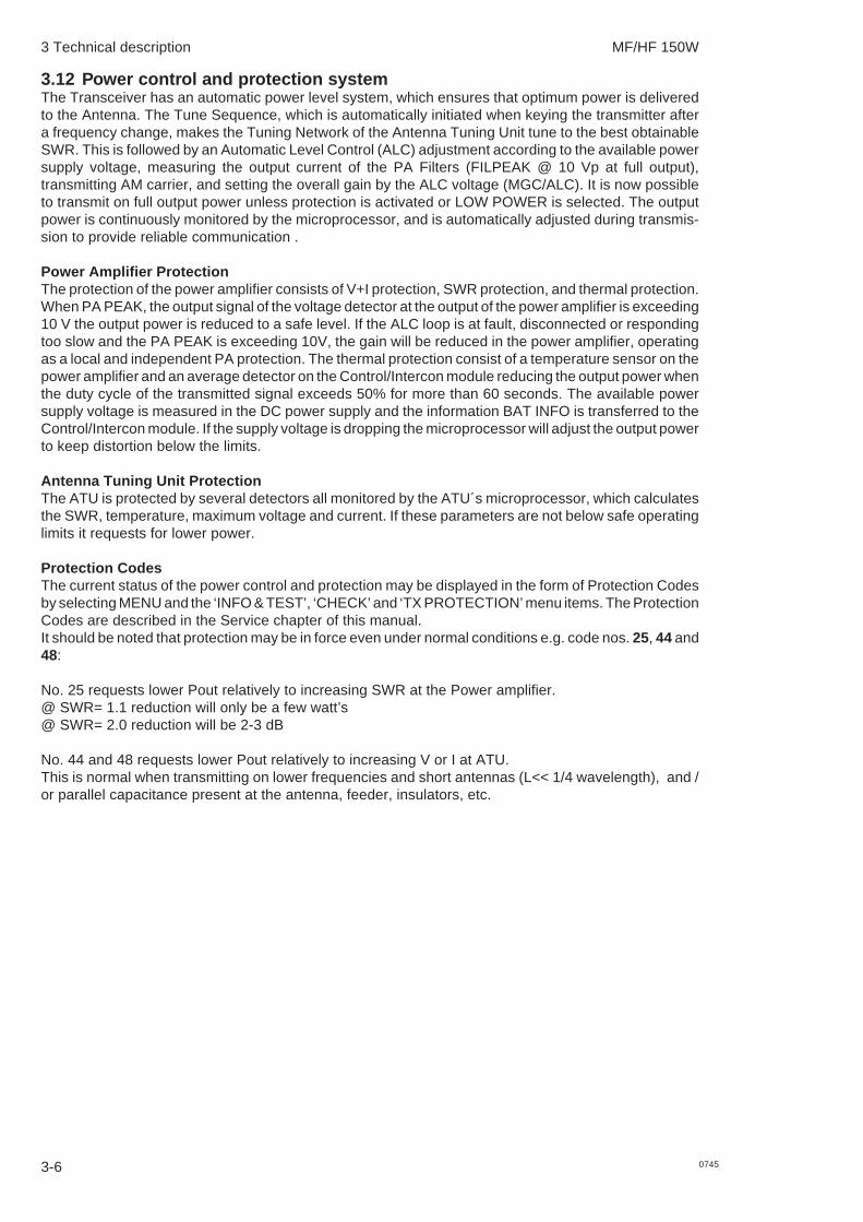
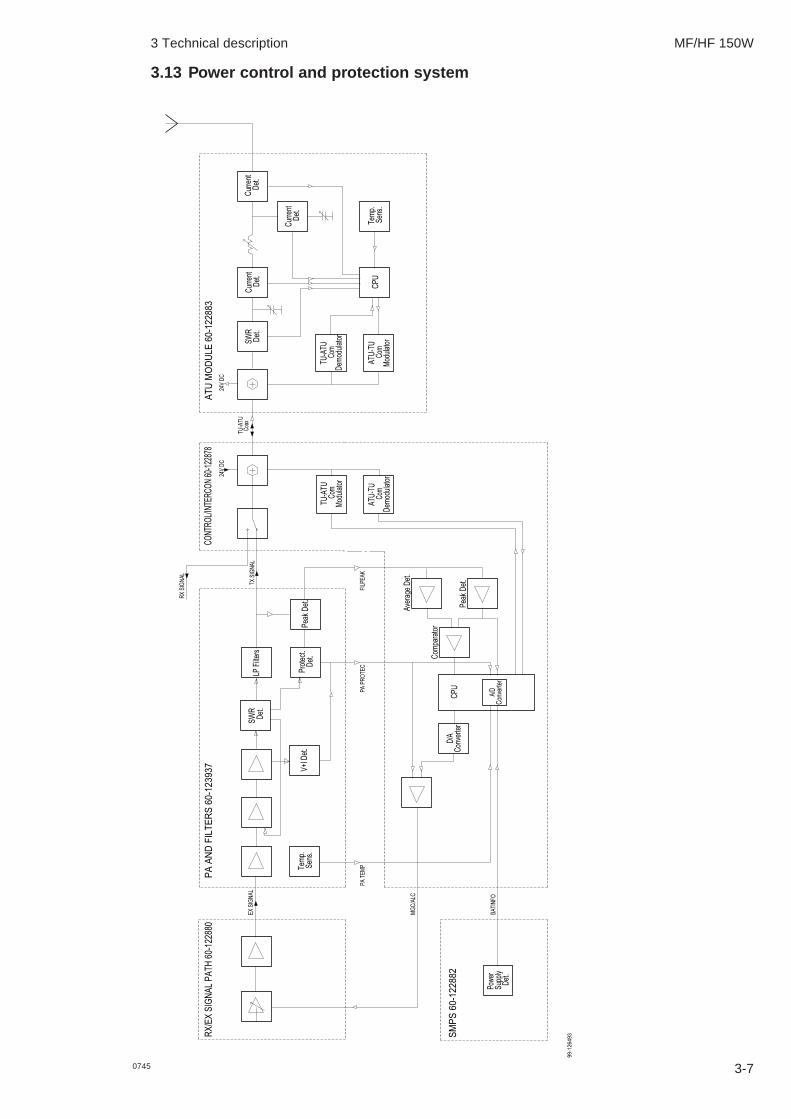
3.12 Power control and protection systemThe Transceiver has an automatic power level system, which ensures that optimum power is deliveredto the Antenna. The Tune Sequence, which is automatically initiated when keying the transmitter aftera frequency change, makes the Tuning Network of the Antenna Tuning Unit tune to the best obtainableSWR. This is followed by an Automatic Level Control (ALC) adjustment according to the available powersupply voltage, measuring the output current of the PA Filters (FILPEAK @ 10 Vp at full output),transmitting AM carrier, and setting the overall gain by the ALC voltage (MGC/ALC). It is now possibleto transmit on full output power unless protection is activated or LOW POWER is selected. The outputpower is continuously monitored by the microprocessor, and is automatically adjusted during transmis-sion to provide reliable communication .
Power Amplifier ProtectionThe protection of the power amplifier consists of V+I protection, SWR protection, and thermal protection.When PA PEAK, the output signal of the voltage detector at the output of the power amplifier is exceeding10 V the output power is reduced to a safe level. If the ALC loop is at fault, disconnected or respondingtoo slow and the PA PEAK is exceeding 10V, the gain will be reduced in the power amplifier, operatingas a local and independent PA protection. The thermal protection consist of a temperature sensor on thepower amplifier and an average detector on the Control/Intercon module reducing the output power whenthe duty cycle of the transmitted signal exceeds 50% for more than 60 seconds. The available powersupply voltage is measured in the DC power supply and the information BAT INFO is transferred to theControl/Intercon module. If the supply voltage is dropping the microprocessor will adjust the output powerto keep distortion below the limits.
Antenna Tuning Unit ProtectionThe ATU is protected by several detectors all monitored by the ATU´s microprocessor, which calculatesthe SWR, temperature, maximum voltage and current. If these parameters are not below safe operatinglimits it requests for lower power.
Protection CodesThe current status of the power control and protection may be displayed in the form of Protection Codesby selecting MENU and the ‘INFO & TEST’, ‘CHECK’ and ‘TX PROTECTION’ menu items. The ProtectionCodes are described in the Service chapter of this manual.It should be noted that protection may be in force even under normal conditions e.g. code nos. 25, 44 and48:
No. 25 requests lower Pout relatively to increasing SWR at the Power amplifier.@ SWR= 1.1 reduction will only be a few watt’s@ SWR= 2.0 reduction will be 2-3 dB
No. 44 and 48 requests lower Pout relatively to increasing V or I at ATU.This is normal when transmitting on lower frequencies and short antennas (L<< 1/4 wavelength), and /or parallel capacitance present at the antenna, feeder, insulators, etc.
3 Technical description MF/HF 150W
3-70745
3.13 Power control and protection system
99
-12
64
93
Det.
Supply
Po
we
r
SM
PS
60-1
22882
BA
TIN
FO
MG
C/A
LC
PA
TE
MP
Convert
er
D/A
RX
/EX
SIG
NA
L P
AT
H 6
0-1
22
88
0P
A A
ND
FIL
TE
RS
60-1
23937
Sens.
Te
mp
.
EX
SIG
NA
L
V+
I D
et.
AT
U M
OD
UL
E 6
0-1
22
88
3
De
t.S
WR
De
mo
du
lato
rC
omC
om
Co
nve
rte
rA
/D
CP
U
Com
para
tor
PA
PR
OT
EC
Pe
ak D
et.
Ave
rag
e D
et.
FIL
PE
AK
De
mo
du
lato
r
AT
U-T
UC
om
Mo
du
lato
r
AT
U-T
U
Mo
du
lato
rC
om
CO
NT
RO
L/IN
TE
RC
ON
60-
1228
78
Pe
ak D
et.
De
t.P
rote
ct.
LP
Filt
ers
TX
SIG
NA
L
RX
SIG
NA
L
TU
-AT
U
TU
-AT
U
24V
DC
TU
-AT
U
24V
DC
Coax
CP
US
ens.
Te
mp
.
Cu
rre
nt
De
t.
De
t.C
urr
en
t
Cu
rre
nt
De
t.S
WR
De
t.

4-1
MF/HF 150W
0745
4 Service
4.1 Preventive maintenanceDue to the modern design of the transceiver preventive maintenance can be reduced to a minimumprovided the equipment is correctly installed. To ensure maximum performance and minimum repairtrouble we recommend you to follow the below stated headlines for preventive maintenance.
1. The condition of the battery should be checked at frequent intervals. The battery must always befully charged and should be topped up frequently with distilled water (liquid should be 5 to 10 mmabove the plates).
2. Check the condition of antenna installation, ground connection and cables at regular intervals.
3. Keep antenna feed-through insulators clean and dry.
4. Ensure that no objects are obstructing the free airflow through the cooling fins of the TransceiverUnit and keep the units free of dust accumulation to prevent overheating.
5. For cleaning use a damp cloth. Sticky dirt may be removed using a cloth with a weak soap solution.Wipe off with a clean cloth.
4.2 Realignment of master oscillatorThe master oscillator determines the exact transmit and receive frequencies of the equipment. Alloscillators age very slowly with time, typically with the highest drift rate the first year, approaching zerodrift after some years. Adjustment should be performed by a qualified technician with the necessary testequipment at his disposal.
1. Measuring Equipment:
Frequency Counter: Frequency range 100 MHzInput impedance = 1 MohmSensitivity at least 0.2 VrmsAccuracy better than 0.01ppm
2. Preparations:
2.1 Switch on the power at least 30 minutes before adjustment.2.2 Open the front of the Transceiver Unit.2.3 Locate X13 on SYNTH.AND DSC WR module 60-122879 carrying the 2. Local Oscillator
signal from the synthesizer to the RX/EX Signal Path. Connect the frequency counter probeto the inner conductor of the X13 socket on the synthesizer.
2.4 The ambient temperature should be within 10 to 30 deg. Celsius. Do not adjust the MasterOscillator shortly after long keying sequences of the transmitter. Be sure that thermalequilibrium has been reached before adjustment.
3. Realignment of Master Oscillator:
3.1 Locate the Master Oscillator adjustment hole in the metal cover over SYNTH.AND DSC WRmodule 60-122879. Use a small screwdriver to gently adjust the frequency.
3.2 Adjust the frequency as close as possible to 44.544 000 MHz.Adjustment tolerance +/-1Hz.
3.3 Remove the counter probe and refit the front of the Transceiver Unit.

4 Service MF/HF 150W
4-2 0745
4.3 Software updateCode and configuration software are placed in flash memory. Consequently it is not necessary todismantle the units in order to update the software; a PC link must be used.
4.3.1 SetupIn order to perform a software update, a PC with a communication program (e.g. Procomm Plus orHyperTerminal) and a communication cable are required.If the Hyper Terminal program is used it is recommended to close and re-start the program if more thanone file has to be downloaded. This should be done between each file download.
4.3.2 PCIn the specific communication program, the Com port must be set to
Item ValueBaudrate 38400Parity NoneData bits 8Stop bits 1
Flow control must be set to: NoneThe communication protocol must be set to: X-Modem.
4.3.3 CableThe cable must be a 3-wire cable. Supplying more than 3-wire may damage the PC. The PC side of thecable must be a 9-pin (or 25-pin) female D-sub connector; the CU/TU side must be a 9-pin male D-subconnector. The cable may be supplied as accessory.
Designation PC CU TU Designation‘Com port’ ‘Data’ ‘Sys’ 9-pin 25-pin 9-pin 9-pin
Received Data 2 3 CABLE 2 2 Data OutTransmitted Data 3 2 3 3 Data InGround 5 7 5 5 Ground
4.3.4 ProcedureThe PC with the communication program and cabling must be ready before the CU/TU is switched on.The procedure is as follows.- Download software from the web site or receive it from your distributor if necessary.- Switch off PC and CU/TU- Connect cable to unit to be updated- Switch on PC- Enter the communication program. Setup the Com port and select X-Modem protocol. Select the
upload file (the new software version) and begin uploading.- Switch on the CU/TU.
Upload will now begin. The result of the upload will be written on the PC when the upload is finished. Ifthe upload was successful the CU/TU reboots automatically.
Any software update should always be followed by Factory Reset as described in section 2.13.
4.4 Trouble shootingIf a malfunction should occur in the transceiver, the following instructions should be followed in order tolocate the module which is causing the malfunction:
1. Check the hardware configuration of the transceiver by selecting ‘MENU‘ and the ‘INFO & TEST’,‘INFORMATION’, ‘VERSION’ and ‘HARDWARE’ menu items, in particular check that the antennatuning unit is recognized, if installed.
2. If the malfunction is related to transmission check the current status of the power and protectionmonitor. A description of the ’Protection codes’ is included on the following pages.

4 Service MF/HF 150W
4-30745
3. If possible execute the built in self test. An ’Error code’ for the failing module will be displayed. Adescription of the ’Error codes’ is included in the Self Test section of this chapter.
4. If an execution of the self test failed, check that all cables and plugs are correctly connected, andthat the supply voltage is correct. At this point the fuses should be checked.
5. The next step is to open the Transceiver Unit and :
a. Check the internal fuse, cables and plugs.
b. Check that the +5 V LED (Light Emitting Diode) V1 on the PA AND FILTERS module60-123937 is constantly on; indicating that the Switch Mode Power Supply is on andproducing +7.5 V DC.
6. If the above steps did not help, please contact your local service agent.A list of service agents is found on the Internet.
4.5 Power protectionThe Power and Protection system is monitoring the transmitter circuits during transmission and willautomatically maximize the radiated power to safe limits. The current status of the Power and Protectionmonitor is presented in form of protection codes and may be requested at any time by selecting MENUand the ‘INFO &TEST’, ‘CHECK’, ‘TX PROTECTION’ menu items.
The display will show the Protection Code. More than one Protection Code may be set. Protection isautomatically reset when the transmit conditions are normalized.
Protection Code Groups:
No. Group
00 No protection set10 - 17 TU power regulation problems. Perform a Self Test.20 - 23 TU hardware protection.40 - 51 ATU protection.
Protection Code explanation:
0 No protection active !
10 Tune Power LowMeasurement: CONTROL/INTERCON module 60-122878 measures too low power output.
Tune power < 20W.Protection made: ATU selects feed through setting after „TU Failure“ command.
Power regulation inhibitedPossible cause: TU - ATU coaxial cable open.
11 Tune Power HighMeasurement: CONTROL/INTERCON module 60-122878 measures too high power out-
put.Tune power > 30W.
Protection made: ATU selects feed through setting after „TU Failure“ command.
12 ALC Power HighMeasurement: CONTROL/INTERCON module 60-122878 measures too high power out-
put.ALC power was too high.
Protection made: Exciter level set to approx. +8dBm.

4 Service MF/HF 150W
4-4 0745
13 Supply failureMeasurement: Supply voltage higher than 33 VProtection made: TX key inhibited.
Note: It is necessary to press TUNE to reset the protection.
14 ALC Power LowMeasurement: CONTROL/INTERCON module 60-122878 measures too low power output.
ALC power was too low.Protection made: Exciter level set to approx. +8dBm.
15 TU-ATU FailureMeasurement: CONTROL/INTERCON module 60-122878 measures too high power out-
put.ATU requests lower output power and TU has reached minimum.
Protection made: Automatic power regulation inhibited.
16 Low Power HighMeasurement: CONTROL/INTERCON module 60-122878 measures too high power out-
put.Low Power was too high.
Protection made: Power set as Low as possible.
17 Full Power HighMeasurement: CONTROL/INTERCON module 60-122878 measures too high power out-
put.Full Power was too high.
Protection made: Automatic power regulation inhibited.
20 PA TempMeasurement: PA temperature too high.Protection made: Output power decreased.Possible cause: Free airflow through the cooling fins of the Transceiver Unit impaired.
21 PA SWR highMeasurement: PA SWR was too high.
Reflected power was detected.Protection made: Output power decreased.Possible cause: TU - ATU coaxial cable or antenna.
22 High AverageMeasurement: Average power reduced to 100W.Possible cause: CW keyed for more than 1 minute.
23 PA HotMeasurement: PA temperature continuously high.Protection made: Key inhibit for 5 min.Possible cause: Free airflow through the cooling fins of the Transceiver Unit impaired.
25 PA SWRMeasurement: PA SWR was high.Protection made: Output power reduced to safe limits.Possible cause: High SWR or change in antenna impedance.
40 Not TunedMeasurement: ATU failed tuning the antenna.Protection made: ATU selects feed through setting.Possible cause: Antenna installation.
41 No Tune PowerMeasurement: ATU measured no tune power.Protection made: ATU selects feed through setting.Possible cause: TU - ATU coaxial cable shorted.
4 Service MF/HF 150W
4-50745
42 Bad SWRMeasurement: ATU measured SWR > 8 during Tune Procedure.Protection made: ATU selects feed through setting.Possible cause: Bad antenna impedance on the selected frequency.
43 High SWRMeasurement: ATU measured SWR >3 but <8 during Tune Procedure.Possible cause: Poor antenna impedance on the selected frequency.
44 V or IMeasurement: ATU measured that the maximum voltage or current rating is reached
during ALC adjustment.Possible cause: A short antenna and a low frequency.
45 TempMeasurement: ATU requests for lower power during TX.Possible cause: Temperature inside ATU cabinet is too high.
46 Bad SWR TXMeasurement: ATU measured SWR > 8 during transmission.Possible cause: Bad antenna impedance on the selected frequency.
47 High SWR TXMeasurement: ATU measured SWR >3 but <8 during transmission.Possible cause: Poor antenna impedance on the selected frequency.
48 V or I high TXMeasurement: ATU measured that the maximum voltage or current rating is reached
during transmission.Possible cause: A short antenna and a low frequency.
50 V or I highMeasurement: ATU measured that the maximum voltage or current rating is reached
during ALC adjustment and the power had to be reduced more than 6 dB.Possible cause: A bad antenna and a low frequency.
51 TU-ATU com badMeasurement: TU - ATU communication is not operating.Protection made: Key inhibit.Possible cause: TU - ATU communication problem.
4.6 Selftest
IntroductionThe ’SELF TEST’ BITE (Built-In Test Equipment) of the transceiver is used as a fault diagnosing tool forthe service technician. It may also be used by the operator to obtain additional information on a problemwhen ordering service.The ’SELF TEST’ checks the vital functions of the Transceivers modules by performing and monitoringa sequence of operations. The program controls the analog and digital set ups necessary to perform eachtest step in the line of tests executed during the ’SELF TEST’. These set ups will result in a digital feedback from go/no-go analog check detectors, A/D converters or digital circuits.
Self test descriptionThe ‘SELF TEST’ is started by selecting MENU and the ‘INFO &TEST’, ‘CHECK’, ‘SELFTEST’ menu items.All tests which does not involve transmission will automatically be performed successively until the lasttest has passed or an error condition has occurred. The test number and a name is displayed as the testproceeds.After the last test the user has the option to continue with a test of the transmitter with power deliveredto the antenna. The user selects the test frequency. Both receiver and transmitter are set to the testfrequency which should be selected so as to cause minimal disturbance of others.
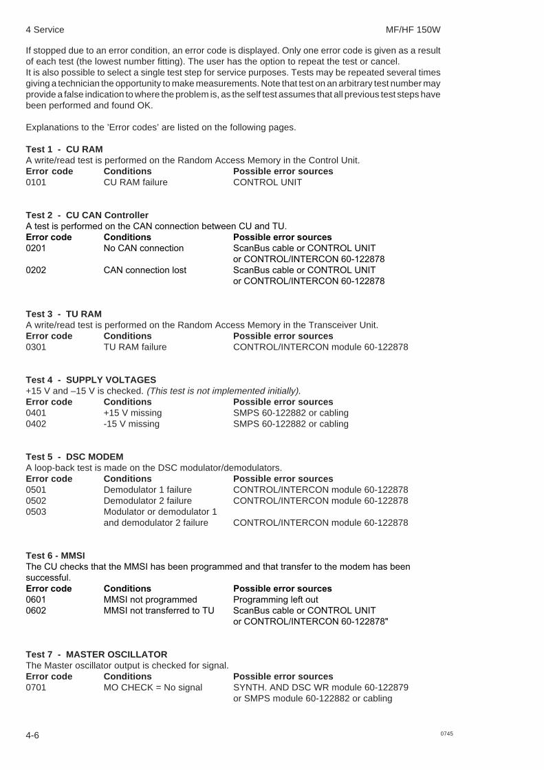
4 Service MF/HF 150W
4-6 0745
If stopped due to an error condition, an error code is displayed. Only one error code is given as a resultof each test (the lowest number fitting). The user has the option to repeat the test or cancel.It is also possible to select a single test step for service purposes. Tests may be repeated several timesgiving a technician the opportunity to make measurements. Note that test on an arbitrary test number mayprovide a false indication to where the problem is, as the self test assumes that all previous test steps havebeen performed and found OK.
Explanations to the ’Error codes’ are listed on the following pages.
Test 1 - CU RAMA write/read test is performed on the Random Access Memory in the Control Unit.Error code Conditions Possible error sources0101 CU RAM failure CONTROL UNIT
Test 2 - CU CAN ControllerA test is performed on the CAN connection between CU and TU.Error code Conditions Possible error sources0201 No CAN connection ScanBus cable or CONTROL UNIT
or CONTROL/INTERCON 60-1228780202 CAN connection lost ScanBus cable or CONTROL UNIT
or CONTROL/INTERCON 60-122878
Test 3 - TU RAMA write/read test is performed on the Random Access Memory in the Transceiver Unit.Error code Conditions Possible error sources0301 TU RAM failure CONTROL/INTERCON module 60-122878
Test 4 - SUPPLY VOLTAGES+15 V and –15 V is checked. (This test is not implemented initially).Error code Conditions Possible error sources0401 +15 V missing SMPS 60-122882 or cabling0402 -15 V missing SMPS 60-122882 or cabling
Test 5 - DSC MODEMA loop-back test is made on the DSC modulator/demodulators.Error code Conditions Possible error sources0501 Demodulator 1 failure CONTROL/INTERCON module 60-1228780502 Demodulator 2 failure CONTROL/INTERCON module 60-1228780503 Modulator or demodulator 1
and demodulator 2 failure CONTROL/INTERCON module 60-122878
Test 6 - MMSIThe CU checks that the MMSI has been programmed and that transfer to the modem has beensuccessful.Error code Conditions Possible error sources0601 MMSI not programmed Programming left out0602 MMSI not transferred to TU ScanBus cable or CONTROL UNIT
or CONTROL/INTERCON 60-122878"
Test 7 - MASTER OSCILLATORThe Master oscillator output is checked for signal.Error code Conditions Possible error sources0701 MO CHECK = No signal SYNTH. AND DSC WR module 60-122879
or SMPS module 60-122882 or cabling

4 Service MF/HF 150W
4-70745
Test 8 - 2. LO2. LO is checked for signal.Error code Conditions Possible error sources0801 2. LO CHECK = No signal SYNTH. AND DSC WR module 60-122879
Test 9 - 1. LO out of lockTests if 1. LO gets out of lock by setting it to an out-of-band frequency to check that the microprocessorcan control the synthesizer.
Settings:Band: 45 – 52.5 MHz1. LO: 75.00000 MHz
Error code Conditions Possible error sources0901 1. LO CHECK = Lock SYNTH. AND DSC WR module 60-122879
Test 10 - 1. LO band 0 low border1. LO is checked for lock in band 0, low border.Settings:Band: 45 – 52.5 MHz1. LO: 45.00000 MHzError code Conditions Possible error sources1001 1. LO CHECK = No lock SYNTH. AND DSC WR module 60-122879
Test 11 - 1. LO band 0 high border1. LO is checked for lock in band 0, high border.Settings:Band: 45 – 52.5 MHz1. LO: 52.50000 MHzError code Conditions Possible error sources1101 1. LO CHECK = No lock SYNTH. AND DSC WR module 60-122879
Test 12 - 1. LO band 1 low border1. LO is checked for lock in band 1, low border.Settings:Band: 52.5 - 60 MHz1. LO: 52.50000 MHzError code Conditions Possible error sources1201 1. LO CHECK = No lock SYNTH. AND DSC WR module 60-122879
Test 13 - 1. LO band 1 high border1. LO is checked for lock in band 1, high border.Settings:Band: 52.5 - 60 MHz1. LO: 60.00000 MHzError code Conditions Possible error sources1301 1. LO CHECK = No lock SYNTH. AND DSC WR module 60-122879
Test 14 - 1. LO band 2 low border1. LO is checked for lock in band 2, low border.Settings:Band: 60 – 67.5 MHz1. LO: 60.00000 MHzError code Conditions Possible error sources1401 1. LO CHECK = No lock SYNTH. AND DSC WR module 60-122879
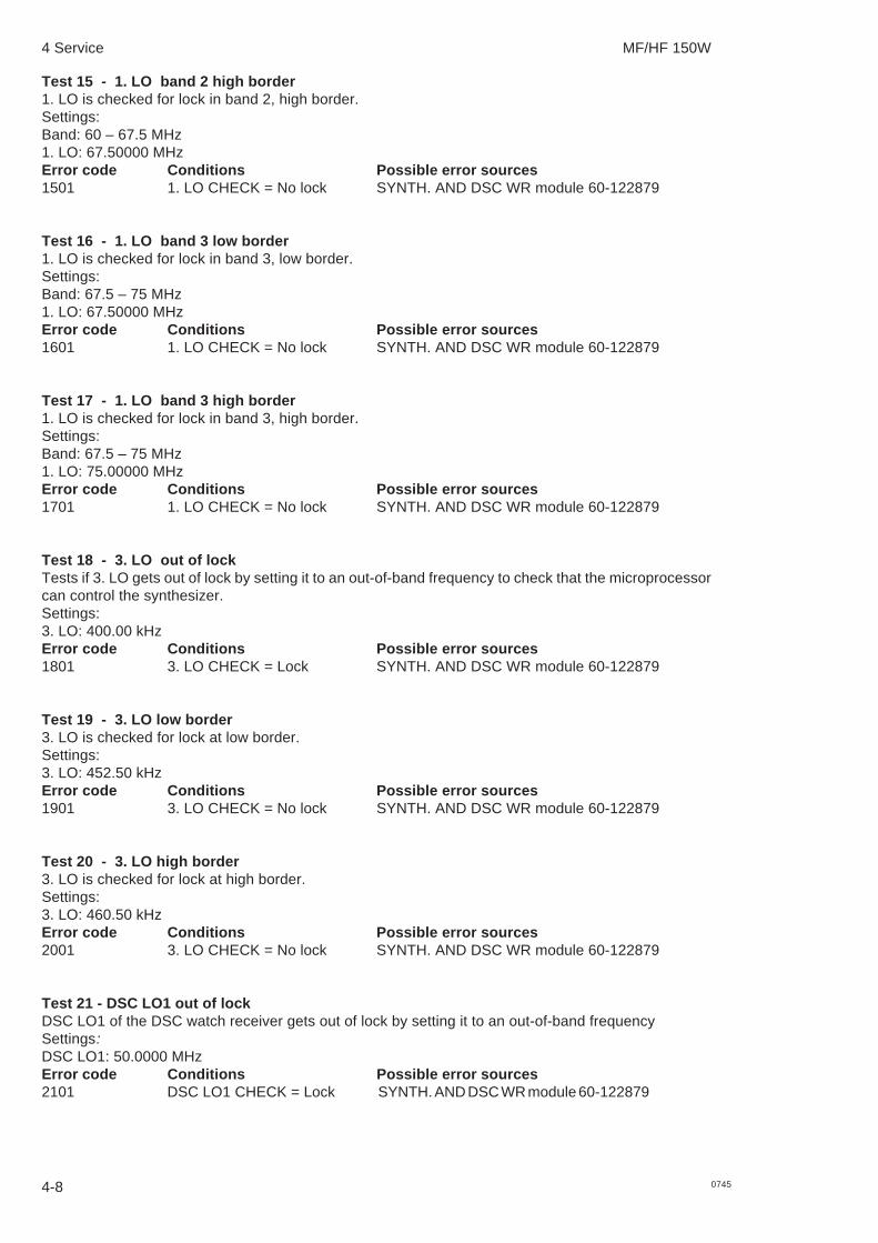
4 Service MF/HF 150W
4-8 0745
Test 15 - 1. LO band 2 high border1. LO is checked for lock in band 2, high border.Settings:Band: 60 – 67.5 MHz1. LO: 67.50000 MHzError code Conditions Possible error sources1501 1. LO CHECK = No lock SYNTH. AND DSC WR module 60-122879
Test 16 - 1. LO band 3 low border1. LO is checked for lock in band 3, low border.Settings:Band: 67.5 – 75 MHz1. LO: 67.50000 MHzError code Conditions Possible error sources1601 1. LO CHECK = No lock SYNTH. AND DSC WR module 60-122879
Test 17 - 1. LO band 3 high border1. LO is checked for lock in band 3, high border.Settings:Band: 67.5 – 75 MHz1. LO: 75.00000 MHzError code Conditions Possible error sources1701 1. LO CHECK = No lock SYNTH. AND DSC WR module 60-122879
Test 18 - 3. LO out of lockTests if 3. LO gets out of lock by setting it to an out-of-band frequency to check that the microprocessorcan control the synthesizer.Settings:3. LO: 400.00 kHzError code Conditions Possible error sources1801 3. LO CHECK = Lock SYNTH. AND DSC WR module 60-122879
Test 19 - 3. LO low border3. LO is checked for lock at low border.Settings:3. LO: 452.50 kHzError code Conditions Possible error sources1901 3. LO CHECK = No lock SYNTH. AND DSC WR module 60-122879
Test 20 - 3. LO high border3. LO is checked for lock at high border.Settings:3. LO: 460.50 kHzError code Conditions Possible error sources2001 3. LO CHECK = No lock SYNTH. AND DSC WR module 60-122879
Test 21 - DSC LO1 out of lockDSC LO1 of the DSC watch receiver gets out of lock by setting it to an out-of-band frequencySettings:DSC LO1: 50.0000 MHzError code Conditions Possible error sources 2101 DSC LO1 CHECK = Lock SYNTH. AND DSC WR module 60-122879

4 Service MF/HF 150W
4-90745
Test 22 - DSC LO1 Low VCO lockedDSC LO1 lower band VCO of the DSC Watch Receiver is checked for phase-lock.Settings:DSC LO1: 33.0000 MHzError code Conditions Possible error sources 2201 DSC 1. LO CHECK = No lock SYNTH. AND DSC WR module 60-122879
Test 23 - DSC LO1 medium VCO lockedDSC LO1 medium band VCO of the DSC Watch Receiver is checked for phase-lock.Settings:DSC LO1: 37.0000 MHzError code Conditions Possible error sources 2201 DSC 1. LO CHECK = No lock SYNTH. AND DSC WR module 60-122879 Test 24 - DSC LO1 high VCO lockedDSC LO1 upper band VCO of the DSC Watch Receiver is checked for phase-lock.Settings:DSC LO1: 33.0000 MHzError code Conditions Possible error sources 2201 DSC 1. LO CHECK = No lock SYNTH. AND DSC WR module 60-122879
[Test 25 - reserved]
[Test 26 - reserved]
[Test 27 - reserved]
[Test 28 - reserved]
[Test 29 - reserved]
[Test 30 - reserved]
Test 31 - RX SSB modeThe receiver of the RX/EX Signal Path 60-122880 is checked in SSB mode. By choosing the propersynthesizer frequencies the signal passes the 45 MHz filter and is mixed to a 1 kHz tone in the audio part.The automatic gain control voltage and RX AF is checked.Settings:Band: 45 – 52.5 MHz1. LO: 44.99900 MHz3. LO: 456.00 kHzError code Conditions Possible error sources3101 RX AF CHECK 515 = No signal RX/EX SIGNAL PATH module 60-1228803102 RX AF CHECK 510 = No signal CONTROL/INTERCON module 60-1228783103 No AGC voltage RX/EX SIGNAL PATH module 60-122880 or
CONTROL/INTERCON module 60-122878 orcabling
Test 32 - RX AM modeThe receiver of the RX/EX Signal Path 60-122880 is checked in AM mode. By choosing the propersynthesizer frequency the signal passes the 45 MHz filter and is mixed to generate an unmodulatedcarrier. The automatic gain control voltage and RX AF is checked.Settings:Band: 45 – 52.5 MHz1. LO: 44.99900 MHzError code Conditions Possible error sources3201 RX AF CHECK 515 = Signal RX/EX SIGNAL PATH module 60-1228803202 No AGC voltage RX/EX SIGNAL PATH module 60-122880 or
CONTROL/INTERCON module 60-122878

4 Service MF/HF 150W
4-10 0745
Test 33 - RX DSC modeThe receiver of the RX/EX Signal Path 60-122880 is checked in DSC mode. By choosing the propersynthesizer frequencies the signal passes the 45 MHz filter and is mixed to a 1.7 kHz tone in the audiopart. RX AF is checked.Settings:Band: 45 – 52.5 MHz1. LO: 44.99900 MHz3. LO: 456.70 kHzError code Conditions Possible error sources3301 DSC AF CHECK = No signal RX/EX SIGNAL PATH module 60-1228803302 RX AF CHECK 515 = No signal RX/EX SIGNAL PATH module 60-1228803303 RX AF CHECK 510 = No signal CONTROL/INTERCON module 60-122878
Test 34 - SQUELCHThe squelch circuit of the RX/EX Signal Path 60-122880 is checked in SSB mode. By choosing the propersynthesizer frequencies the signal passes the 45 MHz filter and is mixed to a 500 Hz tone in the audiopart. This makes the squelch open. Then a 2 kHz tone is generated making the squelch close. Squelchhold time is also checked.Settings:Band: 45 – 52.5 MHz1. LO: 44.99900 MHza) 3. LO: 455.50 kHz (500Hz tone)b) 3. LO: 457.00 kHz (2 kHz tone)Error code Conditions Possible error sources3401 RX AF CHECK 515 = No signal RX/EX SIGNAL PATH module 60-122880
with 500 Hz tone.3402 RX AF CHECK 515 = Signal RX/EX SIGNAL PATH module 60-122880
with 2 kHz tone.3403 Squelch hold time not ok. RX/EX SIGNAL PATH module 60-122880
Test 35 - RX AGCThe gain control circuit of the RX/EX Signal Path 60-122880 is checked . By choosing the propersynthesizer frequency the signal passes the 45 MHz filter and is mixed to a 1 kHz tone in the audio part.By setting the MGC voltage to low sensitivity the RX AF Check should indicate no AF signal. By settingthe MGC voltage to high sensitivity the RX AF Check should indicate AF signal present.Settings:Band: 45 – 52.5 MHz1. LO: 44.99900 MHz3. LO: 456.00 kHzError code Conditions Possible error sources3501 RX AF CHECK 515 = Signal RX/EX SIGNAL PATH module 60-122880 or
with MGC voltage at max. CONTROL/INTERCON module 60-1228783502 RX AF CHECK 515 = No signal RX/EX SIGNAL PATH module 60-122880 or
with MGC voltage at min. CONTROL/INTERCON module 60-122878
Test 36 - RX ACG hang timeThe Automatic Gain Control Hang facility of the RX/EX Signal Path 60-122880 is checked. By choosingthe proper synthesizer frequency the signal passes the 45 MHz filter and is mixed to a 1 kHz tone in theaudio part. The hang function is examined in three steps:1) Check normal AGC with 1 kHz tone2) Check that AGC hangs with no signal3) Check that AGC hang time has ended.Settings:Band: 45 – 52.5 MHz1. LO: 44.99900 MHz3. LO: 456.00 kHzBand: 67.5 – 75 MHz1. LO: 80.00000 MHz3. LO: 456.00 kHz
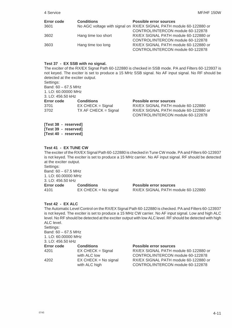
4 Service MF/HF 150W
4-110745
Error code Conditions Possible error sources3601 No AGC voltage with signal on RX/EX SIGNAL PATH module 60-122880 or
CONTROL/INTERCON module 60-1228783602 Hang time too short RX/EX SIGNAL PATH module 60-122880 or
CONTROL/INTERCON module 60-1228783603 Hang time too long RX/EX SIGNAL PATH module 60-122880 or
CONTROL/INTERCON module 60-122878
Test 37 - EX SSB with no signal.The exciter of the RX/EX Signal Path 60-122880 is checked in SSB mode. PA and Filters 60-123937 isnot keyed. The exciter is set to produce a 15 MHz SSB signal. No AF input signal. No RF should bedetected at the exciter output.Settings:Band: 60 – 67.5 MHz1. LO: 60.00000 MHz3. LO: 456.50 kHzError code Conditions Possible error sources3701 EX CHECK = Signal RX/EX SIGNAL PATH module 60-1228803702 TX AF CHECK = Signal RX/EX SIGNAL PATH module 60-122880 or
CONTROL/INTERCON module 60-122878
[Test 38 - reserved][Test 39 - reserved][Test 40 - reserved]
Test 41 - EX TUNE CWThe exciter of the RX/EX Signal Path 60-122880 is checked in Tune CW mode. PA and Filters 60-123937is not keyed. The exciter is set to produce a 15 MHz carrier. No AF input signal. RF should be detectedat the exciter output.Settings:Band: 60 – 67.5 MHz1. LO: 60.00000 MHz3. LO: 456.50 kHzError code Conditions Possible error sources4101 EX CHECK = No signal RX/EX SIGNAL PATH module 60-122880
Test 42 - EX ALCThe Automatic Level Control on the RX/EX Signal Path 60-122880 is checked. PA and Filters 60-123937is not keyed. The exciter is set to produce a 15 MHz CW carrier. No AF input signal. Low and high ALClevel. No RF should be detected at the exciter output with low ALC level. RF should be detected with highALC level.Settings:Band: 60 – 67.5 MHz1. LO: 60.00000 MHz3. LO: 456.50 kHzError code Conditions Possible error sources4201 EX CHECK = Signal RX/EX SIGNAL PATH module 60-122880 or
with ALC low CONTROL/INTERCON module 60-1228784202 EX CHECK = No signal RX/EX SIGNAL PATH module 60-122880 or
with ALC high CONTROL/INTERCON module 60-122878

4 Service MF/HF 150W
4-12 0745
Test 43 - ATU without RF powerThe ATU Module 60-122883 is checked without transmitting. The Transceiver Unit checks that an ATUis connected and is able to communicate with the TU. The ATU tests RAM, Vforward-, Vreflected-, 0degrees-, 90 degrees-, and temperature- detectors.Error code Conditions Possible error sources4301 ‘ATU not installed’ selected Select CONTINUE to bypass test
in FUNC menu.4302 Communication failure ATU or CONTROL/INTERCON module 60-122878
or coax cable4303 ATU RAM error ATU4304 Vforward detector ATU4305 Vreflected detector ATU4306 0 degrees detector ATU4307 90 degrees detector ATU4308 Temperature sensor ATU
[Test 44 - reserved][Test 45 - reserved]
Test 46 - TXThe user may enter a test frequency and listen for signals to ensure that the frequency is free, before thetransmitter tests are carried out.PA and Filters 60-123937 and ATU Module 60-122883 is checked. A full tune and ALC procedure isperformed on a frequency chosen by the user. Then a transmission with full power is carried out for 10seconds, followed by a transmission in low power mode also lasting 10 seconds.Error code Conditions Possible error sources4610 Tune power low W1 or W2 or W8 or W114611 Tune power high W1 or W24612 ALC power high W1 or W24613 Supply failure W14614 ALC power low W1 or W24615 TU – ATU failure Coax cable TU – ATU or Antenna installation or W15
or ATU4616 Low power high W1 or W24617 Full power high W1 or W24620 PA temperature high PA AND FILTERS module4621 PA SWR high Antenna installation or
PA AND FILTERS module4640 Not tuned Antenna installation or ATU4641 No tune power CONTROL/INTERCON module 60-122878 or W15or
Coax cable TU – ATU shorted or ATU4642 Bad SWR Antenna installation or ATU4646 Bad SWR TX Antenna installation or ATU
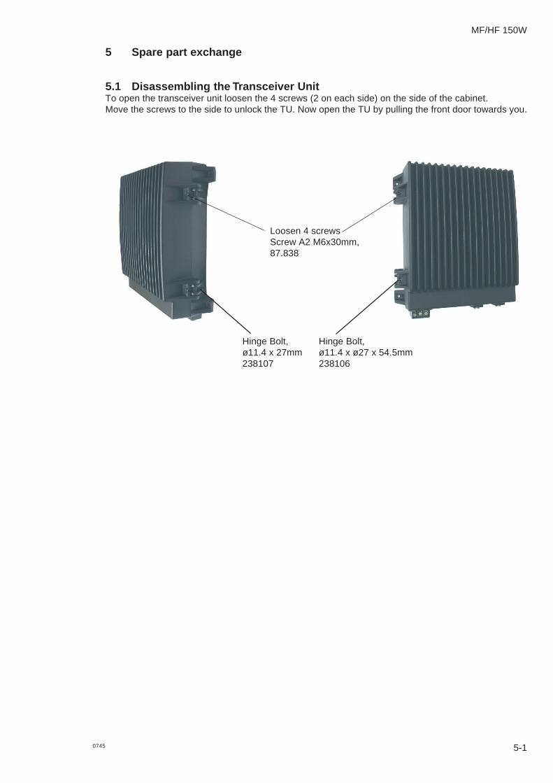
5 Spare part exchange
5.1 Disassembling the Transceiver UnitTo open the transceiver unit loosen the 4 screws (2 on each side) on the side of the cabinet.Move the screws to the side to unlock the TU. Now open the TU by pulling the front door towards you.
5-1
MF/HF 150W
0745
Loosen 4 screwsScrew A2 M6x30mm,87.838
Hinge Bolt,ø11.4 x 27mm238107
Hinge Bolt,ø11.4 x ø27 x 54.5mm238106

5 Spare part exchange MF/HF 150W
5-2 0745
5.2 Transceiver Unit module locationThe following modules are available as service parts.
C169
R51
R35
C44
C209
R26
R176
C35
C36
N3
R49
R46
C157
C194
C37
C38
H25
R50
V18
C195
C154
R162
C142
C158
H27
V50
V13
R36
H29
R136
R163
R130
H28
R132
C228
R131
R129
C153
R128
C205
R127
C198
C152
H6
C229
R137
H26
R38
V19
H21
H7
C189
R19
R173
H32
H24
R94
T1
E2
H33
C244
C182
H14
C19
V70
V47
C193
C150
R83
C100
R179
E1
H8
R169
R82
T2
C236
H30
C151
X16
H1
R149
V20
R85
H35
V21
H19
V6
R100
H4
C241
C177
R56
R2
R148
D4
N6
R71
H22
R37
C226
C23
C29
C191
C179
C197
C178
E3
H9
R89
R75
H37
C99
C192
C159
C160
C22
C30
C27
C190
C188
C196
V12
C161
C162
R161
H5
C165
V7
C203
V34
H20
V55
R98
R96
H12
C167
C166
R90
C2
C1
C69
H23
R84
C238
H17
X5
X3
H10
X4
H2
H13
H11
H16
X2
H18
H15
H31
D3
X100
C253
R154
C24
C25
C39
C9
C156
C174
C199
C200
C240
X17
V45
R70
N2
R158
R157
N4
R24
R25
V43
D1
C246
C168
C155
C181
R174
L21
C227
C11
C235
C208
V17
R55
C170
C171
L22
C28
R18
C101
C206
C57
C67
C237
C239
C52
C53
R159
H41
H42
H43
H44
H48 H49
C54
C176
C175
C183
T3
R178
R95
R155
C107
C121
R80
C13
C15
C14
C249
R7
C8
L1
R164
C10
V46
V30
C123
R5
R6
R12
V10 V9 V8V11V59V60
R102
R21
R20
C7
C6
R22
R181
R23
C124
R182
R10
R17
R15
C137
R9C4
R11
C18
V33
R92
R166
C59
V37
V53
V42
R91
R139
R140
C113
V44
R69
C255
R202
R203
H47
V71
C95
C254
R134
R175
R3
R4
R14
R86
N1
X11
V4
V5
R146
C212
R145
R144
R143
R77
R79
R81
R147
R1
R151
R152
R153
R31
R66
C114
R185
R53
C102
C103
R52
R165
C242
C173
C180
C172
C48
C73
C108
R106
R105
R104
R103
R97
K10
L31
X7
L40
R123
R124
R126
C134
R112
C75
C221
K8
L12
K3
C85
R42
R43
C147
L42R125
R122
L41
R116
L56
L51
R114
R113
R115
C70
C71
C93
L57
C252
V26
R28
R30
R63
R138
L44
L45
V3
C245
R171
R172
C233
C72
C97
C96
C63
X8
R135
R142
R133
R167
R168
L50
C84
K16
K15
L55
K9
C16
R160
C17
R101
C40
V25
V24
V23
V22
C41
C42
C43
K11
C184
L8
V15
V40
N9
N10
R200
N12
R206
R208
R156
N5
R99
N8
R198
R204
N11
N13
R61
R170
R207
R205
R201
R199
C213
N16
R189
C243
C185
V35
H45
H46
R111
R110
R109
R108
R107
V36
N14V14
V28
R41
R45
R59
V16
R183
C216C217
R184
R88
N19
N20
N27
R74
R33
N17
R39
N18
R48
N21R68
N22R73
R72
R67
R47
R44
R40
R34
R32
V27
N23R58
R57
C14
6
C122
R195
R210
R211
C49
C222
C223
C34
C224
N24C234
C232
C32
R65
C218R190
C201
C202
R14
1
V31
R212
C225
N25
C231
R191
L53
R177
C64
C132
C130
C129
C131
R186
R187
R188
R197
R93
R192
R213
R209
C230
L30
V52
V51
L43
V48
C80
C98
L32
L11
K12
L13
K14
C145
C143
C126
R13
R27
C215
C105
C104
C214
C210
C148
C149
C20C21
C256
C45
R64
R196
C125
C110
C112
L14
L9
C111
V2
C109
C140
V32
R217
R218
R219
R216
R220
R214
R215
R194
C120
R54
L16
C115
C118
C46
C12
C207
V49 R29
R16
L54
C119
R193
R62 C117
L15
C33
C47
R60
C128
C133
C136
C219
C220
C61
C62
N7
C68
C247
C78
C211
C106
C139
R180
C3
R150
L52
C79
C65
C127
C94
C186
C187
C66
C204
C77
C81
C76
C92
C89
C88
C86
C144
C135
C141
C87
C90
C50
C31
K13
C138
N15
C163
C164
C26
C250
C248
L46
C251
C5R8
X8
X5
R63
X1
X2
R180
R178
X3
X4
X11
+-
99-126496
1 1
W3
11
11
W4
W5
11
W1
W2
111
1
TX
W10
DSC RX
W8
W14
W13
W11
W12
W9
3.LO
2. LO
EX
1.LO
RX
SCANBUS
SYS
SUPPLY
DSC RX
RX/TX
24 V DC
ALARM
W15
W7
W6
CONTROL/INTERCON. 60-122878DSC WR 60-122879
SYNTHESIZER AND
PATH 60-122880
RX/EX SIGNAL
SMPS 60-122882
W16
RX TELEX
M0. ADJ
PA AND FILTERS 60-123937

5 Spare part exchange MF/HF 150W
Control / Intercon. module 60-122878
Synthesizer and DSC WR module 60-122879
RX/EX Signal path module 60-122880
PA and filters module 60-123937
SMPS module 60-122882
5-30745

5 Spare part exchange MF/HF 150W
5-4 0745
5.3 Required service toolFor disassembling transceiver unit Slotted screwdriverFor shield cover, print and cables Torx screwdriver
5.4 Accessory list
NAME PART NO.5083 29A Power Supply 405083AAC Power Supply 804655xx(*)AC Power Supply Class E 8046650006Battery Charger 804656xx(*)Battery Charger Class E 80466600065070 External 8W speaker 405070CB4616 SUBD-9 to Terminal Block Converter 804616 (*)CB4618 Handset Connection Box 804618 (*)3-wire Data download Cable 532506ATU Mounting Kit:Mounting plate and fittings for mast. 737589Mounting plate 737588Gasket kit for Antenna Tuning Unit 737822
* (Please find specific order numbers in User Manual)