Embed Size (px)
Citation preview

Seawater Desalination Module
SALINO Pressure Center
Installation/Operating Manual
engineered by

Legal information/Copyright
Installation/Operating Manual SALINO Pressure Center
Original operating manual
All rights reserved. The contents provided herein must neither be distributed, copied, reproduced, edited orprocessed for any other purpose, nor otherwise transmitted, published or made available to a third party withoutthe manufacturer's express written consent.
Subject to technical modification without prior notice.
© Salinnova GmbH, Bobenheim-Roxheim 11.11.2017
Contents
Glossary ......................................................................................................................................... 5
1 General .......................................................................................................................................... 6
1.1 Principles .......................................................................................................................................................6
1.2 Target group ..................................................................................................................................................6
1.3 Other applicable documents ..........................................................................................................................6
1.4 Symbols .........................................................................................................................................................6
2 Safety ............................................................................................................................................. 7
2.1 Key to safety symbols/markings ....................................................................................................................7
2.2 General ..........................................................................................................................................................7
2.3 Intended use ..................................................................................................................................................7
2.4 Personnel qualification and training ..........................................................................................................… 8
2.5 Consequences and risks caused by non-compliance with this manual .....................................................8
2.6 Safety awareness ..........................................................................................................................................8
2.7 Safety information for the operator/user ..................................................................................................… 9
2.8 Safety information for maintenance, inspection and installation ...........................................................….. 9
2.9 Unauthorised modes of operation .................................................................................................…............9
3 Transport/Temporary Storage/Disposal ..................................................................................…. 10
3.1 Checking the condition upon delivery .....................................................................................................…10
3.2 Transport ....................................................................................................................................................10
3.3 Storage/preservation ..................................................................................................................................10
3.4 Return to supplier .......................................................................................................................................11
3.5 Disposal .....................................................................................................................................................11
4 Description of the Pump (Set) .................................................................................................... 13
4.1 General description ....................................................................................................................................13
4.2 Designation ................................................................................................................................................13
4.3 Name plate .............................................................................................................................................…13
4.4 Design details ............................................................................................................................................13
4.5 Configuration and function .........................................................................................................................14
4.6 Noise characteristics ..................................................................................................................................16
4.7 Scope of supply ..........................................................................................................................................16
4.8 Dimensions and weights .............................................................................................................................16
4.9 Filtration ......................................................................................................................................................16
5 Installation at Site ....................................................................................................................... 17
5.1 Safety regulations .......................................................................................................................................17
5.2 Checks to be carried out prior to installation ..........................................................................................… 17
5.3 Installing the pump set ................................................................................................................................18
5.4 Pipes/hoses ................................................................................................................................................19
5.5 Protective equipment ..................................................................................................................................21
Contents
SALINO Pressure Center 3 of 54

5.6 Checking the coupling alignment ...............................................................................................................23
5.7 Electrical system ........................................................................................................................................24
5.8 Checking the direction of rotation ..............................................................................................................25
6 Commissioning/Start-up/Shutdown ........................................................................................... 27
6.1 Commissioning/start-up .........................................................................................................................… 27
6.2 Operating limits ..........................................................................................................................................31
6.3 Shutdown/storage/preservation .................................................................................................................34
6.4 Returning to service ...................................................................................................................................35
7 Servicing/Maintenance ............................................................................................................... 36
7.1 Safety regulations ......................................................................................................................................36
7.2 Servicing/inspection ...................................................................................................................................37
7.3 Drainage/cleaning ......................................................................................................................................39
7.4 Dismantling the pump set ..........................................................................................................................39
7.5 Reassembling the pump set ......................................................................................................................42
7.6 Tightening torques .....................................................................................................................................44
7.7 Spare parts stock .......................................................................................................................................44
8 Trouble-shooting ........................................................................................................................ 45
9 Related Documents .................................................................................................................... 47
9.1 Exploded view and list of components .......................................................................................................47
9.2 Dimensions and connections .....................................................................................................................48
10 EC Declaration of Conformity .................................................................................................… 50
11 Certificate of Decontamination ..............................................................................................… 51
Index ....................................................................................................................................…. 52
Contents
4 of 54 SALINO Pressure Center
Glossary
Back pressure
The pressure at the "Low Pressure Out"connection of the energy recovery device.
Certificate of decontamination
A certificate of decontamination is enclosed bythe customer when returning the product tothe manufacturer to certify that the producthas been properly drained to eliminate anyenvironmental and health hazards arising fromcomponents in contact with the fluid handled.
Discharge line
The line connected to the pump's "HighPressure Out" connection and the energyrecovery device's "High Pressure In"connection.
Drains
Connections on the pump and energy recoverydevice used to drain the lubricant via drainlines.
Drive end
The side of the pump which faces the motor
Inlet line
The line connected to the pump's "LowPressure In" connection.
Inlet pressure
The pressure at the "Low Pressure In"connection of the pump.
Outlet line
The line connected to the energy recoverydevice's "Low Pressure Out" connection andthe lines used to discharge the lubricant ofboth the pump and energy recovery device.
Pump
Machine without drive, additional componentsor accessories
Pump end
The side of the pump which faces away fromthe motor
Pump set
Complete pump set consisting of pump, drive,additional components and accessories
Glossary
SALINO Pressure Center 5 of 54
1 General
1.1 PrinciplesThis operating manual is supplied as an integral part of the type series and variants
indicated on the front cover. The manual describes the proper and safe use of thisequipment in all phases of operation.
The name plate indicates the type series and size, the main operating data, the ordernumber and the order item number. The order number and order item numberuniquely identify the pump (set) and serve as identification for all further businessprocesses.
In the event of damage, immediately contact your nearest KSB service centre tomaintain the right to claim under warranty.
Noise characteristics see (⇨ Section 4.6 Page 16)
1.2 Target group
This operating manual is aimed at the target group of trained and qualified specialisttechnical personnel. ( ⇨ Section 2.4 Page 8)
1.3 Other applicable documents
Table 1: Overview of other applicable documents
Document ContentsData sheet Description of the technical data of the pump (set)Sub-supplier product literature Operating manuals and other product literature
describing accessories and integrated machinerycomponents
Spare parts lists Description of spare parts
For accessories and/or integrated machinery components, observe the relevantmanufacturer's product literature.
1.4 Symbols
Table 2: Symbols used in this manual
Symbol Description
✓ Conditions which need to be fulfilled before proceeding with thestep-by-step instructions
⊳ Safety instructions⇨ Result of an action⇨ Cross-references1.
2.
Step-by-step instructions
NoteRecommendations and important information on how to handlethe product
1 General
6 of 54 SALINO Pressure Center

2 SafetyAll the information contained in this section refers to hazardous situations.
2.1 Key to safety symbols/markings
Table 3: Definition of safety symbols/markings
Symbol Description
! DANGER DANGERThis signal word indicates a high-risk hazard which, if not avoided,will result in death or serious injury.
! WARNING WARNINGThis signal word indicates a medium-risk hazard which, if notavoided, could result in death or serious injury.
CAUTION CAUTIONThis signal word indicates a hazard which, if not avoided, couldresult in damage to the machine and its functions.General hazardIn conjunction with one of the signal words this symbol indicates ahazard which will or could result in death or serious injury.
Electrical hazardIn conjunction with one of the signal words this symbol indicates ahazard involving electrical voltage and identifies information aboutprotection against electrical voltage.Machine damage In conjunction with the signal word CAUTION this symbol indicatesa hazard for the machine and its functions.
2.2 General
This manual contains general installation, operating and maintenance instructionsthat must be observed to ensure safe pump operation and prevent personal injuryand damage to property.
The safety information in all sections of this manual must be complied with.
This manual must be read and completely understood by the specialist personnel/operators responsible prior to installation and commissioning.
The contents of this manual must be available to the specialist personnel at the siteat all times.
Information attached directly to the pump must always be complied with and bekept in a perfectly legible condition at all times. This applies to, for example:
▪ Arrow indicating the direction of rotation
▪ Markings for connections
▪ Name plate
The operator is responsible for ensuring compliance with all local regulations nottaken into account in this manual.
2.3 Intended use
▪ The product must only be operated within the operating limits described in theother applicable documents. ( ⇨ Section 1.3 Page 6)
▪ Only operate pumps/pump sets which are in perfect technical condition.
▪ Do not operate the pump (set) in partially assembled condition.
▪ Only use the pump (set) to handle the fluids described in the data sheet orproduct literature of the pump model.
▪ Never operate the pump (set) without the fluid to be handled.
▪ Observe the minimum speed indicated on the data sheet or in the productliterature (prevents overheating, bearing damage, etc.).
! DANGER
2 Safety
SALINO Pressure Center 7 of 54
▪ Observe the maximum speed indicated on the data sheet or in the productliterature (prevents overheating, mechanical seal damage, cavitation damage,bearing damage, etc.)
▪ Never operate the pump (set) at a pressure below the specified inlet pressure(prevention of cavitation damage).
▪ Never operate the pump (set) below the specified back pressure.
▪ Consult the manufacturer about any use or mode of operation not described inthe data sheet or product literature.
Prevention of foreseeable misuse
▪ The pressure at the pump inlet must never fall below the inlet pressure specified.
– Risk of cavitation damage
▪ The energy recovery device must not be operated below the specified backpressure (prevention of cavitation damage).
▪ Never exceed the permissible operating limits specified in the data sheet orproduct literature regarding pressure, temperature, etc.
▪ Never install throttling elements in the outlet pipes of the pump and energyrecovery device or in the lubricating flow's drain pipe.
▪ Observe all safety information and instructions in this manual.
Also see
● Other applicable documents [ ⇨ 6]
2.4 Personnel qualification and training
All personnel involved must be fully qualified to transport, install, operate, maintainand inspect the machinery this manual refers to.
The responsibilities, competence and supervision of all personnel involved intransport, installation, operation, maintenance and inspection must be clearlydefined by the operator.
Deficits in knowledge must be rectified by means of training and instructionprovided by sufficiently trained specialist personnel. If required, the operator cancommission the manufacturer/supplier to train the personnel.
Training on the pump (set) must always be supervised by technical specialistpersonnel.
2.5 Consequences and risks caused by non-compliance with this manual
▪ Non-compliance with this operating manual will lead to forfeiture of warrantycover and of any and all rights to claims for damages.
▪ Non-compliance can, for example, have the following consequences:
– Hazards to persons due to electrical, thermal, mechanical and chemicaleffects and explosions
– Failure of important product functions
– Failure of prescribed maintenance and servicing practices
– Hazard to the environment due to leakage of hazardous substances
2.6 Safety awareness
In addition to the safety information contained in this manual and the intended use,the following safety regulations shall be complied with:
▪ Accident prevention, health and safety regulations
▪ Explosion protection regulations
▪ Safety regulations for handling hazardous substances
▪ Applicable standards, directives and laws
2 Safety
8 of 54 SALINO Pressure Center

2.7 Safety information for the operator/user
▪ The operator shall fit contact guards for hot, cold and moving parts and checkthat the guards function properly.
▪ Do not remove any contact guards during operation.
▪ Provide the personnel with protective equipment and make sure it is used.
▪ Contain leakages (e.g. at the shaft seal) of hazardous fluids handled (e.g.explosive, toxic, hot) so as to avoid any danger to persons and the environment.Adhere to all relevant laws.
▪ Eliminate all electrical hazards. (In this respect refer to the applicable nationalsafety regulations and/or regulations issued by the local energy supplycompanies.)
▪ If shutting down the pump does not increase potential risk, fit an emergency-stop control device in the immediate vicinity of the pump (set) during pump setinstallation.
2.8 Safety information for maintenance, inspection and installation
▪ Modifications or alterations of the pump are only permitted with themanufacturer's prior consent.
▪ Use only original spare parts or parts authorised by the manufacturer. The use ofother parts can invalidate any liability of the manufacturer for resulting damage.
▪ The operator ensures that maintenance, inspection and installation is performedby authorised, qualified specialist personnel who are thoroughly familiar withthe manual.
▪ Only carry out work on the pump (set) during standstill of the pump.
▪ The pump casing must have cooled down to ambient temperature.
▪ Pump pressure must have been released and the pump must have been drained.
▪ When taking the pump set out of service always adhere to the proceduredescribed in the manual. ( ⇨ Section 6.3 Page 34)
▪ Decontaminate pumps which handle fluids posing a health hazard.
▪ As soon as the work has been completed, re-install and/or re-activate any safety-relevant and protective devices. Before returning the product to service, observeall instructions on commissioning. ( ⇨ Section 6.1 Page 27)
2.9 Unauthorised modes of operation
Never operate the pump (set) outside the limits stated in the data sheet and in thismanual.
The warranty relating to the operating reliability and safety of the supplied pump(set) is only valid if the equipment is used in accordance with its intended use.
2 Safety
SALINO Pressure Center 9 of 54
3 Transport/Temporary Storage/Disposal
3.1 Checking the condition upon delivery
1. On transfer of goods, check each packaging unit for damage.
2. In the event of in-transit damage, assess the exact damage, document it andnotify Salinnova or the supplying dealer (as applicable) and the insurer about thedamage in writing immediately.
3.2 Transport
DANGER
Improper transportDanger to life from falling parts!
▷ Observe the safety regulations for transport work. ( ⇨ Section 2 Page 7)(⇨ Section 3 Page 10)
▷ Observe the applicable local occupational safety and accident preventionregulations.
DANGER
The pump (set) could slip out of the suspension arrangementDanger to life from falling parts!
▷ Always transport the pump (set) in the specified position.
▷ Never suspend the pump from its free shaft end.
▷ Pay attention to the weight data and the centre of gravity.
▷ Observe the applicable local health and safety regulations.
▷ Use suitable, permitted lifting accessories, e.g. self-tightening lifting tongs.
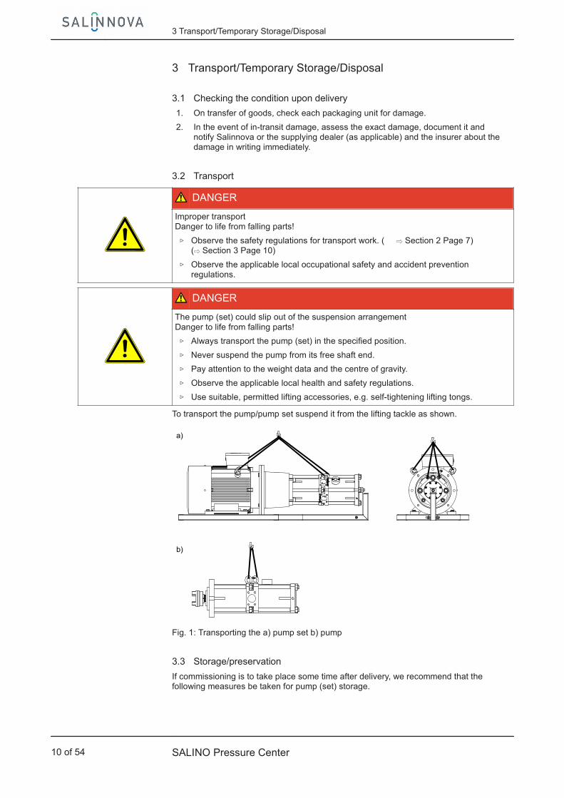
To transport the pump/pump set suspend it from the lifting tackle as shown.
a)
b)
Fig. 1: Transporting the a) pump set b) pump
3.3 Storage/preservation
If commissioning is to take place some time after delivery, we recommend that thefollowing measures be taken for pump (set) storage.
3 Transport/Temporary Storage/Disposal
10 of 54 SALINO Pressure Center

CAUTIONDamage during storage by humidity, dirt, or verminCorrosion/contamination of the pump (set)!
▷ For outdoor storage cover the packed or unpacked pump (set) and accessorieswith waterproof material.
CAUTIONWet, contaminated or damaged openings and connectionsLeakage or damage to the pump!
▷ Clean and cover pump openings and connections as required prior to puttingthe pump into storage.
Store the pump (set) in a dry, protected room where the atmospheric humidity is asconstant as possible.
If properly stored indoors, the pump set is protected for a maximum of 12 months.New pumps/pump sets are supplied by our factory duly prepared for storage.
For storing a pump (set) which has already been operated, observe the instructions in(⇨ Section 6.3 Page 34) .
3.4 Return to supplier
1. Drain the pump as per operating instructions. ( ⇨ Section 7.3 Page 39)
2. Always flush and clean the pump, particularly if it has been used for handlingnoxious, explosive, hot or other hazardous fluids.
3. If the pump set has handled fluids whose residues could lead to corrosion in thepresence of atmospheric humidity or could ignite upon contact with oxygen,the pump set must also be neutralised, and anhydrous inert gas must be blownthrough the pump to ensure drying.
4. Always complete and enclose a certificate of decontamination when returningthe pump (set).Always indicate any safety and decontamination measures taken. ( ⇨ Section 11Page 51)
NOTEIf required, a blank certificate of decontamination can be downloaded from theweb site at: www.salinnova.com/certificate_of_decontamination
3.5 Disposal
WARNING
Fluids, consumables and supplies which are hot and/or pose a health hazardHazard to persons and the environment!
▷ Collect and properly dispose of flushing fluid and any residues of the fluidhandled.
▷ Wear safety clothing and a protective mask, if required.
▷ Observe all legal regulations on the disposal of fluids posing a health hazard.
1. Dismantle the pump (set).Collect greases and other lubricants during dismantling.
2. Separate and sort the pump materials, e.g. by:- Metals- Plastics- Electronic waste- Greases and other lubricants
3 Transport/Temporary Storage/Disposal
SALINO Pressure Center 11 of 54

3. Dispose of materials in accordance with local regulations or in anothercontrolled manner.
3 Transport/Temporary Storage/Disposal
12 of 54 SALINO Pressure Center
4 Description of the Pump (Set)
4.1 General description
▪ Seawater desalination module
For drinking water production and treatment by reverse osmosis in industry, hotels,resorts and ships.
4.2 Designation
Example: SALINO PC-23-40-D
Table 4: Key to the designation
Code DescriptionSALINO Type seriesPC Design
PC Pressure Center23 Flow rate [m ³/h] (size)
14, 20, 23, 6540 Drinking water yield / Recovery Rate [%]D Material
D Duplex stainless steel
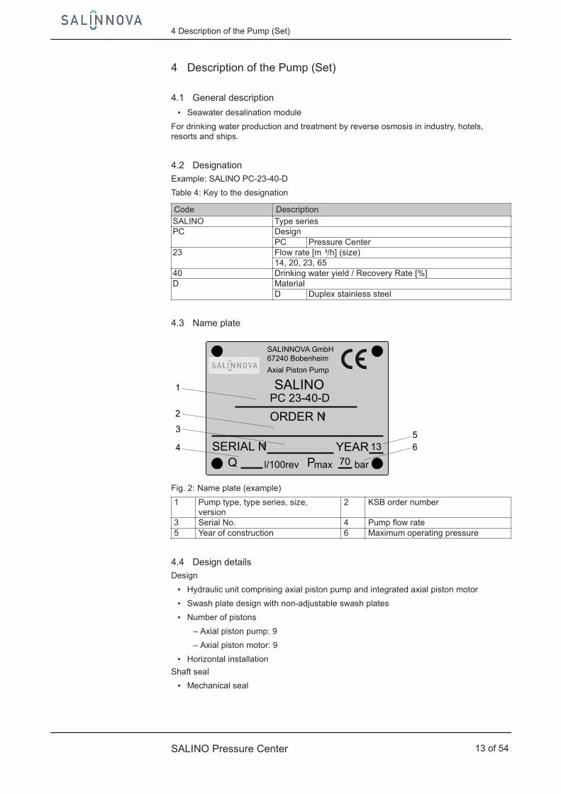
4.3 Name plate
SALINNOVA GmbH67240 Bobenheim
SALINOAxial Piston Pump
PC 23-40-D
ORDER No
SERIAL No YEAR 13
Q l/100rev Pmax 70 bar
4
53
2
1
6
Fig. 2: Name plate (example)
1 Pump type, type series, size,version
2 KSB order number
3 Serial No. 4 Pump flow rate5 Year of construction 6 Maximum operating pressure
4.4 Design detailsDesign
▪ Hydraulic unit comprising axial piston pump and integrated axial piston motor
▪ Swash plate design with non-adjustable swash plates
▪ Number of pistons
– Axial piston pump: 9
– Axial piston motor: 9
▪ Horizontal installation
Shaft seal
▪ Mechanical seal
4 Description of the Pump (Set)
SALINO Pressure Center 13 of 54

Static sealing elements
▪ The elastomer type used for the static seals is NBR.
Bearings
▪ Product-lubricated plain bearings
▪ The bearings' service life depends on the operating conditions and the fluid'slevel of purity.
Automation
▪ Automation equipment is fitted at the place of use and will be tailored to theindividual system requirements by the engineering contractor.
Connections Salino 250 / 500
▪ Main connections: 2" / 3“ SAE Flange, 3000 psi
▪ Drain G 3/4 / G 1 - 1/2“
4.5 Configuration and function
M
1 2 3
4
1
3
High Pressure InHigh Pressure Out
Low Pressure In Low Pressure Out
Lubrication Out
Fig. 3: SALINO
1 Electric motor 2 Bell housing3 SALINO 4 Mounting frame
The pump with integrated energy recovery is designed with radial fluid inlets andoutlets. The hydraulic system is connected to the motor by a coupling. The motor iscontrolled by a frequency inverter. The pump including motor is fitted to a mountingframe.
The axial piston pump transmits the electric motor's mechanical energy to the feedwater/seawater which is pumped through the RO membrane, separating the drinkingwater and leaving the feed water as concentrated brine. The high energy content ofthis concentrated brine is then re-converted into mechanical energy by the axialpiston motor which serves as an integrated energy recovery device. Unlike in mostother systems using isobaric energy recovery, a mixing of concentrated brine andfeed water is avoided.
The pump is sealed by a mechanical seal.
Design
Function
Sealing
4 Description of the Pump (Set)
14 of 54 SALINO Pressure Center

X
Fig. 4: Example of a flow diagram
I Chemical cleaning II MembraneIII Flow meter IV PermeateV Concentrated salt water / Brine VI Lubricant drainVII Drain VII
IFlow meter
IX Permeate flushing X Pretreated and cleaned feed water
Table 5: Explanation of the flow chart
Item Component Task
① Booster pump Ensures the inlet pressure supply to the pump's "Low Pressure In"connection.
② Filter Ensures minimum pump filtration requirements.③ Suction pressure gauge pump in Continuous inlet pressure monitoring avoids pump damage.④ SALINO Pressure Center Pressure boosting and energy recovery⑤ Inlet valve for chemical cleaning Cleaning fluid inlet for the membranes, drainage via bypass valve.⑥ Pressure relief valve Serves as a protection device against excess pressure ⑦ Bypass valve Relevant for permeate flushing, chemical membrane cleaning, start-
up if venting is required, and shut-down procedures.⑧ Optional: isolation valve Optional: if SALINO is subject for isolation
⑨ Back pressure gauge ERD out Continuous back pressure monitoring, back pressure must 3 – 5 bar During operation of SALINO
⑩ Back pressure valve (springloaded Continuous back pressure monitoring at back pressure gaugeIn order to adjust back pressure to 3 – 5 bar; mandatory for Operation of SALINO
⑪ Check valve ensures permeate flushing w/o losses caused by feed pump
4 Description of the Pump (Set)
SALINO Pressure Center 15 of 54
Example for PID
VII
IIPI
I
F
III
IV
V
PI
IX
PI
IXPI
F
VIII
X
9
2
M
1
3
7
5
10
6
4
8
TI
VFD
XII
VII
IX
Drain
Low Pressure In Low Pressure Out
High Pressure In
VI
High Pressure Out
Bypass optional
VI
11
Valve optional
self adjusting check valve
4.6 Noise characteristics
The noise characteristics depend on both the pressure and the rotational speed. Asound pressure level of > 85 dB (A) can be achieved under normal operatingconditions.
4.7 Scope of supply
Depending on the model, the following items are included in the scope of supply:
▪ High-pressure componentSALINO
▪ Drive
– Electric motor
– Frequency inverter
▪ Shaft coupling
▪ Bell housing
▪ Mounting frame
– Welded with V4A stainless steel
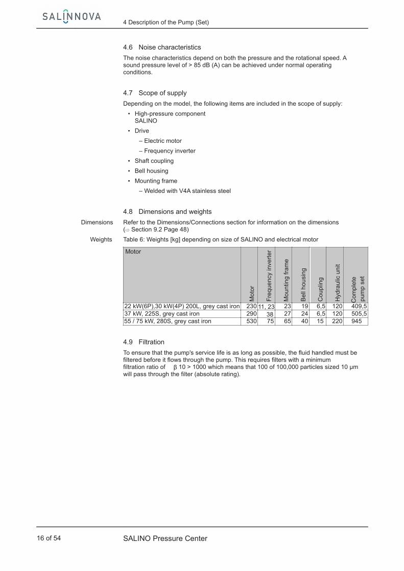
4.8 Dimensions and weights
Refer to the Dimensions/Connections section for information on the dimensions(⇨ Section 9.2 Page 48)
Table 6: Weights [kg] depending on size of SALINO and electrical motor
MotorM
oto
r
Fre
que
ncy
inve
rter
Mo
untin
g fr
ame
Bel
l hou
sing
Cou
plin
g
Hyd
raul
ic u
nit
Com
plet
ep
ump
set
22 kW(6P),30 kW(4P) 200L, grey cast iron 230 11, 23 23 19 6,5 120 409,537 kW, 225S, grey cast iron 290 38 27 24 6,5 120 505,5
55 / 75 kW, 280S, grey cast iron 530 75 65 40 15 220 945
4.9 Filtration
To ensure that the pump's service life is as long as possible, the fluid handled must befiltered before it flows through the pump. This requires filters with a minimumfiltration ratio of β 10 > 1000 which means that 100 of 100,000 particles sized 10 µmwill pass through the filter (absolute rating).
Dimensions
Weights
4 Description of the Pump (Set)
16 of 54 SALINO Pressure Center

5 Installation at Site
5.1 Safety regulations
DANGER
Installation in potentially explosive atmospheresExplosion hazard!
▷ Never install the pump in potentially explosive atmospheres.
▷ Observe the information given in the data sheet and on the name plates of thepump system.
DANGER
Improper transportRisk of injury from lifting heavy components!
▷ Select lifting accessories which are suitable for the component weight.
▷ Always use the attachment points provided for the lifting accessories.
▷ Comply with the applicable health and safety regulations.
DANGER
The pump or individual components could slip out of the suspension arrangementDanger to life from falling parts!
▷ Always transport the pump or components in the specified position.
▷ Never attach the suspension arrangement to the free shaft end of the pump.
▷ Refer to the weight of the individual components and the centre of gravity.
▷ Observe the applicable local accident prevention regulations.
▷ Use suitable, permitted lifting accessories, e.g. self-tightening lifting tongs.
5.2 Checks to be carried out prior to installation
Place of installation
WARNING
Installation on mounting surfaces which are unsecured and cannot support the loadPersonal injury and damage to property!
▷ Use a concrete of compressive strength class C12/15 which meets therequirements of exposure class XS1 to EN 206-1.
▷ The mounting surface must have set and must be completely horizontal andeven.
▷ Observe the weights indicated.
1. Check the structural requirements. All structural work required must have been prepared in accordance with thedimensions. (⇨ Section 9.2 Page 48)
CAUTIONImproper installation of the pump setDamage to property!
▷ The pump set must be installed in an enclosed room and protected fromadverse environmental conditions.
5 Installation at Site
SALINO Pressure Center 17 of 54

NOTEThe pump set is most efficiently operated at temperatures of between +5 °C and+40 °C and with an atmospheric humidity of under 50 %.
CAUTIONUse of the pump in adverse ambient conditionsDamage to property!
▷ Never operate the pump set in ambient conditions other than those described.
5.3 Installing the pump set
Always install the pump set in a horizontal position.
When installing the pump set, also observe the chapter on Dimensions/Connections.(⇨ Section 9.2 Page 48)
WARNING
Excessive temperatures due to improper installationRisk of burns!Damage to the pump!
▷ Install the pump in a horizontal position to ensure self-venting of the pump.
NOTEWhen installing the system, ensure that sufficient space is available around thepump set to facilitate servicing and maintenance.
5.3.1 Installation on a foundation
3
4
Fig. 5: SALINO – installation on a foundation
L1
32
Fig. 6: Shims to compensate imbalance for installation on a foundation
L Bolt-to-bolt distance1 Shims 2 Additional shims3 Foundation bolt 4 Fastening screw
✓ The foundation has the required strength and characteristics.
5 Installation at Site
18 of 54 SALINO Pressure Center

✓ The foundation has been prepared in accordance with the dimensions andconnections. ( ⇨ Section 9.2 Page 48)
1. Place the pump set including mounting frame on the foundation and alignusing a spirit level.
2. Use shims (1) and additional shims (2) (if the distance (L) between thefoundation bolts is > 800 mm) for height compensation if necessary.Always fit shims immediately to the left and right of the foundation bolts (3)between the mounting frame and the foundation. All shims must lie perfectlyflush.
3. Insert the foundation bolts (3) into the holes provided.
4. Use concrete to set the foundation bolts (3) into the foundation.
5. Wait until the concrete has set firmly, then level the mounting frame.
6. Loosen the fastening screw (4) at the pump support without removing it.
7. Tighten the foundation bolts (3) evenly and firmly.
8. Firmly tighten the fastening screw (4) at the pump support.
Table 7: Size of foundation bolts depending on the unit size
Size Foundation bolt size14 M1220 M1223 M18
NOTETo install the pump set on a support structure it is also possible to use the holesprovided in the mounting frame.
5.4 Pipes/hoses
5.4.1 Properly connecting pipes/hoses
DANGER
Impermissible loads acting on the mating flanges.Danger to life from leakage of hot, toxic, corrosive or flammable fluids!
▷ Do not use the pump as an anchorage point for the piping.
▷ Anchor the pipes in close proximity to the pump and connect withouttransmitting any stresses or strains using hoses.
▷ Take appropriate measures to compensate for thermal expansion of the piping.
CAUTIONContamination/dirt in the pipingDamage to the pump! Any rust in the pipework will lead to no warranty for SALINO.
▷ Clean the piping and check for contamination before connecting to the pump.
NOTEWhenever modifications to the system (e.g. installation of fittings) are performed,always clean the piping avoiding that dirt can enter the pump.
5 Installation at Site
SALINO Pressure Center 19 of 54

CAUTIONIncorrect earthing during welding work at the pipingDestruction of rolling element bearings (pitting effect)!
▷ Never earth the electric welding equipment on the pump or baseplate.
▷ Prevent current flowing through the rolling element bearings.
NOTEInstalling check and shut-off elements in the system is recommended, depending onthe type of plant and pump. However, such elements must not obstruct properdrainage or hinder disassembly of the pump.
CAUTIONDry running of the mechanical seal/pump malfunctionDamage to the pump!
▷ The connection lines must be laid in such a manner that no air pockets canform.
▷ The connection lines must be tightly sealed.
▷ In order that the approach flow conditions and thus the NPSH of the system arenot impaired, avoid installing narrow elbows and valves directly upstream ofthe pump.
✓ The nominal diameters of the pipes are equal to or greater than the nominaldiameters of the pump nozzles.
✓ Adapters to larger nominal diameters are designed with a diffuser angle ofapprox. 8° to avoid excessive pressure losses.
✓ The hoses have been connected without transmitting any stresses or strains.
✓ The filters have been installed properly.
✓ Throttling or shut-off elements have not been installed in the drain lines.
NOTEThe drained liquid from the pump (but not that of the energy recovery device) canbe discharged into an unpressurised feed water tank (if fitted).
NOTEWe recommend installing a gate valve or a swing check valve in the inlet ordischarge line, either directly upstream or downstream of the pump. This preventsthe fluid handled from flowing back if the pump is stopped or removed forservicing and maintenance. During pump operation these gate valves must be fullyopen and not used for flow control. Operation against a closed gate valve willinevitably lead to damage to the pump/system.
1. Thoroughly clean, flush and blow air through tanks, pipes, hoses andconnections.
2. Before installing the pump in the system, remove the flange covers of the inletand outlet connections.
CAUTIONWelding beads, scale and other impurities in the pipingDamage to the pump!
▷ Remove any impurities from the piping.
▷ If necessary, install a filter.
3. If required, install a filter in the piping (see drawing: Filter in the piping).
5 Installation at Site
20 of 54 SALINO Pressure Center

1
2
Fig. 7: Filter in the piping
1 Differential pressure gauge 2 Filter
CAUTIONPressure drop between pressure sensor and pump inletDamage to the pump!
▷ Never install pressure-reducing components (e.g. filters) between the inletpressure monitoring sensor and the pump inlet.
▷ Position the pressure sensor in close proximity to the pump inlet.
CAUTIONFormation of air bubbles in the pipes during standstill and with the bypass valveopen.Damage to the machinery!Damage to the pump and membranes!
▷ Secure open inlets and outlets to prevent the fluid handled from escaping.
4. Install the bypass valve and drain lines at the highest position in the system.(⇨ Section 4.5 Page 14)
5. Connect the pump nozzles to the pipes via hoses. ( ⇨ Section 9.2 Page 48)
CAUTIONAggressive flushing, cleaning and pickling agentsDamage to the pump!
▷ Match the cleaning operation mode and duration of flushing and pickling tothe casing and seal materials used.
5.5 Protective equipment
5.5.1 Mounting the coupling guard
WARNING
Failure to re-install or re-activate protective devicesRisk of injury from moving parts or escaping fluid!
▷ As soon as the work is completed, re-install and/or re-activate any safety-relevant and protective devices.
5 Installation at Site
SALINO Pressure Center 21 of 54

WARNING
Unprotected rotating couplingRisk of injury by rotating shafts!
▷ Always operate the pump set with a coupling guard.If the customer specifically requests not to include a coupling guard in KSB'sdelivery, then the operator must supply one!
▷ Observe all relevant regulations for selecting a coupling guard.
As standard, the pump set is supplied with a bell housing which serves as a couplingguard. If a different configuration is used, ensure an appropriate coupling guard isfitted.
5.5.2 Fitting the pressure sensors
CAUTIONPressure drop at the pump inlet and the energy recovery device's outletDamage to the pump!
▷ Fit the pressure sensor as close as possible to the connections to be monitored.
▷ Continuous pressure monitoring and definition as shutdown condition in thesystem's control unit.
▷ Observe the operating limits.
✓ The pressure sensors meet the application's requirements.(corrosion resistance, atmospheric humidity, measurable pressure range)
✓ Pressure-reducing components (e.g. filters) have not been installed between theinlet pressure monitoring sensor and the pump inlet.
1. Fit pressure sensors as close as possible to the connection to be monitored.
5.5.3 Installing the temperature monitoring devices
CAUTIONExceeding or dropping below the permissible fluid temperaturesDamage to the pump!
▷ Continuous temperature monitoring at both inlet connections and definition asshutdown condition in the system's control unit.
▷ Observe the operating limits.
✓ The temperature sensors meet the application's requirements.(corrosion resistance, atmospheric humidity, measurable temperature range)
1. Install the temperature sensors in close proximity to the connection to bemonitored.
5.5.4 Installing the pressure relief valve
WARNING
Incorrect setting of the pressure relief valve
Personal injury and damage to property!Pump malfunction!
▷ The pressure relief valve must be set by the operator to match the respectiveapplication as its error-free functioning (correct fluid discharge) depends on thepump's speed/flow rate and the fluid's density and viscosity.
5 Installation at Site
22 of 54 SALINO Pressure Center

NOTEThe use of a safety valve is always recommended in order to ensure the pump'sreliability in the event that an operator's error causes excess pressure peaks.
NOTEThe safety valve ensures the fluid handled is discharged from the high-pressuresection of the system thus preventing excess pressure. The valve is spring-loaded.The valve must be set to the maximum system pressure.
1. Properly install the pressure relief valve.
2. Set the pressure relief valve as specified.
5.6 Checking the coupling alignment
CAUTIONImpermissible radial or axial loads at the drive shaftDamage to the machinery!
▷ Observe the manufacturer's coupling alignment instructions.
A B
Fig. 8: Checking the coupling alignment
A Drive-end reference dimensionB Pump-end reference dimension
Table 8: Reference dimension "A" depending on the motor
Motor A
[mm]22/30 kW, 200L, grey cast iron 11037 kW, 225S, grey cast iron 14055 / 75 kW, 280S, grey cast iron 140
Table 9: Reference dimension "B" depending on the pump size
Size B
[mm]14/20 11423 11468 114
Drive end
NOTEThe coupling is shrink-fitted and aligned at the factory. If other couplingcomponents are used, ensure that they are aligned properly.
5 Installation at Site
SALINO Pressure Center 23 of 54

Pump end
CAUTIONImpermissible distance between the coupling halvesDamage to the machinery!
▷ Always observe the specified dimensions for the alignment of the pump'scoupling halves.
NOTEThe dimensions refer to the bell housing supplied by Salinnova. The specified fittingdimensions only apply for this bell housing!
5.7 Electrical system
5.7.1 Frequency inverter operation
The pump set can only be operated with a frequency inverter.
When selecting a frequency inverter, check the following details:
▪ Data provided by the manufacturer
▪ Electrical data of the pump set, particularly the rated current
Observe the following limits during operation on a frequency inverter:
▪ Only utilise up to 95 % of the motor rating indicated on the data sheet.
▪ Do not exceed the maximum pump speed (depending on its size).
5.7.2 Electrical connection
DANGER
Electrical connection work by unqualified personnelDanger of death from electric shock!
▷ Always have the electrical connections installed by a trained and qualifiedelectrician.
▷ Observe regulations IEC 60364 and, for explosion-proof models, IEC 60079.
▷ Observe the motor and frequency inverter operating manuals.
WARNING
Unintentional starting of pump setRisk of injury by moving parts!
▷ Ensure that the pump set cannot be started up unintentionally.
▷ Always make sure the electrical connections are disconnected before carryingout work on the pump set.
WARNING
Incorrect connection to the mainsDamage to the mains network, short circuit!
▷ Observe the technical specifications of the local energy supply companies.
1. Check the available mains voltage against the data on the name plate.
2. Select an appropriate start-up method.
Selection
Operation
5 Installation at Site
24 of 54 SALINO Pressure Center
NOTEA motor protection device is recommended.
5.7.2.1 Connecting the motor
NOTEIn compliance with IEC 60034-8, three-phase motors are always wired for clockwiserotation (looking at the motor shaft stub).The pump's direction of rotation is indicated by an arrow on the pump.
1. Match the motor's direction of rotation to that of the pump.
2. Observe the manufacturer's product literature supplied with the motor.
5.7.2.2 Earthing
DANGER
Electrostatic chargingExplosion hazard!Fire hazard!Damage to the pump set!
▷ Connect the PE conductor to the earthing terminal provided.
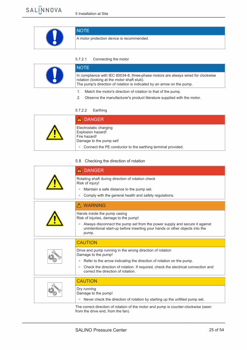
5.8 Checking the direction of rotation
DANGER
Rotating shaft during direction of rotation checkRisk of injury!
▷ Maintain a safe distance to the pump set.
▷ Comply with the general health and safety regulations.
WARNING
Hands inside the pump casingRisk of injuries, damage to the pump!
▷ Always disconnect the pump set from the power supply and secure it againstunintentional start-up before inserting your hands or other objects into thepump.
CAUTIONDrive and pump running in the wrong direction of rotationDamage to the pump!
▷ Refer to the arrow indicating the direction of rotation on the pump.
▷ Check the direction of rotation. If required, check the electrical connection andcorrect the direction of rotation.
CAUTIONDry runningDamage to the pump!
▷ Never check the direction of rotation by starting up the unfilled pump set.
The correct direction of rotation of the motor and pump is counter-clockwise (seenfrom the drive end, from the fan).
5 Installation at Site
SALINO Pressure Center 25 of 54
1. Start the motor and stop it again immediately (< 1 second) to determine themotor's direction of rotation via the motor's fan.
⇨ The motor's direction of rotation must match the arrow indicating thedirection of rotation on the pump.
2. If the motor is running in the wrong direction of rotation, check the electricalconnection of the motor and the control system, if applicable.
5 Installation at Site
26 of 54 SALINO Pressure Center

6 Commissioning/Start-up/Shutdown
6.1 Commissioning/start-up
6.1.1 Prerequisites for commissioning/start-up
Before commissioning/starting up the pump set, make sure that the followingconditions are met:
▪ The pump set has been connected with low-pressure and high-pressure hoses asdescribed.
▪ The high-pressure and low-pressure hoses have been connected to the matingflanges without transmitting any stresses or strains.
▪ All screwed connections have been tightened properly.
▪ The mounting frame has been properly fitted to the base frame or foundation.
▪ The pump with the integrated energy recovery device and the membranes havebeen primed with the fluid handled.
▪ The direction of rotation has been checked.
▪ The pump set has been installed in the system in compliance with theregulations.
▪ After prolonged shutdown of the pump (set), the activities required for returningthe pump (set) to service have been carried out. ( ⇨ Section 6.4 Page 35)
6.1.2 Priming and venting the pump
WARNING
Shaft seal failure caused by insufficient lubricationLeakage of toxic fluid handled!
▷ Before pump start-up, vent the pump and inlet line and prime both with thefluid to be handled.
CAUTIONIncreased wear due to dry runningDamage to the pump set!
▷ Never operate the pump set without a liquid fill.
▷ Never close the shut-off element in the inlet line and/or supply line duringpump operation.
1. Vent the pump and the inlet lines and prime both with the pretreated fluid.
2. Prime the high-pressure piping system, membranes and integrated energyrecovery device of the pump with pretreated fluid handled.
NOTEFor design-inherent reasons some unfilled volume in the hydraulic system cannot beexcluded after the pump has been primed for commissioning/start-up. However,once the motor is started up the pumping effect will immediately fill this volumewith the fluid handled.
6 Commissioning/Start-up/Shutdown
SALINO Pressure Center 27 of 54

6.1.3 Start-up
DANGER
Non-compliance with the permissible pressure and temperature limits due to closedinlet, discharge or outlet linesPersonal injury and damage to property!Leakage of hot or toxic fluids!
▷ Never start up or operate the pump with the shut-off elements in the inlet,discharge or outlet lines closed.
▷ Only start up the pump set against a fully open inlet-side, discharge-side oroutlet-side shut-off element.
DANGER
Excessive temperatures due to dry-runningRisk of injury!Damage to the pump set!
▷ Never operate the pump set without a liquid fill.
▷ Prime the pump as per operating instructions.
▷ Always operate the pump within the permissible operating range.
WARNING
Pump sets with high noise levelsDamage to hearing!
▷ Persons must only enter the vicinity of the running pump set if they are wearingprotective equipment/ear protection.
▷ See noise characteristics.
CAUTIONAbnormal noises, vibrations, temperatures or leakageDamage to the pump!
▷ Switch off the pump (set) immediately.
▷ Eliminate the causes before returning the pump set to service.
✓ The piping in the system has been cleaned.
✓ Pump, inlet pipe system and discharge pipe system (and inlet tank if fitted) havebeen vented and primed with the fluid to be handled.
✓ The priming pipes and vent pipes have been closed.
WARNING
Start-up and operation of pump against closed discharge linePersonal injury and damage to property!
▷ Never operate the pump with the discharge line closed. Pumping against aclosed shut-off element will result in overheating and a direct and suddenpressure increase.
▷ Install a pressure relief valve upstream of a shut-off element.
1. Fully open the shut-off elements in the inlet pipe.
2. Fully open the shut-off elements in the discharge pipe.
3. Fully open the shut-off elements in the outlet pipe.
4. Fully open the bypass valve.
⇨ The required inlet pressure is available at the pump inlet.
6 Commissioning/Start-up/Shutdown
28 of 54 SALINO Pressure Center

CAUTIONInsufficient inlet pressure at the pump inletDamage to the pump due to cavitation!
▷ Never operate the pump below the specified inlet pressure required at thepump inlet.
5. Start up the motor and run up to an initial speed of 100 rpm.Ensure short start ramps (5 seconds). Increase to 200 rpm, if drainage is visible.
CAUTIONInsufficient back pressure at the energy recovery device's outletDamage to the energy recovery device due to cavitation!
▷ For speeds ≥ 600 rpm, never operate the pump below the specified backpressure at the energy recovery device's outlet.
⇨ The required back pressure is available at the energy recovery device's outlet.
6. If required, vent again.
7. Slowly close the bypass valve at 100 rpm
8. Slowly increase the speed up to the rated speed or necessary feed volume flowrate.Observe the maximum flow increase per second specified in the membranes'operating manual.
NOTEBefore the motor has run up to the required speed, check for possible faults(pressure overload, cavitation, vibrations, etc.).
n [m
in-1]
Fig. 9: Start-up procedure diagram
Table 10: Start-up procedure (please refer to page 15)
Time Control To be checked/ to be done t1 – t0 Start feed pump, wait for 30 sec., start Salino at
100 rpm, for approx. 1 minute Air vents at drainage lines? Close by pass valve.
t2 - t1 Increase speed to 200 upto 600 rpm in 30 sec. Drainage visible? Suction pressure to be
t2 600 rpm are achieved? Maintain.
to pick up, back pressure approx. 3 bar t3 - t2 Maintain 600 rpm for 1 min Suction pressure min. 2,5, discharge pressure
t3 Maintain 600 rpm Discharge Pressure picks up. Drainage visible?Read suction , discharge and back pressure
6 Commissioning/Start-up/Shutdown
SALINO Pressure Center 29 of 54
Suction pressure, discharge and back pressure
Checked, same for back pressure

Time Control To be checked / to be donet4 - t3 Maintain 600 rpm for further 2 min Suction pressure to drop not less than 2,5 bar
Discharge pressure 10bar? Back pressure 3bar?t4 Maintain 600 rpm Discharge pressure can reach 50 bar.t5 Increase speed to rated speed, 200 rpm/15 sec t6 - t5 Ramp from 600 rpm to nominal speed,
observing membrane specificationsSuction pressure 2,5 bar? Discharge pressureIs rated pressure? Back pressure 3 bar?
t6 Maintain duty point
6.1.4 Shutdown
WARNING
Start-up and operation of pump against closed discharge linePersonal injury and damage to property!
▷ Never operate the pump with the discharge line closed. Pumping against aclosed shut-off element will result in overheating and a direct and suddenpressure increase.
▷ Install a pressure relief valve upstream of a shut-off element.
1. Slowly reduce the speed to speed of 600 rpm.
2. Slowly reduce speed to 200, than 100 rpm.
3. Shut down SALINO.
4. Shut down the booster pump. Open bypass valve for 5 sec., then close it again.
CAUTIONIncreased corrosion risk due to standing salt water/brine in the pumpDamage to the pump due to corrosion!
▷ Sufficiently flush the pump set with permeate before prolonged shutdownperiods.
5. Start flushing process using permeate/tap water (start up flushing pump).
6. Have SALINO rotate at a speed of 600 rpm along with the flushing pump.
NOTESalinnovas recommends a flushing period of 5 minutes for the pump set only.
7. Shut down SALINO.
8. Stop the flushing process by shutting down the flushing pump.
CAUTIONRisk of freezing during prolonged pump shutdown periodsDamage to the pump!
▷ Drain the pump and the cooling/heating chambers (if any) or otherwise protectthem against freezing.
6 Commissioning/Start-up/Shutdown
30 of 54 SALINO Pressure Center
Suction pressure 2,5 bar? Back pressure 3 bar?
0
10
20
30
40
50
60
70
80
90
0
200
400
600
800
1000
1200
1400
1600
1800
0 t1 t2 t3 t4 t5
p [b
ar]
n [m
in-1]
t
n p
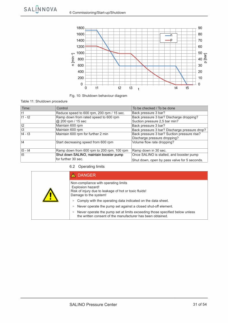
Fig. 10: Shutdown behaviour diagram
Table 11: Shutdown procedure
Time: Control To be checked / To be donet1 Reduce speed to 600 rpm, 200 rpm / 15 sec. t1 - t2 Ramp down from rated speed to 600 rpm
@ 200 rpm / 15 secBack pressure 3 bar? Discharge dropping? Suction pressure 2,5 bar min?
t2 Maintain 600 rpm t3 Maintain 600 rpm t4 - t3 Maintain 600 rpm for further 2 min Back pressure 3 bar? Suction pressure rise?
Discharge pressure dropping?t4 Start decreasing speed from 600 rpm Volume flow rate dropping?
t5 - t4 Ramp down from 600 rpm to 200 rpm, 100 rpm Ramp down in 30 sec.t5 Shut down SALINO, maintain booster pump Once SALINO is stalled, and booster pump
6.2 Operating limits
DANGER
Non-compliance with operating limitsExplosion hazard!
Risk of injury due to leakage of hot or toxic fluids!Damage to the system!
▷ Comply with the operating data indicated on the data sheet.
▷ Never operate the pump set against a closed shut-off element.
▷ Never operate the pump set at limits exceeding those specified below unlessthe written consent of the manufacturer has been obtained.
6 Commissioning/Start-up/Shutdown
SALINO Pressure Center 31 of 54
Back pressure 3 bar?
Back pressure 3 bar?Back pressure 3 bar? Discharge pressure drop?
Shut down SALINO, maintain booster pump for further 30 sec. Shut down, open by pass valve for 5 seconds.

6.2.1 Pressures
6.2.1.1 Inlet pressure
CAUTIONFalling below the permissible inlet pressure at the pump inletDamage to the pump set due to cavitation!
▷ Never close shut-off elements in the inlet pipe or install throttling elements inthe inlet pipe.
▷ Continuous inlet pressure monitoring and definition as cut-out condition in thesystem's control unit.
▷ Do not install pressure-reducing components (e.g. filters) between the inletpressure monitoring sensor and the pump inlet.
▷ Position the pressure sensor in close proximity to the pump inlet.
Table 12: Inlet pressure [bar] depending on size
Size Limits Warning Shutdown
Min. Max. Min. Max. Min. Max.14 2,5 10,0 2,3 9,0 2,0 10,020 3,0 10,0 2,8 9,0 2,5 10,065 3,5 10,0 3,3 9,0 3,0 10,0
The sum of inlet pressure and differential pressure must not exceed 100 bar.
The 100 bar limit refers to the pump only.The maximum differential pressure of 70 bar refers to the pump set.
For higher differential pressures the motor rating must be matched accordingly.
6.2.1.2 Operating pressure
DANGER
Non-compliance with permissible operating pressureDamage to the pump set!Damage to the system!Risk of injury!
▷ Never close the shut-off elements during operation.
▷ Check the membranes' condition and clean or replace if required.
▷ Set the pressure relief valve to the maximum system pressure.
Table 13: Operating pressure 1) [bar]
Size Limits Warning Shutdown
Min. Max. Min. Max. Min. Max.All 30,0 100,0 32,0 95,0 30,0 100,0
The sum of inlet pressure and differential pressure must not exceed 100 bar.
The 100 bar limit refers to the pump only.The maximum differential pressure of 70 bar refers to the pump set.
For higher differential pressures the motor rating must be matched accordingly.
1) All components used in the high-pressure section must be designed to withstand the maximum operating pressure.
6 Commissioning/Start-up/Shutdown
32 of 54 SALINO Pressure Center
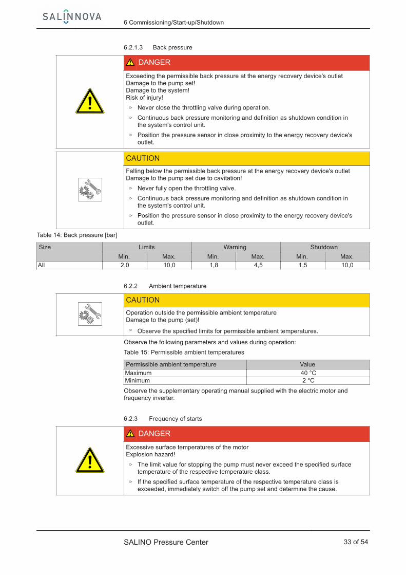
6.2.1.3 Back pressure
DANGER
Exceeding the permissible back pressure at the energy recovery device's outletDamage to the pump set!Damage to the system!Risk of injury!
▷ Never close the throttling valve during operation.
▷ Continuous back pressure monitoring and definition as shutdown condition inthe system's control unit.
▷ Position the pressure sensor in close proximity to the energy recovery device'soutlet.
CAUTIONFalling below the permissible back pressure at the energy recovery device's outletDamage to the pump set due to cavitation!
▷ Never fully open the throttling valve.
▷ Continuous back pressure monitoring and definition as shutdown condition inthe system's control unit.
▷ Position the pressure sensor in close proximity to the energy recovery device'soutlet.
Table 14: Back pressure [bar]
Size Limits Warning Shutdown
Min. Max. Min. Max. Min. Max.All 2,0 10,0 1,8 4,5 1,5 10,0
6.2.2 Ambient temperature
CAUTIONOperation outside the permissible ambient temperatureDamage to the pump (set)!
▷ Observe the specified limits for permissible ambient temperatures.
Observe the following parameters and values during operation:
Table 15: Permissible ambient temperatures
Permissible ambient temperature ValueMaximum 40 °CMinimum 2 °C
Observe the supplementary operating manual supplied with the electric motor andfrequency inverter.
6.2.3 Frequency of starts
DANGER
Excessive surface temperatures of the motorExplosion hazard!
▷ The limit value for stopping the pump must never exceed the specified surfacetemperature of the respective temperature class.
▷ If the specified surface temperature of the respective temperature class isexceeded, immediately switch off the pump set and determine the cause.
6 Commissioning/Start-up/Shutdown
SALINO Pressure Center 33 of 54
The frequency of starts is usually determined by the maximum temperature increaseof the motor. This largely depends on the power reserves of the motor in steady-state operation and on the starting conditions (DOL, star-delta, moments of inertia,etc). If the start-ups are evenly spaced over the period indicated, the pump set can bestarted up six times per hour (h).
CAUTIONRe-starting while motor is still running downDamage to the pump (set)!
▷ Do not re-start the pump set before the pump rotor has come to a standstill.
6.2.4 Fluid handled
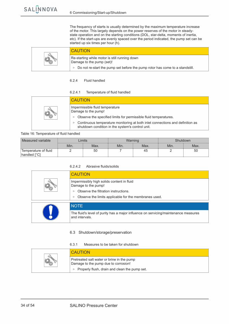
6.2.4.1 Temperature of fluid handled
CAUTIONImpermissible fluid temperatureDamage to the pump!
▷ Observe the specified limits for permissible fluid temperatures.
▷ Continuous temperature monitoring at both inlet connections and definition asshutdown condition in the system's control unit.
Table 16: Temperature of fluid handled
Measured variable Limits Warning Shutdown
Min. Max. Min. Max. Min. Max.Temperature of fluidhandled [°C]
2 50 7 45 2 50
6.2.4.2 Abrasive fluids/solids
CAUTIONImpermissibly high solids content in fluidDamage to the pump!
▷ Observe the filtration instructions.
▷ Observe the limits applicable for the membranes used.
NOTEThe fluid's level of purity has a major influence on servicing/maintenance measuresand intervals.
6.3 Shutdown/storage/preservation
6.3.1 Measures to be taken for shutdown
CAUTIONPretreated salt water or brine in the pumpDamage to the pump due to corrosion!
▷ Properly flush, drain and clean the pump set.
6 Commissioning/Start-up/Shutdown
34 of 54 SALINO Pressure Center

The pump (set) remains installed
✓ Sufficient fluid in the form of either drinking, tap or service water is suppliedfor the operation check run of the pump.
1. For prolonged shutdown periods, regularly start up the pump set between oncea month and once every three months for approximately five minutes at thespecified inlet pressure, with the bypass valve open and at a speed of 600 rpm.
⇨ After shutting down SALINO, the booster pump can be switched off.
⇨ This will prevent the formation of deposits within the pump and the pumpintake area.
The pump (set) is removed from the piping and stored
✓ The pump has been properly flushed with drinking, tap or service water, anddrained. ( ⇨ Section 6.1.4 Page 30) (⇨ Section 7.3 Page 39)
✓ The safety instructions for dismantling the pump have been observed.(⇨ Section 7.4.1 Page 39)
1. Close the pump set's connections (e.g. with plastic caps or similar).
2. Store the pump in a dry and protected place at room temperature (approx.20 °C).
6.4 Returning to service
For returning the pump to service, observe the sections on commissioning/start-up(⇨ Section 6.1 Page 27) and the operating limits .
In addition, carry out all servicing/maintenance operations before returning thepump (set) to service. ( ⇨ Section 7 Page 36)
WARNING
Failure to re-install or re-activate protective devicesRisk of personal injury from moving parts or escaping fluid!
▷ As soon as the work is complete, re-install and/or re-activate any safety-relevantand protective devices.
NOTEIf the pump has been out of service for more than one year, replace all elastomerseals.
6 Commissioning/Start-up/Shutdown
SALINO Pressure Center 35 of 54

7 Servicing/Maintenance
7.1 Safety regulations
DANGER
Insufficient preparation of work on the pump (set)Risk of injury!
▷ Properly shut down the pump set.
▷ Close the shut-off elements in inlet, discharge and outlet lines.
▷ Drain the pump and release the pump pressure.
▷ Shut off any auxiliary feed lines.
▷ Allow the pump set to cool down to ambient temperature.
▷ Ensure the pump set is secured against tipping over, especially on wet floors.
DANGER
Improperly serviced pump setExplosion hazard!Damage to the pump set!
▷ Service the pump set regularly.
▷ Prepare a maintenance schedule with special emphasis on shaft seal andcoupling.
The operator ensures that maintenance, inspection and installation is performed byauthorised, qualified specialist personnel who are thoroughly familiar with themanual.
WARNING
Liquids escaping at high pressureRisk of injury!
▷ Depressurise the pump.
WARNING
Unintentional starting of pump setRisk of injury by moving parts!
▷ Ensure that the pump set cannot be started up unintentionally.
▷ Always make sure the electrical connections are disconnected before carryingout work on the pump set.
WARNING
Fluids, consumables and supplies which are hot and/or pose a health hazardRisk of injury!
▷ Observe all relevant laws.
▷ When draining the fluid take appropriate measures to protect persons and theenvironment.
▷ Decontaminate pumps which handle fluids posing a health hazard.
WARNING
Insufficient stabilityRisk of crushing hands and feet!
▷ During assembly/dismantling, secure the pump (set)/pump parts to preventtipping or falling over.
7 Servicing/Maintenance
36 of 54 SALINO Pressure Center

A regular maintenance schedule will help avoid expensive repairs and contribute totrouble-free, reliable operation of the pump, pump set and pump parts with aminimum of servicing/maintenance expenditure and work.
NOTEAll maintenance, service and installation work can be carried out by KSB Service orauthorised workshops. For contact details please refer to the enclosed "Addresses"booklet or visit "www.salinnova.com" on the Internet.
Never use force when dismantling and reassembling the pump set.
WARNING
Failure to re-install or re-activate protective devicesRisk of injury from moving parts or escaping fluid!
▷ As soon as the work is completed, re-install and/or re-activate any safety-relevant and protective devices.
7.2 Servicing/inspection
7.2.1 Supervision of operation
DANGER
Non-compliance with permissible operating pressureDamage to the pump set!Damage to the system!Risk of injury!
▷ Never close the shut-off elements during operation.
▷ Check the membranes' condition and clean or replace if required.
▷ Set the pressure relief valve to the maximum system pressure.
DANGER
Excessive temperatures due to dry-runningRisk of injury!Damage to the pump set!
▷ Never operate the pump set without a liquid fill.
▷ Prime the pump as per operating instructions.
▷ Always operate the pump within the permissible operating range.
CAUTIONImpermissible fluid temperatureDamage to the pump!
▷ Observe the specified limits for permissible fluid temperatures.
▷ Continuous temperature monitoring at both inlet connections and definition asshutdown condition in the system's control unit.
CAUTIONExcessively high pressure at the drain connectionDamage to the pump!
▷ Never install throttling elements in the drain line.
▷ Ensure that the fluid drained is under as little pressure as possible.
7 Servicing/Maintenance
SALINO Pressure Center 37 of 54
CAUTIONPressure drop at the pump inlet and the energy recovery device's outletDamage to the pump due to cavitation!
▷ Fit the pressure sensor as close as possible to the connections to be monitored.
▷ Continuous temperature monitoring and definition as shutdown condition inthe system's control unit.
▷ Observe the operating limits.
While the pump is in operation, observe and check the following:
▪ The pump must run quietly and free from vibrations at all times.
▪ Check the static seals for leakage.
▪ Check for running noises. Vibrations, noise and an increase in current inputoccurring during unchanged operating conditions indicate wear.
▪ Monitor the correct functioning of any auxiliary connections.
▪ Monitor the stand-by pump to ensure that it remains ready for operation. Startup the stand-by pumps once a week.
▪ Warning and shutdown values ( ⇨ Section 6.2 Page 31)
7.2.2 Inspection work
7.2.2.1 Checking the coupling
DANGER
Excessive temperatures caused by friction, impact or frictional sparksFire hazard!Damage to the pump set!
▷ Regularly check the coupling guard, plastic components and other guards ofrotating parts for deformation and sufficient distance from rotating parts.
Check the flexible elements of the coupling. Replace the relevant parts in due time ifthere is any sign of wear and check the alignment.
Observe the manufacturer's product literature supplied with the coupling.
7.2.2.2 Cleaning filters
CAUTIONInsufficient inlet pressure due to clogged filter in the inlet lineDamage to the pump!
▷ Monitor contamination of filter with suitable means (e.g. differential pressuregauge).
▷ Clean filters at appropriate intervals.
7.2.3 Lubrication and lubricant change
DANGER
Excessive temperatures as a result of bearings running hot or defective bearing sealsFire hazard!Damage to the pump set!
▷ Regularly check the rolling element bearings for running noises.
▷ Observe the electric motor's operating manual.
7 Servicing/Maintenance
38 of 54 SALINO Pressure Center

7.3 Drainage/cleaning
WARNING
Fluids, consumables and supplies which are hot and/or pose a health hazardHazard to persons and the environment!
▷ Collect and properly dispose of flushing fluid and any residues of the fluidhandled.
▷ Wear safety clothing and a protective mask, if required.
▷ Observe all legal regulations on the disposal of fluids posing a health hazard.
CAUTIONPretreated salt water or brine in the pumpDamage to the pump due to corrosion!
▷ Perform flushing as described.
✓ The pump set has been flushed as described.
✓ The pump set is not operating.
✓ The booster pumps are not operating.
✓ The bypass valve has been opened.
1. Secure the pump set against unintentional start-up.
2. Isolate the pump set using shut-off elements.
3. Remove the drain plug.
It is possible to use the pump's "High Pressure Out" and the energy recovery device's"High Pressure In" connections to drain the pump.
7.4 Dismantling the pump set
7.4.1 General information/safety regulations
DANGER
Insufficient preparation of work on the pump (set)Risk of injury!
▷ Properly shut down the pump set.
▷ Close the shut-off elements in inlet, discharge and outlet lines.
▷ Drain the pump and release the pump pressure.
▷ Shut off any auxiliary feed lines.
▷ Allow the pump set to cool down to ambient temperature.
▷ Ensure the pump set is secured against tipping over, especially on wet floors.
WARNING
Unqualified personnel performing work on the pump (set)Risk of injury!
▷ Always have repair and maintenance work performed by specially trained,qualified personnel.
WARNING
Hot surfaceRisk of injury!
▷ Allow the pump set to cool down to ambient temperature.
7 Servicing/Maintenance
SALINO Pressure Center 39 of 54

WARNING
Improper lifting/moving of heavy assemblies or componentsPersonal injury and damage to property!
▷ Use suitable transport devices, lifting equipment and lifting tackle to moveheavy assemblies or components.
WARNING
Unintentional starting of pump setRisk of injury by moving parts!
▷ Ensure that the pump set cannot be started up unintentionally.
▷ Always make sure the electrical connections are disconnected before carryingout work on the pump set.
Observe the general safety instructions and information.
For any work on the motor, observe the instructions of the relevant motormanufacturer.
For dismantling and reassembly refer to the general assembly drawing.
NOTEAll maintenance, service and installation work can be carried out by SALINNOVA orauthorised workshops. For contact details please refer to the enclosed "Addresses"booklet or visit "www.salinnova.com" on the Internet.
7.4.2 Preparing the pump set
✓ The pump has been flushed.
✓ The pump has been drained.
1. De-energise the pump set and secure it against unintentional start-up.
2. Dismantle any auxiliary connections.
7.4.3 Removing the pump set from the piping
1. Disconnect the high-pressure and low-pressure hoses from the inlet, dischargeand outlet lines.
2. Undo the fastening elements between mounting frame and foundation/baseframe.
3. Attach the complete pump set to suitable lifting equipment and remove fromthe system. (⇨ Section 3.2 Page 10)
7.4.4 Dismantling the pump
WARNING
Insufficient stabilityRisk of crushing hands and feet!
▷ During assembly/dismantling, secure the pump (set)/pump parts to preventtipping or falling over.
7 Servicing/Maintenance
40 of 54 SALINO Pressure Center

1. Attach the pump to suitable lifting equipment.
2. Loosen and remove the screws between the pump flange and the bell housing.
3. Loosen the screw between the support foot and SALINO, but do not remove.
4. Turn the pump by 45° and ensure that the lifting tackle is slightly tensioned.
5. Remove the screw between the support foot and SALINO.
6. Loosen the screws at the motor feet, but do not remove.
7. Slightly shift the pump set in the axial direction towards the motor fan.
8. Remove the pump to disconnect it from the motor.
NOTEThe removal of the pump allows the jaw coupling's insert to be checked for wear. Inthe event of signs of wear, replace this part. Observe the manufacturer's productliterature supplied with the coupling.
7.4.5 Removing the mechanical seal
Fig. 11: Dismantling the mechanical seal
7 Servicing/Maintenance
SALINO Pressure Center 41 of 54

✓ The pump is kept in a stable position in a clean and level assembly area.
1. Dismantle the coupling on the pump's drive shaft.
2. Dismantle the seal cover including the mechanical seal's mating ring.
3. Remove the mechanical seal's mating ring from the seal cover.
4. Check the casing cover's static seal.
5. Clean the assembly surfaces and the drive shaft.
6. Pull the complete mechanical seal off the drive shaft.
7.5 Reassembling the pump set
7.5.1 General information/safety regulations
WARNING
Unqualified personnel performing work on the pump (set)Risk of injury!
▷ Always have repair and maintenance work performed by specially trained,qualified personnel.
WARNING
Improper lifting/moving of heavy assemblies or componentsPersonal injury and damage to property!
▷ Use suitable transport devices, lifting equipment and lifting tackle to moveheavy assemblies or components.
WARNING
Insufficient stabilityRisk of crushing hands and feet!
▷ During assembly/dismantling, secure the pump (set)/pump parts to preventtipping or falling over.
CAUTIONImproper reassemblyDamage to the pump!
▷ Reassemble the pump (set) in accordance with the general rules of soundengineering practice.
▷ Use original spare parts only.
Always reassemble the pump in accordance with the corresponding general assemblydrawing.
▪ Always use new O-rings. Never use O-rings that have been glued together frommaterial sold by the metre.
▪ Avoid the use of assembly adhesives, if possible. Match the lubricant to therespective fluid handled (e.g. pretreated seawater) and also observe theinformation given in the membrane operating manual.
For reassembly, tighten all screws and bolts as specified in this manual. ( ⇨ Section 7.6Page 44)
7.5.2 Installing the mechanical seal
The following rules must be observed when installing the mechanical seal:
▪ For installing the mechanical seal, refer to general assembly drawing.
▪ Work cleanly and accurately.
Sequence
O-rings
Assembly adhesives
Tightening torques
7 Servicing/Maintenance
42 of 54 SALINO Pressure Center
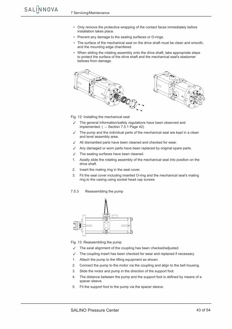
▪ Only remove the protective wrapping of the contact faces immediately beforeinstallation takes place.
▪ Prevent any damage to the sealing surfaces or O-rings.
▪ The surface of the mechanical seal on the drive shaft must be clean and smooth,and the mounting edge chamfered.
▪ When sliding the rotating assembly onto the drive shaft, take appropriate stepsto protect the surface of the drive shaft and the mechanical seal's elastomerbellows from damage.
Fig. 12: Installing the mechanical seal
✓ The general information/safety regulations have been observed andimplemented. ( ⇨ Section 7.5.1 Page 42)
✓ The pump and the individual parts of the mechanical seal are kept in a cleanand level assembly area.
✓ All dismantled parts have been cleaned and checked for wear.
✓ Any damaged or worn parts have been replaced by original spare parts.
✓ The sealing surfaces have been cleaned.
1. Axially slide the rotating assembly of the mechanical seal into position on thedrive shaft.
2. Insert the mating ring in the seal cover.
3. Fit the seal cover including inserted O-ring and the mechanical seal's matingring to the casing using socket head cap screws
7.5.3 Reassembling the pump
Fig. 13: Reassembling the pump
✓ The axial alignment of the coupling has been checked/adjusted.
✓ The coupling insert has been checked for wear and replaced if necessary.
1. Attach the pump to the lifting equipment as shown.
2. Connect the pump to the motor via the coupling and align to the bell housing.
3. Slide the motor and pump in the direction of the support foot.
4. The distance between the pump and the support foot is defined by means of aspacer sleeve.
5. Fit the support foot to the pump via the spacer sleeve.
7 Servicing/Maintenance
SALINO Pressure Center 43 of 54
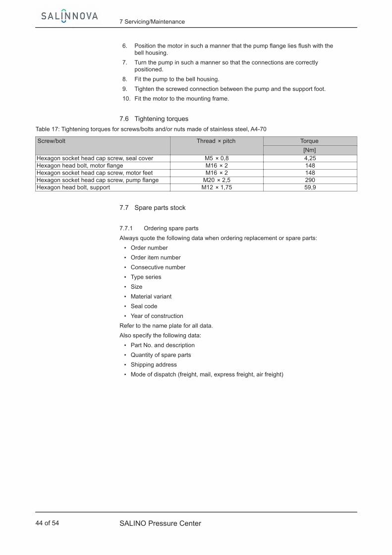
6. Position the motor in such a manner that the pump flange lies flush with thebell housing.
7. Turn the pump in such a manner so that the connections are correctlypositioned.
8. Fit the pump to the bell housing.
9. Tighten the screwed connection between the pump and the support foot.
10. Fit the motor to the mounting frame.
7.6 Tightening torques
Table 17: Tightening torques for screws/bolts and/or nuts made of stainless steel, A4-70
Screw/bolt Thread × pitch Torque
[Nm]Hexagon socket head cap screw, seal cover M5 × 0,8 4,25Hexagon head bolt, motor flange M16 × 2 148Hexagon socket head cap screw, motor feet M16 × 2 148Hexagon socket head cap screw, pump flange M20 × 2,5 290Hexagon head bolt, support M12 × 1,75 59,9
7.7 Spare parts stock
7.7.1 Ordering spare parts
Always quote the following data when ordering replacement or spare parts:
▪ Order number
▪ Order item number
▪ Consecutive number
▪ Type series
▪ Size
▪ Material variant
▪ Seal code
▪ Year of construction
Refer to the name plate for all data.
Also specify the following data:
▪ Part No. and description
▪ Quantity of spare parts
▪ Shipping address
▪ Mode of dispatch (freight, mail, express freight, air freight)
7 Servicing/Maintenance
44 of 54 SALINO Pressure Center

8 Trouble-shooting
WARNING
Improper work to remedy faultsRisk of injury!
▷ For any work to remedy faults observe the relevant information in this manualor in the relevant accessory manufacturer's product literature.
If problems occur that are not described in the following table, consultation with theKSB customer service is required.
Pump is running but does not deliver
Insufficient feed water flow
Insufficient permeate flow
Excessive leakage at the shaft seal
Excessive power input
Unusual vibrations and/or noises
Leakage at the pump
Excessive discharge pressure
Impermissible temperature increase in the pump
Pump discharge pressure is too low
Plain bearing life too short
Mechanical seal life too short
Table 18: Trouble-shooting
A B C D E F G H I J K L Possible cause Remedy- ✘ ✘ ✘ ✘ ✘ - - ✘ - - - Increased leakage due to wear Perform maintenance and replace
worn parts by new ones.✘ - - - ✘ ✘ - - - - - - Clogged inlet pipe or valves in
piping closed or not fully openCheck inlet pipe, remove any foreignparticles and check all valves.
- - - - ✘ - - ✘ - - - - Dirt on the membrane (foulingand/or scaling)
Clean membranes or replace ifrequired.
- - - - ✘ - - ✘ ✘ - - - Change of feed water data (highersalt content, temperature)
Check water data, check suitabilityof selected system.
- - - ✘ - - ✘ - - - - - Dynamic and/or static seal failure Replace mechanical seal, check staticseals and replace by new ones ifrequired.
- - ✘ - - - - - - ✘ - - Open bypass valve Close bypass valve.✘ ✘ ✘ - - - - - - - - - Incorrect pump rotational speed Check rotational speed and correct if
necessary.✘ - - - - ✘ - - - - - - Pump and/or piping are not
completely vented or primed.Vent pump and prime.
- - - - - ✘ - - - - - - Insufficient pump inlet pressure Check inlet pressure and match ifnecessary.
- - - - - ✘ - - - - - - Back pressure too low Check back pressure and matchvalve position if necessary.
- - - - ✘ ✘ - - - - - - Rolling element bearings of motorare worn.
Replace rolling element bearings.
- - - - ✘ - - - - - - - Sympathetic vibrations in the piping Reduce distances between pipeclamps; fasten the pipes using anti-vibration material.
- - - - - ✘ - - - - - - Insufficiently secured pump andpiping system
Check anchoring of pump or pumpset. Support and fasten pipingsufficiently, use expansion joints ifrequired.
- - - - - - - - - - ✘ ✘ Dry running of pump Monitor pump and system (flowmeter, pressure gauge) to preventdry running.
A
B
C
D
E
F
G
H
I
J
K
L
8 Trouble-shooting
SALINO Pressure Center 45 of 54

A B C D E F G H I J K L Possible cause Remedy- - - ✘ - - ✘ - - - ✘ ✘ Solids in the fluid handled Check pretreatment and
prefiltration and repair if required.- - - - ✘ - - - - - - - Speed too high Reduce speed.
8 Trouble-shooting
46 of 54 SALINO Pressure Center

Exploded view and list of components
914.1
412.1
433
213
914.2
562.1562.1
905.1
412.2314
562.2
59-4.1
55-1.1932
562.3
940
50650-3.1
500
471
100
59-3860
540
145920
905.2137
59-3
914.3
130 562.1
914.3130
412.3
914.4137
412.2412.2
914.4
210562.1
412.3100
500562.3
562.2
914.5
920550
412.255-1.2384
50650-3.2
940
59-4.2
SALINO Pressure Center 47 of 54
161.2
161.1
950
950
950

a) b)161.1
545.1
545.3
167.1
161.2
167.2
545.2
Fig. 15: Detailed view: a) Motor end cover b) Pump flange
Table 19: List of components
Part No. Description Part No. Description100 Casing 540 Bush130 Casing part 545.1/.2/.3 Bearing bush137 Control plate 55-1.1/.2 Guide plate145 Adapter 550 Disc161.1/.2 Casing cover 562.1/.2/.3 Parallel pin167.1/.2 Cover insert 59-3 Cylinder210 Shaft 59-4.1/59-4.2 Piston pump / Piston motor213 Drive shaft 860 Coupling part
384 Thrust bearing unit905.1/.2 Tie bolt
412.1/.2/.3 O-ring914.1/.2/.3/.4/.5 Hexagon socket head cap
screw433 Mechanical seal 920 Nut471 Seal cover 932 Circlip50-3.1/.2 Backing ring 940 Key500 Ring 950 Spring506 Retaining ring
9.2 Dimensions and connections
176,1
313
25
1550
595
1248,41254,41394,41516,6
156,
82
93,2
22530
2,5
293,
21
56,8
1248,41254,4
1153,4
820
1672
1597
Fig. 16: Dimensions of SALINO
9 Related Documents
48 of 54 SALINO Pressure Center
314 Thrust bearing with springs
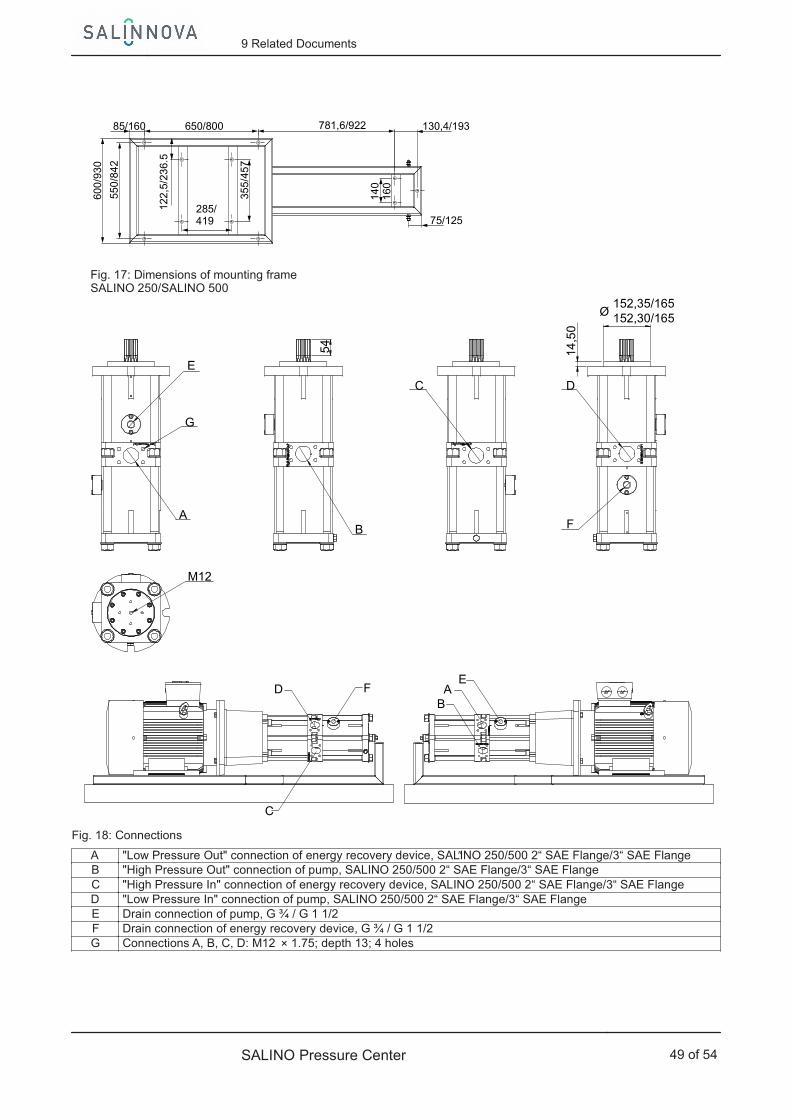
85/160 650/800 781,6/922
600
/93
0
550
/84
2130,4/193
75/125285/419
122
,5/2
36.
5
355
/45
7
140
160
Fig. 17: Dimensions of mounting frameSALINO 250/SALINO 500
M12
G
A
C
B
152,35/165152,30/165
D
Ø
E
F
D F
C
AE
B
14,5
0
54
Fig. 18: Connections
A "Low Pressure Out" connection of energy recovery device, SALINO 250/500 2“ SAE Flange/3“ SAE Flange ″ B "High Pressure Out" connection of pump, SALINO 250/500 2“ SAE Flange/3“ SAE FlangeC "High Pressure In" connection of energy recovery device, SALINO 250/500 2“ SAE Flange/3“ SAE Flange D "Low Pressure In" connection of pump, SALINO 250/500 2“ SAE Flange/3“ SAE FlangeE Drain connection of pump, G ¾ / G 1 1/2F Drain connection of energy recovery device, G ¾ / G 1 1/2G Connections A, B, C, D: M12 × 1.75; depth 13; 4 holes
9 Related Documents
SALINO Pressure Center 49 of 54

10 EC Declaration of Conformity
Manufacturer: SALINNOVA GmbHGutenbergtraße 29
67240 Bobenheim-Roxheim (Germany)
The manufacturer herewith declares that the product:
SALINO Pressure Center
SALINNOVA order number: ...................................................................................................
▪ is in conformity with the provisions of the following Directives as amended from time to time:
– Low-voltage Directive 2006/95/EC
– EC Machinery Directive 2006/42/EC
– "Ecodesign" Directive 2009/125/EC, Regulation No. 640/2009
– Electromagnetic Compatibility Directive 2004/108/EC
The manufacturer also declares that:
▪ the following harmonised international standards have been applied:
– ISO 12100,
– EN 809/ A1
– EN 60034-1:2010, EN 60034-1:2006
– EN 60204-1:2006
– EN 61800-3:2004
– Regulation 640/2009 pertaining to the ecologically compatible design of electric motors
Person authorised to compile the technical file: Name
Function Address (company)Address (Street, No.)Address (post or ZIP code, city) (country)
The EC Declaration of Conformity was issued in/on:
Place, date
..............................2).............................
Name
FunctionCompanyAddress
2) A signed, legally binding declaration of conformity is supplied with the product.
10 EC Declaration of Conformity
50 of 54 SALINO Pressure Center

11 Certificate of Decontamination
Type: ................................................................................................................................Order number/Order item number 3): ................................................................................................................................
Delivery date: ................................................................................................................................ Field of application: ................................................................................................................................ Fluid handled 3): ................................................................................................................................
Please tick where applicable 3):
⃞ ⃞ ⃞ ⃞Radioactive Explosive Corrosive Toxic
⃞ ⃞ ⃞ ⃞Harmful Bio-hazardous Highly flammable Safe
Reason for return 3): ................................................................................................................................
Comments: ................................................................................................................................ ................................................................................................................................
The product/accessories have been carefully drained, cleaned and decontaminated inside and outside prior to dispatch/placing at your disposal.
We herewith declare that this product is free from hazardous chemicals, biological and radioactive substances.
For mag-drive pumps, the inner rotor unit (impeller, casing cover, bearing ring carrier, plain bearing, inner rotor) has beenremoved from the pump and cleaned. In cases of containment shroud leakage, the outer rotor, bearing bracket lantern,leakage barrier and bearing bracket or intermediate piece have also been cleaned.
For canned motor pumps, the rotor and plain bearing have been removed from the pump for cleaning. In cases of leakage atthe stator can, the stator space has been examined for fluid leakage; if fluid handled has penetrated the stator space, it hasbeen removed.
⃞ No special safety precautions are required for further handling.⃞ The following safety precautions are required for flushing fluids, fluid residues and disposal:
...............................................................................................................................................................
...............................................................................................................................................................
We confirm that the above data and information are correct and complete and that dispatch is effected in accordance with therelevant legal provisions.
.................................................................... ....................................................... .......................................................Place, date and signature Address Company stamp
3) Required fields
11 Certificate of Decontamination
SALINO Pressure Center 51 of 54

Index
AAutomation 14
BBack pressure 33Bearings 14
CCertificate of decontamination 51Commissioning 27Connections 14Coupling 38
DDesign 13Dismantling 40Disposal 11
EEvent of damage
Ordering spare parts 44Explosion protection 25, 36
FFilter 20, 38Frequency of starts 34
IInlet pressure 32Installation at site 17Intended use 7
MMisuse 8
OOperating limits 7Operating pressure 32Operation on a frequency inverter 24Order number 6Other applicable documents 6
PPreservation 11Product description 13
RReturn to supplier 11Returning to service 35
SSafety 7Safety awareness 8Scope of supply 16Servicing/Maintenance 37Shaft seal 13Spare part
Ordering spare parts 44Static sealing elements 14Storage 11
TTransport 10Trouble-shooting
Trouble-shooting 45
Index
52 of 54 SALINO Pressure Center
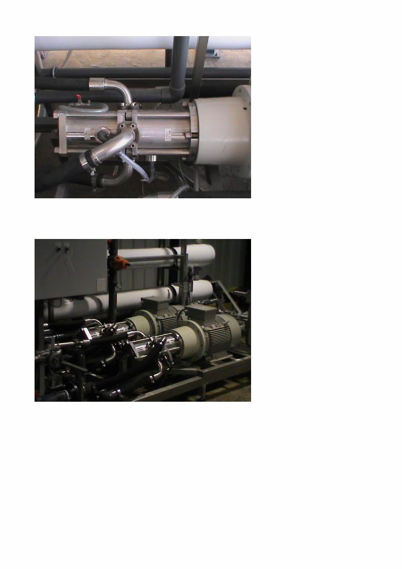

S18
59.8
1/0
1-E
N
SALINNOVA GmbH67240 Bobenheim-Roxheim• Gutenbergstraße29 • (Germany)Fon +49 6239 99391-11 • Fax +49 6239 99391-99www.salinnova.com