Embed Size (px)
Citation preview

SALTRO TPC readout systemPresented by Ulf MjörnmarkLund University
1

Overview of current designThe Front End Multi Chip Module (MCM)Low Voltage (LV) systemDetector Control System (DCS)Serial Readout Unit (SRU) & Trigger & Power PulsingDAQ systemStatus & Time scale
2

DAQTRIGGER
FRONT END
LCTPCENDPLATE
CONTROL
Overview
3
7 pad planemodules
1 18 cmFront End = 25MultiChipModulesconnected ona pad plane

“same” except Low Voltage
Current:FEC = 8 ALTRO + 8 PCA16128 channelsParallel readout bus17*18 cmFPGA board controller
Multi Chip Module (MCM) = 8 SALTRO128 channelsSerial readout2.5*3.5 cmCPLD (firmware Brussels)
Component placementSide view
Multi Chip Module (MCM)
Untested &Unpackaged chipBonded on CarrierTest (unknown yield)!BGA on main boardWith industry
4

Low Voltage Card
5 MCM * 8 Voltages = 40 regulators
MCM1 MCM2 MCM3 MCM4 MCM5
Monitor on each Low Voltage card48 voltages40 currents1 temperature
On each MCM1 temperature1 DAC
Control of individual regulatorOn/off
~700 settings/values per pad plane
DetectorControlSystem
5
5 low voltage cards and

260 W
110 W (regulators)
Detector Control System
Standalone MonitoringAutomatic power off!
Expensive things!Do not want to burn it all
CO2 cooling (Japan)
? cooling
STOP TRIGGER/DAQ/ALARMHow?
Near electronics
In control room
Display/Logging/Control: DOOCS (used at DESY)(Distributed Object Oriented Control System)
6
370 W >>> power pulsing
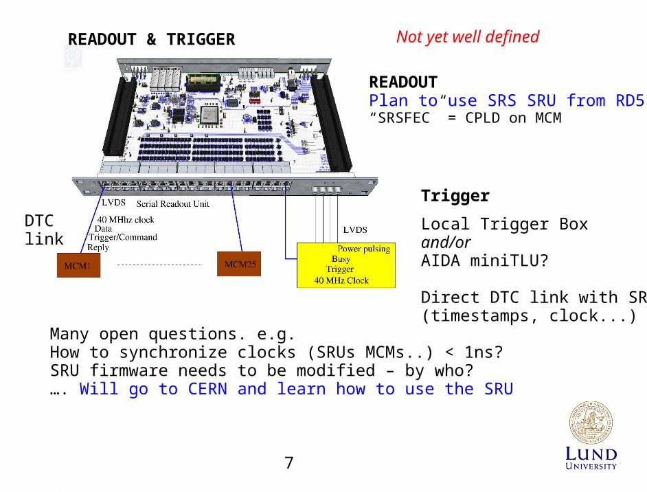
DTC link
Many open questions. e.g.How to synchronize clocks (SRUs MCMs..) < 1ns? SRU firmware needs to be modified – by who?…. Will go to CERN and learn how to use the SRU
READOUTPlan to use SRS SRU from RD51“SRSFEC” = CPLD on MCM
Local Trigger Boxand/orAIDA miniTLU?
Direct DTC link with SRU?(timestamps, clock...)
READOUT & TRIGGER Not yet well defined
7
Trigger

EUDET system:Based on ALICE DATE/DDL/DRORC linkCan it be used for test setup?
DAQ
AIDA system:Plan to use ALICE DATE and 10 Gb ethernet(DDL and 10 Gb ethernet are used in ALICE with SRU)
Common DAQ:EUDETproblem to compile DATE routines with EUDAQ scheleton.
AIDAinstead use a well defined protocol,to be implemented in the user code,and no compilation with a common scheleton is needed.(can one avoid the compilation problem with the “AIDA system”– do not know)
Not yet well defined
8

STATUS
Multi Chip ModuleSALTRO
600 untested naked chips existCarrier board
design readyIndustry collaboration to start to develop bonding/mount techniques
Bigger prototype MCM soon to be produced (with one packaged SALTRO)Firmware started to be developed in Brussels
Low Voltage boardDesign readyPrototype board soon to be produced
Detector Control SystemHardware - design ready, soon producedSoftware – in progress
DAQBought one SRU – will soon go to CERN to learnTrigger/Power pulsing/DAQ hard/software still to be defined and done
TIME SCALE
1 year - test system in beam2 year - final system
9