Embed Size (px)
Citation preview
Combustion characteristics of biodiesel saturated with pyrolysis oil for power generation in gas turbines
Kurji Hac, Valera-Medina A a*, Runyon J a, Giles A a, Pugh D a, Marsh R a
Cerone N b,d, Zimbardi F b, Valerio V b, aCardiff University, Queen’s Building, Cardiff CF24 3AA, United Kingdom*[email protected] b ENEA, Rotondella, Italyc Kerbela University ,College of Engineering , Mechanical Department ,Kerbela, Iraqd Università degli studi di Napoli "Federico II"Abstract
There is a perceived need for multi-fuel burner geometries capable of operating with variable composition fuels
from diverse sources to achieve fuel flexibility in gas turbines. The objective of the research covered herein is a
comparison study between two liquid fuels, a biodiesel (in a pure form) and the biodiesel as a saturated mixture with
a pyrolysis by-product; these two fuels were compared against a standard kerosene as a baseline. The research
methodology involved two stages: firstly atomization patterns and injection regimes were obtained using a high
speed imaging method, secondly a combustion test campaign was undertaken using a swirl burner to quantify the
operational behaviour, species production and exhaust gas compositions of the fuels. Emissions, flame stability
trends and power outputs were measured at gas turbine relevant equivalence ratios. Excess oxygen and atomization
trends in the biodiesel seem to be playing a major role in the production of emissions and flame stability when
compared to kerosene. Also, heavy organics seem to be acting as catalytic substances for OH production close to the
burner mouth. In terms of stability and combustion, it is proposed that the saturated blend would be a viable
candidate for power generation.
Keywords: Atomization, combustion, Gas Turbine, Biodiesel
© 2014ElsevierLtd.Allrightsreserved.
I. INTRODUCTION
Reliable and economically viable alternatives to current fossil fuel products are continually being
sought as pressures from fuel cost, security and environmental impact act on the fuel and energy
industry [1]. In terms of liquid fuels, Diesel is largely utilized in commercial, domestic and
industrial applications for power and heat generation; it is also used as backup fuel in gas
turbines. There has been recent interest in using bio-derived liquid fuels such as biodiesels for
gas turbine operation, but naturally there are concerns as to the operability and reliability of
using less synthetic, more heterogeneous substances for fuels in such high value assets. Biodiesel
products are often highly oxygenated fuels and have been used as an alternative source of fuel
for diesel engines to improve combustion performance. Biodiesel can be considered a more
1
1
23
4
5
6789
1011
12
13
14
15
16
17
18
19
20
21
22
23
24
25
2627
28
29
30
31
32
33
34
35
36
environmentally benign fuel (when compared to fossil-based fuels) in terms of sulphur content,
flash point, aromatic carbon content and biodegradability, provided this fuel could be used in gas
turbines without major modifications [2].
Modern gas turbines will typically operate at lean equivalence ratios, which are between 0.5 and
1.0, depending on operational load and emissions reduction across a range of power outputs.
Biodiesel has demonstrated a reduction of un-burnt hydrocarbons (UHC), carbon monoxide (CO)
and particulate matter (PM) without reducing the power output significantly [3]. Experiments
have shown a reduction of 12% for both CO and PM emissions and 20% for UHC emissions by
co-firing 20% biodiesel in diesel fuel blends. Emissions reduction was about 48% for CO and
PM and 68% for UHC when using 100% biodiesel. However, some research has seen a marginal
increase in NOx (1–6%) [4]. The presence of extra (fuel-bound) oxygen has been shown to result
in overall slightly leaner combustion, which has the resulting benefit of increasing the thermal
efficiency [5]. Emissions such as Polycyclic Aromatic Hydrocarbons (PAH) were also found to
be less prevalent during biodiesel combustion. CO2 emissions aside, biodiesel can be considered
a cleaner fuel than fossil-derived diesel because it has almost no sulphur content (typically less
than 15 ppm), no aromatics, and contains about 10% oxygen, which can improve the overall
combustion process. Biodiesel also has a comparatively high lubricity and can hence be used as a
lubricating agent for traditional diesel blends [1].
Work in the area of biofuels testing has often shown promising results where emissions are
comparable to control studies using fossil-based Diesel [6]. Panchasara et al. [7] studied the
combustion performance of pure biodiesel against diesel–vegetable oil blends in a simulated gas
turbine combustor. These experiments were performed at atmospheric pressure with air-assisted
injector/atomisers in swirling flows. The results showed that fuel chemistry effects were minimal
since combustion emissions for a given fuel were largely dependent on the atomisation process.
Campbell et al. [8] studied alternative fuels that had been deemed suitable for gas turbines
focussing on vegetable oils. They highlighted several properties of vegetable oils that would
require special consideration such as transportation, storage, delivery and injection into industrial
gas turbines. Hashimoto et al. [9] compared the emissions of palm derived biodiesel with those
of fossil derived diesel in a gas turbine burner. The result indicated that NOX emissions for palm
biodiesel were consistently lower compared to those of diesel as a function of excess air ratio,
average droplet diameter, atomizing air pressure and viscosity. These results indicate that
2
37
38
39
40
41
42
43
44
45
46
47
48
49
50
51
52
53
54
55
56
57
58
59
60
61
62
63
64
65
66
67
biodiesel has the potential to produce lower NOX emissions than diesel under gas turbine
conditions, contrary to the higher NOX emissions measured in reciprocating compression-ignition
engine experiments [10].
Biodiesel and diesel have notable differences in physical properties, and it is therefore necessary
to study the spray characteristics of biodiesel in relation to its application in internal combustion
engines and gas turbines - more so given that atomization behaviour has a significant effect on
emissions. Senatore et al. [11] analysed results of an experimental study fuelling a common-rail
diesel engine with 100% rapeseed biofuel, comparing their findings with a blend of rapeseed and
Used Fried Oil (UFO), showing good correlation between fuels. Zhao et al. [12] observed that
the spray penetration and spray cone angle of biodiesel were larger than those of diesel.
Similarly, Lee et al. [13] examined the atomization characteristics of biodiesel-blended fuels
using a spray visualization system and phase Doppler particle analyser. They deduced that the
biodiesel blended fuels had comparable spray tip penetrations to conventional diesel but higher
Sauter Mean Diameter because the viscosity and surface tension of the biodiesel were higher
than the conventional diesel fuel. Being a crucial topic for the improvement in burnout and a key
factor in emissions, advanced laser-based spray quantification techniques have been used and
developed to understand atomization patterns for diesel and biodiesel [14, 15].
The biodiesel used in the work in this paper is a by-product from a biomass gasification process;
specifically a liquid condensate from the product gas cleaning process. This is a crucial stage in
the thermal conversion of biomass, especially where the main product gas components CO and
H2, are used for Fischer–Tropsch synthesis or as high purity fuel [16]. Biodiesel is widely used
for scrubbing the raw syngas as it efficiently removes the condensable (heavier) hydrocarbons
produced from biomass pyrolysis. Experimental investigations have been carried out on similar
post-scrubbing liquids where combustion of blends of pyrolytic oil, biodiesel or ethanol in
engines and boilers [17, 18] have proved the suitability of the approach. This has included large-
scale applications and highlighted a need to standardize the trade of this product [19]. Cappelletti
et al. redesigned a micro gas turbine to permit stable combustion of pyrolysis oil showing that
the combustion is only stable in the combustor’s secondary zone [20]. However, further works
concerning the use of pyrolysis oil as fuel for gas turbines are scarce at the time of writing.
3
68
69
70
71
72
73
74
75
76
77
78
79
80
81
82
83
84
85
86
87
88
89
90
91
92
93
94
95
96

The research questions to be addressed include measurement of the physical properties,
atomization behaviour, combustion characteristics, and emissions of the new biodiesel blend and
how this compares with a standard kerosene. Therefore, the aim of this study is to demonstrate
the potential of this saturated biodiesel for power generation as a backup fuel for Integrated
Gasification Combined Cycles (IGCC) and compare its combustion behaviour with kerosene and
unsaturated biodiesel. Atomization patterns and injection regimes were obtained using high-
speed imaging. Calorific values, density, and surface tension were measured and proximate
analyses were performed to act as a comparison between the fuels. Knowing the properties and
atomization behaviour, these fuels were fired into a generic swirl burner capable of simulating
real gas turbine conditions. Exhaust gas emissions, OH* chemiluminescence and combustion
stability were measured at similar flow rates, providing evidence of the potential for and
constraints to using this saturated biodiesel as an alternative fuel for gas turbines.
II. Experimental Setup
A. Characterisation
Experiments were conducted at Cardiff University, UK, and ENEA, Italy. The surface tension
and density were experimentally obtained using a temperature controlled LAUDA TVT 1 Drop
Volume Tensiometer. The viscosity was experimentally obtained using a U–Tube Viscometer.
The Higher Heating Value (HHV) was determined by a Parr 6100 calorimeter bomb and an
IKCA C4000 calorimeter using benzoic acid as reference. An ultimate analysis was carried out
by using an elemental analyzer, a Perkin Elmer CHN/O according to UNI EN 15104. Ash was
analyzed to determine the elemental content according to the methods CEN 343 or CEN 345 by
using an ICP-OES Agilent 720ES. Oxygen was calculated by difference of species. Gas
Chromatography (GC) was employed by using an Agilent HP 6890 GC.
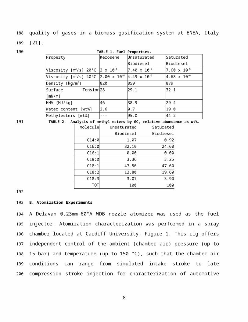
Three test fuels were used in the experimental campaign, including unsaturated and saturated
biodiesels, and kerosene. Their properties are given in Table 1, with the GC analysis of the
methyl esters in Table 2. The unsaturated biodiesel is derived from cooking oil, giving a
composition similar to that obtained for methyl ester. The fraction of biodiesel that is included in
the saturated sample has almost the same elemental composition (C 76.28%, H 12.55%, O 11.04
%) as that of the unsaturated biodiesel. However, since the biodiesel has been used to clean up
the gas stream from a gasification process, the saturated biodiesel represents less than half of the
4
97
98
99
100
101
102
103
104
105
106
107
108
109
110
111
112
113
114
115
116
117
118
119
120
121
122
123
124
125
126
total mass of the final sample. Besides water, the remaining 36.8% is a complex mix of organic
molecules including formic acid (molecular mass 46 g/mol) and aromatic compounds (molecular
mass 200 g/mol). This scrubbing process has been carried out to improve the quality of gases in a
biomass gasification system at ENEA, Italy [21].TABLE 1. Fuel Properties.
Property Kerosene Unsaturated Biodiesel Saturated BiodieselViscosity [m2/s] 20°C 3 x 10⁻⁶ 7.40 x 10⁻⁶ 7.60 x 10⁻⁶
Viscosity [m2/s] 40°C 2.00 x 10⁻⁶ 4.49 x 10⁻⁶ 4.68 x 10⁻⁶
Density [kg/m3] 820 859 879Surface Tension [mN/m] 28 29.1 32.1HHV [MJ/kg] 46 38.9 29.4Water content [wt%] 2.6 0.7 19.0Methylesters [wt%] --- 95.0 44.2
TABLE 2. Analysis of methyl esters by GC, relative abundance as wt%.Molecule Unsaturated Biodiesel Saturated Biodiesel
C14:0 1.07 0.92C16:0 32.10 24.60C16:1 0.00 0.00C18:0 3.36 3.25C18:1 47.50 47.60C18:2 12.80 19.60C18:3 3.07 3.90TOT 100 100
B. Atomization Experiments
A Delavan 0.23mm-60°A WDB nozzle atomizer was used as the fuel injector. Atomization
characterization was performed in a spray chamber located at Cardiff University, Figure 1. This
rig offers independent control of the ambient (chamber air) pressure (up to 15 bar) and
temperature (up to 150 °C), such that the chamber air conditions can range from simulated intake
stroke to late compression stroke injection for characterization of automotive applications.
Reading uncertainty of the pressure gauges was ±0.5 bar.
5
127
128
129
130
131
132
133
134
135
136
137
138
139
140
FIG 1. Spray rig and imaging setup diagram.
High-speed imaging was used to detail the atomization parameters, namely spray angle. The
spray angle was defined as the angle formed by the cone of liquid leaving the nozzle orifice
where two straight lines were wrapped with the greatest outer side of the spray [22]. A Photron
Fastcam APX-RS high-speed camera operating at 1000 frames/s was also used with a 105 mm,
1:2.8 Nikon lens. A 50W straight projector bulb was used as a light source, accessing the
chamber through one of its 3 quartz windows and placed at a 90° angle to the high-speed camera.
The atomizer nozzle was placed in the top of the experimental test rig to spray the fuel at
operating pressures from 8 to 26 bar absolute, collecting the bulk volume of the spray at the
bottom of the rig. The injector pressure was adjusted within the range of 8-26 bar using
compressed nitrogen, passing into a liquid accumulator as shown in Figure 1. The resulting
images were analysed using Photron FASTCAM PFV ver 2.4.1.1 software and MATLAB
R2013a.
C. Gas Turbine Burner Trials
Experiments were performed at the Gas Turbine Research Centre (GTRC), which is a Cardiff
University facility located at Port Talbot [23]. The rig used herein was the High Pressure Optical
Chamber (HPOC), capable of delivering 5 kg/s of air at 900K and 16 bar absolute, thus allowing
combustors to be operated at conditions applicable to use in a power generation derivative gas
turbine engine. Coriolis mass flow meters were used to achieve precise measurement of
6
141142
143
144
145
146
147
148
149
150
151
152
153
154
155
156
157
158
159
160

flowrates with an accuracy of ±0.5% RD plus ±0.1% FS. In this particular research, the HPOC
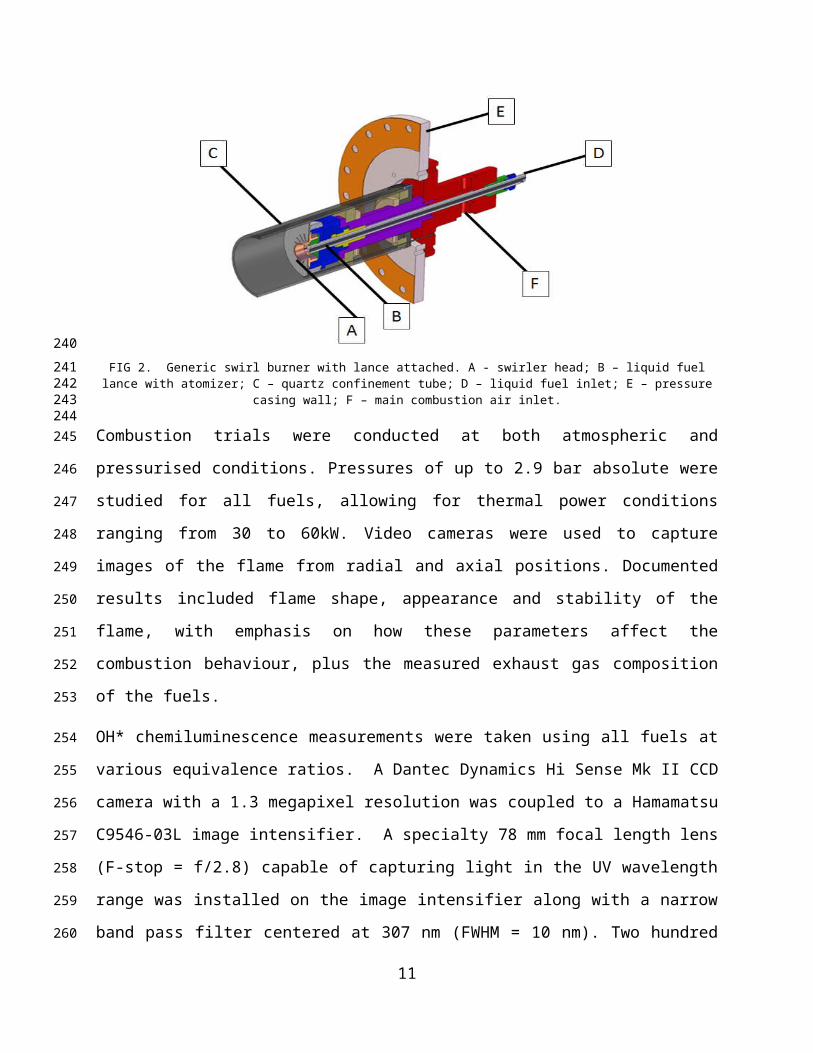
rig was fitted with a generic pre-mixed swirl burner, Figure 2. The generic swirl burner consists
of a main body that receives both the premixed (gaseous) fuel and oxidizer plus a central lance
that is used for liquid injection. The burner body includes a premixing chamber where most of
the gas premixing takes place upstream of the swirl chamber. Finally, the burner is confined by
a quartz tube fitted to the system to simulate the appropriate expansion ratio from the burner into
the engine’s combustion chamber; in this case an expansion ratio of 4 was used.
FIG 2. Generic swirl burner with lance attached. A - swirler head; B – liquid fuel lance with atomizer; C – quartz confinement tube; D – liquid fuel inlet; E – pressure casing wall; F – main combustion air inlet.
Combustion trials were conducted at both atmospheric and pressurised conditions. Pressures of
up to 2.9 bar absolute were studied for all fuels, allowing for thermal power conditions ranging
from 30 to 60kW. Video cameras were used to capture images of the flame from radial and axial
positions. Documented results included flame shape, appearance and stability of the flame, with
emphasis on how these parameters affect the combustion behaviour, plus the measured exhaust
gas composition of the fuels.
OH* chemiluminescence measurements were taken using all fuels at various equivalence ratios.
A Dantec Dynamics Hi Sense Mk II CCD camera with a 1.3 megapixel resolution was coupled
to a Hamamatsu C9546-03L image intensifier. A specialty 78 mm focal length lens (F-stop =
f/2.8) capable of capturing light in the UV wavelength range was installed on the image
intensifier along with a narrow band pass filter centered at 307 nm (FWHM = 10 nm). Two
hundred images were taken at 10 Hz at each test condition using Dantec’s DynamicStudio
software, while the image intensifier gain was selected via remote control. All images were
7
161
162
163
164
165
166
167
168169170171172
173
174
175
176
177
178
179
180
181
182
183
184
taken through the top window of the HPOC at a 90° angle to the direction of flow. Abel
inversion of the resulting time-averaged images was used to provide better recognition of the
OH* distribution across the flame [24, 25]. Abel inversion was performed on the temporal
average of 200 images taken at 10 Hz (20 seconds of run time), and then used the resulting
image intensity values in the normalization process.
FIG 3. Schematic diagram of the HPOC showing (a) liquid fuel lance, (b) inlet plenum, (c) HPOC outer casing, (d) air plenum,
(e) radial-tangential swirler insert, (f) exit nozzle, (g) quartz window for OH* visualization, and (h) quartz confinement. Flow
goes from left to right.
Two pieces of equipment were used to characterise combustion emissions. An integrated system
developed by Signal Instruments comprising several analysers: a Flame Ionisation Detector
(FID), employed within a Signal 3000HM analyser to detect total hydrocarbons (THCs),
calibrated with propane in the range 0-890 ppmV. A heated vacuum chemiluminescense analyser
(Signal 4000VM), simultaneously employed to quantify NOx concentrations, calibrated to full
scale of 37.1 ppmV NO and 1.9 ppmV NO2. The system also contains a multi-gas analyser
(Signal MGA) containing an infrared cell for measurement of CO (calibrated for 0-900 ppmV)
and CO2 (0-9%V), in addition to a paramagnetic O2 sensor (up to 22.5%V). A standalone
Rosemount NGA 2000 multi-gas analyser provided secondary readings of CO, CO2 and O2 all
calibrated to the same concentrations previously stated. Relative accuracy of these gas analysis
methods after calibration shows a ±5% reading error.
Combustion equilibrium analyses were carried out utilizing GASEQ [26] under stoichiometric
conditions in order to provide a better understanding of the evolution of some of the species that
participate in the process and the final flue gas concentrations. The methyl-formate reaction
mechanism developed by Fisher et al. [27] has been used as a surrogate for biodiesel. Methyl-
formate was chosen as a surrogate molecule in order to obtain a reaction close to the one
8
185
186
187
188
189
190191192193
194
195
196
197
198
199
200
201
202
203
204
205
206
207
208
209

expected from biodiesel. Although methyl-formate mechanisms have shown differences to
biodiesel [27], the results provide the basis for the discussion on exhaust gas composition.
III. Results – (a) Spray Characterisation
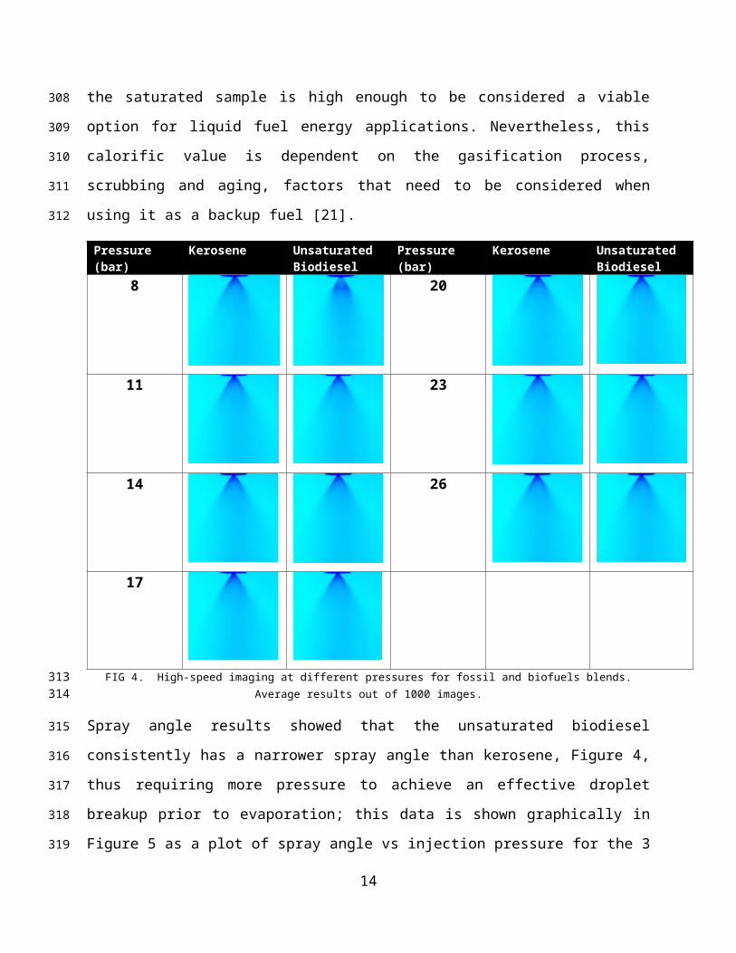
Characterisation studies (Table 1) showed that the calorific value for the saturated biodiesel is
lower than that of kerosene and the unsaturated biodiesel. Although this was expected, it is still a
promising result which shows that the energy content of the saturated sample is high enough to
be considered a viable option for liquid fuel energy applications. Nevertheless, this calorific
value is dependent on the gasification process, scrubbing and aging, factors that need to be
considered when using it as a backup fuel [21].
Pressure (bar) Kerosene Unsaturated Biodiesel
Pressure (bar) Kerosene Unsaturated Biodiesel
8 20
11 23
14 26
17
FIG 4. High-speed imaging at different pressures for fossil and biofuels blends. Average results out of 1000 images.
Spray angle results showed that the unsaturated biodiesel consistently has a narrower spray angle
than kerosene, Figure 4, thus requiring more pressure to achieve an effective droplet breakup
prior to evaporation; this data is shown graphically in Figure 5 as a plot of spray angle vs
9
210
211
212213214
215
216
217
218
219
220
221
222
223

injection pressure for the 3 fuels tested as studied by others [7, 28]. Similar results were obtained
for the saturated biodiesel, Figure 5, which showed a smaller spray angle linked to the presence
of solid matter (from the particulate matter contaminants present in the saturated fuel) and
resultant greater viscosity. Narrower spray angles are a known issue for higher viscosity biofuels
which can result in combustion problems such as high smoke emission. Spray angle is also
known to be a function of the ratio between the ambient density and the sprayed fluid density,
hence the results in Figure 5 are logical given the properties discussed herein. The likely
outcome for attempts to burn this fuel under similar conditions as a fossil fuel is that there may
be no combustion if the pressure used in the fuel line is not high enough to produce a well-
atomized spray. Suggested solutions to this issue include biofuel preheating to provide lower
viscosity and hence improve atomisation, along with higher injection pressures to be used for
spraying the saturated biodiesel.
4040
45
60
7055
57
59
61
63
65
67
69
71
73
75
5 10 15 20 25 30
Spra
y Co
ne A
ngle
[deg
rees
]
Injection Pressure [bar]
Kerosene
Unsaturated Biodiesel
Saturated Biodiesel
FIG 5. Effect of fuel injection pressure on spray angle
III. Results – (b) Combustion behaviour in the HPOC
Flame appearance
For kerosene, the flame was stable and sufficiently radiative to show the production of soot that
would be expected with the lack of oxygen for complete burnout under rich conditions. Under
comparable air to fuel ratios, the unsaturated biodiesel showed a visibly lower quantity of
exhaust soot, presumably due to the larger quantity of oxygen bound into the fuel. The saturated
biodiesel also burnt with a stable flame, but it was evident that the amount of soot coming from
the saturated biodiesel was the highest of all the fuels tested, as shown in Figure 6 and expected
from previous literature [29]. Soot formation was so high that the quartz confinement tube was
10
224
225
226
227
228
229
230
231
232
233
234
235
236237
238
239
240
241
242
243
244
245
246
stained with black soot deposits after only a few seconds of operation under rich (ϕ ~ 1.2)
conditions. This behaviour also correlated with the considerable THC emissions (shown later) as
a consequence of its saturated constituents. Also, there was visible evidence that the atomization
of the fuel was incomplete, with the appearance of several glowing (presumably fuel-rich)
projections in the flame. This correlated with the spray visualisation experiments, which showed
that the saturated biodiesel formed into small droplets at a noticeably slower rate than the other
fuels. The ensuing larger spray droplets require more time to evaporate and hence thermal
decomposition of the hydrocarbons will be impeded, resulting in incomplete burnout, hence the
observed soot.
A. B. C.FIG 6. Visible flame at equivalence ratios 0.6. A) Saturated biodiesel, high soot glowing. B) Unsaturated biodiesel, and C)
Kerosene.
It can be said that overall the saturated biodiesel blend under lean conditions (i.e. ϕ < 1) behaved
favourably in terms of flame stability and burning processes compared to the other fuels tested.
As the subsequent gas analysis will show, if the flame can be stabilised at low equivalence ratios,
the CO formation will be lower with more CO2 produced, thus reflecting a higher measured
combustion efficiency. Total unburned hydrocarbons will be lower although NOX will increase
as a consequence of the additional (fuel bound) nitrogen and comparably higher temperatures
than the other fuels tested. Nevertheless, if equivalence ratios of ~0.55 are attained, then
measured outlet concentrations of NOx will be in the same order of magnitude to those observed
in kerosene flames.
Exhaust gas analysis
11
247
248
249
250
251
252
253
254
255
256
257
258259
260
261
262
263
264
265
266
267
268
269270

Figure 7 shows THC emissions as a function of equivalence ratio for the kerosene and biofuels
tested under atmospheric conditions. A log scale has been used since the THC emission above
stoichiometry was orders of magnitude higher than the values measured below. It can be seen
that the saturated biodiesel mostly produced higher concentrations of unburnt hydrocarbon
products, especially at higher equivalence ratios, which corresponds to the physical observations
in the preceding section. There was some evidence to suggest that increasing the HPOC pressure
had reduced net THC emissions, but more data would be required to verify this. Kerosene did not
show any measurable concentrations of THC in the exhaust, demonstrating complete burnout of
the fuel under the conditions studied. This correlates well with the spray results given that the
kerosene spray was noticeably more atomized [30].
FIG 7. THC exhaust gas concentration (dry) as a function of equivalence ratio for kerosene and the two biofuels at atmospheric
pressure.
Figure 8 shows O2 concentration as a function of equivalence ratio under atmospheric conditions.
This value is based on the measured fuel and air flow rates through the burner, and the gas
analysis. The measurement of oxygen and CO allowed for the identification of the near
stoichiometric operating point. Different trends can be seen between all fuels, with the
unsaturated blend showing the highest O2 concentrations due to the presence of oxygen in the
bio-blend. However, the saturated biodiesel showed the lowest trend, which has been attributed
to the presence of solid carbon-based particles in the liquid fuel; hence more oxygen being
required per unit mass of fuel burn due to a much greater average carbon composition [1, 31].
12
271
272
273
274
275
276
277
278
279
280
281282283
284
285
286
287
288
289
290
291
FIG 8. O2 exhaust gas concentration (dry) as a function of equivalence ratio for kerosene and the two biofuels at atmospheric
pressure.
Figure 9 shows CO2 emissions as a function of equivalence ratio for the kerosene and biofuels
tested under atmospheric conditions. There is a difference in the behaviour of the biofuels in
comparison to the kerosene, demonstrated by the peak CO2 values at higher concentrations for
the bio-blends. It is apparent that the biofuels produced marginally more CO2 than the kerosene
under identical air flow rates, which is likely given the higher carbon to hydrogen ratio in the
heavier fuels [5]. As expected, there is greater exhaust CO2 concentration from the saturated fuel
as a consequence of further reactions of the solid particles; at higher pressures this was also the
case. It should be noted that these differences are comparatively very small, so under these
circumstances the results can be considered to be within the experimental uncertainty of the
measurement.
FIG 9. CO2 exhaust gas concentration (dry) as a function of equivalence ratio for kerosene and the two biofuels at atmospheric
13
292293294
295
296
297
298
299
300
301
302
303
304
305306
pressure.
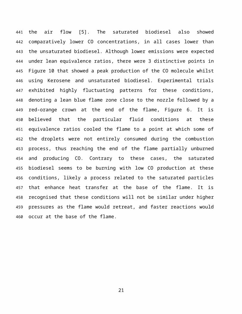
Figure 10 shows CO emissions as a function of equivalence ratio for the kerosene and biofuels
tested under atmospheric conditions; the production of CO is due to incomplete combustion. At
atmospheric and elevated pressure, results showed that CO emissions generally decreased with
the biodiesels, most likely as a consequence of the fuel-bound oxygen in the molecule which
starts reacting further downstream than the oxygen contained in the air flow [5]. The saturated
biodiesel also showed comparatively lower CO concentrations, in all cases lower than the
unsaturated biodiesel. Although lower emissions were expected under lean equivalence ratios,
there were 3 distinctive points in Figure 10 that showed a peak production of the CO molecule
whilst using Kerosene and unsaturated biodiesel. Experimental trials exhibited highly fluctuating
patterns for these conditions, denoting a lean blue flame zone close to the nozzle followed by a
red-orange crown at the end of the flame, Figure 6. It is believed that the particular fluid
conditions at these equivalence ratios cooled the flame to a point at which some of the droplets
were not entirely consumed during the combustion process, thus reaching the end of the flame
partially unburned and producing CO. Contrary to these cases, the saturated biodiesel seems to
be burning with low CO production at these conditions, likely a process related to the saturated
particles that enhance heat transfer at the base of the flame. It is recognised that these conditions
will not be similar under higher pressures as the flame would retreat, and faster reactions would
occur at the base of the flame.
FIG 10. CO exhaust gas concentration (dry) as a function of equivalence ratio for kerosene and the two biofuels at atmospheric
pressure.
14
307
308
309
310
311
312
313
314
315
316
317
318
319
320
321
322
323
324
325
326327328
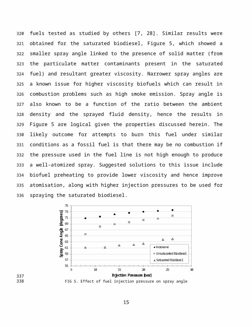
Figure 11 shows NOX emissions as a function of equivalence ratio for the kerosene and biofuels
tested under atmospheric conditions. The results denote that NOX emissions augment with
increasing equivalence ratio towards stoichiometric conditions. The saturated and unsaturated
biodiesels produced higher NOX emissions than kerosene at all pressures. It is believed that
higher NOX emissions from the biodiesels were related to a greater CH formation, leading to
prompt NOX via CH+N→HCN reactions as observed by others [33] and discussed later herein.
Moreover, the higher temperature of the reaction produced by the excess oxygen and improved
combustion in the saturated biodiesel could also lead to higher Zeldovich emissions (thermal
NOX). Contrary to the experimental results, atomization behaviour was thought to be a parameter
that would control the resultant NOX concentrations for the bio-blends, as decreased spray angle
and bigger droplet size [34] would result in the fuel remaining unburned for longer periods of
time and greater axial distances, reducing NOX by a decrease in the combustion efficiency,
burning further downstream to complete the reaction.
When compared with the saturated blend, both kerosene and the unsaturated biodiesel produce
lower NOX emissions, a phenomenon that could be linked to the content of nitrogen in the
organic matter carried by the saturated blend [29]. The presence of solid particles also shows
traces of a more efficient combustion regime, i.e. lower CO and higher CO2, thus higher
temperatures and increased Zeldovich NOX. When considering the effect of pressure on NOX
concentration, it was also observed that NOX emissions are considerably reduced at higher
pressures, with a peak of 120 ppm under atmospheric conditions, reducing to 25ppm at 2.9 bar
for the saturated biofuel blend. Since the power conditions for all cases are similar at 40 kW, it is
believed that the high pressure forces the flame to retract towards the burner, compacting it and
improving combustion and reactivity.
15
329
330
331
332
333
334
335
336
337
338
339
340
341
342
343
344
345
346
347
348
349
350
351
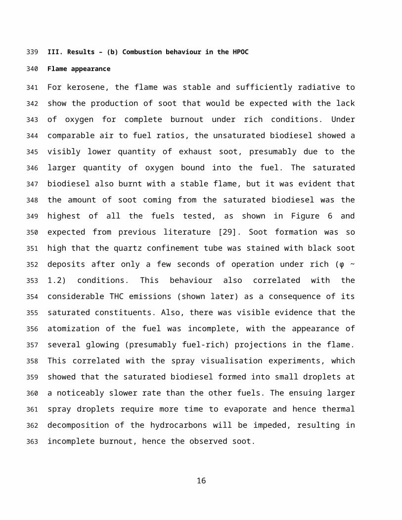
FIG 11. NOx exhaust gas concentration (dry) as a function of equivalence ratio for kerosene and the two biofuels at atmospheric
pressure.
Chemical equilibrium calculations
The measured gas compositions were correlated with chemical equilibrium calculations using
GASEQ, Table 3. Pressures used for the analysis were 1, 10 and 100 bar in order to clearly show
progression of species with increment of pressure. Methyl-formate (C2H4O2) was used as a
surrogate molecule related to larger methyl esters [21, 35]. From the results, the OH radical has
decreased at higher pressures. The greatest changes were observed in the evolution of hydrogen
and oxygen towards the formation of complete combustion molecules such as CO2 and H2O. NO
shows an acute decrease at higher pressures. Although temperatures are higher, lack of oxygen in
the blend limits the production of NO. Moreover, it is believed that OH radical formation is
inhibited by pressure, as discussed in the following section.
TABLE 3. GASEQ equilibrium analyses. Molar fraction and adiabatic temperature of the flame. Molecules Pressure 1 bar Pressure 10 bar Pressure 100 bar
N2 0.64381 0.64698 0.64927H2O 0.16593 0.16904 0.17109CO2 0.15452 0.16165 0.16674CO 0.01704 0.01071 0.00617O2 0.00779 0.00456 0.00239OH 0.00416 0.00256 0.00142H 0.000481 0.000159 0.0000459O 0.000372 0.000127 0.0000365H2 0.00332 0.00196 0.00109NO 0.00258 0.00223 0.00176
Adiabatic Flame Temp 2272K 2331.6K 2372.4K
16
352353354
355
356
357
358
359
360
361
362
363
364
365
366
OH* Chemiluminescence Analyses
OH* chemiluminescence studies were carried out for all conditions. Comparisons between
biofuels were performed to observe the progression of OH radicals at different pressures, Figures
12 and 13. Abel inversion was applied to produce intensity maps normalized on the basis of the
most intense luminosity value. Hence, of all the images shown herein, the highest pixel level is
used to set a nominal maximum luminosity and all of the results are scaled with respect to this,
which allows for a more realistic comparison of global intensity. Results clearly show a large
amount of OH radicals at low pressure in the region where the swirling flame is positioned.
FIG 12. Abel inversion for OH* chemiluminescense for the Unsaturated biodiesel E.R. 0.550 at a) 1.9 bar; and b) 2.9 bar. The
burner outlet is denoted as the grey rectangle at the bottom of the figure.
Considerable variation between blends was observed at high pressure, as shown in Figures 12b
and 13b. The unsaturated biodiesel has decreased its OH* production, reducing the reaction zone
length of this radical and thus chemiluminescence intensity, a phenomenon caused by the
retraction of the flame and greater density as a consequence of increased downstream pressure.
However, the saturated blend kept showing OH* intensity profiles similar to those observed at
lower pressure, as shown in Figure 13. Some conclusions can be drawn from these results; it
seems as if oxygen from the biodiesel was reacting faster than oxygen from air when solid matter
was present in the fuel.
17
367
368
369
370
371
372
373
374
375
376
377
378
379380
381
382
383
384
385
386
387
388
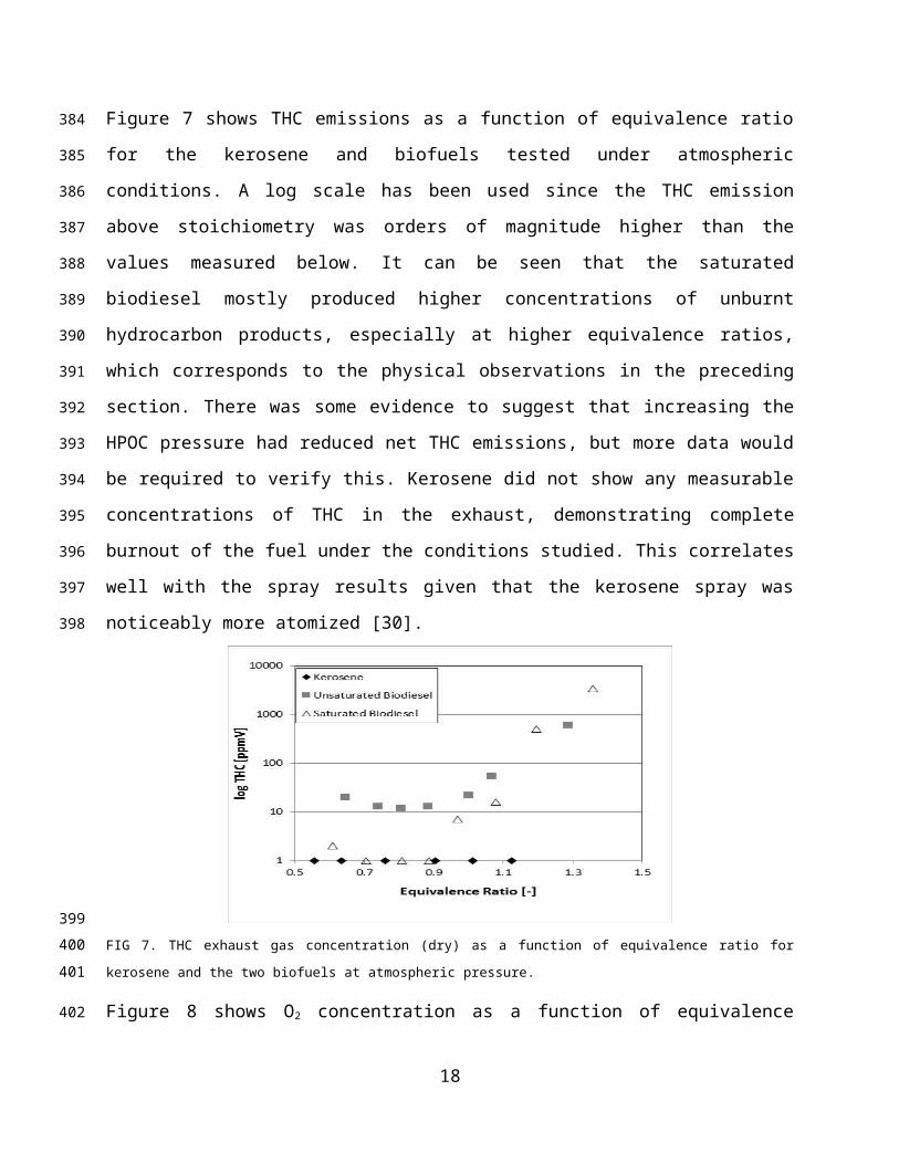
FIG 13. Abel inversion for OH* chemiluminescense Saturated blend E.R. 0.581 at a) 1.9 bar; and b) 2.9 bar.
This assertion comes from the changes in OH* intensity in the unsaturated biofuel at various
pressures. Higher pressures mean greater densities, thus more air adjoining the flame leading to
greater OH* dilution of a process driven by the surrounding atmosphere. However, since the
OH* intensity in the saturated flame is similar at various pressures, it is evident that the OH*
production has been kept almost constant from a source independent of downstream conditions,
i.e. pressure, with minor dilution impacts at the OH* release location.
Further comparison was performed between the different fuels at the same pressure, Figures 14
and 15. The unsaturated blend shows considerable increase in the OH* projections to those
observed in the saturated biodiesel. These differences emphasize the evolution of other species
overtaking OH* production in the saturated blend further downstream of the burner nozzle. From
other works [33] it can be deduced that CH production has been enhanced for the saturated blend
which shows the greatest NOx formation.
FIG 14. Abel inversion for OH* chemiluminescense at same pressure (1.9 bar) and stoichiometry (~0.58). a) Unsaturated blend;
b) Saturated blend.
18
389
390
391
392
393
394
395
396
397
398
399
400
401
402
403404405
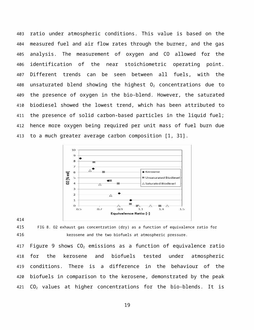
FIG 15. Abel inversion for OH* chemiluminescense at same pressure (2.9 bar) and stoichiometry (~0.59). a) Unsaturated blend;
b) Saturated blend.
Therefore, it can be concluded that solid matter in the fuel also acts as a catalytic substance for
the production of other radicals. Although the particles keep forming CH radicals downstream of
the flame zone that enhance NOx formation, at low equivalence ratios the use of these catalytic
particles also enhances fuel-bound oxygen reactions that remain almost unaltered at higher
pressure. These properties could contribute to the improvement of combustion systems, thus
leading to a good fuel candidate at lean conditions.
Unfortunately, visual observations showed that saturates will tend to produce higher soot
emission at the present concentrations, reducing the applicability of this particular fuel for gas
turbines. However, if the appropriate amount of particles in the bio-fuel to considerably diminish
impacts on materials and components could be met, these particles could be a feasible
mechanism to enhance gas turbine combustion at low cost.
IV. Conclusions
Three fuels, kerosene and a biofuel in unsaturated and saturated form, were tested to compare the
relative performance of the saturated biodiesel for gas turbine applications. It was observed that
injection patterns are less likely to provide effective droplet breakup and atomization due to
higher viscosity and surface tension in the saturated biodiesel. Results indicated that use of the
saturated blend will result in higher NOX concentrations in the exhaust with less oxygen and CO
emissions. Moreover, the saturated solid organic compounds appear to have a catalytic effect to
increase radical production downstream of the flame zone, thus increasing prompt NOX
19
406
407408
409
410
411
412
413
414
415
416
417
418
419
420
421
422
423
424
425
426
427
428

formation. These compounds also appear to be enhancing the production of OH radicals through
reactions with the oxygen embedded in the fuel, thus increasing temperature even further with an
associated production of nitrogen oxides. As a consequence, the increase of operating pressure
had the effect of increasing combustion efficiency. It has been shown that the ideal operability
region for the saturated biodiesel is at very lean conditions, and that under these conditions its
measured exhaust gas concentrations are comparable with the unsaturated biodiesel fuel.
However, visual observations showed that saturates at these concentrations will tend to produce
higher soot emission, reducing the applicability of the fuel for gas turbines.
Acknowledgements
The authors gratefully acknowledge the support from the Biofuels Research Infrastructure for
Sharing Knowledge (BRISK) 7th Framework Programme to conduct this project (ref. CFU1-28-
07-13). Hayder Kurji also thanks the Iraqi government for the support of his studies through a
PhD scholarship. The authors thank Steve Morris, Terry Treherne and Jack Thomas for their
invaluable contributions.
V. References
[1] Basha, S. A., Gopal, K. R., and Jebaraj, S., 2009, "A review on biodiesel production, combustion, emissions and performance," Renewable and Sustainable Energy Reviews, 13(6-7), pp. 1628-1634.[2] Demirbas, A., 2007, "Progress and recent trends in biofuels," Progress in Energy and Combustion Science, 33(1), pp. 1-18.[3] Nascimento, M. A. R., Lora, E. S., Corrêa, P. S. P., Andrade, R. V., Rendon, M. A., Venturini, O. J., and Ramirez, G. A. S., 2008, "Biodiesel fuel in diesel micro-turbine engines: Modelling and experimental evaluation," Energy, 33(2), pp. 233-240.[4] Gupta, K. K., Rehman, A., and Sarviya, R. M., 2010, "Evaluation of soya bio-diesel as a gas turbine fuel," Iranica Journal of Energy & Environment, 1(3), pp. 205-210.[5] Habib, Z., Parthasarathy, R., and Gollahalli, S., 2010, "Performance and emission characteristics of biofuel in a small-scale gas turbine engine," Applied Energy, 87(5), pp. 1701-1709.[6] Pereira, C., Wang, G., and Costa, M., 2014, "Combustion of biodiesel in a large-scale laboratory furnace," Energy, 74, pp. 950-955.[7] Panchasara, H. V., Simmons, B. M., Agrawal, A. K., Spear, S. K., and Daly, D. T., 2009, "Combustion Performance of Biodiesel and Diesel-Vegetable Oil Blends in a Simulated Gas Turbine Burner," Journal of Engineering for Gas Turbines and Power, 131(3), p. 031503.[8] Campbell, A., Goldmeer, J., Healy, T., Washam, R., Moliere, M., and Citeno, J., 2008, "Heavy duty gas turbines fuel flexibility," Proceedings of ASME Turbo Expo GT2008-51368.[9] Hashimoto, N., Ozawa, Y., Mori, N., Yuri, I., and Hisamatsu, T., 2008, "Fundamental combustion characteristics of palm methyl ester (PME) as alternative fuel for gas turbines," Fuel, 87(15-16), pp. 3373-3378.
20
429
430
431
432
433
434
435
436
437
438
439
440
441
442
443
444445446447448449450451452453454455456457458459460461462463464465466
[10] Canakci, M., 2007, "Combustion characteristics of a turbocharged DI compression ignition engine fueled with petroleum diesel fuels and biodiesel," Bioresour Technol, 98(6), pp. 1167-1175.[11] Senatore, A. C. M., Allocca, L., Vitolo, S., and Rocco, V. , 2005, "Experimental characterization of a common rail engine fuelled with different biodiesel," SAE Paper, 2005-01-2207.[12] Zhao, X.W., H. X. K., He C., Tan J.W., 2008, "Experimental study on spray characteristics of biodiesel oil," Chin Intern Combust Engine Eng, 1:16–9.[13] Lee, C.S., P. S. W., Kwon, S.I. , 2005, "An experimental study on the atomization and combustion characteristics of biodiesel-blended fuels," Energy Fuels, 19, pp. 2201–2208.[14] Grimaldi, C., P. L., 2000, "Experimental comparison between conventional and bio derived fuels sprays from a common rail injection system," SAE Paper, 2000-01-1252.[15] Desantes, J. M., Payri, R., Salvador, F. J., and Soare, V., 2005, "Study of the influence of geometrical and injection parameters on diesel sprays characteristics in isothermal conditions," SAE Paper, 2005-01-0913.[16] Bocci, E., Di Carlo, A., McPhail, S. J., Gallucci, K., Foscolo, P. U., Moneti, M., Villarini, M., and Carlini, M., 2014, "Biomass to fuel cells state of the art: A review of the most innovative technology solutions," International Journal of Hydrogen Energy, 39(36), pp. 21876-21895.[17] Prakash, R., Singh, R. K., and Murugan, S., 2013, "Experimental investigation on a diesel engine fueled with bio-oil derived from waste wood–biodiesel emulsions," Energy, 55, pp. 610-618.[18] Martin, J. A., and Boateng, A. A., 2014, "Combustion performance of pyrolysis oil/ethanol blends in a residential-scale oil-fired boiler," Fuel, 133, pp. 34-44.[19] Lehto, J., Oasmaa, A., Solantausta, Y., Kytö, M., and Chiaramonti, D., 2014, "Review of fuel oil quality and combustion of fast pyrolysis bio-oils from lignocellulosic biomass," Applied Energy, 116, pp. 178-190.[20] Cappelletti, A., Rizzo, A. M., Chiaramonti, D., and Martelli, F., 2013, "CFD redesign of micro gas turbine combustor for bio-fuels fueling ," Proceeding of ISABE, Busan, Korea, 1506-1513.[21] Cerone, N., Zimbardi, F., Contuzzi, L., Alvino, E., Carnevale, M. O., and Valerio, V., 2014, "Updraft Gasification at Pilot Scale of Hydrolytic Lignin Residue," Energy & Fuels, 28(6), pp. 3948-3956.[22] Park, S. H., Kim, H. J., Suh, H. K., and Lee, C. S., 2009, "Atomization and spray characteristics of bioethanol and bioethanol blended gasoline fuel injected through a direct injection gasoline injector," International Journal of Heat and Fluid Flow, 30(6), pp. 1183-1192.[23] Morris, S. M., Bowen, P. J., Sevcenco, Y., Marsh, R., and Syred, N., 2015, "Preliminary Results from a High Pressure Optical gas Turbine Combustor Model with 3D Viewing Capability," AIAA Int Meeting Orlando.[24] Göke, S., Albin, E., Göckeler, K., Krüger, O., Schimek, S., Terhaar, S., and Paschereit, C. O., 2012, "Ultra-wet combustion for high efficiency, low emission gas turbines," European Turbine Network ETN: The Future of Gas Turbine Technology, 6th IGTC, page Paper ID(17), p. 24.[25] Runyon, J., Marsh, R., Sevcenco, Y., Pugh, D., and Morris, S., 2015, "Development and Commissioning of a Chemiluminescence Imaging System for an Optically-Accessible High-Pressure Generic Swirl Burner," Proceedings of the European Combustion Meeting.[26] Morley, C., 2005, "GASEQ; Chemical Equilibria in Perfect Gases ", www.gaseq.co.uk, .
21
467468469470471472473474475476477478479480481482483484485486487488489490491492493494495496497498499500501502503504505506507508509510511512
[27] Fisher, E. M., Pitz, W. J., Curran, H. J., and Westbrook, C. K., 2000, "Detailed Chemical Kinetic Mechanisms for Combustion of Oxygenated Fuels," Twenty-Eighth Symposium (International) on Combustion at the University of Edinburgh, Scotland, pp. 1579-1586.[28] Chong, C. T., and Hochgreb, S., 2015, "Spray and combustion characteristics of biodiesel: Non-reacting and reacting," International Biodeterioration & Biodegradation.[29] Özener, O., Yüksek, L., Ergenç, A. T., and Özkan, M., 2014, "Effects of soybean biodiesel on a DI diesel engine performance, emission and combustion characteristics," Fuel, 115, pp. 875-883.[30] Muralidharan, K., Vasudevan, D., and Sheeba, K. N., 2011, "Performance, emission and combustion characteristics of biodiesel fuelled variable compression ratio engine," Energy, 36(8), pp. 5385-5393.[31] Sendzikiene, E., Makareviciene, V., and Janulis, P., 2006, "Influence of fuel oxygen content on diesel engine exhaust emissions," Renewable Energy, 31(15), pp. 2505-2512.[32] Çelikten, İ., Mutlu, E., and Solmaz, H., 2012, "Variation of performance and emission characteristics of a diesel engine fueled with diesel, rapeseed oil and hazelnut oil methyl ester blends," Renewable Energy, 48, pp. 122-126.[33] Chong, C. T., and Hochgreb, S., 2015, "Measurements of non-reacting and reacting flow fields of a liquid swirl flame burner," Chinese Journal of Mechanical Engineering, 28(2), pp. 394-401.[34] Kay, P., Crayford, A., and Morris, S. M., 2011, "Laborelec Industrial Project for the usage of Fat as a substitute of Diesel," Industrial Project 505477. [35] West, R. H., Goldsmith, C. F., Harper, M. R., Green, W. H., Catoire, L., and Chaumeix, N., 2011, "Kinetic Modeling of Methyl Formate Oxidation," 7th US National Technical Meeting of the Combustion InstituteAtlanta, GA
22
513514515516517518519520521522523524525526527528529530531532533534535536537
![[dh]htpd; flikfis epiwNtw;WNthk; - edupub.gov.lk g9t/Chapter 09.pdf · [dh]htpd; flikfis epiwNtw;WNthk; 9 fh]pk; `h[pahupd; [dh]h tPl;bypUe;J ntspNa nfhz;Ltug;gLfpwJ. ... KJFg;Gwk;](https://img.pdfslide.net/doc/110x75/5b04e4607f8b9a0a548e3e73/dhhtpd-flikfis-epiwntwwnthk-g9tchapter-09pdfdhhtpd-flikfis-epiwntwwnthk.jpg)