Embed Size (px)
Citation preview
8/13/2019 Samsung TV Into
http://slidepdf.com/reader/full/samsung-tv-into 1/2
List of Parts
1 Remote Control & Batteries (AAA x 2) 2 Power Cord
3 Cleaning Cloth 4 Cover-Bottom
5 Data Cable 6 Stand & Screw (M4xL16)
7 • Owner’s Instructions• Safety Guide
8 Guide Stand (32inch model only)
9 Cover Neck (32inch model only) 0 Screws (32inch model only)
! Stand (32inch model only)
To register this product please visitwww.samsung.com/register.
Quick Setup Guide
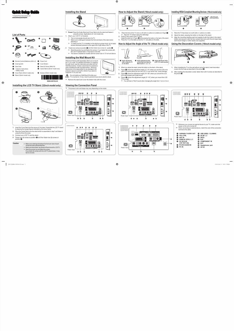
Viewing the Connection Panel
Installing the Stand
➣ Preset: Place the Guide Stand and Cover Neck onto the stand and fasten itusing the screws. Applicable to 32 inch model only.
1. Attach your LCD TV to the stand.
➣ Two or more people should carry t he TV.
➣Make sure to distinguish between the front and back of the stand whenattaching it.
➣ To make sure the TV is installed on the stand at a proper level, do not applyexcess downward pressure to the upper left of right sides of the TV.
2. Fasten two screws at position 1 and then fasten two screws at position2.
➣ Stand the product up and fasten the screws. If you fasten the screws withthe LCD TV placed down, it may lean to one side.
➣ The stand is installed for models with the screen size of 37 inch and above.
Installing the Wall Mount Kit
Wall mount items (sold separately) allow you to mountthe TV on a wall. For detailed information on installingthe wall mount, see the instructions provided with theWall Mount items. Contact a technician for assistancewhen installing the wall mounted bracket. SamsungElectronics is not responsible for any damage to theproduct or injury to yourself or others if you select toinstall the TV on your own.
Do not install your Wall Mount Kit while yourTV is turned on. It may result in personal injury due to electric shock.
➣ Remove the stand and cover the bottom hole with the cover.
BN68-02879A-00
How to Adjust the Stand (19inch model only)
1. Place the front of the TV onto a s oft cloth or cushion on a table as in Figure 1.
➣ Align the TV bottom along the table edge.2. Press on the center of the TV back.
Adjust the stand as in Figure2 while pressing the button on the back of the stand.3. Place the TV on the table so that the TV sits safely on the table.
How to Adjust the Angle of the TV (19inch model only)
➣ When you adjust the stand, press the button on the back of the stand.
1. Figure 1 shows the adjustment angle (-2°~14°) when you use the LCD on itsstand. Excessive tilting can turn the LCD TV over which may cause damage.
2. Figure 2 shows the adjustment angle (14°~80°) when you convert the LCDfrom stand-based use to wall-mount.
3. Figure 3 shows the adjustment angle (0°~10°) when you mount the LCDTV to a wall.
➣ You will hear a "Click" sound when changing the angle from 1 to 2 or 3 to 2.
Installing VESA Compliant Mounting Devices (19inch model only)
1. Place the TV face down on a soft cloth or cushion on a table.
2. Adjust the stand, pressing the button on the back of the stand.
3. Align the mounting interface pad (not supplie d) with the holes in the standbottom and secure it with the four screws that come with the arm-type base,
wall mount hanger or other bases (not supplied).
1
Button
2
Mounting pad(Sold separately)
1 2
➢ Make sure to distinguish between the front and back of each
component when assembling them.
➢ Make sure that at least two persons lift and move the LCD TV.
➢ Stand the product up and fasten the screws.
If you fasten the screws with the LCD TV placed down, it may
lean to one side.
Caution
Using the Decoration Covers (19inch model only)
1. When installing the TV on the wall without using the stand, insert decorationcovers into the holes as described in the picture 1.
2. After inserting the decoration covers, fasten them with 4 screws as described inthe picture 2.
Installing the LCD TV Stand (32inch model only)
1. Insert the Cover Neck into the groove of t he stand. Assemble the LCD TV standby aligning the triangle gures indicated by the arrow marks.
2. Place the Guide Stand onto the stand which is assembled in step1 and fasten itusing the threeⓐ screws.
3. Connect your LCD TV and the stand.
4. Fasten twoⓑ screws at position 1 and then fasten two ⓑ screws atposition 2.
1
Front
Back
2
Front
Back
3
Position2
Position1
4
➣ The product color and shape may vary depending on the model.
➣ Whenever you connect an external device to your TV, make sure thatpower on the unit is turned off.
➣ When connecting an external device, match the color of the connectionterminal to the cable.
1 VARIABLE AUDIO OUT
2 VOL-CTRL
3 ANT IN
4 HDMI IN 1(DVI), 2, 3
5 5V DC/2.5A(12V DC/1.5A)
6 PC/DVI AUDIO IN
7 PC IN
8 USB (HDD) / CLONING
9 AV IN 1, 2
0 DATA
! RJP
@ COMPONENT IN
# EXT
$ Headphones jack
% HP-ID
3
0!@$%
HDMI I N 3
21
ANTIN 4
8
9
#
7
4 6
Power Input
HDMI I N 3
ANTIN 4
8
9
5Vdc/2.5A(12Vdc/1.5A)
1 32 4 765
0
!@#$%
Power Input
LE32C452C4HXXC
LE32C453C4HXXC
LA32C457C6HXZN
LA37C457C6HXZN
LA40C457C6HXZN
LE26C452C4HXXC
LE26C453C4HXXC
LA26C457C6HXZN
LE32C457C6HXXC
LE37C457C6HXXC
LE40C457C6HXXC
0!@$%
HDMI I N 3
ANTIN 4
8
9
#
1 32 4 76
Power Input
4 7
0!@$%
HDMI I N 3
1 2 3
ANTIN 4
8
9
65
5Vdc/2.5A(12Vdc/1.5A)
#
Power Input
LE26C457C6HXXC
Power Input
$ 8
AVIN
4 6 7
9
3
0@#
LE19C452C4HXXC
LE19C453C4HXXC
LE22C452C4HXXC
LE22C453C4HXXC
LE22C457C6HXXC
1
6
2 3 4
7
1 2
1 Angle adjustmentwhen using the TVon its stand.
2 Angle adjustment whenconverting from Stand toWall mount (1→3, 3→1)
3 Angle adjustment whenLCD TV is wall-mounted
8
0 !9
5
[QSG]BN68-02879A-00.indd 1 2010-04-03 오후 12:20:35
8/13/2019 Samsung TV Into
http://slidepdf.com/reader/full/samsung-tv-into 2/2
Specications
Items Specication Comment
TV System PAL, SECAM, DVB-T/C
Audioout
Speaker out
19inch / 22inch : 3W x 2
26inch : 5W x 2
32inch / 37inch / 40inch : 10W x 2
Variable Audio 4W mono 8 ohm SPK'RCA Jack output
BTL Sound output
Audio out 500mVrms Phone Jack, Monitor out
DC out5V out Max 2.5A Initial output Voltage
12V out Max 1.5A Change output voltage
Input
Component Y, Pb, Pr , Audio-L/R
PC D-sub, Audio-L/R
A/V Audio Video Jack
EXT Scart Jack
HDMI Compatible with the HDMI Specications
Antenna 75 ohm Unbalanced, Din Jack VHF/UHF/CATV
DataDATA RJ-12
RJP RS232 Jack Pack Only, TeleAdapt RJP Only
Operating temperature 10°C ~ 40°C (50°F ~ 104°F)
Operating Humidity 10% ~ 80% non-condensing
Storage Temperature -20°C ~ 45°C (-4°F ~ 113°F)
Storage Humidity 5% ~ 95% non-condensing
➣ Design and specications are subject to change without prior notice.
➣ For the power supply and Power Consumption, refer to the label attached to the product.
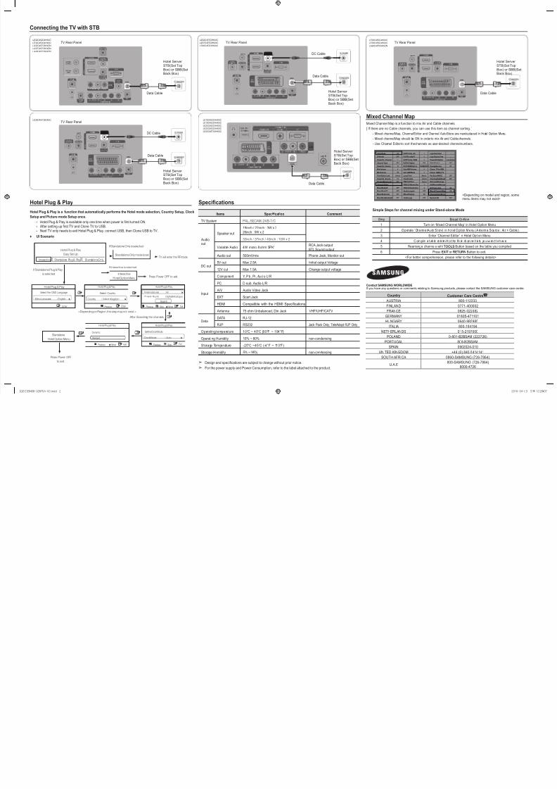
Connecting the TV with STB
Hotel Plug & Play
Hotel Plug & Play is a function that automatically performs the Hotel mode selection, Country Setup, Clock
Setup and Picture mode Setup once.
- Hotel Plug & Play is available only one time when power is rst turned ON.
- After setting up rst TV and Clone TV to USB.
- Next TV only needs to exit Hotel Plug & Play, connect USB, then Clone USB to TV.
♦ UI Scenario
Contact SAMSUNG WORLDWIDE
If you have any questions or comments relating to Samsung products, please contact the SAMSUNG customer care centre.
Country Customer Care Centre
AUSTRIA 800-112233
FINLAND 0771-400002
FRANCE 0825-022082
GERMANY 01805-471101
HUNGARY 0640-985985
ITALIA 800-194194
NETHERLANDS 015-2197000
POLAND 0-801-B2BSAM (222726)
PORTUGAL 808-B2BSAM
SPAIN 0902024-010
UNITED KINGDOM +44 (0) 845 8414141
SOUTH AFRICA 0860-SAMSUNG (726-7864)
U.A.E800-SAMSUNG (726-7864)
8000-4726
LE32C452C4HXXC
LE32C453C4HXXC
LA32C457C6HXZN
LA37C457C6HXZN
LA40C457C6HXZN
LE26C452C4HXXC
LE26C453C4HXXC
LA26C457C6HXZN
LE32C457C6HXXC
LE37C457C6HXXC
LE40C457C6HXXC
ETHMODEM
ANT1 IN(AIR)
ANT2 IN(CABLE)
ANT1IN(AIR)
ANT2IN(CABLE)
Data Cable Data Cable
TV Rear Panel TV Rear Panel
Hotel Server
STB(Set Top
Box) or SBB(SetBack Box)
Hotel Server
STB(Set Top
Box) or SBB(SetBack Box)
Data Cable
TV Rear Panel
Hotel Server
STB(Set TopBox) or SBB(Set
Back Box)
ANTIN
ANT IN 5Vdc/2.5A
(12Vdc/1.5A)
ETHMODEM
DC-POWERDC Cable
ETHMODEM
ANTIN
ANTIN
LE26C457C6HXXC
Data Cable
TV Rear Panel
Hotel ServerSTB(Set Top
Box) or SBB(Set
Back Box)
DC Cable ANTIN
ANTIN 5Vdc/2.5A(12Vdc/1.5A)
ETHMODEM
DC-POWER
LE19C452C4HXXC
LE19C453C4HXXC
LE22C452C4HXXC
LE22C453C4HXXC
LE22C457C6HXXC
Data Cable
Hotel Server
STB(Set Top
Box) or SBB(Set
Back Box)
AVIN
ETHMODEM
AVIN
Standalone Only mode is set TV will enter the RF mode.
Interactive
Hotel Option MenuPress Power OFF to exit.
If Standalone Plug & Play
is selected
Press Power OFF
to exit.
If Standalone Only is selected
If Interactive is selected
After Searching the channels.
<Depending on Region, this step may not exist.>
Standalone
Hotel Option Menu
Hotel Plug & Play
Easy Set Up
Interactive Standalone Plug & Play Standalone Only
Hotel Plug & Play
Select the OSD Language.
MenuLanguage : English r
Enter
Hotel Plug & Play
AntennaSource :Air r
Ch an ne l So ur ce :Digital&Analogue
UMove
Search
ExitSkip
D PreviousA
Hotel Plug & Play
SettheClockMode.
ClockMode : Auto r
SkipDPreviousA Exit
Hotel Plug & Play
Dynamic
Standard
PreviousA ExitU Move
U
Hotel Plug & Play
Select Country.
Country : United Kingdom r
EnterPreviousA
Mixed Channel Map
Simple Steps for channel mixing under Stand-alone Mode
Step Broad Outline
1 Turn on ‘Mixed Channel Map’ in Hotel Option Menu
2 Operate ‘Channel Auto Store’ i n Hotel Option Menu (Antenna Source : Ai r + Cable)
3 Enter ‘Channel Editor’ in Hotel Option Menu
4 C om pi le a t ab le re la te d t o t he n al ch an ne l l is ts yo u w an t t o h av e
5 Rearrange channels with TOOLS Button based on the table you compiled
6 Press EXIT or RETURN Button to exit.
<For better comprehension, please refer to the following details>
Mixed Channel Map is a function to mix Air and Cable channels.
[ If there are no Cable channels, you can use this item as channel sorting. ]
- Mixed channel Map, Channel Editor and Channel Auto Store are newly placed in Hotel Option Menu.
- Mixed channel Map should be ON in order to mix Air and Cable channels.
- Use Channel Editor to sort the channels as user-desired channel numbers.
<Depending on model and region, somemenu items may not exist>
Hotel Mode ON RJPPriority AV 1 Logo Download ...
SI Vendor OFF RJPPriorityPC 2 Logo Display Time ...
PowerOn Channel 1 RJPPriority HDMI 3 Power On Option Last Option
Channel Type ATV RJPAV Option AV1 Auto Source OFF
PowerOn Volume 10 RJPHDMI Option HDMI1/DVI Energy Saving Off
Min Volume 0 Sub AMPVolume 6 Clone : TV to USB
MaxVolume 100 Sub AMPMode 2 Clone : USB to TV
Panel Button Lock Unlock Local Time Manual Pan Euro MHEG OFF
PowerOn Source TV TimeFormat 12Hour Cloning Data Reset OFF
Picture Menu Lock OFF PMOLEDTest Failure WelcomeMessage
Channel Editor PMOLED Mormal Dim. 3 EditWelcomeMessage
Music Mode AV OFF PMOLEDStandbyDim. 2 DCPowerOut 5V
Music Mode PC OFF Audio Loop In OFF Mixed Channel Map ON
Music Mode Comp OFF Menu Display ON Channel Auto Store
Music Mode Backlight OFF Hotel Logo OFF Dynamic SI OFF
[QSG]BN68-02879A-00.indd 2 2010-04-03 오후 12:20:37