Embed Size (px)
Citation preview
Page 1 of 2
SAN FRANCISCO UNIFIED SCHOOL DISTRICT FACILITIES DESIGN & CONSTRUCTION
Bid Package 3
Boiler Replacements
Mission High School and Flynn Elementary School
ADDENDUM NO. 2
PROJECT: Mission HS
3750 18th
Street DATE: 24 MARCH 2015
San Francisco, 94114
Flynn ES
3125 Cesar Chavez Street
San Francisco, 94110
OWNER: San Francisco Unified School District DSA FILE NO.: N/A 135 Van Ness Avenue
San Francisco, CA 94103 DSA APP. NO.: N/A
Notice is hereby given to all prospective bidders that plans and specifications on the subject project are modified as hereinafter set forth. This Addendum shall be attached to and form a part of the plans and specifications. All bidders must acknowledge receipt of this addendum on the Bid Form. In case of difference with previous addenda or communications, this addendum takes precedence.
It is the responsibility of all bidders to notify all subcontractors from whom they request bids and from whom they accept bids of all changes contained in this addendum.
REPLACE SPECIFICATIONS WITH NEW SECTIONS LISTED BELOW: Section 15510: Heating Boilers
Section 15900: Instrumentation and Control Performance Specifications
REPLACE DRAWINGS WITH NEW DRAWINGS LISTED BELOW:
Drawing M0.02: Schedules – Mechanical
Drawing M1.11: Basement Demolition Plan – Leonard R. Flynn – Mechanical
Drawing M1.21: Basement Demolition Plan – Mission High School – Mechanical
Drawing M2.21: Basement Floor Plan – Mission High School – Mechanical
Drawing M5.11: Controls – Leonard Flynn ES – Mechanical
Drawing M5.12: Controls – Leonard R. Flynn ES – Mechanical
Drawing M5.21: Controls – Mission High School - Mechanical
Page 2 of 2
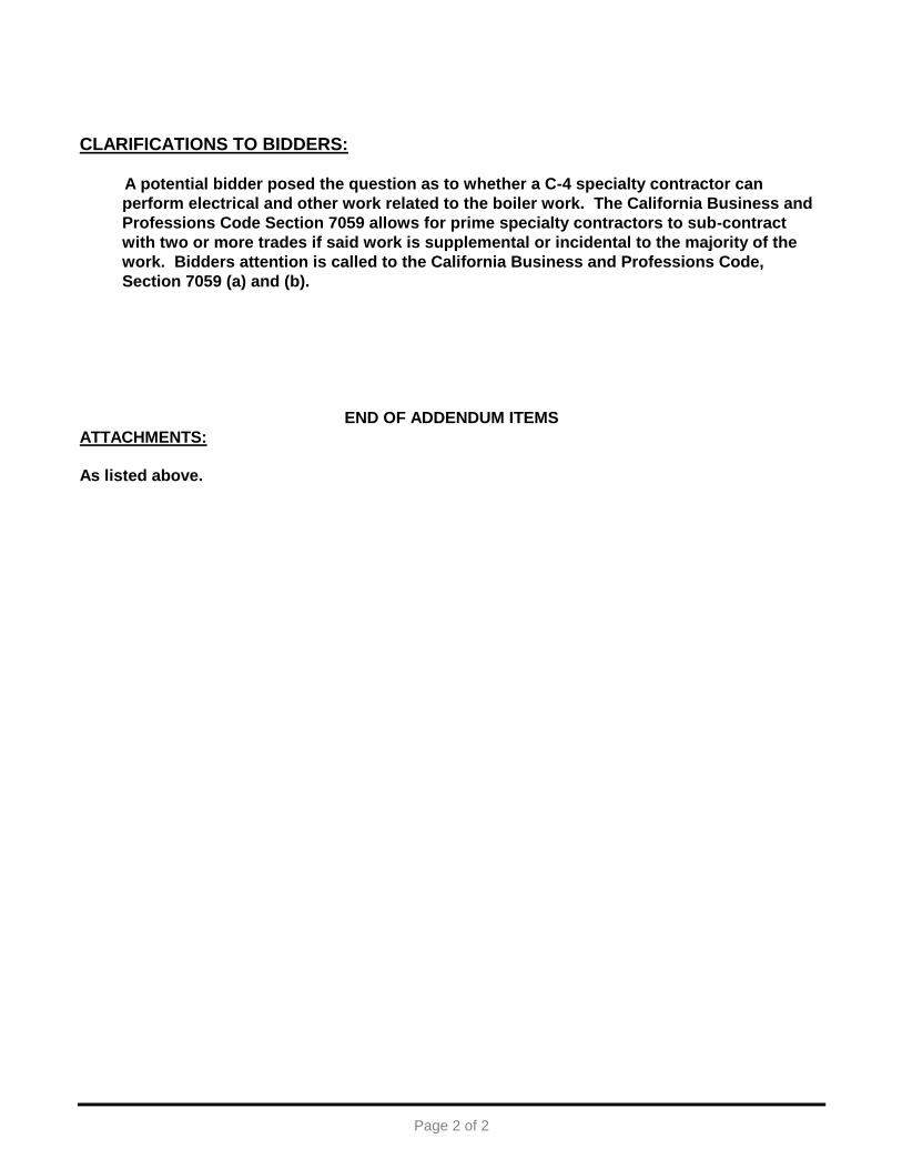
CLARIFICATIONS TO BIDDERS:
A potential bidder posed the question as to whether a C-4 specialty contractor can
perform electrical and other work related to the boiler work. The California Business and
Professions Code Section 7059 allows for prime specialty contractors to sub-contract
with two or more trades if said work is supplemental or incidental to the majority of the
work. Bidders attention is called to the California Business and Professions Code,
Section 7059 (a) and (b).
END OF ADDENDUM ITEMS
ATTACHMENTS:
As listed above.
San Francisco Unified School District Leonard Flynn Elementary School Mission High School
Boiler Replacement Projects Addendum 2
3/24/15
HEATING BOILERS 15510 - 1
SECTION 15510
HEATING BOILERS
PART 1 - GENERAL
1.1 SUMMARY
A. Work included:
1. Cast Iron Boilers
2. Emergency Stop Pushbutton Switch
1.2 RELATED SECTIONS
A. Contents of Division 15, HVAC and Division 01, General Requirements apply to this
Section.
B. In addition, reference the following:
1. Section 15185, Steam and Condensate Piping and Pumps
2. Section 15550, Breechings, Chimneys and Stacks
3. Section 16110, Equipment Wiring 1.3 REFERENCES AND STANDARDS
A. References and Standards per Section 15020, HVAC Basic Requirements and Division
01, General Requirements.
1.4 SUBMITTALS
A. Submittals as required by Section 15020, HVAC Basic Requirements and Division 01,
General Requirements.
B. In addition, provide:
1. Product Data: Provide data indicating general assembly, components, controls, safety controls, flue venting system, and wiring diagrams with electrical characteristics and connection requirements, and service connections.
2. Shop Drawings: Indicate general assembly, components, controls, flue venting, safety controls, and wiring diagrams with electrical characteristics and connection requirements, and service connections.
3. Manufacturer's Instructions: Indicate assembly, support details, connection requirements, and include start-up instructions.
4. Manufacturer's Field Reports: Indicate condition of equipment after start-up including control settings and performance chart of control system.
5. Warranty: Submit manufacturer warranty and ensure forms have been completed in Owner's name and registered with manufacturer.
6. Provide documentation indicating compliance with local air quality management district.
San Francisco Unified School District Leonard Flynn Elementary School Mission High School
Boiler Replacement Projects Addendum 2
3/24/15
HEATING BOILERS 15510 - 2
7. Emissions Testing Documentation: Submit Bay Area Air Quality Management District emissions test documentation showing acceptable emissions levels for submitted boiler.
1.5 QUALITY ASSURANCE
A. Quality assurance as required by Section 15020, HVAC Basic Requirements and
Division 01, General Requirements.
B. In addition, meet the following:
1. Manufacturer Qualifications: Company specializing in manufacturing the type of products specified in this Section, with minimum three years of documented experience.
2. Installer Qualifications: Company specializing in installing and servicing the products specified in this Section, with minimum three years of experience and approved by manufacturer.
3. Air Quality: Provide documentation showing compliance with local Air Quality Management District.
4. Equipment must meet local air quality management district requirements. Do not bid equipment that does not comply.
5. The boiler(s) shall be field assembled by a C4 Licensed Contractor and hydrostatically tested in accordance with the manufacturer’s installation instructions. All work shall be completed in a neat and workmanlike manner.
1.6 WARRANTY
A. Warranty of materials and workmanship as required by Section 15020, HVAC Basic
Requirements and Division 01, General Requirements.
B. In addition, provide:
1. Vertical Tubeless Boiler: 5-year material and workmanship on pressure vessel.
2. Warranty: Submit manufacturer warranty and ensure forms have been completed in Owner's name and registered with manufacturer.
PART 2 - PRODUCTS
2.1 MANUFACTURERS
A. Cast Iron Boilers:
1. Peerless Boiler
B. Emergency Stop Pushbutton Switch:
1. Group Schneider/Square D Class 9001 SB5 Family
2. Eaton
3. Siemens
4. General Electric
5. Or approved equivalent.
San Francisco Unified School District Leonard Flynn Elementary School Mission High School
Boiler Replacement Projects Addendum 2
3/24/15
HEATING BOILERS 15510 - 3
2.2 CAST IRON BOILERS
A. Manufactured Units:
1. Steam Boilers: Suitable for forced draft with insulated jacket, sectional cast iron heat exchanger, natural gas burning system, refractory, controls, and boiler trim.
2. Provide water wall design consisting of water backed combustion area with water circulating around firebox. Refractory chamber or separate base not required.
B. Fabrication:
1. Assembly: Cast iron Sections with 15 PSI steam ASME Boilers and Pressure Vessels Code rating, assembled with push nipples or gaskets and draw rods.
2. Access: To flue passages for cleaning and flame observation ports.
3. Jacket: Glass fiber insulated steel jacket, finished with factory applied baked enamel.
4. Tankless Water Heater: Finned, copper tube heat exchanger mounted in top port.
5. The boiler sections shall be assembled using individual draw rods between each section for ease of assembly and to evenly distribute tension between the sections.
6. Each section shall be evenly spaced and high temperature sealing rope shall be used to provide a permanent gas-tight seal between the sections.
7. Graphite port connectors shall be used at each port opening to provide a permanent water-tight seal between the sections.
8. The boiler(s) sections shall be of a wet base design to provide a complete water backed heating surface around combustion chamber area for maximum heat transfer and low floor temperatures.
9. The boiler(s) shall be furnished with side cleanout plates for ease of inspection and cleaning of the flueways. The cleanout plates shall be sealed to the boiler with high temperature sealing rope.
10. The boiler(s) shall be furnished an integral cast iron flue collector a and a cast iron rear flue outlet.
11. The boiler(s) shall be provided with an adjustable damper which is capable of being securely locked in position to pressurize the boiler for forced draft operation.
12. The boiler(s) shall have no requirement for refractory chamber liner and target wall to protect the base of the firebox and the back section.
13. The boiler(s) shall be provided with an insulated burner mounting plate with the necessary tappings for mounting the burner(s).
14. The boiler(s) shall be provided with temperature resistant or Pyrex glass front and rear flame observation ports to permit visual inspection of the burner flame.
15. The boiler(s) shall be provided with an insulated steel flush jacket with a painted finish. The jacket shall be designed to permit installation after the supply and return piping is connected.
16. The boiler(s) shall be furnished with steel angle rails to provide a level and smooth surface for ease of assembly.
17. Boiler Controls shall include but not be limited to those as required by State of California Boiler Safety Orders, ASME. Operating limit control, safety high limit control with manual reset, combination pump controller and low water cut-off, electronic low water cut-off with test feature and manual reset, low fire hold
San Francisco Unified School District Leonard Flynn Elementary School Mission High School
Boiler Replacement Projects Addendum 2
3/24/15
HEATING BOILERS 15510 - 4
aquastat, 15 PSI ASME pressure relief valve, water level sight glass with gauge cocks.
C. Steam Boiler Trim:
1. ASME rated pressure relief valve, 15 psig.
2. Steam pressure gauge, 0 to 30 PSIG.
3. Water column gauge glass set with cocks.
4. Low water cut-off to prevent burner operation when boiler water drops below safe level and boiler condensate return pump control to maintain water level by controlling pump operation.
5. Operating pressure controller for burner to maintain steam pressure setting.
6. High limit pressure control with manual reset for burner to prevent steam pressure from exceeding system pressure.
D. Fuel Burning System:
1. Burner Operation: Hi-Low with low fire position for ignition.
2. Burner: Low NOx natural gas force draft burner using induced FGR for low NOx attainment, PowerFlame model LNICR4-G 5 horsepower motor of 208/3/60 minimum inlet gas pressure of 5.5” wc and no more then 14” wc. Top vertical mounted UL burner control panel to house Honeywell RM7897A flame safe guard burner motor starter, necessary relays and fuses. In addition, there shall be failure indicator lamps with push to test buttons, common relays for remote EMCS monitoring the following conditions: power on, flame on, call for heat, flame failure, high gas pressure, low gas pressure, low water. Unassembled burner gas train consists of Pilot and Main gas shut-off cocks, Pilot and Main gas pressure regulators, high and low gas pressure lock out switches, dual motorized Honeywell gas valves, firing gas cock. 24 Volt relay is included for remote EMCS on/off control of boiler.
3. FGR: FGR control valve is premounted and wired to the burner. Contractor is responsible to provide and pipe 6” AL29-4C between burners FGR inlet connection to the boiler exhaust pipe.
4. Gas Burner: Forced draft for natural gas, adjustable combustion air supply, gas pressure regulator, gas valves, manual shut-off, intermittent spark or glow coil ignition, flame sensing device and automatic 100 per cent shut off. Burner includes drawer assembly with flame retention head and diffuser, blower and motor, orifices, gas train, main safety gas valve and low-high pressure gas switches.
5. Gas Burner Safety Controls: Energize ignition, limit time for establishment of flame, prevent opening of gas valve until pilot flame is proven, stop gas flow on ignition failure, energize blower motor, and after air flow proven and slight delay, allow valve to open.
6. Controls: Pre-wired, factory assembled electronic controls in control cabinet with flame scanner or detector, programming control, relays, and switches. Provide pre-purge and post-purge ignition and shut-down of burner in event of ignition pilot and main flame failure with manual reset.
San Francisco Unified School District Leonard Flynn Elementary School Mission High School
Boiler Replacement Projects Addendum 2
3/24/15
HEATING BOILERS 15510 - 5
2.3 EMERGENCY STOP PUSHBUTTON SWITCH
A. Provide 40mm diameter turn-reset red pushbutton operator with contact blocks to
disconnect power to the boiler burner controls and gas service. Basis-of-Design: Square D Class 9001 Family XB5.
PART 3 - EXECUTION
3.1 INSTALLATION
A. Install boiler in accordance with manufacturer’s instructions.
B. Provide connection of natural gas service in accordance with requirements of NFPA 54
and applicable codes, and fuel oil tanks. Pipe gas vents to atmosphere.
C. Install boiler on concrete housekeeping base, sized minimum 4-inches larger than
boiler base.
D. Pipe relief valves to nearest floor drains.
E. Pipe relief valves to outdoors.
F. Provide for connection to electrical service.
G. Provide all wiring between control panels and devices and unit.
H. Mount thermometer in boiler breeching within 12 inches of flue nozzle.
I. Pipe boiler drains to nearest floor drains.
3.2 SYSTEM START-UP
A. Provide the services of manufacturer's field representative for starting and testing unit.
B. After installation and pipe flushing, boil out boilers using chemical and procedure as recommended and supervised by boiler manufacturer.
C. Manufacturer shall provide report verifying that boilers have been inspected, cleaned
and tested according to their recommendations. 3.3 CLOSEOUT ACTIVITIES
A. Train operating personnel in operation and maintenance of units.
B. Provide the services of manufacturer's field representative to conduct training.
HEATING BOILERS 15510 - 6
San Francisco Unified School District Leonard Flynn Elementary School Mission High School
Boiler Replacement Projects Addendum 2
3/23/15
3.4 BOILER SHUTDOWN
A. Remote switch: Install shutdown switch to disconnect power to the boiler burner
controls and gas service in room. Install pushbutton under clear, impact-resistant flip lid. Provide red phenol label "Emergency Shutdown" locate label above pushbutton. Pushbutton to be mounted by latch side of each boiler/mechanical room door within interior of the room, unless otherwise directed by AHJ. Provide electrical wiring and raceway as necessary for installation. Provide additional relays and wiring to cut power to gas solenoid valves in the room not integral to boilers. Reference drawings for gas solenoid valve locations.
END OF SECTION
San Francisco Unified School District Leonard Flynn Elementary School Mission High School
Boiler Replacement Projects Addendum 2
3/24/15
INSTRUMENTATION AND CONTROL PERFORMANCE SPECIFICATIONS 15900 - 1
SECTION 15900
INSTRUMENTATION AND CONTROL PERFORMANCE SPECIFICATIONS
PART 1 - GENERAL
1.1 SUMMARY
A. Work Included: Design (including detailed sequence of operations), materials,
installation and testing of:
1. Communications
2. Operator Interface
3. Controller Software
4. BAS Graphics
5. Building Controllers
6. Application Specific Controllers
7. Advanced Application Controllers
8. Input/Output Interface
9. Power Supplies and Line Filtering
10. Control Panels
11. Auxiliary Control Devices
12. Wiring and Raceways
B. This is a performance specification and Contractor is responsible for design tasks and engineering.
1.2 RELATED SECTIONS
A. Contents of Division 15, HVAC and Division 01, General Requirements apply to this
Section.
1.3 REFERENCES AND STANDARDS
A. References and Standards as required by Section 15020, HVAC Basic Requirements
and Division 01, General Requirements.
B. In addition, meet the following:
1. Current edition of UL 916 Underwriters Laboratories Standard for Energy Management Equipment, Canada and the US.
2. Current edition of FCC Part 15, Subpart J, Class A. 1.4 SUBMITTALS
A. Submittals as required by Section 15020, HVAC Basic Requirements and Division 01,
General Requirements.
B. In addition, provide:
San Francisco Unified School District Leonard Flynn Elementary School Mission High School
Boiler Replacement Projects Addendum 2
3/24/15
INSTRUMENTATION AND CONTROL PERFORMANCE SPECIFICATIONS 15900 - 2
1. Prepare and submit a detailed schedule of work. Schedule to identify milestones such as equipment submittals, control panel diagrams, color graphic panel displays, Interlock.
2. Wiring diagrams, control program sequence software flow chart diagrams, conduit layout diagrams, device location diagrams, equipment and component deliveries, installation sequencing, controller startup, point to point startup, control programming, sequence testing, commissioning/acceptance testing and training.
3. Submit design drawings, sequences of operation, program listings, software flow charts and details for each typical piece of equipment and system being controlled. No work to be initiated or fabrication of any equipment started prior to the Owner's Representatives return of REVIEWED submittals. a. Sequence of Operation: Please note that the sequence of operation
included in the design documents is intended only to communicate the Engineers’ general control intent and is not to be used as a direct reference for programming of the EMS system. Verbatim duplication of the Engineer’s Sequence of Operation on the submittals is discouraged and may result in non-approval of the submittal. Sequence of operation on submittals shall accurately detail the system’s intended programming, and shall include details of all enhancements, adjustments, or deviations from the Engineer’s sequence of operation. Submitted sequence of operation shall be written with a logical and organized format and flow. Sequence of operation language shall be detailed, clear, and unambiguous. Point descriptors and point nomenclature referenced in the submitted sequence of operation shall match those (to be) actually programmed. As-built submittal Sequence of Operation shall include all modifications to the programming made as a result of any addendum, bulletins, RFI’s, change orders, and commissioning.
4. Format: Make each submittal in one complete and contiguous package. Partial or unmarked submittals will be rejected without review.
5. Submit Manufacturers Data as Follows: a. Complete materials list of items proposed to be furnished and installed. A
complete Bill of Materials, listing materials, components, devices, wire and equipment are required for this work. The Bill of Materials to be separate for each controller on its own page(s) and to contain the following information for each item listed: 1) Manufacturer's Name and Model number with furnished options
highlighted. 2) Quantity of each by controller location. 3) Description of product (generic). 4) Specified item. 5) Operating range or span. 6) Operating point or set point.
b. Manufacturer's specifications and other data required demonstrating compliance with the specified requirements, including but not limited to: Catalog cuts, technical data and descriptive literature on hardware, software, and system components to be furnished.
c. The data to be clearly marked and noted to identify specific ranges, model numbers, sizes, and other pertinent data. Submit printed manufacturer's technical product data for each control device furnished, indicating
San Francisco Unified School District Leonard Flynn Elementary School Mission High School
Boiler Replacement Projects Addendum 2
3/24/15
INSTRUMENTATION AND CONTROL PERFORMANCE SPECIFICATIONS 15900 - 3
dimensions, capacities, performance characteristics, electrical characteristics, finishes of materials and including printed installation instructions and start-up instructions.
d. Unless specifically called for otherwise, provide bound copies of catalog cuts for standard products, not requiring specifically prepared Shop Drawings, for the following: 1) Wire and Cable, Class II 2) Face Plates for Devices 3) Disconnect Switches for Power Control
e. Where more than one item, size, rating or other variations appear on a catalog cut sheet, clearly identify items to be provided. These items to be properly indexed and referenced to identification numbers, designations and/or details on the Drawings.
6. Shop Drawings: Submit shop drawings for each controlled system, depicting the following information: a. Schematic flow diagram of system showing fans, pumps, coils, dampers,
valves and other control/monitoring devices. b. Label each control device with initial setting or adjustable range of control.
Label points in schematic diagrams with termination at corresponding controller.
c. Electrical Wiring: Clearly differentiate between portions of wiring that are factory installed and portions of be field-installed.
d. Details of control panel faces, including controls, instruments, and labeling. e. Interfaces to equipment furnished under other Sections identifying numbers
of wires, termination location, voltages and pertinent details. Responsibility for each end of the interfaces to be noted on these drawings whether or not they are a part of this Section.
7. Equipment locations, wiring and piping schematics, details, panel configurations, sizes, damper motor mounting details, valve schedules, and a points list keyed to specific hardware submittals. Control wiring depicted as fully annotated ladder diagrams with terminations identified, completely configured as to the exact panel, wiring, relay, switch, and component configuration.
8. Tag Number Lists: Develop instruments tag number system and submit list for approval. Coordinate methods and number block with the Owner Representative.
9. Format the Shop and Field Drawings to Include: a. A Title Sheet containing a drawing list, abbreviations list, symbols list, site
and vicinity maps for project location and schedules. b. Floor Plans showing proposed device locations and device nomenclatures. c. A Riser Diagram illustrating conduit relationships between devices shown
on the Floor Plans. Show device nomenclatures. d. A Single-Line Diagram for each system showing signal relationships of
devices within the system. Show device nomenclatures. e. A Wiring Diagram for each assembly, enclosure or free standing device,
showing: 1) The Devices Within 2) Wiring Connections 3) Wire Identification 4) Voltage Levels 5) Fuse Ratings
f. Operations and Maintenance Manuals:
San Francisco Unified School District Leonard Flynn Elementary School Mission High School
Boiler Replacement Projects Addendum 2
3/24/15
INSTRUMENTATION AND CONTROL PERFORMANCE SPECIFICATIONS 15900 - 4
1) Following approval of Shop Drawings of control equipment and prior to acceptance of control work, prepare Operating and Maintenance manuals describing operating, servicing, and maintenance requirements of control systems and equipment installed under this Section, in accordance the General and Special Conditions of these Specifications.
2) Information contained in the manual for the above equipment to include the following: a) Manufacturer's catalog cuts and printed descriptive bulletins. b) Manufacturer's installation, operating, and maintenance
instruction booklets. Complete instructions regarding the operation and maintenance of equipment involved.
c) Instrument calibration certificates. d) Parts list and costs. e) Complete nomenclature of replaceable parts, list of
recommended spare parts for 12 months operation, their part numbers, current cost and name and address of the nearest vendor of replacement parts.
f) Name, address and telephone number for closest source of spare parts.
g) Wiring and schematic diagrams. h) Include final record copies of shop drawings. i) Copy of guarantees and warranties issued for the various items
of equipment, showing dates of expiration. j) Reduced plans, diagrams, and control schematics. k) Copies of test results. l) Control System Operating Manual including: point of summary
and point data base; complete printout of program listings; magnetic tape CD or DVD backup of Field Control Cabinet programs; cabinet layout; hard copy of graphic screens; hard copy of specified reports.
g. A final Bill of Quantities including a separate schedule for portable equipment, if delivered as part of this work.
h. Performance, Test and Adjustment Data: Comprehensive documentation of performance verification according to parameters specified in these specifications.
i. Record Drawings: Comply with Division 01, General Requirements and Section 15020, HVAC Basic Requirements. Provide complete as-built submittals including "as-programmed" sequence of operation as well as final occupancy schedules.
1.5 QUALITY ASSURANCE
A. Quality assurance as required by Section 15020, HVAC Basic Requirements and
Division 01, General Requirements.
B. In addition, meet the following:
1. Installer Qualifications: Company specializing in performing work of the type specified in this Section with minimum five year's experience in the local area.
San Francisco Unified School District Leonard Flynn Elementary School Mission High School
Boiler Replacement Projects Addendum 2
3/24/15
INSTRUMENTATION AND CONTROL PERFORMANCE SPECIFICATIONS 15900 - 5
Installers required to have successfully completed manufacturer's control system factory training.
1.6 WARRANTY
A. Warranty of materials and workmanship as required by Section 15020, HVAC Basic
Requirements and Division 01, General Requirements. 1.7 SYSTEM DESCRIPTION
A. Integration with the Tridium® NiagaraAX Framework shall be accomplished through an
EMS contractor-installed Tridium® NiagaraAX JACE 3E, 6E or 7 as specified in Section 00013. No legacy JACE 2s or 6s will be permitted. The JACE must be connected to the SFUSD intranet via the school’s Ethernet connection. All JACEs installed must comply with the Tridium® NiagaraAX Compatibility Statement (NiCS) with the following requirements:
1. Station Compatibility In= All;
2. Station Compatibility Out = All;
3. Tool Compatibility In = All; 4. Tool Compatibility Out = All.
No restricted-license JACEs are allowed. No substitutions are allowed during either design or construction.
B. If the project involves the removal and reinstallation of existing mechanical systems
that are tied into existing Circon 300-series or Distech Controls controllers, and there are no changes necessary, a Buildings and Grounds representative must be consulted to determine whether new controls must be installed.
C. It is the intent of the District to maintain a minimum spare parts inventory and minimize
the technical expertise required for all field maintenance work. The EMS contractor shall strictly adhere to installing the components detailed in this Section. In the event the manufacturers introduce newer component models, the EMS contractor shall notify the District, and the District shall determine whether they will be acceptable. It shall not be the EMS contractor’s responsibility to supply additional inventory components unless the contractor furnishes and installs alternate equipment accepted by the District, in which case the contractor shall provide 10% spare parts of each component with a minimum of one (1).
D. If the installing contractor removes any controllers during a retrofit, including Circon,
Distech, or Tridium® parts, they must salvage, protect, and return the controllers and all related parts to Buildings and Grounds as soon as these controllers are taken out of service.
E. The EMS contractor shall install the JACE, the LON communications trunk from the
JACE to the Distech field controllers, and the communications trunk from the JACE to the District’s existing Ethernet communication network. The EMS contractor shall coordinate this aspect of the installation with the District’s EMS Supervisor and Information Technology Department.
San Francisco Unified School District Leonard Flynn Elementary School Mission High School
Boiler Replacement Projects Addendum 2
3/24/15
INSTRUMENTATION AND CONTROL PERFORMANCE SPECIFICATIONS 15900 - 6
F. All JACE, router, and EMS server setup and programming, including graphics, shall be accomplished by the EMS contractor. The EMS contractor shall supply all necessary documentation to the District and perform all check-out and commissioning as necessary to ensure a complete and fully functional system.
G. The software version to be installed on the Tridium® NiagaraAX JACE must match the
version on the existing Tridium® NiagaraAX server. The software version installed shall be at or higher than the Tridium® June 2013 release. If the contractor needs to upgrade the version of Tridium® NiagaraAX on the JACE and server, that must be done by the contractor at no additional cost to the District.
H. All graphics, programming, trending, and operator adjustments of Tridium® NiagaraAX
JACEs shall be identical to the greatest extent possible to the District’s existing currently installed EMS server and JACE operations.
I. The installing contractor must provide a fully functional graphical user interface (GUI)
that matches existing systems. Any upgrade or addition to an existing system shall also be fully integrated to match the existing graphical user interface. Contractors must consult with the SFUSD Buildings & Grounds EMS Supervisor to obtain examples of the appropriate existing graphical user interface and the District and the District’s representative must approve the EMS contractor’s proposed format before the EMS contractor may commence work.
J. All equipment and system sequence programming of Distech field controllers shall be
identical to the District’s existing standard sequences of operation. The EMS contractor shall program all controllers to reflect the existing sequence of operations at that site. The EMS contractor must consult with Buildings and Grounds about the appropriate sequence of operations for each site. Any deviation to the existing sequence of operations must be approved by Buildings and Grounds.
K. Control system referenced throughout specifications and drawings as Building
Automation System (BAS), Building Management System (BMS), or Energy Management System (EMS) interchangeably consists of high-speed, peer-to-peer network of DDC controllers, control system server, and/or operator workstation.
L. Control system server and/or operator workstation provides for overall system
supervision and configuration, graphical user interface, management report generation, and alarm annunciation.
M. System supports web browser access to building data. Remote user using standard
web browser be able to access control system graphics and change adjustable set points with proper password.
N. Local Area Network (LAN) either 10 or 100 Mpbs Ethernet network.
O. System will consist of open architecture that is capable of:
1. High speed Ethernet communication using TCP/IP protocol
2. LonTalk protocol.
San Francisco Unified School District Leonard Flynn Elementary School Mission High School
Boiler Replacement Projects Addendum 2
3/24/15
INSTRUMENTATION AND CONTROL PERFORMANCE SPECIFICATIONS 15900 - 7
P. Complete temperature control system to be DDC with electronic sensors and electronic/electric actuation valves and dampers.
Q. Prepare individual hardware layouts, interconnection drawings, building
riser/architecture diagram and sequence of control from the project design data.
R. Design, provide, and install equipment cabinets, panels, data communication network
infrastructure (including cables, conduits, outlets, connections, etc.) needed, and associated hardware.
S. Provide complete manufacturer's specifications for items that are supplied. Include
vendor name and model number of every item supplied.
T. Provide a comprehensive operator and technician training program as described in
these specifications.
U. Provide as-built documentation, operator's terminal software, diagrams, and other associated project operational documentation (such as technical manuals) on approved media, the sum total of which accurately represents the final system.
V. Provide 120V power, voltage power, transformers, etc. for control panels, transformer
panels, and BAS devices. Install per Division 16, Electrical specifications. Power for devices within this specification Section are solely the responsibility of the BAS Contractor.
W. Conduit and raceway systems. Provide per Division 16, Electrical specifications.
1.8 SYSTEM PERFORMANCE
A. Performance Standards - System conforms to following minimum standards over
network connections:
1. Graphic Display: Graphic with 20 dynamic points display with current data within 10 seconds.
2. Graphic Refresh: Graphic with 20 dynamic points update with current data within 8 seconds.
3. Object Command: Devices react to command of binary object within 2 seconds. Devices begin reacting to command of analog object within 2 seconds.
4. Object Scan: Data used or displayed at controller or workstation have been current within previous 6 seconds.
5. Alarm Response Time: Object that goes into alarm be annunciated at workstation within 45 seconds.
6. Program Execution Frequency: Custom and standard applications be capable of running as often as once every 5 seconds. Select execution times consistent with mechanical process under control.
7. Performance: Programmable controllers be able to completely execute DDC PID control loops at frequency adjustable down to once per second. Select execution times consistent with mechanical process under control.
8. Multiple Alarm Annunciation: Each workstation on network receive alarms within 5 seconds of other workstations.
San Francisco Unified School District Leonard Flynn Elementary School Mission High School
Boiler Replacement Projects Addendum 2
3/24/15
INSTRUMENTATION AND CONTROL PERFORMANCE SPECIFICATIONS 15900 - 8
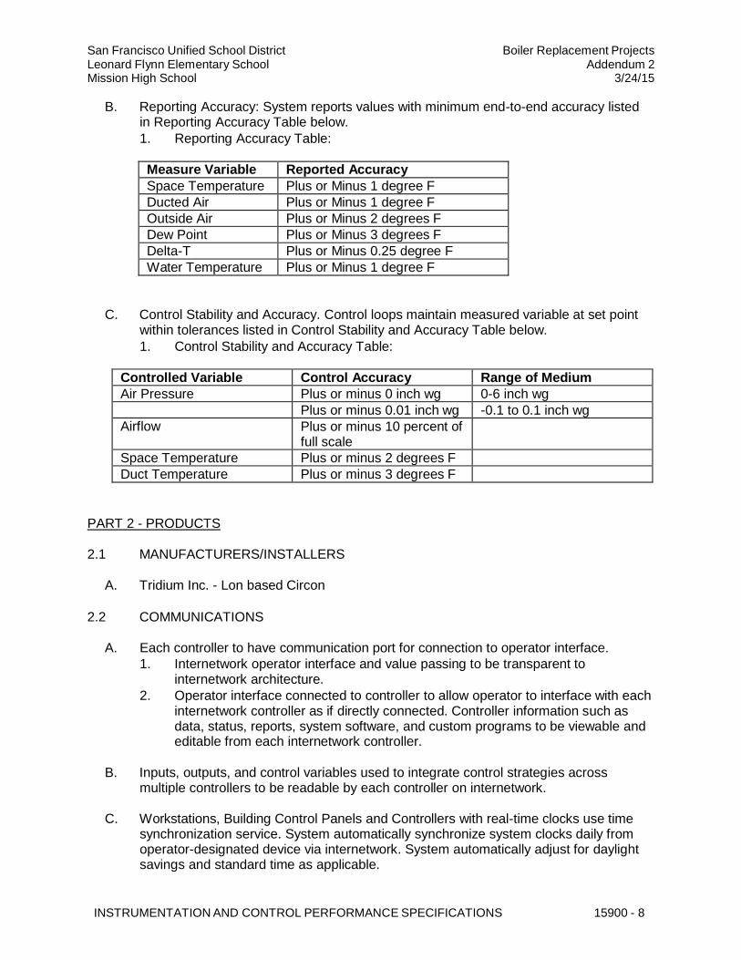
B. Reporting Accuracy: System reports values with minimum end-to-end accuracy listed in Reporting Accuracy Table below.
1. Reporting Accuracy Table:
Measure Variable Reported Accuracy
Space Temperature Plus or Minus 1 degree F
Ducted Air Plus or Minus 1 degree F
Outside Air Plus or Minus 2 degrees F
Dew Point Plus or Minus 3 degrees F
Delta-T Plus or Minus 0.25 degree F
Water Temperature Plus or Minus 1 degree F
C. Control Stability and Accuracy. Control loops maintain measured variable at set point
within tolerances listed in Control Stability and Accuracy Table below.
1. Control Stability and Accuracy Table:
Controlled Variable Control Accuracy Range of Medium
Air Pressure Plus or minus 0 inch wg 0-6 inch wg
Plus or minus 0.01 inch wg -0.1 to 0.1 inch wg
Airflow Plus or minus 10 percent of full scale
Space Temperature Plus or minus 2 degrees F Duct Temperature Plus or minus 3 degrees F
PART 2 - PRODUCTS
2.1 MANUFACTURERS/INSTALLERS
A. Tridium Inc. - Lon based Circon
2.2 COMMUNICATIONS
A. Eac
1.
h controller to have communication port for connection to operator interface.
Internetwork operator interface and value passing to be transparent to
internetwork architecture.
2. Operator interface connected to controller to allow operator to interface with each internetwork controller as if directly connected. Controller information such as data, status, reports, system software, and custom programs to be viewable and editable from each internetwork controller.
B. Inputs, outputs, and control variables used to integrate control strategies across multiple controllers to be readable by each controller on internetwork.
C. Workstations, Building Control Panels and Controllers with real-time clocks use time
synchronization service. System automatically synchronize system clocks daily from operator-designated device via internetwork. System automatically adjust for daylight savings and standard time as applicable.
San Francisco Unified School District Leonard Flynn Elementary School Mission High School
Boiler Replacement Projects Addendum 2
3/24/15
INSTRUMENTATION AND CONTROL PERFORMANCE SPECIFICATIONS 15900 - 9
2.3 OPERATOR INTERFACE
A. Operator Interface. Existing PC-based workstation residing on high-speed network.
Existing system meets LONWORKS standards and is an Niagra Framework system front end.
B. Integration:
1. General: The Building Management System (BMS) shall be a new LONWORKS system that is completely integrated with the existing Niagra Framework Operator Interface "Front End". The new system shall match the existing graphics, schedules, nomenclature, alarms, security, and trends. Communication shall be bidirectional for command of the system from either the new or the existing. Gateways are unacceptable. Third-party integrations are unacceptable.
2. Dynamic Color Graphics: a. New graphics to match existing graphics used for existing buildings on
existing operator interface. b. Real-time color graphic displays dynamic and able to update displays. c. Provide operator ability to change values (setpoints) and states in system
controlled equipment directly from graphic display. d. Provide custom graphics to portray systems installed.
3. System Applications: a. Integrate the following applications at Operator Interface "Front End":
1) Automatic System Database Save and Restore. Store on hard disk copy of current database of each Building Controller. This database automatically updated whenever change is made in any system panel.
2) Manual Database Save and Restore. System operator able to manually save or clear database and initiate download of specified database from/to any panel.
3) System Configuration. Provide method of configuring system to allow for changes or additions by users and performs following tasks: a) Create, delete or modify control strategies. b) Add/delete objects to system. c) Tune control loops through adjustment of control loop
parameters. d) Enable or disable control strategies. e) Generate hard copy records of control strategies on printer. f) Select points to be alarmed and define alarm state. g) Select points to be trended and initiate automatic recording of
values. h) Start/Stop binary objects and adjust analog objects.
4) Security: Operator required to log on to system with user name and password in order to view, edit, add, or delete data. System security selectable for each operator.
5) System Diagnostics: System automatically monitor operation of network connections, building management panels, and controllers. Failure of any device to be annunciated.
6) Alarm Indication and Handling: a) Provide visual means of alarm indication. Alarm indication
becomes highest priority regardless of application(s) running.
San Francisco Unified School District Leonard Flynn Elementary School Mission High School
Boiler Replacement Projects Addendum 2
3/24/15
INSTRUMENTATION AND CONTROL PERFORMANCE SPECIFICATIONS 15900 - 10
a) Objects: System (or subsystem) objects and their current
values. b) Logs: c) Alarm History d) System Messages e) System Events f) Trends
9) Ele trical, Gas, and Weather Report:
b) Provide and archive log of alarm messages to hard drive. Alarm messages to include description of event-initiating object, source, location and time/date of alarm.
7) Trend Logs: Operator able to define custom trend log for any data object and include interval, start time, and stop time. Trend data sampled and stored on building controller panel, be archived on hard disk, and be retrievable for use in spreadsheets and standard database programs. a) System server to periodically gather historically recorded data
stored in the building controllers and archive the information. Archived files to be appended with new sample data, allowing samples to be accumulated.
b) Software to be included that is capable of graphing the trend logged object data. Software capable of creating two-axis (x,y) graphs that display object values relative to time.
c) Operator able to change trend log setup information. This includes the information to be logged as well as the interval at which it is to be logged. Input, output, and value object types in the system may be logged. Provide operations password protected. Setup and viewing may be accessed directly from any and all graphics on which object is displayed.
d) BAS Contractor shall enable trending for any and all system points (physical or virtual) as directed by the Engineer, Owner or Commissioning Authority (CxA). There will be no limit on the number of trended points the BAS Contractor is to set up. BAS Contractor will modify trend setup parameters as directed by the CxA during testing. BAS Contractor shall be proactive and enable trending for all major system points during system startup/programming. BAS Contractor is not to wait for direction to begin trending points. Trend data for each point shall be archived on the main server for a minimum of one year. Trend data archiving shall be enabled immediately upon trend setup, or as soon as communication between the field panel and sever is established. Trend data uploads from field panel to server shall be set up to be automatically performed with sufficient frequency to ensure no data gaps or loss of trend data.
8) Standard Reports: Standard system reports provided for this project. Provide ability for Owner to readily customize these reports for this project:
c
San Francisco Unified School District Leonard Flynn Elementary School Mission High School
Boiler Replacement Projects Addendum 2
3/24/15
INSTRUMENTATION AND CONTROL PERFORMANCE SPECIFICATIONS 15900 - 11
4. Interfaces:
a) Periodically gather energy log data stored in the field equipment and archive the information. Archive files appended with new data, allowing data to be accumulated.
b) Operator able to change the energy log setup information as well. This includes the meters to be logged, meter pulse value, and the type of energy units to be logged. Meters monitored by the system may be logged.
c) System to display archived data in tabular format form for both consumption and peak values. Data shown in hourly, daily, weekly, monthly and yearly formats. In each format the user able to select a specific period of data to view.
d) Electrical Meter Report: Provide monthly report showing daily electrical consumption and peak electrical demand with time and date stamp for each building meter and for each electrical sub-meter on individual building panels, circuits, equipment (such as chillers), and variable frequency drives. Provide an annual (12-month) report showing monthly electrical consumption and peak electrical demand with time and date stamp for each individual meter.
e) Gas Meter Report: Provide monthly report showing daily natural gas consumption for each meter and sub-meter. Provide annual (12-month) report that shows monthly consumption for each meter.
f) Weather Data Report: Provide monthly report showing daily minimum, maximum, and average outdoor air temperature. Provide annual (12-month) report showing minimum, maximum, and average outdoor air temperature for month.
a. Interfaces to Third Party Systems: BAS connects to third party systems (boilers, rooftop AC units, etc.). Communication protocol specified for third party system, and BAS provides compatible protocol to assure proper two way communication. Points, alarms, and commands displayed on BAS as indicated.
2.4 CONTROLLER SOFTWARE
A. Furnish following applications software for building and energy management. Software
applications reside and operate in system controllers. All software to be manufacturer's most current version at the time of installation. All software and associated functions (scheduling, optimum start/stop, etc.) noted in this specification are to be configured and enabled for this project. Incorporate into sequence of operation submittals for review prior to installation.
B. Scheduling: Provide capability to schedule each object or group of objects in system.
Coordinate schedule with Owner and program accordingly. Each schedule consists of:
1. Operator's workstation to show information in easy-to-read daily format. Priority for scheduling: Events, holidays and daily with events being the highest.
2. Holiday and special event schedules to display data in calendar format. Operator able to schedule holidays and special events directly from these calendars.
San Francisco Unified School District Leonard Flynn Elementary School Mission High School
Boiler Replacement Projects Addendum 2
3/24/15
INSTRUMENTATION AND CONTROL PERFORMANCE SPECIFICATIONS 15900 - 12
3. Operator able to change information for a given weekly or exception schedule if logged on with the appropriate security access.
C. Optimum Start/Stop: Provide software and program system to start equipment on
sliding schedule based upon indoor and outdoor conditions. Determine minimum time of HVAC system operation needed to satisfy space environmental requirements and also determine earliest possible time to stop mechanical systems (i.e. hut down cooling/heating and only provide ventilation one hour prior to scheduled unoccupied period.) Optimum start/stop program operates in conjunction with scheduled start/stop and night setback programs.
D. Alarms:
1. Operator's workstation to provide visual means of alarm indication. The alarm dialog box to always become the top dialog box regardless of the application(s), currently running.
2. System to provide log of alarm messages. Alarm log to be archived to the hard disk of the system operator's terminal. Each entry to include a description of the event-initiating object generating the alarm. Entry to include time and date of alarm occurrence.
3. Alarm messages in user-definable text and entered via remote communication.
4. Each binary object set to alarm based on operator-specified state.
5. Each analog object have both high and low alarm limits.
6. Alarms must be able to be automatically and manually disabled.
7. Alarms be routed to appropriate workstations based on time and other conditions. An alarm able to start programs, print, be logged in event log, generate custom messages, and display graphics.
8. System have ability to dial out in event of alarm.
E. Maintenance Management: System monitors equipment status and generate maintenance messages based upon user-designated run-time, starts, and/or calendar date limits. Coordinate settings with District.
F. Sequencing: Provide application software based upon sequences of operation
specified to properly sequence designated systems. Provide all points to achieve specified sequences.
G. Staggered Start: This application prevents controlled equipment from simultaneously
restarting after a power outage. Order in which equipment (or groups of equipment) is started, along with time delay between starts to be user-selectable.
H. Energy Calculations: Provide software to allow instantaneous power (9e.g. kW) or flow
rates (e.g. L/s (gpm)) to be accumulated and converted to energy usage data.
I. Anti-Short Cycling: Binary output objects protected from short cycling by allowing
minimum on-time and off-time to be selected.
J. On/Off Control with Differential: Provide algorithm that allows binary output to be cycled
based on controlled variable and set point. Algorithm direct-acting or reverse-acting and incorporate adjustable differential.
San Francisco Unified School District Leonard Flynn Elementary School Mission High School
Boiler Replacement Projects Addendum 2
3/24/15
INSTRUMENTATION AND CONTROL PERFORMANCE SPECIFICATIONS 15900 - 13
K. Run-Time Totalization: Provide software to totalize run-times for binary input objects.
2.5 BAS GRAPHICS
A. Develop customized graphics showing the project building(s) and their floor plans,
mechanical, and electrical equipment, flow and control diagrams, and other relevant features on Workstation graphic screens. Associated input, output, and virtual objects (e.g., temperature & pressure set points) listed in the Sequence of Operation, and shown on the Input/Output Objects List included in the graphic screens and bound to the database. Real-time value of objects updated on the display of each graphic automatically. For projects where existing campus and/or building controls systems exist, replicate graphics used in the existing BAS graphics screens.
B. Graphics to have links to the Print function and to display a Standard Legend in the
corner of the graphic. Graphics, except pop-ups, to have the date and time displayed in the upper corner of the graphic. Each graphic titled.
C. Weather: Graphics, except pop-ups, to have the outdoor temperature and humidity in
the upper corner of the graphic.
D. Alarms: System and component summary alarms located near the top of each relevant
graphic screen. Provide links to the associated system/component as part of these tags to assist trouble shooting. Other alarms placed near the associated system/device as depicted in the graphic. Provide text and color of information tags that describe each object and alarm value consistent with a graphics color legend.
E. The Following Graphics Provided as a Minimum:
1. A building graphic, typically a photograph of the building, with links to each floor plan and other links as defined below.
2. A central plant graphic with equipment (boilers, etc.), temperature sensors, pressure sensors, flow sensors and refrigeration leak detectors. The central plant graphic to have links to each building on the campus.
3. Central equipment such as air handler, supply fans, and exhaust fans.
4. Floor plans of each floor, with temperature sensors, pressure sensors, temperature control zones, heating/cooling zones, ventilation zones, and supply air zones identified. Rooms grouped on a graphic only to the extent that detailed and complete sensing information can be comfortably viewed by an operator and the bound points updated in less than 10 seconds. Each zone to have a temperature symbol that changes color over the range from low (blue) through normal (green) to high (red) and indicate an alarm (flashing red). The zone temperature and or pressure symbol(s) to be a link to a zone control pop-up graphic. Individual floor plan graphics to provide links to related mechanical systems. The mechanical room plan graphics to show the relative location of, and provide links to, either the equipment pop-up or flow and control graphic for mechanical equipment monitored or controlled by the BAS.
5. Pop-up graphics provided for each zone control system showing a flow diagram and related monitoring & control points and system parameters. Pop-up graphics provided for each piece of equipment that is not shown on a flow and control graphic.
San Francisco Unified School District Leonard Flynn Elementary School Mission High School
Boiler Replacement Projects Addendum 2
3/24/15
INSTRUMENTATION AND CONTROL PERFORMANCE SPECIFICATIONS 15900 - 14
6. Flow and control diagrams for each system including but not limited to central plant, fan coils, generators, packaged equipment, chilled water systems, heating hot water systems, heat exchangers, pumps, storage tanks, zone terminal units, isolation room systems, smoke damper status, combination fire and smoke dampers status, ventilation systems. The flow and control graphics to have parameters grouped in the lower portion of the graphics. Standard equipment graphics used. Pumps, fans, dampers and other elements to dynamically indicate their state (i.e. pumps and fans to rotate when on and damper positions to dynamically adjust and be shown in their current position, etc.). System flow and control graphics displayed in a general left to right flow or loop arrangement. Return and exhaust air flow shown on top and return water shown on the bottom of the graphic.
7. Individual equipment/component screens showing sensing and control information available for each device provided.
F. Penetration: The graphic interface to consistently apply a convention whereby a left-
click to always penetrate to more detailed information. The text windows to represent the deepest level of penetration. A right-click to always produce a menu of options that are specific to the item selected.
G. Navigation: Graphics organized to provide a "branching structure" that allows an
operator to move from a "macro view" to a "micro view" and return. These links to other associated graphics, or allow a return to a previous macro view, provided and arranged horizontally along the bottom of each graphic screen. From left to right, the graphic links as follows: site/building map, building/trailer floor plans, and major mechanical systems at each building. Pop-up right click menus provided as needed on the lower button bar to allow for uncluttered navigation.
H. Clutter Minimization: Each graphic to have separate check boxes in the lower right
corner that show/hide set points, alarms/safeties, and devices/equipment.
I. Templates: To the maximum extent possible, use standard graphics as templates to
provide a consistent look throughout the interface.
J. Color Scheme: The graphics to use dynamic color changes to communicate equipment
type, or object status consistent with the graphics color legend.
K. Symbols and Animations: Fans, pumps, dampers, coils, and generation equipment to be dynamic symbols indicating rotation, state, or position, movement, flow, etc.
L. Macros: When macros are used to add functionality to the graphics, detailed
documentation provided.
M. Configure Mode: Access to “Configure Mode” for editing of the graphics password
protected to prevent unauthorized changes to the graphics. This password supplied to the appropriate personnel.
N. Graphics Version: Graphics provided in the most current format available at time of
control system programming.
San Francisco Unified School District Leonard Flynn Elementary School Mission High School
Boiler Replacement Projects Addendum 2
3/24/15
INSTRUMENTATION AND CONTROL PERFORMANCE SPECIFICATIONS 15900 - 15
O. Points and graphics checked for the proper binding and graphic programming, settings to ensure that the correct system, location, point values and dynamics are shown in the proper location and rotate in the proper directions.
P. After graphics have been accepted, provide, on a CD ROM in an agreed upon file
structure. If the graphics have active-x controls or other files that must be placed outside the graphics folder structure a set-up program provided on the disk to place the files in the correct locations.
2.6 BUILDING CONTROLLERS
A. General: Provide adequate number of building controllers to achieve performance
specified. Panels to meet the following requirements.
1. Building Automation System (BAS) to be composed of one or more independent, stand-alone, microprocessor-based building controllers to manage global strategies described in Controller Software Section.
2. Provide sufficient memory to support operating system, database, and programming requirements.
3. Share data between networked building controllers.
4. Distributed controllers to share real and virtual object information and allow for central monitoring and alarms.
5. Controllers that perform scheduling have real-time clock.
6. Continually check status of its processor and memory circuits and if abnormal operation is detected, controller: a. Assume predetermined failure mode. b. Generate alarm notification.
B. Communication:
1. Each building controller resides on network using ISO 8802-3 (Ethernet) Data Link/Physical layer protocol and performs routing to network of custom application and application specific controllers.
2. Controller provides a service communication port for connection to a portable operator's terminal.
C. Environment:
1. Controllers used outdoors and/or in wet ambient conditions mounted within NEMA waterproof enclosures and rated for operation at 0 degrees F to 150 degrees F.
2. Controllers used in conditioned space be mounted in NEMA dust-proof enclosures and rated for operation at 32 degrees F to 120 degrees F.
D. Serviceability: Provide diagnostic LEDs for power, communication, and processor.
Wiring connections be made to modular terminal strips or to termination card connected by ribbon cable.
E. Memory: Building controller maintains BIOS and programming information in event of
power loss for at least 72 hours.
San Francisco Unified School District Leonard Flynn Elementary School Mission High School
Boiler Replacement Projects Addendum 2
3/24/15
INSTRUMENTATION AND CONTROL PERFORMANCE SPECIFICATIONS 15900 - 16
F. Immunity to power and noise. Controller able to operate at 90 percent to 110 percent of nominal voltage rating and performs an orderly shutdown below 80 percent nominal voltage. Operation be protected against electrical noise of 5 to 120 Hz and from keyed radios up to 5 W at 3-feet.
G. Controller to have a battery to provide power for orderly shutdown of controller and
storage of data in nonvolatile flash memory. Battery backup to maintain real-time clock functions for a minimum of 10 days.
2.7 APPLICATION SPECIFIC CONTROLLERS
A. Application specific controllers (ASCs) are microprocessor-based DDC controllers,
which through hardware or firmware design are dedicated to control a specific piece of equipment. Controllers to be fully programmable using graphical programming blocks.
1. ASC controllers communicates with other devices on internetwork.
2. Each ASC capable of stand-alone operation without being connected to network.
3. Each ASC will contain sufficient I/O capacity to control target system.
4. Application controllers to include universal inputs with minimum 10-bit resolution that accept thermistors, 0-10VDC, 0-5 VDC, 4-20 mA and dry contact signals. Any input on a controller may be either analog or digital with at least 1 input that accepts pulses. Controller to also include support and modifiable programming for interface to intelligent room sensor with digital display. Controller to include binary and analog outputs on board. Provide analog outputs switch selectable as either 0-10VDC or 0-20mA. Software to include scaling features for analog outputs. Application controller to include 24VDC voltage supply for use as power supply to external sensors.
5. Program sequences stored on board application controller in EEPROM. No batteries needed to retain logic program. Program sequences executed by controller 10 times per second and capable of multiple PI and PID loops for control of multiple devices. Calculations completed using floating-point math and system to support display of information in floating-point nomenclature at operator's terminal. Programming of application controller completely modifiable in the field over installed BAS LANs or remotely via modem interface. Operator to program logic sequences by graphically moving function blocks on screen and tying blocks together on screen.
6. Application controller to include support for room sensor. Display on room sensor programmable at application controller and include an operating mode and a field service mode. Provide button functions and display data programmable to show specific controller data in each mode based on which button is pressed on the sensor. See sequence of operation for specific display requirements at intelligent room sensor.
B. Communication:
1. Controller resides on network using MS/TP Data Link/Physical layer protocol.
2. Each controller connected to building controller.
3. Each controller capable of connection to laptop computer or portable operator's tool.
C. Environment:
San Francisco Unified School District Leonard Flynn Elementary School Mission High School
Boiler Replacement Projects Addendum 2
3/24/15
INSTRUMENTATION AND CONTROL PERFORMANCE SPECIFICATIONS 15900 - 17
1. Controllers used outdoors and/or in wet ambient conditions mounted within NEMA waterproof enclosures and rated for operation at 0 degrees F to 150 degrees F.
2. Controllers used in conditioned space mounted in NEMA dust-proof enclosures and rated for operation at 32 degrees F to 120 degrees F.
D. Serviceability: Provide diagnostic LEDs for power, communication, and processor.
E. Memory: ASC use nonvolatile memory and maintains BIOS and programming information in event of power loss.
2.8 ADVANCED APPLICATION CONTROLLERS
A. General:
1. Expandable application controller capable of providing control strategies for the system based on information from any or all connected inputs. Provide program implementing these strategies completely flexible and user definable. Provide program execution of controller a minimum of once per second.
2. Programming: Object-oriented using control program blocks. Controller to support a minimum of 500 Analog Values and 500 Binary Values. Each and every analog and binary value to support standard specified protocol priority arrays.
3. Provide means to graphically view inputs and outputs to each program block in real-time as program is executing. This function may be performed via the operator's terminal or field computer.
4. Controller to have adequate data storage to ensure high performance and data reliability. Battery to retain static RAM memory and real-time clock functions for a minimum of 1.5 years (cumulative). Provide field-replaceable battery (non- rechargeable) lithium type. Unused battery life: 10 years.
5. The onboard, battery-backed real time clock must support schedule operations and trend logs.
6. Global control algorithms and automated control functions should execute via 32- bit processor.
7. Controller to include both on-board Ethernet specified protocol communication over twisted pair cable (UTP) and to include specified protocol IP communication. In addition, controller to include specified protocol PTP connection port.
8. The base unit of the controller to host up to 8 expansion modules with various I/O combinations. These inputs and outputs to include universal 12-bit inputs, binary triac outputs, and 8-bit switch selectable analog outputs (0-10V or 0-20 mA). Inputs to support thermistors, 0-5VDC, 0-10VDC, 4-20mA, dry contacts and pulse inputs directly.
9. Outputs must have onboard Hand-Off-Auto switches and a status indicator light. HOA switch position to be monitored. Each analog output to include a potentiometer for manually adjusting the output when the HOA switch is in the Hand position.
10. The position of each and every HOA switch to be available system wide as a specified protocol object. Expandable Controller to provide up to 176 discreet inputs/outputs per base unit.
San Francisco Unified School District Leonard Flynn Elementary School Mission High School
Boiler Replacement Projects Addendum 2
3/24/15
INSTRUMENTATION AND CONTROL PERFORMANCE SPECIFICATIONS 15900 - 18
B. Schedules: Each controller to support a minimum of 50 Schedule Objects.
C. Logging Capabilities: Each controller to support a minimum of 200 trend logs. Any
object in the system (real or calculated) may be logged. Sample time interval adjustable at the operator's workstation.
D. Alarm Generation:
1. Alarms may be generated within the system for any object change of value or state either real or calculated. This includes things such as analog object value changes, binary object state changes, and various controller communication failures.
2. Alarm log provided for alarm viewing. Log may be viewed on-site at the operator's terminal or off-site via remote communications.
3. Controller must be able to handle up to 200 alarm setups stored as event enrollment objects - system destination and actions individually configurable.
2.9 INPUT/OUTPUT INTERFACE
A. Input/output points protected such that shorting of point to itself, to another point, or to
ground will cause no damage to controller. Input and output points protected from voltage up to 24 V.
B. Binary inputs (BI or DI) allow monitoring of On/Off signals from remote devices. Binary
inputs sense “dry contact” closure without external power (other than that provided by controller) being applied.
C. Pulse accumulation input objects accept up to 10 pulses per second for pulse
accumulation.
D. Analog inputs (AI) allow monitoring of low-voltage (0 to 10 VDC), current (4 to 20 mA), or resistance signals (thermistor, RTD).
E. Binary outputs (BO or DO) provide for On/Off operation or pulsed low-voltage signal for
pulse width modulation control. Binary outputs on building and custom application controllers have three-position (On/Off/Auto) override switches and status lights. Outputs selectable for either normally open or normally closed operation.
F. Analog outputs (AO)provide a modulating signal for control of end devices. Outputs
provide either a 0 to 10 VDC or a 4 to 20 mA signal as required to provide proper control of the output device. Analog outputs on building controllers have status lights and two-position (AUTO/MANUAL) switch and adjustable potentiometer for manual override. Analog outputs not exhibit drift of greater than 0.4 percent of range per year.
G. Tri-State Outputs. Provide tri-state outputs (two coordinated binary outputs) for control
of three-point floating type electronic actuators without feedback. Use of three-point floating devices limited to zone control and terminal unit control applications (VAV terminal units, duct-mounted heating coils, zone dampers, radiation, etc.). Control algorithms run zone actuator to one end of its stroke once every 24 hours for verification of operator tracking.
San Francisco Unified School District Leonard Flynn Elementary School Mission High School
Boiler Replacement Projects Addendum 2
3/24/15
INSTRUMENTATION AND CONTROL PERFORMANCE SPECIFICATIONS 15900 - 19
2.10 POWER SUPPLIES AND LINE FILTERING
A. Control transformers UL listed. Furnish Class 2 current-limiting type or furnish over-
current protection in both primary and secondary circuits. Limit connected loads to 80 percent of rated capacity.
B. DC power supply output match output current and voltage requirements. Unit operates
between 32 degrees F and 120 degrees F.
C. Line voltage units UL listed and CSA approved.
D. Power line filtering. Provide transient voltage and surge suppression for workstations
and controllers.
2.11 CONTROL PANELS
A. Control Panels:
1. Enclosures may be NEMA 1 when located in a clean, dry, indoor environment. Indoor enclosures to be NEMA 12 when installed in other than a clean environment. Outdoor enclosures must be NEMA 3R. Provide (hinged door) key- lock latch and removable subpanels. Single key common to field panels and subpanels. In existing campus or building settings, key lock to match existing keys.
2. Interconnections between internal and face-mounted devices prewired with color- coded stranded conductors neatly installed in plastic troughs and/or tie-wrapped. Terminals for field connections UL listed for 600 volt service, individually identified per control/ interlock drawings, with adequate clearance for field wiring. Control terminations for field connection individually identified per control drawings.
3. Provide ON/OFF power switch with overcurrent protection for control power sources to each local panel.
4. Provide laminated plastic nameplates for enclosures in any mechanical room or electrical room labeled with TCP number. Laminated plastic to be 1/8-inch thick sized appropriately to make label easy to read.
2.12 AUXILIARY CONTROL DEVICES
A. Temperature Instruments:
1. Low-voltage or Line-voltage Thermostats: Bimetal-actuated, snap acting SPDT contact, enclosed, UL listed for electrical rating, exposed set point adjustment on cover with heat anticipator. Thermostat operates within 55 degrees F to 85 degrees F set point range, with 2 degrees F maximum differential.
2. Averaging Duct Temperature Sensors: Thermistor or platinum RTD element with accuracy of plus or minus 0.5 degrees F at 32 degrees F, consisting of array of single point sensing elements, securely mounted in duct or plenum; operating range 20-120 degrees F; linear signal; 1-foot element per 2 SF of duct cross Sectional area. Use when duct is 9 SF or larger or where air is subject to temperature stratification.
San Francisco Unified School District Leonard Flynn Elementary School Mission High School
Boiler Replacement Projects Addendum 2
3/24/15
INSTRUMENTATION AND CONTROL PERFORMANCE SPECIFICATIONS 15900 - 20
3. Probe Duct Temperature Sensors: Thermistor or platinum RTD element with accuracy of plus or minus 0.5 degrees F at 32 degrees F, consisting of single point sensing elements, securely mounted in duct or plenum; operating range 20- 120 degrees F; linear signal; 24-inch rigid probe. Use where duct is less than 9 SF cross Sectional area.
4. Outside Air Temperature Sensor: Thermistor or platinum RTD element with accuracy of plus or minus 0.5 degrees F at 32 degrees F; Range -58 to 120 degrees F, single element, linear, with weather and sun shield for exterior mounting.
5. Low Temperature Limit Thermostat: Minimum 20 foot capillary sensing element, triggering on low temperature as sensed by any 12-inch segment; snap acting, normally open contacts, manual reset, line voltage.
6. Liquid Immersion Temperature Sensor: Thermistor or platinum RTD element, with accuracy of plus or minus 0.5 degrees F at 32 degrees F, stainless steel well and assembly, range 30 to 250 degrees F.
B. Mot
1.
orized Control Dampers:
Performance: Maximum leakage of 3 CFM/SF at 1-inch WG differential pressure,
AMCA Class 1A, maximum pressure rating of 13-inch WG differential pressure, maximum velocity of 6,000 fpm, -72 degrees F to 275 degrees F temperature rating.
2. Multi-blade type, except where either dimension is less than 10-inch single blade may be used. Maximum blade length to be 48-inch.
3. Provide parallel blades for modulating mixing service and opposed blades for throttling service.
4. Blades to be interlocking; minimum 16 gauge galvanized steel; compression type edge seals and side seating stops. In copper, aluminum and stainless steel duct work, damper material matches duct work material.
5. Damper blades be reinforced, have continuous full length axle shafts, axle to axle linkage, and/or operating “jackshafts” as required to provide coordinated tracking of blades.
6. Bearings: Self lubricating stainless steel sleeve or Celcon bearing.
7. Dampers over 25 SF in area to be in two or more Sections, with interconnected blades.
8. Provide remote damper blade position status with binary input.
9. Tested in accordance with AMCA Standard No. 500.
C. Mot
1.
orized Control Valves:
Body pressure rating and connection type construction conforms to pipe, fitting
and valve schedules.
2. Fluid valve close-off ratings and spring ranges operates at maximum flows and maximum available pump heads scheduled without leakage.
3. Screwed ends except 2-1/2-inch and larger valves with flanged ends.
4. Steam valve close-off ratings operates at 150 percent of steam pressure without leakage.
5. Modulating Control Valves: a. 2-inch and smaller fail-in-place characterized ball valves; ANSI 250 body
rating; bronze body and stainless steel trim.
San Francisco Unified School District Leonard Flynn Elementary School Mission High School
Boiler Replacement Projects Addendum 2
3/24/15
INSTRUMENTATION AND CONTROL PERFORMANCE SPECIFICATIONS 15900 - 21
b. 2-1/2-inch and larger cast iron ANSI Class 125, Other with guided equal percentage plug; PTFE packing.
6. Fluid three-way valves globe valves with linear plug with composition disc for tight shutoff.
7. Pressure drop equal to twice pressure drop through heat exchanger (load), 50 percent of pressure difference between supply and return mains, or 5 PSI, whichever is greater, except two-position valves be line size.
8. Bubble-tight line size butterfly valves acceptable on 2-1/2-inch lines and above for two-position action only; cast iron body; aluminum bronze disc; EPDM seat, 200 PSI wg
9. Steam Valves: Body and trim materials in accordance with manufacturer's recommendations for design conditions and service with linear ports for modulating service. Sizing Criteria: a. Two-Position Service: Pressure drop 10 percent to 20 percent of inlet
PSIG. b. Modulating Service: 15 PSIG or less; pressure drop 80 percent of inlet
PSIG.
D. Electric Damper/Valve Actuators:
1. Provide mechanical or electronic stall protection for each actuator.
2. Where indicated provide internal mechanical, spring-return mechanism or provide uninterruptible power supply (UPS). Non-spring-return actuators have external manual gear release to position damper/valve when actuator is not powered.
3. Proportional actuators accepts 0 to 10 VDC or 0 to 20 mA control signal and provide 2 to 10 VDC or 4 to 20 mA operating range.
4. Actuator sized for torque required plus 25 percent; UL or CSA listed; electronic current overload protection.
E. Relays:
1. Control relays UL listed plug-in type with dust cover and LED “energized” indicator. Contact rating, configuration, and coil voltage be suitable for application.
2. Time delay relays UL listed solid-state plug-in type with adjustable time delay. Delay adjustable plus or minus 200 percent (minimum) from set point or as indicated. Contact rating, configuration, and coil voltage be suitable for application. Provide NEMA 1 enclosure when not installed in local control panel.
F. Override Timers: Override timers spring-wound line voltage, UL Listed, with contact
rating and configuration as required by application. Provide 0-to-6-hour calibrated dial unless otherwise specified. Timer suitable for flush mounting on control panel face and located on local control panels or where shown.
G. Current Transmitters:
1. AC current transmitters be self-powered, combination split-core current transformer type with built-in rectifier and high-gain servo amplifier with 4 to 20 mA two-wire output. Unit ranges 10 A full scale, with internal zero and span adjustment and plus or minus 1 percent full-scale accuracy at 500 ohm maximum burden.
San Francisco Unified School District Leonard Flynn Elementary School Mission High School
Boiler Replacement Projects Addendum 2
3/24/15
INSTRUMENTATION AND CONTROL PERFORMANCE SPECIFICATIONS 15900 - 22
2. Transmitter meets or exceeds ANSI/ISA S50.1 requirements and UL/CSA recognized.
3. Unit split-core type for clamp-on installation on existing wiring.
H. Current Transformers: AC current transformers UL/CSA recognized and completely encased (except for terminals) in approved plastic material; plus or minus 1 percent accuracy at 5 A full-scale.
I. Voltage Transmitters: AC voltage; self-powered single-loop (two-wire) type; 4 to 20 mA
output with zero and span adjustment; UL/CSA recognized at 600 VAC rating and meet or exceed ANSI/ISA S50.1. Ranges include 100 to 130 VAC, 200 to 250 VAC, 250 to 330 VAC, and 400 to 600 VAC full-scale, adjustable, with plus or minus 1 percent full- scale accuracy with 500 ohm maximum burden.
J. Voltage Transformers: AC voltage transformers UL/CSA recognized, 600 VAC rated;
built-in fuse protection; suitable for ambient temperatures of 40 degrees F to 130 degrees F; plus or minus 0.5 percent accuracy at 24 VAC and a 5 VA load.
K. Power Monitors: Selectable rate pulse output for kWh reading; 4-20 mA output for kW
reading; N.O. alarm contact; ability to operate with 5.0 amp current inputs or 0-0.33 volt inputs; plus 1.0 percent full-scale true RMS power accuracy; plus 0.5 Hz, voltage input range 120-600 V, and auto range select; NEMA 1 enclosure. Current transformers having a 0.5 percent FS accuracy, 600 VAC isolation voltage with 0-0.33 V output. If 0- 5 A current transformers are provided, a three-phase disconnect/shorting switch assembly is required.
L. Overflow Switch: Insertion flow sensor, brass, impeller flow design with analog
transmitter unit. Data Industrial Model 220BR.
M. Ultrasonic Level Transmitter: Non-contact measuring device for liquid level; distance
ranges from 4-feet to 32-feet; fail-safe intelligence with diagnostic feedback for troubleshooting; automatic temperature compensation; 24VDC; accuracy plus 0.15 percent of span in air. Kele LU Series.
2.13 WIRING AND RACEWAYS
A. General: Provide copper wiring, plenum cable, and raceways as specified in applicable
Sections of Division 16, Electrical.
B. Insulated wire to be copper conductors, UL labeled for 90 degrees C minimum service.
C. Field and Subfield Panels: Voltage in panels not exceed 120 volts.
D. Motor Control Centers: Responsibility for correct voltage of holding coils and starter wiring in pre-wired motor control centers interfacing with automatic controls is included hereunder.
E. Wiring for BAS systems communications buses two conductor minimum 18 gauge foil-
shielded, stranded twisted pair cable rated at 300 VDC or more than 80 degrees C.

San Francisco Unified School District Leonard Flynn Elementary School Mission High School
Boiler Replacement Projects Addendum 2
3/24/15
INSTRUMENTATION AND CONTROL PERFORMANCE SPECIFICATIONS 15900 - 23
PART 3 - EXECUTION
3.1 DEMOLITION
A. Graphics and Programming: Remove symbols from control system graphics associated
with deleted terminal elements. Modify programming code to delete alarms, control loops, etc.
B.
3.2 EXAMINATION
A. Prior to starting work, carefully inspect installed work of other trades and verify that
such work is complete to the point where work of this Section may properly commence.
B. Notify the Owners' representative in writing of conditions detrimental to the proper and
timely completion of the work.
C. Do not begin work until unsatisfactory conditions are resolved. 3.3 CONTROL SYSTEM CHECKOUT AND TESTING
A. Testing completed before Owner's representative is notified of system demonstration.
B. Calibrate and prepare for service of instruments, controls, and accessory equipment furnished under this specification.
C. Verify that control wiring is properly connected and free of shorts and ground faults.
D. Enable control systems and verify calibration and operation of input and output devices.
E. Verify that system operation adheres to sequences of operation.
F. Commissioning and Verification: In addition to commissioning requirements specified
elsewhere, provide the following commissioning on the HVAC instrumentation and controls system:
1. Control systems completely commissioned to ensure aspects of the system are operating as intended and at optimum tuning.
2. Wiring connections verified and traced from field device to panel to ensure proper connections.
3. Measured values verified by a hand held calibrated device to validate that value indicated by the control system is in fact the actual measured value.
4. Loops properly tuned to obtain the desired control value. Each loop to be "upset" and put back in control to demonstrate its ability to stabilize quickly.
5. Provide a final point-by-point report submitted that indicates the date of each verification, the results, and initialed on each page by the person performing the reading.
INSTRUMENTATION AND CONTROL PERFORMANCE SPECIFICATIONS 15900 - 24
San Francisco Unified School District Leonard Flynn Elementary School Mission High School
Boiler Replacement Projects Addendum 2
3/23/15
3.4 ACCEPTANCE TESTING AND TRAINING
A. Site Testing:
1. Contractor provides personnel, equipment, instrumentation, and supplies necessary to perform testing. Owner or Owner's representative will witness and sign off on acceptance testing.
2. Contractor demonstrates compliance of completed control system with Contract Documents. Using approved test plan, physical and functional requirements of project demonstrated.
3.5 WIRING
A. Provide electrical wiring required to control systems specified in this Section. Control
and interlock wiring complies with national, state and local electrical codes and Division 16, Electrical of this specification.
B. Power wiring required for building control panel(s) to be dedicated circuit(s).
C. Verify location of operator work station with Owner prior to installation.
D. NEC Class 1 (line voltage) wiring UL Listed in approved raceway according to NEC and Division 16, Electrical requirements.
E. Low-voltage wiring meets NEC Class 2 requirements. (Low-voltage power circuits
subfused when required to meet Class 2 current limit.)
F. Where NEC Class 2 (current-limited) wires are in concealed and accessible locations,
including ceiling return air plenums, approved cables not in raceway may be used provided that cables are UL Listed for intended application.
G. Do not install Class 2 wiring in raceway containing Class 1 wiring. Boxes and panels
containing high-voltage wiring and equipment may not be used for low-voltage wiring except for purpose of interfacing (e.g., relays and transformers).
H. Where Class 2 wiring is run exposed, wiring is to be run parallel along surface or
perpendicular to it and tied at 10 foot intervals.
I. Where plenum cables are used without raceway, supported from structural members.
Cables not to be supported by ductwork, electrical raceways, piping, or ceiling suspension systems.
J. Wire-to-device connections made at terminal block or terminal strip. Wire-to-wire
connections at terminal block.
K. Maximum allowable voltage for control wiring 24 V. If only higher voltages are
available, provide step-down transformers.
L. Wiring installed as continuous lengths, with no splices permitted between termination points.
INSTRUMENTATION AND CONTROL PERFORMANCE SPECIFICATIONS 15900 - 25
San Francisco Unified School District Leonard Flynn Elementary School Mission High School
Boiler Replacement Projects Addendum 2
3/23/15
M. Install plenum wiring in sleeves where it passes through walls and floors. Maintain fire
rating at penetrations.
N. Include one pull string in each raceway 1-inch or larger.
O. Control and status relays are to be located in designated enclosures. Enclosures
include packaged equipment control panels unless they also contain Class 1 starters.
P. Install raceway to maintain a minimum clearance of 6-inches from high-temperature
equipment (e.g., steam pipes or flues).
Q. Secure raceways with raceway clamps fastened to structure and spaced according to
code requirements. Raceways and pull boxes may not be hung on flexible duct strap or tie rods. Raceways may not be run on or attached to ductwork.
R. Install insulated bushings on raceway ends and openings to enclosures. Seal top end
of vertical raceways.
S. Flexible metal raceways and liquid-tight, flexible metal raceways not-to-exceed 3-feet
in length and be supported at each end. In areas exposed to moisture, including chiller and boiler rooms, liquid-tight, flexible metal raceways to be used.
T. Raceway must be rigidly installed, adequately supported, properly reamed at both
ends, and left clean and free of obstructions. Raceway Sections joined with couplings. Terminations made with fittings at boxes.
U. Input and output terminations to be labeled at the controller to identify if they are AI, DI,
AD, DO, and function (i.e. pump start, OM Sensor.)
3.6 COMMUNICATION WIRING
A. Follow manufacturer's installation recommendations for communication cabling.
B. Verify integrity of network following cable installation.
C. Communication wiring unspliced length when that length is commercially available; labeled to indicate origination and destination data.
D. Grounding of coaxial cable in accordance with NEC regulations article on
“Communications Circuits, Cable, and Protector Grounding.”
3.7 INSTALLATION OF AUXILIARY CONTROL DEVICES
A. General:
1. Install sensors in accordance with manufacturer's recommendations.
2. Room sensors installed on concealed junction boxes properly supported by wall framing.
3. Low-limit sensors used in mixing plenums installed in a serpentine manner horizontally across duct.
INSTRUMENTATION AND CONTROL PERFORMANCE SPECIFICATIONS 15900 - 26
San Francisco Unified School District Leonard Flynn Elementary School Mission High School
Boiler Replacement Projects Addendum 2
3/23/15
4. Install outdoor air temperature sensors on north facing wall or screen, complete
with sun shield at designated location.
B. Flow Switch: Use correct paddle for pipe diameter. Adjust flow switch in accordance
with manufacturer's instructions.
C. Actuators:
1. General: a. Mount and link control damper actuators according to manufacturer's
instructions. b. Check operation of damper/actuator combination to confirm that actuator
modulates damper smoothly throughout stroke to both open and closed positions.
2. Actuator Mounting for Damper and Valve Arrangements to Comply with the Following: a. Damper Actuators: Do not install in the air stream. b. Use a weather proof enclosure (clear and see through) if actuators are
located outside. c. Damper or valve actuator ambient temperature not-to-exceed 122 degrees
F through any combination of medium temperature or surrounding air. Provide appropriate air gaps, thermal isolation washers or spacers, standoff legs, or insulation as necessary. Mount per manufacturer's recommendations.
d. Actuator cords or conduit to incorporate a drip leg if condensation is possible. Do not allow water to contact actuator or internal parts. Location of conduits in temperatures dropping below dew point to be avoided to prevent water from condensing in conduit and running into actuator.
e. Damper mounting arrangements to comply with the following: 1) Furnish and install damper channel supports and sheet metal collars. 2) Jack shafting of damper Sections not allowed. 3) Multi-Section dampers arranged so that each damper Section
operates individually. Provide one electronic actuator direct shaft mounted per Section.
f. Size damper Sections based on actuator manufacturers specific recommendations for face velocity, differential pressure and damper type. In general: Damper Section not-to-exceed 24 ft-sq. with face velocity 1500 FPM.
g. Multiple Section dampers of two or more arranged to allow actuators to be direct shaft mounted on the outside of the duct.
h. Multiple Section dampers of three or more Sections wide arranged with a 3-sided vertical channel (8-inch wide by 6-inch deep) within the duct or fan housing and between adjacent damper Sections. Vertical channel anchored at the top and bottom to the fan housing or building structure for support. Connect sides of each damper frame to the channels. Holes in the channel to allow damper drive blade shafts to pass through channel for direct shaft mounting of actuators. Face open side of channel downstream of the airflow, except for exhaust air dampers.
i. Multiple Section dampers to be mounted flush within a wall or housing opening to receive either vertical channel supports as described above or sheet metal standout collars. Sheet metal collars (12-inch minimum) to
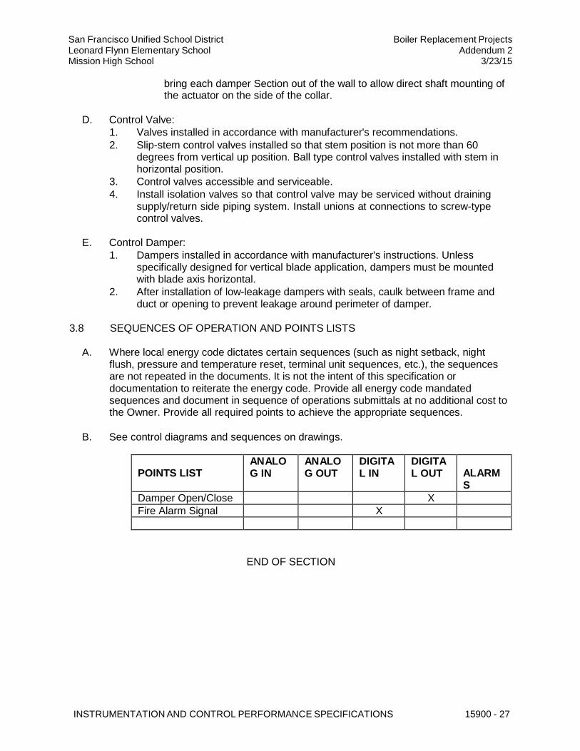
INSTRUMENTATION AND CONTROL PERFORMANCE SPECIFICATIONS 15900 - 27
San Francisco Unified School District Leonard Flynn Elementary School Mission High School
Boiler Replacement Projects Addendum 2
3/23/15
bring each damper Section out of the wall to allow direct shaft mounting of
the actuator on the side of the collar.
D. Control Valve:
1. Valves installed in accordance with manufacturer's recommendations.
2. Slip-stem control valves installed so that stem position is not more than 60 degrees from vertical up position. Ball type control valves installed with stem in horizontal position.
3. Control valves accessible and serviceable.
4. Install isolation valves so that control valve may be serviced without draining supply/return side piping system. Install unions at connections to screw-type control valves.
E. Control Damper:
1. Dampers installed in accordance with manufacturer's instructions. Unless specifically designed for vertical blade application, dampers must be mounted with blade axis horizontal.
2. After installation of low-leakage dampers with seals, caulk between frame and duct or opening to prevent leakage around perimeter of damper.
3.8 SEQUENCES OF OPERATION AND POINTS LISTS
A. Where local energy code dictates certain sequences (such as night setback, night
flush, pressure and temperature reset, terminal unit sequences, etc.), the sequences are not repeated in the documents. It is not the intent of this specification or documentation to reiterate the energy code. Provide all energy code mandated sequences and document in sequence of operations submittals at no additional cost to the Owner. Provide all required points to achieve the appropriate sequences.
B. See control diagrams and sequences on drawings.
POINTS LIST ANALO G IN
ANALO G OUT
DIGITA L IN
DIGITA L OUT
ALARM S
Damper Open/Close X Fire Alarm Signal X
END OF SECTION