Embed Size (px)
Citation preview

Bid# G2010.0186 Jan 11, 2018Addendum 1 Page 1
SAN JOSE/EVERGREEN COMMUNITY COLLEGE DISTRICT
40 South Market StSan Jose, CA 95113
ADDENDUM NO. 1
Request For Bid
SJECCD Bid #G2010.0186
PROJECT NAME: EVC Valle Del Lago Gate Improvement Project
DATE: January 11, 2018
Notice is hereby given that the following revisions, additions and/or deletions are made a part of and incorporated into the Bid Document dated December 11, 2017. This Addendum No. 1 is issued to provide for modifications and clarifications to the Request for Bid documents. Bidder shall ascertain prior to submitting their proposal that they have received all addenda issued and shall acknowledge such receipt in the RFB.
In the event of a conflict between the terms and provisions of this Addendum No. 1 and the terms and provisions of the Request for Bid documents, the terms and provisions of this Addendum No.1 shall control. In all other respects, the Request for Bid documents shall remain unchanged and in full force and effect.
Item #1: Questions and Answers
Question #1: Size of foundation for gate motor?Answer #1: The foundation size shall be 30” W x 30” Lx 30” Deep. Use foundation plate (FAAC-490139-B680H, J-bolts come with the plate) or Equivalent. No reinforcement is required per Manufacturer. The concrete shall be 3,000 psi minimum. Attached for your reference and use is the manual for the gate assembly as well as a Concrete Specification.

Bid# G2010.0186 Jan 11, 2018Addendum 1 Page 2
Question #2: Do subcontractors submit the Construction Careers Agreement (CCA) agreement during the Bid Proposal?Answer #2: No. Subcontractors will submit the CCA(s) within 5 days after the Notice of Intent to Award has been issued.
Question #3: Is the contractor bound to the Project Labor Agreement (PLA) even though the contractor is non-union?Answer #3: This is a prevailing wage job. Please refer to section 00 43 36 (CCA agreement) for further details.
END OF ADDENDUM #1

SAN JOSÈ / EVERGREEN COMMUNITY COLLEGE DISTRICT
Measure G-2010.0186Evergreen Valley College#32307-13– Valle Del Lago Gate Improvements
DOCUMENT 00 31 07BID QUESTION FORM
Version: 02/2015
To: San Jose Evergreen Community College District40 South Market St.San Jose, CA 95113
Attention: Devyani Agate Email : [email protected] Cc: [email protected]
Bid Package #G2010.0186EVC Valle Del Lago Gate Improvements Project
Bid Question
From : Company
Attention:
Date: Re:
Reference Drawing No.
Reference Detail(s) :
Reference Spec. Section
Reference Paragraph(s) :
Question:
Answer:
Answered By:
Firm:
Date:
Question Included in Addendum No. to Bid Package No. By: Date:
Last Date and Time questions can be received is
Date: 01/08/2018 Time:5:00 PM

B680H
FAAC International Inc.West Coast Operations
357 South Acacia AvenueFullerton, CA 92831
FAAC International Inc.Headquarter & East Coast Operations3160 Murrell RoadRockledge, FL 32955Tel. 800 221 8278www.faacusa.com
2
TABLE OF CONTENTS
B680H BARRIER GATE OPERATOR1. TECHNICAL SPECIFICATIONS ............................................................................................................................................................62. ELECTRICAL LAYOUT .........................................................................................................................................................................73. DIMENSIONS .........................................................................................................................................................................................74. INSTALLING THE OPERATOR..............................................................................................................................................................7
4.1 Preliminary checks .......................................................................................................................................................................74.2 Install the foundation plate ..........................................................................................................................................................74.3 Mechanical installation ................................................................................................................................................................74.5 Balancing the Beam ....................................................................................................................................................................12
5. MANUAL OPERATION ........................................................................................................................................................................125.1 Restore normal operations ........................................................................................................................................................12
6. POWER CONNECTION .......................................................................................................................................................................127. FIELD INSTALL LABELS ....................................................................................................................................................................138. REVERSING THE OPENING DIRECTION ..........................................................................................................................................139. MAINTENANCE ...................................................................................................................................................................................13
8.1 Topping up the oil .......................................................................................................................................................................138.2 Air bleeding .................................................................................................................................................................................13
10. INSTALL THE BEAM LIGHTS ...........................................................................................................................................................1411. INSTALL THE COVER .......................................................................................................................................................................1512. SPARE PARTS ...................................................................................................................................................................................16
E680 CONTROL BOARD1. WARNINGS ..........................................................................................................................................................................................182. DESCRIPTION OF THE COMPONENTS ............................................................................................................................................183. TECHNICAL SPECIFICATIONS ..........................................................................................................................................................184. ELECTRICAL CONNECTIONS ............................................................................................................................................................19
4.1 Terminal board J1 (inputs) .........................................................................................................................................................194.2 Terminal board J2 (outputs).......................................................................................................................................................204.3 Terminal board J3 (external flashing lamp) .............................................................................................................................204.4 Terminal board J4 (loop detector) ............................................................................................................................................204.5 Connector J5 (Motor)..................................................................................................................................................................204.6 Connector J7 (Encoder) .............................................................................................................................................................204.7 Connector J10 (Radio) ................................................................................................................................................................204.8 Connector J11 (Beam break-out sensor) .................................................................................................................................204.9 Connector J12 (Emergency battery) .........................................................................................................................................204.10 Connector J13 (36VDC Power Supply) ...................................................................................................................................204.11 Connector J15 (flashing traffic light) ......................................................................................................................................204.12 Connector J16 (beam lights) ....................................................................................................................................................21
5. PROGRAMMING ..................................................................................................................................................................................215.1 Basic configuration .....................................................................................................................................................................215.2 Changing the predefined parameters set ................................................................................................................................225.3 Default Selection Tables ............................................................................................................................................................23
6. Advanced Configuration ....................................................................................................................................................................246.1 Configuring the loop detector ...................................................................................................................................................256.2 Expert Configuration ..................................................................................................................................................................266.3 Pre-Defined Parameter Sets ......................................................................................................................................................296.4 “Expert” default parameters .....................................................................................................................................................30
7. START-UP .............................................................................................................................................................................................307.1 Verifying the diagnostic LEDs ...................................................................................................................................................307.2 Setup .............................................................................................................................................................................................30
8. TESTING THE AUTOMATED SYSTEM ...............................................................................................................................................309. MASTER/SLAVE CONFIGURATION ...................................................................................................................................................3110. INTERLOCK .......................................................................................................................................................................................3211. OPERATING LOGICS TABLE ............................................................................................................................................................33
B680H Rev. A October 2016

3
1. Install the gate operator only when the following conditions have been met:
• The operator is appropriate for the type and usage class of the gate.
• All openings of a horizontal slide gate have been guarded or screened from the bottom of the gate to a minimum of 4 feet (1.25 m) above the ground to prevent a 2.25 inch (55 mm) diameter sphere from passing through openings anywhere in the gate or through that portion of the adjacent fence that the gate covers when in the open position.
• All exposed pinch points are eliminated or guarded.
• Guarding is supplied for exposed rollers.
2. The operator is intended for installation on gates used by vehicles only. Pedestrians must be provided with a separate access opening.
3. To reduce the risk of entrapment when opening and closing, the gate must be installed in a location that allows adequate clearance between the gate and adjacent structures. Swinging gates shall not open outward into public access areas.
4. Before installing the gate operator, ensure that the gate has been properly installed and that it swings freely in both directions. Do not over-tighten the operator clutch or pressure relief valve to compensate for a damaged gate.
5. User controls must be installed at least 6 feet (1.83 m) away from any moving part of the gate and located where the user is prevented from reaching over, under, around or through the gate to operate the controls. Controls located outdoors or those that are easily accessible shall have security features to prevent unauthorized use.
6. The Stop and/or Reset buttons must be located within line-of-sight of the gate. Activation of the reset control shall not cause the operator to start.
7. All warning signs and placards must be installed and easily seen within visible proximity of the gate. A minimum of one warning sign shall be installed on each side of the gate.
8. For gate operators that utilize a non-contact sensor (photo beam or the like):
• See instructions on the placement of non-contact sensors for each type of application.
• Exercise care to reduce the risk of nuisance tripping, such as when a vehicle trips the sensor while the gate is still moving.
• Locate one or more non-contact sensors where the risk of entrapment or obstruction exists, such as at the reachable perimeter of a moving gate or barrier.
• Use only FAAC “Photobeam” photoelectric eyes to comply with UL325.
Important Installation Instructions
WARNING - TO REDUCE THE RISK OF SEVERE INJURY OR DEATH:
• READ AND FOLLOW ALL INSTRUCTIONS.
• Never let children operate or play with the gate controls. Keep remote controls away from children.
• Always keep people and objects away from the gate. NO ONE SHOULD CROSS THE PATH OF A MOVING GATE.
• Test the gate operator monthly. The gate MUST reverse on contact with a rigid object or when an object activates a non-contact sensor. If necessary, adjust the force or the limit of travel and then retest the gate operator. Failure to properly adjust and retest the gate operator can increase the risk of injury or death.
• Use the manual release mechanism only when the gate is not moving.
• KEEP GATE PROPERLY MAINTAINED. Have a qualified service person make repairs to gate hardware.
• The entrance is for vehicles only. Pedestrians must use a separate entrance.
• SAVE THESE INSTRUCTIONS.
IMPORTANT SAFETY INFORMATION
Important Safety Instructions

4
Gate Construction
Vehicular gates should be constructed and installed in accordance with ASTM F2200: Standard Specifica-tion for Automated Vehicular Gate Construction.
For more information, contact ASTM at: www.astm.org
Installation
• If you have any questions or concerns regarding the safety of the gate operating system, do not install the operator and consult the manufacturer.
• The condition of the gate structure itself directly affects the reliability and safety of the gate operator.
• Only qualified personnel should install this equipment. Failure to meet this requirement could cause severe injury and/or death, for which the manufacturer cannot be held responsible.
• The installer must provide a main power switch that meets all applicable safety regulations.
• It is extremely unsafe to compensate for a damaged gate by increasing hydraulic pressure.
• Install devices such as reversing edges and photo beams to provide better protection for personal property and pedestrians. Install reversing devices that are appropriate to the gate design and application.
• Before applying electrical power, ensure that voltage requirements of the equipment correspond to the supply voltage. Refer to the label on your gate operator system.
Usage
• Use this equipment only in the capacity for which it was designed. Any use other than that stated should be considered improper and therefore dangerous.
• The manufacturer cannot be held responsible for damage caused by improper, erroneous or unreasonable use.
• If a gate system component malfunctions, disconnect the main power before attempting to repair it.
• Do not impede the movement of the gate, you may injure yourself or damage the gate system as a result.
• This equipment may reach high thermal temperatures during normal operation, therefore use caution when touching the external housing of the gate operator.
• Use the manual release mechanism according to the procedures presented in this manual.
• Before performing any cleaning or maintenance operations, disconnect power to the equipment.
• All cleaning, maintenance or repair work must performed by qualified personnel.
General Safety Precautions9. For gate operators that utilize a contact sensor (edge
sensor or similar):
• Locate one or more contact sensors where the risk of entrapment or obstruction exists, such as at the leading edge, trailing edge, and post mounted both inside and outside of a vehicular horizontal slide gate
• Locate one or more contact sensors at the bottom edge of a vehicular vertical lift gate.
• Locate one or more contact sensors at the bottom edge of a vertical barrier (arm).
• Locate one or more contact sensors at the pinch point of a vehicular vertical pivot gate.
• Locate hard-wired contact sensors and wiring so that communication between sensor and gate operator is not subjected to mechanical damage.
• Locate wireless contact sensors, such as those that transmit radio frequency (RF) signals, where the transmission of signals are not obstructed or impeded by building structures, natural landscaping or similar hindrances. Wireless contact sensors shall function under their intended end-use conditions.
• Use only FAAC CN60E edge sensor.
Important Installation Instructions (continued)

5
RESIDENTIAL VEHICULAR GATE OPERATOR CLASS I
A vehicular gate operator system intended for use in a single family dwelling, garage or associated parking area.
UL325 Gate Operator Classifications
COMMERCIAL / GENERAL ACCESS VEHICULAR GATE OPERATOR CLASS II
A vehicular gate operator system intended for use in commercial locations or buildings such as multi-family housing units (five or more single family units), hotels, parking garages, retail stores or other buildings that service the general public.
INDUSTRIAL / LIMITED ACCESS VEHICULAR GATE OPERATOR CLASS III
A vehicular gate operator system intended for use in industrial locations or buildings such as factories, loading docks or other locations not intended to service the general public.
RESTRICTED ACCESS VEHICULAR GATE OPERATOR CLASS IV
A vehicular gate operator system intended for use in guarded industrial locations or buildings such as airport security areas or other restricted access locations that do not service the general public, and in which unauthorized access is prevented via supervision by security personnel.

6
N L1
a
b
c
d
e
f
g
hi
j
k
l
m
Fig. 1
Fig. 2
n
o
p
a
b
c
d
e
f
g
h
B680H BARRIER GATE OPERATORThe B680H barrier gate operator system consists of a white aluminium beam with reflectors and optional lights, a steel upright profile and a metal cover. The operator is mounted on the upright profile and it's made with a hydraulic unit and two plunging pistons connected to it, which, by means of a rocker arm, rotate the beam. The beam weight is balanced with a spring fitted on one of the two plunging pistons. The electronic control equipment is also housed on the upright profile, inside a transparent plastic compartment, The whole operator is protected by the external metal cover. The system features an adjustable electronic anti-crushing safety, a device that guarantees stopping and locking of the beam in any position, and a convenient manual release for use in case of power outage or malfunction.
1. TECHNICAL SPECIFICATIONS
Power supply 100-240 Vac / 50-60HzElectric Motor 36Vdc Brushless
Absorbed power 240W
Absorbed current 1.1A at 230 Vac
Motor rotation speed 1000-6000 rpm
Pump capacity 3,2 l/min (max)
Yielded torque 0-273 lbf.ft (0-370 Nm)
Oil type FAAC HP OIL
Oil quantity 1.27 Qt (1.2 Lt)
Anti-crushing System Electronic with absolute encoder
Deceleration type Electronic with absolute encoder
Operating ambient temperature -4 °F +131 °F (-20 °C +55 °C)
Rated Operating Time (ROT) Continuous Duty at 131 °F (55 °C)
Surface protection treatment EP SL LF PRIMER
Beam type Rounded with lights and rubber bumper
Protection Class IP56
Weight (body + cover) 143+44 lb (65+20 Kg)
Opening and closing times including deceleration
1.5 s - 7.5 ft (2.3m) beam 6.0 s - 27 ft (8.3m) beam
a Built-in flashing lampb Electronic control board c Oil filling capd Right piston bleeder screwe Hydraulic unitf Right plunging pistong Built in heatsinkh Right feed tube
i Left feed tubej Release lockk Left plunging pistonl Left piston bleeder screwm Covern Encodero Power Switchp Switching power supply
a Support structureb Mechanical stopsc Rocker armd Drive shaft
e Mounting platef Spring guideg Balance springh Preload adjustment ring nut
Fig. 1 References
Fig. 2 References

7
4
100-240Vac
5
5
23
2
1
Fig. 3
43
1/4
35
1/2
18 1/2
17 1/8
11
3.4
8 in
2.95 in
Fig. 4
4.2
9 in
3.35 in
a
b
20÷2
2m
m
a
7/8
in
b
17.75
25.5
11
18.511.5
3.5
= =
5.4
Fig. 5
Fig. 4
Fig. 6
2. ELECTRICAL LAYOUTFollowing the instructions shown in Fig. 3, prepare the conduits to make all the control board electrical connections with the chosen accessories.Always separate the AC power cables from the control and safety cables (button, receiver, photocells, etc.).
3. DIMENSIONSFor barrier dimensions, refer to Fig. 4. The cover size is the same for both models, while the beam dimensions differ as shown in detail at a (bar S) and b (bar L)
4. INSTALLING THE OPERATOR4.1 Preliminary checks
For the safety and correct operation, make sure that the following conditions are met:• When in motion, the beam must not encounter obstacles or
power cables.• The characteristics of the ground must guarantee sufficient
solidity of the concrete foundation.• No pipes or electrical cables should be present in the foundation
digging area.
• If the barrier body is exposed to vehicle transit, provide for adequate protection against accidental impact, when possible.
• Ensure that there is an availabe and good earth ground connection.
Position the foundation plate so as to allow easy access to the barrier door. The foundation pad must be installed keeping in mind the characteristics of the ground to ensure perfect stability of the operator.
4.2 Install the foundation plate• Assemble the foundation plate as shown in Fig. 5 ref. a• Build a concrete pad as shown in Fig. 5 ref. b• Set the foundation plate as shown in Fig. 5 ref. b providing for
one or more conduits for the passage of the electrical cables.For dimensional reasons, the cable conduits must be placed on one side of the space provided at the base of the barrier (see Fig. 5).
• Use a level to ensure that the plate is perfectly horizontal.• Wait for the concrete to cure.
Dimensions in inches
Dimensions in inches
a B680H Barrier Operatorb Photocellsc Key activation
d Radio receivere Magnetic Loops
4.3 Mechanical installation• Fix the upright profile on the foundation plate using the four
provided nuts (Fig. 6). Remember that the hydraulic unit must usually face the inside of the property, unless a breakway bracket is used. In that case install the barrier so that the breakaway follows the direction of traffic.
8
Fig. 7
a
b
Fig. 8
a
b c
Fig. 9
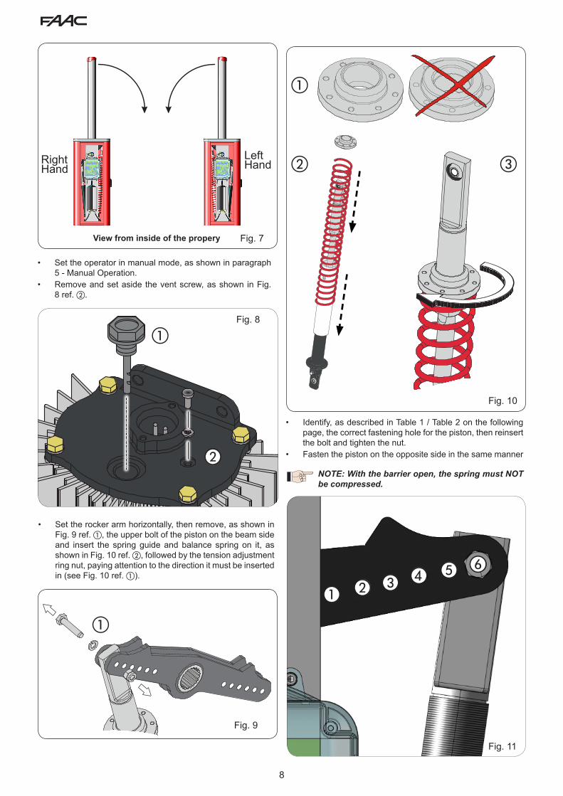
RightHand
View from inside of the propery
LeftHand
a
e
Fig. 10
a b c df
Fig. 11
• Set the rocker arm horizontally, then remove, as shown in Fig. 9 ref. a, the upper bolt of the piston on the beam side and insert the spring guide and balance spring on it, as shown in Fig. 10 ref. b, followed by the tension adjustment ring nut, paying attention to the direction it must be inserted in (see Fig. 10 ref. a).
• Identify, as described in Table 1 / Table 2 on the following page, the correct fastening hole for the piston, then reinsert the bolt and tighten the nut.
• Fasten the piston on the opposite side in the same manner
NOTE: With the barrier open, the spring must NOT be compressed.
• Set the operator in manual mode, as shown in paragraph 5 - Manual Operation.
• Remove and set aside the vent screw, as shown in Fig. 8 ref. b.

9
Beam length
Installed accessories7.5 ft
(2.3 m)9.2 ft
(2.8m)10.8 ft (3.3 m)
12.5 ft(3.8m)
14 ft (4.3m)
14.8 ft(4.5m)
17.4 ft(5.3m)
No accessories 1 2 3 4 4 6 6
Lights 1 2 3 4 4 6 6
Lights / Skirt 1 2 4 5 6 6
Lights / Foot / Skirt 2 3 4 6 6 6
Lights / Foot 2 3 3 5 6 6
Foot 1 2 3 5 6 6
Skirt 1 2 3 4 6 6
Skirt / Foot 2 3 4 5 6 6
Table 1 - S BEAMS
Beam length
Installed accessories17.4 ft(5.3 m)
19 ft(5.8m)
20.5 ft(6.3m)
22.3 ft(6.8m)
23.8 ft(7.3m)
25.5 ft(7.8m)
27 ft(8.3m)
No accessories 2 3 3 4 4 4 5
Lights 2 3 3 4 4 5 6
Lights / Skirt 2 3 4 4 5 6
Lights / Foot / Skirt 3 4 4 5 6
Lights / Foot 2 3 4 4 5 6 6
Foot 2 3 4 4 4 5 6
Skirt 2 3 4 4 5 6
Skirt / Foot 3 3 4 4 5
Table 2 - L BEAMS
The following two tables indicate the fixing position of the pistons on the rocker arm in relation to the length of the beam and the presence of accessories secured to it, if any.
Table 1 refers to the balance spring for “S” beams ( Fig. 4 ref. a ) with lengths equal to or shorter than 17.4 ft (5.3m)Table 2 refers to the balance spring for “L” beams ( Fig. 4 ref. b ) with lengths equal to or longer than 17.4 ft (5. m)
Figure 11 contains the key for identifying the fixing holes based on the number indicated in the tables.

10
ab c
d e
f
g
h
L
c
Fig. 12
• Install the beam bracket and the beam as shown in the sequence in Fig. 12 from a to h using the supplied screws. (the rubber profile of the beam must face down)
NOTE: Do not grease the bolt holding the beam.
11
a
b
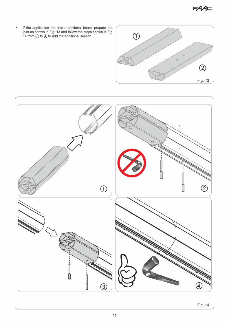
Fig. 13
• If the application requires a sectional beam, prepare the joint as shown in Fig. 13 and follow the steps shown in Fig 14 from a to d to add the additional section
a b
dc
Fig. 14
12
1
2
a b
Fig. 16
Fig. 17
Fig. 15
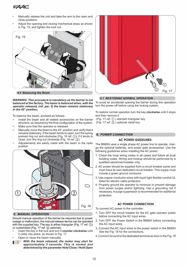
• Manually release the unit and take the arm to the open and close positions
• Adjust the opening and closing mechanical stops as shown in Fig. 15, and tighten the lock nut.
4.4 Balancing the Beam
WARNING: This procedure is mandatory as the barrier is not balanced at the factory. The beam is balanced when, with the operator released, (ref. par. 5) the beam remains stationary in the 45° position.
To balance the beam, proceed as follows:• Install the beam and all related accessories on the barrier
structure, as required by the final configuration of the system.• Make sure that the operator is released.• Manually move the beam to the 45° position and verify that it
remains stationary. If the beam tends to open, turn the spring preload ring nut anti-clockwise (Fig. 16 ref. a); if it tends to close, turn the ring nut clockwise (Fig. 16 ref. b).
• Adjustements are easily made with the beam in the open position
5. MANUAL OPERATIONShould manual operation of the barrier be required due to power outage or malfunction, the manual release device can be operated with the supplied key. The key is either triangular (Fig. 17 ref. a) or customised (Fig. 17 ref. b optional).• Insert the key in the lock and turn it counter clockwise until
it clicks into place, as shown in Fig. 17• Open or close the beam manually.
With the beam released, the motor may start for approximately 3 seconds. This is normal and determined by the parameter Hold Close / Hold Open
6. POWER CONNECTION
AC POWER GUIDELINES:The B680H uses a single phase AC power line to operate, char-ge the optional batteries, and power gate accessories. Use the following guidelines when installing the AC power:1. Check the local wiring codes in all cases and follow all local
building codes. Wiring and hookup should be performed by a qualified electrician/installer only.
2. AC power should be supplied from a circuit breaker panel and must have its own dedicated circuit breaker. This supply must include a green ground conductor.
3. Use copper conductor wires with liquid tight flexible conduit UL listed for electric cable protection
4. Properly ground the operator to minimize or prevent damage from power surges and/or lightning. Use a grounding rod if necessary. A surge suppressor is recommended for additional protection.
AC POWER CONNECTIONTo connect AC power to the controller:1. Turn OFF the circuit breaker for the AC gate operator power
before connecting the AC input wires.2. Turn OFF the Power Switch in the B680H before connecting
the AC input wires.3. Connect the AC input wires to the power switch in the B680H
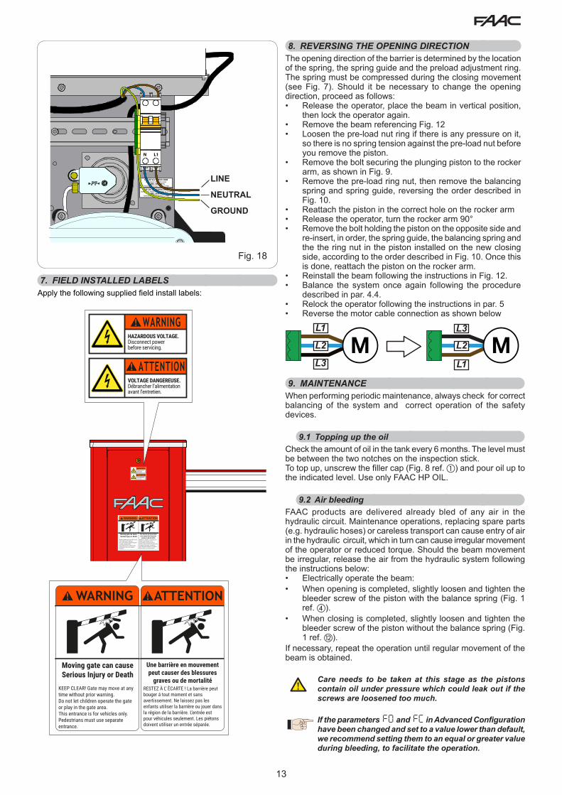
See the Fig. 18 for the connections.4. Connect Ground to the dedicated terminal as shon in the Fig. 18
5.1 RESTORING NORMAL OPERATIONTo avoid an accidental opening the barrier during this operation turn the power off before using the locking system.
To restore normal operation turn the key clockwise until it stops and then remove it (Fig. 17 ref. a ) standart triangular key (Fig. 17 ref. b ) optional metal key
13
Fig. 18
100-240 Vac 50/60Hz 280WUse copper conductor wires
14 AWG, 600V, 80°CTerminal Block max Torque 0.6 Nm
100-240 Vac 50/60Hz 280WUtilisez des câbles conducteurs en cuivre
14 AWG, 600V, 80°CTerminal Block Couple Max 0.6 Nm
N L1
7. FIELD INSTALLED LABELSApply the following supplied field install labels:
HAZARDOUS VOLTAGE. Disconnect power before servicing.
WARNING
VOLTAGE DANGEREUSE. Débrancher l’alimentationavant l’entretien.
ATTENTION
HAZARDOUS VOLTAGE. Disconnect power before servicing.
WARNING
VOLTAGE DANGEREUSE. Débrancher l’alimentationavant l’entretien.
ATTENTION
WARNING
Moving gate can causeSerious Injury or Death
KEEP CLEAR! Gate may move at any time without prior warning.Do not let children operate the gate or play in the gate area.This entrance is for vehicles only.Pedestrians must use separate entrance.
ATTENTION
Une barrière en mouvement peut causer des blessures
graves ou de mortalitéRESTEZ À L’ ÈCARTE ! La barrière peut bouger á tout moment et sans avertissement. Ne laissez pas les enfants utiliser la barrière ou jouer dans la région de la barrière. L’entrée est pour véhicules seulement. Les piétons doivent utiliser un entrée séparée.
8. REVERSING THE OPENING DIRECTIONThe opening direction of the barrier is determined by the location of the spring, the spring guide and the preload adjustment ring. The spring must be compressed during the closing movement (see Fig. 7). Should it be necessary to change the opening direction, proceed as follows:• Release the operator, place the beam in vertical position,
then lock the operator again.• Remove the beam referencing Fig. 12• Loosen the pre-load nut ring if there is any pressure on it,
so there is no spring tension against the pre-load nut before you remove the piston.
• Remove the bolt securing the plunging piston to the rocker arm, as shown in Fig. 9.
• Remove the pre-load ring nut, then remove the balancing spring and spring guide, reversing the order described in Fig. 10.
• Reattach the piston in the correct hole on the rocker arm• Release the operator, turn the rocker arm 90° • Remove the bolt holding the piston on the opposite side and
re-insert, in order, the spring guide, the balancing spring and the the ring nut in the piston installed on the new closing side, according to the order described in Fig. 10. Once this is done, reattach the piston on the rocker arm.
• Reinstall the beam following the instructions in Fig. 12.• Balance the system once again following the procedure
described in par. 4.4.• Relock the operator following the instructions in par. 5• Reverse the motor cable connection as shown below
M ML1
L2
L3 L1
L2
L3
9. MAINTENANCEWhen performing periodic maintenance, always check for correct balancing of the system and correct operation of the safety devices.
9.1 Topping up the oilCheck the amount of oil in the tank every 6 months. The level must be between the two notches on the inspection stick.To top up, unscrew the filler cap (Fig. 8 ref. a) and pour oil up to the indicated level. Use only FAAC HP OIL.
9.2 Air bleedingFAAC products are delivered already bled of any air in the hydraulic circuit. Maintenance operations, replacing spare parts (e.g. hydraulic hoses) or careless transport can cause entry of air in the hydraulic circuit, which in turn can cause irregular movement of the operator or reduced torque. Should the beam movement be irregular, release the air from the hydraulic system following the instructions below:• Electrically operate the beam:• When opening is completed, slightly loosen and tighten the
bleeder screw of the piston with the balance spring (Fig. 1 ref. d).
• When closing is completed, slightly loosen and tighten the bleeder screw of the piston without the balance spring (Fig. 1 ref. l).
If necessary, repeat the operation until regular movement of the beam is obtained.
Care needs to be taken at this stage as the pistons contain oil under pressure which could leak out if the screws are loosened too much.
If the parameters FO and FC in Advanced Configuration have been changed and set to a value lower than default, we recommend setting them to an equal or greater value during bleeding, to facilitate the operation.
LINE
NEUTRAL
GROUND

14
a b
c
d e
Fig. 19
10. INSTALL THE BEAM LIGHTS
Installation of an LED bar light kit increases visibility of the bar.Proceed to install following the instructions contained in Fig. 19 and securing the connection cable according to the path shown, using the holes to secure it with tie-wraps.Connect the kit to J16 on the electronic board and configure it according to the available modes (refer to Par 4.12 in the control board section)
NOTE: Make sure the two connector make good contact with the conductors inside the cord. Should the bar lights still not turn on, reverse the connection polarity.

15
a
b
Fig. 20
d
e
f
c
11. INSTALL THE COVER
To install the protective cover on the operator follow the steps shown in Fig. 20.

16
1
1
2
3
3
4
5
56
7
8
8
10
11
12
12
13
1314
15
16
17
18
19
19
20
20
9
9
2021
OIL
Part Part Number Description01 63000108 Bearing02 63000118 Splined Shaft Kit03 63000137 Lever Bearing Spacer04 63000132 Rocker Arm05 63000131 Positive Stops06 63000138 Encoder Magnetic Sensor07 63000111 Encoder08 63000109 Fork With Ball Joint Group09 63000133 Cylinder10 63000129 Hydraulic Unit11 63000113 Female Connector Kit12 7110115 Eye Bolt13 63000112 Hydraulic Hoses14 63000117 Manual Release Group15 63000128 Electronic Control Board16 - Power Switch17 63000119 B680 Power Supply Group18 63000139 E680 Control Board Box Cover
12. SPARE PARTS

17
1097642 831
116
3
65
Part Part Number Description01 63000162 Distribution Flange Group02 7090010015 O-ring 4.48 X 1.78 03 63000154 Hydraulic Unit Gasket04 63000696 1,5 L/Min Pump05 703101 Lock Washer06 63000123 Motor/Pump Interface Flange07 63000122 Brushless Motor Group08 63000159 Hydraulic Tank09 63000124 Tank Cover10 7112065 Oil Level Plug With Level Indicator11 63000158 Hydraulic Unit Tie Rod

18
J6
J12
J5
J11 J14
J7
+ - F
SW1 SW2 SW3J15
J1 J2 J3 J4
M2 M1A
M1
DL1 DL2
DL1
0
DL1
1
DL1
2
DL1
3
DL1
4
DL1
8
DL1
7
DL5
DL6
DL9
DL3
DL4
DL15
2Eas
y BU
S
OPE
NCLO
SE
FSW
STO
PEM
R
GN
D
+24
3 4 5 6 7 8 9 10 11 12 13 14 1516 17 18 19 20 21 22 23 2 2
+24
+24
+24
+24
OU
T1
OU
T2
OU
T3
Rela
y N
O
GN
D
LAM
P
LOO
P 1
LOO
P 2
MOTOR
POWER
BATTERY
ENCODERDISP1
DL7
DL8
DL1
6M
SW4
1 2 2 24 5 6 7
Rela
y N
ORe
lay
CO
M
J13
J16
SW5
J10
OUT5OUT6
Fig. 21
a
E680 CONTROL BOARD
DISP1 Signalling/Programming display
DL1 BUS Device status
DL2 BUS status (see paragraph 5.3)
DL3 LOOP 1 status
DL4 LOOP 2 status
DL5 Board failure signal
DL6 Not used
DL7 Encoder status
DL8 Not used
DL9 Board power supply present
DL10 OPEN input status LED
DL11 CLOSE input status LED
DL12 FSW input status LED
DL13 STOP input status LED
DL14 EMR input status LED
DL15 Released bar signal
DL16 Battery power signal
DL17 Radio channel 1 activity
DL18 Radio channel 2 activity
J1 Input signal connector
J2 Digital output connector
J3 Signalling lamp connector
J4 Detection loop connector
J5 Motor connector
J6 BUS 2Easy connector
J7 Beam movement encoder connector
J10 Connector for radio board
J11 Released bar detection connector
J12 Emergency battery connector
J13 Continuous power voltage connector
J14 USB connector for firmware upgrade
J15 Integrated flashing traffic light connector
J16 Beam Lights Connector
SW1 Programming key “F”
SW2 Programming key “+”
SW3 Programming key “-”
SW4 /SW5 LOOP 1 / LOOP 2 calibration button
M1/M1A/M2 Optional module connector (Connectivity):
1. WARNINGSWarning - Before carrying out any work on the control board (connections, maintenance, etc.) always:• cut off the electrical power;• install a differential magnetothermic switch with a suitable
activation threshold upstream from the system;• always separate the power cables from the control and safety
cables (button, receiver, photocells, etc.);• avoid any electrical disturbance using separate sheaths or a
shielded cable (with the shield connected to the earth).
2. DESCRIPTION OF THE COMPONENTS
Mains power voltage
100-240 V~ +6% -10%connected to switching power supply
Continuous power voltage
36 V "
Absorbed power 240WAccessories power supply
24 V "
Max accessories current
800 mA
Operating ambient temperature
-4 °F +131 °F (-20 °C +55 °C)
Protection fuses 4 self-restoringPause time Programmable
(from 0 seconds to 4.1 minutes)
3. TECHNICAL SPECIFICATIONS
Work time Programmable (from 0 to 4 minutes)Motor power Programmable on 50 levelsMotor speed Programmable on 10 levelsProgrammability 3 configuration levels for greater flexibility
of useRapid connector 1 5-pin connector for radio boardProgrammable outputs
4 programmable outputs in 19 different functions
Specifications Deceleration management, encoder, multi-function display, BUS technologyand built-in loop detectors

19
2Easy
OPE
NCLO
SE
FSW
STO
PALA
RM
GND +24
1 2 3 4 5 6 7 8 9 10 11 12 13 14 1516 17 18 19 20 21 22 23 24 25 26 27+
24
+24
+24
+24
OU
T1
OU
T2
OU
T3
GN
D LAMP
LOOP
BUS
LOOP 1 LOOP 2
Encoder
Relais
NO CO
M
1 2
OUT4
OUT5
OUT6
GND
Fig. 22
J1
+24
+24
GND
OPE
NCLO
SE
FSW
STO
PALA
RM
GND +24
3 4 5 6 7 8 9 10 11
SAFE
TX CLRX CL
1
2
5
4
3
1
2
12 13 14 1516 17 18 19 20 21
+24
+24
+24
+24
OU
T1
OU
T2
OU
T3
GN
D
Relais
NO
CO
M
J2
Fig. 23
4. ELECTRICAL CONNECTIONS
To connect the photocells and safety
devices, refer to paragraph 4.1.1
Released beam
Integrated flashing
traffic light
4.1 Terminal board J1 (inputs)OPEN - Open” command (N.O. - terminal 3): means any pulse generator (e.g. button) which, by closing a contact, commands opening and/or closing of the barrier.CLOSE - Close” command (N.O. - terminal 4): means any pulse generator (e.g. button) which, by closing a contact, commands closing of the barrier.FSW - Safety contact when closing (N.C. - terminal 5): the purpose of the closing safeties is to protect the area affected by the movement of the barrier during the closing phase, reversing its motion. They never trip during the opening cycle.The closing Safeties, if engaged when the automated system is open, prevent the closing movement.
If CLOSE safety devices are not connected, jumper terminals FSW and GND (Fig. 26) and leave the FAILSAFE function (parameter o1 in Advanced Configuration) set on the default value (disabled)
STP - STOP contact (N.C. - terminal 6): means any device (e.g. button) which, by opening a contact, can stop movement of the automated system.
If STOP safety devices are not connected, jumper terminals STOP and GND (Fig. 26)
EMR - Emergency contact (N.C. - terminal 7): means any device (e.g. switch) which, if activated in a situation of emergency, will open the barrier until the contact is restored. When activated, this input has priority over any other command.
If emergency safety devices are not connected, jumper terminals ALM and GND (Fig. 26)
GND (terminals 8-9) - Accessories power supply minus+24 (terminals 10-11) - Accessories power supply plus
The maximum load of the accessories is 800mA. To calculate absorption, refer to the instructions included with the individual accessories.
4.1.1 Connecting the safety devicesThe E680 control board features an input for closing safety devices, which trip during closing of the automated system, provided to protect the gate area from the risk of impact.These devices must use a signal with “N.C.” contact, and must be connected in series to the relay photocells that may be installed on the system, as shown in Fig. 23 to Fig. 26.
Fig. 23: connection of one pair of closing photocells, with FAILSAFE safety enabled: in addition to making the connection as shown in the diagram, it is necessary to set in Advanced Configuration o1 = 00 Fig. 24: connection of one pair of closing photocells without
FAILSAFE safety Fig.25: connection of two pairs of closing photocells without
FAILSAFE safetyFig. 26: connection of no safety device
20
J1
+24
GND
+24
GND
OPE
NCLO
SE
FSW
STO
PALA
RM
GND +24
3 4 5 6 7 8 9 10 11
SAFE
TX CLRX CL
1
2
5
4
3
1
2
Fig. 24
Fig. 25
J1
+24
GND
+24
GND
OPE
NCLO
SE
FSW
STO
PALA
RM
GND +24
3 4 5 6 7 8 9 10 11
SAFE
TX CLRX CL
1
2
5
4
3
1
2
TX CL RX CL
1
2
5
4
3
1
2
+24
GND
+24
GND
Fig. 26
J1
OPEN
CLO
SE
FSW
STO
PALA
RM
GND +24
3 4 5 6 7 8 9 10 11
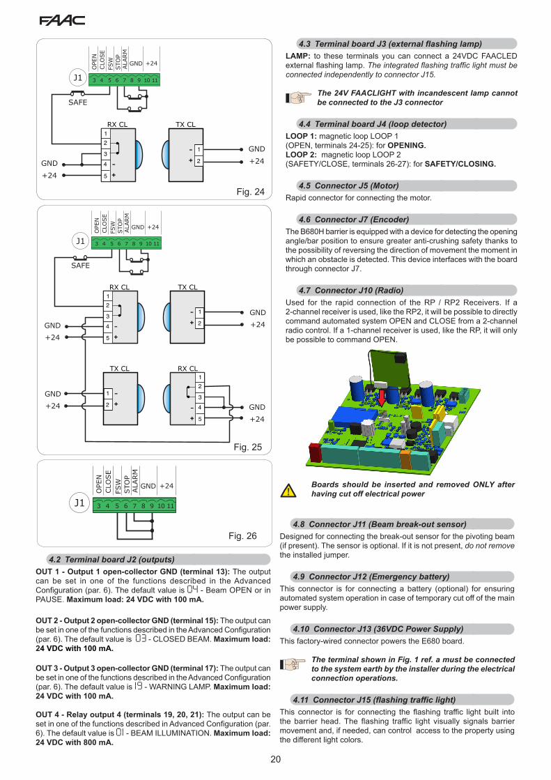
4.2 Terminal board J2 (outputs)OUT 1 - Output 1 open-collector GND (terminal 13): The output can be set in one of the functions described in the Advanced Configuration (par. 6). The default value is 04 - Beam OPEN or in PAUSE. Maximum load: 24 VDC with 100 mA.
OUT 2 - Output 2 open-collector GND (terminal 15): The output can be set in one of the functions described in the Advanced Configuration (par. 6). The default value is 03 - CLOSED BEAM. Maximum load: 24 VDC with 100 mA.
OUT 3 - Output 3 open-collector GND (terminal 17): The output can be set in one of the functions described in the Advanced Configuration (par. 6). The default value is 19 - WARNING LAMP. Maximum load: 24 VDC with 100 mA.
OUT 4 - Relay output 4 (terminals 19, 20, 21): The output can be set in one of the functions described in Advanced Configuration (par. 6). The default value is 01 - BEAM ILLUMINATION. Maximum load: 24 VDC with 800 mA.
Boards should be inserted and removed ONLY after having cut off electrical power
4.3 Terminal board J3 (external flashing lamp)LAMP: to these terminals you can connect a 24VDC FAACLED external flashing lamp. The integrated flashing traffic light must be connected independently to connector J15.
The 24V FAACLIGHT with incandescent lamp cannot be connected to the J3 connector
4.4 Terminal board J4 (loop detector)LOOP 1: magnetic loop LOOP 1 (OPEN, terminals 24-25): for OPENING.LOOP 2: magnetic loop LOOP 2 (SAFETY/CLOSE, terminals 26-27): for SAFETY/CLOSING.
4.5 Connector J5 (Motor)Rapid connector for connecting the motor.
4.6 Connector J7 (Encoder)The B680H barrier is equipped with a device for detecting the opening angle/bar position to ensure greater anti-crushing safety thanks to the possibility of reversing the direction of movement the moment in which an obstacle is detected. This device interfaces with the board through connector J7.
4.7 Connector J10 (Radio)Used for the rapid connection of the RP / RP2 Receivers. If a 2-channel receiver is used, like the RP2, it will be possible to directly command automated system OPEN and CLOSE from a 2-channel radio control. If a 1-channel receiver is used, like the RP, it will only be possible to command OPEN.
4.8 Connector J11 (Beam break-out sensor)Designed for connecting the break-out sensor for the pivoting beam(if present). The sensor is optional. If it is not present, do not removethe installed jumper.
4.9 Connector J12 (Emergency battery)This connector is for connecting a battery (optional) for ensuring automated system operation in case of temporary cut off of the main power supply.
4.10 Connector J13 (36VDC Power Supply)This factory-wired connector powers the E680 board.
The terminal shown in Fig. 1 ref. a must be connected to the system earth by the installer during the electrical connection operations.
4.11 Connector J15 (flashing traffic light)This connector is for connecting the flashing traffic light built into the barrier head. The flashing traffic light visually signals barrier movement and, if needed, can control access to the property using the different light colors.

21
4.12 Connector J16 (beam lights)Connector which allows the rope light for the rod to be connected, providing visual warning of barrier movement. The connector has a common GND connection and two +36V (BLR / BRG) outputs. The default value is 02 - “BEAM LIGHTING TYPE 2” for OUT 5, 04 - “BEAM OPEN OR PAUSED” for OUT 6.
5. PROGRAMMINGThe E680 board features 3 programming levels that make it entirely configurable and allow it to adapt the logics to any use.Each of the three levels can be accessed through a specific key combination.
Changes to the configuration parameters become effective immediately, while final storage occurs only upon exiting configuration and returning to the automated system status display. If the equipment is powered down before returning to the automated system status display, all changes made will be lost.
5.1 Basic configurationTo perform BASIC programming:1. Press and hold button F; the name of the first function is
displayed.2. Release the button; the function value is displayed and can be
modified using the + and - buttons.3. Press and hold F again; the name of the following function is
displayed, and so on.The last function St lets you choose whether to save the configuration made (Y) or exit without saving (no). Later, the display will resume showing the automated system status
You can go to St at any time. To exit programming, press F and then -.
BASIC CONFIGURATION
Display Function Default
cF Barrier configuration
01 Minimum mass
06 Maximum mass
Before starting the operator, you must set the correct value, directly correlated to the length of the beam and the number and type of accessories installed. To determine the value, refer to Tables 3 and 4.
WARNING: Setting a mass default lower than the one actually installed could cause irreversible damage to the bar and barrier structure.Loading a different configuration will reset the parameters to the default values
06
dF DefaultY indicates that all values set correspond
to the defaults
no indicates that one or more set values are different from the defaults. Select Y to restore the default configuration.
Y
Ct Master / slave configurationMA Configures the board in master mode
SL Configures the board in slave mode
For details on MASTER / SLAVE configuration, refer to section 9.
MA
Display Function Default
bu BUS accessories menu
For functions associated with this parameter see paragraph 5.3
no
LO Operating logics
A Automatic
A1 Automatic 1
E Semi-automatic
P Parking
PA Parking automatic
Cn Condo
CA Condo automatic
C Dead-man
CU Custom
E
PA Pause timeIs effective only if an automatic logic is chosen; the value can be set from O to 59 sec. in one second steps. Next, the display changes to minutes and tens of a second (separated by a decimal point) and time is adjusted in 10-second steps up to the maximum value of 4.1 minutes.e.g. if the display shows 2.5, the pause time will be 2 minutes and 50 seconds.
20
So Opening speedAdjusts the barrier opening speed.
00 Minimum speed
10 Maximum speed
NOTE: The actual maximum speed is de-pendent on the “mass” value programmed in Barrier Configuration
10
Sc Closing speedAdjusts the barrier closing speed.
00 Minimum speed
10 Maximum speed
NOTE: The actual maximum speed is de-pendent on the “mass” value programmed in Barrier Configuration
02
L1 Loop 1Activating this parameter, any loop that is connected to the Loop 1 input will serve as an OPEN function.
Y Loop 1 enabledno Loop 1 disabled
NOTE: Should this function be disabled, the detection status of the loop will in any case remain available on one of the two outputs, if configured (see parameters o1 ... o4 in Advanced Configuration)
no

22
Display Function Default
L2 Loop 2Activating this parameter, any loop that is connected to the Loop 2 input will serve as a SAFETY/CLOSE function.
Y Loop 2 enabledno Loop 2 disabled
(see note regarding Loop 1)
no
S1 Loop 1 sensitivityAdjusts the sensitivity of the vehicle detection loop
00 Minimum sensitivity10 Maximum sensitivity
05
S2 Loop 2 sensitivityAdjusts the sensitivity of the vehicle detection loop
00 Minimum sensitivity10 Maximum sensitivity
05
Mt Motor movement
Using the function provided by this para-meter makes it possible to manually move the barrier bar, operating as dead-man. Pressing + will open the automated system, pressing - causes the automated system to close.
oP pressing +, open
cL pressing -, close
--
tL LearningWorking time and limit switch learning (see section 7.2)
--
St SYSTEM STATUS:This allows you to choose whether to save the program-med data upon quitting. Y = quit and save the data no = quit without saving the data After quitting the program, press the F key to display the status of the automated system
00 Beam closed
01 Beam open
02 Stationary ready to open
03 Stationary ready to close
04 Automated system paused
05 Opening
06 Closing
07 Failsafe in progress
08 2-EASY device verification in progress
09 Pre-flashing then OPENS
10 Pre-flashing then CLOSES
11 EMERGENCY Open
You can go to St at any time by pressing F and then -.
Displaying of the automated system status St is extremely important for the installing/maintenance technician in order to distinguish the logical processes that the board carries out during movement.
If, for example, the automated system status is CLOSED, the display MUST read 00. When the OPEN command is
received, the display will change to 09, if pre-flashing is enabled, or directly to 05 (the OPENING movement) to then display 01 once the position of gate OPEN is reached).
Example of a status sequence displayed starting from a closed barrierThe sequence does not include statuses 09 and 10 which correspond to pre-flashing when opening and closing, respectively.
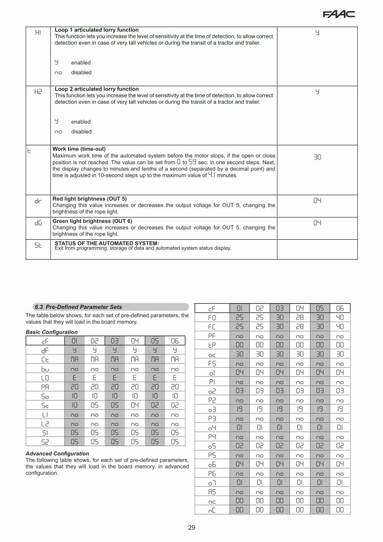
5.2 Changing the predefined parameters setThe E680 board features six sets of pre-defined configurations that allow rapid adapting to the size of the beam installed. To select one of the available configurations change the parameter cF from the default value of 06 to that corresponding to the barrier configuration (beam length, type and quantity of accessories installed) given in Table 3 or Table 4 on the next page (for example, choose the default 04 for a beam type “L” of 17.4 ft (5.3 m) with lights).
To complete the configuration, it is necessary to exit the Basic Configuration menu by pressing “F” until parameter St is reached or by pressing “F” and “-”
This operation changes the value of the parameters So and SC in Basic configuration and FO, FC, oc in Advanced configuration, setting them on the default values as shown in the tables in paragraph 6.3.
Setting a set of pre-defined parameters that does not correspond to the actual configuration of the barrier could cause irreversible damage to the automated system, in particular if the default corresponds to a beam length shorter than the actual one.
00 Beam closed 05 Opening
01 Beam open /04 Pause 06 Closing

23
Beam length
Installed accessories7.5 ft
(2.3 m)9.2 ft
(2.8m)10.8 ft (3.3 m)
12.5 ft(3.8m)
14 ft (4.3m)
14.8 ft(4.5m)
17.4 ft(5.3m)
No accessories 1 1 2 2 2 3 3
Lights 1 1 2 2 2 3 3
Lights / Skirt 1 1 2 3 3 3
Lights / Foot / Skirt 1 2 2 3 3 3
Lights / Foot 1 2 2 3 3 3
Foot 1 1 2 3 3 3
Skirt 1 1 2 2 3 3
Skirt/Foot 1 2 2 3 3 3
Table 3 - S BEAMS
Beam length
Installed accessories17.4 ft(5.3 m)
19 ft(5.8m)
20.5 ft(6.3m)
22.3 ft(6.8m)
23.8 ft(7.3m)
25.5 ft(7.8m)
27 ft(8.3m)
No accessories 4 5 5 5 5 5 6
Lights 4 5 5 5 5 6 6
Lights / Skirt 4 5 6 6 6 6
Lights / Foot / Skirt 5 5 5 6 6
Lights / Foot 4 5 5 5 6 6 6
Foot 4 5 5 5 5 6 6
Skirt 4 5 5 5 6 6
Skirt/Foot 5 5 5 5 6
Table 4 - L BEAMS
5.3. DEFAULT SELECTION TABLES (cF parameter)The purpose of the two following tables is to determine, depending on the length of the bar and the number and type of accessories installed, the correct default value to set in the first Basic programming function.
Table 3 refers to the balance spring for “S” beams ( Fig. 4 ref. a ) with lengths equal to or shorter than 17.4 ft (5.3m)Table 4 refers to the balance spring for “L” beams ( Fig. 4 ref. b ) with lengths equal to or longer than 17.4 ft (5. m)

24
6. Advanced Configuration
To access Advanced Configuration, press F and, while holding it, also press +:• when + is released, the number of the first available function
will appear• when F is also released, the value is displayed, and can be
changed using + and -• pressing F again, and holding it, the name of the next parameter
will be displayed; when released, the value can be changed using + and -
• once the last function has been reached, pressing F makes it possible to either save the previously changed parameters or exit without saving the changes; the display will go back to showing the status of the inputs.
ADVANCED CONFIGURATION
Display Function Default
FO Opening motor forceAdjusts the thrust of the motor during the ope-ning phase.
00 Minimum power
50 Maximum power
40
FC Closing motor forceAdjusts the thrust of the motor during the closing phase.
00 Minimum power
50 Maximum power
40
PF Pre-flashingThis parameter is used to activate the flashing lamp for 5 seconds before the selected movement.
no disabledOC before each movementCL before each closing movement
OP before each opening movement
PA only at the end of the pause
no
tP Pre-flashing timePre-flashing time expressed in seconds.
00 minimum pre-flashing
10 maximum pre-flashing
00
Display Function Default
oc Sensitivity of obstacle during closing This determines the sensitivity to an obstacle before reversing takes place.
01 Minimum sensitivity
50 Maximum sensitivity
30
o1 Output 1Setting this function makes it possible to modify the signal type of output 1, allowing high connection flexibility with external devices.
00 Failsafe0 1 TYPE 1 BEAM ILLUMINATION
(output active when beam closed, disabled with bar open or paused, intermittent when moving). Use only with output 4!
02 BAR LIGHTING TYPE 2 (flashing output during opening, closing and with rod closed or stopped. inactive with rod open or paused).
03 Beam CLOSED04 Beam OPEN or in PAUSE, it goes off
during closing pre-flashing.05 Beam in OPENING MOVEMENT,
including pre-flashing.06 Beam in CLOSING MOVEMENT,
including pre-flashing.07 Beam STATIONARY08 Beam in EMERGENCY mode09 LOOP1 engaged10 LOOP2 engaged11 OPEN for E680 slave12 CLOSE for E680 slave13 Beam RELEASED14 Not used15 Not used16 FCA engaged17 FCC engaged18 Interlock19 WARNING LAMP (on during opening
and pause, flashing when closing, off when the automated system is closed)
20 Battery operation
04
P1 Output 1 PolarityAllows setting of the output polarity:
Y output NCno output NO
NOTE: if the output setting is 00 (Failsafe), keep the value set to no
no
o2 Output 2Output 2 signal type, see “Output 1” 03

25
Display Function Default
P2 Output 2 PolarityOutput 2 polarity, see parameter regarding “Output 1 Polarity”
no
o3 Output 3Output 3 signal type, see “Output 1” 19
P3 Output 3 PolarityOutput 3 polarity, see parameter regarding “Output 1 Polarity”
no
o4 Output 4Output 4 signal type, see “Output 1” 01
P4 Output 4 PolarityOutput 4 polarity, see parameter regarding “Output 1 Polarity”
no
o5 Output 5Output 5 signal type, see “Output 1”
02
P5 Output 5 polarityOutput 5 polarity, see parameter for “Output 1 polarity”
no
o6 Output 6Output 6 signal type, see “Output 1” 04
P6 Output 6 polarityOutput 6 polarity, see parameter for “Output 1 polarity”
no
o7 Integrated flashing lamp operating modeLets you choose between two operating modes for the integrated flashing lamp (if present) connected to output J15.
01 “Traffic light” mode (steady green when paused/open, flashing red when moving, steady red when closed)
02 ”Flashing lamp” mode (flashing red when bar is moving, off in all other cases)
01
AS Service request (linked to the following two functions):If activated, at the end of the countdown (which can be set with the two following “Cycle Programming” functions) it activates the LAMP output for 4 sec every 30 sec (service request). It can be useful for setting programmed maintenance work.
Y Activeno Disabled
no
nc Cycle programming in thousands:Is used to set a countdown of the system operation cycles; the value can be set from 0 to 99 (thousands of cycles). The value displayed is updated with the succession of the cycles, interacting with the value of n C (99 decrements of n c correspond to 1 decrement of n C ).The function can be used, together with n C , to verify the use of the system and for use of “Service Request”.
00
Display Function Default
nC Cycle programming in hundreds of thousands:Is used to set a countdown of the system operation cycles; the value can be set from 0 to 99 (hundreds of thousands of cycles). The value displayed is updated with the succession of the cycles, interacting with the value of n c . (1 decrement of n C corresponds to 99 decrements of n c ).The function can be used, together with n c , to verify the use of the system and for use of “Service Request”.
01
St SYSTEM STATUS:This allows you to choose whether to quit the program and save the data. Y = quit and save the data no = quit without saving the dataOn quitting the program, press the F key to display again
the status of the automated system.You can go to St at any time by pressing F and then-
6.1 Configuring the loop detectorThe E680 board features an integrated metal mass detector for the induction detection of vehicles.
6.1.1 Specifications:• Galvanic separation between the detector electronics and the
loop electronics• Automatic alignment of the system immediately following
activation• Continuous resetting of the frequency drifts• Sensitivity independent of loop inductivity• Adjustment of the loop work frequency with automatic selection• Occupied loop message with LED display• Loop status addressable on outputs
6.1.2 Connection:Connect the loops according to the layout on page 7, Fig. 2
- Terminals 24 - 25 for LOOP 1 = loop with gate opening function;- Terminals 26 - 27 for LOOP 2 = loop with closing and/or safety
when closing function.For more information on the effect of the loop signals on the automated system, refer to the logics tables in paragraph 10 “OPERATING LOGICS TABLE”.To enable the functionality of the connected loops, enter Basic configuration mode and set parameters L1 and L2 on Y consistent with the number and type of connected loops. If only one loop is installed, enable only the corresponding programming step.The loop detector operating status is indicated by the DL3 and DL4 status LEDs.

26
3/8”
1-1/
2” to
2“
~ 3 ft
6.1.3 CalibrationEach time the E680 board is powered, the integrated loop detector performs a calibration of the connected loops. Therefore, you can perform calibration by cutting off power to the board for at least 10 seconds and then reconnecting it.From the barrier status display, you can press, at any time, SW4/CAL1 to calibrate the loop connected to the LOOP 1 input or SW5/CAL2 to calibrate the loop connected to the LOOP2 input.
Calibration is highlighted by the board diagnostics by flashing LEDs DL3 and DL4, and when calibration is completed, they will indicate the loop detection status, if connected.The other signals provided by the board diagnostics are described in the following table:
DL3
DL4
LOO
P 1
LOO
P 2
2 22 24 5 6 7
If one or both magnetic loops are not installed, the loop detector, following a first attempt to calibrate, will keep the status LEDs flashing every 5 seconds (as shown in the above table)
LED Status LOOP StatusOff Loop clearOn Loop engagedFlashing (0.5 s) Loop calibration
in progressRapid flashing Loop short circuitSlow flashing(5 s)
No loop or loop interrupted
Two flashes (every 5 s) Non-conforming loop (resistance or induc-tance values out of range)
6.1.4 Adjusting sensitivityBy adjusting the sensitivity of the loop detector, you determine the variation of inductivity, for each channel, that a vehicle must cause in order to activate the corresponding detector output.Sensitivity is adjusted separately for each channel using the two parameters S1 and S2 in Basic configuration
6.1.5 Making the loopsThe loop must be laid at least 6” (15cm) from fixed metal objects, at least 20” (50cm) from moving metal objects and no more than 2” (5cm) from the surface of the final paving.Use a standard AWG 16 unipolar cable (direct buried cable must have double insulation). Make a preferably square or rectangular loop by preparing a PVC cable duct or by tracing the paving, as shown in figure 16 (the corners must be cut at a 45° angle to avoid cable breaks). Lay the cable using the number of windings shown in the table. The two ends of the cable must be twisted together (at least 6 times per foot) from the loop to the E680 board. Avoid splicing a cable (if necessary, solder the conductors and seal the splice using a heat-shrinking sheath) and keep it separate from the mains power lines.
Loop Perimeter
Nr. of Windings
less than 10 ft 6from 10 to 13 ft 5from 13 to 20 ft 4from 20 to 40 ft 3more than 40 ft 2
6.2 Expert ConfigurationWit the EXPERT configuration the operating logics previously programmed with Basic and Advanced configuration can be further customized.
Before making changes at this level, be certain that the steps you wish to change and their effect on the automated system are fully understood.
After changing any of the third-level parameters the LO parameter of the first-level programming will show the value CUTo access EXPERT configuration, press F and, holding it, press + for approximately 10 seconds.The use of F, + and - in this menu is the same as in the other two programming levels
“EXPERT” CONFIGURATION 10 sec
Display. Function Setting
01 If this function is activated, automatic closing occurs after the pause time. Y = automatic closingno = disabled
02 If this function is activated, two distinct input operation mode is obtained: OPEN for opening and CLOSED for closing.
Y = 2-input operationno = disabled
03
Activation of recognition of the OPEN and CLOSE input levels (maintained command). That is to say, the board recognises the level (if, for example, with OPEN held, you press
STOP, when the latter is released, the automated system will continue to open). If 03 is
disabled the board commands a manoeuvre only if there is an input variation.
Y = level recognitionno = status variation recognition
04 Activation of DEAD-MAN opening (command always pressed). Releasing the OPEN command will stop operation
Y = activeno = disabled

27
05When this function is activated, the OPEN command during opening will stop movement.
If parameter 06 is no the system is ready for opening.
If parameter 06 is Y the system is ready for closing.
Y = when opening it stopsno = disabled
06 When this function is activated, the OPEN command during opening reverses movement. If parameters 05 and 06 are no OPEN will have no effect during opening.
Y = when opening it reversesno = disabled
07 When this function is activated, the OPEN command during pause stops operation.If parameters 07 and 08 are no OPEN resets the pause time
Y = when in pause it stopsno = disabled
08 When this function is activated, the OPEN command during pause causes closing. If parameters 07 and 08 are no OPEN resets the pause time.
Y = when in pause it closesno = disabled
09 When this function is activated, the OPEN command during closing stops operation, otherwise it reverses movement.
Y = stopsno = reverses
10 Activation of DEAD-MAN closing (command always pressed). Releasing the CLOSE command will stop operation
Y = activeno = disabled
11 When this function is activated, the CLOSE command has priority over OPEN, otherwise OPEN has priority over CLOSE.
Y = activeno = disabled
12 When this function is activated, the CLOSE command commands closing when released. As long as CLOSE is activated, the unit stays in closing pre-flashing.
Y = closes when releasedno = closes immediately
13When this function is activated, the CLOSE command during opening stops operation, otherwise the CLOSE command commands reverse immediately or when opening is com-pleted (see also parameter 14)
Y = CLOSE stopsno = CLOSE reverses
14When this function is activated, and if parameter 13 is no, the CLOSE command commands immediate closing at the end of the opening cycle (stores CLOSE). If parameters 13 and 14 are no CLOSE commands immediate closing.
Y = closes at the end of openingno = immediate closing
15 When this function is activated, with the system blocked by a STOP, a next OPEN moves in the opposite direction. If parameter 15 is no it always closes.
Y = moves in the opposite directionno = always closes
16 When this function is activated, during closing, the CLOSING SAFETIES stop and allow motion to resume when they are disengaged, otherwise they immediately reverse opening.
Y = closes when disengagedno = immediate reverse
17 When this function is activated, the CLOSING SAFETIES command closing when they are disengaged (see also parameter 18).
Y = closing when FSW is disengaged
no = disabled
18When this function is activated, and if parameter 17 is Y, the unit will wait for the opening cycle to end before executing the closing command provided by the CLOSING SAFETIES.
Y = closes at the end of openingno = disabled
19 When this function is activated, during closing, LOOP2 stops and allows motion to resume when it is disengaged, otherwise it immediately reverses opening.
Y = closes when disengagedno = immediate reverse
20 When this function is activated, LOOP2 commands closing when it is disengaged (see also parameter 21).
Y = closes if LOOP2 is clearno = disabled
21 When this function is activated, and if parameter 20 is Y, the unit will wait for the opening cycle to end before executing the closing command provided by LOOP2.
Y = closes at the end of openingno = disabled
22 When this function is activated: in case of a blackout, once electrical power has been restored, if an OPEN command is not active the automated system recloses immediately.
Y = activeno = disabled
23LOOP 1 commands opening and, once completed, it closes if disengaged (useful in case of vehicle backing-up with consecutive loops). If disabled, when LOOP 1 is disengaged, it does not close.
Y = closes if LOOP1 clearno = disabled
24 When this function is activated, an open or close command is only carried out after the safeties have been disengaged.
Y = activeno = disabled
25A.D.M.A.P. functionWhen this function is activated, the result is operation of safeties compliant with French regulations.
Y = activeno = disabled
26 When this function is activated, the CLOSING SAFETIES during closing stop and reverse movement when they are disengaged, otherwise they reverse immediately.
Y = stops and reverses when disengaged.
no = reverses immediately.
27 DO NOT CHANGE no
28 DO NOT CHANGE no
29 DO NOT CHANGE no
30 When this function is activated, the LOOP1 commands are prioritised rather than the LOOP2 commands.
Y = activeno = disabled

28
A0
HOLD CLOSE / HOLD OPEN functionWhen this function is activated, the automated system will monitor the position of the beam
at set intervals (see parameter A1). If the beam is not completely closed or completely open (depending on the logical condition of the board), the automated system will command a CLOSE or OPEN movement to bring the beam back to the correct position, for a maximum of 3 seconds. If, when the 3 seconds have elapsed, the bar does not go back to completely closed/open position (e.g. because the bar is blocked), the function will be disabled until the next OPEN command is received.
Y
A1HOLD CLOSE / HOLD OPEN function activation timeThis parameter indicates the time interval between two activations of the HOLD OPEN / HOLD CLOSE function, expressed in minutes. (from 00 to 99)
60
r1 Loop 1 frequency readingThis menu item lets you verify the reading of the current oscillation frequency of the loop connected to the Loop 1 input. The indication should be read as follows:First digit: tens (kHz)Second digit: units (kHz)Decimal point: hundreds (kHz)
For example, the reading 05. refers to a reading of 105 kHz
Read-only parameter
r2 Loop 2 frequency readingThis menu item lets you verify the reading of the current oscillation frequency of the loop connected to the Loop 2 input. (see parameter r1 for explanations on how to read the indicated value)
Read-only parameter
F1 Loop 1 frequency selectionThis parameter lets you set an oscillation frequency specific to the loop connected to the Loop 1 input, or lets the system choose the most adequate setting among the 4 available.
A Automatic selection1-2-3-4 Frequency 1-2-3-4
Note: When you exit the Advanced configuration menu after having changed the loop operation frequency setting, the system will be recalibrated. This will provide an updated frequency reading once you re-enter the menu to consult the values of parameters r1 or r2
A
F2 Loop 2 frequency selectionThis parameter lets you set an oscillation frequency specific to the loop connected to the Loop 2 input, or lets the system choose the most adequate setting among the 4 available.
A Automatic selection1-2-3-4 Frequency 1-2-3-4
Note: When you exit the Advanced configuration menu after having changed the loop operation frequency setting, the system will be recalibrated. This will provide an updated frequency reading once you re-enter the menu to consult the values of parameters r1 or r2
A
h1 LOOP 1 holding timeIs used to set presence time on loop 1. When this time has elapsed, the board will self-calibrate and signal “loop clear” (LED DL3 off). When the board is turned on, an automatic reset is carried out.
Y 5 minutes
no infinite
no
h2 LOOP 2 holding timeIs used to set presence time on loop 2. When this time has elapsed, the board will self-calibrate and signal “loop clear” (LED DL4 off). When the board is turned on, an automatic reset is carried out.
Y 5 minutes
no infinite
no
29
H1 Loop 1 articulated lorry functionThis function lets you increase the level of sensitivity at the time of detection, to allow correct detection even in case of very tall vehicles or during the transit of a tractor and trailer.
Y enabled
no disabled
Y
H2 Loop 2 articulated lorry functionThis function lets you increase the level of sensitivity at the time of detection, to allow correct detection even in case of very tall vehicles or during the transit of a tractor and trailer.
Y enabled
no disabled
Y
t Work time (time-out)Maximum work time of the automated system before the motor stops, if the open or close position is not reached. The value can be set from O to 59 sec. in one second steps. Next, the display changes to minutes and tenths of a second (separated by a decimal point) and time is adjusted in 10-second steps up to the maximum value of 4.1 minutes.
30
dr Red light brightness (OUT 5)Changing this value increases or decreases the output voltage for OUT 5, changing the brightness of the rope light.
04
dG Green light brightness (OUT 6)Changing this value increases or decreases the output voltage for OUT 5, changing the brightness of the rope light.
04
St STATUS OF THE AUTOMATED SYSTEM:Exit from programming, storage of data and automated system status display.
6.3 Pre-Defined Parameter SetsThe table below shows, for each set of pre-defined parameters, the values that they will load in the board memory.
Basic Configuration
cF 01 02 03 04 05 06dF Y Y Y Y Y YCt MA MA MA MA MA MAbu no no no no no noLO E E E E E EPA 20 20 20 20 20 20So 10 10 10 10 10 10Sc 10 05 05 04 02 02L1 no no no no no noL2 no no no no no noS1 05 05 05 05 05 05S2 05 05 05 05 05 05
Advanced ConfigurationThe following table shows, for each set of pre-defined parameters, the values that they will load in the board memory, in advanced configuration.
cF 01 02 03 04 05 06FO 25 25 30 28 30 40FC 25 25 30 28 30 40PF no no no no no notP 00 00 00 00 00 00oc 30 30 30 30 30 30FS no no no no no noo1 04 04 04 04 04 04P1 no no no no no noo2 03 03 03 03 03 03P2 no no no no no noo3 19 19 19 19 19 19P3 no no no no no noo4 01 01 01 01 01 01P4 no no no no no noo5 02 02 02 02 02 02P5 no no no no no noo6 04 04 04 04 04 04P6 no no no no no noo7 01 01 01 01 01 01AS no no no no no nonc 00 00 00 00 00 00nC 00 00 00 00 00 00

30
J6
J12
J11 J14
J7
+ - F
SW1 SW2 SW3J15
J1 J2 J3 J4
M2 M1A
M1
DL1 DL2
DL1
0
DL1
1
DL1
2
DL1
3
DL1
4
DL1
8
DL1
7
DL5
DL6
DL9
DL3
DL4
DL15
2Eas
y BU
S
OPE
NCLO
SE
FSW
STO
PEM
R
GN
D
+24
3 4 5 6 7 8 9 10 11 12 13 14 1516 17 18 19 20 21 22 23 2 2
+24
+24
+24
+24
OU
T1
OU
T2
OU
T3
Rela
y N
O
GN
D
LAM
P
LOO
P 1
LOO
P 2
BATTERY
ENCODERDISP1
DL7
DL8
DL1
6
SW4
1 2 2 24 5 6 7
Rela
y N
ORe
lay
CO
M
J13
J16
SW5
J10
OUT5OUT6
Fig. 27
7.2 SetupBefore being put into operation, the E680 board requires a setup procedure during which the automated system determines the rotation angle of the beam and consequently its travel. These measurements allow correct management of motor decelerations and acceleration ramps.
At first start-up the board will signal the need for a setup cycle, by displaying a flashing S0.
For setup, proceed as follows:1. Using the parameter “Mt” in Basic configuration mode, check that
the opening / closing movement corresponds to the pressed key (+ opens | - closes); if not, go to the motor wiring and reverse the two conductors L1 and L3, as shown below.
2. Bring the arm to the fully closed position with the “Mt” parameter of the Base configuration level or by operating the manual release device as indicated in Par. 5.
3. Access Base programming and repeatedly press the F button until you reach the parameter tL, then press the + and - buttons at the same time until the operator’s arm begins opening slowly, then release the buttons.
During setup, a flashing -- indication will appear on the display.
4. Upon reaching the fully open position, the operator will stop automatically.
5. The operator will then begin the beam closing movement. 6. Upon reaching the closed position, the operator will stop
automatically.7. Press the F button to exit the procedure, and confirm you wish
to save the data with the parameter St. Check that the status of the operator shown on the display is 00 (closed) and that the arm is in the closed position. If the arm is open and the display is showing 00, check / adjust the correct direction of movement of the motor again as in step 1 of the procedure.
8. TESTING THE AUTOMATED SYSTEMOnce programming is completed, verify that the system is operating correctly and that the safety devices work properly, conforming to the current safety standards.
6.4 “Expert” default parametersThe following table contains the pre-defined settings that characterize the various operation logics.
Step A A1 E P PA Cn Ca C
01 Y Y N N Y N Y N
02 N N N Y Y Y Y Y
03 N N N N N N N N
04 N N N N N N N Y
05 N N Y N N N N N
06 N N Y N N N N N
07 N N N N N N N N
08 N N N N N N N N
09 N N N N N N N N
10 N N N N N N N Y
11 N N N N N N N N
12 N N N Y Y N N N
13 N N N N N N N N
14 N N N Y Y Y Y N
15 N N N N N N N N
16 N N N Y Y N N N
17 N Y N N N N N N
18 N Y N N N N N N
19 N N N Y Y N N N
20 N Y N Y Y Y Y N
21 N Y N Y Y Y Y N
22 N N N N N N N N
23 N N N Y Y N N N
24 N N N N N N N N
25 N N N N N N N N
26 N N N N N N N N
27 N N N N N N N N
28 N N N N N N N N
29 N N N N N N N N
30 N N N N N Y Y N
7. START-UP7.1 Verifying the diagnostic LEDs
Before starting the operator verify that the status of the diagnostic LEDs corresponds to the logic. Said status must coincide with the indications in Fig. 27, which reflects that of an operator in CLOSED position and ready to open.
The FSW, STOP and EMR LEDs are safety inputs with NC contacts, therefore the related LEDs must be ON when the automated system is at rest, and go off when the device connected is engaged.
The OPEN and CLOSE inputs are NO contact inputs, therefore the related LEDs must be OFF when the automated system is at rest, and go on when the device connected is active.
The BUS status must correspond to DL2 (green) on steady and DL1 (red) off. The BUS menu of the Basic configuration must display the indication shown to the side confirming the fact that there are no engaged photocells or active pulse generators.
M ML1
L2
L3 L1
L2
L3
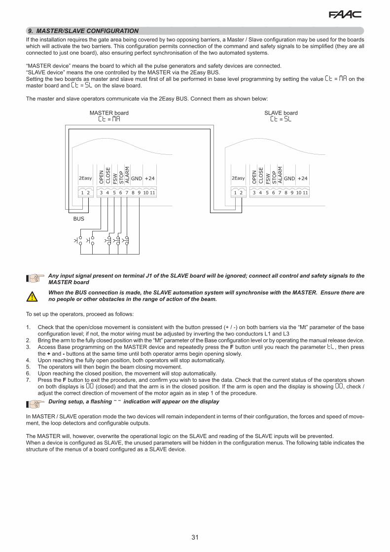
31
9. MASTER/SLAVE CONFIGURATIONIf the installation requires the gate area being covered by two opposing barriers, a Master / Slave configuration may be used for the boards which will activate the two barriers. This configuration permits connection of the command and safety signals to be simplified (they are all connected to just one board), also ensuring perfect synchronisation of the two automated systems.
“MASTER device” means the board to which all the pulse generators and safety devices are connected.“SLAVE device” means the one controlled by the MASTER via the 2Easy BUS.Setting the two boards as master and slave must first of all be performed in base level programming by setting the value Ct = MA on the master board and Ct = SL on the slave board.
The master and slave operators communicate via the 2Easy BUS. Connect them as shown below:
Any input signal present on terminal J1 of the SLAVE board will be ignored; connect all control and safety signals to the MASTER board
When the BUS connection is made, the SLAVE automation system will synchronise with the MASTER. Ensure there are no people or other obstacles in the range of action of the beam.
To set up the operators, proceed as follows:
1. Check that the open/close movement is consistent with the button pressed (+ / -) on both barriers via the “Mt” parameter of the base configuration level; if not, the motor wiring must be adjusted by inverting the two conductors L1 and L3
2. Bring the arm to the fully closed position with the “Mt” parameter of the Base configuration level or by operating the manual release device.3. Access Base programming on the MASTER device and repeatedly press the F button until you reach the parameter tL, then press
the + and - buttons at the same time until both operator arms begin opening slowly. 4. Upon reaching the fully open position, both operators will stop automatically.5. The operators will then begin the beam closing movement.6. Upon reaching the closed position, the movement will stop automatically.7. Press the F button to exit the procedure, and confirm you wish to save the data. Check that the current status of the operators shown
on both displays is 00 (closed) and that the arm is in the closed position. If the arm is open and the display is showing 00, check / adjust the correct direction of movement of the motor again as in step 1 of the procedure.
During setup, a flashing -- indication will appear on the display
In MASTER / SLAVE operation mode the two devices will remain independent in terms of their configuration, the forces and speed of move-ment, the loop detectors and configurable outputs.
The MASTER will, however, overwrite the operational logic on the SLAVE and reading of the SLAVE inputs will be prevented.When a device is configured as SLAVE, the unused parameters will be hidden in the configuration menus. The following table indicates the structure of the menus of a board configured as a SLAVE device.
2Easy
OPE
NCLO
SE
FSW
STO
PALA
RM
GND +24
1 2 3 4 5 6 7 8 9 10 11
BUS
2Easy
OPE
NCLO
SE
FSW
STO
PALA
RM
GND +24
1 2 3 4 5 6 7 8 9 10 11
MASTER boardCt = MA
SLAVE boardCt = SL

32
12 13 14 1516 17 18 19 20 21
+24
+24
+24
+24
OU
T1
OU
T2
OU
T3
GN
D
Relais
NO CO
M
OPE
NCLO
SE
FSW
STO
PALA
RM
GND +24
3 4 5 6 7 8 9 10 11
o1 = 18 P1 = no
12 13 14 1516 17 18 19 20 21
+24
+24
+24
+24
OU
T1
OU
T2
OU
T3
GN
D
Relais
NO CO
M
OPE
NCLO
SE
FSW
STO
PALA
RM
GND +24
3 4 5 6 7 8 9 10 11
o1 = 18 P1 = no
10. INTERLOCKThe interlock function enables two in-line barriers to be managed so that opening of one is subordinated to closing of the other. Operation can be one-way or two-way.
For in-line barriers, set OUT1 INTERLOCK to parameter 18 (see 2nd LEVEL PROG.) on both boards and connect them as in figure.
Base Configuration
cF 01 02 03 04 05 06dF Y Y Y Y Y YCt MA MA MA MA MA MAbu no no no no no noSo 10 10 10 10 10 10Sc 10 05 05 04 02 02S1 05 05 05 05 05 05S2 05 05 05 05 05 05
Advanced Configuration
cF 01 02 03 04 05 06FO 25 25 30 28 30 40FC 25 25 30 28 30 40oc 30 30 30 30 30 30o1 04 04 04 04 04 04P1 no no no no no noo2 03 03 03 03 03 03P2 no no no no no noo3 19 19 19 19 19 19P3 no no no no no noo4 01 01 01 01 01 01P4 no no no no no noo5 02 02 02 02 02 02P5 no no no no no noo6 04 04 04 04 04 04P6 no no no no no noo7 01 01 01 01 01 01nc 00 00 00 00 00 00nC 00 00 00 00 00 00
Expert ConfigurationcF 01 02 03 04 05 06A0 Y Y Y Y Y YA1 01 01 01 01 01 01r1 -- -- -- -- -- --r2 -- -- -- -- -- --F1 A A A A A AF2 A A A A A Ah1 no no no no no noh2 no no no no no noH1 Y Y Y Y Y YH2 Y Y Y Y Y Yt 30 30 30 30 30 30dr 04 04 04 04 04 04dG 04 04 04 04 04 04

33
LOGIC “A” PULSESAUTOMATED
SYSTEM STATUS OPEN A CLOSE STOP FSW LOOP 1 LOOP 2
CLOSEDopens and closes after the pause
timeno effect no effect
(opening inhibited) no effectopens and closes after the pause
timeno effect
WHEN OPENING no effectimmediately reverses to
closingblocks
operation no effect no effect no effect
OPEN IN PAUSE resets pause time closes blocks
operationresets pause
time(closing inhibited)
resets pause time
resets pause time
(closing inhibited)
WHEN CLOSINGimmediately reverses to
openingno effect blocks
operationimmediately reverses to
opening
immediately reverses to
opening
immediately reverses to
opening
BLOCKED closes closesno effect
(opening and closing inhibited)
no effect (closing inhibited)
opens and closes after the pause
timeno effect
(closing inhibited)
LOGIC “A1” PULSES
AUTOMATED SYSTEM STATUS OPEN A CLOSE STOP FSW LOOP 1 LOOP 2
CLOSEDopens and closes after the pause
timeno effect no effect
(opening inhibited) no effectopens and closes after the pause
timeno effect
WHEN OPENING no effectimmediately reverses to
closingblocks
operation
closes immediately
after opening is completed
no effectcloses
immediately after opening is
completed
OPEN IN PAUSE resets pause time closes blocks
operation closes resets pause time
closes when disengaged
WHEN CLOSINGimmediately reverses to
openingno effect blocks
operationimmediately reverses to
opening
immediately reverses to
opening, closes at the end of pause
immediately reverses to
opening, closes again once opening
is completed
BLOCKED closes closesno effect
(opening and closing inhibited)
inhibits closingopens and closes after the pause
time
no effect (closing
inhibited)
In brackets, the effects on the other inputs when the pulse is active
LOGIC “E” PULSESAUTOMATED
SYSTEM STATUS OPEN A CLOSE STOP FSW LOOP 1 LOOP 2
CLOSED opens no effect no effect (opening inhibited) no effect opens no effect
WHEN OPENING blocksoperation
immediately reverses to
closingblocks
operation no effect no effect no effect
OPEN closes closes no effect (closing inhibited)
no effect (closing inhibited) no effect no effect
(closing inhibited)
WHEN CLOSINGimmediately reverses to
openingno effect blocks
operationimmediately reverses to
opening
immediately reverses to
opening
immediately reverses to
opening
BLOCKED closes closesno effect
(opening and closing inhibited)
no effect (closing inhibited) opens no effect
(closing inhibited)
11. OPERATING LOGICS TABLE
Tab. 1/c
Tab. 1/b
Tab. 1/a

34
In brackets, the effects on the other inputs when the pulse is active
LOGIC “P” PULSESAUTOMATED
SYSTEM STATUS OPEN A CLOSE STOP FSW LOOP 1 LOOP 2
CLOSED opens no effect no effect (opening inhibited) no effect
opens and once opening is
completed closes if disengaged
no effect
WHEN OPENING no effectcloses
immediately after opening is completed
blocksoperation no effect no effect
closes immediately
after opening is completed
OPEN no effect(closing inhibited) closes no effect
(closing inhibited)no effect
(closing inhibited) prevents closing closes when disengaged
WHEN CLOSINGimmediately reverses to
openingno effect blocks
operation
blocks and when disengaged continues to
close
immediately reverses to opening, and once opening is completed closes if
disengaged
blocks and when disengaged continues to
close
BLOCKED opens closesno effect
(opening and closing inhibited)
no effect(closing inhibited)
opens and once opening is
completed closes if disengaged
no effect (closing inhibited)
LOGIC “PA” PULSESAUTOMATED
SYSTEM STATUS OPEN A CLOSE STOP FSW LOOP 1 LOOP 2
CLOSEDopens and closes after the pause
timeno effect no effect
(opening inhibited) no effectopens and once
opening is completed closes if
disengagedno effect
WHEN OPENING no effectcloses
immediately after opening is
completed
blocksoperation no effect no effect
closes immediately
after opening is completed
OPEN IN PAUSE resets pause time closes blocksoperation
resets pause time
(closing inhibited)resets pause time closes when
disengaged
WHEN CLOSINGimmediately reverses to
openingno effect blocks
operation
blocks and when disengaged continues to
close
immediately reverses to opening, and once opening is completed closes if if
disengaged
blocks and when disengaged continues to
close
BLOCKEDopens and closes after the pause
timecloses
no effect (opening and
closing inhibited)no effect
(closing inhibited)
opens and once opening is
completed closes if disengaged
no effect (closing inhibited)
LOGIC “Cn” PULSESAUTOMATED
SYSTEM STATUS OPEN A CLOSE STOP FSW LOOP 1 LOOP 2
CLOSED opens no effect no effect (opening inhibited) no effect opens no effect
WHEN OPENING no effectcloses
immediately after opening is
completed
blocksoperation no effect no effect
closes immediately
after opening is completed
OPEN no effect(closing inhibited) closes no effect
(closing inhibited)no effect
(closing inhibited) no effect closes when disengaged
WHEN CLOSINGimmediately reverses to
openingno effect blocks
operation
reverses to opening and closes after pause time
immediately reverses to
opening
immediately reverses to
opening
BLOCKED opens closesno effect
(opening and closing inhibited)
no effect (closing inhibited) opens no effect
(closing inhibited)
Tab. 1/e
Tab. 1/d
Tab. 1/f

35
In brackets, the effects on the other inputs when the pulse is active
LOGIC “CA” PULSESAUTOMATED
SYSTEM STATUS OPEN A CLOSE STOP FSW LOOP 1 LOOP 2
CLOSEDopens and closes after the pause
timeno effect no effect
(opening inhibited) no effectopens and closes after the pause
timeno effect
WHEN OPENING no effectcloses
immediately after opening is
completed
blocksoperation no effect no effect
closes immediately
after opening is completed
OPEN IN PAUSE resets pause time closes blocksoperation
resets pause time
(closing inhibited)resets pause time closes when
disengaged
WHEN CLOSINGimmediately reverses to
openingno effect blocks
operation
reverses to opening and clo-ses after pause
time
immediately reverses to
opening
immediately reverses to
opening
BLOCKEDopens and closes after the pause
timecloses
no effect (opening and
closing inhibited)no effect
(closing inhibited)opens and closes after the pause
timeno effect
(closing inhibited)
LOGIC “C” MAINTAINED COMMANDS PULSESAUTOMATED
SYSTEM STATUS OPEN A CLOSE STOP FSW LOOP 1 LOOP 2
CLOSED opens no effect no effect (opening inhibited) no effect no effect no effect
WHEN OPENING / no effect blocksoperation no effect no effect no effect
OPEN no effect(closing inhibited) closes blocks
operation no effect no effect(closing inhibited)
no effect(closing inhibited)
WHEN CLOSINGimmediately reverses to
opening/ blocks
operationblocks
operationblocks
operationblocks
operation
BLOCKED opens closesno effect
(opening and closing inhibited)
no effect (closing inhibited)
no effect(closing inhibited)
no effect(closing inhibited)
Tab. 1/g
Tab. 1/h

36
NOTES:
_________________________________________________________________________________________
_________________________________________________________________________________________
_________________________________________________________________________________________
_________________________________________________________________________________________
_________________________________________________________________________________________
_________________________________________________________________________________________
_________________________________________________________________________________________
_________________________________________________________________________________________
_________________________________________________________________________________________
_________________________________________________________________________________________
_________________________________________________________________________________________
_________________________________________________________________________________________
_________________________________________________________________________________________
_________________________________________________________________________________________
_________________________________________________________________________________________
_________________________________________________________________________________________
_________________________________________________________________________________________

37
NOTES:
_________________________________________________________________________________________
_________________________________________________________________________________________
_________________________________________________________________________________________
_________________________________________________________________________________________
_________________________________________________________________________________________
_________________________________________________________________________________________
_________________________________________________________________________________________
_________________________________________________________________________________________
_________________________________________________________________________________________
_________________________________________________________________________________________
_________________________________________________________________________________________
_________________________________________________________________________________________
_________________________________________________________________________________________
_________________________________________________________________________________________
_________________________________________________________________________________________
_________________________________________________________________________________________
_________________________________________________________________________________________

38
NOTES:
_________________________________________________________________________________________
_________________________________________________________________________________________
_________________________________________________________________________________________
_________________________________________________________________________________________
_________________________________________________________________________________________
_________________________________________________________________________________________
_________________________________________________________________________________________
_________________________________________________________________________________________
_________________________________________________________________________________________
_________________________________________________________________________________________
_________________________________________________________________________________________
_________________________________________________________________________________________
_________________________________________________________________________________________
_________________________________________________________________________________________
_________________________________________________________________________________________
_________________________________________________________________________________________
_________________________________________________________________________________________

39
To the original purchaser only:
FAAC International, Inc., warrants, for twenty-four (24) months from the date of invoice, the gate operator systems and other related systems and equipment manufactured by FAAC S.p.A. and distributed by FAAC International, Inc., to be free from defects in material and workmanship under normal use and service for which it was intended provided it has been properly installed and operated.
FAAC International, Inc.’s obligations under this warranty shall be limited to the repair or exchange of any part of parts manufactured by FAAC S.p.A. and distributed by FAAC International, Inc. Defective products must be returned to FAAC International, Inc., freight prepaid by purchaser, within the warranty period. Items returned will be repaired or replaced, at FAAC International, Inc.’s option, upon an examination of the product by FAAC International, Inc., which discloses, to the satisfaction of FAAC International, Inc., that the item is defective. FAAC International, Inc. will return the warranted item freight prepaid. The products manufactured by FAAC S.p.A. and distributed by FAAC International, Inc., are not warranted to meet the specific requirements, if any, of safety codes of any particular state, municipality, or other jurisdiction, and neither FAAC S.p.A. or FAAC International, Inc., assume any risk or liability whatsoever resulting from the use thereof, whether used singly or in combination with other machines or apparatus.
Any products and parts not manufactured by FAAC S.p.A. and distributed by FAAC International, Inc., will carry only the warranty, if any, of the manufacturer. This warranty shall not apply to any products or parts thereof which have been repaired or altered, without FAAC International, Inc.’s written consent, outside of FAAC International, Inc.’s workshop, or altered in any way so as, in the judgment of FAAC International, Inc., to affect adversely the stability or reliability of the product(s) or has been subject to misuse, negligence, or accident, or has not been operated in accordance with FAAC International, Inc.’s or FAAC S.p.A.’s instructions or has been operated under conditions more severe than, or otherwise exceeding, those set forth in the specifications for such product(s). Neither FAAC S.p.A. nor FAAC International, Inc., shall be liable for any loss or damage whatsoever resulting, directly or indirectly, from the use or loss of use of the product(s). Without
limiting the foregoing, this exclusion from liability embraces a purchaser’s expenses for downtime or for making up downtime, damages for which the purchaser may be liable to other persons, damages to property, and injury to or death of any persons.
FAAC S.p.A. or FAAC International, Inc., neither assumes nor authorizes any person to assume for them any other liability in connection with the sale or use of the products of FAAC S.p.A. or FAAC International, Inc. The warranty herein above set forth shall not be deemed to cover maintenance parts, including, but not limited to, hydraulic oil, filters, or the like. No agreement to replace or repair shall constitute an admission by FAAC S.p.A. or FAAC International, Inc., of any legal responsibility to effect such replacement, to make such repair, or otherwise. This limited warranty extends only to wholesale customers who buy directly through FAAC International, Inc.’s normal distribution channels. FAAC International, Inc., does not warrant its products to end consumers.
Consumers must inquire from their selling dealer as to the nature and extent of that dealer’s warranty, if any. This warranty is expressly in lieu of all other warranties expressed or implied including the warranties of merchantability and fitness for use. This warranty shall not apply to products or any part thereof which have been subject to accident, negligence, alteration, abuse, or misuse or if damage was due to improper installation or use of improper power source, or if damage was caused by fire, flood, lightning, electrical power surge, explosion, wind storm, hail, aircraft or vehicles, vandalism, riot or civil commotion, or acts of God.
LIMITED WARRANTY

© 2016, FAAC International, Inc. - All Rights Reserved
Published in Oct. 2016

T Y P I C A L I N S T A L L S P E C S F O R A & D F A A C B 6 8 0 H

EQU
IPM
ENT
SPEC

EQU
IPM
ENT
SPEC

3-1/2” 3-1/2”
3-1/2”
2-1/8”
5-3/8”
The bottom of the photo is the front of the barrier operator. From the left and right side of the oblong hole, it is best to center your stub-ups at 2" on center from either side.
FRONT OF BARRIER ARM
J Bolt Hole
J Bolt HoleJ Bolt Hole
J Bolt Hole
Oblong Hole
Potential Stub Up Location
Potential Stub Up Location
Low Voltage Conduit
High Voltage Conduit
Minimum 24”
Ideal 30”
Ideal 30” Minimum 24”
Ideal 30”
Ideal Operator Pad Size for Large Arm Operator is 30 inches x 30 inches x 30 Inches
Minimum Operator Pad Size for Large Arm Operator is 24 inches x 24 inches x 24 Inches
Please confirm in advance if you will use minimum size prior to pouring. If 24’ size is used, ground must be solid to prevent movement of the pad.
Concrete Operator Pad
Barrier Arm Operator Pad Specifications | Electrical Stub Up
QUESTIONS?Greg HolsenA&D Automatic Gate and [email protected]

Front of Operator The front of the operator is the portion of the operator which will hold the barrier arm.
Barrier Arm Operator Pad Specifications | Electrical Stub Up
QUESTIONS?Greg HolsenA&D Automatic Gate and [email protected]

810 Warrington Avenue
Redwood City, CA 94063
O 650.365.8828 x1473
M 650.224.3863
Contact:s
Peter Hartzell
Gina Navarro-Brown
[email protected]@adautogate.com
Contractors License #763182
Project1061 Saginaw TerraceSunnyvale, CA 94089
Kiel Court (HOA)
HOA Contact:Bob SoaresSenior Association ManagerCommunity Management Services, Inc.1935 Dry Creek Road #203Campbell, CA 95008
Electrical and Operator Pad Details
24”
12”
Backfilled Trench
SAN JOSÈ EVERGREEN COMMUNITY COLLEGE DISTRICT
Measure G-2010 SECTION 03 30 00 – CAST IN PLACE CONCRETE
Evergreen Valley College 32307-12 Valle Del Lago gate imprrovements
100% CD – 12/14/17 Page 1
SECTION 03 30 00
CAST-IN-PLACE CONCRETE PART 1 - GENERAL 1.01 SECTION INCLUDES
A. Concrete Forms
1. Abutments 2. Foundations 3. Retaining walls
1.02 RELATED SECTIONS
A. None 1.03 REFERENCES A. ACI 304 Recommended Practice for Measuring, Mixing, Transporting
and Placing Concrete B. ACI 305R Hot Weather Concreting C. ACI 306R Cold Weather Concreting D. ACI 308 Standard Specification for Curing Concrete E. ACI 309 Guide for Consolidation of Concrete F. ACI 315 Details and Detailing of Concrete Reinforcement G. ACI 318 Building Code Requirements for Reinforced Concrete and
Commentary H. ASTM C33 Standard Specification for Concrete Aggregates I. ASTM C94 Standard Specification for Ready-Mixed Concrete

SAN JOSÈ EVERGREEN COMMUNITY COLLEGE DISTRICT
Measure G-2010 SECTION 03 30 00 – CAST IN PLACE CONCRETE
Evergreen Valley College 32307-12 Valle Del Lago gate imprrovements
100% CD – 12/14/17 Page 2
J. ASTM C150 Standard Specification for Portland Cement K. ASTM C309 Standard Specification for Liquid Membrane-Forming
Compounds for Curing Concrete L. ASTM C494 Standard Specification for Chemical Admixtures for Concrete M. ASTM A615 Standard Specification for Plain Billet-Steel Bars for Concrete
Reinforcement N. ASTM C618 Standard Specification for Coal Fly Ash and Raw or Calcined
Natural Pozzolan for Use as a Mineral Admixture in Portland Cement Concrete
O. ASTM C979 Standard Specification for Integral Concrete Coloring System P. California Code of Regulations (CCR):
CCR Title 8, Chapter 4, Subchapter 4 – Construction Safety Orders
CCR Title 24, Part 2, California Building Code, Chapter 33, Section 3303, Protection of Pedestrians during Construction or Demolition
1.04 SUBMITTALS
A. Product Data
1. Curing / Sealing Compounds
2. Admixtures
3. Source of Concrete and Aggregates
B. Shop Drawings
1. Reinforcing Diagrams 2. Bar Schedules
C. Curing
1. Curing Method
D. Test Reports

SAN JOSÈ EVERGREEN COMMUNITY COLLEGE DISTRICT
Measure G-2010 SECTION 03 30 00 – CAST IN PLACE CONCRETE
Evergreen Valley College 32307-12 Valle Del Lago gate imprrovements
100% CD – 12/14/17 Page 3
1. Mill Test Reports
a. Reinforcing Steel
b. Cement
2. Concrete Mix Designs
Trial mixes including water-cement-fly ash ratio curves, concrete mix ingredients and proportions, and admixtures.
3. Grout Mix
To include mix ingredients, strength and shrinkage data
E. Delivery
With each batch of concrete, furnish certified delivery tickets listing information in Paragraphs 13.1 and 13.2 of ASTM C94. Maximum delivery temperature of concrete is 100 degrees Fahrenheit (F). Minimum delivery temperature as follows:
Atomospheric Temperature Minimum Concrete Temperature
30 degrees to 40 degrees F 60 degrees F
0 degrees to 30 degrees F 70 degrees F
PART 2 - PRODUCTS 2.01 MATERIALS
A. Portland Cement
Clean, fresh, Type II, low alkali, Portland cement conforming with ASTM C150.
B. Pozzolan Fly-ash to be in conformance with ASTM C618.
C. Aggregates
1. Aggregates to be uniformly graded with a one inch maximum size for all concrete mixes.

SAN JOSÈ EVERGREEN COMMUNITY COLLEGE DISTRICT
Measure G-2010 SECTION 03 30 00 – CAST IN PLACE CONCRETE
Evergreen Valley College 32307-12 Valle Del Lago gate imprrovements
100% CD – 12/14/17 Page 4
2. Natural aggregates to be free from deleterious materials, conforming to ASTM C33. Aggregate is not to be potentially reactive as defined in Appendix XI of ASTM C33. Aggregates to be thoroughly and uniformly washed before use.
D. Mixing Water
Fresh, clean, potable and free from oil, acid, alkali, organic matter or other deleterious substances.
E. Admixtures
Admixtures, if used to be of a type conforming to ASTM C494 that increases the workability of the concrete, will not impair the strength of the concrete, and is not used to reduce the cement content of the mix. Do not use Calcium Chloride.
F. Liquid Membrane-Forming Curing Compound
Is to be clear or translucent, suitable for spray application and is to conform to ASTM C309, Type 1.
G. Cement Grout
Non-shrink type composed of one part cement, two parts sand and the minimum amount of water necessary to obtain the desired consistency.
H. Properties
1. 28 day strength of concrete in place to be a minimum of:
a. 3,000 psi for walls and abutments b. 2,500 psi for drilled piers
2. The maximum water/cement ratio to be 0.44 for bridge deck. 3. Slump of concrete and not to exceed four (4) inches unless otherwise
authorized by Owner.
4. 15% of cement weight may be Pozzolan Fly-ash. Pozzolan Fly-Ash to be in conformance with ASTM C618.

SAN JOSÈ EVERGREEN COMMUNITY COLLEGE DISTRICT
Measure G-2010 SECTION 03 30 00 – CAST IN PLACE CONCRETE
Evergreen Valley College 32307-12 Valle Del Lago gate imprrovements
100% CD – 12/14/17 Page 5
2.02 REINFORCING STEEL
A. Bar reinforcement to be ASTM A615, Grade 60. (If Required) PART 3 – EXECUTION 3.01 FORMS
A. Reinforcing detailing, bending, and placing: In accordance with ACI 315 and ACI 318.
B. Reinforcing steel to be provided with the following amounts of cover for cast-in-
place concrete:
1. Concrete deposited against earth - three inches 2. Concrete surface (formed) exposed to earth or weather:
a. #6 through #18 bars - two inches b. #5 bar and smaller - 1-1/2 inches
C. All reinforcing steel, anchor bolts, dowels, and inserts to be accurately placed and
securely held in place prior to placing of concrete or grout. D. Horizontal bars to lap a minimum of 16 gauge black annealed wire chairs or concrete
“dobies.” 3.02 MIXING CONCRETE
A. All concrete materials to be measured accurately for each batch and mixed thoroughly until aggregate is coated with mortar. Combined ingredients to be mixed for a minimum of 1-1/2 minutes.
B. Concrete batching and mixing to comply with ACI 318 and ASTM C94, delivered to
site. Batch mixing at the Site is not permitted. 3.03 PLACING CONCRETE
A. Preparation
1. Remove hardened concrete, wood chips, shavings and other debris from forms.

SAN JOSÈ EVERGREEN COMMUNITY COLLEGE DISTRICT
Measure G-2010 SECTION 03 30 00 – CAST IN PLACE CONCRETE
Evergreen Valley College 32307-12 Valle Del Lago gate imprrovements
100% CD – 12/14/17 Page 6
2. Remove hardened concrete and foreign materials from interior surfaces of
mixing and conveying equipment. 3. Have reinforcement inspected and approved by Owner before depositing
concrete. 4. Forms and reinforcing bars to be clean and wetted prior to placing of the
concrete. 5. Place anchor bolts and other embedments, as indicated.
B. Conveying Concrete
Convey concrete from mixer to final place of deposit by a method that will prevent segregation. Method of conveying concrete is subject to approval of Owner.
C. Placing
1. Concrete to be placed in conformance with the recommendations of ACI
304. 2. Do not place concrete when weather conditions prevent proper placement
and consolidation, or when concrete has attained its initial set, or has contained its water or cement content more than 1-1/2 hours.
3. Deposit concrete as near as practicable in its final position. Prevent
splashing of forms or reinforcement with concrete in advance of placing concrete.
4. Do not drop concrete freely more than five feet. Where greater drops are
required, use a tremie or flexible spout attached to a suitable hopper. 5. Discharge contents of tremies or flexible spouts in horizontal layers not
exceeding 20 inches in thickness, and space tremies such as to provide a minimum of lateral movement of concrete.
6. Continuously place concrete until an entire unit between construction joints
is placed. Rate and method of placing concrete to be such that no concrete between construction joints will be deposited upon or against partly set concrete.

SAN JOSÈ EVERGREEN COMMUNITY COLLEGE DISTRICT
Measure G-2010 SECTION 03 30 00 – CAST IN PLACE CONCRETE
Evergreen Valley College 32307-12 Valle Del Lago gate imprrovements
100% CD – 12/14/17 Page 7
7. Continuously place all concrete with no more than 10 minutes elapsed time between pours. Sequence concrete pours such that each pour is placed on or adjacent to concrete that has been in place no more than 10 minutes.
D. Consolidation
Conform to ACI 309. Immediately after depositing, spade concrete next to forms, into corners and recesses, work around reinforcement and into angles of forms, tamp lightly by hand, and compact with mechanical vibrator. Vibrate concrete to produce thorough compaction, leaving no voids, complete embedment of reinforcement and concrete of uniform and maximum density without segregation of mix. Do not transport concrete in forms by vibration. Carry on vibration continuously with placing of concrete. Do not insert vibrator into concrete that has begun to set.
3.04 HOT OR COLD WEATHER
A. Follow the recommendations of ACI 305R and ACI 306R for hot and cold weather conditions.
3.05 CONCRETE FINISHES
A. Finish of formed surfaces to be smooth and free of fins, honeycomb, or segregation. When defects occur, they are to be remedied by chipping cavities and patching, or by other methods approved by Owner.
B. Exposed surfaces to be “sacked” by rubbing cement mortar into voids with burlap
or canvas. Fins to be ground smooth and loose mortar to be removed. C. Vertical edges of the walls to have 3/4-inch chamfer. D. Horizontal edges of the walls to have ½-inch chamfer. E. Unformed surfaces to be steel troweled to a smooth dense finish. After the trowel
finish has sufficiently hardened, walking surfaces of the entire surface to be given a medium broom finish perpendicular to the direction of travel. The broom finish to be applied just prior to the application of the curing compound/sealer.
3.06 PROTECTION AND CURING
A. In conformance with ACI 308, except as otherwise specified herein. B. Initial curing to immediately follow the finishing operation. Protect exposed surfaces
of concrete from premature drying, wash by rain and running water, wind,

SAN JOSÈ EVERGREEN COMMUNITY COLLEGE DISTRICT
Measure G-2010 SECTION 03 30 00 – CAST IN PLACE CONCRETE
Evergreen Valley College 32307-12 Valle Del Lago gate imprrovements
100% CD – 12/14/17 Page 8
mechanical injury, and excessively hot or cold temperatures. Concrete not covered with membrane or other curing material to be kept continuously wet for at least seven days after placing. High-early-strength concrete net curing period to be not less than three days. Keep wood forms continuously wet to prevent moisture loss until forms are removed. Cure exposed concrete surfaces as described below. Other curing methods may be used if approved by Owner.
1. Liquid Curing and Sealing Compounds
Apply by spray or roller in accordance with the manufacturer's instructions. Apply immediately after finishing. Maximum coverage to be 400 square feet per gallon on steel troweled surfaces, and 300 square feet per gallon on floated or broomed surfaces for the curing/sealing compound.
2. Plastic sheets
Apply as soon as concrete has hardened sufficiently to prevent surface damage. Utilize widest practical width sheet and overlap adjacent sheets two inches. Tightly seal joints with tape.
3. Paper
Utilize widest practical width paper and overlap adjacent sheets two inches. Tightly seal joints with sand, wood planks, pressure-sensitive tape, mastic or glue.
C. Provisions are to be made to keep overspray for curing/sealing compounds from
extending beyond bridge deck surface. Spray of curing/sealing compounds to cease if sustained winds exceed 10 miles per hour.
3.07 CLEANING
A. Cleaning of equipment for delivery or placement of concrete is prohibited on site. 3.08 ACCEPTANCE
A. Walking surfaces are to be free from trowel marks, uniform in appearance and with a surface plane tolerance not exceeding 1/4 inches in any 10 foot 0 inch when tested with a ten foot straightedge.
END OF SECTION