Embed Size (px)
Citation preview

Addendum No. 3 Naco Pump Station Improvements Project SAWS Project No. 12‐6003 Solicitation No. B‐14‐005‐DD
K:\SNA_Utilities\068665010\DESIGN\SPECS\REBID ADDENDUM NO 3\Addendum No 3‐LMR.doc AD‐1
SAN ANTONIO WATER SYSTEM NACO PUMP STATION IMPROVEMENTS PROJECT
SAWS PROJECT NO. 12‐6003 SOLICITATION NO. B‐14‐005‐DD
ADDENDUM NO. 3
February 20, 2014 This addendum, applicable to work designated above, is an amendment to the proposal and specification documents and as such shall be a part of and included in the Contract. Acknowledge receipt of this addendum by entering the addendum number and issue date in the spaces provided on all submitted copies of the proposal. 1.0 Addenda Purpose
The purpose of this addendum is to issue a revision to the Contract Documents, plans and specifications for the Naco Pump Station Improvements Project (SAWS Job No. 12‐6003).
2.0 Modifications to Part I – CONTRACT DOCUMENTS
A. PRICE PROPOSAL – DELETE the Price Proposal in its entirety and REPLACE with the Price Proposal provided in Addendum No. 3.
B. INSERT the Texas Water Development Board Form SRF‐404, provided in this
Addendum No. 3 into the CONTRACT DOCUMENTS.
C. SUPPLEMENTARY INSTRUCTIONS TO RESPONDENTS – Article C(1)(f). DELETE and REPLACE the first sentence with the following: “Provide experience of the CONSTRUCTION TEAM as it relates to the constructing of at least three (3) potable water pump stations within the last ten (10) years with a minimum total design output of fifteen (15) MGD each, involving the installation of above and below ground station piping with a minimum of 24‐inch diameter, as well as the installation of 4,160 voltage motor control centers with at least four (4) motor starters.”
D. SPECIAL CONDITIONS. ADD the following paragraph:
5.0 Construction Trailer and Laydown Area: SAWS Lot 45 located immediately
adjacent to the Northeast Service Center can be used for the Contractor’s laydown area. See hatched area in the enclosed site map at the end of this addendum. However, Contractor shall not be allowed to remove any trees or place any materials in the 100‐year floodplain. In addition, the Contractor must maintain this Lot 45 clean throughout the entire construction duration by mowing the grass and collecting trash, etc. Lot 45 must be restored to its original or better condition following the specifications under Division 2 including, but not limited to, Soil Preparation, Vegetation Restoration, etc. Site security shall be maintained

Addendum No. 3 Naco Pump Station Improvements Project SAWS Project No. 12‐6003 Solicitation No. B‐14‐005‐DD
K:\SNA_Utilities\068665010\DESIGN\SPECS\REBID ADDENDUM NO 3\Addendum No 3‐LMR.doc AD‐2
at the Contractor’s expense. Contractor shall use Nacogdoches Road entrance gate to access Naco Pump Station throughout construction. Access through the SAWS Northeast Service Center entrance gate shall not be allowed.”
ADD the attached SAWS Daily Construction Report form to the end of this section.
3.0 Modifications to Part II – TECHNICAL SPECIFICATIONS
A. TABLE OF CONTENTS – ADD the following specification sections to the Table of Contents, Part II Technical Specifications, Division 2 – Site Work: 02360 Vegetation Restoration 02481 Tree and Landscape Protection
B. SECTION 01270 MEASUREMENT AND PAYMENT – Article 1.04(E)(2). DELETE and REPLACE with the following: “Measurement – Measurement of the item “CPS Energy Allowance” will be by lump sum and shall not exceed $30,000.00.”
C. SECTION 01400 QUALITY CONTROL – Article 1.02(D)(1)(e)(v). ADD the following to the end of this section: “(g) Provide qualifications for all testing personnel, including ACI certifications.”
D. SECTION 02200 EARTH EXCAVATION, BACKFILL, FILL AND GRADING – Article 1.01. ADD the following:
“H. Refer to Section 13205 for excavation and backfill requirements associated with
the proposed ground storage tank.”
E. SECTION 02360 VEGETATION RESTORATION – ADD the following specification.
F. SECTION 02481 TREE AND LANDSCAPE PROTECTION – ADD the following specification.
G. SECTION 02615 DUCTILE IRON PIPE AND FITTINGS – Article 2.04(F). DELETE the fourth sentence and REPLACE with the following:
“Coating shall be Xylan® (as manufactured by Whitford Corporation), Cor‐Blue (as manufactured by NSS Industries), or approved equal.”
H. SECTION 02617 STEEL PIPE – Article 2.02(A)(1)(b)(i). DELETE and REPLACE with the following: “i. Working Pressure = 200 psi minimum for all piping.”
Addendum No. 3 Naco Pump Station Improvements Project SAWS Project No. 12‐6003 Solicitation No. B‐14‐005‐DD
K:\SNA_Utilities\068665010\DESIGN\SPECS\REBID ADDENDUM NO 3\Addendum No 3‐LMR.doc AD‐3
I. SECTION 02617 STEEL PIPE – Article 2.02(A)(1)(b)(ii). DELETE and REPLACE with the following: “ii. Surge Allowance = 50 psi minimum. Total Pressure = Working Pressure + Surge
Allowance.”
J. SECTION 02617 STEEL PIPE – Article 2.02(B)(3). DELETE the last sentence and REPLACE with the following: “Flanges shall be Class E in accordance with AWWA C207 and drilled in accordance
with ANSI B16.1 Class 125.”
K. SECTION 02910 SOIL PREPARATION – DELETE this section in its entirety and REPLACE with the attached Specification Section 02910 Soil Preparation.
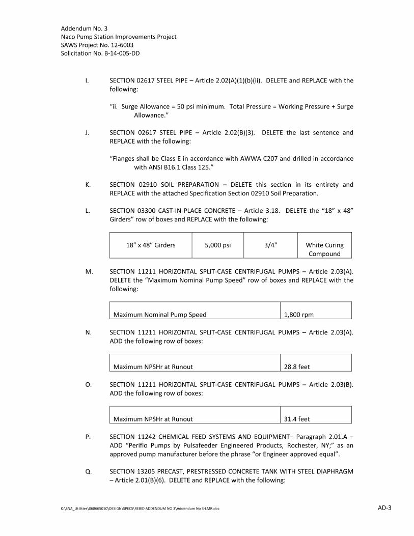
L. SECTION 03300 CAST‐IN‐PLACE CONCRETE – Article 3.18. DELETE the “18” x 48” Girders” row of boxes and REPLACE with the following:
18” x 48” Girders 5,000 psi 3/4" White Curing Compound
M. SECTION 11211 HORIZONTAL SPLIT‐CASE CENTRIFUGAL PUMPS – Article 2.03(A).
DELETE the “Maximum Nominal Pump Speed” row of boxes and REPLACE with the following:
Maximum Nominal Pump Speed 1,800 rpm
N. SECTION 11211 HORIZONTAL SPLIT‐CASE CENTRIFUGAL PUMPS – Article 2.03(A).
ADD the following row of boxes:
Maximum NPSHr at Runout 28.8 feet
O. SECTION 11211 HORIZONTAL SPLIT‐CASE CENTRIFUGAL PUMPS – Article 2.03(B).
ADD the following row of boxes:
Maximum NPSHr at Runout 31.4 feet
P. SECTION 11242 CHEMICAL FEED SYSTEMS AND EQUIPMENT– Paragraph 2.01.A –
ADD “Periflo Pumps by Pulsafeeder Engineered Products, Rochester, NY;” as an approved pump manufacturer before the phrase “or Engineer approved equal”.
Q. SECTION 13205 PRECAST, PRESTRESSED CONCRETE TANK WITH STEEL DIAPHRAGM
– Article 2.01(B)(6). DELETE and REPLACE with the following:

Addendum No. 3 Naco Pump Station Improvements Project SAWS Project No. 12‐6003 Solicitation No. B‐14‐005‐DD
K:\SNA_Utilities\068665010\DESIGN\SPECS\REBID ADDENDUM NO 3\Addendum No 3‐LMR.doc AD‐4
“6. Seismic loads shall be based on ACI 350.3 with an ASCE 7 Site Class of D, a short period acceleration (Ss) of 0.104g, a 1‐second (S1) acceleration of 0.031g and an importance factor of 1.25.”
R. SECTION 15088 FLEXIBLE JOINTS AND COUPLINGS – Article 2.01(A)(1)(a). DELETE
and REPLACE with the following: “a. Working Pressure = 200 psi minimum for all piping.”
S. SECTION 15088 FLEXIBLE JOINTS AND COUPLINGS – Article 2.01(A)(1)(b). DELETE in its entirety.
T. SECTION 15088 FLEXIBLE JOINTS AND COUPLINGS – Article 2.01(A)(1)(c). DELETE and REPLACE with the following: “c. Surge Allowance = 50 psi minimum. Total Pressure = Working Pressure + Surge
Allowance.”
U. SECTION 15088 FLEXIBLE JOINTS AND COUPLINGS – Article 2.01(D). DELETE and REPLACE with the following: “D. Flanges shall be Class E in accordance with AWWA C207.”
V. SECTION 15088 FLEXIBLE JOINTS AND COUPLINGS – Article 2.02(A)(1)(a). DELETE and REPLACE with the following: “a. Working Pressure = 200 psi minimum for all piping.”
W. SECTION 15088 FLEXIBLE JOINTS AND COUPLINGS – Article 2.02(A)(1)(b). DELETE in its entirety.
X. SECTION 15088 FLEXIBLE JOINTS AND COUPLINGS – Article 2.02(A)(1)(c). DELETE and REPLACE with the following: “c. Surge Allowance = 50 psi minimum. Total Pressure = Working Pressure + Surge
Allowance.”
Y. SECTION 15088 FLEXIBLE JOINTS AND COUPLINGS – Article 2.02(B). DELETE and REPLACE with the following:
i. “B. Flanges shall be Class E in accordance with AWWA C207.” Z. SECTION 15090 BALL VALVES AND ELECTRIC ACTUATORS – Article 2.01(H). DELETE
and REPLACE with the following: “H. All ball valves shall be coated with either 1) a fusion bonded epoxy coating, 25 mils minimum dry film thickness, or 2) a two‐part epoxy coating system with a minimum dry film thickness of 10‐12 mils. Refer to Section 09902 for full coating system requirements.

Addendum No. 3 Naco Pump Station Improvements Project SAWS Project No. 12‐6003 Solicitation No. B‐14‐005‐DD
K:\SNA_Utilities\068665010\DESIGN\SPECS\REBID ADDENDUM NO 3\Addendum No 3‐LMR.doc AD‐5
AA. SECTION 15092 BUTTERFLY VALVES – Article 2.01(H). DELETE and REPLACE with the
following: “H. All butterfly valves shall be coated with either 1) a fusion bonded epoxy coating, 25 mils minimum dry film thickness, or 2) a two‐part epoxy coating system with a minimum dry film thickness of 10‐12 mils. Refer to Section 09902 for full coating system requirements.
BB. SECTION 16110 – RACEWAYS – Article 2.03 C: ADD the following: 1. “3. All rigid galvanized conduit shall be wrapped where in contact with concrete
and/or soil. Wrap conduits 6” above contact point with soil and/or concrete.”
CC. SECTION 16110 – RACEWAYS – Article 3.05 C: ADD the following: 1. “Wrap rigid steel conduit per section 2.03 C.”
DD. SECTION 17515 – COMMUNICATIONS INTERFACE EQUIPMENT – Article 2.05 B: REMOVE existing list and REPLACE with the following:
DESCRIPTION MANUFACTURER PART NUMBER QUANTITY
Explore Air ‐ Radio 11.2‐11.4 GHZ Exalt E11E741‐0490H1 1 Explore Air ‐ Radio 10.7‐10.9 GHZ Exalt E11E741‐0490L1 1 Explore Air ‐ AC Power Kit, Single Terminal Exalt A204789 2 Explore Air ‐ Upgrade Key 100 to 500 Mbps Exalt K03BXXXX41 2 3‐year Warranty Extension, Single terminal Exalt S002T04 2 10.7‐11.7GHZ 3’ Dish Antenna Radio Waves HP3‐11EX 2 Pole Mounting Kit Poly Phaser IX‐POLE‐KIT 2 Surge Protection Poly Phaser IXG‐05 4 Radio 4.9‐5.85 GHz Redline 3KRR‐G‐G‐T5X‐GPS 4 Frequency Engineering & Coordination Redline FCC App & Eng 1 PMP Sector Controller Software Redline MSV‐SC‐512 4 AC Power input Redline 80i‐POE‐1A 4 Flat Panel Dual‐polarization Antenna Redline A9014MTD 4 4.9‐5.9 GHz, 14 dBi, 90 degree AC POWER CORD Redline PPT‐B 4 PTP to PMP upgrade for security Redline SecurelinkSC 4 Heavy Duty Mast Mounting Kit Redline 3K‐HD‐MNT 4 GPS Antenna Installation Kit Redline 3K‐GPS‐ANT 1 Sync Cable Kit Redline 3K‐SYNC‐CBL 2 Omni‐Directional Antenna Kathryn Scala OGB9‐915N 2 900MHZ Spread Spectrum Radio (Wells) GE‐MDS Transnet 900 1 Trio JR Ethernet Radio Schneider Electric TBURJ‐R900‐00‐002‐E‐H‐0 1
4.0 Modifications to Part III – PLANS FOR CONSTRUCTION
A. DELETE the following Plan Sheets and REPLACE with the Plan Sheets included with Addendum No. 3:

Addendum No. 3 Naco Pump Station Improvements Project SAWS Project No. 12‐6003 Solicitation No. B‐14‐005‐DD
K:\SNA_Utilities\068665010\DESIGN\SPECS\REBID ADDENDUM NO 3\Addendum No 3‐LMR.doc AD‐6
Sheet C19 – Grading, Paving & Erosion Control (2 of 5) Sheet C20 – Grading, Paving & Erosion Control (3 of 5) Sheet C21 – Grading, Paving & Erosion Control (4 of 5) Sheet C22 – Grading, Paving & Erosion Control (5 of 5) Sheet C29 – Service Level 9 Pump Station Plan View Sheet C30 – Service Level 9 Pump Station Plan View Sheet C47 – Miscellaneous Details (6 of 6) Sheet E11 – Proposed One‐Line Diagram – Part 1 Sheet E38 – Security System Connection Diagram
B. SHEET C23 – PIPING PLAN (1 OF 2) – ADD note 9 to read as the following: “Existing 60” BFV and existing harnessed mechanical coupling to be replaced on
the 60” inlet of the existing 7.5 MG GST.”
C. SHEET C24 – PIPING PLAN (2 OF 2) – REVISE note on existing 7.5 MG GST outlet piping to read as the following: “Existing 48” BFV and existing harnessed mechanical coupling to be replaced.
See sheet C5A for valve locations.”
D. SHEET C25 – WATER PIPING PROFILES (1 OF 2) – REVISE and REPLACE the 4” schedule 40 PVC note on WATER LINE A with the following: “4” Ductile Iron piping”
E. SHEET A‐6 – ON‐SITE GENERATION BUILDING – REVISE and REPLACE the galvanized grating note on FLOOR PLAN Section 1 with the following: “Dotted line indicates FRP grate platform”
F. SHEET E24 – ELECTRICAL SITE PLAN – Add the following note to the Notes list:
“7. Ductbank #1 should be routed around the proposed sump pump vault.”
“8. The contractor shall hire an engineer registered in the State of Texas to provide signed and sealed calculations illustrating that all existing vault walls are structurally adequate once the required ductbank penetration is made in the existing concrete wall. If analysis demonstrates that the area around the penetration should be reinforced then the contractor’s engineer shall determine the means and extent of reinforcement required. For bidding purposes, the contractor shall assume the installation of 40' of W8x31 beams along with any necessary gussets, bolts, welds, and incidentals shall be required.”
G. SHEET E33B – CABLE/CONDUIT DUCTBANK SECTIONS –VIII – ADD the following:
Ductbanks 589, 590 & 593: Add section ID 13B to each.
Addendum No. 3 Naco Pump Station Improvements Project SAWS Project No. 12‐6003 Solicitation No. B‐14‐005‐DD
K:\SNA_Utilities\068665010\DESIGN\SPECS\REBID ADDENDUM NO 3\Addendum No 3‐LMR.doc AD‐7
H. SHEET E80 – ELECTRICAL MISCELLANEOUS DETAILS – 1 – ADD the following note to detail D – Pre‐Cast Vault Detail:
“Provide OSHA compliant ladder with safety climb system in all vaults.
Reference Sheet C39 detail 2 for ladder details.”
5.0 Questions and Answers
Q1: Are Subcontractors required to attend the mandatory Pre‐Proposal Site Visit meeting that is being held February 11, 2014 at 10:00 a.m. or is this requirement only for the General Contractors that plan on submitting a proposal for this project?
Response: As indicated in the Invitation for Competitive Sealed Proposals, if you are a
General Contractor that intends to submit a proposal, then you were required to attend and sign in at the Mandatory Site Visit that was held on February 11, 2014. The sign‐in sheet can be referenced in Addendum No. 2, issued on February 14, 2014.
Q2: If the 4‐foot excavation recommended in Table 7 of the January 18, 2013
Geotechnical Report encounters fat clay, should the excavation continue until all the fat clay is removed? (For example, this might be the case near Boring B‐5, which indicates fat clay to a depth of 5 feet)
And if the answer is Yes, and the resulting overexcavation is authorized by the Owner, what provisions of the project documents apply: Those of Section 02200‐3.02.B.4.d(4), or Section 13205‐2.01.F?
Response: The intent is to remove all clays as described in Note 2 of Table 7 of the
Geotechnical Report, which may require excavations in excess of 4 feet. The contractor should assume excavations of at least 5 feet, for bidding purposes. The provisions of Section 13205, Part 2.01(F) shall apply. Technical Specification 02200 has been updated to provide further clarification. Reference Part 3.0 of this Addendum.
Q3: According to page 13 of the Geotechnical Report, the site classification is Site
Class D. However, according to Section 13205‐2.01.B.6 of the tank specs, the site classification is Site Class B. What is the correct seismic site classification?
Response: The seismic classification has been updated in Technical Specification 13205.
Reference Part 3.0 of this Addendum. Q4: Specification Section 02615 DIP and Fittings 2.02 C. requires that the t‐head
bolts for the MJ fittings to be coated with ceramic‐filled, baked‐on fluorocarbon resin; Xylan colored white a proprietary product of the Whitford Corp.
SAWS specification does not require MJ T‐head bolts to be coated with a ceramic‐filled, baked‐on fluorocarbon resin. The industry standard for coating T‐Head bolts with ceramic‐filled, baked‐on fluorocarbon resin is Cor‐Blue. Will a ceramic‐filled, baked‐on fluorocarbon resin coating be required on the MJ T‐

Addendum No. 3 Naco Pump Station Improvements Project SAWS Project No. 12‐6003 Solicitation No. B‐14‐005‐DD
K:\SNA_Utilities\068665010\DESIGN\SPECS\REBID ADDENDUM NO 3\Addendum No 3‐LMR.doc AD‐8
Head bolts? If so, will the industry standard Cor‐Blue be allowed in addition to the Xylan?
Response: The ceramic‐filled, baked‐on fluorocarbon resin will be required. The Cor‐Blue‐
coated T‐head bolts will be allowed in addition to the Xylan‐coated T‐head bolts. Technical Specification 02615 has been updated. Reference Part 3.0 of this Addendum.
Q5: I see the Naco Pump Station is back out for bid and there is a mandatory site
visit next Tuesday. Are we allowed to bid on this project if we did not attend the original pre‐bid in December?
Response: The requirements of the original Request for Competitive Sealed Proposals
(Solicitation No. B‐13‐021‐DD) do not apply to this current Request for Competitive Sealed Proposals (Solicitation No. B‐14‐005‐DD).
Q6: Specification Section 02617 2.02 A.1.b.i. 1. “SL9 Pump Station Piping… =
200wpsi” Specification Section 02617 2.02 A.1.b.i. 2. “All Other Piping… = 150wpsi” Specification Section 02617 2.02 A.1.b.ii. “Surge Allowance = 100psi minimum.
Total Pressure = Working Pressure + Surge Allowance” Specification Section 02617 2.02 B.3. “For Fittings with Flanges: …Pipe flanges
shall be of rated pressure equal to or greater than the adjacent pipe class. Flanges shall match the fittings or appurtenances which are to be attached. Flanges shall be Class F in accordance with AWWA C207 and drilled in accordance with ANSI B16.1 Class 125
Specification Section 02617 2.01 C. indicate the bolts class and seem to indicate that there may be a variety of Steel Flange Classes “B”, “D”, “E” or “F” flanges
Steel Flange Classes – Class “D” 150# Bolt Pattern/175‐150psi; Class “E” 150# Bolt Pattern/275psi; Class “F” 250# Bolt Pattern/300psi
‐ These class psi ratings indicate max pressure (no surge allowance) All of the AWWA Valves specified on the project are 150# Bolt Pattern;
however they vary in working and test pressures but all are under 250psi It seems a universal Class “E” Steel Flange system would cover all pressure
requirements while allowing for mating to the currently spec’d valves…will you clarify the class type of steel flanges you would like for the individual systems or for the whole project (from Class “D”,“E” or “F” flanges)?
Response: The design pressure and flange requirements have been modified in Technical
Specifications 02617 and 15088. Reference Part 3.0 of this Addendum. Q7: Pumps and Controls, Inc. would like to be named as an approved systems
integrator for the chemical feed pumps and accessories specified in the above project.
Pumps and Controls, Inc., since 1986, is a master distributor for LMI chemical
dosing pumps for Texas, Louisiana, Oklahoma, Arkansas, New Mexico, and Mississippi.

Addendum No. 3 Naco Pump Station Improvements Project SAWS Project No. 12‐6003 Solicitation No. B‐14‐005‐DD
K:\SNA_Utilities\068665010\DESIGN\SPECS\REBID ADDENDUM NO 3\Addendum No 3‐LMR.doc AD‐9
At Pumps and Controls, Inc., we custom build chemical feed systems and can act as a systems integrator for projects with chemical feed equipment needs. This includes, and not limited to, equipment selection, development of specifications, provide startup, training, installation, and service.
I have attached a catalog which will provide you with a detailed overview of our
products and services. Thank you for considering Pumps and Controls, Inc. as a strategic partner to
supply chemical feed equipment for this project. Response: Technical Specification 11242 lists chemical equipment approved for this
project. Pumps and Controls, Inc. is welcome to bid the chemical system, provided that their equipment meets the specifications. See Division 16 for the approved list of process control integrators
Q8: I wanted to touch base with you and provide you with some information
on Periflo equipment after reviewing the above project. I am including a reference page of customers along with hundreds of installations. We have been in business since 1988 installing, troubleshooting, repairing, and servicing chlorination equipment. We service the majority of the WP's, WWTP's, WCID's, and MUD's in the Houston and surrounding areas to the south,east,west and north. Although we service and have installed all major brands of chemical feed equipment, we are able to offer the customer a discount off of Pulsafeeder equipment. If you need any more information from me please let me know. James Manuel would be happy to help in any way with technical information/questions if you need any assistance in planning any job in the future. We can assist with drawings if needed as well. We look forward to working with you on this and future projects. I would appreciate your consideration of Periflo equipment as an approved equal on the above mentioned project instead of just Watson Marlow peristaltic pumps in order to provide the customer a competitive bid. Thank you again for your time in advance.
The following are some links for Periflo peristaltic pumps: http://www.pulsa.com/products/pumps/periflo‐series/periflo‐fmp/periflo‐fmp‐
30 http://pulsa.salesmrc.com/Details.aspx?ID=2774 http://www.pulsa.com/products/pumps/periflo‐series/periflo‐rbt/periflo‐rbt‐
70 http://pulsa.salesmrc.com/Details.aspx?ID=2775 Response: The list of pump manufacturers has been updated in Technical Specification
11242. Reference Part 3.0 of this Addendum. Q9: Item 1.06.D.3 and 2.03.B [Clarification]: The specs require the pumps to receive
a 1 pt NPSHr test with a margin of 25%. The pumps will meet this requirement. Note that the 8LR‐18S will have NPSHr of 37ft at run‐out. NPSHa at run‐out is

Addendum No. 3 Naco Pump Station Improvements Project SAWS Project No. 12‐6003 Solicitation No. B‐14‐005‐DD
K:\SNA_Utilities\068665010\DESIGN\SPECS\REBID ADDENDUM NO 3\Addendum No 3‐LMR.doc AD‐10
not specified. NPSHa at design is 39.3ft. If this is the NPSHa at run‐out, max flow will be 5,500gpm to maintain 25% margin. Please confirm this is acceptable.
Response: The maximum allowable NPSH required at runout has been added to Technical
Specification 11211. Reference Part 3.0 of this Addendum. Q10: Item 1.06. I [Clarification]: This section requires testing with the job motor. The
Chesapeake factory test stand cannot accommodate 4160V motors. Will the Engineer allow testing with factory calibrated motor? Flowserve will not meet the specification without this change.
Response: The requirements of Technical Specification 11211, Part 1.06 will not be
modified at this time. Q11: Item 2.03.B [Clarification]: The specs I have are showing the condition is still
335ft @2000gpm. The TDH at the secondary capacity will be 325ft. Please confirm this is acceptable. Flowserve will not meet the specification without this change.
Response: The secondary head of 325 feet instead of 335 feet will be acceptable, provided
that all other requirements for Pumps 4‐9 and 5‐9 identified in Technical Specification 11211 are met.
Q12: Regarding the Painting on Butterfly section 15092 and Ball Valves section 15090 Both specifications, in paragraph 1.02 “Quality Assurance”, reference San
Antonio Water System (SAWS) latest specifications and American Water Works Association (AWWA), AWWA C504. Both allow either a 2 part epoxy coating or fusion bond epoxy coatings. Paragraph 2.01 paragraph H states “…valves shall be coated with a fusion bonded epoxy coating, 25 mils minimum dry film thickness. “ Is a two part epoxy coating per the reference SAWS and AWWA specification allowable, and if so, what thickness.
Please see below: Naco Project Specifications: Section 15092 Part 1 ‐ General 1.02 – Quality Assurance: A – References: 1 ‐ San Antonio Water System (SAWS) latest specifications.
This Reads as Follows: SAWS Material Specifications: Valve Butterfly 150‐250 Dec 12 5. PAINTING
Addendum No. 3 Naco Pump Station Improvements Project SAWS Project No. 12‐6003 Solicitation No. B‐14‐005‐DD
K:\SNA_Utilities\068665010\DESIGN\SPECS\REBID ADDENDUM NO 3\Addendum No 3‐LMR.doc AD‐11
a. All interior and exterior ferrous surfaces of the valve, including the disc, shall be coated with epoxy, N.S.F. 61 certified or fusion bonded epoxy, N.S.F.61 certified. The epoxy (or fusion bonded epoxy) shall have a nominal thickness of 8 mils, and shall be in accordance with AWWA C550, latest revision.
Naco Project Specifications: Section 15092 Part 1 ‐ General 1.02 – Quality Assurance: A – References: 2. American Water Works Association (AWWA) This Reads as Follows: ANSI/AWWA –C504‐10 Rubber‐Seated Butterfly Valves, 3In. Through 72 In. Sec. 4.4 Coatings
4.4.1 Interior and exterior surfaces. Interior surfaces of valves and exterior
surfaces of buried valves, except stainless steel, machined, or bearing surfaces, shall be shop‐coated with an epoxy coating conforming to the requirements of ANSI/AWWA C550 to a minimum dry film thickness of 8 mil and when required in the purchase documents shall be NSF/ANSI 61 Approved.
Response: The allowable coating systems for the butterfly and ball valves have been
updated in Technical Specifications 15090 and 15092. Reference Part 3.0 of this Addendum.
Q13: Please review the attached pump curve from Patterson Pump. Patterson is
listed and can meet all requirements with the exception of the 1200 rpm restriction. Is the attached 1800 rpm pump acceptable?
Response: The pump speed requirements in Technical Specification 11211 have been
modified. Reference Part 3.0 of this Addendum. Q14: 1. SIR‐2, C.f states three (3) potable water pump station with a minimum total design output of thirty (30) MGD. Does each pump station need to be thirty
(30) MGD or is that a total of 30 MGD for all three (3)? 2. SIR‐2, C.f states potable water pump stations only. Is there a reason wastewater pump stations cannot be included? I ask that wastewater pump
stations be included in the criteria. Response: The potable water pump station experience requirements in the Supplementary
Instructions to Respondents have been modified. Reference Part 2.0 of this Addendum. Wastewater pump stations cannot be included to satisfy the requirements of this section.

Addendum No. 3 Naco Pump Station Improvements Project SAWS Project No. 12‐6003 Solicitation No. B‐14‐005‐DD
K:\SNA_Utilities\068665010\DESIGN\SPECS\REBID ADDENDUM NO 3\Addendum No 3‐LMR.doc AD‐12
Q15: Why is construction of the proposed 5.0 GST dependent on completion of the OSG Containment Building? I do not see how that would impact construction of the new GST.
Response: Naco Pump Station shall remain operational at all times throughout the
construction phase. Therefore, chlorine and fluoride facilities must be accessible for daily deliveries. Access to the chlorine and fluoride facilities will occur from the South side of the buildings during construction of the OSG Containment. The conflicts and phasing are described on Sheet C4 under the "Warnings ‐E" section.
Q16: Will there be room on‐site for a construction trailer and laydown area? Response: The contractor shall become familiar with the site in order to determine
location of on‐site trailer and laydown area prior to submitting his proposal to the Owner. Site shall remain accessible to SAWS maintenance personnel throughout construction. In addition, Lot 45 located immediately adjacent to SAWS Northeast Service Center can be used for the Contractor’s laydown area. Reference Part 2.0 of this Addendum.
Q17: I do not see where there are any Existing grade line elevations called out on
sheets C18‐C22. Only Proposed grade elevations. Please advise. Response: Existing grade line elevations have been added to Sheets C18‐C22. Reference
Part 4.0 of this Addendum. Q18: Looking at the Naco Pump Station Improvements Project, how would I go by
getting Team One Integration, LLC onto the Application System Provider (ASP) list in division 17300, Part 1.05 C of the specification?
Response: Interested firms must meet the requirements stipulated in Technical
Specification 17300. Please note that the firms listed in 1.05(C) of this section are recommended.
Q19: Sheet C48 is a detail for TXDOT Guardrail. I do not see where this gets installed
on this project. Is this getting installed on this project? Response: The TXDOT Guardrail is being installed along the southwestern side of the
proposed 5 MG GST. The guardrail is called out on Sheet C17 as points 78‐80. Q20: 03300, 3.18 calls for The Electrical Building Girder to be 4000psi. Drawing S1‐B
and S1‐d call for 5000psi. Please clarify. Response: The concrete strength has been modified in Technical Specification 03300.
Reference Part 3.0 of this Addendum. Q21: 1. On page SIR‐2, item i, as it relates to the experience of the Construction Team
with the (PCSI) and the (ASP) providers, it is unclear as to exactly what is required to satisfy this portion. Especially when you start reading the five

Addendum No. 3 Naco Pump Station Improvements Project SAWS Project No. 12‐6003 Solicitation No. B‐14‐005‐DD
K:\SNA_Utilities\068665010\DESIGN\SPECS\REBID ADDENDUM NO 3\Addendum No 3‐LMR.doc AD‐13
bullets listed below the first paragraph and when you also consider that the instrumentation specifications have already pre‐selected both (PCSI) and (ASP) for the project. Can you please provide some additional direction so we can properly satisfy this portion of the proposal?
2. In some locations of the specifications, the contractor is required to pay for
testing such as concrete and soils, however some location indicate otherwise. Can you please confirm who pays for testing.
Response: 1. The firms listed in 1.05(C) and 1.06(D) of Technical Specification 17300 are
recommended. 2. The Contractor is responsible for all required testing on this project. Q22: 1. On sheet E24, duct bank #1 has 103 conduits. This duct bank starts from the
new electrical building and runs to the existing vault that feeds the existing site. Since this duct bank is so large and the drawings indicate that this duct bank is going through the sump pump pit area. Is it possible to relocate the sump pump pit along with the sump pump control rack to the other side of the electrical building, meaning to the northwest side of the building next to the road?
2. On sheet E24 duct bank #1, at the existing vault, we need to cut out a very
large hole to terminate the new duct bank of 103 conduits. If we cut a hole that is 5 feet by 6 feet, will the existing structure still be sound and or sufficient enough to cut a hole that big?
3. How far apart does the 5 KV duct bank need to be from the 600 volt duct
bank? 4. On sheet E11, WP 7 indicates there is 3 – 4/0 5 KV cable to a 900 HP motor
with FLA of 119 and on sheet E12, WP 6 indicates there is 3 ‐ #1 5 KV cable to a 900 HP motor with FLA of 119. Please advised.
5. On sheet E80, item C typical duct bank transition detail, do you want the
elbow taped with scotch 50 or do you want a PVC coated elbow? 6. On sheet E80, item D pre‐cast vault detail, some of the vaults will be
approximately 20 feet deep. That is the bottom of the manhole will be 20 feet deep. With that said, these manholes will be approximately 7’ x 7’ x 7’ high. These manholes will probably have about 13 feet of dirt on top of them. I am assuming that we will use 3’ diameter necks from the top of the manhole and rise up to the level of the ground. We will use a 3’ ring and cover on top of the necks. I am assuming you want a ladder attached to the manhole neck to get down to the manhole itself. Please advise if this is expectable.
7. On sheet E24 between the existing tank and SL‐6 and SL‐9 Pump Stations,
what is the depth of the duct bank at that location? There is no cut on the C drawings to see what the height of the duct bank should be.

Addendum No. 3 Naco Pump Station Improvements Project SAWS Project No. 12‐6003 Solicitation No. B‐14‐005‐DD
K:\SNA_Utilities\068665010\DESIGN\SPECS\REBID ADDENDUM NO 3\Addendum No 3‐LMR.doc AD‐14
8. On sheet E24A, what is the scale for the drawing? 9. On sheet E33B – Section ID#’s 589 – 593. It looks like we are intercepting
existing 2” conduits that go to the NESC building communication panel. I cannot find the “proposed NESC fiber optic handhole” or the location of the existing 2” conduits from the NESC building on the prints.
Response: 1. The sump pump pit cannot be relocated, but the ductbank can be re‐routed
around the proposed sump pit area. Reference Part 4.0 of this Addendum. 2. A note has been added to Sheet E24 in reference to the hole that will be cut
in the existing vault wall. Reference Part 4.0 of this Addendum.
3. The ductbanks can be installed together. The 5kV conduit needs to be separated from the 600V conduit by 7.5” minimum. 4. Sheet E11 has been revised. Reference Part 4.0 of this Addendum. 5. The elbow should be taped. All rigid steel conduit should be taped when it is in contact with concrete or soil. Wrap conduit 6” above contact area of soil or concrete. 6. Sheet E80 has been updated to include an OSHA compliant ladder. Reference Part 4.0 of this Addendum. 7. The flow line elevation of the two 48” outlets on the existing 7.5 MG ground storage tank is 820.00’. The ground elevation is 829.00’. The ductbank needs to be installed so that is crosses under the piping. 8. This part of the site was not included in the survey; therefore, no scale is provided on the drawing. 9. Refer to sheet E7 detail C. The handhole is to be installed in the area that is currently occupied by the junction box which is adjacent to the gate access panel. The existing 2” conduits come to this location. Conduits 589, 590 & 593 should also be included in ductbank 13B. Reference Part 4.0 of this Addendum.
Q23: 1. Drawing C32 is the existing pipe, fittings and valves to be painted? 2. Drawing A6 and A9 is the grating to be FRP or Galvanized? 3. Drawing S‐4A note on handrail refers us to the Architectural drawings. The
architectural drawings for this area do not define the handrail type. Please provide handrail type for this area?
4. Drawing C24 what is the elevation of the existing underground suction pipe at the existing 7.5mg storage tank?
5. Drawing C24 will harness mechanical couplings be required on the 48" outlet valve replacements at the existing 7.5mg storage tank?
Response: 1. Existing piping, fittings and valves shall only be painted if damaged during
construction.

Addendum No. 3 Naco Pump Station Improvements Project SAWS Project No. 12‐6003 Solicitation No. B‐14‐005‐DD
K:\SNA_Utilities\068665010\DESIGN\SPECS\REBID ADDENDUM NO 3\Addendum No 3‐LMR.doc AD‐15
2. Note on Sheet A‐6 has been revised to indicate FRP grating. Grating shall be
FRP on both Sheets A‐6 and A‐9. Reference Part 4.0 of this Addendum. 3. Railing shall be aluminum per Detail 2, Sheet A‐6. 4. The flow line elevation of the 48” suction pipes at the existing 7.5 MG ground
storage tank are 820 feet. 5. Existing harnessed mechanical couplings are currently on the 48” outlet and
60” inlet pipes and will need to be replaced. Reference Part 4.0 of this Addendum.
Q24: 1. Specification Section 13205, pg 5, Article 2.01.F, requires that the contractor
will provide a geotechnical report performed by an independent third party. The geotechnical firm providing this report cannot be the same firm that has provided the geotechnical report contained within these Contract Documents. Please confirm that if the geotechnical report obtained by the contractor reveals any conditions that vary from the information available at the time of bid that these items would be handled as a change order or included as a unit pay item in the bid form.
2. Contract Drawing Sheet C39, GST Exterior Ladder Detail indicates that the
ladder material shall be Stainless Steel. The ladder gate material is called out as aluminum, please confirm the material of the ladder gate.
Response: 1. Per Section 13205, 2.01, F, there shall not be any additional payment or
contract time extension to Contractor for additional geotechnical investigations and resulting additional work that may be required to complete the project.
2. The ladder gate is correctly identified as aluminum. Q25: Per the proposal checklist, we are to include forms TWDB‐0255, TWDB Form
0459, and TWDB Form SRF‐404. I have been unable to locate these forms, would you be able to make these forms available? Also, is TWDB‐0373 to be included with the bid submittal?
Response: Both the TWDB‐0255 and TWDB Form 0459 were included and can be found
immediately preceding the TWDB‐0210 (Guidance for U.S. Environmental Protection Agency Disadvantaged Business Enterprise Program) within the specifications. The TWDB Form SRF‐404, was inadvertently omitted and has been included with this Addendum. Reference Part 2.0 of this Addendum.
Yes, the TWDB‐373 is a required form and must be included within the proposal
packet. Respondents should utilize the Proposal Checklist when preparing their response to this IFCSP to ensure that all required documents and requested information are included with their submission.

Addendum No. 3 Naco Pump Station Improvements Project SAWS Project No. 12‐6003 Solicitation No. B‐14‐005‐DD
K:\SNA_Utilities\068665010\DESIGN\SPECS\REBID ADDENDUM NO 3\Addendum No 3‐LMR.doc AD‐16
Q26: Regarding the bid bond, are we to use a Standard AIA bid bond form? On the attached proposal certification, there is not a place for the bonding company to sign. Please advise.
Response: SAWS does not dictate a specific bid bond form for Respondents to use when
submitting a proposal. Respondents should coordinate with their respective surety company. The Proposal Certification page is a required form, as indicated on the Proposal Checklist, but the form does not require the signature of a surety company.


Addendum 3 P - 1
Naco Pump Station Improvements ProjectJob No. 12-6003Solicitation No. B-14-005-DD
PRICE PROPOSAL
PROPOSAL OF , a corporation
a partnership consisting of
an individual doing business as
THE SAN ANTONIO WATER SYSTEMPursuant to Instructions and Invitations for Competitive Sealed Proposals, the undersigned proposes to furnish all labor,materials, equipment and supervision as specified and perform the work required for the various improvements (includinga new SL-9 pump station, 5.0MG concrete ground storage tank, electrical and chemical buildings, onsite sodiumhypochlorite generation system, and SCADA programming) off of O’Connor Road; San Antonio Water System Job No.12-6003 in accordance with the Plans and Specifications for the following prices to wit:
BASE UNIT PRICES:ITEMNO.
ITEM DESCRIPTION(Price to be written in words)
UNIT QTY. UNIT PRICE(Figures)
TOTAL(Figures)
1. Naco Pump Station Improvements – Furnish alllabor, materials, equipment, and superintendencerequired for the various improvements identified inthese Contract Documents (defined further inTechnical Specification 01270), complete in place.
Dollars and
Cents Per Lump Sum
LS 1 $ XXXX.XX $____________
2. Mobilization and Demobilization – Furnish alllabor, materials, equipment, and superintendencerequired to mobilize, demobilize, bond and insurethe Work, in accordance with the ContractDocuments (defined further in TechnicalSpecification 01270), complete in place.
Dollars and
Cents Per Lump Sum
LS 1 $ XXXX.XX $____________
3. SCADA Programming – Furnish all labor,materials, equipment, and superintendence requiredto integrate the high service pump stationprogramming as identified in these ContractDocuments (defined further in TechnicalSpecification 01270), complete in place.
Dollars and
Cents Per Lump Sum
LS 1 $ XXXX.XX $____________

Addendum 3 P - 2
4. Permitting Allowance – Allowance for permittingfees associated with the Project. This shallinclude furnishing all labor, materials, equipment,and superintendence required to obtain allnecessary permits. Contractor to pay and bereimbursed actual amount by SAWS.
Ten Thousand Dollars and
No Cents Allowance
Allowance $ 10,000.00 $ 10,000.00
5. CPS Energy Allowance – Allowance for any feesfrom CPS Energy associated with electricalimprovements for the Project. Contractor to payand be reimbursed actual amount by SAWS.
Ten Thousand Dollars and
No Cents Allowance
Allowance $ 30,000.00 $ 30,000.00
6. Start-up / Commissioning Allowance –Allowance for unforeseen construction – relateditems (not included in the Project scope)associated with the pre-start up, start-up, andcommissioning services. Work under this payitem will be negotiated on an individual basis foreach task requested by the Owner.
One Hundred Thousand Dollars and
No Cents Allowance
Allowance $ 100,000.00 $ 100,000.00
TOTAL PRICE AMOUNT
Dollars and
Cents$ __________
RESPONDENT’S SIGNATURE & TITLE
FIRM’S NAME (TYPE OR PRINT)
FIRM’S ADDRESS
FIRM’S PHONE NO./FAX NO.
FIRM’S E-MAIL ADDRESS
The Contractor herein acknowledges receipt of the following Addendum Nos.

Addendum 3 P - 3
OWNER RESERVES THE RIGHT TO ACCEPT THE OVERALL MOST RESPONSIBLE PRICE PROPOSAL.
1. Offeror acknowledges that estimated quantities are not guaranteed, and are solely for the purpose of comparison ofPrice.
Note: Complete the additional requirements of the proposal which are included on the following pages.
2. Any and all Addenda which are issued by the San Antonio Water System with appropriate signatures whichacknowledge receipt shall be attached to and made a part of this Price Proposal.
3. The Offeror offers to construct the Project in accordance with the Contract Documents for the contract price and tocomplete the project within 730 calendar days after the start date, as set forth in the Authorization to Proceed. The Offerorunderstands and accepts the provisions of the Contract Documents relating to liquidated damages of the Project if notcompleted on time.
4. The Undersigned agrees to commence work on a date to be specified in a written “Authorization to Proceed”, and tosubstantially complete the work in 700 calendar days and complete all the work in 730 calendar days from that date.

SRF-404 Revised 2/4/2013
TWDB Project Number
CERTIFICATION REGARDING DEBARMENT, SUSPENSION, AND OTHER RESPONSIBILITY MATTERS
The prospective participant certifies to the best of its knowledge and belief that it and its principals:
(a) Are not presently debarred, suspended, proposed for debarment, declared ineligible, or voluntarily excluded from covered transactions by any Federal department or agency;
(b) Have not within a three year period preceding this proposal been convicted of or had a civil judgement rendered against them for commission of fraud or a criminal offense in connection with obtaining, attempting to obtain, or performing a public (Federal, State, or local) transaction or contract under a public transaction; violation of Federal or State antitrust statutes or commission of embezzlement, theft, forgery, bribery, falsification or destruction of records, making false statements, or receiving stolen property;
(c) Are not presently indicted for or otherwise criminally or civilly charged by a government entity (Federal, State, or local) with commission of any of the offenses enumerated in paragraph (1)(b) of this certification; and
(d) Have not within a three-year period preceding this application/proposal had one or more public transactions (Federal, State, or local) terminated for cause or default.
I understand that a false statement on this certification may be grounds for rejection of this proposal or termination of the award. In addition, under 18 USC Sec. 1001, a false statement may result in a fine of up to $10,000 or imprisonment for up to 5 years, or both.
___________________________________________________________________________
Typed Name & Title of Authorized Representative
__________________________________________________. _______________
Signature of Authorized Representative Date

£
SAN ANTONIO WATER SYSTEM PROJECT SITE MAP
NACO PUMP STATION IMPROVEMENTS PROJECT(JOB NO.12-6003)
Production & Transmission Engineering
NACO PUMP STATION
SAWS NORTHEASTSERVICE CENTER
SAWSNCB 16674BLK 3LOT 45
NACOGDOCHES RD
O'CONNOR RD
DRAINAGEDRAINAGE

FN024-4
San Antonio Water System
San Antonio Water System
PROJECT CONSTRUCTION PROGRAM
DAILY CONSTRUCTION REPORT
FORM 7
PROJECT:
CONTRACTOR: JOB NO.
DAY: DATE:A.M.
WORK PERIOD: P.M.A.M.
TO: P.M. REPORT NO:
WEATHER: TEMP. MAX °F / MIN _____°F PRECIPITATION:
PERSONNEL EMPLOYED MAJOR EQUIPMENT ON PROJECT
CONTRACTORS SUBCONTRACTORS NO. DESCRIPTION HRS. OP
Administrative Mechanical CranesSupervisors Electrical LoadersCarpenters Instrumentation Backhoes (Trk)Iron Workers Sitework Backhoes (Tire)Finishers Masonry Dozers
Operators Roofing WeldersPipelayers Rebar PumpsLaborers Foundation CompressorsTruck Drivers Painting Dump Trucks
Hitqchi Excavator
WORK PERORMED TODAY:
COMMENTS:
Not on site, by telephonePROJECT REPRESENTATIVE'S SIGNATURE DATE

DSP Water Production Facility Upgrades 2360-1 VEGETATION RESTORATION August 2013
SECTION 02360
VEGETATION RESTORATION PART 1 GENERAL 1.01 SCOPE This section shall govern the work of restoring grass, trees, and shrubs damaged or removed
by construction operations associated with the installation of the water transmission system, as identified in the contract documents for this project.
1.02 QUALITY ASSURANCE A. Seeds shall meet the requirements of the Texas Seed Law (Texas Administrative
Code, Title 4; Chapter 9) and shall be as near identical to native samples present on or near the disturbed area of soil.
B. All planting of grasses, shrubs and trees shall be completed as soon as practical to
avoid erosion of topsoil and damage incurred as a result of siltation and flooding unless otherwise directed by the ENGINEER.
C. Trees and shrubs moved from the area disturbed by the construction of the water
transmission line shall be transplanted to an adjacent area where possible and practical in lieu of planting of new specimen in that area.
1.03 SUBMITTALS A. Submit the following materials certification: 1. Topsoil source and pH value. 2. Shredded Pine Bark. 3. Plant Fertilizer. 4. Grass source and species. 5. Tree source and species. B. Provide preconstruction inventory:

DSP Water Production Facility Upgrades 2360-2 VEGETATION RESTORATION August 2013
1. Resources to be salvaged and transplanted, including topsoil, rare plant species and trees.
2. Include selected areas designated for storage and stockpiling. 3. Indicate locations and samples of future watering and planting areas.
4. Identification and mapping of erosion control structures required.
1.04 DELIVERY, STORAGE AND HANDLING A. Deliver fertilizer materials in original, unopened and undamaged containers showing
weight, analysis and name of manufacturer. Store in a manner to prevent wetting and deterioration and to assure maximum effectiveness.
B. Take all precautions customary in good trade practice in preparing plants for
transplanting and moving. Workmanship failing to meet the highest standards will be rejected. Dig, pack, transport and handle plants with care to ensure protection against injury. Inspection certificates required by law shall accompany each shipment invoice or order to stock and, on arrival, the certificate shall be filed with the OWNER. Protect all plants from drying out. If plants cannot be planted immediately upon delivery, properly protect them with soil, wet peat moss, or in an acceptable manner to the OWNER. Water heeled-in plantings daily. No plant shall be bound with rope or wire in a manner that could damage or break the branches.
C. Provide dry, loose topsoil from the original disturbed construction when possible or
furnish topsoil of equal value for planting bed mixes. Frozen or muddy topsoil is not acceptable.
D. Deliver seed materials in original, unopened and undamaged containers showing
weight, analysis and name of manufacturer. Store in manner to prevent wetting and deterioration and to assure maximum effectiveness.
1.05 PROJECT CONDITIONS A. Work notification. Notify ENGINEER and OWNER at least seven (7) work days
prior to installation of seed and trees. B. Protect existing utilities, paving and other facilities from damage caused by
landscaping operations and incurred during transplanting and restoration. C. Perform seeding work only after planting and other work affecting ground surface
has been completed.

DSP Water Production Facility Upgrades 2360-3 VEGETATION RESTORATION August 2013
D. Restrict traffic from newly planted areas. Erect signs and barriers as required. 1.06 WARRANTY A. Warrant trees to remain alive and to be in healthy, vigorous condition for a minimum
period of one (1) year after completion and Final Acceptance of entire Project. Observation of trees will be made by the OWNER at completion of planting.
B. Replace, in accordance with the plans and specifications, all trees that are dead or, as
determined by the OWNER, are in an unhealthy or unsightly condition, or have lost their natural shape due to dead branches, or other causes due to the Contractor's negligence. The cost of such replacement(s) is at the Contractor's expense. Warrant all replacement plants for one (1) year after installation.
C. Warranty shall not include damage or loss of trees, or grass caused by fires, floods,
freezing rains, lightening storms, or winds over 75 mph, winter kill caused by extreme cold and severe winter conditions not typical of planting area; acts of vandalism or negligence on the part of the OWNER.
D. Remove and immediately replace all grass and trees, as determined by the OWNER
to be unsatisfactory during the initial planting installation. E. The guarantee period shall begin upon completion of the provisional acceptance.
All grass materials shall be guaranteed by the Contractor for a period of sixty days (60) from the date of provisional acceptance, to be in good, healthy, and nourished condition. The exceptions are damages resulting from neglect by the property OWNER, abuse or damage by others, or unusual phenomena or incidents which are beyond the Contractor's control.
F. During the grass establishment period, it shall be the Contractor's responsibility to
ensure that the grass is continuing healthy growth. This care shall include labor, water and material necessary to keep the project in a presentable condition. Repair and reseed any and all damaged areas.
G. Water application shall be accomplished each week from March through October,
and as necessary during other periods of the year. An even application of one-inch minimum of water shall be required over all seeded areas weekly or less, depending on rainfall frequency. The rate and frequency of water application may be changed, as directed by the OWNER, depending on weather, and soil conditions.

DSP Water Production Facility Upgrades 2360-4 VEGETATION RESTORATION August 2013
PART 2 PRODUCTS 2.01 MATERIALS A. Provide tree species to replace those in kind removed by construction or as indicated
on the construction plans. B. Topsoil to be furnished shall be in quantities and in locations as required for
restoration, preferably from the area disturbed by construction of the water transmission line. If the quantity of excavated topsoil is inadequate for planting purposes, sufficient additional topsoil shall be furnished. Topsoil furnished shall be natural, fertile, friable soil, possessing characteristics of representative productive soils in the vicinity. It shall be obtained from naturally well drained areas. Topsoil shall be without admixture of sub-soil and free from bermuda grass, nut grass (Cyperus Rotundus), and other objectionable grass, weeds and toxic substances. Topsoil shall be checked by the Construction Observer/Inspector.
C. Commercial fertilizer shall be Carefree, Vertagreen, or approved equal, organic
fertilizer containing the following minimum percentages of available plant food by weight: 15-15-15 Nitrogen-Phosphorus for seeded areas. Mixed Nitrogen, not less than 50% from organic source. Inorganic chemical nitrogen shall not be derived from the sodium form of nitrate or from the ammonia nitrate. It shall be delivered to the site in unopened containers, each bearing the manufacturer's guaranteed analysis. Any fertilizer which becomes caked or otherwise damaged making it unsuitable for use will be rejected.
D. Tactifier and binder: Natural vegetable gum containing gelling and hardening agents
that when mixed with water and properly cured, shall form an insoluble network. E. Herbicide: Herbicide used shall be an easy to apply, effective in a short term,
chemical agent to inhibit or destroy weed growth, while being harmless to seed and grass being implanted.
F. Sand shall be sharp, clean sand and as similar to indigenous sand as possible. G. Water shall be furnished by the Contractor and shall be free of substances harmful to
plant growth and shall be of equal or greater quality to existing water in the areas disturbed by construction of the water transmission line. Hoses or other methods of transportation shall be furnished by Contractor.
H. Stakes for Staking. Hardwood, 2" x 2" x 8'-0" long. I. Stakes for Guying. Hardwood, 2" x 2" x 36" long.

DSP Water Production Facility Upgrades 2360-5 VEGETATION RESTORATION August 2013
J. Guying/Staking Wire. No 10 or 12 gauge galvanized wire. Turnbuckles shall be of galvanized steel of size and gauge required to provide tensile strength equal to that of the wire. Turnbuckle opening shall be at least 3".
K. Staking and Guying Hose. Two-ply, reinforced garden hose not less than ½ inches
inside diameter. L. Tree Wrap. Standard waterproofed tree wrapping paper, 2 ½ inches wide, made of 2
layers of crepe kraft paper weighing not less than 30 lbs per ream, cemented together with asphalt.
M. Twine. Two-ply jute material. N. Seed
1. All seed must meet the requirements of the Texas Seed Law including the labeling requirements. These labels shall show purity, germination, name and type of seed. Seed furnished shall be of the previous season's crop for the date of the project, and the date of analysis shown on each bag shall be within nine (9) months of the time of use on the project. Bermuda grass shall be hulled and treated and have a purity of 95% and germination of no less than 90%. Each variety of seed shall be furnished and delivered in separate bags or containers. A sample of each variety of seed shall be furnished for analysis and testing when directed by the Owner.
2. Annual Rye grass will be free of Johnson grass, field bind weed,
dodder seed, and free of other seed to the limits allowable under the Federal Seed Act and applicable Texas Seed Law. Annual Rye grass will be added into slurry between October 1 through March 15. No additional cost will be charged to the Owner.
O. Mulch 1. Wood Cellulose Fiber Mulch. Wood cellulose fiber mulch shall be natural
cellulose fiber mulch produced from grinding clean, whole wood chips, or fiber produced from ground newsprint with a labeled ash content not to exceed 7%. The mulch shall be designed for use in conventional mechanical planting, hydraulic planting of seed or hydraulic mulching of grass seed, either alone or with fertilizer and other additives. The mulch shall be such that when applied, the material shall form a strong, moisture-retaining mat without the need of an asphalt binder. The mulch material will also be dyed with a green color to assist in determining coverage and to provide an immediate pleasing appearance. The wood cellulose fiber is

DSP Water Production Facility Upgrades 2360-6 VEGETATION RESTORATION August 2013
also required to be dispersed rapidly in water to form a homogeneous slurry and remain in such state when agitated in the hydraulic mulching unit with the specified materials.
2. Straw Mulch or Hay Mulch. Straw mulch shall be oat, wheat or rice
straw. Hay mulch shall be prairie grass, bermuda grass or other hay as approved by the ENGINEER. The straw mulch or hay mulch shall be free of Johnson grass or other noxious weeds and foreign materials. It shall be kept in a dry condition and shall not be molded or rotted.
P. Sod. The sod shall consist of live, growing grass secured from sources where the
soil is fertile. All grass sod shall have a healthy, virile root system of dense, thickly matted roots throughout the soil of the sod for a minimum thickness of 1 inch. The Contractor shall not use sod from areas where the grass is thinned out, nor where the grass roots have been dried out by exposure to air and sun to such an extent as to damage its ability to grow when transplanted. The sod shall be free from obnoxious weeds or other grasses and shall not contain any matter deleterious to its growth or which might affect its subsistence or hardiness when transplanted. Sources from which sod is to be obtained shall be subject to approval by the Engineer.
PART 3 EXECUTION 3.01 INSTALLATION
A. Security of stored materials will be the sole responsibility of the Contractor at no additional expense to the OWNER.
B. It is the Contractor's responsibility to verify the location of all utility lines, electric
cables, sprinkling systems and conduits so that the proper precautions must be taken not to disturb or damage any subsurface improvements. Should obstructions be found, the Contractor will promptly notify the OWNER. Any damage caused by the Contractor shall be repaired by himself at no cost to the OWNER. Any such repairs shall be subject to approval the by OWNER.
C. Examine proposed planting areas and conditions of installation including finished
surfaces, grades, topsoil quality and depth. Do not start planting, seeding work until unsatisfactory conditions are corrected.
D. Planting shall be performed only by experienced workmen familiar with planting
procedures under the supervision of a qualified supervisor.

DSP Water Production Facility Upgrades 2360-7 VEGETATION RESTORATION August 2013
E. Locate trees as indicated or as directed in the field after staking by the Contractor. If obstructions are encountered that are not shown on the plans, do not proceed with planting operations until alternate plant locations have been selected. The ENGINEER shall be notified of the alternate plant locations selected prior to planting.
F. Soil Preparation. Soil used in planting trees shall be topsoil as specified in Section
02910 SOIL PREPARATION, or suitable existing soil either of which shall be thoroughly mixed with the following: 6 cubic ft. shredded pine bark, ¼ cubic yard sand, 3 lbs sulfur, 6 lbs fertilizer, as specified, or "Rose Mix" as furnished by Garden Ville Horticultural Products, San Antonio, Texas. "Rose Mix" consisting of 10 parts compost, 6 parts Poteet sand, 6 parts small pine mulch, and 1 part composted landscape soil shall also have added 6 parts of coarse washed sand.
G. Seeding. Seed all areas shown within contract limits as specified as well as all
other areas disturbed during construction. All areas to be seeded shall be loosened and fine raked to break up lumps and produce a smooth, even grade free from all unsightly variations, ridges or depressions. Remove stones 1 inch or larger, sticks, roots, or other debris that is exposed during this operation. All fine grading shall be subject to observation by the Construction Observer/Inspector.
1. Broadcast Seeding
a. The seed or seed mixture, in the quantity specified, shall be uniformly distributed over the areas shown on the plans or where directed by the ENGINEER. If the sowing of seed is by hand, rather than by mechanical methods, the seed shall be sown in two directions at right angles to each other. If mechanical equipment is used, all varieties of seed as well as fertilizer, may be distributed simultaneously provided that each component is uniformly applied at the specified rate. When seed and fertilizer are to be distributed as a water slurry, the mixture shall be applied to the area to be seeded within 30 minutes after components are placed in the equipment. After planting, the planted area shall be rolled with a light corrugated drum roller or another type of roller approved by the ENGINEER. All rolling of the sloped areas shall be along the contour of the slopes.
b. The pure live seed planted per acre shall be of the type specified in
Table 1 for rural areas (clay soils), Table 2 for rural areas (sandy soils.

DSP Water Production Facility Upgrades 2360-8 VEGETATION RESTORATION August 2013
Table 1
Planting Dates Common Names Mixture & Rate For Clay soils
(lbs./acre)
Feb. 1 - May 1 Green Sprangletop 0.7 Bermudagrass 0.9 Sideoats Grama 2.2 Little Bluestem 1.4 Indiangrass 1.8
Table 2
Planting Dates Common Names Mixture & Rate For Clay soils
(lbs./acre)
Feb. 1 - May 1 Green Sprangletop 1.1 Bermudagrass 1.5 Sand Dropseed 0.4
2. Straw or Hay Mulch Seeding a. The seed or seed mixture, in the quantity specified, shall be
uniformly distributed over the areas shown on the plans or where directed by the ENGINEER. If the sowing of seed is by hand, rather than by mechanical methods, the seed shall be sown in two directions at right angles to each other. If mechanical equipment is used, all varieties of seed, as well as fertilizer, may be distributed simultaneously provided that each component is uniformly applied at the specified rate. When seed and fertilizer are to be distributed as a water slurry, the mixture shall be applied to the area to be seeded within 30 minutes after all components are placed in the equipment.
b. Immediately upon completion of planting of the seed, straw or hay
mulch shall be spread uniformly over the seeded area at the rate of approximately 1.5 to 2.0 tons of hay mulch or 2.0 to 2.5 tons of straw mulch per acre. When a mulching machine is used it must

DSP Water Production Facility Upgrades 2360-9 VEGETATION RESTORATION August 2013
be approved by the ENGINEER and may be equipped to inject a tacking agent into the straw or hay mulch uniformly as it leaves the equipment at a rate of 0.05 to 0.10 gallon of tacking agent per square yard of mulched area. When the tacking agent is placed by hand, then the rate of application for the tacking agent shall be approximately 0.15 gallon per square yard.
3. Cellulose Fiber Mulch Seeding a. The seed or seed mixture, in the quantity specified, shall be
uniformly distributed over the areas shown on the plans or where directed by the ENGINEER. If the sowing of seed is by hand, rather than by mechanical methods, the seed shall be sown in two directions at right angles to each other. If mechanical equipment is used all varieties of seed, as well as fertilizer, may be distributed simultaneously, provided that each component is uniformly applied at the specified rate. When seed and fertilizer are to be distributed as a water slurry, the mixture shall be applied to that area to be seeded within 30 minutes after all components are placed in the equipment.
b. Immediately upon completion of planting of the seed, cellulose
fiber mulch shall be spread uniformly over the seeded area at the following rates:
(1) Sandy soils with 3:1 slope or less - min. 2000 lbs./acre (2) Sandy soils with greater than 3:1 slope - min. 2300
lbs./acre (3) Clay soils with 3:1 slope or less - min. 2500 lbs./acre (4) Clay soils with greater than 3:1 slope - min. 3000 lbs./acre c. Cellulose fiber mulch rates are based on dry weight of mulch per
acre. When used, a mulching machine, approved by the ENGINEER, shall be equipped to eject the thoroughly wet mulch material at a uniform rate to provide the mulch coverage specified.
4. Seeding for Cool Season Temporary Erosion Control. a. Standard Seeding. When specified on the plans or directed by the
ENGINEER, temporary erosion control measures shall be performed. These measures shall consist of the sowing of seed

DSP Water Production Facility Upgrades 2360-10 VEGETATION RESTORATION August 2013
mixtures appropriate for the season and the work and materials as required in this section. These measures shall be performed over the areas shown on the plans or where directed by the ENGINEER. The pure live seed, of the cool season plants, planted per acre shall be of the type specified, with the mixture, rate and planting as follows in Table 3, except as shown on the plans.
Table 3 Optimum
Planting Dates Common Name Rate, lbs./acre
September 1 - November 30
Tall Fescue Oats
Wheat (Red, Winter)
4.0 21.0*
30.0 * May substitute Barley at 72,0 lb./acre divided by the number of species in the mix.
5. Seeding for Warm Season Temporary Erosion Control. When specified
on the plans or directed by the ENGINEER, temporary erosion control measures shall be performed. This measure shall consist of the sowing of seed appropriate for the season and the work and materials as required in this section. These measures shall be performed over the areas shown on the plans or where directed by the ENGINEER. The pure live seed planted per acre shall be of the type specified, rate and seed planting date as follows in Table 4 except as shown on the plans.
Table 4
Optimum Planting
Dates
Common Name Rate, lbs./acre
May 1 - August 31
Foxtail Millet 30.0
H. Sodding.
1. Block Sodding. At locations shown on plans or where directed by the Inspector, sod blocks shall be carefully placed on the prepared areas. The fertilizer shall then be applied and thoroughly watered. When sufficiently dry, the sodded area shall be rolled or tamped to form a thoroughly compacted, solid mat. Any voids left in the block sodding shall be filled with additional sod and tamped.
2. Sequence of Sodding: It is the intent of this specification that all sodding be
placed and watered twice a week, unless intervening rains make watering

DSP Water Production Facility Upgrades 2360-11 VEGETATION RESTORATION August 2013
unnecessary. Watering shall be required for at least thirty (30) days after planting to establish growth or until acceptance of the work by the City. If the season is inappropriate, the Inspector may require that the sodding operations be advanced or retarded as may seem advisable. All areas shall be covered with live sod before final acceptance. Any blocks which show no signs of life shall be replaced with live sod before the work shall be measured for payment.
I. Mulching 1. Mulch tree planting pits with required mulching material 2" deep
immediately after planting. Thoroughly water mulched areas. After watering, rake mulch to provide a uniform finished surface.
2. Straw or Hay Mulching. Mulch shall be spread uniformly over the area
indicated on plans or as designated by the ENGINEER at the rate of approximately 1.5 to 2.0 tons of hay mulch or 2.0 to 2.5 tons of straw mulch per acre. When used, a mulching machine approved by the ENGINEER shall be equipped to inject a tacking agent into the straw or hay mulch uniformly as it leaves the equipment at a rate of 0.05 to 010 gallon of tacking agent per square yard of mulched area. If the straw or hay mulch and tacking agent are placed by hand, then the rate of application for the tacking agent shall be approximately 0.15 gallon per square yard.
J. Guying/Staking
1. Stake/guy all newly installed trees immediately after seeding operations and prior to acceptance. When high winds or other conditions which may effect tree survival or appearance occur, the ENGINEER may require immediate staking/guying.
2. Stake deciduous trees under 3" caliper. Stake evergreen trees under 8' - 0"
tall. K. Pruning. Prune branches of deciduous stock, after planting, to balance the loss of
roots and preserve the natural character appropriate to the particular plant requirements. In general, remove ¼ to 1/3 of the leaf bearing buds, proportion in all cases. Remove or cut back broken, damaged, and asymmetrical growth of new wood.
3.02 TRANSPLANTING

DSP Water Production Facility Upgrades 2360-12 VEGETATION RESTORATION August 2013
A. Remove existing plantings identified for transplant prior to beginning Work in area in accordance with standard nursery practices and as specified herein.
B. Nondormant Plants: Prior to digging, spray foliage with antidesiccant, as
recommended by manufacturer.
C. Cover balls and containers of plants that cannot be planted immediately with moist soil or mulch.
D. Water plants as often as necessary to prevent drying until planted.
E. Bare Roots Plants are not acceptable.
F. Replant each temporarily removed tree only after construction activities are
completed and applicable grading and topsoil replacement is completed in its vicinity. Replant trees in their new locations as directed by the OWNER.
3.03 FERTILIZER
Newly Planted and Relocated Trees:
1. Fertilization of new and relocated trees shall be accomplished after soil
preparation work is complete in accordance with the following specifications:
a. Concentration of suspension to be 40 pounds of fertilizer for trees in each 100 gallons of water. Application rate shall be 6 pounds of actual nitrogen per 1000 square feet of area under dripline.
b. Suspended tree fertilizer applied with a standard hydrant sprayer at a pressure of 100 to 200 psi shall be injected in slightly slanted holes approximately 12 inches in depth. Injection time at full concentration is 3 to 4 seconds; at half concentration (20 pounds per 100 gallons) for 6 to 8 seconds.
c. Suspended tree fertilizer is to be applied in both the planting pit and the
parent undisturbed soil surrounding the pit.
d. Apply suspended tree fertilizer at tree ball within the tree pit at full concentration. In parent soil 12 inches beyond the edge of the pit with holes made at 1-1/2 to 2 feet on center inject half concentration mixture.
2. Liquid fertilization within the tree pit shall be injected according to the following
schedule:
a. Trees 1 to 2” Caliper: One Trees 1 to 2" Caliper: One (1) injection

DSP Water Production Facility Upgrades 2360-13 VEGETATION RESTORATION August 2013
b. Trees 2-1/2 to 3-1/2" Caliper: Two (2) injections c. Trees 4 to 5-1/2" Caliper: Three (3) injections d. Trees 6" and Greater Caliper: Inject at 3 feet on center in concentric
circles around tree with last ring located at drip line. First ring to be located at edge of root ball.
3. Area beneath dripline of the trees is to be well watered after the fertilization is
placed. 3.04 MAINTENANCE
A. Maintain planting until completion and Final Acceptance of the entire Project. B. Re-set settled plants to proper grade and position. Restore planting saucer and
adjacent material and remove dead material. C. Tighten and repair guy wire and stakes as required. D. Correct defective work as soon as possible after deficiencies become apparent and
weather and season permit. E. Water trees and plants within the first twenty four (24) hours of initial planting, and
not less than twice per week until Final Acceptance. F. Maintain seeded areas until completion and Final Acceptance of the entire project
by the OWNER.
G. Maintain seeded areas until a full, uniform stand of grass free of weed, undesirable grass species, disease and insects is achieved and accepted by the OWNER.
3.05 ACCEPTANCE A. Field observation to determine recommendations on acceptance of planted areas will
be made by the Construction Observer/Inspector, upon the Contractor's request. Provide notification at least ten (10) working days before field observation date.
B. Field observations to determine recommendations on acceptance of seeded area
will be made by the Construction Observer/Inspector upon Contractor's request. Provide notification at least ten (10) working days before requested field observation. Seeded areas will be acceptable to the OWNER provided all requirements, including maintenance, have been complied with and a healthy,

DSP Water Production Facility Upgrades 2360-14 VEGETATION RESTORATION August 2013
even colored viable grassed area is established, free of weeds, undesirable grass species, disease and insects.
3.06 FINISHING
Where applicable, the shoulders, slopes, and ditches shall be smoothed after planting has been completed and shaped to conform to the cross-section previously provided and existing at the time seeding operations were begun. Any excess dirt from the planting operations shall be spread uniformly over adjacent areas or disposed of as directed by the ENGINEER so that the completed surfaces will present a sightly appearance.
3.07 CLEANING Perform cleaning during installation of the work and upon completion of the work. Remove
from site all excess material, soil, debris and equipment. Repair damage resulting from planting operations.
END OF SECTION

DSP Water Production Facility Upgrades 02481-1 TREE AND LANDSCAPE PROTECTION August 2013
SECTION 02481
TREE AND LANDSCAPE PROTECTION
PART 1 - GENERAL: This item shall govern the placing of protection for trees and other landscape plant material or natural areas to be protected during construction. No site preparation work shall begin in areas where tree preservation and treatment measures have not been completed and approved. Where removal of trees is indicated on the drawings, they shall be marked as directed by the engineer or designated representatives. This item shall also govern the excavation, filling, trenching and boring around trees described on the plans, and for furnishing all materials, water, labor, tools, equipment and supplies required as specified by this item or as indicated on the plans.
Reference Standards: City of San Antonio Tree Preservation ordinance # 85262
1.01 MATERIALS: A. LEVEL I FENCE PROTECTION:
Fabric: Fabric (4 foot height or 1.2 m) shall consist of orange plastic fencing as shown on the plans and shall be woven with 2-inch (50 mm) mesh openings such that in a vertical dimension of 23 inches (584 mm) along the diagonals of the openings there shall be at least seven meshes.
1. Installation Posts: Installation posts shall be a minimum of 72 inches (1.5 m) long and steel “T” shaped with a minimum weight of 1.3 pounds per linear foot (6.3 kg per meter).
2. Tie Wire: Wire for attaching the fabric to the t-posts shall be not less than No. 12 gauge galvanized wire. Sufficient fastening material shall be furnished to provide for the securing of the fabric to the “T” line posts.
3. Used Materials: Previously-used materials, meeting the above requirements and when approved by the Engineer, may be used.
B. LEVEL IIA FENCE PROTECTION:
Materials same as Level I -OR-
C. LEVEL IIB FENCE PROTECTION: 1. Sleeve: 2x4 lumber to a height of 4 feet above the root crown. 2. 2x4 shall be utilized as called for on plan. 3. Tie Wire: Wire for securing the 2x4s shall not be less than No. 12 gauge. D. OTHER MATERIALS: 1. Tree Dressing - Asphaltic Tree Wound Paint 2. Dry Wells – Native Stone Wall or Concrete Segmental Retaining Wall
System. 3. Paving – Permeable segmented pavers in conjunction with PVC pipe
aeration system or concrete on gravel base with cored holes or suspended concrete slab.

DSP Water Production Facility Upgrades 02481-2 TREE AND LANDSCAPE PROTECTION August 2013
4. Schedule 40 PVC Wheel and Spoke Venting System 5. Vertical Venting Systems-Schedule 40 PVC Pipe w/Fertilizer Basket and
Cap or Metal Pipe w/Cap. 1.02 CONSTRUCTION METHODS:
A. LEVEL I FENCE PROTECTION: 1. All trees and shrubs in the proximity of the construction site shall be
carefully checked for injuries prior to beginning any development activity. 2. Protective fencing shall be erected at locations shown in the plans or as
directed by the Inspector and/or City Arborist or in accordance with the details shown on the plans at the drip line of trees (Root Protection Zone, RPZ) and/or landscape plant material including natural areas. Fencing shall be maintained and repaired by the contractor during site construction.
3. Protective fence locations in close proximity to street intersections or drives shall adhere to the City of San Antonio’s site distance criteria.
4. The protective fencing shall be erected before site work commences and shall remain in place during the entire construction phase. Access to fenced areas will be permitted only with the approval of the engineer.
5. The installation posts will be placed every 6 feet (2 m) around the drip line or RPZ and embedded to 18 inches (457 mm) deep. Fabric attachment shall be attached to the installation posts by the use of sufficient wire ties to securely fasten the fabric to the “T” posts as to hold the fabric in a stable and upright position.
a. Do not clear, fill or grade in the RPZ of any tree. b. Do not store, stockpile or dump any job material, soil or rubbish
under the spread of the tree branches. c. Do not park or store any equipment or supplies under the spread of
the tree branches. d. Do not set up any construction operations under the spread of the
tree branches. (E.g. pipe cutting and threading, mortar mixing, painting or lumber cutting)
e. Do not nail or attach temporary signs, meters, switches, wires, bracing or any other item to the trees.
f. Do not permit runoff from waste materials including solvents, concrete washouts, asphalt tack coats (MC-30 oil), etc. to enter the RPZ. Barriers are to be provided to prevent such runoff substances from entering the RPZ whenever possible, including in an area where rain or surface water could carry such materials to the root system of the tree.
B. The contractor shall avoid cutting roots larger than one inch in diameter when
excavation occurs near existing trees. Excavation in the vicinity of trees shall proceed with caution. The contractor shall contact the city inspector.
C. Remove all trees, shrubs or bushes to be cleared from protected root zone areas as
directed by engineer by hand.

DSP Water Production Facility Upgrades 02481-3 TREE AND LANDSCAPE PROTECTION August 2013
D. Trees damaged or lost due to contractor’s negligence during construction shall be mitigated at the contractor’s expense and to the engineer’s satisfaction.
E. Any tree removal shall be approved by the city arborist prior to its removal. F. Cover exposed roots at the end of each day with soil, mulch or wet burlap. G. In critical root zone areas that cannot be protected during construction and where
heavy traffic is anticipated, cover those areas with (8) inches of organic mulch to minimize soil compaction. This (8) inch depth of mulch shall be maintained throughout construction.
H. Water all trees, most heavily impacted by construction activities, deeply once a
week during periods of hot dry weather. Spray tree crowns with water periodically to reduce dust accumulation on the leaves.
I. When installing concrete adjacent to the root zone of a tree, use a plastic vapor
barrier behind the concrete to prohibit leaching of lime into the soil. See related specifications.
J. When an excavation or embankment is placed within the dripline of any tree
greater than (8) inches in diameter, a Tree well shall be constructed to protect the tree as indicated, when the cut or fill exceeds (8) inches. See related specifications.
K. Where paving or filling is necessary within the dripline of any tree (8) inches or
greater, a permeable pavement and aeration system must be installed as indicated. See related specifications.
1.03 CONSTRUCTION METHODS: A. LEVEL II FENCE PROTECTION: 1. Fabric: Fabric (4 foot height or 1.2 m) shall consist of orange plastic
fencing as shown on the plans and shall be woven with 2-inch (50 mm) mesh openings such that in a vertical dimension of 23 inches (584 mm) along the diagonals of the openings there shall be at least seven meshes.
2. Installation Posts: Installation posts shall be a minimum of 72 inches (1.5 m) long and steel “T” shaped with a minimum weight of 1.3 pounds per linear foot (6.3 kg per meter).
3. Tie Wire: Wire for attaching the fabric to the t-posts shall be not less than No. 12 gauge galvanized wire. Sufficient fastening material shall be furnished to provide for the securing of the fabric to the “T” line posts.
4. Used Materials: Previously-used materials, meeting the above requirements and when approved by the Engineer, may be used.
END OF SECTION

DSP Water Production Facility Upgrades 02910-1 SOIL PREPARATION August 2013
SECTION 02910
SOIL PREPARATION
PART 1 GENERAL
1.01 SUBMITTALS
Shop Drawings: Product labels/data sheets.
1.02 SEQUENCING AND SCHEDULING
Rough grade areas to be planted or seeded. Perform Work specified in Section 02200, SITE PREPARATION.
PART 2 PRODUCTS
2.01 TOPSOIL
A. General: Natural, friable, sandy loam, obtained from well-drained areas, free from objects larger than 1-1/2 inches maximum dimension, and free of subsoil, roots, grass, other foreign matter, hazardous or toxic substances, and deleterious material that may be harmful to plant growth or may hinder grading, planting, or maintenance.
B. Organic Matter: Minimum 1.5 percent by dry weight as determined in accordance with USBR 514.8.7-82.
C. pH: Range 6.0 to 7.2.
D. Textural Amendments: Amend as necessary to conform to required composition by incorporating sand, peat, manure, or sawdust.
E. Source: Stockpile material onsite, in accordance with Section 02200, SITE PREPARATION and related requirements. Import topsoil if onsite material fails to meet specified requirements or is insufficient in quantity.

DSP Water Production Facility Upgrades 02910-2 SOIL PREPARATION August 2013
2.02 SAWDUST OR GROUND BARK
Nontoxic, of uniform texture, and subject to slow decomposition when mixed with soil. Nitrogen-treated, or if untreated mix with minimum 0.15 pounds of ammonium nitrate or 0.25 pounds of ammonium sulfate per cubic foot of loose material.
2.03 PEAT
Composition: Natural residue formed by decomposition of reeds, sedges, or mosses in a freshwater environment, free from lumps, roots, and stones.
A. Organic Matter: Not less than 90 percent on a dry weight basis as determined by USBR 514.8.7-82.
B. Moisture Content: Maximum 65 percent by weight at time of delivery. 2.04 FERTILIZER
A. Manure: Well-rotted, stable or cattle manure, free from weed seed and refuse. Maximum 50 percent sawdust or shavings by volume.
B. Age: Minimum 4 months; maximum 2 years.
2.05 SAND Fine Aggregate: Clean, coarse, well-graded, ASTM C33-90.
PART 3 EXECUTION
3.01 SUBGRADE PREPARATION
A. Remove any temporary construction facilities such as haul roads, construction material stockpiles, etc. prior to scarifying the subgrade.
B. Scarify subgrade to minimum depth of 6 inches where topsoil is to be placed.
C. Remove stones over 2-1/2 inches in any dimension, sticks, roots, rubbish, and
other extraneous material.
D. Limit preparation to areas that will receive topsoil within 2 days after preparation. 3.02 TOPSOIL PLACEMENT

DSP Water Production Facility Upgrades 02910-3 SOIL PREPARATION August 2013
A. Do not place topsoil when subsoil or topsoil is frozen, excessively wet, or otherwise detrimental to the Work.
B. Mix soil amendments, lime, and fertilizer with topsoil before placement or spread on topsoil surface and mix thoroughly into entire depth of topsoil before planting or seeding. Delay mixing of fertilizer if planting or seeding will not occur within 3 days.
C. Place 1/2 of total depth of topsoil and work into top 4 inches of subgrade soil to create a transition layer. Place remainder of topsoil to depth of 12 inches after compacting to 75 percent where seeding and planting are scheduled.
D. Uniformly distribute to within 1/2-inch of final grades. Fine grade topsoil eliminating rough or low areas and maintaining levels, profiles, and contours of subgrade.
E. Remove stones exceeding 1-1/2 inches, roots, sticks, debris, and foreign matter during and after topsoil placement.
F. Remove surplus subsoil and topsoil from site. Grade stockpile area as necessary and place in condition acceptable for planting or seeding.
END OF SECTION


600A
600A
I I I I
CSCD
83
120/240V, 1-PHPANEL
DEVICE LEGEND
4200
-120
/240
V
CP
T
4200
-120
/240
V
CP
T
HSP 1-6HP=500
FLA=65.5SF=1.15PF=87.0LRA=368CODE F
HSP 3-6 HP=500FLA=65.5SF=1.15PF=87.0LRA=368CODE F
POWER PANEL "E"(LOCATED IN ON-SITE
GENERATION BUILDING)
TRANSFORMER "A"(LOCATED ADJACENT TOELECTRICAL BUILDING)4160-208Y/120V3-PH, 4W, 60Hz, 75kVA
NOTE:BOTH MAIN BREAKERSSHALL BE KEYINTERLOCKED WITH THETIE BREAKER SO THATALL THREE BREAKERSCAN NOT BE CLOSED ATTHE SAME TIME.
POWER PANEL "F"(LOCATED IN
ELECTRICAL BUILDING)
POWER PANEL "A"(LOCATED INELECTRICAL BUILDING)
1200 A LOADBREAK SWITCH
1200 ALOAD BREAK
SWITCH(ADDITIONAL WARNING
SIGNAGE TO BE ADDED TO ALLFOUR SWITCHES)
1200 A LOADBREAK SWITCH
CPS ENERGYINSTRUMENT
TRANSFORMERS
CPS ENERGY INSTRUMENTTRANSFORMERSCPS
METERCABINET
3 - #4/0 PER PH.,1 - 1/0 NEUT.
AS - AMMETER SWITCHATS - AUTOMATIC TRANSFER SWITCHAM - AMMETERBT - BEARING TEMPERATURE RELAYCD - CAPACITOR TRIP DEVICECPT - CONTROL POWER TRANSFORMERFLA - FULL LOAD AMPSFMR - FEEDER MANAGEMENT RELAYFU - FUSEG - GENERATORHP - HORSEPOWERI, KI - KEYED MECHANICAL INTERLOCKL - LOADLRA - LOCKED ROTOR AMPSMPR - MOTOR PROTECTION RELAYN - NORMALOL - OVERLOADSPF - POWER FACTORPRR - PHASE REVERSAL RELAY
PT - POTENTIAL TRANSFORMERSPD - SURGE PROTECTIVE DEVICESF - SERVICE FACTORSRCT - SINGLE RATIO CURRENT TRANSFORMERVM - VOLTMETERVS - VOLTMETER SWITCH38 - BEARING RTD46 - REVERSE PHASE AND PHASE-UNBALANCE RELAY47 - PHASE SEQUENCE VOLTAGE AND UNDERVOLTAGERELAY48 - INCOMPLETE SEQUENCE RELAY49 - THERMAL OVERLOAD RELAY50GS - INSTANTANEOUS GROUND SENSOR RELAY51 - PHASE OVERCURRENT RELAY51N - RESIDUALLY CONNECTED OVERCURRENT RELAY52 - POWER CIRCUIT BREAKER62 -TIME DELAY OPEN59 - OVERVOLTAGE RELAY83 - AUTOMATIC TRANSFER SWITCH86 - LOCKOUT RELAY
EXISTING CPSOVERHEAD
SERVICE (CKT. 353)
EXISTING CPS34.5KV MANHOLE
EXISTINGCONDUITSTUBOUT
EXISTING CPSOVERHEAD SERVICE
(CKT. 331)
52A
52B
BUS "A"CONTINUED(SHEET E12)
IS3 SRCT'S
RTD
FUCLASS
"R" FU CPT
M
OL AM(3)
49 48 51
38 46
MTRMPR 47
86
TO
E/S
ISW
PT
IS3 SRCT'S
RTD
FUCLASS
"R" FU CPT
M
OL AM(3)
49 48 51
38 46
MTRMPR 47
86
TO
E/S
ISW
PT
FU
FU2-PT
VM(3)
51
51N
MTR47
27
59
MTR
FMR
FU 1E6A FU
2-PT
(3)
51
51N
MTR 47
27
59
MTR
FMR
FU6A
FU
1E
1500:53-SRCT'S
1500:53-SRCT'S
LOAD ANALYSIS
BUS "A"
TOTAL PROPOSED CONNECTED LOAD: 12,450 kVA1,788 AMPS
HP FLA
POWER PANEL "B"(LOCATED IN
ELECTRICAL BUILDING)
TRANSFORMER "B"(LOCATED ADJACENT TO
ELECTRICAL BUILDING)4160-208Y/120V
3-PH, 4W, 60Hz, 75kVA
HSP-1-6 FV 500 65.5 500
HSP 2-6 FV 500 65.5 500
HSP 5-6 FV 500 70 500
HSP 1-5 FV 200 50 200
HSP 2-5 FV 400 75 400
HSP 3-9 RVSS 800 112 800
HSP 5-9 RVSS 400 56 400
WP-1 FV 600 72 600
WP-3 FV 600 89 600
WP-5 FV 500 66 500
WP-7 ATSS 900 119 900
XFMR-A N/A 11 75
XFMR-C N/A 70 500
kVA
BUS "B"
TOTAL PROPOSED DEMAND LOAD:1,333 AMPS9,523 kVA
TOTAL: 5,900 921 6,475
HSP 3-6 FV 500 65.5 500
HSP 4-6 FV 500 65.5 500
HSP 3-5 FV 200 50 200
HSP 4-5 FV 400 75 400
HSP 1-9 RVSS 800 112 800
HSP 2-9 RVSS 800 112 800
HSP 4-9 RVSS 400 56 400
WP-2 FV 600 89 600
WP-4 FV 300 42 300
WP-6 ATSS 900 119 900
XFMR-B N/A 11 75
XFMR-E N/A 70 500
HP FLA kVA
TOTAL: 5,400 867 5,975
B1 AND B2 ARE CPSENERGY TRANSFORMERSEACH RATED:5,000KVA 34500Y/19920-4160Y/24003-PH, 4W, 60Hz, Z = 5.6%
A1 A2 B1 B2
200K200K
3-#1/0 1C 35KV URD CABLES, 3"C.
A1 AND A2 ARE CPS ENERGYTRANSFORMERS EACH RATED:5,000KVA 34500Y/19920-4160Y/2400 3-PH, 4W,60Hz, Z = 5.6%
BUS "A"2000 AMP, 4160V,3-PHASE, 4-WIRE
BUS "B"2000 AMP, 4160V,3-PHASE, 4-WIRE
TOMCC "A" MPR'S
TOMCC "B" MPR'S
KI
KIKI
WP-5HP=500FLA=66
LRA=405CODE F
M
IS
RTD
M
OL AM(3)
49 48 51
38 46
MTRMPR 47
86
TO
E/S
ISW
PT
M
IS
RTD
M
OL AM(3)
49 48 51
38 46
MTRMPR 47
86
TO
E/S
ISW
PT
WP-7HP=900FLA=119LRA=727CODE F
65%TAP
1S RREDUCEDVOLTAGE
AUTOTRANSFORMER
BUS "B"CONTINUED(SHEET E12)
BUS "A"4160V, 3-PHASE, 4-WIRE, 1200A
BUS "B"4160V, 3-PHASE, 4-WIRE, 1200A
EXISTINGTO REMAIN
PROPOSED
EXISTINGTO REMAIN
PROPOSED
SPD
3 - 750 KCM EPR 5kV PER PHASE, 1 - #4/0 NEUT. PER CONDUIT, 4" CONDUITS
SWGR BUS "B"SWGR BUS "A"
APROPOSED SWITCHGEAR, MCC BUSES "A" AND "B"SCALE: N.T.S.
FV - FULL VOLTAGE STARTER (ACROSS-THE-LINE)
ATSS - AUTO-TRANSFORMER SOFT STARTER (65% TAP)
600A
TRANSFORMER "C"(LOCATED ADJACENT TO
ELECTRICAL BUILDING)4160-480Y/277V
3-PH, 4W, 60Hz, 500kVA
POWER PANEL "G"(LOCATED INELECTRICAL
BUILDING)
NG
LG
STANDBYGENERATOR
10kW240/120V 1-PH
3-WIRE
ATS
150A 150A 150A 150A
RVSS - REDUCED VOLTAGE SOFT STARTER
LOCATED AT WELL
3 - #2 EPR 5kV1 - #6 GND 600V1-4" CONDUIT
3 - #1 EPR 5kV1 - #4 GND 600V
1-4" CONDUIT
3 - #6 EPR 5kV1 - #6 GND 600V1-2.5" CONDUIT
3 - #6 EPR 5kV1 - #6 GND 600V1-2.5" CONDUIT
2 - 350 KCM 600V PER PHASE1 - 350 KCM NEU 600V PER CONDUIT1 - #1 GND 600V PER CONDUIT3-4" CONDUITS (1-SPARE)
2 - #3/0 600V PER PHASE1 - #3/0 NEU 600V PER CONDUIT1 - #1 GND 600V PER CONDUIT3-2" CONDUITS(1-SPARE)
2 - #3/0 600V PER PHASE1 - #3/0 NEU 600V PER CONDUIT1 - #1 GND 600V PER CONDUIT3-2" CONDUITS(1-SPARE)
3 - #8 EPR 5kV1-#8 600V GND2-3" CONDUITS (1-SPARE)
3 - #8 EPR 5kV1-#8 600V GND2-3" CONDUITS (1-SPARE)
3 - 750 KCM EPR 5kV PER PHASE,1 - #4/0 NEUT. PER CONDUIT, 4" CONDUITS
3 - #4/0 EPR 5kV1 - #1 GND 600V1-4" CONDUIT
3 - #4/0 EPR 5kV1 - #3/0 GND 600V1-4" CONDUIT
POWER PANEL "C"(LOCATED IN
ELECTRICAL BUILDING)
POWER PANEL "D"(LOCATED IN ON-SITE
GENERATION BUILDING)
450A
150A 150A 150A 150A
100A
100A
100A 80A
100A
60A
70A
600A
TRANSFORMER "E"(LOCATED ADJACENT TO
ELECTRICAL BUILDING)4160-480Y/277V
3-PH, 4W, 60Hz, 500kVA
2 - 350 KCM 600V PER PHASE1 - 350 KCM NEU 600V PER CONDUIT1 - #1 GND 600V PER CONDUIT3-4" CONDUITS (1-SPARE)
3 - #6 EPR 5kV1-#4 600V GND2-3" CONDUITS (1-SPARE)
600A600A
I I
225A225A
KEYED MECHANICALINTERLOCK (TYP)
COORDINATE WITH CPS ENERGY TO VERIFY THAT LINEFUSES ARE INSTALLED AT BOTH OF THE EXISTING
OVERHEAD SERVICE DROPS (CKT. 353 AND 331). CPSENERGY SHALL INSTALL LINE FUSES IF NOT ALREADY
INSTALLED. CONTRACTOR SHALL INCLUDE ALLOWANCEFOR THIS PER THE CONTRACT DOCUMENTS.
POWER PANEL "H"(LOCATED IN
ELECTRICAL BUILDING)
100A
100A
TRANSFORMER "D"(LOCATED ADJACENT TOELECTRICAL BUILDING)208-240/120V1-PH, 3W, 60Hz, 15kVA
SWGR BUS "B"2000A
4160V, 3-PH, 4-WIRE
SWGR BUS "A"2000A4160V, 3-PH, 4-WIRE
SPD
SP
D
SP
D
51
FMR
3 SRCT'S
1500:5
3 - #4/01 - #4/0 NEU1 - #4 GND1-3" CONDUIT
4 - #31 - #8 GND
1-1.5" CONDUIT
2-#41-#8 GND2-1.5" CONDUITS (1-SPARE)
2-#41-#8 GND2-1.5" CONDUITS (1-SPARE)
2-#41-#8 GND2-1.5" CONDUITS (1-SPARE)
I I
450A
2-300 KCM PER PHASE1-300 KCM NEU PER CONDUIT
1-#1 GND PER CONDUIT4-3" CONDUITS (2-SPARE)
52T
4 - #1/01 - #4 GND2-2" CONDUITS(1-SPARE)
3 - #6 EPR 5kV1-#4 600V GND2-3" CONDUITS (1-SPARE)
2S
NOTE: ALL EXISTING POWER FACTOR CORRECTIONCAPACITORS SHALL BE REMOVED FROM ALL HIGH SERVICEPUMPS AND WELL PUMPS.
REVERSE ALL FOUR SWITCHES SUCH THATHANDLE MECHANISMS ARE CONNECTED TOTHE LOAD SIDE WHEN OPENED AS SHOWN.
CONTRACTOR SHALL COORDINATE WITH CPSENERGY REGARDING DE-ENERGIZATION OF
FEEDING TRANSFORMERS
3-#4/0 600V1-#4/0 NEU 600V
1-#1 GND 600V2-2 1/2" CONDUIT (1 SPARE)
FU CPT
FU PANELWP
FU CPT
FU PANELWP
SHEET
Scal
e:
Des
igne
d by
:
Dra
wn
by:
Che
cked
by:
Dat
e:
Proj
ect N
o.
SAN
AN
TO
NIO
WA
TE
R S
YST
EM
AS
SHO
WN
JAN
UA
RY
201
4
R:\K
IML
EY
-HO
RN
\201
2 N
AC
O P
UM
P ST
AT
ION
UPG
RA
DE
S\B
ID P
HA
SE\R
E-B
ID\D
RA
WIN
GS\
GE
I\A
DD
EN
DU
M #
3\E
11 -
PRO
POSE
D O
NE
-LIN
E D
IAG
RA
M -
PAR
T1.
DW
GL
AST
SA
VE
D2/
18/2
014
2:28
PM
SAW
S N
o.
NA
CO
PU
MP
STA
TIO
NIM
PRO
VE
ME
NT
S PR
OJE
CT
12-6
003
CIV
IL D
EM
OL
ITIO
ND
ET
AIL
S (2
OF
2)
XX
RD
G
SGSM
MA
RK
DA
TER
EV
ISIO
NB
Y
31/
6/14
RE
VIS
ION
BY
AD
DE
ND
UM
#3
SM
EL
EC
TR
ICA
L P
OW
ER
SY
ST
EM
S
DE
SIG
N A
ND
TE
ST
ING
GR
UB
B E
NG
INE
ER
ING
, IN
C.
TB
PE
FIR
M R
EG
IST
RA
TIO
N N
O.
39
04
MA
RK
DA
TER
EV
ISIO
NB
Y
PRO
POSE
D O
NE
-LIN
ED
IAG
RA
M -
PAR
T 1
E11
32/
20/1
4R
EV
ISIO
N B
Y A
DD
EN
DU
M #
3S
M
3

ANTENNA DISH(TYP. OF 2)
MOUNTED ONMAST
SEE NOTE 8.
SECURITY CABINET LOCATED INELECTRICAL BUILDING
SEE NOTE 2.
CAMERA 1SEE NOTE 3
(TYP.)
CAMERA 2
CAMERA 3
CAMERA 4
CISCO WS-3650-24PSETHERNET SWITCH
SURGESUPPRESSOR
CISCO CGR-2010ROUTER
W/GRWIC-D-ES-2S-8PCEXP MODULE
11 GHzRADIO
(TYP. OF 2)
POWER
DVR
ETHERNETINPUT
POWER
POWER
POWER
CAMERA 5
CAMERA 6
CAMERA 7
CAMERA 8
CAMERA 9
CAMERA 10
CAMERA 11
CAMERA 12
COMMUNICATIONS CABINET LOCATED INELECTRICAL BUILDING SCADA ROOM. EQUIPMENTCABINET TO BE HOFFMAN MODEL PTHS362424G3
WITH TFD SERIES FAN AND FILTER PACKAGE,REAR ANGLE RACKS PTRA36T AND PANEL A36P24.
SCADA ROOM DOOR LOCK #1
CAT6 OR FIBER-OPTIC CABLE DEPENDING ONCAMERA DISTANCE. SEE NOTE 12.
CAT6
INSTALLED ON LIGHTPOLE ADJACENT TOEXISTING FLUORIDESTORAGE TANKSEE NOTE 11.
IIIIII
ACCESSCONTROL
O
POWER
ENTRANCE GATE ACCESS PANEL
(UPPER PANEL)
(LOWER PANEL)
DEPTFIRE
CR
SLIDE GATE
DETECTOR 1
DETECTOR 2
DETECTOR 3
III
L L L
FROM POWERPANEL 'C'
OPERATORSEE NOTE 2.
MODULESEE NOTE 2.
SEE NOTE 2
SEE NOTE 7.
INSTALLED ON LIGHTPOLE NEAR O'CONNORROAD GATESEE NOTE 11.
INSTALLED ON LIGHTPOLE ADJACENT TO OSGBUILDING NORTHEASTCORNER
INSTALLED ON OSGBUILDING NORTHEASTCORNER
INSTALLED ONELECTRICAL BUILDINGAS SHOWN ON SITE PLAN
INSTALLED ON LIGHTPOLE AT SERVICE LEVEL6 PUMP AREA
INSTALLED ON LIGHTPOLE AT WELL #6 AREASEE NOTE 11.
4.9-5.8 MHzRADIO
(TYP. OF 4)
CAT6
ANTENNAPANEL
(TYP. OF 4)
MOUNTEDON MAST
SEE NOTE 8.
SURGESUPPRESSOR
COPPER RFCABLE
(LOWER PANEL)
PROX.PADCARD READER
CARD READERFIRE DEPARTMENT
LOCK BOX CAMERA 13INSTALLED ON LIGHTPOLE AT THE GATELOCATED BY NESC.SEE NOTE 11.
CR
PROX.PAD
UPSSEE NOTE 6.
FROMPOWER
PANEL "G"
L N G
MANAGEMENTCARD
3-1/C #10VIA CABLE TRAY
POWER
DOOR ACCESS PANELONE FOR EACH SCADA
ROOM DOORSEE NOTE 2.
CR
PROX.PADCARD READER
I I I
900 MHzRADIO
POWER
CISCOWS-C3750X-12-S-S
POWER
CAT6 (TYP.)
MULTIMODEFIBER OPTIC CABLE
WITH LC-LCCONNECTORS
THREE CABLES EACH(DUAL CONNECTIONS)
TO SCADACABINET
ETHERNETSWITCH
TO NESCETHERNET
SWITCH
SEENOTE 9.
OMNI ANTENNAON MAST
SEE NOTE 8.
I
PEDESTRIAN GATE LOCK BETWEENNESC AND PUMP STATION
SCADA ROOM DOOR LOCK #2
GATE ACCESS PANELONE FOR PEDESTRIAN GATEBETWEEN NESC AND PUMP
STATIONSEE NOTE 2.
CR
PROX.PADCARD READER
I
900 MHzRADIO
(WELLS ON SITE)POWER
OMNI ANTENNAON MAST
COPPER RF CABLE
ASECURITY SYSTEM DIAGRAMSCALE: NOT TO SCALE
SHEET
Scal
e:
Des
igne
d by
:
Dra
wn
by:
Che
cked
by:
Dat
e:
Proj
ect N
o.
SAN
AN
TO
NIO
WA
TE
R S
YST
EM
AS
SHO
WN
JAN
UA
RY
201
4
R:\K
IML
EY
-HO
RN
\201
2 N
AC
O P
UM
P ST
AT
ION
UPG
RA
DE
S\B
ID P
HA
SE\R
E-B
ID\D
RA
WIN
GS\
GE
I\A
DD
EN
DU
M #
3\E
38 -
SEC
UR
ITY
SY
STE
M C
ON
NE
CT
ION
DIA
GR
AM
.DW
GL
AST
SA
VE
D2/
18/2
014
2:02
PM
SAW
S N
o.
NA
CO
PU
MP
STA
TIO
NIM
PRO
VE
ME
NT
S PR
OJE
CT
12-6
003
CIV
IL D
EM
OL
ITIO
ND
ET
AIL
S (2
OF
2)
XX
RD
G
SGSM
MA
RK
DA
TER
EV
ISIO
NB
Y
31/
6/14
RE
VIS
ION
BY
AD
DE
ND
UM
#3
SM
EL
EC
TR
ICA
L P
OW
ER
SY
ST
EM
S
DE
SIG
N A
ND
TE
ST
ING
GR
UB
B E
NG
INE
ER
ING
, IN
C.
TB
PE
FIR
M R
EG
IST
RA
TIO
N N
O.
39
04
MA
RK
DA
TER
EV
ISIO
NB
Y
SEC
UR
ITY
SY
STE
MC
ON
NE
CT
ION
DIA
GR
AM
E38
NOTES:
1. SURGE ARRESTORS TO BE PROVIDED BY CONTRACTOR FOR CAT6 CABLE. MANUFACTURER SHALL BE PHOENIX CONTACT OR EQUAL.2. SEE SPECIFICATION 16722 FOR EQUIPMENT DETAILS.3. MOUNT CAMERAS AS SHOWN ON SITE PLAN. ALL CAMERAS ARE FIXED VIEW UNLESS OTHERWISE NOTED.4. CONTRACTOR SHALL BE RESPONSIBLE FOR PROVIDING AND INSTALLING MOTION SENSORS FOR ALL CAMERAS. SENSORS ARE NOT SHOWN ON THIS DIAGRAM.5. CONTRACTOR SHALL BE RESPONSIBLE FOR ROUTING SECURITY CABLE AND CONDUIT FROM THE SECURITY EQUIPMENT TO SECURITY PANEL.6. UPS IS A STANDALONE UNIT. UPS SHALL BE APC SMART UPS MODEL SYAK8P OR SIMILAR BY APC. PROVIDE EXTENDED RUNTIME MODULES AS NECESSARY TO ALLOW FOR 2 HOUR RUNTIME AT FULL SYSTEM LOAD. ALSO PROVIDE APC UPS NETWORK MANAGEMENT CARD V2 MODEL AP9630, OR SIMILAR.7. ALL EQUIPMENT AS SHOWN IN SELECTED AREA SHALL BE PROVIDED FOR TWO ENTRANCES - ONE AT O'CONNOR ROAD AND ONE AT NACOGDOCHES ROAD.8. REFER TO SPECIFICATION 17600 FOR ANTENNA MAST DETAILS. SAWS SHALL PROVIDE ANTENNA AZIMUTHS.9. REFER TO SPECIFICATION 17515 FOR COMMUNICATIONS EQUIPMENT DETAILS.10. CONTRACTOR SHALL PROVIDE AND INSTALL FIBER-OPTIC CONVERTER EQUIPMENT AS NEEDED. THIS EQUIPMENT IS NOT SHOWN.11. CONTRACTOR TO ROUTE CABLE THROUGH PATCH-PANEL ON SECURITY RACK PER SPECIFICATION 16722.12. CAMERAS ROUTED THROUGH PATCH PANEL WILL HAVE FIBER OPTIC CABLE FROM THE SECURITY CABINET TO TO THE PATCH PANEL. FROM PATCH PANEL TO CAMERA THE CABLE WILL BE CAT6. THE CAMERAS NOT CONNECTED TO THE PATCH PANEL WILL HAVE CAT6 CABLE DIRECT FROM THE SECURITY PANEL.
32/
20/1
4R
EV
ISIO
N B
Y A
DD
EN
DU
M #
3S
M
3