Embed Size (px)
DESCRIPTION
general guiding lines for hole machining
Citation preview


�
Part 3 –Application hints
ContentsEstablish areas of application ................................................................................................. 82
Coolant in drilling ................................................................................................................... 84
Application of indexable insert drills .................................................................................... 86
Application of solid and brazed carbide drills ................................................................... 111
Application of brazed carbide Coromant Delta drill ........................................................ 123
Application of boring tools – rotating tools ...................................................................... 127
Application of milling tools ................................................................................................. 139
When to plunge drill and plunge mill ................................................................................. 146
Tool holding .......................................................................................................................... 150
Back chamfering/de-burring ................................................................................................ 153
Application of Silent Tools .................................................................................................. 154

82
The application area of solid carbide drills and indexable insert drills complement each other, mainly as regards diameter areas. The solid carbide drills start from 0.3mm and go up to 25mm, while indexable insert drills start from 12mm.Solid carbide drills operate at lower cutting speeds but with higher feed per revolution compared to indexable drills. Indexable insert drills use high cutting speeds with rela-tively low feed per rev. This means that, with higher spindle speeds, indexable insert drills will work at higher penetration rates.
The solid cemented carbide drills are mainly application-orientated in the direction of smaller-diameter precision holes, giving close tolerances and high surface finishes, but pro-vide improved productivity and longer tool-life than high speed steel drills. They can also make relatively deep holes.
The cemented carbide indexable insert drills are application-oriented towards making medium- to large-diameter holes in a short cycle time, providing broad operational versatility and security and with improved hole-quality capability.
Consequently, one of the first things to be established when choosing a hole making tool is whether an indexable insert drill or a solid carbide drill, or even another method, is the most suitable. Wherever possible, the properties of cemented carbide - whether as solid carbide, brazed carbide or indexable insert - should be utilized in order to achieve
high productivity. Only in some cases, when the stability of the set-up is really poor, to the extent that it puts the reliability of the carbide drill at risk, a high speed steel drill should be considered as alternative choice, particularily for smaller-diameter holes.
For medium to large diameter holes, when the initial penetration surface is not flat, or the hole is pre-drilled or cross drilling has to be undertaken, then indexable insert drills are superior and often the only option. Moreover, they will provide the lowest cost per machined hole - a cost advantage which is particularly interesting for batch produc-tion but which will improve through-put times of one-off workpieces considerably.
Establish areas of drilling application
Application hints

8�
Steps to ensure good hole-quality in drilling can be taken.
• The machine tool should be in a good condition. Wear and misalignment in the spindle will affect accuracy and general stability is important.
• The condition of the drill should be monitored regularily throughout its tool-life to establish a safe and predictable tool-life related to the operation in question.
• Use the shortest possible drill. Unsuitable tool wear and any risk of cutting edge breakdown should be eliminated.
• Chipbreaking and chip evacuation must always be satisfactory.
• Choice of drill type and insert geometry affect quality of holes. Wiper inserts improve the surface quality.
• Improving tool holding improves hole quality.
• As regards obtaining high straightness- accuracy, for deeper holes, the best result is generally obtained when both the workpiece and drill rotate. Alternatively, a rotating workpiece with a stationary tool is the next best choice.
Close tolerance Smaller diameter Medium tolerance
Larger diameter

84
The coolant supply in drilling is an impor-tant factor for successful performance. Chip evacuation and lubrication between drill and hole-wall are the primary functions which have to be supported. Good lubricity also helps to overcome built up edges. Pressure and volume define the supply to the tool and values are recommended for different tool types. Values are not strict overall and may need adjustment depending on machining conditions, etc.
Minimum pressures are indicated in diagrams with values in relation to drill diameters for stationary and rotating drills.
There is always a drop in coolant pressure along pipes between pump and drill and the minimum pressure should always be at the drill point.
A simple minimum pressure indicator is for a horizontal drill to have a stream of coolant
coming out of the drill supply-holes with-out any downward drop for at least 30 cm. Smaller drill-diameters need higher pressure. While volume is less, the cutting fluid pressure is critical for smooth chip evacuation at the high speeds of small high-performance drills.
While modern CNC machines usually have adequate coolant pressure and volume, some machines can have the pressure raised through compressed air in the system. Large-diameter drills need larger volumes of coolant, while the pressure requirement becomes less as diameters increase. The cubic capacity of the coolant tank should be between 5-10 times larger than the volume of coolant that the pump supplies per minute.
The volume capacity can be checked using a stop-watch and a suitably sized bucket. A hose can be fitted over the drill and the pump turned on to check the time taken to pump a certain volume.
Coolant in drilling

85
Coolant for short hole drilling should gene-rally be in the form of soluble oil with an EP additive. In some applications, neat oil may give a better result however. This is especi-ally in small-diameter drill applications. Neat oil is used on sliding head and multi-spindle machines, where solid carbide drills are used extensively. But also small-diameter index-able insert drills work well with neat oil.
A soluble oil should contain at least 10 to 12% oil to help provide optimum tool-life.
When drilling in high alloy steels, hard steel or stainless steels, better results are obtained with a richer soluble (25% oil) or a neat cutting oil. A richer mixture can result in longer tool-life as well as better hole tole-rances and surface finish.
Internal coolant supply is always to be preferred in drilling to avoid chip jamming. External supply is acceptable in some cases and can help to avoid built-up edge forma-tion due to a higher edge temperature. With external coolant supply, improper chip evacuation can occur, if the coolant nozzle is not properly directed onto the periphery of the tool in line with the flute spiral. Improper coolant supply and direction can lead to blue or brown chips, undersized holes, drill breakage or wear on the guiding pads of the drill. To improve chip evacuation with an external supply, at least one coolant nozzle (two if drill is stationary) should be directed closely and at a slight angle to the tool axis. To help chip evacuation a pecking cycle can also be introduced, where the feed should be stopped for 2-3 seconds at 1/3 drill depth while the drill is still rotating. This cycle is then repeated at 2/3 drill depth.
Do not take the drill completely out of the hole, as this could create recutting of chips and cause edge damage.
Smaller diameter drills need higher coolant pressure than larger drills, because the volume passing through is less. The coolant pressure will be critical for smooth chip evacuation – particularly at high speeds and feeds.
In some applications, drilling with mist cutting fluid or minimal lubrication gives improvements at high surface speeds. Drill depths of more than 3 times the diamter should always have internal coolant for best results.
Dry drilling, without any coolant, can be performed in short-chipping materials to hole depths of approximately 3 times the drill diameter, preferably in horizontal applications. Tool-life can, however, be influenced negatively.

86
Setting-up routine The following routine can be adopted for setting up indexable insert drills to ensure satisfactory performance, chip control, chip evacuation and hole quality from the start of production. Emphasis has been put on applying the CoroDrill 880 drill.
• Make sure which insert cutting edge leads the drill (with the CoroDrill 880, the centre-insert always leads the peripheral insert. Measure at end of drill to see which insert protrudes furthest axially, to establish the point position of the drill for programming. It should be noted, however, that this depends upon the shape of the workpiece : if the entry- face is angled, the periphery insert may come into contact first even though the centre insert protrudes the most.
• Start drilling with a mid-range recom- mended feed rate to a depth of just a few mm. Check chip formation and measure hole size. Also inspect the drill to make sure no drill-to-hole rubbing is taking place.
• Increase or decrease feed rate according to chipformation, vibrations, hole-surface quality, etc.
• Drill a hole to about 10 mm in depth to analyze and then, if positive complete the hole.
• Check for surges or adjustments in power requirements on the machine during operation, this may indicate chip congestion.
• Feed rates can be lowered during an operation in accordance with machining conditions, such as when making an entry and exit using an unstable machine or set-up. During the first and final 5 mm, the feed rate can be halved and even be reduced further depending upon the application.
Application of indexable insert drills

87
• Long, uncontrolled chips may be the result of a lower feed with subsequent chip congestion or damaged hole. On the other hand, excessive feed rates can lead to drill deflection, giving rise to incorrect holes, poor cutting action and rubbing between drill and hole wall. Avoid the use of the feed over-ride on the machine while the drill is in cut.
Initial application check-points• Check machine alignment, stability, quality of tool holding and fixturing.
• Check the power, feed force and torque available at machine spindle.
• Check coolant pressure and flow rates available.
• Select the right tool for the operation, apply correctly and optimize.
• Optimize as regards combination of high cutting speed and feed rate for good chip evacuation.
• Maintain tools regularly - change the insert-clamping screw on a regular basis. Use a tourqe wrench and Molycote.
• Double-check on the suitability of the drill for the operation.
• Choose the best option available.
• Use the shortest possible drill.
• Establish a reliable, pre-determined tool- life program.
• Use a minimum-diameter drill and follow recommended insert overlap.
• Establish the correct feed rates for drilling irregular, rounded and angular surfaces and cross holes.
• Keep in mind the versatility of indexable insert drills for a variety of operations from efficiently drilling a hole to precision hole machining.

88
Non-rotating drill

89
1
2
3
4
Aligning the non-rotating drill is very important.The total run-out between the centre-line of the machine and the drill centre should not exceed 0.03 mm.
It is vital to ensure that the centre-axis of the drill is sufficiently aligned to the rotating-axis of the workpiece as this is the com-monest cause of problems in drilling. Faulty centering (run-out) is the most common cause of poor tool performance and bad results. To start with, the drill should be set up so that the face of the peripheral insert is parallel to the machine axis of transverse movement.
Misalignment also has the effect of radial off-setting, which produces either an over- or under-sized hole. Testing can be carried out with a dial-indicator together with a test-bar, although this will not say much about the actual feed-force influnce. Another way is by using a drill with four flats equally posi-tioned round the drill-shank. A hole drilled and measured from each of the flat-positions will indicate the state of machine alignment and point to the direction where rectification is needed.
Hole diameter variations are common if the non-rotating drill is misaligned, particularly if the centre-difference on engagement is smaller than the centre-difference at the end of the hole. If the first diameter-value is larger than the second diameter-value, a funnel-shaped hole is obtained.

90
A
B
Deflection of turretDeflection of the turret on a CNC-lathe can be caused by the feed force acting on the non-rotating drill. One way of checking this effect is to drill a hole with a low feed and another with a high feed. Then check the difference in hole-sizes – the difference will indicate the amount of tilt. It is preferable for the drill to tilt in a way that leaves additional clearance trailing the peripheral insert. If drill-clearance is compromised, hole-quality can suffer and excessive wear will develop on the drill.
If possible, mount the drill closer to the center of the turret to minimize torque. Position B is perferrable to position A.
Another alternative is to reduce the feed/ revolution (fn), thus the feed force and deflection will also be reduced.
Radial off-setWhen radially off-setting the non-rotatingdrill, to achieve a certain hole diameter, theperipheral insert should be parallel to thex-axis of the machine (the transverse movement).
The peripheral insert is located on the same side as, and parallel to, the flat for clamping the ISO-shank. The position of the drill in the turret will then determine how the offset will influence the hole-diameter.
Normally the X and Y axis are poistioned as described below:
Feed force

91
X +Adjustment will increase hole size. Maximum adjustment can be seen in the ordering pages in the catalogue.
X -Adjustment inwards must be done with care while the hole size will decrease. Maximum adjustment is determined by the drill body size. Risk of drill body wear and chips stick-ing around the drill. Maximum adjustment CoroDrill® 880 is:Dc 14.00-20.00 -0,10 radiallyDc 20.00-29.99 -0.15 radiallyDc 30.00-43.99 -0,20 radially
Y +Adjustment in Y+ direction is not preferable. The center core will increase and there is a risk of: Cutting edge fractures on the inserts Excessive vibrations- Wear on outside dia-meter of drill body- Oversized hole
Y -Adjustment in Y- direction is not preferable. Centre core will decrease with a risk of cutting edge fractures on the central insert
Note that adjustment in any direction will influence the balance of tool therefore affect the hole tolerance.

92
Non-rotating indexable insert drills can also be used to generate tapered holes with a suit-able CNC-programme. Also chamfering and reliefs can be machined with the drill. Holes can be drilled larger than the nominal size of the drill as well as enlarged and finished with a subsequent boring pass. A hole which is to be threaded can be prepared in one pass along with chamfering.

9�
Rotating drills
AlignmentAlignment of rotating drills can be some-what more demanding but is not difficult if a few guidelines relating to the drill are followed. In principal, if there are problems with oversize or undersize holes or if the centre insert tends to chip or break, the drill should be positioned in different ways until better results are achieved - if the drill cuts oversize in one position, it will cut undersize in another but in another position it should cut according to size. If over- or under-sized holes are produced, it is often a that the drill is off-centre or is unstable.
Turning the drill 180 degrees in its holder may solve the described problem of hole such as from the spindle, chuck, tool holder or the drill itself. But the centre-axis of the drill and axis of rotation may not be suffi-ciently parallel which then gives rise to inaccurate holes.
Radial adjustmentRotating drills can be radially adjusted with adjustable sleeves or settable tool holders. Standard sleeves and drill-holders are avail-able for accurate pre-setting of drills.

94
The ability to adjust the diameter of an indexable insert drill is an important feature which extends the working area of a drill and reduces the need to have several close diameter versions in stock. Moreover, the ability to accurately set the cutting edges of indexable insert drills means that they take on a wider role as a high-productivity tool that makes close-tolerance holes. Tolerances within plus/minus 0.05 mm can be held under certain conditions.
An adjustable, specially designed toolholder for drills simplifies precision setting for accurately determening the position of the peripheral cutting edge of the rotating index-able insert drill. This is a precision toolholder ensuring very high accuracy and stability for drilling. It is easier to compensate for diameter deviations or to off-set the drill to have additional hole diameters. Sleeves are used to adapt various ISO shank sizes for one holder and make it possible to widen the application area for indexable insert drills and rotating tools, such as on machining centres.
The adjustment of the drill is always per-formed with the peripheral insert edge on a level with the centre-line of the holder. Setting is done by turning the scale ring surrounding the holder, marked in incre-ments of 0.05 mm, indicating a diametrical movement of the tool. The scale has a zero mark as a nominal setting for the holder only.
The adjustable toolholder will always set the peripheral insert of the drill on a level with the centre-line of the holder to ensure correct radial adjustment. The adjustment range for the the drill should not be exceeded and it may be necessary to machine with a smaller feed rate.

95
Helical interpolationHelical interpolation using an indexable insert drill can be performed with the CoroDrill® 880. This should be considered as a foremost option when the drill is part of an existing machine set-up and the hole in question is of a suitable size. It is not as productive as drilling and should be limited to certain one-off operations. Basically, the cutting speed and feed rate can be the same as recommended for conventional drilling and the hole diameter up to Dcx2, with the pitch being up to the insert radius + 0.03 mm.

96
Non-rotating and rotating drills
BoringBoring with a rotating or non-rotating drill can be performed by off-setting the tool radially for a second pass. A shorter drill, being more stable, will cope with this opera-tion better, being less prone to vibration tendencies and able to take deeper depths of cut at higher feeds. The maximum depth of cut for boring operations should be 75% of the insert IC.
The initial workpiece penetration of the drill is an important factor for successful machin-ing. One way of ensuring good hole quality, is to make sure the penetration surface of the workpiece is as close as possible to being at right angles to the drill axis. An index-able insert drill can, however, cope well with variations of initial penetration. Convex, concave, inclined and irregular surfaces are acceptable when accompanied with a reduc-tion of feed rates.

97
With an inclined surface, the cutting edges will be unevenly loaded which may result in the drill wearing prematurely. An uneven load means that an extra stable tool (short length in relation to diameter) is the best solution to cope with vibrations and to keep the hole within the tolerance. If the angle of the inclined surface is larger than two degrees, the feed should be reduced to a third of that recommended for the drill.
With a concave surface, the drill engagement varies depending on the radius of the surface and the diameter of the hole in relation to the height of the drill point. If the radius of the concave surface is small in relation to the hole diameter, the periphery of the drill will be engaged first. To reduce the tendency for the drill to deflect, the feed rate should be reduced to a third of that recommended.

98
For a convex surface the conditions are relatively good since the centre of the drill makes initial contact with the workpiece, giving acceptable torque.
When entering assymetrically curved sur-faces the drill tends to bend away from the centre, as when penetrating against an inclined surface. The feed should be reduced to a third of the recommended for the initial penetration of concave surfaces.
When drilling into irregular surfaces there is a risk of the inserts chipping and this may also be the case when exiting an irregular surface. The feed rate should therefore also be reduced somewhat.
When it comes to pre-drilled holes which are smaller in diameter, the pre-drilled hole should be small rather than large - not more than 25% of the drill diameter to avoid drill deflection. However, reduced feed does allow broad machining of pre-drilled holes.

99
1 2
3
4
1 2
3
Multi-diameter holesMulti-diameter holes (different diameters in the same hole), should be machined in a certain sequence. It should be noted that drills are generally not designed for counter-boring, which is often the process involved. Conventional twist-drills do not provide sufficient accuracy and modern, self-center-ing twist-drills have too much room for devi-ation when seeking the centre, which results in oval holes. If indexable insert drills with asymmetric geometry are used, deflection of the drill can take place. These problems can be remedied in certain cases by reducing the-feed, but the procedure of drilling the largest hole first, followed by the smaller one is rec-ommended. The following hole-diameter is then drilled from the opposite end.
Crossing holesWhen drilling past crossing holes - a hole that crosses the axis of another hole - the drill will exit from a concave surface and then re-enter a concave surface. In the transi-tion there is a risk of problems occurring with chip evacuation. The safest procedure is to drill the hole from the opposite direction. Great emphasis should always be placed on the stability of the tool and holder because, when exiting from the concave surface, the front part of the drill loses the support of the walls of the hole. The drill then has to have the stability to provide support until the drill head has entered the workpiece on the other side of the hole being crossed. When crossing another hole in the workpiece, the diameter of which exceeds a quarter of the drill dia-meter, the feed rate should be reduced to a quarter of the recommended feed rate.

100
Safety precautionsGuarding against through-hole discs that are formed when the drill comes to the end of the hole is important especially when using non-rotating drills. The workpiece mate-rial disc is often ejected at high speed from between the jaws of the chuck on a lathe and can inflict damage or injury. It is therefore recommended that the chuck or machine is enclosed for this part of the operation.
A rotation stop may be necessary for rotating drills. If the coolant contains chip particles, the slit seatings may seize and as a result the housing will rotate. The supply tubing will then be pulled round with the housing which can cause a serious accident. A rotation stop must therefore always be used. If the rotating connector has not been used for a long time, check that the holder rotates in the housing before the machine spindle is started.
Safety against dangerous discs.
Rotating stop is an important measure.

101
P K
P M K
N S H
P M S
N H
Chip controlImproved chip evacuation is initiallyachieved by improving chip formation. Poor chip formation is usually signalled by excessively long chips that may cause chip-jamming in the drill flutes. Also the surface finish may be affected and insert or tool may be at risk.
The causes of problems in long-chipping materials may be use of the wrong insert geometry and/or the cutting speed being too low and feed being too high.
Insert chipbreaker geometryRectification involves selecting the right insert geometry and adjusting cutting data.
CoroDrill 880 has three insert geometries to choose from, depending on the material and cutting conditions.
•General materials Roughing. -Low to high feed. -Strong, reinforced edges. -Large corner radius. -Suitable for unstable condition, interrupted cut or inhomogeneous materials. -Steel and cast iron.
•General materials Medium feed. -Low to medium feed. -Light cutting. -Short and shallow chipbreaker. -Smaller corner radius.
•Longchipping materials Medium feed. -Low to medium feed. -Long and deep chipbreaker. -Light cutting and positive edges. -Large corner radius. -Low carbon and stainless steels choice.

102
Insert wearMinimizing insert wear can be done according to cause and remedy steps.The two most common types of tool wear are flank wear and crater wear. The first, flank wear, is normally the natural wear pattern, especially on the periphery insert, where higher cutting speed prevails. Flank wear will eventually lead to the insert cutting edge not maintaining the tolerance and/or surface finish required for the operation, when a finished criterion is required. The second, crater wear, is often experienced when built-up edge formation occurs, usually in machining low-carbon steels or stainless steels.
For drilling operations - when finish and accuracy are not within particularly close limits - flank and crater wear should, how-ever, not be allowed to go beyond certain values for production security. Excessive wear will lead to increasing friction and incorrect cutting geometry, resulting in
higher forces and poor chip information. It will also lead to a higher risk of cutting edge fracture.
Excessive flank wear is normally encoun-tered when the cutting speed is too high for the insert grade being used and can often be detected through more power being needed as well as the hole quality being affected.
Crater wear will also affect the power needed, the hole quality and weakening of the cutting edge. Excessive heat on the rake-face of the insert may be one reason but excessive workpiece smearing is the usual cause. The remedies include selecting a more suitable insert grade and geometry and to increase the cutting speed considerably so as to reduce the amount of built up edge. On the other hand, if the machining temperature is too high for the insert, it may be a ques-tion of reducing cutting speed or increasing the coolant flow. However, it is important to establish which cause leads to the crater wear so as to select the right remedy.
Flank wear
Creater wear

10�
Chipping of insert cutting edges should always be avoided as this leads to premature insert failure. Chipping should be taken as an indication that something needs rectifying in the machining process. It can be caused by :
• Drill being excessively off-centre.
• Drill deflection, caused by excessive tool- overhang, feed rate or drill length.
• Poor insert stability, due to incorrect seating in drill or damaged seat and screws.
• Poor drill stability, due to wrong tool holding, poor spindle or turret condition and alignment.
• Poor machine and workpiece stability.
• Insufficient supply of cutting fluid.
• Incorrect inserts, grade or geometry not suitable for demands at centre and peripheral cutting edges.
If insert breakage occurs (usually the perip-heral insert), the tool and component may be at risk. Possible causes include poor stability, excessive insert wear, wrong insert geometry in that it is too weak, wrong insert grade in that it is too brittle and finally that the feed rate is too high. Improved stability, the right indexable insert for the operation in question and wear monitoring, especially initially, should be carried out and finally the feed rate checked.
In deep hole drilling, crater wear developing on support pads can be an indicator of a coolant void of EP (Extreme Pressure) additive.
Chipping

104
H
K
P M K N S H
P
P M K
P M K N S H
K N S
K N SISO
0.1
1.0
2.0
3.0
4.0
5.0
Insert carbide gradesSelecting the right insert carbide grade is important in order to achieve a good drilling result. On an indexable insert drill, such as the CoroDrill 880, there is one central and one peripheral insert working at different cutting speeds, influencing the grade recom-mendations. Normally a tougher grade is recommended for the central insert.
.
GC1044 Basic grade for all materials.
GC4014 The choice for high cutting speeds in
steel and cast iron. Excellent wear resistance.
GC4024 General choice for stable condition.
GC4044 The first choice for smaller diameters
and toughness demanding operations.
ISO
Central insert
Peripheral insert
ISO
H13A Uncoated grade for titanium. Comple-
mentary for aluminium and cast iron.
H13A Uncoated grade for titanium. Comple-
mentary for aluminium and cast iron.Wear resistance
Toughness

105
Rec.
Min.
70
60
50
40
30
20
0
0 60 70 80 90 100 110 Dc [mm]
q [l/min]
12.7 20
Rec.
Min.
20
15
10
5
0
60
50
40
30
20
10
00 12.7 20 30 40 50 60 70 80 Dc [mm]
q [l/min]
Coolant supplyFor indexable insert drills, internal coolant supply is always to be preferred to ensure good chip evacuation. This is valid especially in long chipping materials and when drilling deeper holes (4-5xD).
The volume capacity can be checked simply by using a stop-watch and a suitably sized bucket. A hose can be fitted over the drill and the pump turned on to check the time taken to pump a certain volume.
A simple indicator of minimum pressure for a horizontal drill is to have a stream of coolant coming out of the drill supply-holes without any downward drop for at least 30 cm.
External coolant supply can be used when chip formation is good and when the hole depth is shallow. Make sure the coolant flow is directed correctly into the hole.
When using compressed air, minimal lubri-cation or even dry drilling can be succesful under favourable conditions, but is generally not recommended.
Cutting fluid flow – larger diametersCutting fluid flow – indexable insert drills

106
Application of the CoroDrill 805 indexableinsert drill, which can make holes as deep as7 or 13 times the diameter, should follow acertain proceedure:
• Start by making a short pilot hole, at least 12 mm deep for drills of 25 mm diameter and 20 mm deep for 65 mm diameter.
• To achieve a hole with a close tolerance, the diameter-tolerance of the pilot hole should be within H8, which can normally be machined through helical interpolation with a CoroMill Plura solid-carbide endmill.
• If the hole-tolerance is not critical, the pilot hole can be drilled with a CoroDrill® 880 drill of corresponding diameter.
• Feed the CoroDrill 805 into the pilot hole with slow rotation and coolant turned on.
• Commence drilling by starting the spindle speed and feed movement.
When using gun drills in a machining center the principal is similar:• Drill a pilot hole preferably with a CoroDrill Delta-C drill approx. 2.5xD deep.
• Feed the gun drill slowly into the pilot hole with coolant turned on.
• Start the rotation and feed according to recommended cutting data.
• Drill the hole.
• Stop the rotation before pulling the drill back out from the hole.
• Turn off the coolant.
Drilling deep holes

107
Plunge drilling using indexable insert drills can be carried out with a CoroDrill 880 (or a Coromant U drill) to a hole-depth of around 3xD. However, a Coromant U Plunge drill can, as a dedicated plunge-drill, machine to 4xD and 6xD as an engineered special tool.
Cavities to be plunge drilled should be started off using an ordinary indexable drill to make an initial hole. This should be as large as possible, ideally some 15% larger than the plunge-drill diameter for the best results.
For best stability, the shortest possible drill should be used.
The drill is capable of 2-axis machining with a maximum of half the diamter in contact. Through holes are more straightforward to machine because of chip evacuation. Blind holes need to be monitored as regards chip accumulation and maximum coolant flow and pressure should always be applied. Short chips from the centre insert are important so as to avoid chip jamming.
Plunge drilling
Plunging ofdeep cavities
Drilling andplunging oflarge cavities

108
70%
70%
3 1 2
1 2
≠50% × Dc
≠50% × Dc ≠50% × Dc
The Coromant U Plunge drill can perform solid drilling to a depth equal the diameter: Beyond this, the chip evacuation efficiency for solid drilling is limited because of the design for stability during plunge drilling. Overlapping holes however can be machined to a depth of 6xD in both through- and blind-holes.
A step-over rate of 70% of the drill diameter is the maximum and also provides the optimum cavity-making efficiency without leaving a material-core in the cavity.
A step-over rate of 50% can be sensitive for the drill as regards cutting edge strength and vibration tendencies because of cutting edge engagement.
The same cutting data as in ordinary index-able insert drilling can be applied to plunge drilling. High feed rates can be maintained up to a hole depth of 5 times the diameter.

109
C
TrepanningOn trepanning set-ups, stationary drills must not be offset from the workpiece centre line, with reference to the peripheral insert, by more than -0.15 mm. The peripheral cutting edge (P) should be set to within +0.1 mm in the horizontal plane from centre-line of spindle (CL). On stationary tool applica-tions, the drill should be positioned with the inserts on the horizontal axis. The peripheral insert must be set 0.20 mm behind the inner cartridge by means of the axial adjusting screw of the peripheral cartridge.
Core handling usually does not represent a problem for short hole depths, particularly with stationary tools. Coolant flow and pressure are normally adequate to safeguard the cutting edges from being chipped due to the falling core (C).
When heavy and long cores are produced a drilled hole into the core with a rigid plunger or plug can be made to support the core from falling. The diameter of the drilled hole should be a little larger than the diameter of the plug. The unit is housed in a seal cup which is externally fixtured. If the fixture is fitted with a core support, the drill should be mounted with the cartridges located on the vertical axis. Supports for the core may be required to ensure its stability on breakout, and to protect the cutting edges.
Setting stationary trepanning tools.
Core handling in trepanning.
±0.1
0.15

110

111
Application of solid and brazed carbide drills
AlignementMinimum tool run-out is essential in drilling when using modern drills. One of the main criteria for successful use of solid carbide drills is lowest possible radial run-out. It is recommended not to exceed a run-out of 0.02 mm for a solid carbide drill in a chuck in order to achieve the possible hole tolerance ( IT8) and also to achieve the best tool-life.
Stability is also vital to fully make use of modern solid-carbide drill capabilities, the machine tool should be well-aligned, rigid, in good condition and work piece clamping should be secure.
Vibration tendencies, even at a very low frequency, have a negative effect on tool-life and production security, in that cutting edges may develop chipping rather than flank wear and thus generate poor finish and rapid breakdown. Adequate power and torque are also success factors in all drilling.
A rotating drill is preferred for this area of drilling. However, if using non-rotating drills, such as on a lathe, the centre of the drill should be checked to make sure it is aligned within 0.02 mm in relation to the axis of rotation of the machine spindle. In the case of application on special-purpose machines the use of bushings is not recom-mended.
Recommendations for solid carbide drills CoroDrill® Delta-C
0,02 mm
0,02 mm

112
Tool holdingGood tool holding of the drill is critial. For example, a collet and tool shank in bad con-dition will ruin an otherwise perfect set–up. When using a collet chuck, the collet and drill shank must be in very good condition and always free from burrs and dirt. Old collets lose their precision very quickly and should be checked carefully.
Make sure that total indicator readout is within 0.02 mm. An unacceptable run-out can be temporarily reduced by turning the drill or the collet 90° or 180° to find lowest TIR (Total Indicator Readout).
Whistle Notch and collet chucks can give rise to a run-out of 40 microns which must be improved upon to achieve acceptable results.
Good collet practice includes the use of sealed collets in combination with internal cutting fluid supply, carrying out frequent collet and tool maintenance and replacing worn or damaged collets with new ones.
A long and predictable tool-life of the drill is ensured by a rigid set-up For best perform-ance in demanding operations, the Delta-C should be clamped in a rigid, high precision chuck. Recommended is the hydromechani-cal power chuck (CoroGrip/HudroGrip) as it provides the highest torque transmission and the smallest run-out. Other suitable holding tools may be shrink fit holding and hydraulic chucks.

11�
Enter and exit the workpieceDrilling of non-flat surfaces is acceptable to a certain level. Component surfaces inclined to a maximum of 10 degrees is within the scope of the drills but a reduction of feed is essential on entry to prevent the drill sliding off centre. This also applies to when the drill exits. This is to prevent wear on the drills circular land or to prevent drill breakage.
Entering inclined workpiece surfaces, at an angle smaller than 5 degrees involves inter-mittent cutting action. Consequently, the feed should be reduced to around a third of the normal feed rate until the full diameter of the drill is engaged. Workpiece surfaces with an inclination of 5–10° should be started by performing a centering operation with a short drill having the same point angle as the surface. An alter-native is to mill a small flat surface before drilling starts. Workpiece surfaces with inclinations larger than 10° mean that drilling is not possible.
Exiting through-holes should entail a reduc-tion in feed to around a third of the normal levels a third of the normal feed.
Workpieces with irregular surfaces are within capability but when entering, the feed should be reduced to a quarter of the normal rate in order to avoid chipping.
max 10° inclination angle
5-10° reduce fn to 1/3
At exit reduce fn to 1/3
1/4 fn

114
Workpieces with concave surfaces are not a problem if the radius is larger than 15 times the drill diameter. Also here, the feed should be reduced to a third of normal rate when entering the surface.
Workpieces with convex surfaces are also possible to drill if the radius is larger than 4 times the drill diameter and if the hole is perpendicular to the radius of the drill. The feed should be reduced to half the normal rate when entering the surface.
Cross-hole drilling can be carried out if the feed is reduced to a to a quarter of the normal rate when entering and exiting the crossing hole.
Stack drilling involving the drilling of more than one adjoining workpiece-plate at a time is possible with full feed providing the following measures are taken:- the workpiece plates must be well clamped, especially if plates are not perfectly flat and in contact.
A good common practise is to put industrial paper (thickness of approx. 0.5–1 mm) between the plates. This levels out any irregularities and dampens vibrations. A further benefit of using the paper is to keep the chips in place and also to protect the drill from being damaged by the end disc, formed at the exit of each plate. If possible, the plates should also be secured and clamped as close as possible to its centre before drilling starts.
Enlarging existing holes by way of a counter-boring operation with the drill is not possible with solid carbide drills while no chipbreak-ing will take place.
1/3 fn
½ fn
1/4 fn when crossing

115
Coolant supplyThe coolant for CoroDrill Delta-C drills is an important factor in order to achieve a good machining result. A soluble oil with EP additives should be used, but in certain appli-cations neat oil could give a better result. If a soluble oil is used, it should contain at least 6 – 10 % oil for maximum tool-life.
When drilling in high alloy, hard or stain-less steels, a better result is obtained with richer soluble (25% oil) or neat cutting oils. A richer mixture can result in longer tool-life combined with better hole-tolerances and surface finish.
With an external coolant supply, improper chip evacuation can occur if the coolant nozzle is not properly directed onto the periphery of the tool in line with the flute spiral. This condition can lead to blue or brown chips, undersized holes, drill breakage or wear on the guiding chamfers of the drill.
To optimize chip evacuation, at least one coolant jet (two if drill is stationary) must be directed at a slight angle to the tool axis. Smaller diameter drills need higher coolant pressure than larger drills, because the cool-ant volume is less.
PressureVolume
Properly directed coolant nozzels important

116
The coolant pressure is critical for smooth chip evacuation – particularly at high speeds. Internal coolant supply is always preferred. External supply is also acceptable and can help to avoid built-up edge formation (increases the temperature at the cutting edge). In some situations drilling with mist coolant gives improvements at high surface speeds.
Delta-C drills are available in versions designed for internal as well as external coolant supply.
Relatively deep holes can be drilled with external coolant supply. Usually drilling of a hole can be performed in one single step. But if deep holes are drilled (more than 3xD), using external fluid supply, one third of the depth can be drilled continuously followed by a peck drilling cycle. But peck drilling of deep holes should be a problem solver only.
Peck drilling cycle means that after drilling one third of the depth, the feed is stopped, with the spindle rotation running, this is sufficient for chip evacuation and cleaning of the hole and then followed by similar, repeated drilling cycles.
Deeper holesWhen drilling deep holes – 8 to 15xD - with CoroDrill Delta-C drills, pre-drilling is recommended to a depth of 2xD. Internal coolant supply should be used with a pres-sure of at least 8 bars.
Allowances for hole quality should be made as the possible hole tolerances and surface finishes using a long drill are not the same as when using a shorter drill.
Longer drills are prepared especially to improve surface finish and chip evacuation through top treatment and extra back tapering.

117
Horizontal peck-drilling Peck-drilling If chip evacuation is a problem because of hole depth or external coolant is being used, peck drilling may be necessary .In horizontal set-ups it can be performed like shown here in picture 1-8.
Another version is to introduce an inter-rupted drill cycle which periodically stop or retract the drill approx. 0,3 mm from the hole bottom, with the drill still rotating, and then continues drilling.This method is more favorable with a vertical spindle to avoid second cutting of chips and possible damage to the cutting edges.
Vertical peck-drilling

118
Cutting dataCutting data affects machining in many ways and it is important that the recommended cutting speed and feed rate values for each drill type are applied in accordance with the workpiece material and the machining condi-tions.
Cutting speed:• Is the main factor indetermining tool-life together with hardness of material.
• Affects power consumption
Excessive cutting speed can lead to:• Rapid flank wear on drill.
• Plastic deformation of drill cutting edges.
• Poor hole quality.
• Holes being out of tolerance.
Cutting speed which is too low:• Can lead to built-up edge on drill.
• Negatively affect chip evacuation.
• Longer time in cut.
Feed rate:• Is decisive for chip formation.
• Affects power consumption.
• Affects mechanical and thermal stress on the drill.
High feed rate can lead to:• Good chip control.
• Less time in cut.
• Less tool wear.
• Higher risk of drill breakage.
• Reduced hole quality.
Low feed rate can lead to:• Longer chips.
• Quality improvement.
• Accelerated tool wear.
• Longer time in cut.

119
m/min
mm/r

120
Built up edge
1. Too low cutting speed and edge temperature
2. Too large neg. land3. No coating4. Too low percentage of oil in
the cutting fluid
1. Increase cutting speed or use external cutting fluid
2. Sharper cutting edge3. Coating on the edge4. Increase the percentage of
oil in the cutting fluid
Chipping on the cutting edge corner
1. Unstable fixturing2. TIR too large3. Intermittent cutting4. Insufficient cutting fluid
(Thermal cracking)5. Unstable toolholding
1. Check fixture2. Check radial run-out3. Lower the feed4. Check cutting fluid supply5. Check the toolholder
Problem Cause Solution
How to identify and rectify tool problems when drilling with Delta-C drills.
Large wear on the cutting edge
1. Cutting speed too high2. Feed too low3. Grade too soft4. Lack of cutting fluid
1. Lower the cutting speed2. Increase the feed3. Change to a harder grade4. Check for proper cutting fluid supply
Chipping on the cutting edges
1. Unstable conditions2. Maximum allowed wear exceeded.3. Grade too hard
1. TIR too large2. Cutting fluid too weak3. Cutting speed too high4. Abrasive material
1. Check the setup2. Replace drill sooner3. Change to softer grade
1. Check the radial runout2. Use neat oil or stronger emulsion3. Lower cutting speed4. Change to harder grade
If problems should occur – Delta-C drills
Wear on the circular lands

121
Wear on the chisel edge
1. Cutting speed or/and feed too high2. Not enough cutting fluid supply3. Unsuitable drill/grade
1. Lower the cutting speed or/and feed2. Increase cutting fluid pressure
and volume3. Use a harder grade
Excessive wear due to plastic deformation
1. Cutting speed too low2. Feed too high3. Chisel edge too small
1. Increase cutting speed2. Lower feed3. Check dimensions
Problem Cause Solution
Drill breakage
1. Insufficient clamping2. Workpiece is moving3. Unsuitable cutting conditions4. Insufficient spindle power5. Chip jamming6. Feed too high7. Excessive wear
1. Stabilize workpiece and drill2. Improve clamping3. Check cutting data4. Check machine5. Adjust cutting data/fluid supply6. Lower the feed7. Check wear more frequently
Thermal cracks (Notches)
1. Inconsistent cutting fluid 1. Check cutting fluid supply2. Fill cutting fluid tank

122

12�
When using a stationary drill, the total run out between the centre line of the drill and the workpiece should not exceed 0.02 mm to obtain the possible tolerance.
When drilling with a holder having a housing for cutting fluid supply, a stop to prevent the housing from rotating should be used. If the bearing seizes, the housing will rotate and the supply tubing will be pulled round with the housing - which could cause a serious accident.
If the holder has not been used for a long time check to make sure that the holder rotates in the housing before the machine spindle is started.
When drilling against irregular surfaces, the feed should be reduced to a quarter of the normal value.
When drilling against inclined surfaces, with an angle smaller than 5 degrees, the feed should be reduced to one third of the normal value.
Application of brazed carbide Coromant Delta® drill
Max 0.02 mm
124
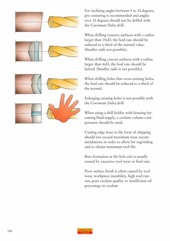
For inclining angles between 5 to 10 degrees, pre-centering is recommended and angles over 10 degrees should not be drilled with the Coromant Delta drill.
When drilling concave surfaces with a radius larger than 15xD, the feed rate should be reduced to a third of the normal value. (Smaller radii not possible). When drilling convex surfaces with a radius larger than 4xD, the feed rate should be halved. (Smaller radii is not possible).
When drilling holes that cross existing holes, the feed rate should be reduced to a third of the normal.
Enlarging existing holes is not possible with the Coromant Delta drill.
When using a drill holder with housing for cutting fluid supply, a coolant volume com-pensator should be used.
Cutting edge wear in the form of chipping should not exceed maximum wear recom-mendations in order to allow for regrinding and to obtain maximum tool-life.
Burr formation at the hole exit is usually caused by excessive tool wear or feed rate.
Poor surface finish is often caused by tool wear, workpiece instability, high tool run-out, poor coolant quality or insufficient oil percentage in coolant.

125
Reconditioning of CoroDrill® Delta-C and Coromant Delta® drills
Additional drill tool-life, of between 3 to 10 times, can be added by regrinding and re-coating.
It is important to follow the specific instruc-tions so that the original geometry is retained to provide the right performance. Therefore regrinding manuals and software for the most common CNC-grinding machines are available. The grinding machine must have 5 axis.
For reconditioning to the original tool-point geometry, the wear before regrinding must not exceed the maximum indicated in the recom-mendations. Since the coating disappears when regrinding the flank, wear resistance will be reduced therefore recoating is always recommended.
Contact your Sandvik Coromant representative for more information about the reconditioning service available.

126

127
For hole diameter and depth, there are extensive application possibilities with tools suited to finishing and roughing operations of small to very large holes and shallow to relatively deep holes. The smallest diameters, starting at 3 mm are bored with fine boring heads holding a boring bar. The largest holes, of up to 975 mm, are finish-bored with a single-edge tool having an adjustable exten-sion-slide mounted on a long concentric or eccentric radial bar. The application of tools for single multi-edge or for step-boring types of operations is very much down to tool-capability and hole-requirement where roughing tools are normally multi-edge and finishing are single-edge.
Four times the hole diameter is generally the maximum recommended depth for boring holes with rotating boring tools where there are individual maximum hole depths for each tool. When it comes to deeper holes, (6xD5m) damped boring tools with tuned tool-bodies should be employed.
Tools developed for finishing have adjust-ment possibilities to accurately pre-set cutting edges, but a boring tool designed for roughing can also be used to achieve holes with a high surface finish and to within close tolerances, as only one of the inserts gene-rates the surface.
Boring tools for roughing, with more than one cutting edge, have relatively simple adjustment possibilities for use in a tool pre-setting facility, but with modern boring tools, such as CoroBore 820, also being possible to set using Vernier calipers.
Application of boring tools – rotating tools

128
Rotating boring tools are equipped with different types of insert carriers. These are dedicated to the type of tool (slides, cartrid-ges, boring bars and fine boring units). Fine-boring units are used in special tool solutions and can be mounted in blind holes without the need for locking after setting. The mechanism of CoroBore 825 can also be used for special tool solutions. It is more rigid than the fine boring unit but does require access from the back of the tool and for the mechanism to be locked when setting is completed.
Generally, a flexible boring tool is the best solution for operations in small to medium batches, with the key features being high penetration rate with high versatility and one tool being used for several hole diameters. A dedicated tool is suited for large-volume machining.
Application points for boring operations with these tools include considering some of the basic and main factors as regards tool-type, method and values:
• Boring tool type and operation method• Tool overhang and diameter of tool• Cutting data and chip control• Insert nose radius, grade and geometry• Cutting fluid - type and application• Damped tools – need for• Tool coupling - suitability• Reaming – suitability and hole preparation.
129
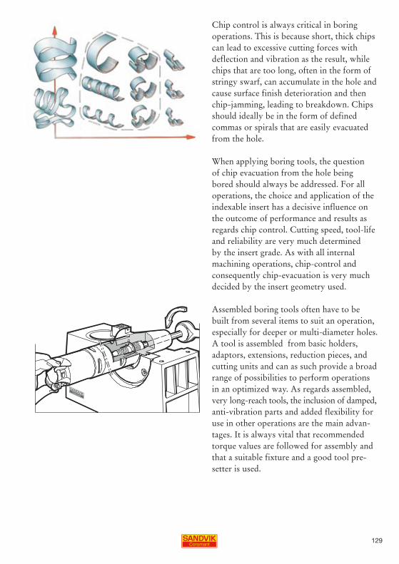
Chip control is always critical in boring operations. This is because short, thick chips can lead to excessive cutting forces with deflection and vibration as the result, while chips that are too long, often in the form of stringy swarf, can accumulate in the hole and cause surface finish deterioration and then chip-jamming, leading to breakdown. Chips should ideally be in the form of defined commas or spirals that are easily evacuated from the hole.
When applying boring tools, the question of chip evacuation from the hole being bored should always be addressed. For all operations, the choice and application of the indexable insert has a decisive influence on the outcome of performance and results as regards chip control. Cutting speed, tool-life and reliability are very much determined by the insert grade. As with all internal machining operations, chip-control and consequently chip-evacuation is very much decided by the insert geometry used. Assembled boring tools often have to be built from several items to suit an operation, especially for deeper or multi-diameter holes. A tool is assembled from basic holders, adaptors, extensions, reduction pieces, and cutting units and can as such provide a broad range of possibilities to perform operations in an optimized way. As regards assembled, very long-reach tools, the inclusion of damped, anti-vibration parts and added flexibility for use in other operations are the main advan-tages. It is always vital that recommended torque values are followed for assembly and that a suitable fixture and a good tool pre-setter is used.
1�0
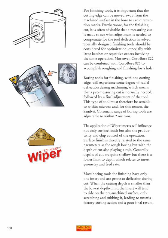
For finishing tools, it is important that the cutting edge can be moved away from the machined surface in the bore to avoid retrac-tion marks. Furthermore, for the finishing cut, it is often advisable that a measuring cut is made to see what adjustment is needed to compensate for the tool deflection involved. Specially designed finishing tools should be considered for optimization, especially with large batches or repetitive orders involving the same operation. Moreover, CoroBore 820 can be combined with CoroBore 825 to accomplish roughing and finishing for a hole.
Boring tools for finishing, with one cutting edge, will experience some degree of radial deflection during machining, which means that a pre-measuring cut is normally needed, followed by a final adjustment of the tool. This type of tool must therefore be settable to within microns and, for this reason, the Sandvik Coromant range of boring tools are adjustable to within 2 microns.
The application of Wiper inserts will influence not only surface finish but also the produc-tivity and chip control of the operation. Surface finish is directly related to the same parameters as for rough boring but with the depth of cut also playing a role. Generally depths of cut are quite shallow but there is a lower limit to depth which relates to insert geometry and feed rate.
Most boring tools for finishing have only one insert and are prone to deflection during cut. When the cutting depth is smaller than the lowest depth-limit, the insert will tend to ride on the pre-machined surface, only scratching and rubbing it, leading to unsatis-factory cutting action and a poor final result.

1�1
Adaptor• Choose shortest possible adaptor - every millimetre is important.
• Choose largest possible diameter/size of adaptor.
• For long overhangs (larger than 4xD) use damped adaptors - Silent Tools.
• If possible, use a tapered adaptor to increase the static stiffness and to reduce the deflection.
• For long overhangs, ensure rigid clamping with flange contact to spindle.
Inserts• Choose a light cutting insert with a positive cutting geometry. Knife-edge inserts are first choice.
• Choose a small nose radius. For finish boring, the recommended nose radius is 0.2 mm. Do not use larger nose radius than 0.4 mm. Try to choose a nose radius which is smaller than the depth of cut.
• Use sharp inserts with relatively thin coatings. Try an uncoated insert as they have sharper cutting edges.
• Triangular-shaped inserts (T-style) are first choice for boring operations
Practical advice on how to reduce vibration tendencies in Boring

1�2
Entering angle• The entering angle should be close to 90 deg. This will give more axial cutting forces and less radial/tangential forces.
Depth of cut• Do not exceed half the cutting edge length when rough boring as this will result in excessive cutting-force load on the cutting edge. When finish boring, the cutting depth is small, typically smaller than 0.5 mm.
Tolerance of hole diameter.• For finishing with one insert, a tolerance of IT7 can be achived in good machining conditions.
• Tolerances will be influenced by the clamping of the tool holder, the fixture of the component and wear of the inserts etc.
• It is recommended that a measuring cut is made. This is to assess what adjustment is needed to compansate for any tool deflection.
• To achieve good surface finish and close tolerances it is important to use cutting fluid. Cutting fluid will prevent recutting of chips and prevent heat-expansion of the tool and workpiece.
Tools for different operationsThere are several options for rough and finishboring.For roughing operations use Duobore with two inserts or CoroBore 820 with three inserts. For overhangs of more than 4xD, a damped Duobore adapter should be used for the best productivity.For finishing operations use a single-edge fine boring tool or CoroBore 825 with one insert.

1��
Step boringIn rough boring operations with two or more inserts, step boring is an effective way to increase the depth of cut without excessive vibrations. Step boring involves having inserts set to different radial and axial dis-tances achieved by using shims in the tool.
Summary - vibration tendencies Vibrations are easily generated when tools are used with long overhangs but there are ways to counter these tendencies:• Use the largest tool-diameter possible.
• Use shortest tool over-hang possible.
• Use tapered shanks/reductions whenever possible.
• Use dedicated tools for longer overhangs
• Silent Tools.
• Check machine spindle, run out, wear, clamping force etc…
• Check that all units in the tool assembly are assembled correctly with the correct torque.
• Reduce cutting speed.
• Reduce feed or increase feed.
• Increase depth of cut (finishing), (decrease in roughing).
• Use smaller nose radius (finishing).
• Use inserts with sharper cutting edge.
• Use 90 entering angle (roughing).
• Check workpiece clamping.

1�4
ap<rε ap=rε ap>rε∆R
ap
FC [N] FC [N] FC [N]
apap
aprε rε rε
Reasons for vibration tendencies at the cutting zone are usually : insert geometry too negative, unsuitable entering angle or excessive nose radius. Generally, the cutting edge should always cut as easily, with inserts having a very positive top rake, sharp cutting edge and small nose radii, with the entering angle as close to 90 degrees as possible. The CoroTurn 107 insert meets these require-ments and is recommended as first choice for many boring operations.
The radial cutting forces are related to the size of the nose radius of the insert and con-sequently the vibration tendencies. A large nose radius will tend to deflect a boring bar more than a smaller nose radius and make it more susceptible to vibrations. Recommended nose radius is 0.2 mm. Do not use a nose radius larger than 0.4 mm for finish boring. For roughing, larger nose radii are recommended.
Silent Tools should always be used when the tool overhang exceeds 4xD and here the first choice as regards indexable inserts should be: • Knife-edge inserts.• Entering angle 90 degrees and 92 degrees for finishing.
When using damped tools in assemblies, care should be taken so as to hold the tool bodies correctly to make sure that the adaptors are not damaged, thereby rendering it ineffec-tive. These are easily deformed due to the thin wall thicknesses. Correct assembly units should be used.
1�5
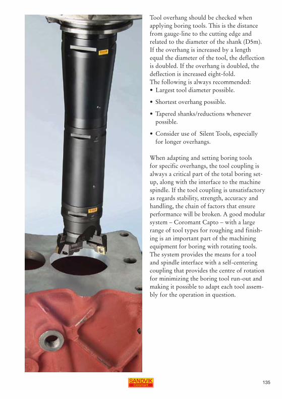
Tool overhang should be checked when applying boring tools. This is the distance from gauge-line to the cutting edge and related to the diameter of the shank (D5m). If the overhang is increased by a length equal the diameter of the tool, the deflection is doubled. If the overhang is doubled, the deflection is increased eight-fold. The following is always recommended:• Largest tool diameter possible.
• Shortest overhang possible.
• Tapered shanks/reductions whenever possible.
• Consider use of Silent Tools, especially for longer overhangs.
When adapting and setting boring tools for specific overhangs, the tool coupling is always a critical part of the total boring set-up, along with the interface to the machine spindle. If the tool coupling is unsatisfactory as regards stability, strength, accuracy and handling, the chain of factors that ensure performance will be broken. A good modular system – Coromant Capto – with a large range of tool types for roughing and finish-ing is an important part of the machining equipment for boring with rotating tools. The system provides the means for a tool and spindle interface with a self-centering coupling that provides the centre of rotation for minimizing the boring tool run-out and making it possible to adapt each tool assem-bly for the operation in question.

1�6
Application of cutting data For roughing operations,to start with, the cutting speed should be reduced by about 50 % in order to check on that proper chip-evacuation takes place. Rough boring, particularly when using three cutting edges, generates as a lot of chips and these must be transported out of the hole efficiently. The maximum cutting speed is not so much limited by tool-life as vibration tendencies.
For finishing operations, the required surface finish often puts limitations on the maximum feed for any given nose radius. Changes here to influence chipform are therefore limited. However, the chips generated must have a suitable form to be evacuted without dam-aging the surface of the hole and the choice and application of insert, therefore, becomes very important. By using a Wiper insert, the surface finish can be dramatically improved using the same feed. However, the Wiper inserts do need good stability as they exert more radial pressure which may increase the risk of vibration.
When finish boring the maximum depth of cut is not so much related to the size of the insert as the type of insert-geometry. The recommended inserts and geometries for finish boring are designed to work at small depths of cut. When excessive depths of cut used, the chips can jam between workpiece and tool, causing the cutting edge to break. Maximum depth of cut in roughing should not exceed half the cutting edge length.
As one chip-formation factor, the depth of cut is determined by the recommended values for each insert geometry. The sharper a geometry is, and the smaller the nose radius, the smaller the depth of cut possible. It may very well be that an increase in depth of cut may lead to harder chipbreaking,

1�7
while a reduction may lead to insufficient cutting edge engagement, with rubbing as a result. If chips are generated sporadically during machining, the depth of cut may be insufficient or excessive.
Coolant should be used when finish boring, especially to close tolerances and to achieve very good surface finishes. It is vital to evacuate chips quickly away from the cutting zone and out of the bore. Coolant also limits the heat-expansion of workpiece and tool.
ReamingFor reaming operations to very close tole-ranceas and surface finishes, the Reamer 830 is very effective with high operational secu-rity and a basic factor for good reaming perfomance generally is the quality of the hole to be reamed. Reaming should not be expected to correct any locational or straigh-ness errors of the pre-machined hole.
A few application hints help to ensure successful results:• Straightness of pre-machined holes should be within 0.01 mm.
• Radial depth of cut (ap) should be 0.1 mm or more.
• The feed rate should be above 0.1 mm/ tooth.
• Emulsion as cutting fluid is better than oil due to the cooling properties.
• A cutting fluid pressure of 4 bars is sufficient.
• Minimal lubrication techniques can be used.
• Vibrations at hole entry can be reduced by increased feed and/or a slight honing of the cutting edges.
• The tool holding should be of good quality, such CoroGrip or HydroGrip precision chucks.

1�8

1�9
Circular interpolation - instead of boringMachining of existing holes can be per-formed with circular interpolation. It is an internal (or external) 2-axis operation mainly used for : opening up, finishing, providing a chamfer or as part of a back-facing operation on holes.
Circular interpolation Machining of existing holes following a circular tool-path without any axial movement. Down-milling is the preferred milling method for internal circu-lar interpolation and the right value for the maximum radial depth of cut is important for both circular and helical interpolation.Roughing operations involving somewhat deeper holes are machined efficiently in this way using an indexable insert long-edge cutter (CoroMill 390), where where part or whole combined cutting edge can be used. Finishing and lighter cuts of shorter lengths can be performed with an indexable insert square shoulder facemill or endmill (CoroMill 390) as well as with a solid car-bide endmill (CoroMill Plura) with a longer peripheral cutting edge.
Application of milling tools

140
Helical interpolation - instead of drillingMaking new holes can be achieved through helical interpolation. (Spiral or orbital drilling is another name of this type of machining). It is the main method for making round holes by way of milling. Being a 3-axis operation, it involves a ramping operation in combination with the circular interpolation and is ideally performed with a suitable endmill (CoroMill 390), round insert cutter (CoroMill 300) or solid carbide endmill (CoroMill Plura).
Helical interpolation may also be suitable to machine exisiting holes and can also be used to straighten holes. It is also widely used to start making pockets, which are then machined radially with the same endmill. Helical interpolation is similar to that of thread-milling.
The choice of making a hole through inter-polation instead of drilling depends upon a few factors. Drilling is very efficient when it comes to volume-drilling of holes. The main factors that may point to helical interpola-tion instead of drilling are power and torque availability in machines. These can be the limiting factors, especially for larger hole-diameters. Helical interpolation is then often a more advantageous method compared to drilling followed by one or more boring operations.

141
Other factors include making one-off holes or or a large variety of hole sizes in small batches. In mixed production, on a modern machining centre, or when very large holes are made in boring mills, helical interpolation with a milling cutter may often be competive.
Chip-evacuation problems or chipbreaking can in some cases influence the choice of method as can a large variation of hole-sizes or the occasional need to make certain holes. There may be a need for limiting the number of tools in set-ups and magazines, as well as performing roughing and finishing opera-tions with one tool, which may not warrant including a drill.
An important point to observe with hole making from solid through helical interpola-tion milling is establishing the right tool-type, tool-diameter and cutting data in rela-tion to the hole to be machined.
A varity of hole sizes and small batches.Roughing and finishing with one tool.Limited No of free tool space in the magazine.
Large holes in a small machine.
Milling holes is an option to drilling when chipcontrol is a problem.

142
The run-out of the milling cutter involved should be minimized as should the play in the spindle, table, etc for smooth changes of direction of the milling cutter in the process and especially when a reasonable finish is required,
As regards the machine, satisfactory control at high feed rates and good look-ahead func-tion are properties which are advantageous for helical interpolation. The roundness of the hole is fully dependant on the accuracy of the machine tool. Any play along the axes of the machine will influence the level of roundness.
Excessive feed-per-tooth rates or max. chip thicknesses often have a negative effect on the surface finish in the process. On the other hand, small max. chip-thickness (hex) values will need sharp cutting edges for satisfactory edge-engagement and to achieve good surface finishes (PVD-coated endmills/inserts).
Generally, the feed-per-tooth or max. chip thickness for the cutter should always be calculated and checked in relation to the maximum radial depth of cut involved. Recommended feed values vary with insert sizes.
ap
Dc
De

14�
For helical and circular interpolation, the feed value to use in the software program for the machine varies for different types of soft-ware. The centre table-feed (vf) or feed at the tool centre-line is the most common while the peripheral table-feed (vfm) or feed at the cutting edge is another common input. A feed-value, expressed in degrees-per-minute or rpm of the workpiece, can also be calcu-lated and is useful for 5-axis machining and in multi-task machines. There is also the axial feed (vfa) or the rate of ramping usually cal-culated when comparing to other methods. A simplified version instead of calculating the radial depth (ae) and feed per insert (fz) is available by using a factor (K) which takes into account the relationship between tool- and hole-diameters. These circular values are then combined with the relevant ramping values for helical interpolation milling. The max. pitch of the helical feed (ap) is calcu-lated using the max. ramping angle (α) and the length of one revolution the peripheral table-feed (Dvf).
(Assistance for accurate calculations is given in the chapter 5 .)
vf = n × z × n
vfm = vf × K
fz = Dm - Dc
Dm
ap = Dvf × tan α
Dc
D3

144
Rough machining new holes or cavities and shoulders can be performed efficiently through plunge milling. This is identical to plunge drilling but uses positive milling tools such as indexable insert endmill (CoroMill 390) or round insert cutter (CoroMill 300) or solid carbide endmill (CoroMill Plura). The cutter is repeatedly plunged to a certain depth at a certain step-over entailing axial feeding and cutting with the end cutting edges of the tool.
Rigidity of tool, tool holding and spindle is not as critical as the main cutting force is along the axial z-axis. Consequently, longer tool overhangs and more unstable machining conditions can be tolerated because of the very small radial forces. Milling cutters with an overhang of four times the tool diameter or considerably more are often advanta-geously used in plunge milling.
An added advantage is that demanding- to-machine materials can be machined very efficiently by plunge milling. A typical example is that of titanium components where a lot of material has to be removed to make holes, cavities and shoulders. Another is in die and mould making where holes and cavities in some form are part of almost every component. When plunging corners of cavities, the problem caused by large engage-ments of the milling cutter in corner should be addressed. Longer tool-life is normally a bonus with plunge milling as the cutting edges are not subjected to the same wear as in radial milling. Chip evacuation is normally quite good with the process and can be assisted by using compressed air, especially in vertical machines.
Generally, in addition to the above conside-rations, plunge milling should be considered when long axial tool-engagements are involved, when metal removal rates are a priority and when the process is advantageous from an accessibility point of view.
Plunge milling
<6 × Dc

145
iC
9 8 14 13 <0.75 × D3
ae
s
Less power and torque is needed to plunge mill and a machine tool lacking in stability, having a weak spindle and limited spindle speed can with advantage accomodate the process. Also unstable workpieces and flimsy set-ups are less problematic with plunge milling. The process also allows good cove-rage of workpiece-area through extensive reach especially on horizontal machines.
An initial hole for the milling cutter to access the workpiece is required for the plunge milling process to be able to start. This can with advantage be made by a somewhat larger indexable insert drill. Commence plunge milling by keeping the cutter engaged according to the max. step-over value. Then use a high feed-rate retract instead of a rapid transit-move in the cycle but start by retrac-ting a couple of mm at a 45 degree angle.
Step-over values for plunge milling are recommended for each tool-type and size. For example, for the CoroMill® 390 endmill, step-over values in the region of half the insert cutting edge length are suitable. With the round insert CoroMill® 300 cutter, step-over values of 0.75 x the insert diameter (IC) are possible.
Also the axial feed rates are recommended according to insert size. Feed per tooth values should be fine, in the region of 0.05 to 0.10 mm/tooth. Cutting speeds are nor-mal, as for conventional endmilling. For the CoroMill® 390 endmill, ground E-tolerance inserts often provide the best performance and inserts having a nose radius of 1.2 mm are best suited to help minimize any radial deflection of the tool.
max recom-mended ae, mm
max recom-mended s

146
Plunge drilling can be performed with a standard indexable insert drill, CoroDrill 880, with depths to three times the diameter. For depths to six times the diameter, the dedi-cated plunge drill Coromant U (416.22) is ideal. The drills are centre cutting with two inserts and generally a superior plunging method as regards productivity. Well over half of the drill diameter (70%) can be applied as the step-over (the next over-lapping cut) using the plunge drill at full indexable insert drill cutting data. This means that metal removal rate is very high.
Plunge milling is the similar to plunge drilling using the positive indexable insert endmill CoroMill 390, round insert cutter CoroMill 300 or solid carbide endmill CoroMill Plura, depending upon the applica-tion. Also the high-feed milling CoroMill 210 is suitable for many applications. But a milling cutter, which is not centre cutting, has a much more limited step-over – only up to half of the axial insert cutting edge length. For this reason, it only becomes interesting from a productivity point of view when diameters are large enough to provide a sufficient number of teeth in engagement to enable high feed rates. It is also seen as an alternative to shoulder milling when long tool overhangs are involved.
When to plunge drill or plunge mill

147
Advantages of plunging include that rigidity of tool, tool holding and spindle is not as critical as it is in radial machining. The main cutting force is directed along the axial z-axis and longer tool overhangs and more unstable machining conditions are possible because of the small radial forces. There is also often a possibility to use a more wear resistant grade in plunging, and thus higher cutting data, than would normally have been the case in hole machining with long overhangs, because cutting-edge toughness is often a require-ment to counter the effect of vibration ten-dencies. Tools with an overhang of several times the diameter can be accommodated without problems and the deeper the cavity, the more advantageous is plunging.
Demanding-to-machine materials can be machined very efficiently through plunging and often without some of the typical cutting edge wear. Titanium components where a lot of material has to be removed to make holes, cavities and shoulders are ideal applications. Also in die and mould making, holes and cavities appear in some form as part of every component. When machining corners of cavities, the problem caused by large radial engagements of the milling cutter can be solved through plunging. When machining cavity corners, rest-machining of corners can be eliminated or facilitated through plunging operations.
Lower power, torque and stability of machines can also be a reason for adopting plunge drilling and milling. Less is needed compared to comparable radial milling and a machine tool lacking in stability, having a weak spindle and limited spindle speed can with advantage accomodate the process. Also radially unstable workpieces, fixtures and flimsy set-ups are less of a problem with plunging.

148
An initial drilled hole for the plunge tool to access the workpiece is required for the plunging process to be able to start. In plunge milling, a drilling CNC-cycle should be avoided, especially when it comes to retracting the tool. Several initially-drilled holes should also be considered, leaving less material to be machined by plunging. Cavities to be plunge drilled should be started off using an ordinary indexable drill to make one or several initial holes, where drilling needs to be optimized as regards the number and positons of initial holes.
Solid drilling with the dedicated plunge drill (416.22) is possible to a depth equalling the drill-diameter – but never beyond, because of the short chip evacuation channel. The plunge drill is centre-cutting but has no capability to evacuate chips at any greater depths of full drilling. This is due to the design for high stability for actual plunge drilling, while also making it suitable for helical interpolation. Overlapping holes can be machined to a depth of 6xD in both through- and blind-holes and two-axis machining can be performed with a tool engagement of less than 50% of the diameter.
Step-over values for plunge milling are recommended for each milling tool type and size. For example, for the CoroMill 390 endmill values in the region of half the insert cutting edge length are suitable. With the round insert CoroMill 300 cutter, step-over values of 0.80 x the insert diameter (IC) are possible. The axial feed rates are also recom-mended according to insert size. Feed per tooth values should be fine, in the region of 0.05 to 0.10 mm/tooth. Cutting speeds are normal for the chosen insert grade, as for conventional endmilling. A somewhat larger nose radius should be chose to give added strength to the insert corner.

149
Plunge drilling is the most efficient method for tool diameters up to about 35 mm. For large diameters, plunge milling is normally more advantageous when performed with suitable endmills, round insert cutters or dedicated high-feed milling cutters. The engagement of more teeth provides better efficiency in the form of higher feed rates, even though the smaller step-over rate is a limitation. The shape of the cavity should also influence the choice of method.
Optimum plunging efficiency in plunge drill-ing is usually achieved with the maximum step-over, which is 70% of the drill diameter. This is especially the case when plunging series of four holes and it also ensures that a material-core is not left in the hole. A step-over of 50% should be avoided as regards cutting edge strength and vibration tenden-cies because of cutting edge engagement.
Blind holes and semi-blind holes means that chip evacuation is a critical factor. Plunging is a fast metal-removal method and produces large amounts of chips very quickly. These need to be removed efficiently from the machining zone to prevent the re-cutting of chips or chip congestion. Chip evacuation should be assisted by using well-applied, high-pressure compressed air when milling - especially in vertical machines. If coolant is used, the highest pressure and volume should be applied. For instance, two holes can be drilled followed by plunging inbetween, leaving plenty of space for chips to be evacu-ated – again as part of establishing the hole size and positioning to provide optimum cavity-making efficiency.
Only internal coolant-supply should be used for plunge drilling to ensure sufficient evacuation flow – this is especially important for vertical machines.

150
The tool systemHowever good the drill, boring tool, reamer or milling cutter, if the tool-holding interface with machine spindle and turret is unsatisfac-tory, performance, reliability and quality will not be as good as it can be. Holding, chang-ing, storing, handling and administrating tools are critical links in the chain that sup-ports successful hole making.
The ability to securely and accurately clamp and present tools for a machining opera-tion is decisive, not only for achieving the desired component quality and tool-life, but also for performing roughing operations productively. In times when spindle speeds are continually elevated towards high speed machining and new machining methods are being introduced, the quality of clamping a solid carbide drill or milling cutter as well as indexable insert drill or endmill will in many cases make the difference between competi-tive and uncompetitive machining.
Coromant Capto is the only modular tooling system designed for all metal cutting opera-tions without compromise – including all hole making methods. The same cutting tools and adaptors can be used in different applications and machines. This makes it possible to standardize on one tooling sys-tem for the entire machine shop. There are many possibilities of assembling tools with a variety of lengths and design characteristics. Furthermore, the same system can also be installed in various machines types in diffe-rent ways.
Tool holding for hole making

151
CoroGrip®
HydroGrip
Tool chucks for hole makingIncorporated in tooling systems – and critical for performance - are tool chucks. CoroGrip and HydroGrip are high-strength, precision chucks for holding drills and endmills. Characterized by clamping strength, accu-racy and stability the CoroGrip chuck uses hydraulic pressure to actuate the mechanical clamping function, thereby providing the unique tool holding capability. The HydroGrip chuck uses hydraulics as the clamping means. These features provide the cutting tools with the basis needed for good machining.
As sufficient stability is a pre-condition of any machining operation, these chucks provide a reliable basis for continued optimization. To maintain precision in a machining opera-tion with rotating tools, factors such as radial run-out, bending strength, torque transmis-sion and even balance for high spindle speeds have to be addressed. There are several tool holding methods that have been developed through the years, involving various collet chucks, hydraulic chucks, shrink fit holders, etc. and all have advantages and disadvan-tages. The CoroGrip and HydroGrip chucks have been developed so as to provide an improvement on what these methods have to offer. Providing tools with optimum stability by being as close to the spindle interface as possible is often a determining quality and reliability factor, as is the ability to provide high stability of long-reach tools into or past components being machined.

152
Minimizing run-outTool-life of cutting tools is, in most cases, directly related to the amount of run-out of cutting edges in relation to the centre-line of rotation. A run-out of hundredths of a mm has a profound effect on how cutting edges will last in many operations, especially in finishing using solid cemended carbide tools. The level of precision in tool holding is therefore often critical, not only to the resulting component quality, but also the predictability and reliability of tool performance.
High clamping forces in tool-holding deter-mine how secure the cutting tool is held and torque transmitted during machining. As cutting forces act on the tool, the tool will tend to slip in the holder. The capability of the tool holder can then be related to how tight the tool-shank is clamped. As spindle speeds become higher, balancing becomes a factor growing in importance. Centrifugal forces will act on tool holder and cutting tool, trying to make use of any imbalance to create vibrations
As a further step, when using demanding cutting data in an operation involving a tool chuck, it is recommended to consider the option of using a larger chuck that will allow the use of a collet. The larger chuck with collet will improve stability considerably increase the clamping power on the tool shank. The clamping power of the chuck is applied on a larger area than that of the inner diameter of the collet and this provides an increase per area-unit on the shank of the tool.

15�
Programming sequence when using Sandvik coromant back chamfering tools
One ofter time consuming operation is de-burring of drilled holes. This operation is typically performed off the machine tool by skilled operators. This method of removing burrs creates many problems including –• Time consuming – up to 20 hours to de-burr a typical casing.
• No repeatability – Operator dependent.
• Surface integrity – Uncontrolled effect on the surface of the component.
• Health and Safety – Vibrating tools are commonly used increasing the risk.
By using a coromant XS de-burring tool it is possible to increase productivity while pro-viding a repeatable, mechanised, safe process.Minimum hole size – 7mm.
Back chamfering/de-burring

154
Silent Tools are tools developed to counter limitations in machining from vibration tendencies. As tool holders and adaptors for internal turning, boring with rotating tools, milling and drilling, they provide the means to maintain productivity and hole quality levels that would otherwise have been compromised.
When increasing the tool overhang to reach into deeper holes (4–6 times the diameter depending upon the type of maching), tool deflection, cutting forces and machining stability are the main risk factors that have to be addressed.
To counter deflection, high static stiffness as well as dynamic stiffnes of the set-up is vital, as are the smallest possible and correctly directed cutting forces.
High tool holding stability is absolutely essential through good clamping rigidity- the set-up is only as strong as its weakest link, The overhang of the tool affects the size of deflection by the power of three. The size of the tool diameter affects the deflection by the power of two.
The static stiffness can be improved by making sure that the best possible tool dia-meter and overhang ratio is used and that the best tool shape and possible reinforcement is considered.
The dynamic stiffness can be improved by using the lightest possible tool unit at the end of the bar or adaptor and using a damped tool or adaptor. Also maximising the static stiffness will improve the dynamic stiffness.
Silent Tools – machining deeper holes
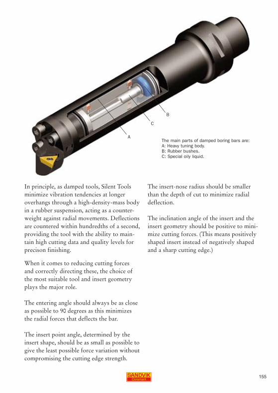
155
B
C
A
In principle, as damped tools, Silent Tools minimize vibration tendencies at longer overhangs through a high-density-mass body in a rubber suspension, acting as a counter-weight against radial movements. Deflections are countered within hundredths of a second, providing the tool with the ability to main-tain high cutting data and quality levels for precison finishing.
When it comes to reducing cutting forces and correctly directing these, the choice of the most suitable tool and insert geometry plays the major role.
The entering angle should always be as close as possible to 90 degrees as this minimizes the radial forces that deflects the bar.
The insert point angle, determined by the insert shape, should be as small as possible to give the least possible force variation without compromising the cutting edge strength.
The insert-nose radius should be smaller than the depth of cut to minimize radial deflection.
The inclination angle of the insert and the insert geometry should be positive to mini-mize cutting forces. (This means positively shaped insert instead of negatively shaped and a sharp cutting edge.)
The main parts of damped boring bars are: A: Heavy tuning body. B: Rubber bushes. C: Special oily liquid.