Embed Size (px)
Citation preview

SANnet II® 200 FC and SATA ArrayBest Practices Manual
July 200583-00003263, Revision C

CopyrightCopyright 2001-2005 Dot Hill Systems Corp. All rights reserved. No part of this publication may be reproduced, stored in a retrieval system, translated, transcribed, or transmitted, in any form or by any means – manual, electric, electronic, electromechanical, chemical, optical, or otherwise – without prior explicit written permission of Dot Hill Systems Corp., 6305 El Camino Real, P.O. Box 9000, Carlsbad, CA., 92009-1606.
TrademarksDot Hill Systems, the Dot Hill logo, SANscape, SANnet, and SANpath are registered trademarks of Dot Hill Systems Corp. All other trademarks and registered trademarks are proprietary to their respective owners.
ChangesThe material in this document is for information only and is subject to change without notice. While reasonable efforts have been made in the preparation of this document to assure its accuracy, Dot Hill Systems Corp., assumes no liability resulting from errors or omissions in this document, or from the use of the information contained herein. Dot Hill Systems Corp., reserves the right to make changes in the product design without reservation and without notification to its users.
Contents
Preface . . . . . . . . . . . . . . . . . . . . . . . . . . . . . . . . . . . . . . . . . . . . . . . . . . . . xi
1. Overview . . . . . . . . . . . . . . . . . . . . . . . . . . . . . . . . . . . . . . . . . . . . . . . . . . . . 1
2. Underlying Concepts and Practices . . . . . . . . . . . . . . . . . . . . . . . . . . . . . . 3
Fibre Channel Protocols . . . . . . . . . . . . . . . . . . . . . . . . . . . . . . . . . . . . . . . . . 3
Supported RAID Levels . . . . . . . . . . . . . . . . . . . . . . . . . . . . . . . . . . . . . . . . . 4
Logical Drives . . . . . . . . . . . . . . . . . . . . . . . . . . . . . . . . . . . . . . . . . . . . . . . . 4
Maximum Drive Configurations per Array . . . . . . . . . . . . . . . . . . . . . . . . . . . . 5
Maximum Number of Disks and Maximum Usable Capacity per Logical Drive 6
Cache Optimization . . . . . . . . . . . . . . . . . . . . . . . . . . . . . . . . . . . . . . . . . . . . 8
Configuring an Array’s RCCOM Channel . . . . . . . . . . . . . . . . . . . . . . . . . . . . 9
Using Four DRV + RCCOM Channels . . . . . . . . . . . . . . . . . . . . . . . . . . . 9
Using Channels 4 and 5 as RCCOM Channels . . . . . . . . . . . . . . . . . . . 10
Array Management Tools . . . . . . . . . . . . . . . . . . . . . . . . . . . . . . . . . . . . . . . 10
Saving and Restoring Configuration Information . . . . . . . . . . . . . . . . . . . . . 11
3. Planning Your Storage Architecture . . . . . . . . . . . . . . . . . . . . . . . . . . . . . 13
Direct-Attached Storage . . . . . . . . . . . . . . . . . . . . . . . . . . . . . . . . . . . . . . . . 14
Storage Area Networking . . . . . . . . . . . . . . . . . . . . . . . . . . . . . . . . . . . . . . . 15
Scaling Capacity . . . . . . . . . . . . . . . . . . . . . . . . . . . . . . . . . . . . . . . . . . . . . 16
First Steps in Designing a Solution . . . . . . . . . . . . . . . . . . . . . . . . . . . . . . . 17
Designing a Storage Solution for an Existing Environment . . . . . . . . . . 17
Designing a New Storage Solution . . . . . . . . . . . . . . . . . . . . . . . . . . . . . 17
General Configuration Considerations . . . . . . . . . . . . . . . . . . . . . . . . . . 18
iii
4. DAS Configurations . . . . . . . . . . . . . . . . . . . . . . . . . . . . . . . . . . . . . . . . . .21
Single-Controller DAS Configurations . . . . . . . . . . . . . . . . . . . . . . . . . . . . .21
Single-Controller DAS Tips and Techniques . . . . . . . . . . . . . . . . . . . . . .22
Single-Controller DAS Setup Details . . . . . . . . . . . . . . . . . . . . . . . . . . .23
Dual-Controller Multipath DAS Configurations . . . . . . . . . . . . . . . . . . . . . . .25
Dual-Controller Multipath DAS Tips and Techniques . . . . . . . . . . . . . . .25
Sample Dual-Controller Multipath DAS Setup Details . . . . . . . . . . . . . .26
5. SAN Configurations . . . . . . . . . . . . . . . . . . . . . . . . . . . . . . . . . . . . . . . . . .29
Full-Duplex SAN Configurations . . . . . . . . . . . . . . . . . . . . . . . . . . . . . . . . . .29
Full-Duplex SAN Tips and Techniques . . . . . . . . . . . . . . . . . . . . . . . . . .30
Sample Full-Duplex SAN Setup Details . . . . . . . . . . . . . . . . . . . . . . . . .30
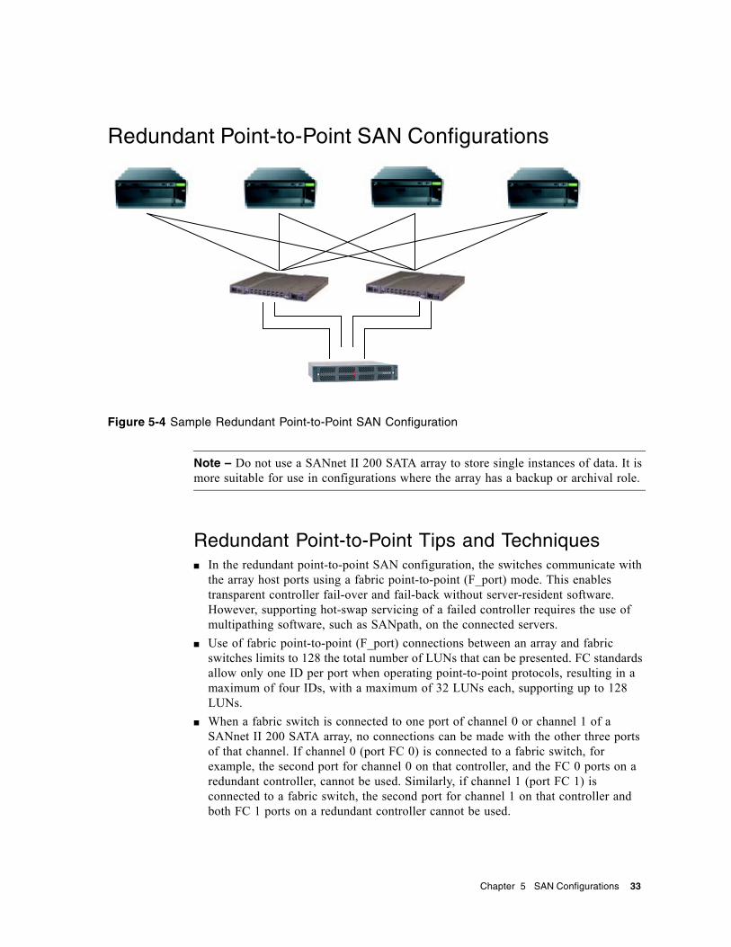
Redundant Point-to-Point SAN Configurations . . . . . . . . . . . . . . . . . . . . . . .33
Redundant Point-to-Point Tips and Techniques . . . . . . . . . . . . . . . . . . .33
Redundant Point-to-Point Setup Details . . . . . . . . . . . . . . . . . . . . . . . . .34
6. Using Multiple Expansion Units in High Capacity Configurations . . . . .37
SANnet II 200 FC Array High-Capacity Configurations . . . . . . . . . . . . . . . . .37
Limitations . . . . . . . . . . . . . . . . . . . . . . . . . . . . . . . . . . . . . . . . . . . . . . . . . .38
Connecting One Expansion Unit . . . . . . . . . . . . . . . . . . . . . . . . . . . . . . . . . .38
Connecting Two Expansion Units . . . . . . . . . . . . . . . . . . . . . . . . . . . . . . . . .39
Connecting Three Expansion Units . . . . . . . . . . . . . . . . . . . . . . . . . . . . . . .40
Connecting Four Expansion Units . . . . . . . . . . . . . . . . . . . . . . . . . . . . . . . .41
Connecting Five Expansion Units . . . . . . . . . . . . . . . . . . . . . . . . . . . . . . . . .41
Connecting Six Expansion Units . . . . . . . . . . . . . . . . . . . . . . . . . . . . . . . . .42
Connecting Seven Expansion Units . . . . . . . . . . . . . . . . . . . . . . . . . . . . . . .43
Connecting Eight Expansion Units . . . . . . . . . . . . . . . . . . . . . . . . . . . . . . . .44
7. SANnet II 200 SATA Array High-Capacity Configurations . . . . . . . . . . . .47
Connecting One Expansion Unit . . . . . . . . . . . . . . . . . . . . . . . . . . . . . . . . . .48
Connecting Two Expansion Units . . . . . . . . . . . . . . . . . . . . . . . . . . . . . . . . .49
Connecting Three Expansion Units . . . . . . . . . . . . . . . . . . . . . . . . . . . . . . .50
Connecting Four Expansion Units . . . . . . . . . . . . . . . . . . . . . . . . . . . . . . . .51
iv SANnet II 200 FC and SATA Array Best Practices Manual • July 2005

Connecting Five Expansion Units . . . . . . . . . . . . . . . . . . . . . . . . . . . . . . . . 51
8. Combining SANnet II 200 FC Arrays and SANnet II 200 SATA Expansion Units . . . . . . . . . . . . . . . . . . . . . . . . . . . . . . . . . . . . . . . . . . 53
Restrictions on the Use of Expansion-Unit Combinations . . . . . . . . . . . . . . 53
Connecting Three FC Expansion Units and Two SATA Expansion Units to a SANnet II 200 FC RAID Array . . . . . . . . . . . . . . . . . . . . . . . . . . . . . . . . 54
Contents v

vi SANnet II 200 FC and SATA Array Best Practices Manual • July 2005
Figures
FIGURE 3-1 DAS and SAN Storage Architectures . . . . . . . . . . . . . . . . . . . . . . . . . . . . . . . 13
FIGURE 3-2 Two DAS Configurations . . . . . . . . . . . . . . . . . . . . . . . . . . . . . . . . . . . . . . . . . 14
FIGURE 4-1 Three Single-Controller DAS Configurations . . . . . . . . . . . . . . . . . . . . . . . . . . 22
FIGURE 4-2 Sample Single-Controller SANnet II 200 FC DAS Connections . . . . . . . . . . . 23
FIGURE 4-3 Sample Single-Controller SANnet II 200 SATA DAS Connections . . . . . . . . . 23
FIGURE 4-4 Sample Dual-Controller Multipath DAS Configurations . . . . . . . . . . . . . . . . . . 25
FIGURE 4-5 Sample Dual-Controller Multipath SANnet II 200 DAS Connections . . . . . . . . 26
FIGURE 4-6 Sample Dual-Controller Multipath SANnet II 200 SATA DAS Connections . . 27
FIGURE 5-1 Typical Full-Fabric SAN Configuration . . . . . . . . . . . . . . . . . . . . . . . . . . . . . . 29
FIGURE 5-2 Sample SANnet II 200 FC Full-Duplex SAN Connections . . . . . . . . . . . . . . . . 30
FIGURE 5-3 Sample SANnet II 200 SATA Full-Duplex SAN Connections . . . . . . . . . . . . . 31
FIGURE 5-4 Sample Redundant Point-to-Point SAN Configuration . . . . . . . . . . . . . . . . . . 33
FIGURE 5-5 Sample Redundant Point-to-Point SANnet II 200 FC SAN Connections . . . . 34
FIGURE 5-6 Sample Redundant Point-to-Point SANnet II 200 SATA SAN Connections . . 35
FIGURE 6-1 SANnet II 200 FC Array Configuration with One Expansion Unit . . . . . . . . . . 38
FIGURE 6-2 SANnet II 200 FC Array Configuration with Two Expansion Units . . . . . . . . . 39
FIGURE 6-3 SANnet II 200 FC Array Configuration with Three Expansion Units . . . . . . . . 40
FIGURE 6-4 SANnet II 200 FC Array Configuration with Four Expansion Units . . . . . . . . . 41
FIGURE 6-5 SANnet II 200 FC Array Configuration with Five Expansion Units . . . . . . . . . 42
FIGURE 6-6 SANnet II 200 FC Array Configuration with Six Expansion Units . . . . . . . . . . 43
FIGURE 6-7 SANnet II 200 FC Array Configuration with Seven Expansion Units . . . . . . . . 44
FIGURE 6-8 SANnet II 200 FC Array Configuration with Eight Expansion Units . . . . . . . . . 45
FIGURE 7-1 SANnet II 200 SATA Array Configuration with One Expansion Unit . . . . . . . . 48
FIGURE 7-2 SANnet II 200 SATA Array Configuration with Two Expansion Units . . . . . . . 49
vii
FIGURE 7-3 SANnet II 200 SATA Array Configuration with Three Expansion Units . . . . . .50
FIGURE 7-4 SANnet II 200 SATA Array Configuration with Four Expansion Units . . . . . . .51
FIGURE 7-5 SANnet II 200 SATA Array Configuration with Five Expansion Units . . . . . . .52
FIGURE 8-1 SANnet II 200 FC Array Configuration with Three FC Expansion Units and Two SATA Expansion Units . . . . . . . . . . . . . . . . . . . . . . . . . . . . . . . . . . . . . . .55
viii SANnet II 200 FC and SATA Array Best Practices Manual • July 2005
Tables
TABLE 2-1 Maximum Number of Disks per Logical Drive . . . . . . . . . . . . . . . . . . . . . . . . . . . . 5
TABLE 2-2 Maximum Number of Supported Physical and Logical Drives, Partitions, and LUN Assignments . . . . . . . . . . . . . . . . . . . . . . . . . . . . . . . . . . . . . . . . . . . . . 6
TABLE 2-3 Actual Capacities per Drive . . . . . . . . . . . . . . . . . . . . . . . . . . . . . . . . . . . . . . . . 7
TABLE 2-4 Maximum Usable Storage Capacity Determined by RAID level . . . . . . . . . . . . . . 7
TABLE 2-5 Default Stripe Size Per Optimization Mode (Kbyte) . . . . . . . . . . . . . . . . . . . . . . 9
TABLE 4-1 Sample Setup Summary for Single-Controller DAS Configurations . . . . . . . . 24
TABLE 4-2 Sample Setup Summary for Dual-Controller Multipath SANnet II 200 SATA DAS Configurations . . . . . . . . . . . . . . . . . . . . . . . . . . . . . . . . . . . . . . . 27
TABLE 5-1 Setup Summary for Full Fabric SAN . . . . . . . . . . . . . . . . . . . . . . . . . . . . . . . . 31
TABLE 5-2 Setup Summary for a Redundant Point-to-Point Configuration . . . . . . . . . . . . 35
ix

x SANnet II 200 FC and SATA Array Best Practices Manual • July 2005
Preface
This manual gives an overview of SANnet II 200 FC arrays and SANnet II 200 SATA arrays, and presents several sample storage solutions for entry-level, mid-range, and enterprise servers.
Caution – You should read the SANnet II Family Safety, Regulatory, and Compliance Manual before beginning any procedure in this manual.
How This Book Is OrganizedThis book includes the following topics:
Chapter 1 provides an overview of the SANnet II 200 FC array and SATA array.
Chapter 2 provides an overview of important concepts and practices that underly the configurations you can use.
Chapter 3 helps you determine which direct-attached storage (DAS) and storage area network (SAN) configurations are most appropriate for your requirements.
Chapter 4 presents several sample DAS configurations you can use.
Chapter 5 presents several sample SAN configurations you can use.
Chapter 6 describes high-capacity configurations involving multiple expansion units and presents sample SANnet II 200 FC configurations that maximize reliability, availability, and serviceability (RAS).
Chapter 7 presents sample high-capacity SANnet II 200 SATA configurations that maximize reliability, availability, and serviceability.
Chapter 8 describes a sample high-capacity configuration that includes both SANnet II 200 FC expansion units and SANnet II 200 SATA expansion units connected to a SANnet II 200 FC RAID array in a way that maximizes reliability, availability, and serviceability.
xi
Typographic Conventions
Related Documentation
Technical SupportFor late-breaking Release Notes and all manuals for this product, go to the SANnet II 200 FC or the SANnet II 200 SATA and SATA SE sections, depending on which array you have, at:
http://www.dothill.com/manuals
The following information may be required when contacting Technical Support: Dot Hill serial number and part number of hardware; version of Dot Hill supplied software; host computer platform and operating system version; description of the problem and any related error messages.
Typeface1
1 The settings on your browser might differ from these settings.
Meaning Examples
AaBbCc123 The names of commands, files, and directories; onscreen computer output
Edit your.login file.Use ls -a to list all files.sccli> about
AaBbCc123 Book titles, new words or terms, words to be emphasized, command-line variables.
Read Chapter 6 in the User’s Guide.These are called class options.You must be a superuser to do this.To delete a file, type rm filename.
Title Part Number
SANnet II 200 FC, SATA, and SATA SE Array Installation, Operations, and Service Manual
83-00003261
SANnet II Family RAID Firmware 4.1x User’s Guide 83-00003435
SANscape 4.0 User’s Guide 83-00003431
SANscape Alert 4.0 User’s Guide 83-00003432
SANscape CLI 2.0 User’s Guide 83-00003433
SANnet II Family Rack Installation Guide for 2U Arrays 83-00002365
SANnet II Family Safety, Regulatory, and Compliance Manual 83-00002666
SANnet II Family FRU Installation Guide 83-00002708
SANnet II 200 FC, SATA, and SATA SE Array Release Notes 83-00003262
xii SANnet II 200 FC and SATA Array Best Practices Manual • July 2005

Supply the following information to facilitate our tracking system and improve our response time: customer name, company name; state and country; telephone number with area code; Internet mail address; maintenance contract number, if applicable.
Placing a Support Call
After obtaining the above information, a support call may be placed by Internet mail, fax, or telephone.
Phone: 1-877-DOT7X24 (877-368-7924) URL: http://www.dothill.com/support/index.htm
Corporate Headquarters Contacts
United States (California) Corporate HeadquartersTel: 1-760-931-5500 or 1-800-872-2783Fax: 1-760-931-5527E-mail: [email protected]
Netherlands: European HeadquartersDot Hill Systems Corp., B.V. (Netherlands)Tel: 31 (0) 53 428 4980; Fax: 31 (0) 53 428 0562E-mail: [email protected]
Japan: Japanese HeadquartersNihon Dot Hill Systems Corp., Ltd.Tel: 81-3-3251-1690; Fax: 81-3-3251-1691E-mail: [email protected]
For additional sales offices in the U.K., China, Sweden, Germany, France, Israel, and Singapore, see our web site:
http://www.dothill.com/company/offices.htm
Dot Hill Welcomes Your CommentsDot Hill is interested in improving its documentation and welcomes your comments and suggestions. You can email your comments to:
Include the part number (83-00003263) of your document in the subject line of your email.
Preface xiii

xiv SANnet II 200 FC and SATA Array Best Practices Manual • July 2005
CHAPTER 1
Overview
This Best Practices Manual describes the use of SANnet II 200 Fibre Channel (FC) arrays and SANnet II 200 SATA arrays, as well as the use of their corresponding expansion units. It complements the SANnet II 200 FC, SATA, and SATA SE Array Installation, Operations, and Service Manual for these products.
This manual gives a high level overview of SANnet II 200 FC arrays and SANnet II 200 SATA arrays, and presents several sample storage solutions for entry-level, mid-range, and enterprise servers. Use these solutions as-is or tailor them to fit your exact needs. Examples of customization opportunities include adding disks, enclosures and software, or even combining configurations. Choosing the solution that best matches your particular environment will provide the best results.
The SANnet II 200 FC array is a next-generation FC storage system designed to provide direct attached storage (DAS) to entry-level, mid-range, and enterprise servers, or to serve as the disk storage within a storage area network (SAN). This solution features powerful performance and reliability, availability and serviceability features using modern FC technology. As a result, the SANnet II 200 FC array is ideal for performance-sensitive applications and for environments with many entry-level, mid-range, and enterprise servers, such as:■ Internet■ Messaging■ Database■ Technical■ Imaging
The SANnet II 200 SATA array is a FC array that uses Serial ATA drives. These arrays are best suited for inexpensive secondary storage applications that are not mission-critical, where higher capacity drives are needed, and where lower performance and less-than 7/24 availability is an option. This includes near-line applications such as: ■ Information lifecycle management■ Content addressable storage■ Backup and restore■ Secondary SAN storage■ Near-line DAS storage■ Static reference data storage
1
Note – Procedures described for configuring the SANnet II 200 FC and SANnet II 200 SATA arrays are the same except where noted in this manual.
SANnet II 200 SATA expansion units can be connected to SANnet II 200 FC arrays, either alone or in combination with SANnet II 200 FC expansion units. Up to five expansion units can be used in this configuration. For instance, you might use the FC drives for primary online applications and the SATA drives for secondary or near-line applications within the same RAID array. For an example of such a configuration, see “Combining SANnet II 200 FC Arrays and SANnet II 200 SATA Expansion Units” on page 53.
SANnet II 200 FC arrays use FC disk drives, and are supported by Dot Hill in primary online applications as well as secondary and near-line applications. SANnet II 200 SATA arrays are supported by Dot Hill in either near-line applications, such as backing up and restoring data, or secondary applications such as static storage. SANnet II 200 SATA arrays can be used in multipath and multi-host configurations, but they are not designed to be used in primary online applications or as boot devices.
Caution – Although the two products are very similar in appearance and setup, the configurations have very important differences. While the SANnet II 200 FC array can be used for all applications, the SANnet II 200 SATA array with SATA cannot, and inappropriate use in applications for which the SANnet II 200 FC array was designed may result in the loss of data and/or data access.
Refer to the SANnet II 200 FC, SATA, and SATA SE Array Installation, Operations, and Service Manual for more detailed information about differences between SANnet II 200 FC arrays and SANnet II 200 SATA arrays. Refer to the release notes for information about additional disk capacities that may be available for your array.
2 SANnet II 200 FC and SATA Array Best Practices Manual • July 2005

CHAPTER 2
Underlying Concepts and Practices
This chapter provides a brief overview of important concepts and practices that underly the configurations you can use. These concepts and practices are described in greater detail in other books in the SANnet II 200 Family documentation set. For more information, see “Related Documentation” on page xii for a list of those books.
Fibre Channel ProtocolsThe SANnet II 200 FC array and SANnet II 200 SATA array support point-to-point and Fibre Channel–Arbitrated Loops (FC–AL) protocols. Using the point-to-point protocol with SANnet II 200 FC arrays and SANnet II 200 SATA arrays requires a switched fabric network (SAN), whereas selecting the FC-AL protocol enables the arrays to be used in either DAS or SAN environments. Using the point-to-point protocol enables full-duplex use of the available channel bandwidth, whereas using the FC-AL protocol limits host channels to half-duplex communication.
In a point-to-point configuration, only one ID can be assigned to each host channel. If more than one ID is assigned, the point-to-point protocol rules are violated. Any host channel with more than one ID will not be able to log into an FC switch in fabric mode. This “one-ID-per-channel” requirement is true in both single-controller and dual-controller configurations. Thus, in dual-controller configurations, either the primary or the secondary controller can have an ID assigned, but not both. This yields:
4 (host channels) x 1 (ID per channel) x 32 (LUNs per ID) = 128 maximum addressable LUNs in a fabric point-to-point environment. If you prefer to use dual paths for each logical device, a maximum of 64 dual-pathed LUNs are available.
In an FC-AL configuration, multiple IDs can be assigned to any given host channel. The maximum number of storage partitions that can be mapped to a RAID array is 1024.
There are several ways that 1024 LUNs can be configured. For example:4 (host channels) x 8 (IDs per channel) x 32 (LUNs per ID) = 1024 maximum addressable LUNs in a FC-AL environment.
However, configuring the maximum number of LUNs increases overhead and can have a negative impact on performance.
3
The FC-AL protocol should be selected for environments needing more than 128 LUNs, or where a switched fabric network is not available.
Supported RAID LevelsSeveral RAID levels are available: RAID 0, 1, 3, 5, 1+0, 3+0, and 5+0. RAID levels 1, 3, and 5 are the most commonly used. SANnet II 200 family arrays support the use of both global and local spare drives in the unlikely event of disk failure. It is good practice to use spare drives when configuring RAID devices. Refer to the SANnet II Family RAID Firmware User’s Guide for detailed information about how RAID levels and spare drives are implemented.
Logical DrivesA logical drive (LD) is a group of physical drives configured with a RAID level. Each logical drive can be configured for a different RAID level.
SANnet II 200 FC arrays and SANnet II 200 SATA arrays support a maximum of 32 logical drives. A logical drive can be managed by either the primary or secondary controller. The best practice for creating logical drives is to add them evenly across the primary and secondary controllers. With at least one logical drive assigned to each controller, both controllers are active. This configuration is known as an active-active controller configuration and allows maximum use of a dual-controller array's resources.
SANnet II 200 FC arrays and SANnet II 200 SATA arrays support logical drives larger than 2 Tbyte. This can increase the usable storage capacity of configurations by reducing the total number of parity disks required when using parity-protected RAID levels. However, this differs from using LUNs larger than 2 Tbyte, which requires specific operating system, host adapter driver, and application program support.
Supporting large storage capacities requires advanced planning since it requires using large logical drives with several partitions each or many logical drives. For maximum efficiency, create logical drives larger than 2 Tbyte and partition them into multiple LUNs with a capacity of 2 Tbyte or less.
The largest supported logical drive configuration depends largely upon the cache optimization setting. Table 2-1 shows the maximum number of disks that can be used on a single logical drive, based upon the drive size, and the optimization method chosen.
4 SANnet II 200 FC and SATA Array Best Practices Manual • July 2005
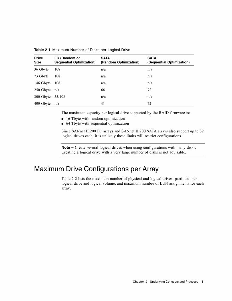
The maximum capacity per logical drive supported by the RAID firmware is:■ 16 Tbyte with random optimization■ 64 Tbyte with sequential optimization
Since SANnet II 200 FC arrays and SANnet II 200 SATA arrays also support up to 32 logical drives each, it is unlikely these limits will restrict configurations.
Note – Create several logical drives when using configurations with many disks. Creating a logical drive with a very large number of disks is not advisable.
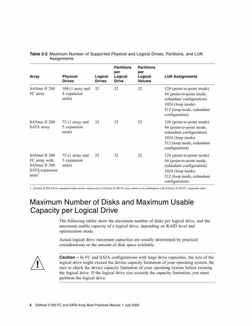
Maximum Drive Configurations per ArrayTable 2-2 lists the maximum number of physical and logical drives, partitions per logical drive and logical volume, and maximum number of LUN assignments for each array.
Table 2-1 Maximum Number of Disks per Logical Drive
Drive Size
FC (Random or Sequential Optimization)
SATA(Random Optimization)
SATA(Sequential Optimization)
36 Gbyte 108 n/a n/a
73 Gbyte 108 n/a n/a
146 Gbyte 108 n/a n/a
250 Gbyte n/a 66 72
300 Gbyte 55/108 n/a n/a
400 Gbyte n/a 41 72
Chapter 2 Underlying Concepts and Practices 5
Maximum Number of Disks and Maximum Usable Capacity per Logical Drive
The following tables show the maximum number of disks per logical drive, and the maximum usable capacity of a logical drive, depending on RAID level and optimization mode.
Actual logical drive maximum capacities are usually determined by practical considerations or the amount of disk space available.
Caution – In FC and SATA configurations with large drive capacities, the size of the logical drive might exceed the device capacity limitation of your operating system. Be sure to check the device capacity limitation of your operating system before creating the logical drive. If the logical drive size exceeds the capacity limitation, you must partition the logical drive.
Table 2-2 Maximum Number of Supported Physical and Logical Drives, Partitions, and LUN Assignments
Array Physical Drives
Logical Drives
Partitions per Logical Drive
Partitions per Logical Volume
LUN Assignments
SANnet II 200 FC array
108 (1 array and 8 expansion units)
32 32 32 128 (point-to-point mode)64 (point-to-point mode, redundant configuration)1024 (loop mode)512 (loop mode, redundant configuration)
SANnet II 200 SATA array
72 (1 array and 5 expansion units)
32 32 32 128 (point-to-point mode)64 (point-to-point mode, redundant configuration)1024 (loop mode)512 (loop mode, redundant configuration)
SANnet II 200 FC array with SANnet II 200 SATA expansion units1
1 SANnet II 200 SATA expansion units can be connected to a SANnet II 200 FC array alone or in combination with SANnet II 200 FC expansion units.
72 (1 array and 5 expansion units)
32 32 32 128 (point-to-point mode)64 (point-to-point mode, redundant configuration)1024 (loop mode)512 (loop mode, redundant configuration)
6 SANnet II 200 FC and SATA Array Best Practices Manual • July 2005
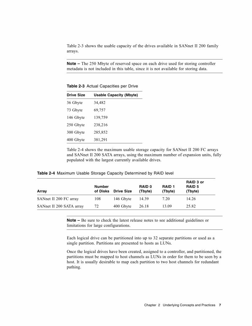
Table 2-3 shows the usable capacity of the drives available in SANnet II 200 family arrays.
Note – The 250 Mbyte of reserved space on each drive used for storing controller metadata is not included in this table, since it is not available for storing data.
Table 2-4 shows the maximum usable storage capacity for SANnet II 200 FC arrays and SANnet II 200 SATA arrays, using the maximum number of expansion units, fully populated with the largest currently available drives.
Note – Be sure to check the latest release notes to see additional guidelines or limitations for large configurations.
Each logical drive can be partitioned into up to 32 separate partitions or used as a single partition. Partitions are presented to hosts as LUNs.
Once the logical drives have been created, assigned to a controller, and partitioned, the partitions must be mapped to host channels as LUNs in order for them to be seen by a host. It is usually desirable to map each partition to two host channels for redundant pathing.
Table 2-3 Actual Capacities per Drive
Drive Size Usable Capacity (Mbyte)
36 Gbyte 34,482
73 Gbyte 69,757
146 Gbyte 139,759
250 Gbyte 238,216
300 Gbyte 285,852
400 Gbyte 381,291
Table 2-4 Maximum Usable Storage Capacity Determined by RAID level
ArrayNumber of Disks Drive Size
RAID 0 (Tbyte)
RAID 1 (Tbyte)
RAID 3 or RAID 5 (Tbyte)
SANnet II 200 FC array 108 146 Gbyte 14.39 7.20 14.26
SANnet II 200 SATA array 72 400 Gbyte 26.18 13.09 25.82
Chapter 2 Underlying Concepts and Practices 7
A partition can only be mapped to a host channel where its controller has an assigned ID. For example, if LD 0 is assigned to the primary controller, all partitions on LD 0 will need to be mapped to a host channel ID on the primary controller (PID). Any logical drives assigned to the secondary controller will need to have all partitions mapped to a host channel ID on the secondary controller (SID).
When attaching FC cables for LUNs configured with redundant paths, make sure one cable is connected to a channel on the upper controller and the other cable is connected to a different channel on the lower controller. Then, if multipathing software is configured on the host, a controller can be hot-swapped in the event of failure without losing access to the LUN.
For example, suppose partition 0 of LD 0 is mapped to Channel 0 PID 42 and Channel 5 PID 47. To ensure that there is no single point of failure (SPOF), connect a cable from the host HBA or a switch port to the upper board port FC 0, and connect a second cable from the lower board port FC 5 to a different host HBA or switch.
Cache OptimizationSANnet II 200 family arrays provide settings for both sequential I/O and random I/O. Sequential I/O is the default setting.
The RAID array’s cache optimization mode determines the cache block size used by the controller for all logical drives:■ For sequential optimization, the cache block size is 128 Kbyte.■ For random optimization, the cache block size is 32 Kbyte.
An appropriate cache block size improves performance when a particular application uses either large or small stripe sizes:■ Video playback, multimedia post-production audio and video editing, and similar
applications read and write large files in sequential order.■ Transaction-based and database update applications read and write small files in
random order.
Since the cache block size works in conjunction with the default stripe size set by the cache optimization mode for each logical drive you create, these default stripe sizes are consistent with the cache block size setting. You can, however, specify a different stripe size for any logical drive at the time you create it.
Once logical drives are created, you cannot use the RAID firmware’s “Optimization for Random I/O” or “Optimization for Sequential I/O” menu option to change the optimization mode without deleting all logical drives. You can, however, use SANscape or the SANscape CLI set cache-parameters command to change the optimization mode while logical drives exist. Refer to the “Upgrading the Configuration” chapter of the SANscape User’s Guide and the SANscape CLI User’s Guide for more information.
8 SANnet II 200 FC and SATA Array Best Practices Manual • July 2005
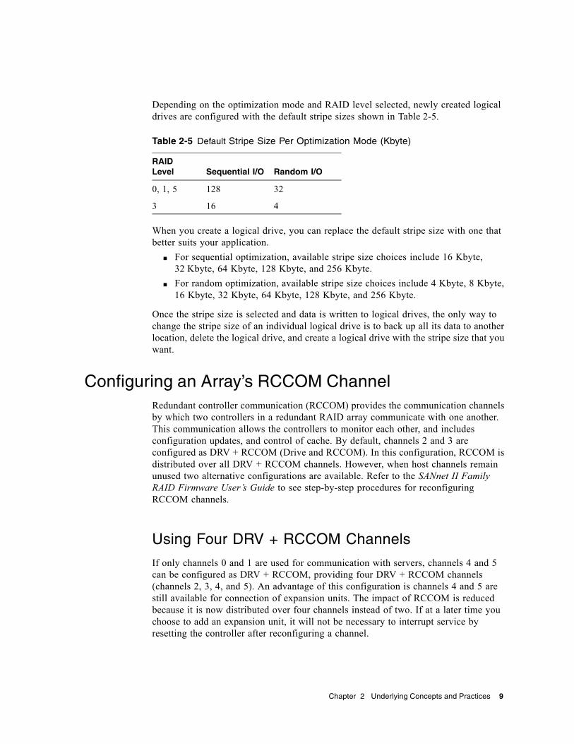
Depending on the optimization mode and RAID level selected, newly created logical drives are configured with the default stripe sizes shown in Table 2-5.
When you create a logical drive, you can replace the default stripe size with one that better suits your application.
■ For sequential optimization, available stripe size choices include 16 Kbyte, 32 Kbyte, 64 Kbyte, 128 Kbyte, and 256 Kbyte.
■ For random optimization, available stripe size choices include 4 Kbyte, 8 Kbyte, 16 Kbyte, 32 Kbyte, 64 Kbyte, 128 Kbyte, and 256 Kbyte.
Once the stripe size is selected and data is written to logical drives, the only way to change the stripe size of an individual logical drive is to back up all its data to another location, delete the logical drive, and create a logical drive with the stripe size that you want.
Configuring an Array’s RCCOM ChannelRedundant controller communication (RCCOM) provides the communication channels by which two controllers in a redundant RAID array communicate with one another. This communication allows the controllers to monitor each other, and includes configuration updates, and control of cache. By default, channels 2 and 3 are configured as DRV + RCCOM (Drive and RCCOM). In this configuration, RCCOM is distributed over all DRV + RCCOM channels. However, when host channels remain unused two alternative configurations are available. Refer to the SANnet II Family RAID Firmware User’s Guide to see step-by-step procedures for reconfiguring RCCOM channels.
Using Four DRV + RCCOM Channels
If only channels 0 and 1 are used for communication with servers, channels 4 and 5 can be configured as DRV + RCCOM, providing four DRV + RCCOM channels (channels 2, 3, 4, and 5). An advantage of this configuration is channels 4 and 5 are still available for connection of expansion units. The impact of RCCOM is reduced because it is now distributed over four channels instead of two. If at a later time you choose to add an expansion unit, it will not be necessary to interrupt service by resetting the controller after reconfiguring a channel.
Table 2-5 Default Stripe Size Per Optimization Mode (Kbyte)
RAID Level Sequential I/O Random I/O
0, 1, 5 128 32
3 16 4
Chapter 2 Underlying Concepts and Practices 9
Using Channels 4 and 5 as RCCOM Channels
When only channels 0 and 1 are used for communication with servers, another option is to assign channels 4 and 5 as dedicated RCCOM channels. This reduces the impact of RCCOM on the drive channels by removing RCCOM from drive channels 2 and 3. In this configuration, however, channels 4 and 5 cannot be used to communicate with hosts or to attach expansion modules.
Array Management ToolsSANnet II 200 family arrays use the same management interfaces and techniques. They can be configured and monitored through any of the following methods: ■ Using the out-of-band serial port connection (RAID only), a Solaris tip session or
terminal emulation program for other supported operating systems can be used to access an array’s internal firmware application. All procedures can be performed by using the firmware’s terminal interface via the COM port.
■ Using the out-of-band Ethernet port connection, a telnet session can be used to access the firmware application. All procedures except the initial assignment of an IP address can be done through an Ethernet port connection. Refer to the SANnet II 200 FC, SATA, and SATA SE Array Installation, Operations, and Service Manual for more information.
■ Using the out-of-band Ethernet port connection or in-band FC connection, SANscape or the SANscape CLI can configure and manage an array from a host system. SANscape provides a graphical user interface (GUI) that displays information about multiple aspects of the system at a glance. The main advantages of the CLI are that commands can be scripted and information can be passed to other programs.
Note – To set up and use the SANscape software package, refer to the SANscape User’s Guide. The CLI is installed as part of the sccli package. Information about CLI functionality can be found in the SANscape CLI User’s Guide, and in the sccli man page once the package is installed.
SATA drives respond more slowly than FC drives when being managed by either SANscape or the CLI. From a performance standpoint, it is preferable to use these applications out-of-band to monitor and manage a SANnet II 200 SATA array or a SANnet II 200 FC array with attached SANnet II 200 SATA expansion units. However, security considerations may take precedence over performance considerations.
If you assign an IP address to an array in order to manage it out-of-band, for security reasons consider keeping the IP address on a private network rather than a publicly routable network. Using the controller firmware to set a password for the controller limits unauthorized access to the array. Changing the firmware’s Network Protocol Support settings can provide further security by disabling the ability to remotely
10 SANnet II 200 FC and SATA Array Best Practices Manual • July 2005
connect to the array using individual protocols such as HTTP, HTTPS, telnet, FTP, and SSH. Refer to the “Communication Parameters” section of the SANnet II 200 Family RAID Firmware 4.1x User’s Guide for more information.
Note – Do not use both in-band and out-of-band connections at the same time to manage the array. Otherwise conflicts between multiple operations might occur.
Saving and Restoring Configuration InformationAn important feature of these management tools is the ability to save and restore configuration information in a number of ways. Using the array’s firmware application, the configuration information (NVRAM) can be saved to disk. This provides a backup of the controller-dependent configuration information such as channel settings, host IDs, FC protocol, and cache configuration. It does not save LUN mapping information. The NVRAM configuration file can restore all configuration settings but does not rebuild logical drives.
SANscape and the CLI can be used to save (upload) and restore (load or download) all configuration data, including LUN mapping information. These applications can also be used to rebuild all logical drives and therefore can be used to completely duplicate an array’s configuration to another array.
Chapter 2 Underlying Concepts and Practices 11

12 SANnet II 200 FC and SATA Array Best Practices Manual • July 2005
CHAPTER 3
Planning Your Storage Architecture
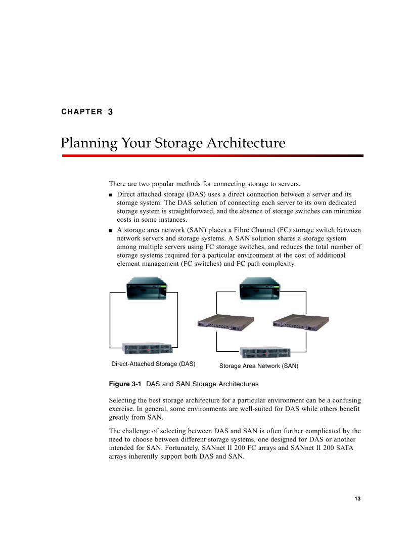
There are two popular methods for connecting storage to servers. ■ Direct attached storage (DAS) uses a direct connection between a server and its
storage system. The DAS solution of connecting each server to its own dedicated storage system is straightforward, and the absence of storage switches can minimize costs in some instances.
■ A storage area network (SAN) places a Fibre Channel (FC) storage switch between network servers and storage systems. A SAN solution shares a storage system among multiple servers using FC storage switches, and reduces the total number of storage systems required for a particular environment at the cost of additional element management (FC switches) and FC path complexity.
Figure 3-1 DAS and SAN Storage Architectures
Selecting the best storage architecture for a particular environment can be a confusing exercise. In general, some environments are well-suited for DAS while others benefit greatly from SAN.
The challenge of selecting between DAS and SAN is often further complicated by the need to choose between different storage systems, one designed for DAS or another intended for SAN. Fortunately, SANnet II 200 FC arrays and SANnet II 200 SATA arrays inherently support both DAS and SAN.
Direct-Attached Storage (DAS) Storage Area Network (SAN)
13
Direct-Attached StorageOne powerful feature of SANnet II 200 FC arrays and SANnet II 200 SATA arrays is their ability to support multiple direct-attached servers without requiring storage switches. They accomplish this by using intelligent internal FC networks. Servers can be directly connected using built-in external FC ports, if available, or add-in FC host adapter cards.■ SANnet II 200 FC arrays automatically configure ports to match the transfer speed
and communication method of each connection.
Note – Some older 1-Gbyte FC HBAs do not correctly support current auto-negotiation. In such configurations, set the transfer speed to 1-Gbyte rather than Auto. Refer to the release notes to see the HBAs supported for your host and any limitations. Refer to the SANnet II Family RAID Firmware User’s Guide for information about how to set transfer speed.
■ For SANnet II 200 SATA arrays, channels 0 and 1 automatically configure their ports to match the transfer speed and communication method of each connection. Channels 4 and 5 only support a 2-Gbyte transfer rate.
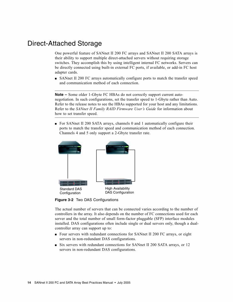
Figure 3-2 Two DAS Configurations
The actual number of servers that can be connected varies according to the number of controllers in the array. It also depends on the number of FC connections used for each server and the total number of small form-factor pluggable (SFP) interface modules installed. DAS configurations often include single or dual servers only, though a dual-controller array can support up to:■ Four servers with redundant connections for SANnet II 200 FC arrays, or eight
servers in non-redundant DAS configurations.■ Six servers with redundant connections for SANnet II 200 SATA arrays, or 12
servers in non-redundant DAS configurations.
High Availability DAS Configuration
Standard DASConfiguration
14 SANnet II 200 FC and SATA Array Best Practices Manual • July 2005
Note – Do not use a SANnet II 200 SATA array to store single instances of data. It is more suitable for use in configurations where the array has a backup or archival role.
Additional SFP modules are required to support more than two servers with redundant connections or four servers in non-redundant configurations. For information about obtaining and relocating SFP modules, refer to the SANnet II 200 FC, SATA, and SATA SE Array Installation, Operations, and Service Manual for the SANnet II 200 FC Array and SANnet II 200 SATA Array.
Note – Except in some clustering configurations, in a DAS loop configuration when you connect two hosts to channel 0 (both FC 0 ports of either controller), or channel 1 (both FC 1 ports of either controller) on a SANnet II 200 SATA array, you must use host filtering if you want to control host access to storage. Refer to the user documentation for your clustering software to determine whether the clustering software can manage host access in this configuration.
Storage Area NetworkingCombining storage switches with a SANnet II 200 series array configuration creates a SAN, increasing the number of servers that can be connected. Essentially, the maximum number of servers that can be connected to the SAN becomes equal to the number of available storage switch ports. Storage switches generally include the ability to manage and monitor the FC networks they create, which can reduce storage management workloads in multiple server environments.
SANnet II 200 FC arrays and SANnet II 200 SATA arrays are designed to be deployed in SANs based on switched FC fabrics. In a SAN scenario, the server HBAs are connected to one side of the fabric and storage is connected to the other. A SAN fabric automatically routes FC packets between ports on one or many FC switches.
SAN deployment enables SANnet II 200 FC arrays and SANnet II 200 SATA arrays to be used by a larger number of hosts. This storage strategy tends to utilize storage resources more effectively and is commonly referred to as storage consolidation.
The number of hosts that can effectively share one SANnet II 200 FC array or SATA array depends on several factors such as the type of host application, bandwidth requirements, and the need for concurrent input/output operations per second (IOPS). Since most applications have moderate performance needs, it is quite feasible to have several hosts sharing the same SANnet II 200 FC or SATA array controller, with the following network characteristics:■ Applications suitable for the SANnet II 200 SATA array might feature higher
bandwidth and lower IOPS than those better suited to the SANnet II 200 FC array. Sharing a SANnet II 200 SATA array effectively among several servers depends on the division of performance among the applications installed on each server actively accessing the SANnet II 200 SATA array.
Chapter 3 Planning Your Storage Architecture 15

■ The SANnet II 200 FC array is better suited for larger configurations with broader application requirements and higher IOPs.
A SAN can also support multiple SANnet II 200 FC arrays and SANnet II 200 SATA arrays. Increasing the number of arrays makes more performance and capacity available within a storage network for sharing among the servers connected to the SAN. A SAN also provides great flexibility in how storage capacity can be allocated among servers and eliminates cabling changes when reallocation of storage becomes necessary.
When a SANnet II 200 FC array or SATA array is deployed in a SAN, both point-to-point (full fabric) and arbitrated loop (public loop) modes are supported. Point-to-point mode enables superior full-duplex performance but limits the total number of addressable LUNs to 128, or to 64 when redundant pathing is used.
Scaling CapacitySANnet II 200 FC arrays and SANnet II 200 SATA arrays are available in a number of configurations to address a broad range of storage capacities. ■ The SANnet II 200 FC array is available with 15,000 RPM FC disks to address
high-performance requirements.■ The SANnet II 200 SATA array is available in larger capacities to better address the
needs of the bulk storage market. The additional storage capacity of the SANnet II 200 SATA array provides more storage for each server attached. Larger capacity disks do not effectively support large groups of servers or users, so spreading the extra capacity among a larger number of servers results in poor performance and, in extreme cases, possible loss of data.
Base systems include single or redundant controllers and a choice of five or twelve disks. Additional storage capacity can be dynamically created, starting with a system with five disks and then adding one or more disks. Expansion units can be dynamically added to base systems when more storage capacity is required than a single array can provide.
Note – A SANnet II 200 FC array can be connected to as many as eight SANnet II 200 FC expansion units. Alternatively, SANnet II 200 FC arrays can be connected to as many as five SANnet II 200 SATA expansion units or combined FC and SATA expansion units. SANnet II 200 SATA arrays, however, can only be connected to SANnet II 200 SATA expansion units. See “Combining SANnet II 200 FC Arrays and SANnet II 200 SATA Expansion Units” on page 53 for more information.
SANnet II 200 FC arrays and SANnet II 200 SATA arrays remain single storage systems as expansion units are added, even though there are multiple interconnected physical units. Expansion units simply add bays to base units to increase the total number of disks that can be supported.
16 SANnet II 200 FC and SATA Array Best Practices Manual • July 2005
See “Maximum Number of Disks and Maximum Usable Capacity per Logical Drive” on page 6 for maximum capacities per RAID configuration.
First Steps in Designing a SolutionThere are two simple yet effective approaches for designing a SANnet II 200 FC array or SATA array solution into your environment. Both methods allow for the rapid estimation of an appropriate DAS or SAN solution. Regardless of which method is used, the storage needs of each application and server involved must be identified to establish the total amount of storage capacity required.
Designing a Storage Solution for an Existing Environment
The first method works well for existing environments. Start by identifying the number of servers that can immediately benefit from the storage a SANnet II 200 FC array or SATA array provides. ■ A SANnet II 200 FC array can support five or more servers. If there are four or
fewer servers, a DAS solution is sufficient.■ A SANnet II 200 SATA array can support seven or more servers. If there are six or
fewer servers, a DAS solution is sufficient. If you connect two servers to channel 0 or to channel 1, use host filtering if you want to control host access to logical drives.
With either the SANnet II 200 FC array or SATA array, a SAN solution can be a powerful option, even when the array is connected to a number of servers that can otherwise be supported in a DAS solution. Combining both the SANnet II 200 FC array and SANnet II 200 SATA array on the same SAN allows for a tiered storage strategy. Determine how much storage is currently accessible to these servers and plan for that total capacity as the minimum amount of SANnet II 200 family disk capacity needed.
Designing a New Storage Solution
Another technique involves matching a particular environment to one of the best practices solutions described in this document. This approach works particularly well with new deployments, but it can be used for existing environments as well. Take note of special features, such as the number of connections between servers and storage. While these solutions do not match every environment exactly, use the closest one as a design blueprint that can be customized to suite your particular environment. For environments with different server configurations, choose the solution that best matches the servers whose applications are mission-critical or most important.
Chapter 3 Planning Your Storage Architecture 17
General Configuration Considerations
The entry-level configuration for an FC or SATA array uses only one RAID controller. If this configuration is used, two single-controller arrays should use host-based mirroring to ensure high reliability, availability, and serviceability.
Note – Refer to product documentation for VERITAS Volume Manager or an equivalent host mirroring application to set up the optimum configuration with single-controller arrays.
Use dual-controller arrays to avoid a single point of failure. A dual-controller FC array features a default active-to-active controller configuration. This configuration improves application availability because, in the unlikely event of a controller failure, the array automatically fails over to a second controller, resulting in no interruption of data flow. Single controller arrays are provided for small configurations requiring fast, scratch disk, as in EDA environments.
SANnet II 200 FC and SATA arrays are extremely flexible, but when designing storage solutions remember to keep them as simple as possible. Keep the following suggestions in mind when designing the configuration of a FC storage system:■ To ensure power redundancy, connect the two power modules to two separate
circuits, such as one commercial circuit and one UPS.■ In a single-controller configuration, disable the Write-Back Cache feature to avoid
the possibility of data corruption in the event of a controller failure. This will have a negative effect on performance. To avoid either issue, use dual controllers. You can also use the RAID firmware to create event triggers that temporarily disable the Write-Back Cache feature in the event of hardware failures or out-of-spec environmental conditions.
■ Using two single-controllers in a clustering environment with host-based mirroring provides some of the advantages of using a dual controller. However, you still need to disable the Write-Back Cache in case one of the single controllers fails and you want to avoid data corruption. For this reason, a dual-controller configuration is preferable.
■ Prior to creating logical drives and mapping them to host channels, set the appropriate cache optimization, FC protocol, and controller channel IDs. Reset the controller after these configuration parameters have been set.
■ For best performance and RAS, create logical drives across expansion units.■ To avoid disruptions to other hosts sharing the same array, do not share a logical
drive among multiple hosts.■ Use either local or global spare drives when creating logical drives. Any free drive
can be designated as a spare and more than one drive can be used as a spare.■ Use dual pathing for each LUN and use SANpath software to provide load
balancing across controller ports for increased performance.■ The maximum number of LUNs when using point-to-point protocol is 128 for
single-path configurations and 64 for dual-path configurations.
18 SANnet II 200 FC and SATA Array Best Practices Manual • July 2005
■ Power-up the equipment in the following order:a. Expansion unitsb. RAID arrayc. Host computers
■ Connect the Ethernet management ports to a private Ethernet network.■ For security reasons, use the RAID firmware to assign a password to the RAID
controller.■ Changing the firmware’s Network Protocol Support settings can provide further
security by disabling the ability to remotely connect to the array using individual protocols such as HTTP, HTTPS, telnet, FTP, and SSH.
■ After completing the configuration of a SANnet II 200 FC array or SATA array, the configuration should be saved using the firmware Save nvram to disks menu option or the SANscape save configuration option.
Chapter 3 Planning Your Storage Architecture 19

20 SANnet II 200 FC and SATA Array Best Practices Manual • July 2005
CHAPTER 4
DAS Configurations
This chapter presents several DAS configurations you can use.
Single-Controller DAS Configurations
Note – Using single connections between Fibre Channel (FC) arrays and servers creates single points of failure (SPOF) that can cause interruptions in the event a connection becomes unreliable or fails. This is not a recommended configuration unless host-based mirroring is utilized to protect against single points of failure. Similarly, using only a single controller creates a single point of failure, unless single controllers are used in pairs and mirrored. Using a dual-controller configuration, as shown in “Dual-Controller Multipath DAS Configurations” on page 25, is preferable to using a single controller or a pair of single controllers.
21
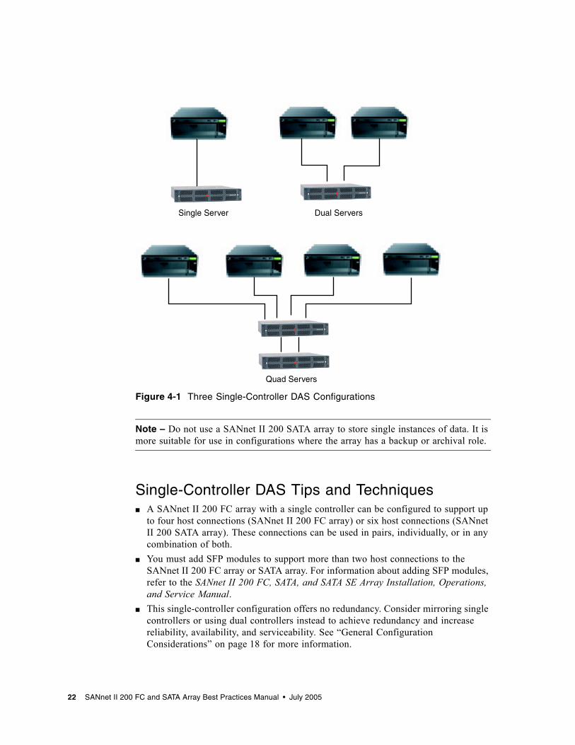
Figure 4-1 Three Single-Controller DAS Configurations
Note – Do not use a SANnet II 200 SATA array to store single instances of data. It is more suitable for use in configurations where the array has a backup or archival role.
Single-Controller DAS Tips and Techniques■ A SANnet II 200 FC array with a single controller can be configured to support up
to four host connections (SANnet II 200 FC array) or six host connections (SANnet II 200 SATA array). These connections can be used in pairs, individually, or in any combination of both.
■ You must add SFP modules to support more than two host connections to the SANnet II 200 FC array or SATA array. For information about adding SFP modules, refer to the SANnet II 200 FC, SATA, and SATA SE Array Installation, Operations, and Service Manual.
■ This single-controller configuration offers no redundancy. Consider mirroring single controllers or using dual controllers instead to achieve redundancy and increase reliability, availability, and serviceability. See “General Configuration Considerations” on page 18 for more information.
Dual ServersSingle Server
Quad Servers
22 SANnet II 200 FC and SATA Array Best Practices Manual • July 2005
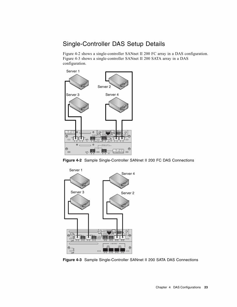
Single-Controller DAS Setup Details
Figure 4-2 shows a single-controller SANnet II 200 FC array in a DAS configuration. Figure 4-3 shows a single-controller SANnet II 200 SATA array in a DAS configuration.
Figure 4-2 Sample Single-Controller SANnet II 200 FC DAS Connections
Figure 4-3 Sample Single-Controller SANnet II 200 SATA DAS Connections
Server 1
Server 2
Server 4Server 3
H/D/RCC
Server 3 Server 2
Server 1Server 4
Chapter 4 DAS Configurations 23
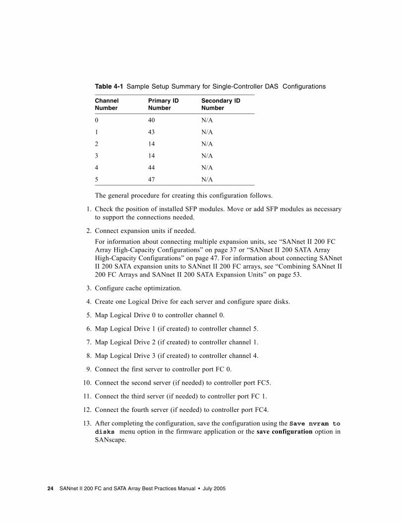
The general procedure for creating this configuration follows.
1. Check the position of installed SFP modules. Move or add SFP modules as necessary to support the connections needed.
2. Connect expansion units if needed.For information about connecting multiple expansion units, see “SANnet II 200 FC Array High-Capacity Configurations” on page 37 or “SANnet II 200 SATA Array High-Capacity Configurations” on page 47. For information about connecting SANnet II 200 SATA expansion units to SANnet II 200 FC arrays, see “Combining SANnet II 200 FC Arrays and SANnet II 200 SATA Expansion Units” on page 53.
3. Configure cache optimization.
4. Create one Logical Drive for each server and configure spare disks.
5. Map Logical Drive 0 to controller channel 0.
6. Map Logical Drive 1 (if created) to controller channel 5.
7. Map Logical Drive 2 (if created) to controller channel 1.
8. Map Logical Drive 3 (if created) to controller channel 4.
9. Connect the first server to controller port FC 0.
10. Connect the second server (if needed) to controller port FC5.
11. Connect the third server (if needed) to controller port FC 1.
12. Connect the fourth server (if needed) to controller port FC4.
13. After completing the configuration, save the configuration using the Save nvram to disks menu option in the firmware application or the save configuration option in SANscape.
Table 4-1 Sample Setup Summary for Single-Controller DAS Configurations
Channel Number
Primary ID Number
Secondary ID Number
0 40 N/A
1 43 N/A
2 14 N/A
3 14 N/A
4 44 N/A
5 47 N/A
24 SANnet II 200 FC and SATA Array Best Practices Manual • July 2005
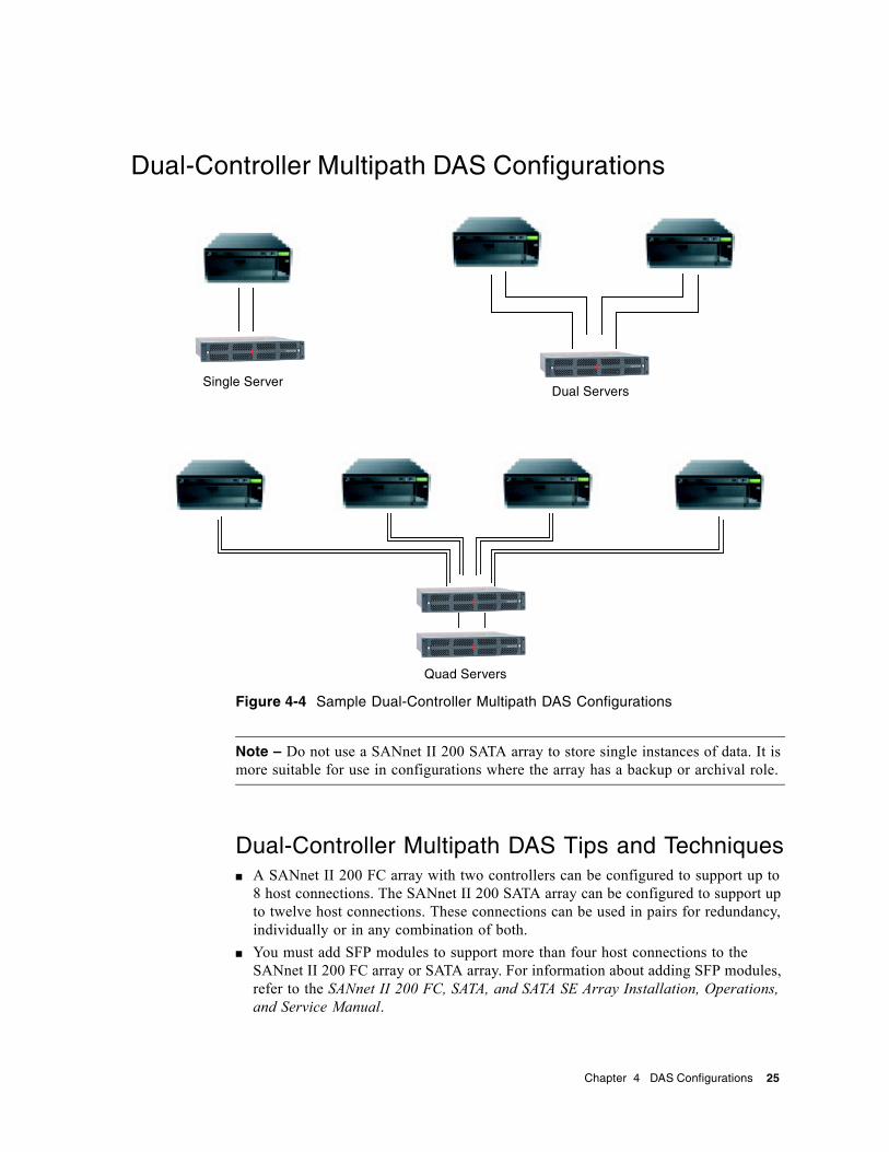
Dual-Controller Multipath DAS Configurations
Figure 4-4 Sample Dual-Controller Multipath DAS Configurations
Note – Do not use a SANnet II 200 SATA array to store single instances of data. It is more suitable for use in configurations where the array has a backup or archival role.
Dual-Controller Multipath DAS Tips and Techniques■ A SANnet II 200 FC array with two controllers can be configured to support up to
8 host connections. The SANnet II 200 SATA array can be configured to support up to twelve host connections. These connections can be used in pairs for redundancy, individually or in any combination of both.
■ You must add SFP modules to support more than four host connections to the SANnet II 200 FC array or SATA array. For information about adding SFP modules, refer to the SANnet II 200 FC, SATA, and SATA SE Array Installation, Operations, and Service Manual.
Single ServerDual Servers
Quad Servers
Chapter 4 DAS Configurations 25
■ Using two single-port 2-Gbit FC host adapters in a high-availability configuration makes optimum use of a FC array’s redundancy. Mapping logical drive partitions to two paths while using multipathing software provides the best redundancy.
■ For complete redundancy and high availability, use host-based multipathing software such as SANpath. To configure multipathing:■ Establish two connections between a server and a SANnet II 200 FC array.■ Install and enable the software on the server.■ Map the logical drive to both of the controller channels to which the server is
connected.
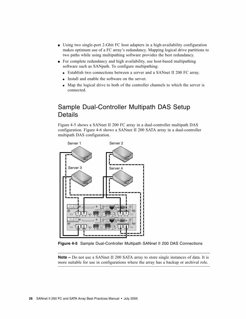
Sample Dual-Controller Multipath DAS Setup Details
Figure 4-5 shows a SANnet II 200 FC array in a dual-controller multipath DAS configuration. Figure 4-6 shows a SANnet II 200 SATA array in a dual-controller multipath DAS configuration.
Figure 4-5 Sample Dual-Controller Multipath SANnet II 200 DAS Connections
Note – Do not use a SANnet II 200 SATA array to store single instances of data. It is more suitable for use in configurations where the array has a backup or archival role.
Server 1
Server 3
Server 2
Server 4
26 SANnet II 200 FC and SATA Array Best Practices Manual • July 2005
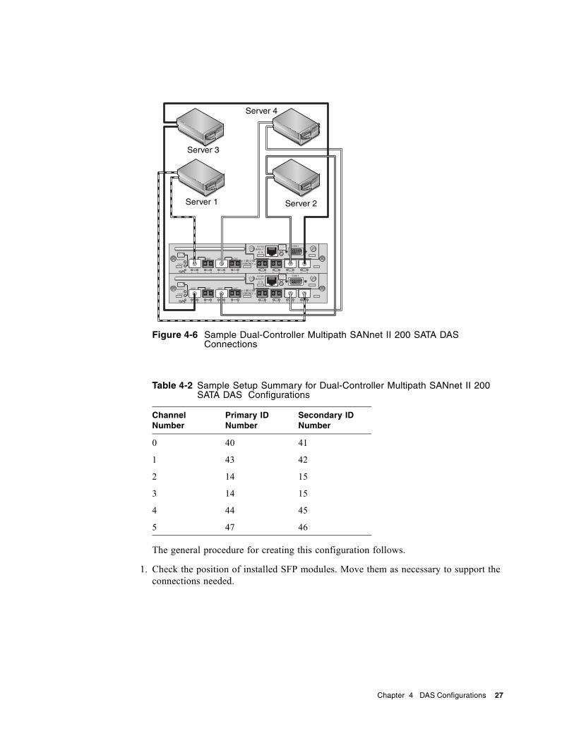
Figure 4-6 Sample Dual-Controller Multipath SANnet II 200 SATA DAS Connections
The general procedure for creating this configuration follows.
1. Check the position of installed SFP modules. Move them as necessary to support the connections needed.
Table 4-2 Sample Setup Summary for Dual-Controller Multipath SANnet II 200 SATA DAS Configurations
Channel Number
Primary ID Number
Secondary ID Number
0 40 41
1 43 42
2 14 15
3 14 15
4 44 45
5 47 46
H/D/RCC
H/D/RCC
Server 1
Server 4
Server 3
Server 2
Chapter 4 DAS Configurations 27
2. Connect expansion units if needed.For information about connecting multiple expansion units, see “SANnet II 200 FC Array High-Capacity Configurations” on page 37 or “SANnet II 200 SATA Array High-Capacity Configurations” on page 47. For information about connecting SANnet II 200 SATA expansion units to SANnet II 200 FC arrays, see “Combining SANnet II 200 FC Arrays and SANnet II 200 SATA Expansion Units” on page 53.
3. Configure cache optimization.
4. Ensure that the fibre connection is set to loop mode.
5. Configure target IDs.
6. Create one Logical Drive for each server and configure spare disks.
7. Map Logical Drive 0 to channels 0 and 4 of the primary controller.
8. Map Logical Drive 1 (if created) to channels 1 and 5 of the secondary controller.
9. Map Logical Drive 2 to channels 0 and 4 of the primary controller.
10. Map Logical Drive 3 (if created) to channels 1 and 5 of the secondary controller.
11. Connect the first server (Server 1) to port FC 0 of the upper controller and port FC5 of the lower controller.
12. Connect the second server (Server 2), if needed to port FC 1 of the lower controller and port FC4 of the upper controller.
13. Connect the third server (Server 3), if needed to port FC 0 of the lower controller and port FC5 of the upper controller.
14. Connect the fourth server (Server 4), if needed to port FC 1 of the upper controller and port FC4 of the lower controller.
15. Install and enable multipathing software on each connected server.
16. After completing the configuration, save the configuration using the Save nvram to disks menu option in the firmware application or the save configuration option in SANscape.
28 SANnet II 200 FC and SATA Array Best Practices Manual • July 2005

CHAPTER 5
SAN Configurations
This chapter presents several SAN configurations you can use.
Full-Duplex SAN Configurations
Figure 5-1 Typical Full-Fabric SAN Configuration
Note – Do not use a SANnet II 200 SATA array to store single instances of data. It is more suitable for use in configurations where the array has a backup or archival role.
29

Full-Duplex SAN Tips and Techniques■ In a full-duplex SAN configuration, the switches communicate with the array host
ports using a fabric point-to-point (F_port) mode. This enables transparent controller fail-over and fail-back without server-resident software. However, supporting hot-swap servicing of a failed controller requires the use of multipathing software, such as SANpath, on the connected servers.
■ Use of fabric point-to-point (F_port) connections between an array and fabric switches limits to 128 the total number of LUNs that can be presented. Fibre channel (FC) standards allow only one ID per port when operating point-to-point protocols, resulting in a maximum of four IDs, with a maximum of 32 LUNs each, supporting up to 128 LUNs.
■ When a fabric switch is connected to one port of channel 0 or channel 1 of a SANnet II 200 SATA array, no connections can be made with the other three ports of that channel. If channel 0 (port FC 0) is connected to a fabric switch, for example, the second port for channel 0 on that controller, and the FC 0 ports on a redundant controller, cannot be used. Similarly, if channel 1 (port FC 1) is connected to a fabric switch, the second FC 1 port on that controller and the FC 1 ports on a redundant controller cannot be used.
Sample Full-Duplex SAN Setup Details
Figure 5-2 shows a SANnet II 200 FC array in a full-duplex SAN configuration. Figure 5-3 shows a SANnet II 200 SATA array in a full-duplex SAN configuration.
Figure 5-2 Sample SANnet II 200 FC Full-Duplex SAN Connections
Server 1 Server 2
Switch 1 Switch 2
30 SANnet II 200 FC and SATA Array Best Practices Manual • July 2005
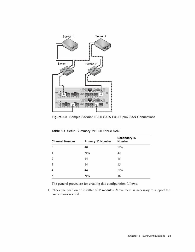
Figure 5-3 Sample SANnet II 200 SATA Full-Duplex SAN Connections
The general procedure for creating this configuration follows.
1. Check the position of installed SFP modules. Move them as necessary to support the connections needed.
Table 5-1 Setup Summary for Full Fabric SAN
Channel Number Primary ID NumberSecondary ID Number
0 40 N/A
1 N/A 42
2 14 15
3 14 15
4 44 N/A
5 N/A 46
H/D/RCC
H/D/RCC
Server 1 Server 2
Switch 1 Switch 2
Chapter 5 SAN Configurations 31
2. Connect expansion units if needed.For information about connecting multiple expansion units, see “SANnet II 200 FC Array High-Capacity Configurations” on page 37 or “SANnet II 200 SATA Array High-Capacity Configurations” on page 47. For information about connecting SANnet II 200 SATA expansion units to SANnet II 200 FC arrays, see “Combining SANnet II 200 FC Arrays and SANnet II 200 SATA Expansion Units” on page 53.
3. Configure cache optimization.
4. Ensure that the fibre connection is set to point-to-point.
5. Ensure only one target ID per channel is configured.
6. Create at least two logical drives and configure spare disks.
7. Create one or more logical drive partitions for each server.
8. Map Logical Drive 0 to channels 0 and 4 of the primary controller
9. Map Logical Drive 1 to channels 1 and 5 of the secondary controller.
10. If more than two logical drives were created, map even-numbered logical drives to channels 0 and 4 of the primary controller and odd-numbered logical drives to channels 1 and 5 of the secondary controller.
11. Connect the first switch to port FC 0 of the upper controller and port FC 1 of the lower controller.
12. Connect the second switch to port FC4 of the lower controller and port FC5 of the upper controller.
13. Connect each server to each switch.
14. Install and enable multipathing software on each connected server.
15. After completing the configuration, save the configuration using the Save nvram to disks menu option in the firmware application or the save configuration option in SANscape.
32 SANnet II 200 FC and SATA Array Best Practices Manual • July 2005
Redundant Point-to-Point SAN Configurations
Figure 5-4 Sample Redundant Point-to-Point SAN Configuration
Note – Do not use a SANnet II 200 SATA array to store single instances of data. It is more suitable for use in configurations where the array has a backup or archival role.
Redundant Point-to-Point Tips and Techniques■ In the redundant point-to-point SAN configuration, the switches communicate with
the array host ports using a fabric point-to-point (F_port) mode. This enables transparent controller fail-over and fail-back without server-resident software. However, supporting hot-swap servicing of a failed controller requires the use of multipathing software, such as SANpath, on the connected servers.
■ Use of fabric point-to-point (F_port) connections between an array and fabric switches limits to 128 the total number of LUNs that can be presented. FC standards allow only one ID per port when operating point-to-point protocols, resulting in a maximum of four IDs, with a maximum of 32 LUNs each, supporting up to 128 LUNs.
■ When a fabric switch is connected to one port of channel 0 or channel 1 of a SANnet II 200 SATA array, no connections can be made with the other three ports of that channel. If channel 0 (port FC 0) is connected to a fabric switch, for example, the second port for channel 0 on that controller, and the FC 0 ports on a redundant controller, cannot be used. Similarly, if channel 1 (port FC 1) is connected to a fabric switch, the second port for channel 1 on that controller and both FC 1 ports on a redundant controller cannot be used.
Chapter 5 SAN Configurations 33

Redundant Point-to-Point Setup Details
Figure 5-5 shows a SANnet II 200 FC array in a redundant point-to-point SAN configuration. Figure 5-6 shows a SANnet II 200 SATA array in a redundant point-to-point SAN configuration.
Figure 5-5 Sample Redundant Point-to-Point SANnet II 200 FC SAN Connections
Server 1 Server 2
Switch 1 Switch 2
34 SANnet II 200 FC and SATA Array Best Practices Manual • July 2005
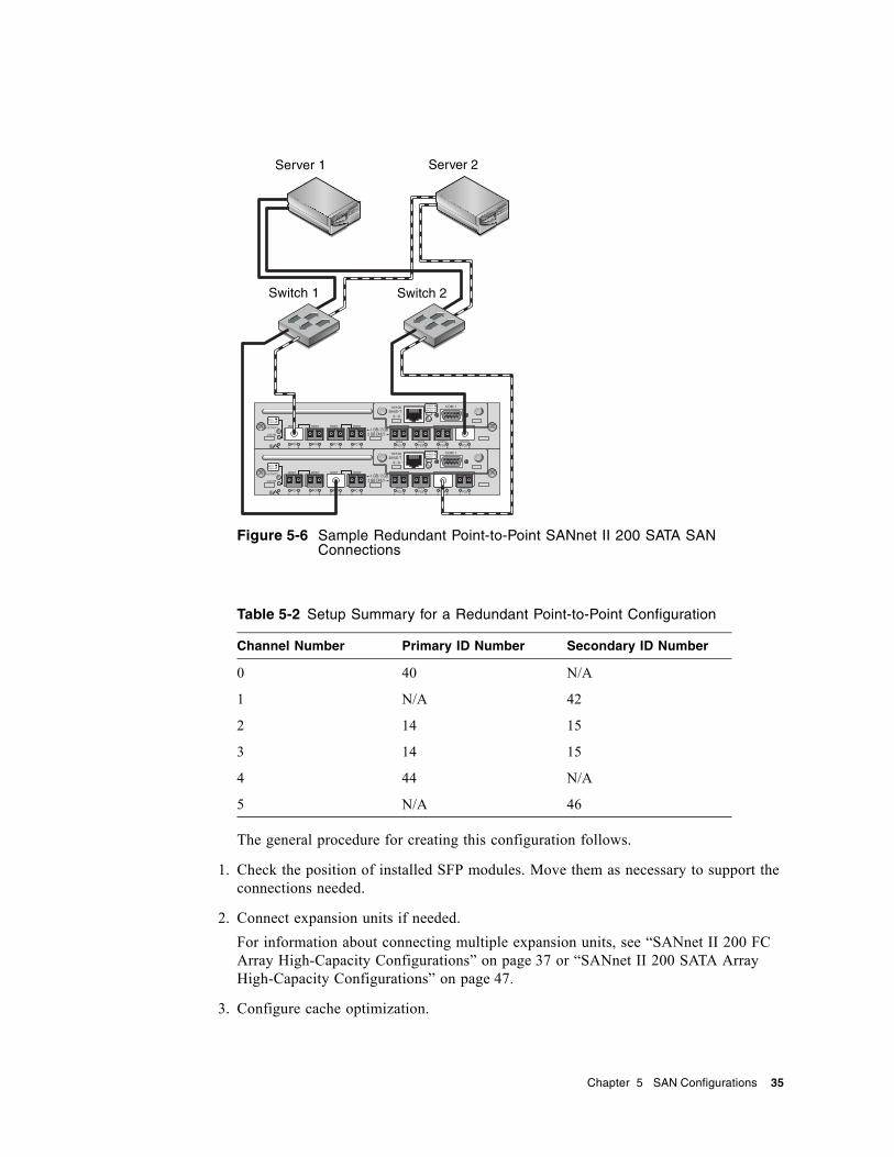
Figure 5-6 Sample Redundant Point-to-Point SANnet II 200 SATA SAN Connections
The general procedure for creating this configuration follows.
1. Check the position of installed SFP modules. Move them as necessary to support the connections needed.
2. Connect expansion units if needed.For information about connecting multiple expansion units, see “SANnet II 200 FC Array High-Capacity Configurations” on page 37 or “SANnet II 200 SATA Array High-Capacity Configurations” on page 47.
3. Configure cache optimization.
Table 5-2 Setup Summary for a Redundant Point-to-Point Configuration
Channel Number Primary ID Number Secondary ID Number
0 40 N/A
1 N/A 42
2 14 15
3 14 15
4 44 N/A
5 N/A 46
H/D/RCC
H/D/RCC
Server 1 Server 2
Switch 1 Switch 2
Chapter 5 SAN Configurations 35
4. Ensure that the fibre connection is set to point-to-point mode.
5. Configure target IDs.
6. Create at least two logical drives and configure spare disks.
7. Assign even-numbered logical drives beginning with Logical Drive 0 to the primary controller.
8. Assign odd-numbered logical drives beginning with Logical Drive 1 to the secondary controller.
9. Create one or more logical drive partitions for each server.
10. Map the LUNs from even-numbered logical drives beginning with Logical Drive 0 to channels 0 and 4 of the primary controller.
11. Map the LUNs from even-numbered logical drives beginning with Logical Drive 1 to channels 1 and 5 of the secondary controller.
Note – See “Fibre Channel Protocols” on page 3 for a description of the maximum number of devices you can map in various configurations.
12. Connect the first switch to port FC 0 of the upper controller and port FC 1 of the lower controller.
13. Connect the second switch to port FC4 of the lower controller and port FC5 of the upper controller.
14. Connect each server to each switch.
15. Install and enable multipathing software on each connected server.
16. After completing the configuration, save the configuration using Save nvram to disks menu option in the firmware application and the save configuration option in SANscape.
36 SANnet II 200 FC and SATA Array Best Practices Manual • July 2005
CHAPTER 6
Using Multiple Expansion Units in High Capacity Configurations
High-capacity configurations using multiple expansion units are appropriate for some situations, although using multiple arrays connected to the same SAN generally offers significantly better performance than a single high-capacity configuration. High-capacity configurations require considerable planning in order to connect expansion units in a way that ensures maximum reliability, availability, and serviceability (RAS), and avoids single points of failure.
This chapter presents a few limitations on high-capacity configurations you should consider, and shows you sample configurations for up to eight SANnet II 200 FC expansion units. The following chapter shows you sample configurations for up to five SANnet II 200 SATA expansion units when connected to a SANnet II 200 SATA array.
“Combining SANnet II 200 FC Arrays and SANnet II 200 SATA Expansion Units” on page 53 describes how you might connect two SANnet II 200 SATA expansion units and three SANnet II 200 FC expansion units to a SANnet II 200 FC array, along with a description of a possible use for such a configuration.
SANnet II 200 FC Array High-Capacity ConfigurationsSANnet II 200 FC arrays typically allow the connection of up to two expansion units to support a maximum of 36 disks. However, you can create larger configurations that support as many as eight expansion units and up to 108 disks if you use the guidelines in this section.
See “SANnet II 200 SATA Array High-Capacity Configurations” on page 47 for information about adding expansion units to a SANnet II 200 SATA array.
These configurations work best when you select the highest-capacity disk available without exceeding maximum limits set by the firmware. Refer to the SANnet II Family FRU Installation Guide for information about supported disk drives, cables, SFPs, and other user-replaceable items.
The use of a full-fabric SAN configuration is highly recommended for host connections, as shown in “Full-Duplex SAN Configurations” on page 29.”
37

Note – The following high-capacity configurations illustrate cabling techniques for drive ports. They must be combined with a standard configuration shown in this document, such as shown in “Redundant Point-to-Point SAN Configurations” on page 33.
Limitations■ Maximize the size of each logical drive before creating another logical drive.
Otherwise the maximum number of 32 logical drives might limit future expansion.■ Limiting the maximum number of expansion units on a SANnet II 200 FC array to
seven provides greater configuration flexibility. Doing so enables the use of up to 96 disks.
■ Many of these configurations require the use of optional extended-length cables. Other items may also be required. Refer to the SANnet II Family FRU Installation Guide for information about supported cables, SFPs, and other user-replaceable items.
Connecting One Expansion Unit
Figure 6-1 SANnet II 200 FC Array Configuration with One Expansion Unit
38 SANnet II 200 FC and SATA Array Best Practices Manual • July 2005
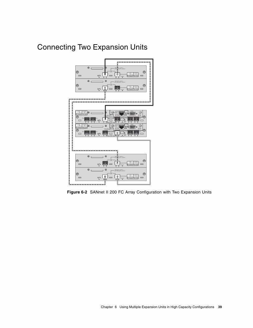
Connecting Two Expansion Units
Figure 6-2 SANnet II 200 FC Array Configuration with Two Expansion Units
Chapter 6 Using Multiple Expansion Units in High Capacity Configurations 39
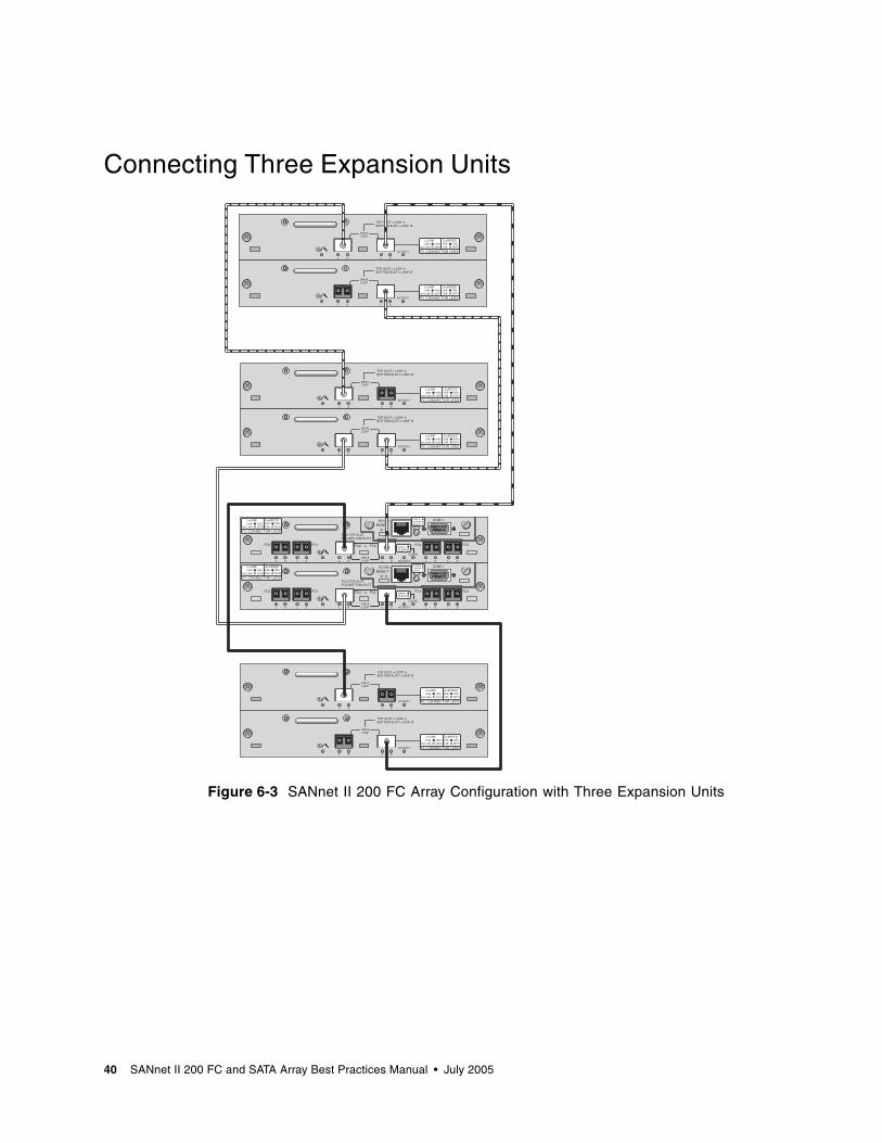
Connecting Three Expansion Units
Figure 6-3 SANnet II 200 FC Array Configuration with Three Expansion Units
40 SANnet II 200 FC and SATA Array Best Practices Manual • July 2005

Connecting Four Expansion Units
Figure 6-4 SANnet II 200 FC Array Configuration with Four Expansion Units
Connecting Five Expansion UnitsThis high-capacity configuration using five expansion units requires the configuration of RAID channels 4 and 5 as drive channels. This restricts host connections to RAID channels 0 and 1, affecting supported host configurations. Use four expansion units or fewer when possible.
Chapter 6 Using Multiple Expansion Units in High Capacity Configurations 41
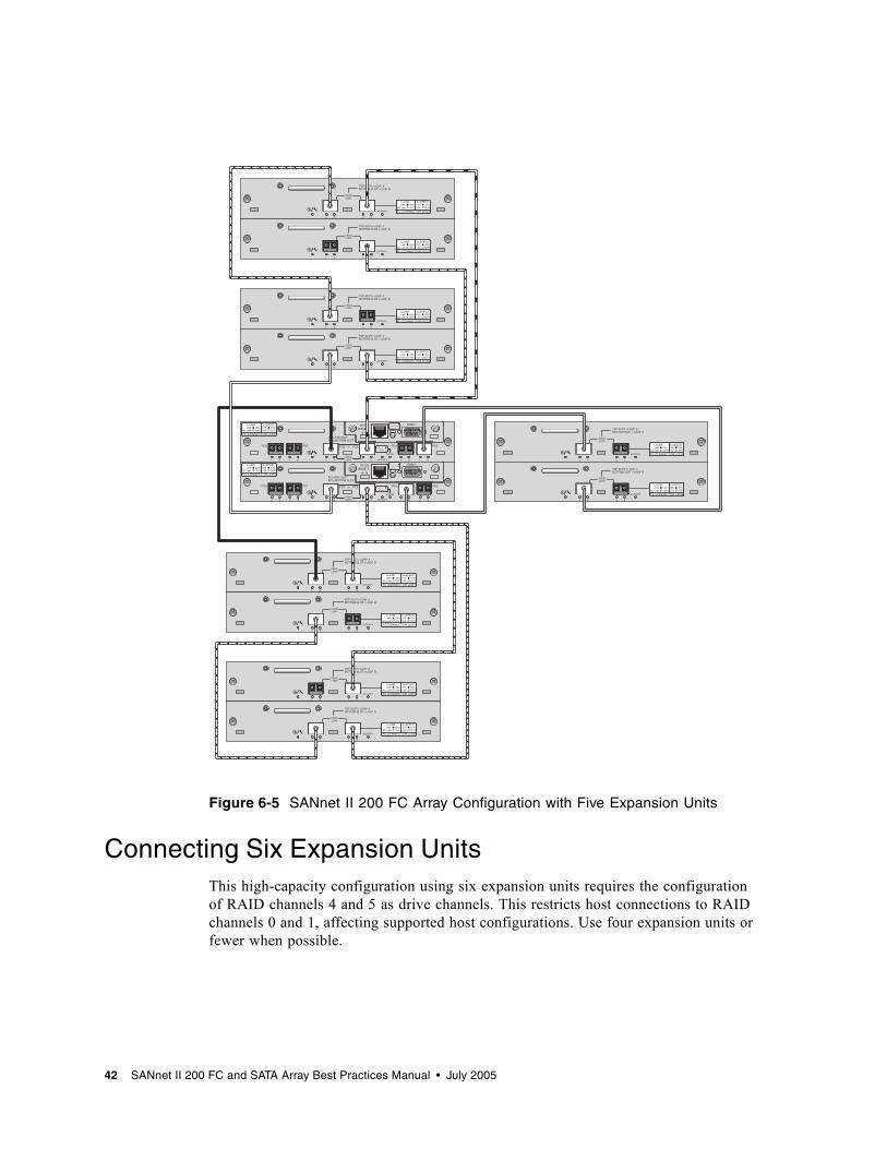
Figure 6-5 SANnet II 200 FC Array Configuration with Five Expansion Units
Connecting Six Expansion UnitsThis high-capacity configuration using six expansion units requires the configuration of RAID channels 4 and 5 as drive channels. This restricts host connections to RAID channels 0 and 1, affecting supported host configurations. Use four expansion units or fewer when possible.
42 SANnet II 200 FC and SATA Array Best Practices Manual • July 2005
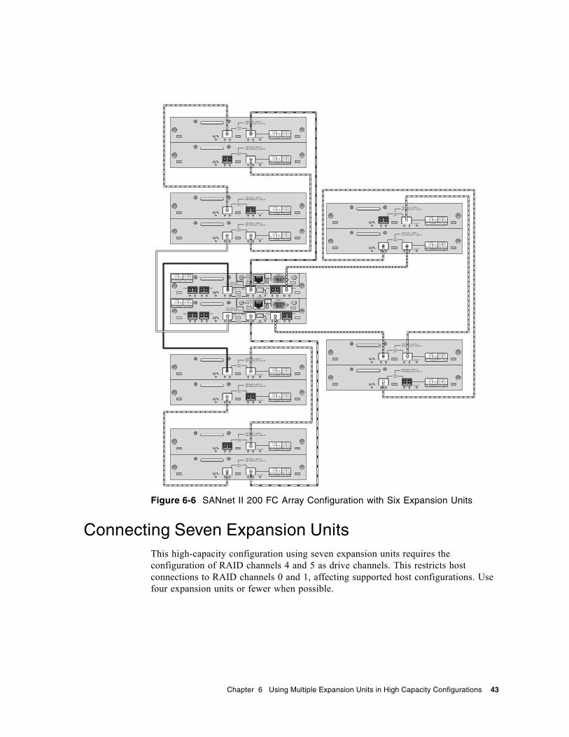
Figure 6-6 SANnet II 200 FC Array Configuration with Six Expansion Units
Connecting Seven Expansion UnitsThis high-capacity configuration using seven expansion units requires the configuration of RAID channels 4 and 5 as drive channels. This restricts host connections to RAID channels 0 and 1, affecting supported host configurations. Use four expansion units or fewer when possible.
Chapter 6 Using Multiple Expansion Units in High Capacity Configurations 43

Figure 6-7 SANnet II 200 FC Array Configuration with Seven Expansion Units
Connecting Eight Expansion UnitsThis high-capacity configuration using eight expansion units requires the configuration of RAID channels 4 and 5 as drive channels. This restricts host connections to RAID channels 0 and 1, affecting supported host configurations. Use four expansion units or fewer when possible.
44 SANnet II 200 FC and SATA Array Best Practices Manual • July 2005
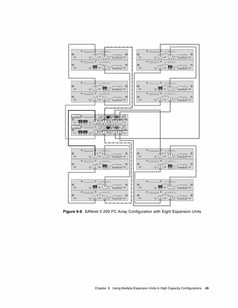
Figure 6-8 SANnet II 200 FC Array Configuration with Eight Expansion Units
Chapter 6 Using Multiple Expansion Units in High Capacity Configurations 45

46 SANnet II 200 FC and SATA Array Best Practices Manual • July 2005
CHAPTER 7
SANnet II 200 SATA Array High-Capacity Configurations
SANnet II 200 SATA arrays allow the connection of up to five expansion units to support a maximum of 72 disks. You can create large configurations beyond 12 disks if you use the guidelines in this section.
Note – Do not use a SANnet II 200 SATA array to store single instances of data. It is more suitable for use in configurations where the array has a backup or archival role.
See “SANnet II 200 FC Array High-Capacity Configurations” on page 37 for information about adding more than two expansion units to a SANnet II 200 FC array.
The use of a full-fabric SAN configuration is highly recommended for host connections, as shown in “Full-Duplex SAN Configurations” on page 29.
Refer to the SANnet II Family FRU Installation Guide for information about supported disk drives, cables, SFPs, and other user-replaceable items.
Note – The following high-capacity configurations illustrate cabling techniques for drive ports. They must be combined with a standard configuration described in this document, such as shown in “Redundant Point-to-Point SAN Configurations” on page 33. They must also be used with the network applications appropriate to the array, as summarized in Chapter 1 and described in more detail in the SANnet II 200 FC, SATA, and SATA SE Array Installation, Operations, and Service Manual.
For additional late-breaking technical and configuration details about SATA disk technology and the SANnet II 200 SATA array, be sure to check the release notes.
47
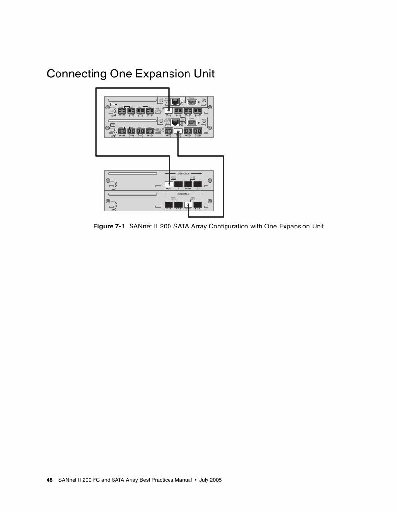
Connecting One Expansion Unit
Figure 7-1 SANnet II 200 SATA Array Configuration with One Expansion Unit
H/D/RCC
H/D/RCC
48 SANnet II 200 FC and SATA Array Best Practices Manual • July 2005
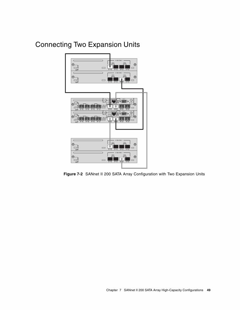
Connecting Two Expansion Units
Figure 7-2 SANnet II 200 SATA Array Configuration with Two Expansion Units
H/D/RCC
H/D/RCC
Chapter 7 SANnet II 200 SATA Array High-Capacity Configurations 49
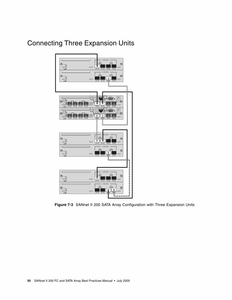
Connecting Three Expansion Units
Figure 7-3 SANnet II 200 SATA Array Configuration with Three Expansion Units
H/D/RCC
H/D/RCC
50 SANnet II 200 FC and SATA Array Best Practices Manual • July 2005
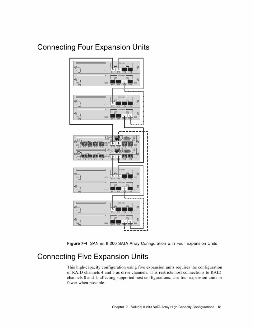
Connecting Four Expansion Units
Figure 7-4 SANnet II 200 SATA Array Configuration with Four Expansion Units
Connecting Five Expansion UnitsThis high-capacity configuration using five expansion units requires the configuration of RAID channels 4 and 5 as drive channels. This restricts host connections to RAID channels 0 and 1, affecting supported host configurations. Use four expansion units or fewer when possible.
H/D/RCC
H/D/RCC
Chapter 7 SANnet II 200 SATA Array High-Capacity Configurations 51
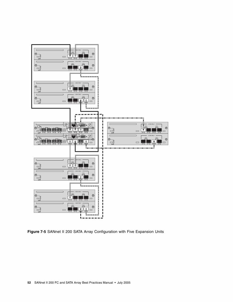
Figure 7-5 SANnet II 200 SATA Array Configuration with Five Expansion Units
H/D/RCC
H/D/RCC
52 SANnet II 200 FC and SATA Array Best Practices Manual • July 2005
CHAPTER 8
Combining SANnet II 200 FC Arrays and SANnet II 200 SATA Expansion Units
You can connect both SANnet II 200 FC and SANnet II 200 SATA expansion units to a SANnet II 200 FC RAID array. This makes it possible to combine fast, reliable online data processing with less expensive near-line storage and backup.
See the release notes and the SANnet II 200 FC, SATA, and SATA SE Array Installation, Operations, and Service Manual for information about appropriate uses for these products and limitations on their use.
If you are using a SANnet II 200 FC array and want to add SANnet II 200 SATA expansion units, as many as five expansion units can be added. These can include any combination of SANnet II 200 FC expansion units and SANnet II 200 SATA expansion units. In contrast, if using only SANnet II 200 FC expansion units, a maximum of eight expansion units can be added to a SANnet II 200 FC array.
Restrictions on the Use of Expansion-Unit Combinations
Some practices that involve combining SANnet II 200 SATA expansion units with SANnet II 200 FC arrays and expansion units are not supported. Observe the following restrictions.■ Connect SANnet II 200 SATA expansion units only to host channels on the
SANnet II 200 FC array that have been converted to drive channels. Do not use channels 2 and 3 for SANnet II 200 SATA expansion units. For information about converting host channels to drive channels, refer to the SANnet II Family RAID Firmware User’s Guide for your array.
■ Do not combine SANnet II 200 FC drives and SANnet II 200 SATA drives on the same Fibre Channel loop. Use them only on separate loops.
■ Manage and monitor SATA arrays and expansion units out-of-band. Due to the slower performance of SATA drives, managing and monitoring SANnet II 200 SATA arrays and expansion units using in-band connections may result in contention between I/O operations and monitoring operations.
53
Connecting Three FC Expansion Units and Two SATA Expansion Units to a SANnet II 200 FC RAID Array
Under certain conditions it may be appropriate to combine SANnet II 200 FC expansion units and SANnet II 200 SATA expansion units attached to a SANnet II 200 FC RAID array. For instance, in a transaction-processing environment a configuration such as the one shown in Figure 8-1 might be appropriate.■ During the day, logical drives using only FC disks could be dedicated to mission-
critical online transaction processing I/O operations.■ After working hours, other logical drives composed of the slower SATA drives in
the two SANnet II 200 SATA expansion units could be used to backup the transaction data from the FC logical drives. They could also be used for onsite disk-based storage of previous days’ transactions until they could be backed up weekly to tape and stored offsite.
This sample configuration shows three SANnet II 200 FC expansion units (above the RAID array in the illustration) and two SANnet II 200 SATA expansion units (below the RAID array in the illustration). This high-capacity configuration requires the configuration of RAID channels 4 and 5 as drive channels. This restricts host connections to RAID channels 0 and 1.
Note – Do not connect SANnet II 200 SATA expansion units to the SANnet II 200 FC RAID array’s dedicated drive channels or to channels also used by SANnet II 200 FC expansion units.
54 SANnet II 200 FC and SATA Array Best Practices Manual • July 2005
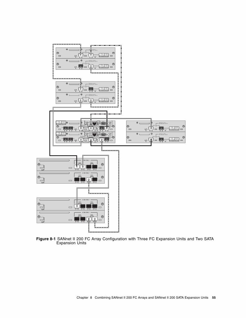
Figure 8-1 SANnet II 200 FC Array Configuration with Three FC Expansion Units and Two SATA Expansion Units
Chapter 8 Combining SANnet II 200 FC Arrays and SANnet II 200 SATA Expansion Units 55

56 SANnet II 200 FC and SATA Array Best Practices Manual • July 2005


![データコレクター FC-200/FC-250 監督さん.Ⅴ›£督さんV(GNSS...FC-200/250「監督さん.Ⅴ」 [4.GNSSオプション編] 3 基本設定 ここでは全現場共通の設定を行います。](https://img.pdfslide.net/doc/110x75/5f6e09eaa51b7a0618014c63/ffff-fci200ifci250-cca-ciignss.jpg)