Embed Size (px)
Citation preview
SAP 2012
The Government’s Standard Assessment Procedure for Energy Rating of Dwellings
2012 edition
This document describes SAP 2012 version 9.92, dated October 2013. SAP assessors and other users should ensure that they are using the latest version of the document. Information on this and any updates will be published on the website below.
Published on behalf of DECC by: BRE Garston, Watford, WD25 9XX Enquiries to [email protected] www.bre.co.uk/sap2012 © Crown copyright 2014 rev February 2014 to include TER calculation for Wales rev June 2014 to include RdSAP 2012

Published on behalf of DECC by: BRE, Garston, Watford, WD25 9XX © Crown copyright 2014
SAP 2012 version 9.92 (October 2013)
1
Contents
SUMMARY 5 INTRODUCTION 5 SCOPE OF THE SAP PROCEDURE 6 GENERAL PRINCIPLES 6 CALCULATION PROCEDURE AND CONVENTIONS 8
1 Dwelling dimensions 8 2 Ventilation rate 10
2.1 Chimneys and flues 10 2.2 Fans and passive vents 11 2.3 Pressurisation test 11 2.4 Draught lobby 11 2.5 Sheltered Sides 11 2.6 Mechanical ventilation 12
3 Heat transmission 14 3.1 U-values of opaque elements 14 3.2 Window U-values 15 3.3 U-values of elements adjacent to an unheated space 15 3.4 Thermal bridging 19 3.5 Dwellings that are part of larger premises 19 3.6 Curtain walling 19 3.7 Party walls 19
4 Domestic hot water 20 4.1 Distribution loss 20 4.2 Storage loss 20 4.3 Community schemes 21 4.4 Solar collector 21 4.5 Alternative DHW heating systems 21
5 Internal gains 22 6 Solar gains and utilisation factor 22
6.1 Solar gains for openings 22 6.2 Openings for which solar gain is included 22 6.3 More than one glazing type 23 6.4 Utilisation factor 23 6.5 Solar gain in summer 23
7 Mean internal temperature 23 7.1 Living area 23
8 Climatic data 23 9 Space heating requirement 23
9.1 Heating systems 24 9.2 Heating system efficiency (space and DHW) 24 9.3 Temperature of heat emitters for condensing boilers and heat pumps 27 9.4 Heating controls 28
10 Space cooling requirement 31 11 Fabric Energy Efficiency 31 12 Total energy use and fuel costs 32
12.1 Energy use 32 12.2 Fuel prices 32 12.3 Electricity tariff 32
SAP 2012 version 9.92 (October 2013)
2
12.4 Main fuel types 33 12.5 Secondary fuel types 34 12.6 Water heating fuel types 34 12.7 Electricity for pumps and fans 35 12.8 Electricity for lighting 35
13 Energy cost rating 35 14 Carbon dioxide emissions and primary energy 35 15 Building regulations and dwelling emissions rate (DER) 36 16 CO2 emissions associated with appliances and cooking and site-wide electricity generation technologies 37
References 38 List of standards referred to in this document 38
Appendix A : Main and secondary heating systems 40 Appendix B : Gas and oil boiler systems, boilers with a thermal store, and range cooker boilers 44 Appendix C : Community heating, including schemes with Combined Heat and Power (CHP) and schemes that recover heat from power stations 47 Appendix D : Method of determining seasonal efficiency values for gas, oil and solid fuel boilers 51 Appendix E : Method of determining seasonal efficiency for gas, oil and solid fuel room heaters 63 Appendix F : Electric CPSUs 65 Appendix G : Flue gas heat recovery systems and Waste water heat recovery systems 66 Appendix H : Solar water heating 74 Appendix I (not used) 79 Appendix J (not used, see D7 for solid fuel boilers) 79 Appendix K : Thermal bridging 80 Appendix L : Energy for lighting and electrical appliances 83 Appendix M : Energy from Photovoltaic (PV) technology, small and micro wind turbines and small-scale hydro-electric generators 86 Appendix N : Micro-cogeneration (or micro-CHP) and heat pumps 90 Appendix O (not used) 101 Appendix P : Assessment of internal temperature in summer 102 Appendix Q : Special features and specific data 107 Appendix R : Reference values 108 Appendix S : Reduced Data SAP for existing dwellings 113 Appendix T : Improvement measures for Energy Performance Certificates 162 Appendix U : Climate data 172
SAP WORKSHEET (Version 9.92) 179
Table 1a: Number of days in month, nm 194
Table 1b: Occupancy and domestic hot water usage 194 Table 1c: Monthly factors for hot water use 194 Table 1d: Temperature rise of hot water drawn off (∆Tm, in K) 194
SAP 2012 version 9.92 (October 2013)
3
Table 1e: Heat capacities for some common constructions 195 Table 1f: Thermal mass parameter 196 Table 2: Hot water storage loss factor 197 Table 2a: Volume factor for cylinders and storage combis 197 Table 2b: Factors applied to losses for cylinders, thermal stores and CPSUs, and to storage combi boilers not tested to EN 13203-2 or OPS 26 198 Table 3: Primary circuit loss 199 Table 3a: Additional losses for combi boilers not tested to EN 13203-2 or OPS 26 199 Table 3b: Losses for combi boilers tested to EN 13203-2 or OPS 26, schedule 2 only 200 Table 3c: Losses for combi boilers tested to EN 13203-2 or OPS 26, two schedules 201 Table 4a: Heating systems (space and water) 202 Table 4b: Seasonal efficiency for gas and oil boilers 207 Table 4c: Efficiency adjustments 208 Table 4d: Heating type and responsiveness for wet systems depending on heat emitter 209 Table 4e: Heating system controls 210 Table 4f: Electricity for fans and pumps and electric keep-hot facility 213 Table 4g: Default specific fan power for mechanical ventilation systems and heat recovery efficiency for MVHR systems 214 Table 4h: In-use factors for mechanical ventilation systems 214 Table 5: Internal heat gains 215 Table 5a: Gains from pumps and fans 215 Table 6b: Transmittance factors for glazing 216 Table 6c: Frame factors for windows and glazed doors 216 Table 6d: Solar and light access factors 216 Table 6e: Default U-values (W/m2K) for windows, doors and roof windows 217 Table 9: Heating periods and heating temperatures 219 Table 9a: Utilisation factor for heating 219 Table 9b: Temperature reduction when heating is off 220 Table 9c: Heating requirement 220 Table 10a: Utilisation factor for cooling 222 Table 10b: Cooling requirement 222 Table 10c: Energy Efficiency Ratio (EER) and System Energy Efficiency Ratio (SEER) 223 Table 11: Fraction of heat supplied by secondary heating systems 224 Table 12: Fuel prices, emission factors and primary energy factors 225 Table 12a: High-rate fractions for systems using 7-hour and 10-hour tariffs 227 Table 12b: Solid Fuels 228 Table 12c: Distribution loss factor for group and community heating schemes 229 Table 13: High-rate fraction for electric DHW heating 230 Table 14: Rating bands 231 Table 15: Relationship between SAP 2009 ratings and SAP 2012 ratings 231

SAP 2012 version 9.92 (October 2013)
4
Table 16: Relationship between Environmental Impact ratings, SAP 2009 and SAP 2012 232

SAP 2012 version 9.92 (October 2013)
5
SUMMARY This manual describes the Government’s Standard Assessment Procedure (SAP) for assessing the energy performance of dwellings. The indicators of energy performance are Fabric Energy Efficiency (FEE), energy consumption per unit floor area, energy cost rating (the SAP rating), Environmental Impact rating based on CO2 emissions (the EI rating) and Dwelling CO2 Emission Rate (DER). The SAP rating is based on the energy costs associated with space heating, water heating, ventilation and lighting, less cost savings from energy generation technologies. It is adjusted for floor area so that it is essentially independent of dwelling size for a given built form. The SAP rating is expressed on a scale of 1 to 100, the higher the number the lower the running costs. The Environmental Impact rating is based on the annual CO2 emissions associated with space heating, water heating, ventilation and lighting, less the emissions saved by energy generation technologies. It is adjusted for floor area so that it is essentially independent of dwelling size for a given built form. The Environmental Impact rating is expressed on a scale of 1 to 100, the higher the number the better the standard. The Dwelling CO2 Emission Rate is a similar indicator to the Environmental Impact rating, which is used for the purposes of compliance with building regulations. It is equal to the annual CO2 emissions per unit floor area for space heating, water heating, ventilation and lighting, less the emissions saved by energy generation technologies, expressed in kg/m²/year. The method of calculating the energy performance and the ratings is set out in the form of a worksheet, accompanied by a series of tables. The methodology is compliant with the Energy Performance of Buildings Directive. The calculation should be carried out using a computer program that implements the worksheet and is approved for SAP calculations (BRE approves SAP software used within schemes recognised by government on behalf of the Department for Energy and Climate Change; the Department for Communities and Local Government; the Scottish Government; the National Assembly for Wales; and the Department of Finance and Personnel).
INTRODUCTION The Standard Assessment Procedure (SAP) is adopted by Government as the UK methodology for calculating the energy performance of dwellings. The calculation is based on the energy balance taking into account a range of factors that contribute to energy efficiency: • materials used for construction of the dwelling • thermal insulation of the building fabric • air leakage ventilation characteristics of the dwelling, and ventilation equipment • efficiency and control of the heating system(s) • solar gains through openings of the dwelling • the fuel used to provide space and water heating, ventilation and lighting • energy for space cooling, if applicable • renewable energy technologies The calculation is independent of factors related to the individual characteristics of the household occupying the dwelling when the rating is calculated, for example: • household size and composition; • ownership and efficiency of particular domestic electrical appliances; • individual heating patterns and temperatures. The procedure used for the calculation is based on the BRE Domestic Energy Model (BREDEM[ 1,2,3,4,5]), which provides a framework for the calculation of energy use in dwellings. The procedure is consistent with the standard BS EN ISO 13790.
SAP 2012 version 9.92 (October 2013)
6
The Standard Assessment Procedure was first published by the then DOE and BRE in 1993 and in amended form in 1994, and conventions to be used with it were published in 1996 and amended in 1997. Revised versions were published in 1998, 2001, 2005 and 2009.
The present edition is SAP 2012 in which: - climatic data has been extended to allow calculations using regional weather - an allowance for height above sea level is incorporated into external temperature data - CO2 emission factors have been extensively revised - fuel price and primary energy factors have been revised - the options for heat losses from primary pipework have been extended At present the effect of feed-in tariffs has not been factored into SAP. This is under consideration and the government will consult on proposals.
SCOPE OF THE SAP PROCEDURE The procedure is applicable to self-contained dwellings (of any size and any age). For flats, it applies to the individual flat and does not include common areas such as access corridors. Note: Common areas of blocks of flats such as heated access corridors, and other buildings (even though used for residential purposes, e.g. nursing homes) are assessed using procedures for non-domestic buildings. Where part of an accommodation unit is used for commercial purposes (e.g. as an office or shop), this part should be included as part of the dwelling if the commercial part could revert to domestic use on a change of occupancy. That would be applicable where: - there is direct access between the commercial part and the remainder of the accommodation, and - all is contained within the same thermal envelope, and - the living accommodation occupies a substantial proportion of the whole accommodation unit. Where a self-contained dwelling is part of a substantially larger building, and the remainder of the building would not be expected to revert to domestic use, the dwelling is assessed by SAP and the remainder by procedures for non-domestic buildings. SAP is a methodology for calculating energy use and the associated running costs and CO2 emissions. It does not set any standards or limitations on data. For SAP calculations dwellings have a standard occupancy and usage pattern, which are typical values of quantities that in practice vary substantially between dwellings of similar size and type. The occupancy assumed for SAP calculations is not suitable for design purposes, for example of hot water systems.
GENERAL PRINCIPLES Input precision and rounding Data should be entered into calculation software as accurately as possible, although it is unnecessary to go beyond 3 significant figures (and some product data may only be available to lesser precision). Input data Various tables of performance data are provided as part of this document. The tables are used when specific performance information on the product or system is not available. However, when specific performance information is available for the following items, it should be used in preference to data from the tables, particularly in the new build context. A set of conventions is published separately on www.bre.co.uk/sap2009 which should be used in conjunction with this document in connection with data acquisition and assembly for input to a SAP calculation. U-values – walls, floors, roofs For new build, U-values should be calculated on the basis of the actual construction.
SAP 2012 version 9.92 (October 2013)
7
Thermal mass The Thermal Mass Parameter (TMP) is required for heating and cooling calculations. It is defined as the sum of (area times heat capacity) over all construction elements divided by total floor area. It can be obtained from the actual construction elements of walls, floors and roofs (including party and internal walls, floors and ceilings). For further details see Table 1e. Linear thermal transmittance (Ψ-values) Ψ-values are used for thermal bridging. There are three possibilities. a) The use of a global factor, which is multiplied by the total exposed surface area, as described in
Appendix K. b) On the basis of the length of each junction and the default Ψ-values in Table K1. c) On the basis of the length of each junction and user-supplied Ψ-values. It is not necessary to supply
Ψ-value for each junction type – values from Table K1 can be mixed with user-supplied values. Window data Window U-values and g-values (total solar energy transmittance) can be from a certified window energy rating1 or manufacturers’ declaration. Both values are needed (for the calculation of respectively heat loss and solar gain). Values of light transmittance (gL) are given in Table 6b for calculation of lighting energy requirements as set out in Appendix L. For new dwellings and other cases where solar gain provides a significant part of heating requirements the frame factor (representing the glazed fraction of the window) is important in determining solar gain. Frame factors should be assigned per window (or per group of similar windows) particularly where window areas differ on different facades on the dwelling. Default values are given in Table 6c. Boiler efficiency – gas, oil and solid fuel Boiler efficiency can be from the Product Characteristics Database. Warm air heating systems (not heat pump) Efficiency can be from the Product Characteristics Database. Heat pumps Data for heat pumps can be obtained from the Products Characteristics Database and applied via the procedures in Appendix N. Efficiency of gas/oil/solid fuel fires and room heaters Efficiency can be from a manufacturer’s declaration given in terms of E2. Standing loss – cylinders, thermal stores and CPSUs (includes both gas and electric CPSUs) The manufacturer’s declared loss, obtained in terms of the applicable British Standard and expressed in kWh/day, can be used in place of data from Table 2. (Tables 2a and 2b are applied to declared loss as well as to loss from Table 2). Pressure test result The result of a pressure test, where available, is used instead of the default calculations of infiltration. In the case of a dwelling not yet built, a design value of air permeability can be used subject to the requirements of building regulations that apply in the administration where the dwelling will be constructed. Solar collector performance The zero-loss collector efficiency and the collector’s heat loss coefficients can be used if obtained from test results. Specific fan power and ventilation heat exchanger efficiency Measured values of specific fan power for these mechanical ventilation systems: - positive input ventilation from outside (not loft) 1 Operated by the British Fenestration Rating Council
SAP 2012 version 9.92 (October 2013)
8
- mechanical extract - balanced supply and extract and of heat exchanger efficiency for MVHR systems, can be used in place of the default values in Table 4g for those systems that are listed in the Product Characteristics Database. Existing properties The SAP calculation procedure for existing properties follows that for new dwellings. However, some of the data items are usually defaulted or inferred. For further details see Appendix S of SAP 2009 (version 9.91, April 2012). The calculation is concerned with the assessment of the dwelling itself, as used by standard or typical occupants, and not affected by the way current occupants might use it. Thus, for example, the living area is based on the original design concept and not on the rooms the current occupants heat.
CALCULATION PROCEDURE AND CONVENTIONS The method of calculating the energy performance is set out in the form of a worksheet, accompanied by a series of tables. A calculation should follow the numbered entries in the worksheet sequentially. Some entries are obtained by carrying forward earlier entries, other entries are obtained, using linear interpolation where appropriate, by reference to Tables 1 to 14 or from user-supplied data. The following notes on calculations and conventions should be read in conjunction with the worksheet. The worksheet is intended as a form of describing the calculation, to be used for implementing the calculation into computer software, rather than for manual calculations.
1 DWELLING DIMENSIONS The boundary of the heated space consists of all the building elements separating it from external environment or from adjacent dwellings or unheated spaces. Any internal elements (internal partition walls or intermediate floors within the dwelling) are disregarded for the purposes of establishing areas. Dimensions refer to the inner surfaces of the elements bounding the dwelling. Thus floor dimensions are obtained by measuring between the inner surfaces of the external or party walls, disregarding the presence of any internal walls. Storey height is the total height between the ceiling surface of a given storey and the ceiling surface of the storey below. For a single storey dwelling (including a single storey flat), or the lowest floor of a dwelling with more than one storey, the measurement should be from floor surface to ceiling surface. However any suspended ceiling should be disregarded. Where the room height varies, such as in a room-in-roof, the storey height should be an average based on the volume of the space and the internal floor area (plus the thickness of the floor if it is the upper storey of a house). Floor area should be measured as the actual floor area, i.e. if the height of a room extends to two storeys or more only the actual accessible floor area should be used for the calculations. However, as an exception to this rule in the case of stairs, the floor area should be measured as if there were no stairs but a floor in their place at each level. In general, rooms and other spaces, such as built-in cupboards, should be included in the calculation of the floor area where these are directly accessible from the occupied area of the dwelling. However unheated spaces clearly divided from the dwelling should not be included. The following provides specific guidance: Porches:
• should be included if heated by fixed heating devices; • should not be included if unheated and external. In this context ‘external’ means an addition
protruding from the line of the external wall of the dwelling; • should not be included if unheated and thermally separated from the dwelling.
SAP 2012 version 9.92 (October 2013)
9
Conservatories: • should not be included if they are separated from the dwelling according to the definition in
3.3.3 • should be included as part of the dwelling if they are not separated.
Store rooms and utility rooms:
• should be included if they are directly accessible from the occupied area of the dwelling, whether heated or not;
• should not be included if they are unheated and accessible only via a separate external door. Basements:
• should be included if accessed via a permanent fixed staircase and either:- - basement is heated via fixed heat emitters, or - basement is open to the rest of the dwelling..
Garages:
• should be included if heating is provided within the garage from the main central heating system;
• should not be included where the garage is thermally separated from the dwelling and is not heated by the central heating system
Attics:
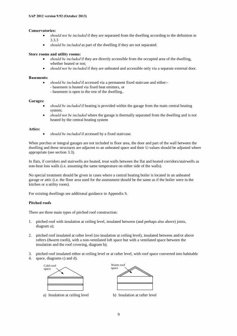
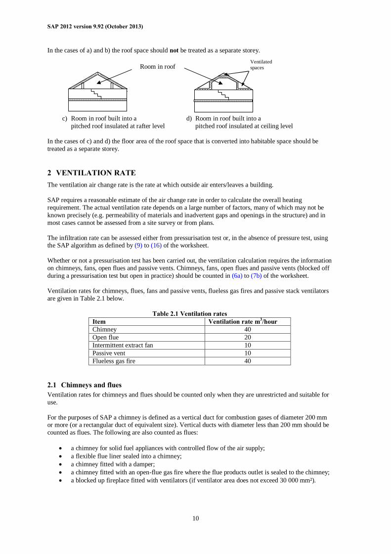
• should be included if accessed by a fixed staircase. When porches or integral garages are not included in floor area, the door and part of the wall between the dwelling and these structures are adjacent to an unheated space and their U-values should be adjusted where appropriate (see section 3.3). In flats, if corridors and stairwells are heated, treat walls between the flat and heated corridors/stairwells as non-heat loss walls (i.e. assuming the same temperature on either side of the walls). No special treatment should be given in cases where a central heating boiler is located in an unheated garage or attic (i.e. the floor area used for the assessment should be the same as if the boiler were in the kitchen or a utility room). For existing dwellings see additional guidance in Appendix S. Pitched roofs There are three main types of pitched roof construction: 1. pitched roof with insulation at ceiling level, insulated between (and perhaps also above) joists,
diagram a); 2. pitched roof insulated at rafter level (no insulation at ceiling level), insulated between and/or above
rafters (“warm roof”), with a non-ventilated loft space but with a ventilated space between the insulation and the roof covering, diagram b);
3. pitched roof insulated either at ceiling level or at rafter level, with roof space converted into habitable 4. space, diagrams c) and d). a) Insulation at ceiling level b) Insulation at rafter level
Cold roof space
Warm roof space
SAP 2012 version 9.92 (October 2013)
10
In the cases of a) and b) the roof space should not be treated as a separate storey. c) Room in roof built into a d) Room in roof built into a pitched roof insulated at rafter level pitched roof insulated at ceiling level In the cases of c) and d) the floor area of the roof space that is converted into habitable space should be treated as a separate storey.
2 VENTILATION RATE The ventilation air change rate is the rate at which outside air enters/leaves a building. SAP requires a reasonable estimate of the air change rate in order to calculate the overall heating requirement. The actual ventilation rate depends on a large number of factors, many of which may not be known precisely (e.g. permeability of materials and inadvertent gaps and openings in the structure) and in most cases cannot be assessed from a site survey or from plans. The infiltration rate can be assessed either from pressurisation test or, in the absence of pressure test, using the SAP algorithm as defined by (9) to (16) of the worksheet. Whether or not a pressurisation test has been carried out, the ventilation calculation requires the information on chimneys, fans, open flues and passive vents. Chimneys, fans, open flues and passive vents (blocked off during a pressurisation test but open in practice) should be counted in (6a) to (7b) of the worksheet. Ventilation rates for chimneys, flues, fans and passive vents, flueless gas fires and passive stack ventilators are given in Table 2.1 below.
Table 2.1 Ventilation rates Item Ventilation rate m3/hour Chimney 40 Open flue 20 Intermittent extract fan 10 Passive vent 10 Flueless gas fire 40
2.1 Chimneys and flues Ventilation rates for chimneys and flues should be counted only when they are unrestricted and suitable for use. For the purposes of SAP a chimney is defined as a vertical duct for combustion gases of diameter 200 mm or more (or a rectangular duct of equivalent size). Vertical ducts with diameter less than 200 mm should be counted as flues. The following are also counted as flues:
• a chimney for solid fuel appliances with controlled flow of the air supply; • a flexible flue liner sealed into a chimney; • a chimney fitted with a damper; • a chimney fitted with an open-flue gas fire where the flue products outlet is sealed to the chimney; • a blocked up fireplace fitted with ventilators (if ventilator area does not exceed 30 000 mm²).
Ventilated spaces Room in roof
SAP 2012 version 9.92 (October 2013)
11
Ventilation rates should be included only for open flues; they should not be included for room-sealed boilers or room heaters. Ventilation rates for specific closed appliances may be introduced.
2.2 Fans and passive vents Intermittent-running extract fans which exhaust air (typically from the kitchen and bathroom), including cooker hoods and other independent extractor fans, should be included in the ‘number of fans’ category. For continuously running fans see section 2.6. Passive stack ventilators (passive vents) are an alternative to extract fans. Such systems comprise extract grilles connected to ridge terminals by ducts. Such systems should be supplied with air bricks or trickle vents for air ingress. It is the number of extract grilles that should be used in the calculation. Trickle vents or air bricks alone do not count as passive vents and should not be included in the calculation.
2.3 Pressurisation test A pressurisation test of a dwelling is carried out by installing a fan in the doorway of the principal entrance to the dwelling, sealing all flues and chimneys, and determining the air flow rate required to maintain an excess pressure of 50 pascals (Pa). The pressurisation test should be carried out in accordance with BS EN 13829. The air permeability measured in this way, q50, expressed in cubic metres per hour per square metre of envelope area is divided by 20 for use in the worksheet (to give an estimate of the air change rate at typical pressure differences). In this case (9) to (16) of the worksheet are not used.
2.4 Draught lobby A draught lobby is an arrangement of two doors that forms an airlock on the main entrance to the dwelling. To be included, the enclosed space should be at least 2 m2 (floor area), it should open into a circulation area, and the door arrangement should be such that a person with a push-chair or similar is able to close the outer door before opening the inner door. It may be heated or unheated and may provide access to a cloakroom (but it should not be counted as a draught lobby if it provides access to other parts of the dwelling). A draught lobby should only be specified if there is a draught lobby to the main entrance of the dwelling. If the main entrance has no draught lobby but, for example, a back door does, then no draught lobby should be specified. An unheated draught lobby in the form of an external porch should not be counted as part of the area of the dwelling. However, the door between the dwelling and the porch is a ‘semi-exposed’ element and its U-value should be calculated accordingly (see section 3.3). Flats with access via an unheated stairwell or corridor should be classified as having a draught lobby.
2.5 Sheltered Sides A side of a building is sheltered if there are adjacent buildings or tree-height hedges which effectively obstruct the wind on that side of the building. A side should be considered sheltered if all the following apply:
- the obstacle providing the shelter is at least as high as the ceiling of the uppermost storey of the dwelling;
- the distance between the obstacle and the dwelling is less than five times the height of the obstacle;
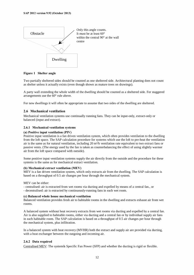
- the width of the obstacle (or the combined width of several obstacles) is such that it subtends an angle of at least 60° within the central 90° when viewed from the middle of the wall of the dwelling that faces the obstacle - see Figure 1
SAP 2012 version 9.92 (October 2013)
12
Obstacle
Dwelling
Only this angle counts.It must be at least 60°within the central 90° at the wallcentre
Figure 1 Shelter angle Two partially sheltered sides should be counted as one sheltered side. Architectural planting does not count as shelter unless it actually exists (even though shown as mature trees on drawings). A party wall extending the whole width of the dwelling should be counted as a sheltered side. For staggered arrangements use the 60° rule above. For new dwellings it will often be appropriate to assume that two sides of the dwelling are sheltered.
2.6 Mechanical ventilation Mechanical ventilation systems use continually running fans. They can be input-only, extract-only or balanced (input and extract).
2.6.1 Mechanical ventilation systems (a) Positive input ventilation (PIV) Positive input ventilation is a fan driven ventilation system, which often provides ventilation to the dwelling from the loft space. The SAP calculation procedure for systems which use the loft to pre-heat the ventilation air is the same as for natural ventilation, including 20 m³/h ventilation rate equivalent to two extract fans or passive vents. (The energy used by the fan is taken as counterbalancing the effect of using slightly warmer air from the loft space compared with outside). Some positive input ventilation systems supply the air directly from the outside and the procedure for these systems is the same as for mechanical extract ventilation.
(b) Mechanical extract ventilation (MEV) MEV is a fan driven ventilation system, which only extracts air from the dwelling. The SAP calculation is based on a throughput of 0.5 air changes per hour through the mechanical system. MEV can be either: - centralised: air is extracted from wet rooms via ducting and expelled by means of a central fan., or - decentralised: air is extracted by continuously-running fans in each wet room.
(c) Balanced whole house mechanical ventilation Balanced ventilation provides fresh air to habitable rooms in the dwelling and extracts exhaust air from wet rooms. A balanced system without heat recovery extracts from wet rooms via ducting and expelled by a central fan. Air is also supplied to habitable rooms, either via ducting and a central fan or by individual supply air fans in each habitable room. The SAP calculation is based on a throughput of 0.5 air changes per hour through the mechanical system, plus infiltration. In a balanced system with heat recovery (MVHR) both the extract and supply air are provided via ducting, with a heat exchanger between the outgoing and incoming air.
2.6.2 Data required Centralised MEV: The system’s Specific Fan Power (SFP) and whether the ducting is rigid or flexible.
SAP 2012 version 9.92 (October 2013)
13
Decentralised MEV: SFP of each fan together with the fan’s ducting arrangements (the fan can be in the ceiling of the room with a duct to the outside, or in a duct, or in a through-wall arrangement with no duct). Balanced mechanical ventilation without heat recovery. SFP taking account of all fans and whether the ducting is rigid or flexible. MVHR. SFP as a single value for the system as a whole, the efficiency of the heat exchanger, whether the ducting is rigid or flexible and whether the ducting is insulated (where outside the building’s insulated envelope). For systems that have been tested according to the SAP test procedures for mechanical ventilation systems (details at www.ncm-pcdb.org.uk/sap) the tested data from the Product Characteristics Database should be used for the calculations. Otherwise the default data in Table 4g is used.
2.6.3 In-use factors In-use factors are applied in all cases to the SFP and, for MVHR systems, heat exchanger efficiency to allow for differences in practical installations compared to the laboratory test conditions that are defined for the SAP test procedure. For SFP, the in-use factor allows for additional lengths and bends compared to the optimal test configuration and for the practicalities of setting the fan speed at the optimal value for the required flow rate. For MVHR efficiency the tested result is the efficiency of the heat exchanger itself and the in-use factor allows for losses from ductwork. In-use factors are given in Table 4h. Specific fan power and heat exchange efficiency are multiplied by the appropriate in-use factor for the purposes of SAP calculations. The factors will be updated in future as relevant to take account of research results on the practical performance of mechanical ventilation systems, and additional values applicable when the system has been installed under an approved installation scheme for mechanical ventilation if such a scheme is put in place..
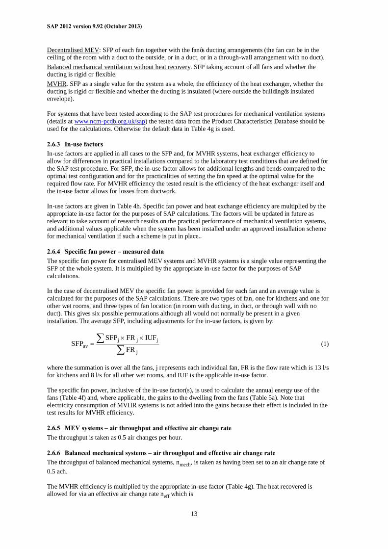
2.6.4 Specific fan power – measured data The specific fan power for centralised MEV systems and MVHR systems is a single value representing the SFP of the whole system. It is multiplied by the appropriate in-use factor for the purposes of SAP calculations. In the case of decentralised MEV the specific fan power is provided for each fan and an average value is calculated for the purposes of the SAP calculations. There are two types of fan, one for kitchens and one for other wet rooms, and three types of fan location (in room with ducting, in duct, or through wall with no duct). This gives six possible permutations although all would not normally be present in a given installation. The average SFP, including adjustments for the in-use factors, is given by:
∑∑ ××
=j
jjjav FR
IUFFRSFPSFP (1)
where the summation is over all the fans, j represents each individual fan, FR is the flow rate which is 13 l/s for kitchens and 8 l/s for all other wet rooms, and IUF is the applicable in-use factor. The specific fan power, inclusive of the in-use factor(s), is used to calculate the annual energy use of the fans (Table 4f) and, where applicable, the gains to the dwelling from the fans (Table 5a). Note that electricity consumption of MVHR systems is not added into the gains because their effect is included in the test results for MVHR efficiency.
2.6.5 MEV systems – air throughput and effective air change rate The throughput is taken as 0.5 air changes per hour.
2.6.6 Balanced mechanical systems – air throughput and effective air change rate The throughput of balanced mechanical systems, nmech, is taken as having been set to an air change rate of 0.5 ach. The MVHR efficiency is multiplied by the appropriate in-use factor (Table 4g). The heat recovered is allowed for via an effective air change rate neff which is
SAP 2012 version 9.92 (October 2013)
14
neff = nadj + nmech × (1 - η/100) (2) where nadj is the effective air change rate obtained at worksheet (22b) and η is the MVHR efficiency in % including the in-use factor. η is zero for balanced systems without heat recovery.
2.6.7 Rigid and flexible ducting Ventilation systems may be tested with rigid ducting, flexible ducting, or both, and the in-use factors for SFP depend on the ducting type. SAP calculations are done using the test data and in-use factors corresponding to the actual duct type. If data for the actual duct type are not available the default values from Table 4g are used. The data and in-use factors for rigid ductwork may be used only if all the ductwork is rigid, specifically: - for centralised systems, all ducting is rigid (although occasional flexible ducting to join components
together is permitted and is allowed for in the in-use factor); - for decentralised systems, all fans with ducting have rigid ducts. If the above conditions do not apply, the calculation is done for flexible ductwork.
2.6.8 Semi-rigid ducts Semi-rigid duct systems included in the Products Characteristics Database have demonstrated that their aerodynamic performance, when installed in a variety of configurations, is at least that for rigid ducts. Where these duct systems are used with balanced mechanical ventilation, SAP calculations use the performance data for rigid ducts.
2.6.9 Two mechanical ventilation systems Where two systems are used in the same dwelling:
a) If the two systems are identical, use the data for the system concerned corresponding to half the actual number of wet rooms. If there is an odd number of actual wet rooms, round upwards (e.g. for Kitchen+6 wet rooms use data for Kitchen+3 wet rooms).
b) If the systems are different, use an average of the data for the two systems, weighted according to the number of wet rooms served by each system. Round SFP to 2 decimal places and efficiency to nearest whole number for entry into SAP software.
c) If either of the systems are not included in the Product Characteristics Database the default data (Table 4g) applies.
3 HEAT TRANSMISSION The areas of building elements are based on the internal dimensions of surfaces bounding the dwelling. Window and door area refers to the total area of the openings, including frames. Wall area is the net area of walls after subtracting the area of windows and doors. Roof area is also net of any rooflights or windows set in the roof. Apart from party walls (see section 3.7) losses or gains to spaces in other dwellings or premises that are normally expected to be heated to the same extent and duration as the dwelling concerned are assumed to be zero (and these elements are therefore omitted from the calculation of heat losses). The calculation should allow for different types of element where their U-values differ (e.g. some windows single glazed and some double glazed, masonry main wall and timber framed wall in an extension, main roof pitched and extension roof flat).
3.1 U-values of opaque elements When the details of the construction are known, the U-values should be calculated for the floor, walls and roof. This should always be the case for new dwellings being assessed from building plans. For existing dwellings see Appendix S. U-values for walls and roofs containing repeating thermal bridges, such as timber joists between insulation, etc, should be calculated using methods based on the upper and lower resistance of elements, given in BS EN ISO 6946.
SAP 2012 version 9.92 (October 2013)
15
BS EN ISO 6946 gives the calculation that applies to components and elements consisting of thermally homogenous layers (which can include air layer) and is based in the appropriate design thermal conductivity or design thermal resistances of materials and products involved. The standard also gives an approximate method that can be used for inhomogeneous layers, except cases where an insulating layer is bridged by metal. Thermal conductivity values for common building materials can be obtained from BS EN ISO 10456 or the CIBSE Guide Section A3[6]. For specific insulation products, data should be obtained from manufacturers. U-values for ground floors and basements should be calculated using the procedure described in BS EN ISO 13370, in section A3 of the CIBSE Guide A or in the Approved Document ‘Basements for dwellings’ [7]. The thickness of loft insulation should be determined by inspection if the loft is accessible. The thickness should be measured at least as accurately as in the following list: 0, 12, 25, 50, 100, 150, 200, 250, 300 mm.
3.2 Window U-values The U-value for a window should be that for the whole window opening, including the window frame. Measurements of thermal transmittance in the case of doors and windows should be made according to BS EN ISO 12567-1. Alternatively, U-values of windows and doors may be calculated using BS EN ISO 10077-1 or BS EN ISO 10077-2. In the case of roof windows, unless the measurement or calculation has been done for the actual inclination of the roof window, adjustments as given in Notes 1 and 2 to Table 6e should be applied. Table 6e gives values that can be used in the absence of test data or calculated values. Use a value from Table 6e which corresponds most closely to the description of the actual window; interpolation should not be used in this table. The table provides default values for windows corresponding to the generic descriptions given in the table. Measured or specifically calculated values can be better than those in the table because of better frame performance, improved spacer bars and other factors. The effective window or roof window U-value to be used in worksheet (27) and (27a) takes account of the assumed use of curtains; it is calculated using the formula:
04.0U
11U
w
effective,w+
= (3)
where Uw is the window U-value calculated or measured without curtains.
3.3 U-values of elements adjacent to an unheated space The procedure for treatment of U-values of elements adjacent to unheated space is described in BS EN ISO 6946 and BS EN ISO 13789. The following procedure may be used for typical structures (no measurements are needed of the construction providing an unheated space, just select the appropriate Ru from Tables 3.1 to 3.3 below).
u0
RU1
1U+
= (4)
where: U = resultant U-value of element adjacent to unheated space, W/m2K; Uo = U-value of the element between heated and unheated spaces calculated as if there were no
unheated space adjacent to the element, W/m2K; Ru = effective thermal resistance of unheated space from the appropriate table below.
SAP 2012 version 9.92 (October 2013)
16
Ru for typical unheated structures (including garages, access corridors to flats and rooms in roof) with typical U-values of their elements are given below. These can be used when the precise details on the structure providing an unheated space are not available, or not crucial. The effect of unheated spaces, however, need not be included if the area of the element covered by the unheated space is small (i.e. less than 10% of the total exposed area of all external walls if the unheated space abuts a wall, or 10% of the total area of all heat-loss floors if the unheated space is below a floor). Consequently a door in an element abutting an unheated space would not need to have its U-value changed (unless it is part of a very small flat where the U-value of the door might make a significant contribution to the result).
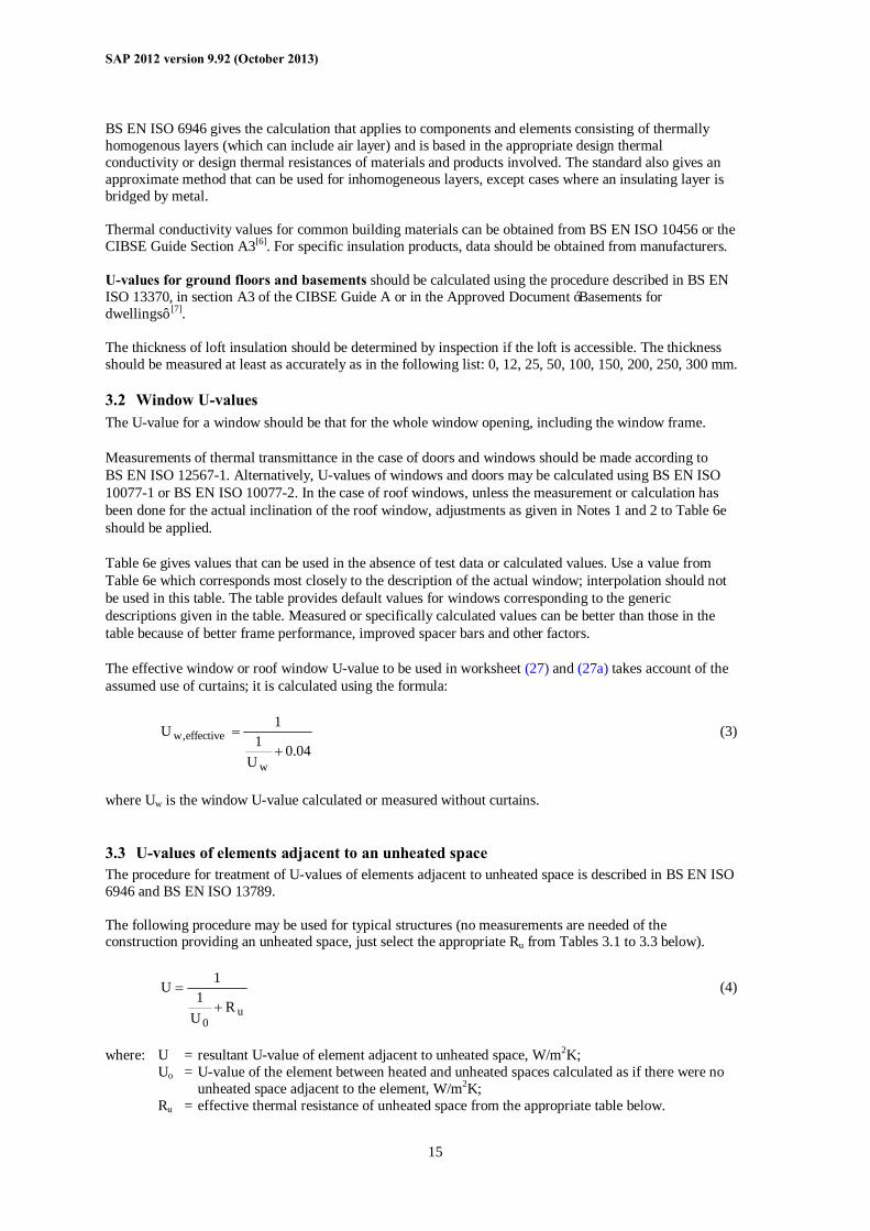
3.3.1 Garages The U-value of elements between the dwelling and an integral garage should be adjusted using Ru from Table 3.1 or Table 3.2. Attached garages (not integral) should be disregarded. Table 3.1 Ru for integral single garages (single garage is a garage for one car)
Ru for a single garage Garage type Elements between garage and dwelling Inside1 Outside2
Single fully integral
Side wall, end wall and floor
0.68
0.33
Single fully integral
One wall and floor
0.54
0.25
Single, partially integral displaced forward
Side wall, end wall and floor
0.56
0.26
Table 3.2 Ru for integral double garages (double garage is a garage for two cars)
Ru for a double garage Garage type Element between garage and dwelling Inside1 Outside2
Double garage fully integral
Side wall, end wall and floor
0.59
0.28
Double, half integral
Side wall, halves of the garage end wall and floor
0.34
n/a
Double, partially integral displaced forward
Part of the garage side wall, end wall and some floor
0.28
n/a
1inside garage – when the insulated envelope of the dwelling goes round the outside of the garage 2outside garage – when the walls separating the garage from the dwelling are the external walls
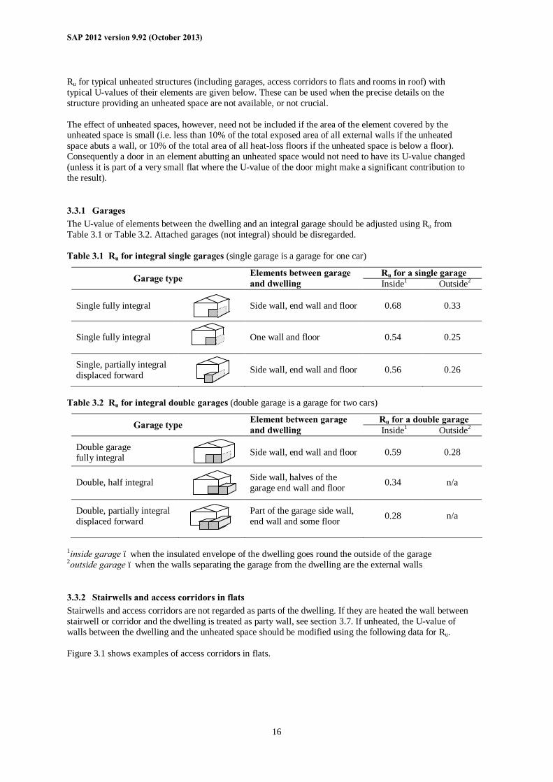
3.3.2 Stairwells and access corridors in flats Stairwells and access corridors are not regarded as parts of the dwelling. If they are heated the wall between stairwell or corridor and the dwelling is treated as party wall, see section 3.7. If unheated, the U-value of walls between the dwelling and the unheated space should be modified using the following data for Ru. Figure 3.1 shows examples of access corridors in flats.
SAP 2012 version 9.92 (October 2013)
17
FlatFacing wallnot exposed
Corridor above or below
Corridor
FlatFacing wallexposed
Figure 3.1 Access corridors The following table gives recommended values of Ru for common configurations of access corridors and stairwells.. Table 3.3 Ru for common configurations of stairwells and access corridors.
Elements between stairwell/corridor and dwelling Heat loss from corridor through:
Ru
Stairwells: Facing wall exposed 0.82 Facing wall not exposed 0.90
Access corridors: Facing wall exposed, corridors above and below facing wall, floor and ceiling 0.28 Facing wall exposed, corridor above or below facing wall, floor or ceiling 0.31 Facing wall not exposed, corridor above and below floor and ceiling 0.40 Facing wall not exposed, corridor above or below floor or ceiling 0.43
3.3.3 Conservatories Since the definition of a conservatory can vary, use the definition and any additional requirements that are appropriate to the building regulations of the administration where the dwelling is situated. Thermal separation between a dwelling and a conservatory means that they are divided by walls, floors, windows and doors for which
i) the U-values are similar to, or in the case of a newly-constructed conservatory not greater than, the U-values of the corresponding exposed elements elsewhere in the dwelling;
ii) in the case of a newly constructed conservatory, windows and doors have similar draught-proofing provisions as the exposed windows and doors elsewhere in the dwelling.
For a conservatory which is thermally separated, the calculation should be undertaken as if it were not present.
3.3.4 Other large glazed areas Any structure attached to a dwelling that is not a thermally separated conservatory according to the definitions in 3.3.3 should be treated as an integral part of the dwelling. This means that the glazed parts of the structure should be input as if they were any other glazed component (both in the heat loss section, and in the solar gain section according to orientation). See also section 3.2.
Walls adjacent to unheated space
SAP 2012 version 9.92 (October 2013)
18
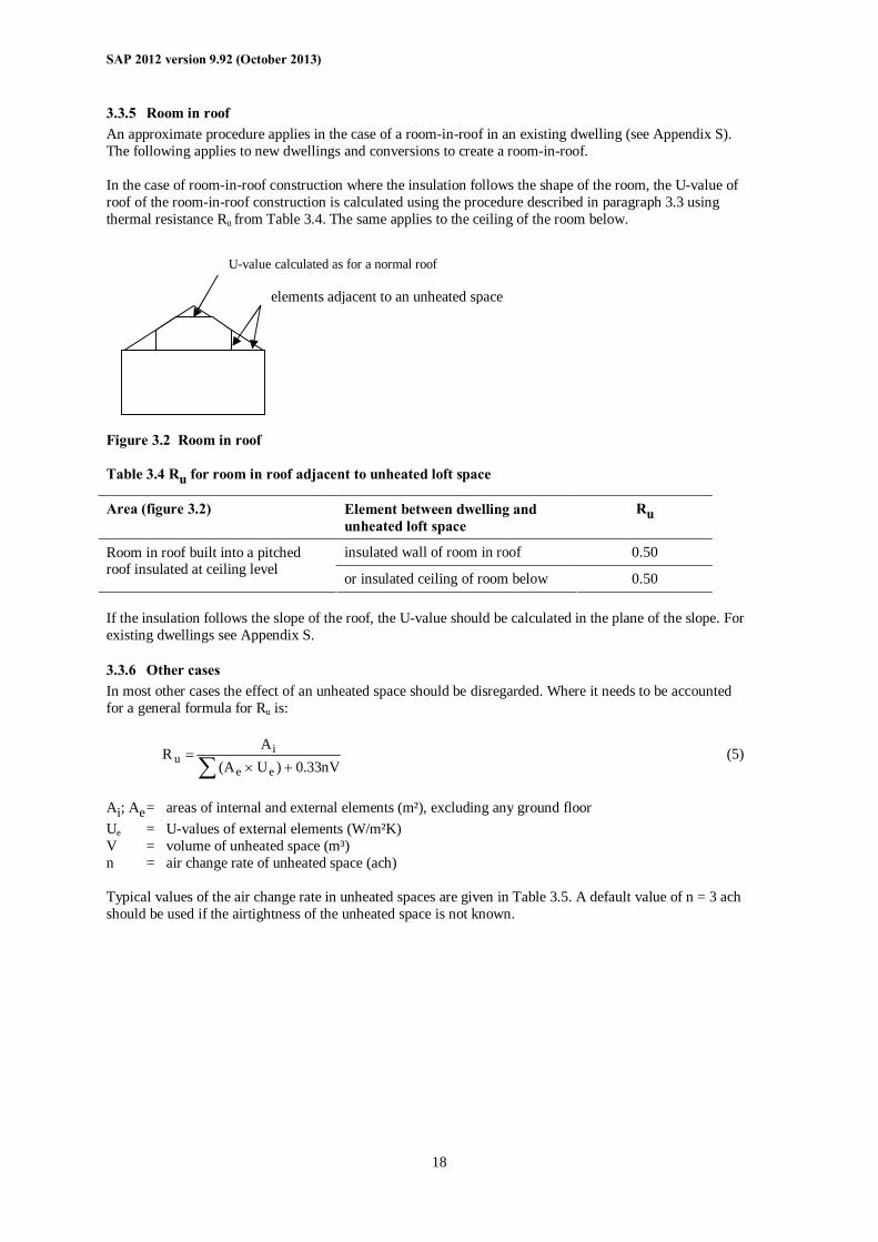
3.3.5 Room in roof An approximate procedure applies in the case of a room-in-roof in an existing dwelling (see Appendix S). The following applies to new dwellings and conversions to create a room-in-roof. In the case of room-in-roof construction where the insulation follows the shape of the room, the U-value of roof of the room-in-roof construction is calculated using the procedure described in paragraph 3.3 using thermal resistance Ru from Table 3.4. The same applies to the ceiling of the room below. Figure 3.2 Room in roof Table 3.4 Ru for room in roof adjacent to unheated loft space
Area (figure 3.2) Element between dwelling and unheated loft space
Ru
insulated wall of room in roof 0.50 Room in roof built into a pitched roof insulated at ceiling level or insulated ceiling of room below 0.50 If the insulation follows the slope of the roof, the U-value should be calculated in the plane of the slope. For existing dwellings see Appendix S.
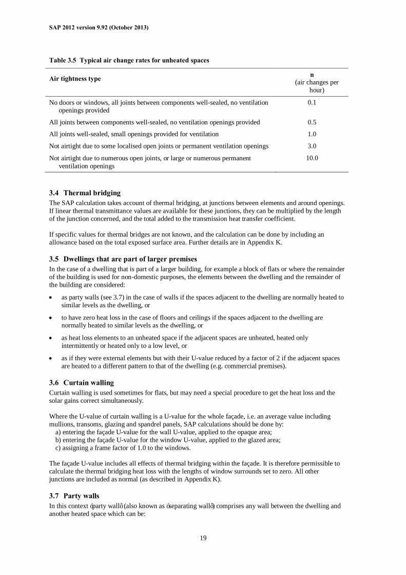
3.3.6 Other cases In most other cases the effect of an unheated space should be disregarded. Where it needs to be accounted for a general formula for Ru is:
∑ +×=
nV33.0)UA(A
Ree
iu (5)
Ai; Ae = areas of internal and external elements (m²), excluding any ground floor Ue = U-values of external elements (W/m²K) V = volume of unheated space (m³) n = air change rate of unheated space (ach) Typical values of the air change rate in unheated spaces are given in Table 3.5. A default value of n = 3 ach should be used if the airtightness of the unheated space is not known.
U-value calculated as for a normal roof
elements adjacent to an unheated space
SAP 2012 version 9.92 (October 2013)
19
Table 3.5 Typical air change rates for unheated spaces
Air tightness type n (air changes per
hour)
No doors or windows, all joints between components well-sealed, no ventilation openings provided
0.1
All joints between components well-sealed, no ventilation openings provided 0.5
All joints well-sealed, small openings provided for ventilation 1.0
Not airtight due to some localised open joints or permanent ventilation openings 3.0
Not airtight due to numerous open joints, or large or numerous permanent ventilation openings
10.0
3.4 Thermal bridging The SAP calculation takes account of thermal bridging, at junctions between elements and around openings. If linear thermal transmittance values are available for these junctions, they can be multiplied by the length of the junction concerned, and the total added to the transmission heat transfer coefficient. If specific values for thermal bridges are not known, and the calculation can be done by including an allowance based on the total exposed surface area. Further details are in Appendix K.
3.5 Dwellings that are part of larger premises In the case of a dwelling that is part of a larger building, for example a block of flats or where the remainder of the building is used for non-domestic purposes, the elements between the dwelling and the remainder of the building are considered:
• as party walls (see 3.7) in the case of walls if the spaces adjacent to the dwelling are normally heated to similar levels as the dwelling, or
• to have zero heat loss in the case of floors and ceilings if the spaces adjacent to the dwelling are normally heated to similar levels as the dwelling, or
• as heat loss elements to an unheated space if the adjacent spaces are unheated, heated only intermittently or heated only to a low level, or
• as if they were external elements but with their U-value reduced by a factor of 2 if the adjacent spaces are heated to a different pattern to that of the dwelling (e.g. commercial premises).
3.6 Curtain walling Curtain walling is used sometimes for flats, but may need a special procedure to get the heat loss and the solar gains correct simultaneously. Where the U-value of curtain walling is a U-value for the whole façade, i.e. an average value including mullions, transoms, glazing and spandrel panels, SAP calculations should be done by:
a) entering the façade U-value for the wall U-value, applied to the opaque area; b) entering the façade U-value for the window U-value, applied to the glazed area; c) assigning a frame factor of 1.0 to the windows.
The façade U-value includes all effects of thermal bridging within the façade. It is therefore permissible to calculate the thermal bridging heat loss with the lengths of window surrounds set to zero. All other junctions are included as normal (as described in Appendix K).
3.7 Party walls In this context ‘party wall’ (also known as ‘separating wall’) comprises any wall between the dwelling and another heated space which can be:
SAP 2012 version 9.92 (October 2013)
20
- another dwelling - commercial premises - a heated corridor or stairwell in a block of flats - a heated common area Where of cavity construction a party wall can provide a mechanism for heat loss via air movement within the cavity between lower floors and the loft space and between the cavity and outside. To allow for this party walls should be assigned a U-value as follows (Table 3.6):
Table 3.6 : U-values for party walls
Party wall construction U-value (W/m²K)
Solid (including structurally insulated panel) 0.0 Unfilled cavity with no effective edge sealing 0.5 Unfilled cavity with effective sealing around all exposed edges and in line with insulation layers in abutting elements 0.2
Fully filled cavity with effective sealing at all exposed edges and in line with insulation layers in abutting elements 0.0
Where edge sealing is adopted, either on its own or in conjunction with a fully filled cavity, it must be effective in restricting air flow and be aligned with the thermal envelope. Sealing is required at top and bottom and vertically.
4 DOMESTIC HOT WATER The demand for hot water is derived from the floor area of the dwelling and is specified in Table 1b. The energy required to produce that amount of hot water is then calculated, taking account of losses in heating and storage. Heat to the dwelling from storage cylinders and distribution pipework is also estimated [‘heat gains from water heating’, (65)] so that it can be taken into account in the calculation of space heating requirements. Water can be heated by any of the systems in the water heating section of Table 4a which includes systems that provide both space and water heating and systems that provide water heating only. For systems that recover heat from waste water see Appendix G.
4.1 Distribution loss A distinction is made between instantaneous water heating, which heats water when it is required, and water heating that relies on storage of hot water in a cylinder, tank or thermal store. ‘Primary’ and ‘cylinder’ losses are not used in the calculation for instantaneous heaters. ‘Single-point’ heaters, which are located at the point of use and serve only one outlet, do not have distribution losses either. Gas multipoint water heaters and instantaneous combi boilers are also instantaneous types but, as they normally serve several outlets, they are assumed to have distribution losses.
4.2 Storage loss Stored hot water systems can either be served by an electric immersion heater or obtain heat from a boiler or a heat pump through a primary circuit. In both cases, water storage losses are incurred to an extent that depends on how well the water storage is insulated. These losses apply for: • hot water cylinders; • the store volume of storage combination boilers (where the boiler efficiency is derived from test data); • thermal stores; • combined primary storage units (CPSUs); • community heating schemes. Water storage losses are set to zero for other combi boilers and instantaneous water heaters.
SAP 2012 version 9.92 (October 2013)
21
For cylinders the preferred way of establishing cylinder losses is from measured data on the cylinder concerned, according to BS 1566. For thermal stores and CPSUs (including electric CPSUs) the preferred way of establishing heat losses is from measured data on the thermal store or CPSU concerned, according to the WMA Performance Specification for thermal stores. If measured data are not available, losses from the storage vessel should be estimated by multiplying the loss factor from Table 2 by the volume of the vessel and the volume factor from Table 2a. In all cases, the loss rate is to be multiplied by a temperature factor from Table 2b. This factor accounts for the average temperature of the cylinder or thermal store under typical operating conditions, compared to its temperature under test. For combi boilers the storage loss factor is zero if the efficiency is taken from Table 4b. The loss is to be included for a storage combination boiler if its efficiency is the manufacturer’s declared value or is obtained from the Product Characteristics Database, using the data in Tables 2, 2a and 2b (its insulation thickness and volume are also to be provided by the manufacturer or obtained from the database). For boiler systems with separate hot water storage, primary losses are incurred in transferring heat from the boiler to the storage; values for primary losses are obtained from Table 3. For a combi boiler the additional loss in Table 3a is included to allow for the draw-off of water until an adequate temperature at the taps is attained (in the case of combi boiler tested to EN 13203-2 or OPS 26 the additional loss is obtained from the test data using Table 3b or Table 3c). The efficiency of gas and oil boilers for both space and water heating is reduced by 5% if the boiler is not interlocked for space and water heating (see section 9.4.11).
4.3 Community schemes Where hot water is provided from a community heating scheme:
a) If there is a hot water cylinder within the dwelling, its size and the appropriate loss factor should be used (Tables 2 and 2a).
b) If the DHW is provided from the community scheme via a plate heat exchanger use the volume of the heat exchanger (rounded upwards to the nearest litre) and the insulation of it in Tables 2 and 2a; if there are plate heat exchangers for both space and water heating use the volume of both added together.
c) If neither of the above applies the calculation should assume a cylinder of 110 litres and loss factor of 0.0152 kWh/litre/day.
Primary circuit loss for insulated pipework and cylinderstat should be included (see Table 3). The efficiency for water heating is incorporated in the price of heat for community schemes in Table 12.
4.4 Solar collector A solar collector coupled with solar water storage reduces the fuel needed for domestic hot water (see Appendix H). The solar water storage can be either as the lower part of a multi heat source cylinder, or as a separate solar cylinder. For shared systems supplying dwellings with community heating see H2 in Appendix H.
4.5 Alternative DHW heating systems In most cases the system specified for water heating should be that intended to heat the bulk of the hot water during the course of the year. For example, an immersion heater should be disregarded if provided only for backup where the principal water heating system is from a central heating boiler, as should other devices intended for or capable of heating only limited amounts of hot water. Exceptions are (a) micro-CHP and heat pump packages assessed by Appendix N where the package provides DHW only in the heating season, and (b) solid fuel room heaters with a back boiler where an immersion heater is provided to heat water in the summer (see section 12.4.4).
SAP 2012 version 9.92 (October 2013)
22
5 INTERNAL GAINS Internal gains from lights, appliances, cooking and from the occupants of the dwelling (metabolic gains) are estimated from floor area (Table 5). Gains from central heating pumps located within the heated space and other items should be added and then included in worksheet (70)m, using the values given in Table 5a. Gains from the fans in a whole-dwelling mechanical ventilation system should be included, but no useful gains are assumed from individual extractor fans.
6 SOLAR GAINS AND UTILISATION FACTOR 6.1 Solar gains for openings The heat gain through windows and glazed doors is calculated as
Gsolar = 0.9 × Aw × S × g⊥ × FF × Z (6) where:
Gsolar is the average solar gain in watts 0.9 is a factor representing the ratio of typical average transmittance to that at normal incidence Aw is the area of an opening (a window or a glazed door), m² S is the solar flux on the applicable surface from U3 in Appendix U, W/m² g⊥ is the total solar energy transmittance factor of the glazing at normal incidence (see Table 6b) FF is the frame factor for windows and doors (fraction of opening that is glazed) Z is the solar access factor from Table 6d
Frame factors (FF) should be assigned per window (or per group of similar windows) particularly where the areas of the windows differ on different facades on the dwelling. Default values are given in Table 6c. In the case of a window certified by the British Fenestration Rating Council (BFRC), see www.bfrc.org, the quoted solar factor is gwindow which is equal to 0.9 × g⊥ × FF. The solar gain for such windows is calculated as
Gsolar =Aw × S × gwindow × Z (7) In the case of ‘arrow slit’ windows where the width of opening at the external side of the wall is substantially less than the width of the window, this should be taken into account by multiplying FF (or in the case of a BFRC-rated window, gwindow) by the ratio of the opening width at the external surface of the wall to the width of the window. Solar gains should be calculated separately for each orientation, and then totalled for use in the calculation. E/W orientation of windows may be assumed if the actual orientation is not known∗. The solar access factor describes the extent to which radiation is prevented from entering the building by nearby obstacles. The over-shading categories are dependent on how much the view of the sky through the windows is blocked. The categories are defined in Table 6d in terms of the percentage of sky obscured by obstacles (the ‘average’ category applies in many cases, and can be used for SAP calculations if the over-shading is not known ∗).
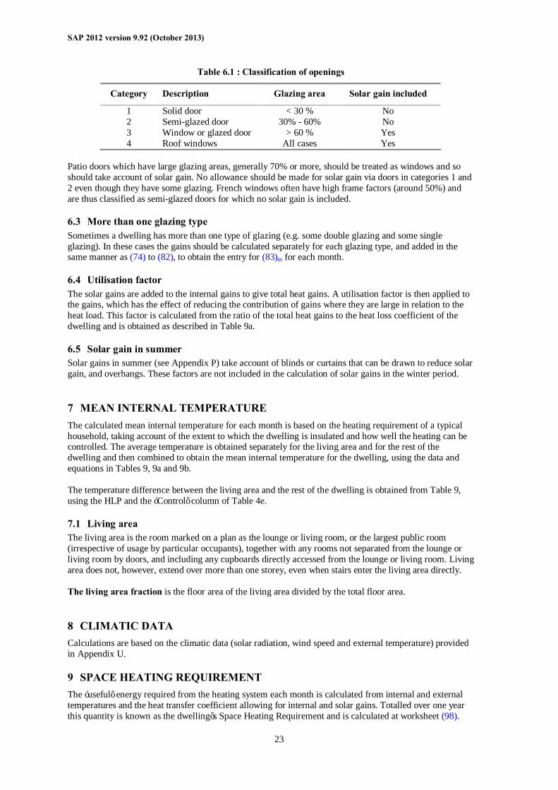
6.2 Openings for which solar gain is included Openings should be classified as windows, glazed doors or solid doors according to the percentage of glazed area (the percentage of total area of opening that is glass, i.e. excluding framing, mullions, transoms, solid panels etc.). For SAP calculations definitions in Table 6.1 apply:
∗ Subject, in the case of a new dwelling, to any requirements of building regulations that apply in the administration where the dwelling will be constructed.
SAP 2012 version 9.92 (October 2013)
23
Table 6.1 : Classification of openings
Category Description Glazing area Solar gain included
1 Solid door < 30 % No 2 Semi-glazed door 30% - 60% No 3 Window or glazed door > 60 % Yes 4 Roof windows All cases Yes
Patio doors which have large glazing areas, generally 70% or more, should be treated as windows and so should take account of solar gain. No allowance should be made for solar gain via doors in categories 1 and 2 even though they have some glazing. French windows often have high frame factors (around 50%) and are thus classified as semi-glazed doors for which no solar gain is included.
6.3 More than one glazing type Sometimes a dwelling has more than one type of glazing (e.g. some double glazing and some single glazing). In these cases the gains should be calculated separately for each glazing type, and added in the same manner as (74) to (82), to obtain the entry for (83)m for each month.
6.4 Utilisation factor The solar gains are added to the internal gains to give total heat gains. A utilisation factor is then applied to the gains, which has the effect of reducing the contribution of gains where they are large in relation to the heat load. This factor is calculated from the ratio of the total heat gains to the heat loss coefficient of the dwelling and is obtained as described in Table 9a.
6.5 Solar gain in summer Solar gains in summer (see Appendix P) take account of blinds or curtains that can be drawn to reduce solar gain, and overhangs. These factors are not included in the calculation of solar gains in the winter period.
7 MEAN INTERNAL TEMPERATURE The calculated mean internal temperature for each month is based on the heating requirement of a typical household, taking account of the extent to which the dwelling is insulated and how well the heating can be controlled. The average temperature is obtained separately for the living area and for the rest of the dwelling and then combined to obtain the mean internal temperature for the dwelling, using the data and equations in Tables 9, 9a and 9b. The temperature difference between the living area and the rest of the dwelling is obtained from Table 9, using the HLP and the ‘Control’ column of Table 4e.
7.1 Living area The living area is the room marked on a plan as the lounge or living room, or the largest public room (irrespective of usage by particular occupants), together with any rooms not separated from the lounge or living room by doors, and including any cupboards directly accessed from the lounge or living room. Living area does not, however, extend over more than one storey, even when stairs enter the living area directly. The living area fraction is the floor area of the living area divided by the total floor area.
8 CLIMATIC DATA Calculations are based on the climatic data (solar radiation, wind speed and external temperature) provided in Appendix U.
9 SPACE HEATING REQUIREMENT The ‘useful’ energy required from the heating system each month is calculated from internal and external temperatures and the heat transfer coefficient allowing for internal and solar gains. Totalled over one year this quantity is known as the dwelling’s Space Heating Requirement and is calculated at worksheet (98).
SAP 2012 version 9.92 (October 2013)
24
The quantity of fuel or electrical energy required to provide that useful energy is then calculated for each month, taking account of the efficiency of the space heating system (obtained from Product Characteristics Database or from Table 4a or 4b).
9.1 Heating systems It is assumed that the dwelling has heating systems capable of heating the entire dwelling. Calculations are on the basis of a main heating system and secondary heaters as described in Appendix A. The proportion of heat from the main and secondary systems is as given in Table 11. For a new dwelling that has no heating system specified, it should be assumed that the dwelling will be heated by direct acting electric heaters. For community heating schemes and combined heat and power, see Appendix C. A heating system supplying more than one dwelling should be regarded as a community scheme. This includes schemes for blocks of flats as well as more extended district schemes. For an electric CPSU, see Appendix F.
9.2 Heating system efficiency (space and DHW)
9.2.1 Heating systems based on a gas or oil boiler Boiler efficiency may be obtained from: a) The Product Characteristics Database; b) Table 4b of this document. The preferred source of boiler efficiency is the Product Characteristics Database, which contains boiler efficiency figures intended for use in SAP. If there is no entry in the database an indicative seasonal efficiency should be taken from Table 4b. Separate efficiencies are used for space heating and for water heating. (1) Space heating The efficiency is the winter seasonal efficiency ηwinter (from database record or Table 4b), increased if
appropriate by an increment from Table 4c. If only the SEDBUK value as used in SAP 2005 is available, obtain the winter seasonal efficiency by following the procedure in D7 then D2.2 (Appendix D). Where appropriate the space heating efficiency is incremented by the adjustment in Table 4c(1).
(2) Water heating by a boiler for which EN 13203-2 or OPS 26 data are not available If the boiler provides both space and water heating the efficiency is a combination of winter and
summer seasonal efficiencies according to the relative proportion of heat needed from the boiler for space and water heating in the month concerned:
summer
water
erintw
space
waterspacewater QQ
η+
η
+=η (8)
where
Qspace (kWh/month) is the quantity calculated at (98)m multiplied by (204) or by (205); Qwater (kWh/month) is the quantity calculated at (64)m; ηwinter and ηsummer are the winter and summer seasonal efficiencies (from database record or
Table 4b without any increment from Table 4c). If the boiler provides water heating only, ηwater = ηsummer for all months.
SAP 2012 version 9.92 (October 2013)
25
(3) Water heating by a gas or oil combi boiler where test data according to EN 13203-2 (gas) or OPS 26 (oil) are available in the database record
If the boiler provides both space and water heating use ηsummer from the database record for the boiler in equation (8) above. In this case different procedures apply to the calculation of storage loss (for a storage combi boiler) and additional combi loss, see Tables 3b and 3c.
If the boiler provides water heating only, ηwater = ηsummer for all months.
9.2.2 Gas or oil boiler with flue gas heat recovery system A condensing gas or oil boiler may be fitted with a flue gas heat recovery system. The requisite parameters are obtained from the Product Characteristics Database. The amendments to the calculation procedure are described in Appendix G.
9.2.3 Heating systems based on a gas or oil range cooker boiler For definitions see paragraph B4 (Appendix B). Boiler efficiency may be obtained from: a) The Product Characteristics Database; b) Table 4b of this document. For twin burner models the preferred source of efficiency is from the database, which contains the boiler seasonal efficiency values and case heat emission data intended for use in SAP. If there is no entry in the database or it is not of the twin burner type, indicative seasonal efficiency values should be taken from Table 4b. Separate efficiencies are used for space heating and for water heating, as described in 9.2.1 above.
9.2.4 Heating systems based on a solid fuel boiler This applies to independent solid fuel boilers, open fires with a back boiler and roomheaters with a boiler. Boiler efficiency may be obtained from: a) The Product Characteristics Database; b) Table 4a of this document. The preferred source of boiler efficiency is the Product Characteristics Database. The heating type and responsiveness is that for the applicable type of appliance given in Table 4a. If there is no entry in the database an indicative seasonal efficiency should be taken from Table 4a. Table 4a gives two sets of efficiency values for solid fuel appliances:
(A) the minimum efficiency for HETAS approved appliances; (B) default values
Values from column (A) can be used for consideration of a design where it is anticipated that a HETAS-approved appliance will be used: data for the actual appliance should be used to provide certificated energy ratings. Values from column (B) should be used for appliances, particularly those already installed in dwellings, for which efficiency data are not available. Solid fuel boiler efficiencies for open fires and closed roomheaters with boilers are the sum of the heat to water and heat directly to room. It is the designer’s responsibility to ensure that the ratio of these figures is appropriate to the property being modelled. These systems are assigned a lower responsiveness to allow for limitations on the controllability of heat output to the room.
9.2.5 Direct-acting electric boiler A direct-acting electric boiler (also known as an electric flow boiler) heats water for space heating radiators as it circulates. Possible tariffs are standard tariff, off-peak 7-hour and off-peak 10-hour. Heating control options are the same as for other radiator systems. Water heating is usually by an electric immersion. The cylinder can be within the same casing as the boiler or it can be a separate cylinder; the treatment in SAP is the same for both of these cases.
SAP 2012 version 9.92 (October 2013)
26
9.2.6 Micro-cogeneration (micro-CHP) Data are obtained from the Product Characteristics Database and used as described in Appendix N. The data provide the secondary heating fraction based on the micro-cogeneration package output power and the design heat loss of the dwelling.
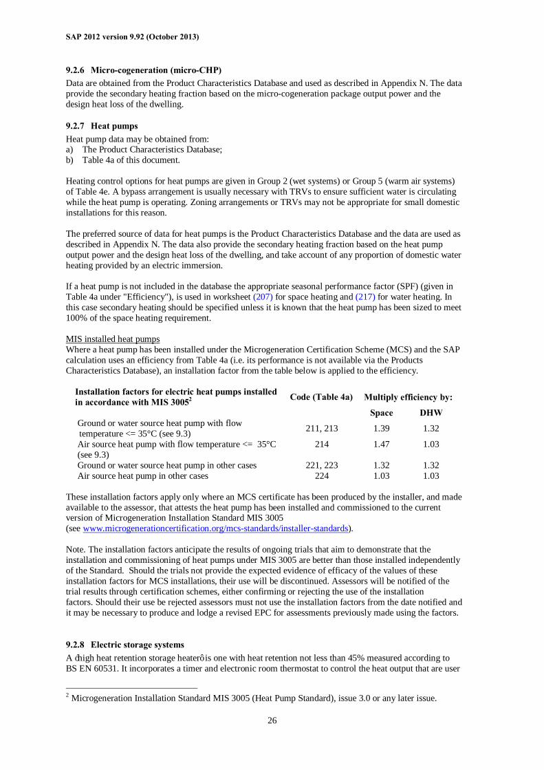
9.2.7 Heat pumps Heat pump data may be obtained from: a) The Product Characteristics Database; b) Table 4a of this document. Heating control options for heat pumps are given in Group 2 (wet systems) or Group 5 (warm air systems) of Table 4e. A bypass arrangement is usually necessary with TRVs to ensure sufficient water is circulating while the heat pump is operating. Zoning arrangements or TRVs may not be appropriate for small domestic installations for this reason. The preferred source of data for heat pumps is the Product Characteristics Database and the data are used as described in Appendix N. The data also provide the secondary heating fraction based on the heat pump output power and the design heat loss of the dwelling, and take account of any proportion of domestic water heating provided by an electric immersion. If a heat pump is not included in the database the appropriate seasonal performance factor (SPF) (given in Table 4a under "Efficiency"), is used in worksheet (207) for space heating and (217) for water heating. In this case secondary heating should be specified unless it is known that the heat pump has been sized to meet 100% of the space heating requirement. MIS installed heat pumps Where a heat pump has been installed under the Microgeneration Certification Scheme (MCS) and the SAP calculation uses an efficiency from Table 4a (i.e. its performance is not available via the Products Characteristics Database), an installation factor from the table below is applied to the efficiency.
Installation factors for electric heat pumps installed in accordance with MIS 30052 Code (Table 4a) Multiply efficiency by:
Space DHW Ground or water source heat pump with flow temperature <= 35°C (see 9.3) 211, 213 1.39 1.32
Air source heat pump with flow temperature <= 35°C (see 9.3)
214 1.47 1.03
Ground or water source heat pump in other cases 221, 223 1.32 1.32 Air source heat pump in other cases 224 1.03 1.03
These installation factors apply only where an MCS certificate has been produced by the installer, and made available to the assessor, that attests the heat pump has been installed and commissioned to the current version of Microgeneration Installation Standard MIS 3005 (see www.microgenerationcertification.org/mcs-standards/installer-standards). Note. The installation factors anticipate the results of ongoing trials that aim to demonstrate that the installation and commissioning of heat pumps under MIS 3005 are better than those installed independently of the Standard. Should the trials not provide the expected evidence of efficacy of the values of these installation factors for MCS installations, their use will be discontinued. Assessors will be notified of the trial results through certification schemes, either confirming or rejecting the use of the installation factors. Should their use be rejected assessors must not use the installation factors from the date notified and it may be necessary to produce and lodge a revised EPC for assessments previously made using the factors.
9.2.8 Electric storage systems A ‘high heat retention storage heater’ is one with heat retention not less than 45% measured according to BS EN 60531. It incorporates a timer and electronic room thermostat to control the heat output that are user
2 Microgeneration Installation Standard MIS 3005 (Heat Pump Standard), issue 3.0 or any later issue.
SAP 2012 version 9.92 (October 2013)
27
adjustable. It is also able to estimate the next day’s heating demand based on external temperature, room temperature settings and heat demand periods. Qualifying storage heaters are included in the Product Characteristics Database.
9.2.9 Room heaters Where available, manufacturer’s declared values should be used for the efficiency of gas, oil and solid fuel room heaters, certified as explained in Appendix E. Otherwise, and for other types of room heaters, the efficiency should be taken from Table 4a. Gas fires The following notes provide guidance for identifying the appropriate entry from the room heater section of Table 4a, for gas fires already installed in a dwelling. (They are not intended to classify gas fires for testing purposes.) Gas fires can be “open” or “closed” fronted. Open fronted means the fuel bed and combustion gases are not “sealed” from the room in which the gas fire is fitted. Such a fire may or may not have a glass panel in front of the fuel bed, but the glass panel will not be sealed to the front of the fire. Closed fronted means the fuel bed and combustion gases are “sealed” (generally with a glass panel sealed to the front of the fire) from the room in which the gas fire is fitted. Fuel effect gas fires can be “live fuel effect” (LFE), “inset live fuel effect” (ILFE) or “decorative fuel effect” (DFE). The products of combustion from a DFE pass unrestricted from the fire-bed to the chimney or flue; for the LFE/ILFE the products of combustion are restricted before passing into the chimney or flue. For further clarification of LFE/ILFE/DFE see clauses 3.1.2, 3.1.3 and 3.1.4 and Figure 1 of BS 7977-1:2002. Room heaters with boilers Gas, oil and solid fuel room heaters can have a boiler, which may provide either domestic hot water only or both space heating and domestic hot water. For gas back boilers, separate efficiencies apply to the boiler and to the associated room heater. This means that: - if the back boiler provides space heating, it should be defined as the main heating system, and the gas fire
should be indicated as the secondary heater; - if the back boiler provides domestic hot water only, the boiler efficiency is used for water heating and the
gas fire efficiency for space heating (gas fire as main or as secondary heater). Gas back boilers are found only behind open-flued gas fires without fan assistance. Note that the fire and the boiler share the same flue. For oil and solid fuel room heaters with boilers, the efficiency is an overall value (i.e. sum of heat to water and heat to room). This means that: - if the boiler provides space heating, the combination of boiler and room heater should be defined as the
main heating system; - if the boiler provides domestic hot water only, the overall efficiency should be used as the efficiency both
for water heating and for the room heater (room heater as main or as secondary heater).
9.2.10 Other heating systems For other systems the seasonal efficiency should be taken from Table 4a. For systems not covered by the table guidance should be sought from BRE.
9.3 Temperature of heat emitters for condensing boilers and heat pumps The efficiency of condensing boilers and heat pumps is higher when they supply heat at lower temperature. SAP calculations allow for this in the case of a low-temperature heating system. A low-temperature heating system is defined as one in which the hot water leaving the heat generator is always at a temperature not exceeding 45°C or 35°C, even on the ‘design day’ (a day with cold weather conditions chosen for calculating the maximum heat losses from the building). The definition does not
SAP 2012 version 9.92 (October 2013)
28
include heating systems in which the water temperature is lower only some of the time, such as those with weather compensation or load compensation controls, nor does it include underfloor systems in which a thermostatic mixing valve is used to blend water at a high temperature with cooler water before entering the underfloor heating system3. Low-temperature heating requires a different system design, mainly to ensure that the heat emitters (radiators, fan-assisted radiators or convectors, or underfloor heating pipes) can deliver the same amount of heat at the lower temperature as a traditional radiator system would have done at normal temperature (over 55°C). The emitters in each room must be sized correctly to ensure they are capable of achieving that. Suitable controls must also be installed to ensure the design temperature of water leaving the heat generator is not exceeded while the system is providing space heating, and the system commissioned for low temperature operation. Provided that space heating and water heating are not carried out simultaneously, separate control arrangements can apply to the water heating. Low temperature emitters apply to SAP calculations when a suitable commissioning certificate that confirms compliance with all aspects of the design, installation and commissioning requirements for low temperature operation has been signed by a suitably qualified individual and supplied to the SAP assessor. At present the only design guidance recognised by SAP is BRE Trust Report FB 59, Design of low-temperature domestic heating systems4. It includes an example design, installation and commissioning certificate. Other guidance that may become available in future might also be recognised if the same conditions and restrictions are observed.
9.3.1 Condensing boilers Condensing boilers operate at higher efficiency with lower flow and return temperatures. The space heating efficiency data in Table 4b and database records for boilers is based on the design flow temperature of the water in the heat distribution system being 55°C or higher. Where the heating system has been designed to operate at a lower temperature the space heating efficiency of a condensing boiler is increased by the applicable efficiency adjustment given in Table 4c. These adjustments apply to all heat emitter types when the design flow temperature as stated on the commissioning certificate (rounded to the nearest whole number) is less than or equal to 45°C or 35°C.
9.3.2 Heat pumps Heat pumps operate at higher efficiency with lower flow temperatures. The space heating efficiency data in 9.2.7 and Table 4a provide values for 35°C and 55°C, and database records for heat pumps provide values for 35°C, 45°C and 55°C. The default is a flow temperature of 55°C. If the heating system has been designed to operate at a lower temperature the data for lower flow temperatures are applied where the design flow water temperature as stated on the commissioning certificate (rounded to the nearest whole number) is less than or equal to 45°C or 35°C. 9.4 Heating controls The type of controls incorporated into the heating system influences the calculated energy use. This section gives specifications of the types of controls mentioned in Table 4e. ‘Heat generator’ means a device that provides heat such as a boiler or heat pump.
9.4.1 Room thermostat A sensing device to measure the air temperature within the building and switch on and off the space heating. A single target temperature may be set by the user.
9.4.2 Time switch A switch operated by a clock to control either space heating or hot water, but not both. The user chooses one or more “on” periods, usually in a daily or weekly cycle. 3 Underfloor systems may still have a mixing valve but only as a protection device 4 Available from www.brebookshop.com. A supporting calculation tool can be found at www.ncm-pcdb.org.uk/sap/lowtemperatureheating
SAP 2012 version 9.92 (October 2013)
29
9.4.3 Programmer Two switches operated by a clock to control both space heating and hot water. The user chooses one or more “on” periods, usually in a daily or weekly cycle. A mini-programmer allows space heating and hot water to be on together, or hot water alone, but not heating alone. A standard programmer uses the same time settings for space heating and hot water. A full programmer allows the time settings for space heating and hot water to be fully independent.
9.4.4 Programmable room thermostat A combined time switch and room thermostat which allows the user to set different periods with different target temperatures for space heating, usually in a daily or weekly cycle.
9.4.5 Delayed start thermostat A device or feature within a device, to delay the chosen starting time for space heating according to the temperature measured inside or outside the building.
9.4.6 Thermostatic radiator valve (TRV) A radiator valve with an air temperature sensor, used to control the heat output from the radiator by adjusting water flow.
9.4.7 Programmable TRV A TRV that allows the heating times for the room in which it is situated to be set separately from those of other rooms. Note. A system of programmable TRVs do not themselves provide a boiler interlock (see 9.4.11). Systems of programmable TRVs recognised in SAP are included in the Products Characteristics Database.
9.4.8 Communicating TRV A TRV that has the capability to respond to commands (relating to both timing and temperature level) from a central controller. Note. Systems of communicating TRVs recognised in SAP are included in the Products Characteristics Database and incorporate provision for boiler interlock for space heating (see 9.4.11).
9.4.9 Cylinder thermostat A sensing device to measure the temperature of the hot water cylinder and switch on and off the water heating. A single target temperature may be set by the user. Note: A cylinder thermostat should be assumed to be present when the domestic hot water is obtained from a community scheme, an immersion heater, a thermal store, a combi boiler or a CPSU.
9.4.10 Flow switch A flow switch is a device, which detects when there is no water flow through the system because the TRVs on all radiators are closed.
9.4.11 Boiler interlock (gas and oil boilers) This is not a physical device but an arrangement of the system controls so as to ensure that the boiler does not fire when there is no demand for heat. In a system with a combi boiler it can be achieved by fitting a room thermostat. In a system with a regular boiler it can be achieved by correct wiring interconnections between the room thermostat, cylinder thermostat, and motorised valve(s). It may also be achieved by a suitable boiler energy manager. In systems without an interlock the boiler is kept cycling even though no water is being circulated through the main radiators or to the hot water cylinder. This results in a reduction in operating efficiency and for this reason Table 4e specifies that a seasonal efficiency reduction of 5% should be made for such systems. For the purposes of the SAP, an interlocked system is one in which both the space and stored water heating are interlocked. If either is not, the 5% seasonal efficiency reduction is applied to both space and water heating; if both are interlocked no reductions are made.
SAP 2012 version 9.92 (October 2013)
30
It is also necessary to specify whether a hot water cylinder has a thermostat or not. A cylinder thermostat normally shuts down the primary circuit pump once the demand temperature in the cylinder is met. The cylinder thermostat itself might not switch off the boiler; this is only done if the pump and boiler are interlocked and so the presence of a cylinder thermostat does not in itself signify the presence of an interlock for water heating. If there is no cylinder thermostat, however, there can be no interlock since the system does not know when the demand temperature is reached. A boiler system with no cylinder thermostat or assumed cylinderstat (see 9.4.9) must therefore be considered as having no interlock. A boiler system with no room thermostat (or a device equivalent in this context, such as a flow switch or boiler energy manager), even if there is a cylinder thermostat, must be considered as having no interlock. For solid fuel boilers and electric boilers the boiler interlock question is not relevant and the efficiency values in Table 4a allow for normal operation of these appliances. For such systems there is no efficiency reduction for the absence of interlock. Note: TRVs alone (other than some communicating TRVs) do not perform the boiler interlock function and require the addition of a separate room thermostat in one room.
9.4.12 Bypass A fixed bypass is an arrangement of pipes that ensures a minimum flow rate is maintained through the heat generator. It is commonly used to ensure a minimum flow rate through a boiler or heat pump and to limit circulation pressure when alternative water paths are closed (particularly in systems with thermostatic radiator valves). A fixed bypass is achieved either by ensuring that one radiator stays open or by adding a short pipe with a fixed-position valve between the flow and return pipe. A radiator without a TRV or hand valve is a common form of fixed bypass. An automatic bypass valve controls the water flow through it according to the water pressure difference across it, typically by spring loading, so that the bypass operates only to the extent needed to maintain a minimum flow rate through the system. The control type ‘TRVs + programmer + bypass’ is a non-interlocked system in the absence of other arrangements to provide the interlock function.
9.4.13 Boiler energy manager Typically a device intended to improve boiler control using a selection of features such as weather compensation, load compensation, start control, night setback, frost protection, anti-cycling control and hot water over-ride. For the purposes of the SAP it is an equivalent to a hard-wired interlock; any other features (e.g. those in 9.4.15 or 9.4.17) are considered separately.
9.4.14 Time and temperature zone control A system of control that allows the heating times of at least two zones to be programmed independently, as well as having independent temperature control. In the case of wet systems this can be achieved by: - separate plumbing circuits, either with their own programmer, or separate channels in the same
programmer; or - programmable TRVs (9.4.7) or communicating TRVs (9.4.8) that are able to provide time and
temperature zone control (conventional TRVs without a timing function provide only independent temperature control).
In the case of direct-acting electric systems, including underfloor heating, it can be achieved by providing separate temperature and time controls for different rooms. Time and temperature zone control is applicable when the following conditions are met:
a. there are at least two zones in which heating times and temperatures are controlled independently of each other;
b. each zone is either a single room or number of adjacent rooms, and these zones are separated from
SAP 2012 version 9.92 (October 2013)
31
each other by doors; c. one of the zones includes the living area; d. if the controls are communicating TRVs or programmable TRVs they are fitted to all heat emitters
within that zone; e. the time and temperature controlled zones, taken together, cover at least 80% of the dwelling floor
area; f. timing does not depend on a shared time switch or programmer controlling all zones simultaneously; g. boiler interlock is assured by detecting and reacting (by shutting down the boiler electrically) to the
condition in which there is no call for heat from any of the zones; h. if domestic hot water is heated by the same device as space heating it has separate time and
temperature control independent of the space heating controls.
9.4.15 Weather compensator A device, or feature within a device, which maintains the temperature inside the building by sensing and limiting the temperature of the water circulating through the heat generator and heat emitters in relation to the temperatures measured outside the building. Note. Weather compensators recognised for SAP are included in the Product Characteristics Database.
9.4.16 Load compensator A device, or feature within a device, which adjusts the temperature of the water circulating through the heating system according to the temperature measured inside the building.
9.4.17 Enhanced load compensator A device, or feature within a device, which maintains the temperature inside the building by sensing and limiting the temperature of the water circulating through the heat generator and heat emitters in relation to the temperature measured inside the building. Note. Enhanced load compensators recognised for SAP are included in the Product Characteristics Database.
9.4.18 Controls for electric storage heaters There are three types of control that can be used with electric storage heaters - manual charge control, automatic charge control, CELECT-type control and, for high heat retention storage heaters, input and output controls as defined in 9.2.8. Automatic charge control can be achieved using internal thermostat(s) or an external temperature sensor to control the extent of charging of the heaters. Availability of electricity to the heaters may be controlled by the electricity supplier on the basis of daily weather predictions (see 24-hour tariff, 12.4.3); this should be treated as automatic charge control. A CELECT-type controller has electronic sensors throughout the dwelling linked to a central control device. It monitors the individual room sensors and optimises the charging of all the storage heaters individually (and may select direct acting heaters in preference to storage heaters).
10 SPACE COOLING REQUIREMENT The space cooling requirement should always be calculated (section 8c of the worksheet). It is included in the DER and ratings if the dwelling has a fixed air conditioning system. The cooling requirement is based on a standardised cooling pattern of 6 hours/day operation and cooling of part of or all the dwelling to 24°C. Details are given in Tables 10a and 10b and the associated equations.
11 FABRIC ENERGY EFFICIENCY Fabric Energy Efficiency is defined as the space heating and cooling requirements per square metre of floor area, obtained at worksheet (109) when calculated under the following conditions: - climate is UK average for heating and cooling - natural ventilation with intermittent extract fans - 2 extract fans for total floor area up to 70 m², 3 for total floor area > 70 m² and up to 100 m², 4 for total
floor area > 100 m²
SAP 2012 version 9.92 (October 2013)
32
- for calculation of heat gains from the hot water system worksheet (46) to (61) inclusive and (63) are set to zero (equivalent to an instantaneous water heater)
- 100% low energy lights - column (B) of Table 5 is used for internal gains in the heating calculation - column (A) of Table 5 is used for internal gains in the cooling calculation - overshading of windows not less than average (i.e. very little is changed to average) - no heat gains from pumps or fans - the heating system has responsiveness 1.0 and control type 2, no temperature adjustment, temperature and
heating periods according to Table 9 irrespective of the actual heating system - cooled fraction is 1.0 Other data items are those for the actual dwelling. The above are special conditions for calculation of Fabric Energy Efficiency and do not apply to other calculations.
12 TOTAL ENERGY USE AND FUEL COSTS
12.1 Energy use The annual energy use is calculated for the following items: • main space heating system(s); • secondary space heating; • space cooling • domestic hot water heating; • electricity for pumps and fans (including mechanical ventilation if present); • electricity for lighting.
12.2 Fuel prices Fuel costs are calculated using the fuel prices given in Table 12. The fuel prices given are averaged over the previous three years and across regions. Other prices must not be used for calculation of SAP ratings. Since fuels have to relate to realistic heating systems it is important that practical combinations of fuel types are used.
12.3 Electricity tariff The electricity tariff is specified as one of: - standard tariff; - 7-hour off-peak - 10-hour off-peak - 18-hour tariff - 24-hour heating tariff The 24-hour tariff is used only with specifically-designed electric storage systems (see 12.4.3). Otherwise a dwelling can have standard, 7-hour or 10-hour tariff. The following systems need an off-peak tariff: - electric storage heaters (7, 10 or 24 hour) - electric underfloor heating if marked "off-peak tariffs" in Table 4a (7 or 10 hour) - electric dry core or water storage boiler (7 hour) - electric CPSU (10 or 18 hour) - dual electric immersion (7, 10 or 24 hour) and the data are inconsistent if standard tariff is indicated when any of the above are specified. On the other hand the 7-hour or 10-hour tariff is possible with other systems. See also 12.4.3. If the dwelling is on a 7-hour or a 10-hour tariff the proportions of electricity applied at the high and low rates are defined in Table 12a.
SAP 2012 version 9.92 (October 2013)
33
12.4 Main fuel types Main space heating systems may use any of the fuel types listed in Table 12 as long as they are relevant to the particular heating system. Specifying the main heating fuel is usually straightforward but the following points should be borne in mind.
12.4.1 Gas systems Conventional gaseous fuels are mains gas, bulk LPG and bottled gas. Bottled gas is normally used only with gas room heaters. In dwellings where the main heating system uses mains gas or bulk LPG, any gas-fired secondary system normally uses the same fuel as the main system (although exceptions to this can occur). The use of biogas (usually from anaerobic digestion) is subject to assurance of supply.
12.4.2 Oil systems For appliances using mineral oils, use the data in Table 12 for heating oil. For appliances that can use either mineral oil or liquid biofuel, the factors (for price, CO2 emissions or primary energy) correspond to the average UK consumption of these fuels for domestic heating. At present they are the same as those for mineral oil. For appliances that use specific blends of mineral and liquid biofuels the applicable factor is a weighting of those for the constituent parts. At present the only such fuel is B30K (see Table 12). Biodiesel, derived wholly from vegetable sources or from wholly biomass sources, is applicable to appliances that can use only the fuel concerned.
12.4.3 Electric systems SAP provides for five electricity tariffs. The standard tariff is the normal domestic supply. 7-hour tariff is generally known as Economy-7 in England, Wales and Northern Ireland and Economy White Meter in Scotland. There are two unit prices for electricity, depending on time of day. This tariff should be selected when the low-rate availability is during a single period overnight: the actual duration can be between 7 and 8½ hours. When a dwelling is on the 7-hour off-peak tariff, all electricity is charged at the low rate during the low-rate period and at the high rate at other times. Storage heaters are arranged to be charged only during the low-rate period; for other electricity uses (including secondary heating, pumps and fans, lighting and water heating) see Tables 12a and 13 for proportions of electricity used at the high and low rates. This tariff is used in SAP for between 7 and 9 hours of low-rate electricity per day. The 10-hour tariff provides 10 hours of low-rate electricity in three periods (typically one during the night, one in the afternoon and one in the evening). It may be described as Economy-10. When a dwelling is on the 10-hour off-peak tariff, all electricity is charged at the low rate during the low-rate period and at the high rate at other times. Storage heaters are arranged to be changed only during the low-rate period; for other electricity uses (including secondary heating, pumps and fans, lighting and water heating) see Tables 12a and 13 for proportions of electricity used at the high and low rates. The 18-hour tariff is for electric CPSUs with sufficient energy storage to provide space (and possibly water) heating requirements for 2 hours. Electricity at the low-rate price is available for 18 hours per day, with interruptions totalling 6 hours per day, with the proviso that no interruption will exceed 2 hours. The low-rate price applies to space and water heating, while electricity for all other purposes is at the high-rate price. The tariff is available only in certain areas. The 24-hour tariff is for use with storage based systems where the main heating, secondary heating and water heating are all charged at the 24-hour rate. The storage heaters may be recharged at any time of the day with the recharging being remotely controlled by the electricity company. The 24-hour tariff is used only with whole-dwelling heating systems which are designed for about 60% storage and 40% direct-acting heaters. Lights, appliances etc use standard tariff. It is available only in certain areas. Integrated storage/direct systems comprise: a) electric storage heaters with reduced storage capacity but incorporating a direct-acting radiant heater,
designed to provide about 80% of the heat output from storage and about 20% from direct-acting;
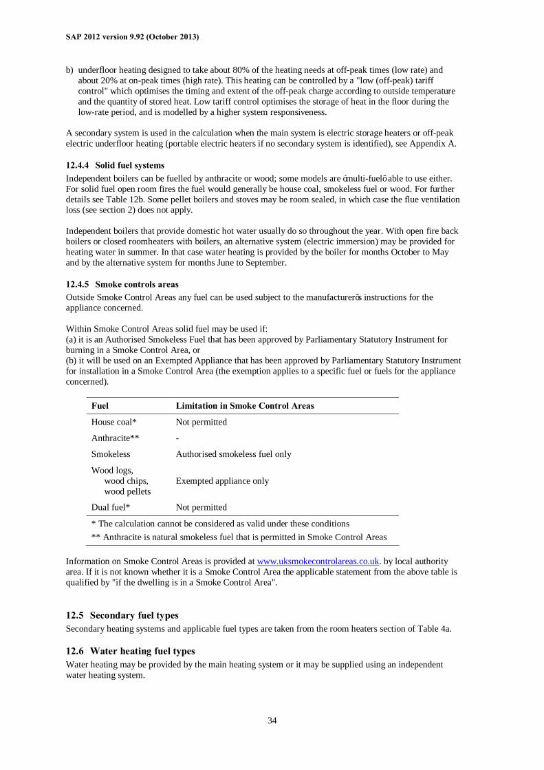
SAP 2012 version 9.92 (October 2013)
34
b) underfloor heating designed to take about 80% of the heating needs at off-peak times (low rate) and about 20% at on-peak times (high rate). This heating can be controlled by a "low (off-peak) tariff control" which optimises the timing and extent of the off-peak charge according to outside temperature and the quantity of stored heat. Low tariff control optimises the storage of heat in the floor during the low-rate period, and is modelled by a higher system responsiveness.
A secondary system is used in the calculation when the main system is electric storage heaters or off-peak electric underfloor heating (portable electric heaters if no secondary system is identified), see Appendix A.
12.4.4 Solid fuel systems Independent boilers can be fuelled by anthracite or wood; some models are ‘multi-fuel’ able to use either. For solid fuel open room fires the fuel would generally be house coal, smokeless fuel or wood. For further details see Table 12b. Some pellet boilers and stoves may be room sealed, in which case the flue ventilation loss (see section 2) does not apply. Independent boilers that provide domestic hot water usually do so throughout the year. With open fire back boilers or closed roomheaters with boilers, an alternative system (electric immersion) may be provided for heating water in summer. In that case water heating is provided by the boiler for months October to May and by the alternative system for months June to September.
12.4.5 Smoke controls areas Outside Smoke Control Areas any fuel can be used subject to the manufacturer’s instructions for the appliance concerned. Within Smoke Control Areas solid fuel may be used if: (a) it is an Authorised Smokeless Fuel that has been approved by Parliamentary Statutory Instrument for burning in a Smoke Control Area, or (b) it will be used on an Exempted Appliance that has been approved by Parliamentary Statutory Instrument for installation in a Smoke Control Area (the exemption applies to a specific fuel or fuels for the appliance concerned).
Fuel Limitation in Smoke Control Areas
House coal* Not permitted
Anthracite** -
Smokeless Authorised smokeless fuel only
Wood logs, wood chips, wood pellets
Exempted appliance only
Dual fuel* Not permitted
* The calculation cannot be considered as valid under these conditions ** Anthracite is natural smokeless fuel that is permitted in Smoke Control Areas
Information on Smoke Control Areas is provided at www.uksmokecontrolareas.co.uk. by local authority area. If it is not known whether it is a Smoke Control Area the applicable statement from the above table is qualified by "if the dwelling is in a Smoke Control Area".
12.5 Secondary fuel types Secondary heating systems and applicable fuel types are taken from the room heaters section of Table 4a.
12.6 Water heating fuel types Water heating may be provided by the main heating system or it may be supplied using an independent water heating system.
SAP 2012 version 9.92 (October 2013)
35
Whenever water heating is supplied by a system using off-peak electricity it is assumed that a proportion of the water heating will, nevertheless, take place at on-peak times (and so be charged at the high rate). This proportion is calculated using Table 13 and the percentage is dependent on the total floor area and the cylinder size. This table should be linearly interpolated (in both directions where necessary) for intermediate values. The limits of cylinder size in the table are cut-off points, so that if, for instance, the cylinder size used is 105 litres, the values for 110 litres should be used instead.
12.7 Electricity for pumps and fans An allowance for the electricity used has to be made for systems that include any of the following:
• central heating pump; • boiler with fan assisted flue; • warm air heating system fans; • whole house mechanical ventilation; • keep-hot facility (electric) for gas combi boilers
Where there is an off-peak tariff the proportions of electricity at the high and low rates are given in Table 12a. Note that the allowance in this section for fan-assisted flues only applies for a main heating system – fan-assisted flues for secondary heaters should not be counted. Data are given in Table 4f.
12.8 Electricity for lighting The electricity used for lighting is calculated according to the procedure in Appendix L. The calculation allows for low-energy lighting provided by fixed outlets (both dedicated fittings and compact fluorescent lamps) on the basis of the proportion of the fixed outlets that have low-energy fittings.
13 ENERGY COST RATING The SAP rating is related to the total energy cost by the equations: ECF = deflator × total cost / (TFA + 45) (9) if ECF ≥ 3.5, SAP 2012 = 117 – 121 × log10(ECF) (10) if ECF < 3.5, SAP 2012 = 100 – 13.95 × ECF (11) where the total cost is calculated at (255) or (355) and TFA is the total floor area of the dwelling at (4). The SAP rating takes into account energy for lighting, and also energy generated in the dwelling using technologies like micro-CHP or photovoltaics. The SAP rating scale has been set so that SAP 100 is achieved at zero-ECF. It can rise above 100 if the dwelling is a net exporter of energy. The SAP rating is essentially independent of floor area. The SAP rating is rounded to the nearest integer. If the result of the calculation is less than 1 the rating should be quoted as 1. Energy efficiency rating bands are defined by the SAP rating according to Table 14.
14 CARBON DIOXIDE EMISSIONS AND PRIMARY ENERGY CO2 emissions attributable to a dwelling are those for space and water heating, ventilation and lighting, less the emissions saved by energy generation technologies. The calculation should proceed by following the appropriate section of the SAP worksheet, designed for calculating carbon dioxide emissions for: a) individual heating systems and community heating without combined heat and power (CHP); or b) community heating with CHP or utilising waste heat from power stations. The Environmental Impact Rating (EI rating) is related to the annual CO2 emissions by:
SAP 2012 version 9.92 (October 2013)
36
CF = (CO2 emissions) / (TFA + 45) (12) if CF >= 28.3 EI rating = 200 – 95 × log10(CF) (13) if CF < 28.3 EI rating = 100 – 1.34 × CF (14) where the CO2 emissions are calculated at (272) or (383) and TFA is the total floor area of the dwelling at (4). The EI rating scale has been set so that EI 100 is achieved at zero net emissions. It can rise above 100 if the dwelling is a net exporter of energy. The EI rating is essentially independent of floor area. The EI rating is rounded to the nearest integer. If the result of the calculation is less than 1 the rating should be quoted as 1. Environmental impact rating bands are defined by the EI rating according to Table 14. Primary energy is calculated in the same way as CO2 emission using the primary energy factors in Table 12 in place of the CO2 emission factors.
15 BUILDING REGULATIONS AND DWELLING EMISSIONS RATE (DER) Building regulations may refer to CO2 emissions as calculated by the SAP as a method of demonstrating compliance with regulations for the conservation of fuel and power and/or limitation of energy use. The current requirements of regulations can be checked against documents available at: England www.communities.gov.uk Wales http://wales.gov.uk/topics/planning/buildingregs/?lang=en Scotland www.scotland.gov.uk/bsd Northern Ireland www.buildingregulationsni.gov.uk As at the date of this document, building regulations in all four jurisdictions mentioned above place limitations on the permissible annual CO2 emissions from new dwellings, expressed in kilograms per square metre of floor area (kg/m²). This quantity, when calculated taking account of specific requirements in the applicable regulatory document and expressed in kilograms per unit floor area to two decimal places, is known as the Dwelling Emissions Rate, or DER. The applicable regulatory document may impose specific conditions for the calculation of the DER (such as the version of SAP to be used), which must be followed for DER calculations. Appendix R gives reference values to define a notional dwelling, which may be referred to in building regulations in connection with establishing a target fabric energy efficiency and/or a target CO2 emissions rate.
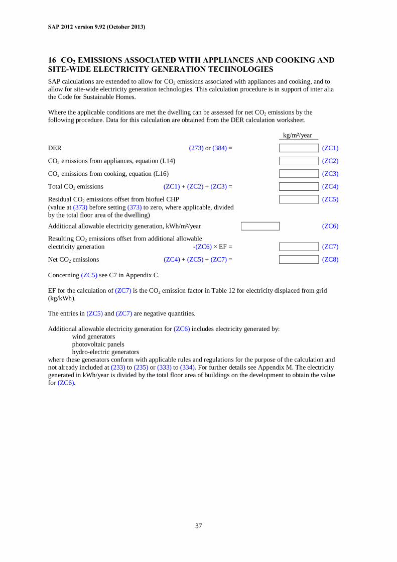
SAP 2012 version 9.92 (October 2013)
37
16 CO2 EMISSIONS ASSOCIATED WITH APPLIANCES AND COOKING AND SITE-WIDE ELECTRICITY GENERATION TECHNOLOGIES SAP calculations are extended to allow for CO2 emissions associated with appliances and cooking, and to allow for site-wide electricity generation technologies. This calculation procedure is in support of inter alia the Code for Sustainable Homes. Where the applicable conditions are met the dwelling can be assessed for net CO2 emissions by the following procedure. Data for this calculation are obtained from the DER calculation worksheet. kg/m²/year DER (273) or (384) = (ZC1) CO2 emissions from appliances, equation (L14) (ZC2) CO2 emissions from cooking, equation (L16) (ZC3) Total CO2 emissions (ZC1) + (ZC2) + (ZC3) = (ZC4) Residual CO2 emissions offset from biofuel CHP (ZC5) (value at (373) before setting (373) to zero, where applicable, divided by the total floor area of the dwelling)
Additional allowable electricity generation, kWh/m²/year (ZC6) Resulting CO2 emissions offset from additional allowable electricity generation -(ZC6) × EF = (ZC7) Net CO2 emissions (ZC4) + (ZC5) + (ZC7) = (ZC8) Concerning (ZC5) see C7 in Appendix C. EF for the calculation of (ZC7) is the CO2 emission factor in Table 12 for electricity displaced from grid (kg/kWh). The entries in (ZC5) and (ZC7) are negative quantities. Additional allowable electricity generation for (ZC6) includes electricity generated by: wind generators photovoltaic panels hydro-electric generators where these generators conform with applicable rules and regulations for the purpose of the calculation and not already included at (233) to (235) or (333) to (334). For further details see Appendix M. The electricity generated in kWh/year is divided by the total floor area of buildings on the development to obtain the value for (ZC6).
SAP 2012 version 9.92 (October 2013)
38
References 1. Anderson B R, A J Clark, R Baldwin and N O Milbank, BREDEM The BRE Domestic Energy
Model: background, philosophy and description. BRE Report: BR 66, BRE, Garston, 1985 2. Henderson G and L D Shorrock, BREDEM - BRE Domestic Energy Model - testing the predictions of
a two zone model, Build. Serv. Eng. Res. Technol., 7(2) 1986, pp87-91 3. Shorrock L D,, Macmillan S, Clark J and Moore G,.BREDEM-8, a Monthly Calculation Method for
Energy Use in Dwellings: Testing and Development, Proceedings of Building Environmental Performance ’91, BEPAC 1991
4. Shorrock L D, Dunster J E, Seale C F, Eppel H and Lomas K J, Testing BREDEM-8 Against
Measured Consumption Data and Against Simulation Models, Proceedings of Building Environmental Performance ’94, BEPAC 1994
5. Shorrock L D and Anderson B R, A guide to the development of BREDEM. BRE Information Paper
IP 4/95, BRE, Garston, 1995. 6. Dickson C M, Dunster J E, Lafferty S Z and Shorrock L D, BREDEM: Testing monthly and
seasonal versions against measurements and against detailed simulation models, Build. Serv. Eng. Res. Technol, 17(3), 1996
7. Anderson B R, Chapman PF, Cutland N G, Dickson C M, Henderson G, Henderson J H, Iles P J,
Kosmina L and Shorrock L D. BREDEM-12 Model description – 2001 update. BRE, Garston, 2002
8. Anderson B R, Energy assessment for dwellings using BREDEM worksheets, BRE Information Paper
IP 13/88, BRE, Garston, 1988 9. CIBSE Guide A3, The Chartered Institution of Building Services Engineers, CIBSE, London, 2006 BRE documents are available from: IHS BRE Press Willoughby Road Bracknell Berkshire RG12 8FB Tel 01344 328038 Fax 01344 328005 www.brebookshop.com
List of standards referred to in this document Reference Title Content BS EN ISO 6946
Building components and building elements – Thermal resistance and thermal transmittance – Calculation method
Calculation of U-values for walls and roofs.
BS EN ISO 13789
Thermal performance of buildings – transmission and ventilation heat transfer coefficients – Calculation method
Heat loss rate from whole building
SAP 2012 version 9.92 (October 2013)
39
Reference Title Content BS EN ISO 10456
Building materials and products – Hygrothermal properties – Tabulated design values and procedures for determining declared and design thermal values
Lists of thermal data for materials
BS EN ISO 10077-1
Thermal performance of windows, doors and shutters – Calculation of thermal transmittance – Part 1: General
U-values for windows and doors
BS EN ISO 10077-2
Thermal performance of windows, doors and shutters – Calculation of thermal transmittance – Part 2: Numerical method for frames
U-values for window frames
BS EN ISO 12567
Thermal performance of windows and doors – Determination of thermal transmittance by hot box method
U-value measurement for windows and doors
BS EN ISO 13370
Thermal performance of buildings – Heat transfer via the ground – Calculation methods
U-values for floors
BS EN ISO 13790
Energy performance of buildings – Calculation of energy use for space heating and cooling
Energy calculations
BS EN 13203-2
Gas-fired domestic appliances producing hot water – Appliances not exceeding 70 kW heat input and 300 l water storage capacity – Part 2: Assessment of energy consumption
Efficiency of gas combi boilers for DHW heating.
OFTEC Oil Firing Product Standard OPS 26
Guidance for the use of BS EN 13203-2:2006 for liquid fuel fired combination boilers up to 70 kW rated input and with up to 100 litres hot water storage capacity
Efficiency of oil combi boilers for DHW heating.
BS EN 16147
Heat pumps with electrically driven compressors – Testing and requirements for marking of domestic hot water units
Efficiency of heat pumps for DHW heating
BS EN 60531
Household electric thermal storage room heaters – Methods for measuring performance
Characteristics of storage heaters
BS 7977-1
Specification for safety and rational use of energy of domestic gas appliances – Part 1: Radiant/convectors
Gas fires
British Standards are available from:
BSI Chiswick High Road London W4 4AL Tel: 020 8996 9001 Fax: 020 8996 7001 www.bsigroup.com
SAP 2012 version 9.92 (October 2013)
40
Appendix A: Main and secondary heating systems
A1 General principles The main heating system is that which heats the largest proportion of dwelling. It is a heating system which is not usually based on individual room heaters (although it can be), and often provides hot water as well as space heating. Main heating systems are either identified via the Product Characteristics Database or are categorised on the basis of the generic types in Tables 4a and 4b. Occasionally there may be two main heating systems, for example two separate boilers used to heat different parts of the property or a system that utilises more than one heat-raising technology. The total space heating requirement (98) is divided between the two systems in proportion to the amount of heat provided by each system. Where the two systems heat separate parts of the property, unless specified otherwise for particular systems, the proportion of heat provided by each system should be taken as the relative heated floor area served by each system. The calculation of the space heating requirement uses the characteristics (responsiveness and control type) weighted for the two systems (see Tables 9b and 9c). Separate efficiencies, costs and emission factors are then applied for each system. The following restrictions apply:
- system 1 always heats the living area; - community heating, micro-CHP and heat pumps from the database can be only main system 1, except
that a heat pump from the database providing DHW only can be assigned to main system 2 with a space heating fraction of zero;
- if system 1 is community heating there is no system 2. The secondary heating system is based upon a room heater. Secondary heating systems are taken from the room heaters section of Table 4a. Only fixed secondary heaters are included in a description of the property (e.g. a gas fire, a chimney and hearth capable of supporting an open fire, a wall-mounted electric fire). Except as mentioned in the next paragraph, portable heaters are not counted for the purposes of SAP assessments: these are characterised by being:
- completely free standing and self supporting on feet, legs or base on the floor, i.e. not wall mounted or specifically designed for a fireplace, and in the case of gas or oil heaters containing a built-in fuel store; and
- readily and easily transferred and relocated from one room to another, in the case of an electric heater having a lead and a plug.
A secondary system is always included for the SAP calculation when the main system (or main system 1 when there are two systems) is electric storage heaters or off-peak electric underfloor heating. This applies to main heating codes 401 to 407, 409 and 421. Portable electric heaters (693) are used in the calculation if no secondary system has been identified. SAP software inserts portable electric heaters for the calculation in such cases. For detailed selection rules for main and secondary systems see A2 below. If a fixed secondary heater is not present, a secondary heating system is nevertheless used for the calculation of the energy use and energy ratings where the main system is not sufficient in itself to heat all habitable rooms in the dwelling to the level on which the SAP is based (21°C in the living area and 18°C elsewhere). This should be taken as applicable if there are any habitable rooms without heat emitters associated with the main heating system. See section A4 as regards the calculation routine. Note that building regulations or other regulations may make additional specifications in relation to secondary heaters, which should be followed in the case of compliance calculations. The SAP calculation is based on the characteristics of the dwelling and the systems installed and not on the heating practices of the occupying household. That does not preclude further estimates of energy consumption being made to take account of actual usage. Such estimates are not part of SAP but could form
SAP 2012 version 9.92 (October 2013)
41
the basis of advice given to the occupying household on how to make best use of the systems at their disposal.
A2 Procedure for identifying main and secondary heating systems
A2.1 Identifying the main system (1) If there is a central system that provides both space and water heating and it is capable of heating at
least 30% of the dwelling, select that system as the main heating system. If there is no system that provides both space and water heating, then select the system that has the capability of heating the greatest part of the dwelling. For this purpose only habitable rooms should be considered (i.e. ignore heaters in non-habitable rooms).
(2) If there is still doubt about which system should be selected as the main system, select the system that
supplies useful heat to the dwelling at lowest cost (obtained by dividing fuel cost by conversion efficiency).
A2.2 Identifying the secondary system (1) Count the number of habitable rooms and the number heated habitable rooms (for the definition of
habitable rooms see S9.1 in Appendix S). (2) If a fixed secondary heater is found in a habitable room, that heater is the secondary, whether or not
there are any unheated habitable rooms. (3) If there is an unheated habitable room and no fixed secondary heater in any habitable room, but there is
a fixed heater in a non-habitable room, that heater is the secondary. (4) If no heater is identified in (2) or (3) there is no fixed secondary heater. In some cases it may not be immediately clear which of two systems present should be classified as the main system and which as the secondary. In these cases the system which is cheapest to use should be taken as the main system, and if there is still doubt, i.e. if they are both equally cheap to use, select the system that heats the living room. The other system can still be input as a secondary system but it needs to be input as a room heater. A room heater system should be chosen so that its efficiency closely reflects (but does not exceed) that of the actual system (as defined by Table 4a). The chosen room heater should also use the same fuel/tariff as the actual system. If two types of secondary heater are present, that which heats the greater number of rooms should be specified as the secondary system. If that condition does not resolve the choice, the system with the lowest efficiency should be specified.
A3 Dwellings with inadequate heating systems
A3.1 New dwellings The SAP assumes that a good standard of heating will be achieved throughout the dwelling. For dwellings in which the heating system is not capable of providing the standard, it should be assumed that the additional heating is provided by electric heaters, using the fraction given in Table 11 (but see also A3.3). For new dwellings that have no heating system specified, it should be assumed that all heat will be provided by electric heaters using electricity at the standard domestic tariff.
A3.2 Existing dwellings Some existing dwellings have heaters only in a limited number of rooms, generally gas or electric fires. In these cases the usual basis of calculation, that the dwelling is fully heated, still applies. Rooms without heaters are assumed to be heated by electric room heaters. The choice between main and secondary heating for the purposes of the calculation is decided as follows.
SAP 2012 version 9.92 (October 2013)
42
(1) If 25% or less of the habitable rooms are actually heated, and are heated by room heater(s) using a fuel other than electricity, the (assumed) electric system is the main system (or main system 1 when there are two) for the purposes of the calculation and the other fuel is the secondary. This applies only if the identified main heater is a room heater and there is no identified secondary heater, and is subject to A3.3 below. If water heating is from the main system (e.g. the room heater has a back boiler) the water heating becomes from the secondary system for the calculation. A heated room means one with a heat emitter in the room.
(2) If the number of habitable rooms actually heated is more than 25% but there is no identified secondary
heater according to the rules in A2.2, the heaters in these rooms are the main system and the (assumed) electric heaters are the secondary.
(3) If the number of habitable rooms actually heated is more than 25% and a secondary heater is identified,
the procedure for assigning main and secondary heating systems outlined in section A2 applies. Examples. A house with 6 habitable rooms with one gas fire would be treated as being electrically heated with a gas secondary heater (1 room out of 6). If there were two gas fires (2 rooms out of 6), the gas fires are the main heating and electricity the secondary. If there were 4 habitable rooms, and one gas fire (1 out of 4), the main heating would be electric and the gas fire the secondary.
A3.3 Highly insulated small dwellings In the case of highly insulated small dwellings, item (1) in A3.2 may not be realistic, for example a 3 kW gas fire could suffice to provide most of the heating needs. Accordingly, if the design heat loss (DHL) is less than 3 kW, the heating in the main room is the main system irrespective of the number of rooms heated. For this purpose, DHL is the annual average heat loss coefficient as calculated at worksheet (37), multiplied by a design temperature difference of 20 K. Note. When considering improvement measures, this condition is tested only for the existing dwelling.
A3.4 Broken heating systems or no heating system SAP assumes that the installed heating systems are operational and takes no account of whether they are working or not. However, in the case where the main heating unit (e.g. boiler) is missing and thus the dwelling has no installed main heating system, or if there is no heating system present at all, the calculation should be done for main heating as direct electric heaters in all rooms (no secondary heaters).
A4 Description of the dwelling’s heating systems and software implementation A SAP assessor should record, for the purposes of entry into SAP calculation software, the actual heating systems (as found in the dwelling in the case of a site survey or indicated on building plans or associated documentation in the case of new construction), together with the number of habitable rooms and the number of heated habitable rooms. Where case A3.2 (1) applies, the description of the property includes the actual main system. Where a choice has to be made between alternative systems, as described in Section A2, the SAP assessor should make the choice according to the circumstances existing in the property while recording in a separate note any other fixed heaters present. Software implementing the SAP calculation procedure then applies the remaining rules of this Appendix, namely: a) If there is no heating system, assign electric heaters as the main system heating all rooms (no secondary
system). b) If 25% or less of the habitable rooms are heated and their heating is by a room heater (not electric),
assign electric heaters as the main system and the identified room heaters as the secondary system, applying the secondary fraction according to Table 11 for electric room heaters as the main system. (This is not done when the condition in A3.3 applies.)
If two main heating systems have been identified (e.g. a gas fire in one room, a coal fire in another
room, plus 6 unheated habitable rooms) then: - assign electric heaters as main system 1 - assign the room heater entered as main system 1 as the secondary system - main system 2 remains as it is

SAP 2012 version 9.92 (October 2013)
43
- set the fraction of heat from main system 2 equal to heated habitable rooms divided by total habitable rooms
c) Otherwise if there are any unheated habitable rooms and no secondary system has been identified,
undertake the calculation with electric secondary heating (portable electric heaters). d) If any fixed secondary heater has been identified, the calculation proceeds with the identified secondary
heater, whether or not there are unheated habitable rooms. e) If there are no unheated habitable rooms and no fixed secondary heater in a habitable room, undertake
the calculation with no secondary heating. f) An assumed heater, where main or secondary, is an electric portable heater. In case of main heating it
does not have thermostatic control. Table 11 gives the fraction of the heating that is assumed to be supplied by the secondary system. The treatment of secondary systems is not affected by any control options for the secondary system.
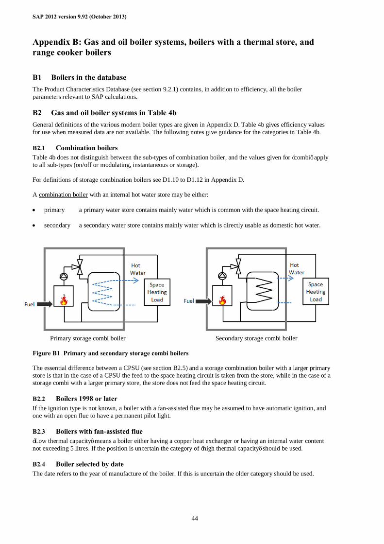
SAP 2012 version 9.92 (October 2013)
44
Appendix B: Gas and oil boiler systems, boilers with a thermal store, and range cooker boilers
B1 Boilers in the database The Product Characteristics Database (see section 9.2.1) contains, in addition to efficiency, all the boiler parameters relevant to SAP calculations.
B2 Gas and oil boiler systems in Table 4b General definitions of the various modern boiler types are given in Appendix D. Table 4b gives efficiency values for use when measured data are not available. The following notes give guidance for the categories in Table 4b.
B2.1 Combination boilers Table 4b does not distinguish between the sub-types of combination boiler, and the values given for ‘combi’ apply to all sub-types (on/off or modulating, instantaneous or storage). For definitions of storage combination boilers see D1.10 to D1.12 in Appendix D. A combination boiler with an internal hot water store may be either: • primary a primary water store contains mainly water which is common with the space heating circuit. • secondary a secondary water store contains mainly water which is directly usable as domestic hot water.
Primary storage combi boiler Secondary storage combi boiler Figure B1 Primary and secondary storage combi boilers The essential difference between a CPSU (see section B2.5) and a storage combination boiler with a larger primary store is that in the case of a CPSU the feed to the space heating circuit is taken from the store, while in the case of a storage combi with a larger primary store, the store does not feed the space heating circuit.
B2.2 Boilers 1998 or later If the ignition type is not known, a boiler with a fan-assisted flue may be assumed to have automatic ignition, and one with an open flue to have a permanent pilot light.
B2.3 Boilers with fan-assisted flue ‘Low thermal capacity’ means a boiler either having a copper heat exchanger or having an internal water content not exceeding 5 litres. If the position is uncertain the category of ‘high thermal capacity’ should be used.
B2.4 Boiler selected by date The date refers to the year of manufacture of the boiler. If this is uncertain the older category should be used.
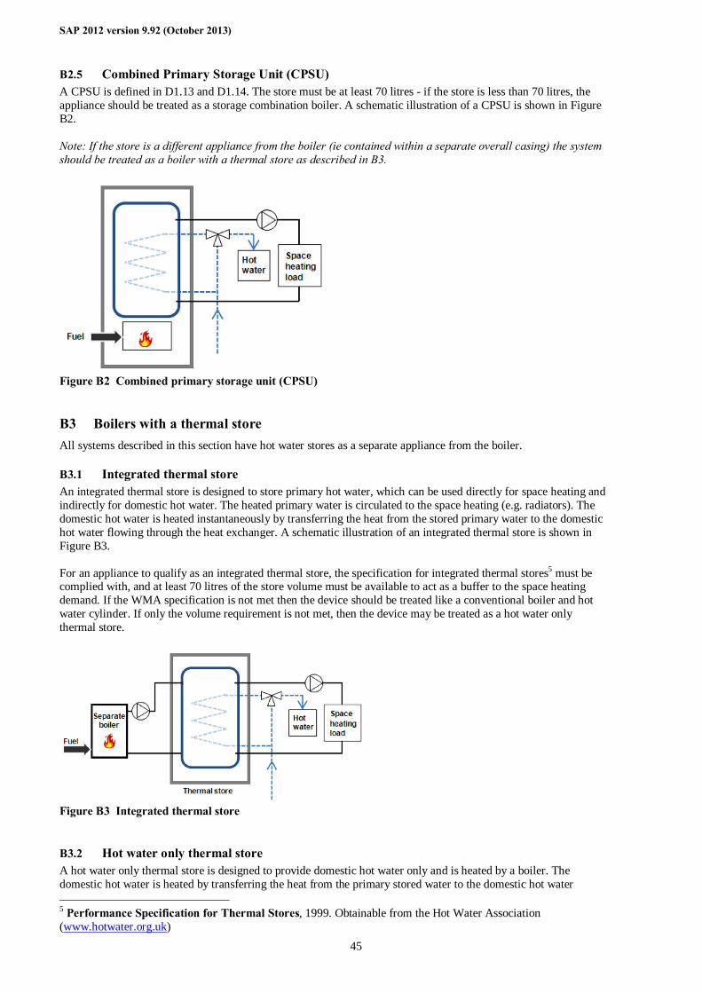
SAP 2012 version 9.92 (October 2013)
45
B2.5 Combined Primary Storage Unit (CPSU) A CPSU is defined in D1.13 and D1.14. The store must be at least 70 litres - if the store is less than 70 litres, the appliance should be treated as a storage combination boiler. A schematic illustration of a CPSU is shown in Figure B2. Note: If the store is a different appliance from the boiler (ie contained within a separate overall casing) the system should be treated as a boiler with a thermal store as described in B3.
Figure B2 Combined primary storage unit (CPSU)
B3 Boilers with a thermal store All systems described in this section have hot water stores as a separate appliance from the boiler.
B3.1 Integrated thermal store An integrated thermal store is designed to store primary hot water, which can be used directly for space heating and indirectly for domestic hot water. The heated primary water is circulated to the space heating (e.g. radiators). The domestic hot water is heated instantaneously by transferring the heat from the stored primary water to the domestic hot water flowing through the heat exchanger. A schematic illustration of an integrated thermal store is shown in Figure B3. For an appliance to qualify as an integrated thermal store, the specification for integrated thermal stores5 must be complied with, and at least 70 litres of the store volume must be available to act as a buffer to the space heating demand. If the WMA specification is not met then the device should be treated like a conventional boiler and hot water cylinder. If only the volume requirement is not met, then the device may be treated as a hot water only thermal store.
Figure B3 Integrated thermal store
B3.2 Hot water only thermal store A hot water only thermal store is designed to provide domestic hot water only and is heated by a boiler. The domestic hot water is heated by transferring the heat from the primary stored water to the domestic hot water 5 Performance Specification for Thermal Stores, 1999. Obtainable from the Hot Water Association (www.hotwater.org.uk)
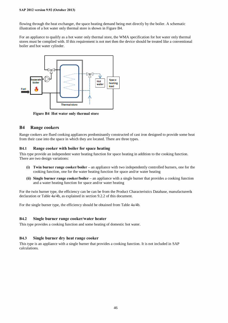
SAP 2012 version 9.92 (October 2013)
46
flowing through the heat exchanger, the space heating demand being met directly by the boiler. A schematic illustration of a hot water only thermal store is shown in Figure B4. For an appliance to qualify as a hot water only thermal store, the WMA specification for hot water only thermal stores must be complied with. If this requirement is not met then the device should be treated like a conventional boiler and hot water cylinder.
Figure B4 Hot water only thermal store
B4 Range cookers Range cookers are flued cooking appliances predominantly constructed of cast iron designed to provide some heat from their case into the space in which they are located. There are three types.
B4.1 Range cooker with boiler for space heating This type provide an independent water heating function for space heating in addition to the cooking function. There are two design variations:
(i) Twin burner range cooker/boiler – an appliance with two independently controlled burners, one for the cooking function, one for the water heating function for space and/or water heating
(ii) Single burner range cooker/boiler – an appliance with a single burner that provides a cooking function and a water heating function for space and/or water heating
For the twin burner type, the efficiency can be can be from the Product Characteristics Database, manufacturer’s declaration or Table 4a/4b, as explained in section 9.2.2 of this document. For the single burner type, the efficiency should be obtained from Table 4a/4b.
B4.2 Single burner range cooker/water heater This type provides a cooking function and some heating of domestic hot water.
B4.3 Single burner dry heat range cooker This type is an appliance with a single burner that provides a cooking function. It is not included in SAP calculations.
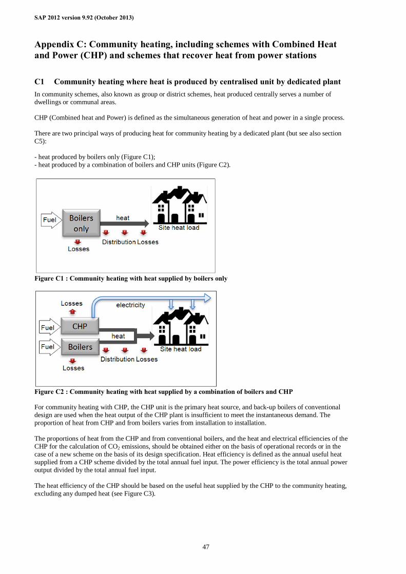
SAP 2012 version 9.92 (October 2013)
47
Appendix C: Community heating, including schemes with Combined Heat and Power (CHP) and schemes that recover heat from power stations
C1 Community heating where heat is produced by centralised unit by dedicated plant In community schemes, also known as group or district schemes, heat produced centrally serves a number of dwellings or communal areas. CHP (Combined heat and Power) is defined as the simultaneous generation of heat and power in a single process. There are two principal ways of producing heat for community heating by a dedicated plant (but see also section C5): - heat produced by boilers only (Figure C1); - heat produced by a combination of boilers and CHP units (Figure C2).
Figure C1 : Community heating with heat supplied by boilers only
Figure C2 : Community heating with heat supplied by a combination of boilers and CHP For community heating with CHP, the CHP unit is the primary heat source, and back-up boilers of conventional design are used when the heat output of the CHP plant is insufficient to meet the instantaneous demand. The proportion of heat from CHP and from boilers varies from installation to installation. The proportions of heat from the CHP and from conventional boilers, and the heat and electrical efficiencies of the CHP for the calculation of CO2 emissions, should be obtained either on the basis of operational records or in the case of a new scheme on the basis of its design specification. Heat efficiency is defined as the annual useful heat supplied from a CHP scheme divided by the total annual fuel input. The power efficiency is the total annual power output divided by the total annual fuel input. The heat efficiency of the CHP should be based on the useful heat supplied by the CHP to the community heating, excluding any dumped heat (see Figure C3).
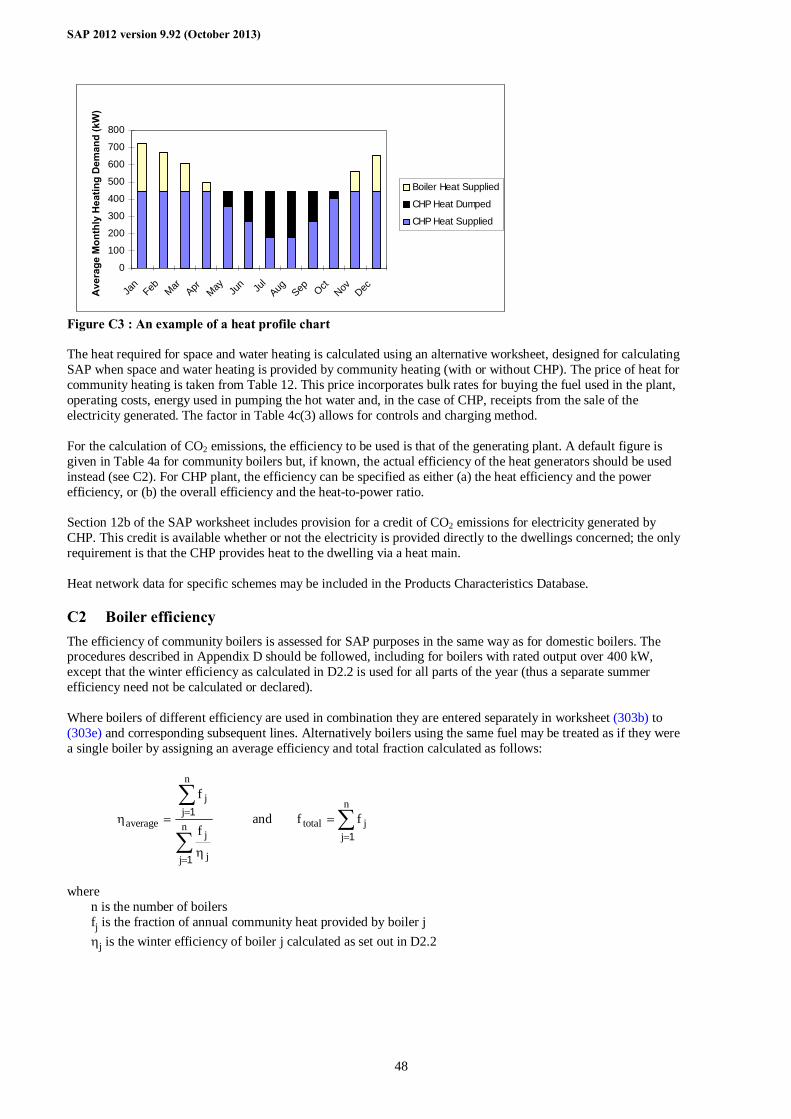
SAP 2012 version 9.92 (October 2013)
48
Figure C3 : An example of a heat profile chart The heat required for space and water heating is calculated using an alternative worksheet, designed for calculating SAP when space and water heating is provided by community heating (with or without CHP). The price of heat for community heating is taken from Table 12. This price incorporates bulk rates for buying the fuel used in the plant, operating costs, energy used in pumping the hot water and, in the case of CHP, receipts from the sale of the electricity generated. The factor in Table 4c(3) allows for controls and charging method. For the calculation of CO2 emissions, the efficiency to be used is that of the generating plant. A default figure is given in Table 4a for community boilers but, if known, the actual efficiency of the heat generators should be used instead (see C2). For CHP plant, the efficiency can be specified as either (a) the heat efficiency and the power efficiency, or (b) the overall efficiency and the heat-to-power ratio. Section 12b of the SAP worksheet includes provision for a credit of CO2 emissions for electricity generated by CHP. This credit is available whether or not the electricity is provided directly to the dwellings concerned; the only requirement is that the CHP provides heat to the dwelling via a heat main. Heat network data for specific schemes may be included in the Products Characteristics Database.
C2 Boiler efficiency The efficiency of community boilers is assessed for SAP purposes in the same way as for domestic boilers. The procedures described in Appendix D should be followed, including for boilers with rated output over 400 kW, except that the winter efficiency as calculated in D2.2 is used for all parts of the year (thus a separate summer efficiency need not be calculated or declared). Where boilers of different efficiency are used in combination they are entered separately in worksheet (303b) to (303e) and corresponding subsequent lines. Alternatively boilers using the same fuel may be treated as if they were a single boiler by assigning an average efficiency and total fraction calculated as follows:
∑
∑
=
=
η
=ηn
j j
j
n
jj
average f
f
1
1 and ∑=
=n
jjtotal ff
1
where
n is the number of boilers fj is the fraction of annual community heat provided by boiler j ηj is the winter efficiency of boiler j calculated as set out in D2.2
0
100
200
300
400
500
600
700
800
Jan
Feb Mar Apr May Jun Ju
lAug Sep Oct
Nov DecAve
rage
Mon
thly
Hea
ting
Dem
and
(kW
)
Boiler Heat Supplied
CHP Heat Dumped
CHP Heat Supplied
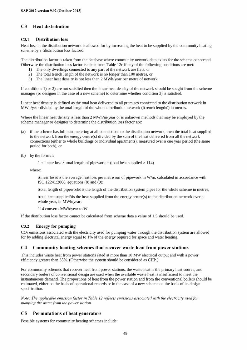
SAP 2012 version 9.92 (October 2013)
49
C3 Heat distribution
C3.1 Distribution loss Heat loss in the distribution network is allowed for by increasing the heat to be supplied by the community heating scheme by a ‘distribution loss factor’. The distribution factor is taken from the database where community network data exists for the scheme concerned. Otherwise the distribution loss factor is taken from Table 12c if any of the following conditions are met:
1) The only dwellings connected to any part of the network are flats, or 2) The total trench length of the network is no longer than 100 metres, or 3) The linear heat density is not less than 2 MWh/year per metre of network.
If conditions 1) or 2) are not satisfied then the linear heat density of the network should be sought from the scheme manager (or designer in the case of a new scheme) to determine whether condition 3) is satisfied. Linear heat density is defined as the total heat delivered to all premises connected to the distribution network in MWh/year divided by the total length of the whole distribution network (“trench length”) in metres. Where the linear heat density is less than 2 MWh/m/year or is unknown methods that may be employed by the scheme manager or designer to determine the distribution loss factor are: (a) if the scheme has full heat metering at all connections to the distribution network, then the total heat supplied
to the network from the energy centre(s) divided by the sum of the heat delivered from all the network connections (either to whole buildings or individual apartments), measured over a one year period (the same period for both), or
(b) by the formula
1 + linear loss × total length of pipework ÷ (total heat supplied × 114)
where:
‘linear loss’ is the average heat loss per metre run of pipework in W/m, calculated in accordance with ISO 12241:2008, equations (8) and (9);
‘total length of pipework’ is the length of the distribution system pipes for the whole scheme in metres;
‘total heat supplied’ is the heat supplied from the energy centre(s) to the distribution network over a whole year, in MWh/year;
114 converts MWh/year to W.
If the distribution loss factor cannot be calculated from scheme data a value of 1.5 should be used.
C3.2 Energy for pumping CO2 emissions associated with the electricity used for pumping water through the distribution system are allowed for by adding electrical energy equal to 1% of the energy required for space and water heating.
C4 Community heating schemes that recover waste heat from power stations This includes waste heat from power stations rated at more than 10 MW electrical output and with a power efficiency greater than 35%. (Otherwise the system should be considered as CHP.) For community schemes that recover heat from power stations, the waste heat is the primary heat source, and secondary boilers of conventional design are used when the available waste heat is insufficient to meet the instantaneous demand. The proportions of heat from the power station and from the conventional boilers should be estimated, either on the basis of operational records or in the case of a new scheme on the basis of its design specification. Note: The applicable emission factor in Table 12 reflects emissions associated with the electricity used for pumping the water from the power station.
C5 Permutations of heat generators Possible systems for community heating schemes include:

SAP 2012 version 9.92 (October 2013)
50
1. A single boiler or set of boilers all using the same fuel. In the case of a set of boilers the average seasonal efficiency for the boilers is used for the calculation (see C2).
2. Two or more boilers or two or more sets of boilers, using different fuels such as mains gas and biomass. In this
case the total heat requirement is divided between the boilers or sets of boilers according to the design specification of the overall system. Different average seasonal efficiencies apply to the sets of boilers and the CO2 emissions are calculated using the emission factors of the respective fuels.
3. CHP plant and boiler(s), calculations according to section C1. If there are two or more boilers or two or more sets of boilers using different fuels (in addition to the CHP
plant) the heat requirement from boilers is divided between the boilers or sets of boilers according to the design specification of the overall system. Different average seasonal efficiencies apply to the sets of boilers and the CO2 emissions are calculated using the emission factors of the respective fuels.
4. Utilisation of waste heat from a power station topped up by boilers. 5. Geothermal heat topped up by boilers. 6. An electrically driven heat pump with various possibilities as to heat source, such as the ground or waste heat
from an industrial process. The calculation is essentially the same as that for boiler systems, with the seasonal performance factor (SPF) for the heat pump system being used in place of boiler efficiency. The SPF should take account of winter and summer operation as appropriate and of the temperature of the heat source.
C6 Community scheme providing DHW only Some community schemes provide DHW only, with the space heating provided by heaters in each dwelling. In this case the specification and calculation of space heating is the same as for a dwelling not connected to a community scheme. This includes a main heating system and secondary heaters. A DHW-only community scheme can be: - from community boilers; - from a community heat pump; - from a community CHP Data required are: - fuel used by community scheme (same fuel options as for community scheme providing space and water
heating) - efficiency of community boilers, heat pump or CHP - if CHP, the heat-to-power ratio - heat distribution characteristics for the distribution loss factor (Table 12c) - whether a hot water cylinder is in the dwelling and if so its volume plus either its measured loss factor or its
insulation type and insulation thickness. The water heating calculation follows that for a full community scheme including, if there is not a cylinder in the dwelling, assigning for the purposes of the calculation a 110 litre cylinder with a heat loss factor of 0.0152 kWh/litre/day. Allow for the control factor from Table 4c(3) and for the distribution loss factor from Table 12c. Include one-half of the normal community standing charge in the calculation of fuel costs unless the space heating is also a community system (see next paragraph). This also allows for the case where the community system is different for space heating and for water heating. Separate community heating parameters apply to each system including heat distribution characteristics. In this case the total standing charge is the normal community standing charge.
C7 Community biofuel CHP For community heating with CHP, it is possible for the total CO2 emissions calculated at (373) to be negative. Once this quantity becomes negative, it becomes advantageous to increase the heating requirements of the dwellings, e.g. by removing insulation. Accordingly (373) should be set to zero unless the dwellings served by the community scheme have a high standard of thermal insulation. That can be taken to be applicable in the case of new-build properties if the provisions for fabric insulation of the dwelling conform with the current requirements of building regulations.
SAP 2012 version 9.92 (October 2013)
51
Appendix D: Method of determining seasonal efficiency values for gas, oil and solid fuel boilers
This appendix sets out, in D2, D3 and D4, the method to be used by manufacturers to determine seasonal efficiency for particular gas and oil boilers when test data have been obtained to establish conformity with Council Directive 92/42/EEC6. This Directive has been implemented in the UK by the Boiler (Efficiency) Regulations7. EN 15502-1 and EN 15034 describe acceptable test procedures for gas and liquid fuel boilers respectively. Range cooker boilers with twin burners are covered by D5. Solid fuel boilers are covered by D7; an example of an acceptable procedure is EN 12809.
D1 Definitions Except for D1.1 these definitions apply only to boilers fuelled by gas or oil.
D1.1 Boiler A gas, liquid or solid fuelled appliance designed to provide hot water for space heating. It may (but need not) be designed to provide domestic hot water as well.
D1.2 Condensing boiler A boiler designed to make use of the latent heat released by the condensation of water vapour in the combustion flue products. The boiler must allow the condensate to leave the heat exchanger in liquid form by way of a condensate drain. ‘Condensing’ may only be applied to the definitions D1.3 to D1.14 inclusive. Boilers not so designed, or without the means to remove the condensate in liquid form, are called ‘non-condensing’.
D1.3 Regular boiler A boiler which does not have the capability to provide domestic hot water directly (i.e. not a combination boiler). It may nevertheless provide domestic hot water indirectly via a separate hot water storage cylinder.
D1.4 On/off regular boiler A regular boiler without the capability to vary the fuel burning rate whilst maintaining continuous burner firing. This includes those with alternative burning rates set once only at time of installation, referred to as range rating.
D1.5 Modulating regular boiler A regular boiler with the capability to vary the fuel burning rate whilst maintaining continuous burner firing.
D1.6 Combination boiler A boiler with the capability to provide domestic hot water directly, in some cases containing an internal hot water store.
D1.7 Instantaneous combination boiler A combination boiler without an internal hot water store, or with an internal hot water store of capacity less than 15 litres.
D1.8 On/off instantaneous combination boiler An instantaneous combination boiler that only has a single fuel burning rate for space heating. This includes appliances with alternative burning rates set once only at time of installation, referred to as range rating.
D1.9 Modulating instantaneous combination boiler An instantaneous combination boiler with the capability to vary the fuel burning rate whilst maintaining continuous burner firing.
6 Council Directive 92/42/EEC on efficiency requirements for new hot-water boilers fired with liquid or gaseous fuels. Official Journal of the European Communities No L/167/17. 21 May 1992, p. 92. 7 The Boiler (Efficiency) Regulations 1993, SI (1993) No 3083, as amended by the Boiler (Efficiency) (Amendment) Regulations 1994, SI (1994) No 3083.
SAP 2012 version 9.92 (October 2013)
52
D1.10 Storage combination boiler A combination boiler with an internal hot water store of capacity at least 15 litres but less than 70 litres OR a combination boiler with an internal hot water store of capacity at least 70 litres, in which the feed to the space heating circuit is not taken directly from the store. If the store is at least 70 litres and the feed to the space heating circuit is taken directly from the store, treat as a CPSU (D1.13 or D1.14).
D1.11 On/off storage combination boiler A storage combination boiler that only has a single fuel burning rate for space heating. This includes appliances with alternative burning rates set once only at time of installation, referred to as range rating.
D1.12 Modulating storage combination boiler A storage combination boiler with the capability to vary the fuel burning rate whilst maintaining continuous burner firing.
D1.13 On/off combined primary storage unit (CPSU) A single appliance designed to provide both space heating and the production of domestic hot water, in which there is a burner that heats a thermal store which contains mainly primary water which is in common with the space heating circuit. The store must have a capacity of at least 70 litres and the feed to the space heating circuit must be taken directly from the store. The appliance does not have the capability to vary the fuel burning rate whilst maintaining continuous burner firing. This includes those with alternative burning rates set once only at time of installation, referred to as range rating.
D1.14 Modulating combined primary storage unit (CPSU) A single appliance designed to provide both space heating and the production of domestic hot water, in which there is a burner that heats a thermal store which contains mainly primary water which is in common with the space heating circuit. The store must have a capacity of at least 70 litres and the feed to the space heating circuit must be taken directly from the store. The appliance has the capability to vary the fuel burning rate whilst maintaining continuous burner firing.
D1.15 Low temperature boiler A non-condensing boiler designed as a low temperature boiler and tested as a low temperature boiler as prescribed by the Boiler Efficiency Directive (i.e. the part load test was carried out at average boiler temperature of 40°C).
D1.16 Keep-hot facility A facility within an instantaneous combination boiler whereby water within the boiler may be kept hot while there is no demand. The water is kept hot either (i) solely by burning fuel, or (ii) by electricity, or (iii) both by burning fuel and by electricity, though not necessarily simultaneously.
D2 Method for calculating Seasonal Efficiencies for gas and oil boilers The method of calculation is applicable only to boilers for which the full load and the 30% part load efficiency values, obtained by the methods deemed to satisfy Council Directive 92/42/EEC, are available. These are net efficiency values. It is essential that both test results are available and that the tests are appropriate to the type of boiler as defined in the Council Directive, otherwise the calculation cannot proceed. Allowance has been made for the possibility that, in future, gross efficiency values will be supplied. The efficiencies calculated by this procedure are: a) SEDBUK (Seasonal Efficiency of Domestic Boilers in the UK). This is used as a general indicator of efficiency
for gas and oil boilers; it is no longer used for SAP calculations. b) Winter and summer seasonal efficiencies for SAP calculations. The winter seasonal efficiency is used for space
heating. The summer seasonal efficiency (ηsummer) applies to water heating in summer; the water heating efficiency in winter is derived from both.
c) The comparative hot water efficiency is a general indicator of efficiency for boilers; it is not used for SAP calculations.8
8 For combination boilers and CPSUs it is determined in accordance with EN 13203-2 tapping cycle 2 test results. For regular boilers or combination boilers and CPSUs not tested in accordance with that standard, an alternative procedure is provided.
SAP 2012 version 9.92 (October 2013)
53
In the calculation method the data are first converted (if necessary) to gross efficiency under test conditions, and then converted to a seasonal efficiency value that applies under typical conditions of use in a dwelling, allowing for standing losses. In this Appendix, efficiencies are expressed in percent. Intermediate calculations should be done to at least four places of decimals of a percentage, and the final result rounded to one decimal place.
D2.1 SEDBUK(2009) If the full-load efficiency and 30% part-load efficiency test results are available the procedure is as shown below. If they are not available see section D6 to convert a SEDBUK value that was calculated as specified in SAP 2005. 1. Determine fuel for boiler type The fuel for boiler type must be one of natural gas9, LPG (butane or propane), or oil (kerosene, gas oil or biodiesel). SEDBUK(2009) cannot be calculated for other fuels. 2. Obtain test data Retrieve the full-load efficiency and 30% part-load efficiency test results. Tests must have been carried out using the same fuel as the fuel for boiler type, except as provided in D4. 3. Convert net efficiencies to gross Establish whether the efficiency test results are gross or net (i.e. calculated on the basis of gross or net calorific value for the fuel used in the tests). If gross proceed to step 4. If net convert to gross using the following equation with the appropriate factor from Table D2.1.
ηgross = f × ηnet
Table D2.1 : Efficiency conversion factors
Fuel Net-to-gross conversion factor, f Natural gas 0.901 LPG (propane or butane) 0.921 Oil (kerosene or gas oil) 0.937 Oil (biodiesel) 0.937
4. Apply correction to high test results Apply an adjustment to full-load efficiency and to part-load efficiency to correct for observed bias in test results, according to Tables D2.2a and D2.2b.
Table D2.2a : Efficiency correction term for full-load tests
Fuel Full-load efficiency( ηFL) Threshold
value Correction if
ηFL > threshold Correction
if ηFL ≤ threshold
Natural Gas 86.0455 - 0.673 (ηFL – 86.0455) 0 LPG 87.9555 - 0.673 (ηFL – 87.9555) 0 Oil 89.4835 - 0.673 (ηFL – 89.4835) 0
Table D2.2b : Efficiency correction term for part-load tests
30% Part-load efficiency (ηPL)
Fuel Threshold value
Correction if ηPL > threshold
Correction if ηPL ≤
threshold Natural Gas 87.0366 - 0.213 (ηPL – 87.0366) 0
LPG 88.9686 - 0.213 (ηPL – 88.9686) 0 Oil 90.5142 - 0.213 (ηPL – 90.5142) 0
9 SEDBUK values derived from tests using natural gas are used for boilers fired by mains gas.
SAP 2012 version 9.92 (October 2013)
54
5. Reduce to maximum gross efficiency values Table D2.3 gives the maximum values of gross efficiency for each fuel that may be used. Reduce any greater value (after adjustment according to Table D2.2a or D2.2b) to the appropriate value given in Table D2.3.
Table D2.3 : Maximum gross efficiency values (in %)
Condensing boilers Non-condensing boilers Natural gas LPG Oil Natural gas LPG Oil Full-load 88.298 90.258 91.826 82.892 84.732 86.204 Part-load 97.308 97.626 97.448 88.991 83.811 87.141
6. Categorise the boiler a) Select the appropriate category for the boiler according to the definitions given in D1. b) If a gas or LPG boiler, determine whether it has a permanent pilot light: if it has a permanent pilot light, set p = 1 if not, set p = 0. c) In the case of a storage combination boiler (either on/off or modulating) determine from the test report whether
the losses from the store were included in the values reported (this depends on whether the store was connected to the boiler during the tests):
if the store loss is included, set b = 1 if not, set b = 0. d) In the case of a storage combination boiler or a CPSU, obtain the store volume, Vcs, in litres from the
specification of the device and the standby loss factor, L, using the following equation: if t < 10 mm: L = 0.0945 – 0.0055t if t ≥ 10 mm: L = 0.394/t where t is the thickness of the insulation of the store in mm. 7. Calculate seasonal efficiency a) Use the boiler category and other characteristics as defined in D1 (non-condensing or condensing; gas or LPG
or oil; on/off or modulating) to look up the appropriate SEDBUK equation number in Table D2.4. If no equation number is given the calculation cannot proceed. Otherwise, select the appropriate equation from Table D2.5 or Table D2.6.
b) Substitute the gross full and part load efficiencies (found in step 5) and p, b, V and L (found in step 6). Note
the result as ηannual for the purpose of D2.2. c) Round ηannual to one decimal place; i.e. to nearest 0.1%. The result may be described as SEDBUK(2009).
SAP 2012 version 9.92 (October 2013)
55
Table D2.4 : Boiler category table
non-condensing (see D1.2) condensing (see D1.2)
Gas or LPG Oil low-te
mpera
ture
(seeD
1.15)
Gas or LPG Oil
SEDBUK Equation numbers for different boiler types
on/o
ff
(see
D1.
4, D
1.8,
D1.
11, D
1.13
)
mod
ulat
ing
(see
D1.
5, D
1.9,
D1.
12, D
1.14
)
on/o
ff
(see
D1.
4, D
1.8,
D1.
11)
mod
ulat
ing
(see
D1.
5, D
1.9,
D1.
12)
on/o
ff
(see
D1.
4, D
1.8,
D1.
11, D
1.13
)
mod
ulat
ing
(see
D1.
5, D
1.9,
D1.
12, D
1.14
)
on/o
ff
(see
D1.
4, D
1.8,
D1.
11)
mod
ulat
ing
(see
D1.
5, D
1.9,
D1.
12)
regular boiler (see D1.4, D1.5) 101 102 201 X X 101 102 201 X
instantaneous combination boiler (see D1.7, D1.8, D1.9)
103 104 202 X X 103 104 202 X
storage combination boiler (see D1.10, D1.11, D1.12) 105 106 203 X X 105 106 203 X
combined primary storage unit (see D1.13, D1.14) 107 107 X X X 107 107 X X
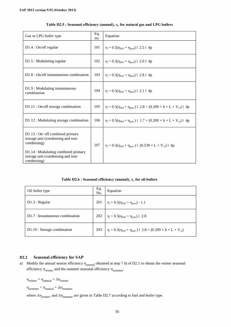
SAP 2012 version 9.92 (October 2013)
56
Table D2.5 : Seasonal efficiency (annual), η, for natural gas and LPG boilers
Gas or LPG boiler type Eq. no. Equation
D1.4 : On/off regular
101 η = 0.5(ηfull + ηpart) – 2.5 – 4p
D1.5 : Modulating regular
102 η = 0.5(ηfull + ηpart) – 2.0 – 4p
D1.8 : On/off instantaneous combination
103 η = 0.5(ηfull + ηpart) – 2.8 – 4p
D1.9 : Modulating instantaneous combination
104 η = 0.5(ηfull + ηpart) – 2.1 – 4p
D1.11 : On/off storage combination
105 η = 0.5(ηfull + ηpart ) – 2.8 + (0.209 × b × L × Vcs) – 4p
D1.12 : Modulating storage combination
106 η = 0.5(ηfull + ηpart ) – 1.7 + (0.209 × b × L × Vcs) – 4p
D1.13 : On/ off combined primary storage unit (condensing and non-condensing) D1.14 : Modulating combined primary storage unit (condensing and non-condensing)
107 η = 0.5(ηfull + ηpart ) – (0.539 × L × Vcs) – 4p
Table D2.6 : Seasonal efficiency (annual), η, for oil boilers
Oil boiler type Eq. No. Equation
D1.3 : Regular
201 η = 0.5(ηfull + ηpart) - 1.1
D1.7 : Instantaneous combination
202 η = 0.5(ηfull + ηpart) – 2.8
D1.10 : Storage combination
203 η = 0.5(ηfull + ηpart ) – 2.8 + (0.209 × b × L × Vcs)
D2.2 Seasonal efficiency for SAP a) Modify the annual season efficiency ηannual obtained at step 7 b) of D2.1 to obtain the winter seasonal
efficiency ηwinter and the summer seasonal efficiency ηsummer: ηwinter = ηannual + ∆ηwinter
ηsummer = ηannual + ∆ηsummer
where ∆ηwinter, and ∆ηsummer are given in Table D2.7 according to fuel and boiler type.
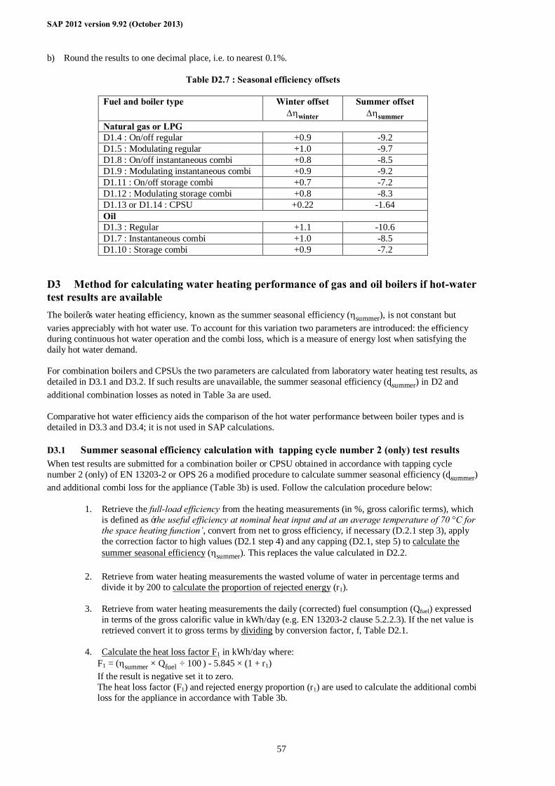
SAP 2012 version 9.92 (October 2013)
57
b) Round the results to one decimal place, i.e. to nearest 0.1%.
Table D2.7 : Seasonal efficiency offsets
Fuel and boiler type Winter offset ∆ηwinter
Summer offset ∆ηsummer
Natural gas or LPG D1.4 : On/off regular +0.9 -9.2 D1.5 : Modulating regular +1.0 -9.7 D1.8 : On/off instantaneous combi +0.8 -8.5 D1.9 : Modulating instantaneous combi +0.9 -9.2 D1.11 : On/off storage combi +0.7 -7.2 D1.12 : Modulating storage combi +0.8 -8.3 D1.13 or D1.14 : CPSU +0.22 -1.64 Oil D1.3 : Regular +1.1 -10.6 D1.7 : Instantaneous combi +1.0 -8.5 D1.10 : Storage combi +0.9 -7.2
D3 Method for calculating water heating performance of gas and oil boilers if hot-water test results are available The boiler’s water heating efficiency, known as the summer seasonal efficiency (ηsummer), is not constant but varies appreciably with hot water use. To account for this variation two parameters are introduced: the efficiency during continuous hot water operation and the combi loss, which is a measure of energy lost when satisfying the daily hot water demand. For combination boilers and CPSUs the two parameters are calculated from laboratory water heating test results, as detailed in D3.1 and D3.2. If such results are unavailable, the summer seasonal efficiency (ηsummer) in D2 and additional combination losses as noted in Table 3a are used. Comparative hot water efficiency aids the comparison of the hot water performance between boiler types and is detailed in D3.3 and D3.4; it is not used in SAP calculations.
D3.1 Summer seasonal efficiency calculation with tapping cycle number 2 (only) test results When test results are submitted for a combination boiler or CPSU obtained in accordance with tapping cycle number 2 (only) of EN 13203-2 or OPS 26 a modified procedure to calculate summer seasonal efficiency (ηsummer) and additional combi loss for the appliance (Table 3b) is used. Follow the calculation procedure below:
1. Retrieve the full-load efficiency from the heating measurements (in %, gross calorific terms), which
is defined as ‘the useful efficiency at nominal heat input and at an average temperature of 70 °C for the space heating function’, convert from net to gross efficiency, if necessary (D.2.1 step 3), apply the correction factor to high values (D2.1 step 4) and any capping (D2.1, step 5) to calculate the summer seasonal efficiency (ηsummer). This replaces the value calculated in D2.2.
2. Retrieve from water heating measurements the wasted volume of water in percentage terms and
divide it by 200 to calculate the proportion of rejected energy (r1).
3. Retrieve from water heating measurements the daily (corrected) fuel consumption (Qfuel) expressed in terms of the gross calorific value in kWh/day (e.g. EN 13203-2 clause 5.2.2.3). If the net value is retrieved convert it to gross terms by dividing by conversion factor, f, Table D2.1.
4. Calculate the heat loss factor F1 in kWh/day where:
F1 = (ηsummer × Qfuel ÷ 100 ) - 5.845 × (1 + r1) If the result is negative set it to zero. The heat loss factor (F1) and rejected energy proportion (r1) are used to calculate the additional combi loss for the appliance in accordance with Table 3b.
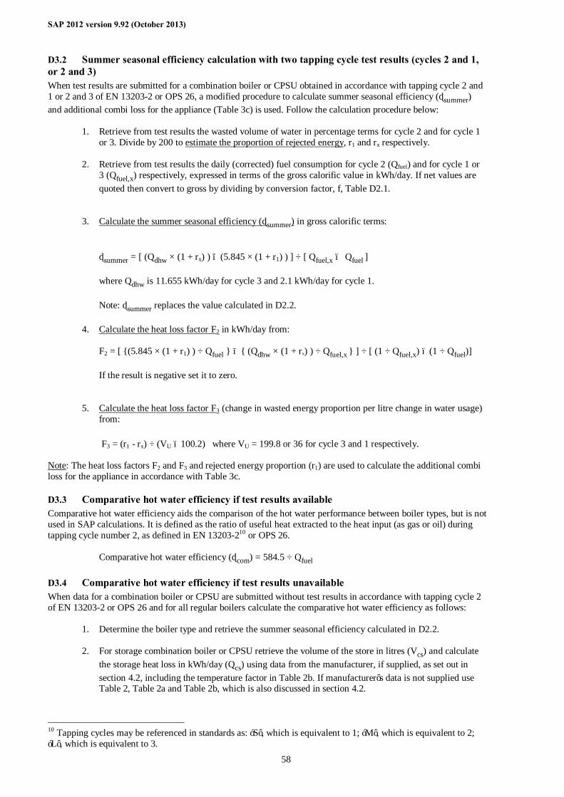
SAP 2012 version 9.92 (October 2013)
58
D3.2 Summer seasonal efficiency calculation with two tapping cycle test results (cycles 2 and 1, or 2 and 3) When test results are submitted for a combination boiler or CPSU obtained in accordance with tapping cycle 2 and 1 or 2 and 3 of EN 13203-2 or OPS 26, a modified procedure to calculate summer seasonal efficiency (ηsummer) and additional combi loss for the appliance (Table 3c) is used. Follow the calculation procedure below:
1. Retrieve from test results the wasted volume of water in percentage terms for cycle 2 and for cycle 1 or 3. Divide by 200 to estimate the proportion of rejected energy, r1 and rx respectively.
2. Retrieve from test results the daily (corrected) fuel consumption for cycle 2 (Qfuel) and for cycle 1 or 3 (Qfuel,x) respectively, expressed in terms of the gross calorific value in kWh/day. If net values are quoted then convert to gross by dividing by conversion factor, f, Table D2.1.
3. Calculate the summer seasonal efficiency (ηsummer) in gross calorific terms:
ηsummer = [ (Qdhw × (1 + rx) ) − (5.845 × (1 + r1) ) ] ÷ [ Qfuel,x – Qfuel ] where Qdhw is 11.655 kWh/day for cycle 3 and 2.1 kWh/day for cycle 1. Note: ηsummer replaces the value calculated in D2.2.
4. Calculate the heat loss factor F2 in kWh/day from: F2 = [ {(5.845 × (1 + r1) ) ÷ Qfuel } − { (Qdhw × (1 + rx) ) ÷ Qfuel,x } ] ÷ [ (1 ÷ Qfuel,x) – (1 ÷ Qfuel)] If the result is negative set it to zero.
5. Calculate the heat loss factor F3 (change in wasted energy proportion per litre change in water usage) from:
F3 = (r1 - rx) ÷ (VU – 100.2) where VU = 199.8 or 36 for cycle 3 and 1 respectively.
Note: The heat loss factors F2 and F3 and rejected energy proportion (r1) are used to calculate the additional combi loss for the appliance in accordance with Table 3c.
D3.3 Comparative hot water efficiency if test results available Comparative hot water efficiency aids the comparison of the hot water performance between boiler types, but is not used in SAP calculations. It is defined as the ratio of useful heat extracted to the heat input (as gas or oil) during tapping cycle number 2, as defined in EN 13203-210 or OPS 26.
Comparative hot water efficiency (ηcom) = 584.5 ÷ Qfuel
D3.4 Comparative hot water efficiency if test results unavailable When data for a combination boiler or CPSU are submitted without test results in accordance with tapping cycle 2 of EN 13203-2 or OPS 26 and for all regular boilers calculate the comparative hot water efficiency as follows:
1. Determine the boiler type and retrieve the summer seasonal efficiency calculated in D2.2.
2. For storage combination boiler or CPSU retrieve the volume of the store in litres (Vcs) and calculate the storage heat loss in kWh/day (Qcs) using data from the manufacturer, if supplied, as set out in section 4.2, including the temperature factor in Table 2b. If manufacturer’s data is not supplied use Table 2, Table 2a and Table 2b, which is also discussed in section 4.2.
10 Tapping cycles may be referenced in standards as: ‘S’, which is equivalent to 1; ‘M’, which is equivalent to 2; ‘L’, which is equivalent to 3.
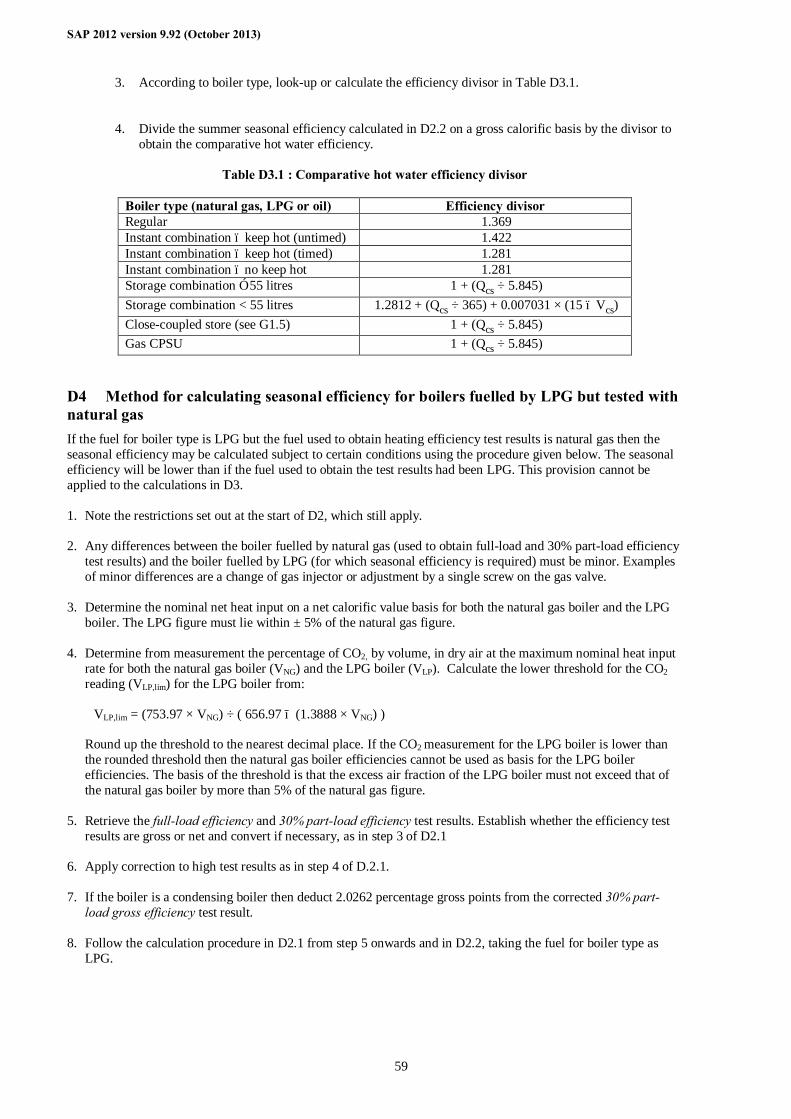
SAP 2012 version 9.92 (October 2013)
59
3. According to boiler type, look-up or calculate the efficiency divisor in Table D3.1.
4. Divide the summer seasonal efficiency calculated in D2.2 on a gross calorific basis by the divisor to obtain the comparative hot water efficiency.
Table D3.1 : Comparative hot water efficiency divisor
Boiler type (natural gas, LPG or oil) Efficiency divisor Regular 1.369 Instant combination – keep hot (untimed) 1.422 Instant combination – keep hot (timed) 1.281 Instant combination – no keep hot 1.281 Storage combination ≥ 55 litres 1 + (Qcs ÷ 5.845) Storage combination < 55 litres 1.2812 + (Qcs ÷ 365) + 0.007031 × (15 – Vcs) Close-coupled store (see G1.5) 1 + (Qcs ÷ 5.845) Gas CPSU 1 + (Qcs ÷ 5.845)
D4 Method for calculating seasonal efficiency for boilers fuelled by LPG but tested with natural gas If the fuel for boiler type is LPG but the fuel used to obtain heating efficiency test results is natural gas then the seasonal efficiency may be calculated subject to certain conditions using the procedure given below. The seasonal efficiency will be lower than if the fuel used to obtain the test results had been LPG. This provision cannot be applied to the calculations in D3. 1. Note the restrictions set out at the start of D2, which still apply. 2. Any differences between the boiler fuelled by natural gas (used to obtain full-load and 30% part-load efficiency
test results) and the boiler fuelled by LPG (for which seasonal efficiency is required) must be minor. Examples of minor differences are a change of gas injector or adjustment by a single screw on the gas valve.
3. Determine the nominal net heat input on a net calorific value basis for both the natural gas boiler and the LPG
boiler. The LPG figure must lie within ± 5% of the natural gas figure. 4. Determine from measurement the percentage of CO2, by volume, in dry air at the maximum nominal heat input
rate for both the natural gas boiler (VNG) and the LPG boiler (VLP). Calculate the lower threshold for the CO2 reading (VLP,lim) for the LPG boiler from:
VLP,lim = (753.97 × VNG) ÷ ( 656.97 − (1.3888 × VNG) )
Round up the threshold to the nearest decimal place. If the CO2 measurement for the LPG boiler is lower than the rounded threshold then the natural gas boiler efficiencies cannot be used as basis for the LPG boiler efficiencies. The basis of the threshold is that the excess air fraction of the LPG boiler must not exceed that of the natural gas boiler by more than 5% of the natural gas figure.
5. Retrieve the full-load efficiency and 30% part-load efficiency test results. Establish whether the efficiency test
results are gross or net and convert if necessary, as in step 3 of D2.1 6. Apply correction to high test results as in step 4 of D.2.1. 7. If the boiler is a condensing boiler then deduct 2.0262 percentage gross points from the corrected 30% part-
load gross efficiency test result. 8. Follow the calculation procedure in D2.1 from step 5 onwards and in D2.2, taking the fuel for boiler type as
LPG.
SAP 2012 version 9.92 (October 2013)
60
D5 Method for calculating Seasonal Efficiency and Case Emission value of a twin-burner range cooker boiler 1. The method of calculation of the Seasonal Efficiency is applicable only to cooker boilers for which the full load
and the 30% part load efficiency values for the boiler function, obtained by the methods deemed to satisfy Council Directive 92/42/EEC, are available.
Note: A range cooker boiler which does not have the capability to provide domestic hot water directly (i.e. is not a combination boiler), but which may nevertheless provide domestic hot water indirectly via a separate hot water storage cylinder exactly matches the definition D1.3 for a Regular Boiler. Consequently the methods deemed to satisfy 92/42/EEC for a Regular Boiler will equally satisfy this requirement for the equivalent type of range cooker boiler.
These efficiencies are for the heat transferred to water and are carried out with the cooker burner turned off.
When undertaking the efficiency test, record - input power (net) at full load conditions, Φinput,net, in kW. - heat transfer to the water under full load conditions, Φwater, in kW - flue loss (net) under full load conditions, Φflue,net, in kW according to the method given in EN 304:1992 +
Amendment 1: 1998 or other method assured by the independent test laboratory as providing comparable results for the product under test.
2. Calculate the seasonal efficiencies according to D2 using the appropriate equation for a regular boiler. 3. Calculate the case heat emission at full load from Φcase = Φinput,net – Φwater -Φflue,net
where Φwater is the heat transferred to water under full load conditions; Φflue,net is the flue gas loss measured according to BS EN 304.
4. If Φcase < 0.2 kW and the case temperatures of the range cooker are below 80°C, the case emission may, as an alternative, be derived from measurements of the case temperatures according to Supplement 1 to OFTEC Standard OFS A101, subject to a maximum figure of Φcase = 0.2 kW. Note: Supplement 1 to OFTEC Standard OFS A101 (applicable for oil and gas) can be obtained from OFTEC (Oil Firing Technical Association), Tel 0845 6585080, Fax 0845 6585181, e-mail [email protected]
5. If Φcase exceeds either of 0.05 × Φwater or 1 kW, reduce Φcase to 0.05 × Φwater or 1 kW (whichever is the
smaller).
6. Provide the values of Φcase and Φwater in kW as part of the test report.
D6 Conversion of SEDBUK values obtained for SAP 2005 Where the full-load efficiency and 30% part-load efficiency test results for a gas or oil boiler are not available it is possible to derive efficiencies for SAP 2012 from a SEDBUK value calculated as specified in SAP 2005. However, the method is approximate and better results will be obtained from following the procedure in D2.1. 1. Determine fuel for boiler type The fuel for boiler type must be one of natural gas, LPG (butane or propane), or oil (kerosene or gas oil). 2. Determine boiler type Determine the boiler type from the first column of Table D6.1, referring to the definitions in D1. If it is not known whether the boiler is on/off or modulating assume that it is on/off. Note the coefficients k1 and k2 for the boiler type in Table D6.1.
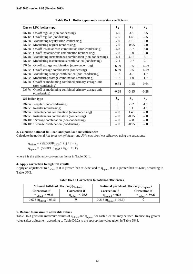
SAP 2012 version 9.92 (October 2013)
61
Table D6.1 : Boiler types and conversion coefficients
Gas or LPG boiler type k1 k2 k3
D6.1n : On/off regular (non-condensing) -6.5 3.8 -6.5 D6.1c : On/off regular (condensing) -2.5 1.45 -2.5 D6.2n : Modulating regular (non-condensing) -2.0 3.15 -2.0 D6.2c : Modulating regular (condensing) -2.0 -0.95 -2.0 D6.3n : On/off instantaneous combination (non-condensing) -6.8 -3.7 -6.8 D6.3c : On/off instantaneous combination (condensing) -2.8 -5.0 -2.8 D6.4n : Modulating instantaneous combination (non-condensing) -6.1 4.15 -6.1 D6.4c : Modulating instantaneous combination (condensing) -2.1 -0.7 -2.1 D6.5n : On/off storage combination (non-condensing) -6.59 -0.5 -6.59 D6.5c : On/off storage combination (condensing) -6.59 -0.5 -6.59 D6.6n : Modulating storage combination (non-condensing) -1.7 3.0 -1.7 D6.6c : Modulating storage combination (condensing) -1.7 -1.0 -1.7 D6.7n : On/off or modulating combined primary storage unit (non-condensing) -0.64 -1.25 -0.64
D6.7c : On/off or modulating combined primary storage unit (condensing) -0.28 -3.15 -0.28
Oil boiler type k1 k2 k3
D6.8n : Regular (non-condensing) 0 -5.2 -1.1 D6.8c : Regular (condensing) 0 1.1 -1.1 D6.9n : Instantaneous combination (non-condensing) -2.8 1.45 -2.8 D6.9c : Instantaneous combination (condensing) -2.8 -0.25 -2.8 D6.10n : Storage combination (non-condensing) -2.8 -2.8 -2.8 D6.10c : Storage combination (condensing) -2.8 -0.95 -2.8
3. Calculate notional full-load and part-load net efficiencies Calculate the notional full-load net efficiency and 30% part-load net efficiency using the equations:
ηnflnet = (SEDBUK2005 – k1) ÷ f + k2 ηnplnet = (SEDBUK2005 – k1) ÷ f – k2
where f is the efficiency conversion factor in Table D2.1. 4. Apply correction to high test results Apply an adjustment to ηnflnet if it is greater than 95.5 net and to ηnplnet if it is greater than 96.6 net, according to Table D6.2.
Table D6.2 : Correction to notional efficiencies
Notional full-load efficiency(ηnflnet) Notional part-load efficiency (ηnplnet) Correction if
ηnflnet > 95.5 Correction if
ηnflnet ≤ 95.5 Correction if
ηnplnet > 96.6 Correction if
ηnplnet ≤ 96.6 - 0.673 (ηnflnet – 95.5) 0 - 0.213 (ηnplnet – 96.6) 0
5. Reduce to maximum allowable values Table D6.3 gives the maximum values of ηnflnet and ηnplnet for each fuel that may be used. Reduce any greater value (after adjustment according to Table D6.2) to the appropriate value given in Table D6.3.
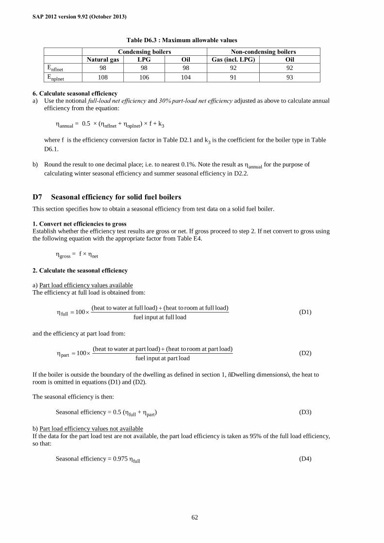
SAP 2012 version 9.92 (October 2013)
62
Table D6.3 : Maximum allowable values
Condensing boilers Non-condensing boilers Natural gas LPG Oil Gas (incl. LPG) Oil Enflnet 98 98 98 92 92 Enplnet 108 106 104 91 93
6. Calculate seasonal efficiency a) Use the notional full-load net efficiency and 30% part-load net efficiency adjusted as above to calculate annual
efficiency from the equation:
ηannual = 0.5 × (ηnflnet + ηnplnet) × f + k3 where f is the efficiency conversion factor in Table D2.1 and k3 is the coefficient for the boiler type in Table
D6.1. b) Round the result to one decimal place; i.e. to nearest 0.1%. Note the result as ηannual for the purpose of
calculating winter seasonal efficiency and summer seasonal efficiency in D2.2.
D7 Seasonal efficiency for solid fuel boilers This section specifies how to obtain a seasonal efficiency from test data on a solid fuel boiler. 1. Convert net efficiencies to gross Establish whether the efficiency test results are gross or net. If gross proceed to step 2. If net convert to gross using the following equation with the appropriate factor from Table E4.
ηgross = f × ηnet 2. Calculate the seasonal efficiency a) Part load efficiency values available The efficiency at full load is obtained from:
load fullat input fuelload) fullat room (heat to load) fullat water (heat to100full
+×=η (D1)
and the efficiency at part load from:
loadpart at input fuelload)part at room (heat to load)part at water (heat to100part
+×=η (D2)
If the boiler is outside the boundary of the dwelling as defined in section 1, “Dwelling dimensions”, the heat to room is omitted in equations (D1) and (D2). The seasonal efficiency is then:
Seasonal efficiency = 0.5 (ηfull + ηpart) (D3) b) Part load efficiency values not available If the data for the part load test are not available, the part load efficiency is taken as 95% of the full load efficiency, so that:
Seasonal efficiency = 0.975 ηfull (D4)
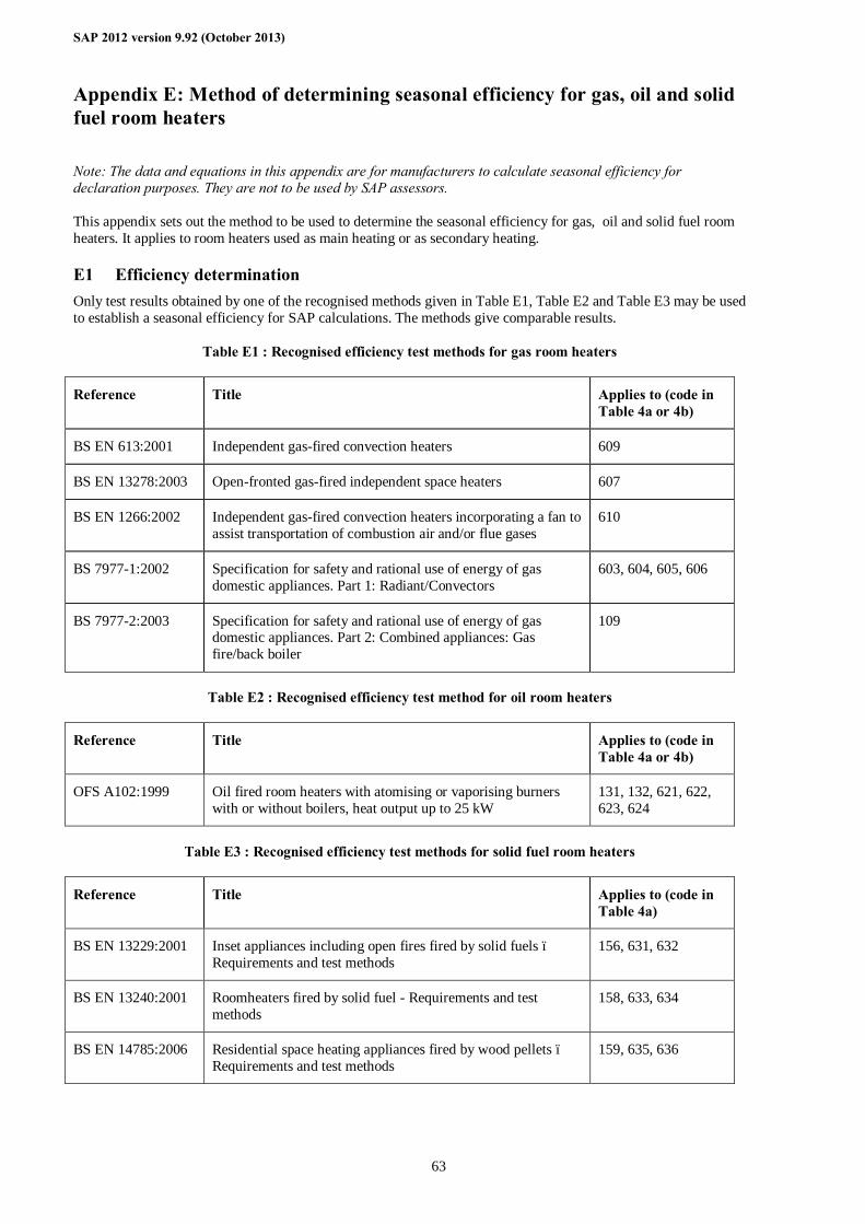
SAP 2012 version 9.92 (October 2013)
63
Appendix E: Method of determining seasonal efficiency for gas, oil and solid fuel room heaters
Note: The data and equations in this appendix are for manufacturers to calculate seasonal efficiency for declaration purposes. They are not to be used by SAP assessors. This appendix sets out the method to be used to determine the seasonal efficiency for gas, oil and solid fuel room heaters. It applies to room heaters used as main heating or as secondary heating.
E1 Efficiency determination Only test results obtained by one of the recognised methods given in Table E1, Table E2 and Table E3 may be used to establish a seasonal efficiency for SAP calculations. The methods give comparable results.
Table E1 : Recognised efficiency test methods for gas room heaters
Reference Title Applies to (code in Table 4a or 4b)
BS EN 613:2001 Independent gas-fired convection heaters 609
BS EN 13278:2003 Open-fronted gas-fired independent space heaters 607
BS EN 1266:2002 Independent gas-fired convection heaters incorporating a fan to assist transportation of combustion air and/or flue gases
610
BS 7977-1:2002 Specification for safety and rational use of energy of gas domestic appliances. Part 1: Radiant/Convectors
603, 604, 605, 606
BS 7977-2:2003 Specification for safety and rational use of energy of gas domestic appliances. Part 2: Combined appliances: Gas fire/back boiler
109
Table E2 : Recognised efficiency test method for oil room heaters
Reference Title Applies to (code in Table 4a or 4b)
OFS A102:1999 Oil fired room heaters with atomising or vaporising burners with or without boilers, heat output up to 25 kW
131, 132, 621, 622, 623, 624
Table E3 : Recognised efficiency test methods for solid fuel room heaters
Reference Title Applies to (code in Table 4a)
BS EN 13229:2001 Inset appliances including open fires fired by solid fuels – Requirements and test methods
156, 631, 632
BS EN 13240:2001 Roomheaters fired by solid fuel - Requirements and test methods
158, 633, 634
BS EN 14785:2006 Residential space heating appliances fired by wood pellets – Requirements and test methods
159, 635, 636
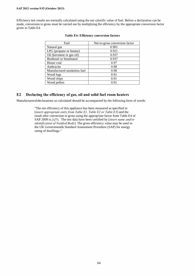
SAP 2012 version 9.92 (October 2013)
64
Efficiency test results are normally calculated using the net calorific value of fuel. Before a declaration can be made, conversion to gross must be carried out by multiplying the efficiency by the appropriate conversion factor given in Table E4.
Table E4: Efficiency conversion factors
Fuel Net-to-gross conversion factor Natural gas 0.901 LPG (propane or butane) 0.921 Oil (kerosene or gas oil) 0.937 Biodiesel or bioethanol 0.937 House coal 0.97 Anthracite 0.98 Manufactured smokeless fuel 0.98 Wood logs 0.91 Wood chips 0.91 Wood pellets 0.91
E2 Declaring the efficiency of gas, oil and solid fuel room heaters Manufacturers’ declarations so calculated should be accompanied by the following form of words:
"The net efficiency of this appliance has been measured as specified in [insert appropriate entry from Table E1, Table E2 or Table E3] and the result after conversion to gross using the appropriate factor from Table E4 of SAP 2009 is [x]%. The test data have been certified by [insert name and/or identification of Notified Body]. The gross efficiency value may be used in the UK Government’s Standard Assessment Procedure (SAP) for energy rating of dwellings."
SAP 2012 version 9.92 (October 2013)
65
Appendix F: Electric CPSUs
An electric CPSU is a central heating system providing space and domestic water heating. Primary water heated mainly or entirely during low-rate periods is stored in a thermal store. It can use the electric 10-hour or 18-hour tariff.
The space heating circuit operates in the same way as a wet central heating system, with controls appropriate for wet systems. For domestic hot water, secondary water flows directly from the cold mains into a heat exchanger, where it is heated by the hot water in the store before being delivered to the taps.
The heat losses from the CPSU are calculated, as for other hot water storage vessels, in Section 4 of the calculation, using data from Table 2 or Table 2b.
F1 Electric CPSUs using 10-hour electricity tariff The CPSU draws some electricity at the high rate and some at the low rate. The high-rate fraction is calculated as follows. The procedure below applies to worksheet (201) onwards. 1. Calculate the high-rate fraction (for each month) using the following methodology:
a) Calculate minimum external temperature for which the stored heat can satisfy the demand temperature
[ ] [ ]m
mmmmaxmmmin )39(
)95()n24()45(1000C)93()39(T
−×÷×+−×= (F1)
nm is the number of days in the month. Cmax is the low-rate heat available irrespective of power rating of the
heating element, calculated using the formula:
Cmax = 0.1456 × Vcs × (Tw – 48) (F2)
where Vcs is the CPSU capacity in litres and Tw is winter operating temperature in °C.
In equations (F1) to (F4) items written as (39)m etc. are references to worksheet numbers.
b) Calculate high-rate energy required
if Tmin – Te = 0, mmpeakon n)39(024.0E ××=−
otherwise ( )
( ))TT(exp1TTn)39(024.0
Eemin
eminmmpeakon −−−
−×××=− (F3)
where Te is the external temperature for month m.
2. For June to September (water heating only) set the high-rate fraction to 0. For other months calculate the high-rate fraction
mm
peakon
)45()98(E
F+
= − (F4)
3. Apply the high-rate price to fraction F of the heating requirement (both space and water) and the low-rate price to fraction (1 – F).
4. Enter the applicable value for central heating pump (Table 4f) in worksheet (230c).
F2 Electric CPSUs using 18-hour electricity tariff The 18-hour low rate applies to all space heating and water heating provided by the CPSU. The CPSU must have sufficient energy stored to provide heating during a 2-hour shut-off period. The 18-hour high rate applies to all other electricity uses.
SAP 2012 version 9.92 (October 2013)
66
Appendix G: Flue gas heat recovery systems and Waste water heat recovery systems
G1 Flue gas heat recovery systems (FGHRS) When fitted to a condensing boiler a flue gas heat recovery system (FGHRS) recovers heat from the flue products to pre-heat the domestic hot water supply. Passive flue gas heat recovery devices (PFGHRD)11 are a subset of FGHRS. The boiler can be fired by mains gas, LPG or oil. The heat recovered is mostly from condensation of water vapour in the flue products and the application of an FGHRS is restricted to condensing boilers because non-condensing types are not generally adequately protected against the corrosive effects of condensate. For non-condensing boiler they would also alter the buoyancy characteristics of the combustion products posing a potential safety hazard. Where the device has a heat store, energy recovered during space heating production can also be used to later offset the heat required for providing domestic hot water. Data for FGHRS are brought into SAP calculations via the database. The SAP assessor selects the FGHRS being used from a list offered by the software, identifying the device by means of brand name and model. The software then fetches the parameters needed from the database. When there is an FGHRS the adjustments to boiler efficiency given in Table 4c for low temperature heat emitters and load/weather compensator are not applied even if present as there would be double counting if they were. A FGHRS is an option if: - main heating is from a boiler fired by mains gas, LPG or oil, and - the boiler is a condensing type, and - the fuel to which the FGHRS data apply is the same as the boiler fuel, and - the boiler type is one of those to which the FGHRS data apply. It is not relevant if the above conditions do not apply. Note. The gains from the water heating system (65)m must be calculated before the calculation of space heating. If there is an FGHRS the output from the water heater (64)m is amended after calculation of space heating to include (63)m. If there is also a WWHRS see section G4.
G1.1 FGHRS without an FGHRS heat store If the FGHRS has no heat store calculate the saving in each month by:
Sm = Kf1 × Kn × Qhw,m (G1) where
Sm is the saving in month m due to the FGHRS; Kf1 is the useful fraction of heat recovered directly in a hot-water-only test (from database record); Kn is defined by (G7) below; Qhw,m is the energy content of water heated by the boiler in month m. This is worksheet (45)m less any saving
for a WWHRS calculated by equation (G10) and less any solar input calculated by equation (H2) in Appendix H.
G1.2 FGHRS with an FGHRS heat store The heat store is within the FGHRS. In addition there can be a close-coupled external store (see G1.5) which can be heated also by a PV array (see G1.6). The energy saving depends on the monthly hot water usage and space heating requirement. A data record for an FGHRS includes two sets of coefficients a, b and c defining a set of equations relating energy saving in kWh to hot
11 A PFGHRD is passive (does not consume electricity) whereas an FGHRS may do; also a PFGHRD is a single component whereas an FGHRS may consist of separate individual components that are not contained within a single package when installed.
SAP 2012 version 9.92 (October 2013)
67
water provided by the boiler, Qhw,m, for different space heating requirements (typically 6 equations). One set of coefficients applies to instantaneous combi boilers without a keep-hot facility and without an external store, the other applies to all other boiler types (having a heat store within or external to the boiler). If there is also a WWHRS see section G4 below. If Qhw,m ≤ 0 set the saving for month m to zero. Otherwise the equations, valid in the range 80 ≤ Qhw,m ≤ 309, are of the form:
S0,m = a × ln(Qhw,m) + b × Qhw,m + c (G2) where
S0,m is the energy saving in month m, in kWh Qhw,m is the energy content of water heated by the boiler in month m. This is worksheet (45)m less any saving
for a WWHRS calculated by equation (G10) and less any solar input calculated by equation (H2) in Appendix H.
ln denotes natural logarithm If Qhw,m < 80, use equation (G2) with Qhw,m = 80 and multiply the result by Qhw,m ÷ 80 If Qhw,m > 309, use equation (G2) with Qhw,m = 309. For each fuel for which the device has been tested there is a database record containing:
a) whether an internal or external heat store is fitted; b) the useful fraction of heat recovered directly in a hot-water-only test, Kf1, for use with an instantaneous
combi boiler without a keep hot facility and without a close-coupled external store; c) the total fraction of heat recovered directly in a hot-water-only test, Kf2, for use with all other boiler types; d) annual electrical consumption in kWh/year, if any; e) first set of coefficients a, b and c for a range of space heating requirements applicable to an instantaneous
combi boiler without a keep-hot facility and without a close-coupled external store (assumes the FGHRS reduces the amount of luke-warm water rejected);
f) second set of coefficients a, b and c for a range of space heating requirements applicable to all other boiler types and combi configurations (assumes no water is rejected).
The procedure is defined by steps 1) to 8). 1) Obtain the 12 monthly space heating requirements of the main heating system, Qsp,m (values for the months
June to September are zero).
If fitted to the first main heating system:
Qsp,m = (98)m × (204) (G3) If fitted to the second main heating system:
Qsp,m = (98)m × (205) (G4)
Qsp,m = 0 if the boiler with the FGHRS does not provide space heating.
2) From the database record, obtain the coefficients a, b and c for the space heating requirement immediately above (Qsp1,m) and below (Qsp2,m) the actual monthly space heating requirements Qsp,m. If the boiler is an instantaneous combi without keep-hot facility and without a close-coupled external store (see G1.5) use the first set of coefficients a, b and c; for any other type of boiler use the second set of coefficients and apply a correction according to the water storage arrangement in step 7). If Qsp,m is exactly equal to a value in the database omit steps 3) and 4) and use the corresponding coefficients to calculate the monthly savings, S0,m, according to equation (G2).
3) Calculate the estimated monthly saving for the space heating requirements immediately above (Qsp1,m) and below (Qsp2,m) the actual requirement using equation (G2).
4) Using linear interpolation, calculate the monthly saving, S0,m, for the each monthly space heating requirement (Qsp,m) of the main heating system from the saving for space heating requirements immediately above (Qsp1,m) and below (Qsp2,m).
SAP 2012 version 9.92 (October 2013)
68
5) If S0,m is negative set it to zero.
6) If Qsp,m is greater than the largest value of space heating requirement in the database record, calculate the saving using the equation for the largest value of space heating requirement in the database record.
7) For instantaneous combi boilers without a keep-hot facility and not connected to a close-coupled hot-water store (see G1.5), set Sm = S0,m and omit this step.
Otherwise amend the savings to include the heat recovered while heating the hot-water store according to the water storage arrangement as follows.
a. In the case of a combi boiler with keep-hot facility,
Sm = S0,m + 0.5 × Kf2 × ( Qc,m – Qce,m) (G5) where
Sm is the saving in month m due to the FGHRS; S0,m is the saving calculated at step 4); Kf2 is the total fraction of heat recovered directly in a hot-water-only test; Qc,m is the applicable combi loss in month m (Table 3a, 3b or 3c) as at (61)m ; Qce,m is the electrical energy used in month m by the keep-hot (Table 4f), if any; 0.5 allows for the lower heat transfer to the FGHRS store compared to heat transfer directly to the cold
water feed.
b. If the boiler is a storage combi, a regular boiler supplying a cylinder or thermal store, a CPSU, or an instantaneous combi connected to a close-coupled external store,
If Qhw,m ≤ 0 set Sm = 0, otherwise Sm = S0,m + 0.5 × Kf2 × [ Qloss,m - (1 - Kn) × Qhw,m ] (G6)
where
Sm is the saving in month m due to the FGHRS; S0,m is the saving calculated at step 4); Kf2 is the total fraction of heat recovered directly in a hot-water-only test; Qloss,m is the storage, primary and combi loss in month m, equal to (57)m + (59)m + (61)m; Kn is related to the coincidence of hot-water draw-off and boiler firing and is given by equations (G7); Qhw,m is as defined below equation (G2).
Kn = 0 if Vk ≥ 144
Kn = 0.48 – Vk ÷ 300 if 75 ≤ Vk < 144
Kn = 1.1925 – 0.77 Vk ÷ 60 if 15 < Vk < 75
Kn = 1 if Vk ≤ 15
(G7)
where
Vk is the storage volume in the case of a regular boiler, a secondary storage combi boiler or a close-coupled store;
Vk is 1.3 times the storage volume in the case of a primary storage combi or a CPSU. Note 1 In the case of a twin-coil cylinder connected to a regular boiler, Vk is the volume of the cylinder
less the dedicated volume for solar or WWHRS storage. Note 2 In the case of a close-coupled external store Vk is obtained from the database record for the
FGHRS. In other cases Vk is obtained from the database record for the boiler (if applicable) or is supplied by the SAP assessor (e.g. volume of hot-water cylinder used with a regular boiler).
G1.3 FGHRS adjustment to energy requirements for water heating Include Sm (as negative values) in the calculation of (64)m.
SAP 2012 version 9.92 (October 2013)
69
If there are two boilers each with an FGHRS fitted, apply the savings for the boiler that provides domestic hot water.
G1.4 FGHRS electrical power Some systems may require electrical power. If that is the case a non-zero value (kWh/year) is included in the database record which is added into (231).
G1.5 FGHRS using a close-coupled external store An FGHRS for an instantaneous combi boiler without a keep-hot facility may include a close-coupled external store. The store is connected to the boiler by not more than 1.5 m of insulated pipework (primary loss = 0) and its heating is controlled by a time clock (so that 0.9 is applied to the loss factor in Table 2b). In this case the characteristics of the store are used in section 4 of the SAP worksheet and the procedure in G1.2 applies using the volume of the external store (provided in the database record), heat store loss rate (provided in database record) and data from Tables 2b and 3a, 3b or 3c as indicated for an instantaneous combi with a close-coupled external store.
G1.6 FGHRS using a close-coupled external store and a directly-powered photovoltaic array The close-coupled store in FGHRS is kept warm by the combi boiler and maintained at 65°C by a separate channel that is controlled by a time clock. Electricity produced by the PV module feeds a low-voltage DC electric immersion heater within the close-coupled store via standard twin and earth mains cable. The store is subject to a maximum temperature of 85°C. There are no additional pumps and no power conversion to 230V AC. The procedure takes account of power loss in the connecting cable. For these systems the database record includes the fraction of PV power lost in the connecting cable, and user-supplied information is the installed kWp of the PV array and the orientation, tilt and overshading of the PV. Calculation of solar input The annual solar input, Qs, in kWh/year is calculated as follows. Peak power of PV array (G1) Annual solar radiation per m² from U3.3 in Appendix U for the orientation and tilt of the collector (G2)
Overshading factor from Table H2 (G3) Cable loss (provided in database record) (G4) Solar energy available 0.84 × (G1) × (G2) × (G3) × [1 - (G4)] = (G5) Solar-to-load ratio (G5) ÷ ∑ (45)m = (G6) if a WWHRS or solar water heating is fitted this becomes (G5) ÷[ ∑ (45)m – ∑Sm - Qs ] Utilisation factor if (G6) > 0, 1 - exp[-1/(G6)], otherwise enter “0” in (G7) (G7) Volume of store, Vk (provided in database record) (G8) Effective solar volume, Veff = 0.76 × (G8) (G9) Daily hot water demand, Vd,average, (litres) (G10) = (43) (G10) Volume ratio Veff/Vd,average (G9) ÷ (G10) = (G11) Solar storage volume factor f(Veff/Vd,average) 1 + 0.2 × ln(G11) = (G12) (not greater than 1.0) Annual solar input Qs (kWh) (G5) × (G7) × (G12) = (G13) Note: (43) and (45) are numbers of the main worksheet The solar input (in kWh) for month m is
Qs,m = -Qs × fm × nm /365 (G8)
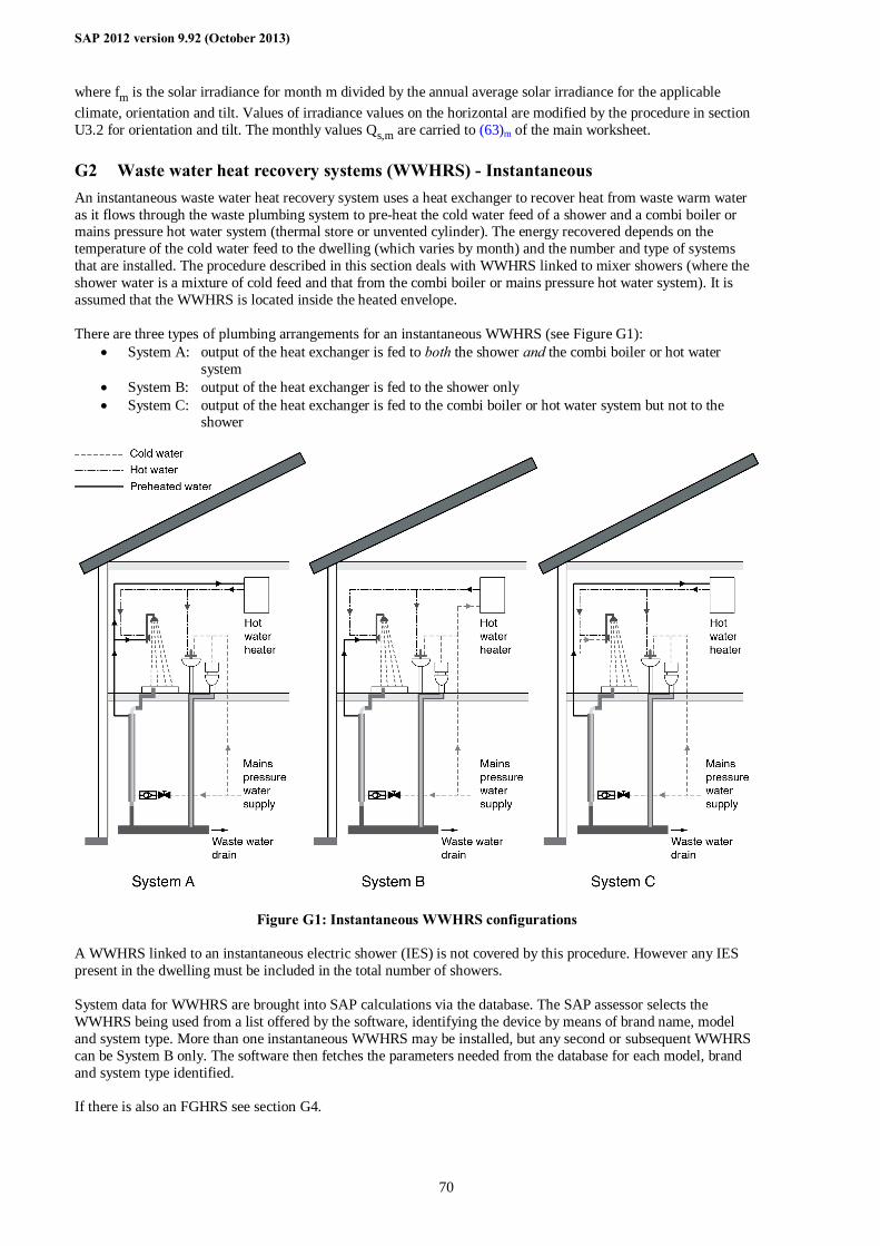
SAP 2012 version 9.92 (October 2013)
70
where fm is the solar irradiance for month m divided by the annual average solar irradiance for the applicable climate, orientation and tilt. Values of irradiance values on the horizontal are modified by the procedure in section U3.2 for orientation and tilt. The monthly values Qs,m are carried to (63)m of the main worksheet.
G2 Waste water heat recovery systems (WWHRS) - Instantaneous An instantaneous waste water heat recovery system uses a heat exchanger to recover heat from waste warm water as it flows through the waste plumbing system to pre-heat the cold water feed of a shower and a combi boiler or mains pressure hot water system (thermal store or unvented cylinder). The energy recovered depends on the temperature of the cold water feed to the dwelling (which varies by month) and the number and type of systems that are installed. The procedure described in this section deals with WWHRS linked to mixer showers (where the shower water is a mixture of cold feed and that from the combi boiler or mains pressure hot water system). It is assumed that the WWHRS is located inside the heated envelope. There are three types of plumbing arrangements for an instantaneous WWHRS (see Figure G1):
• System A: output of the heat exchanger is fed to both the shower and the combi boiler or hot water system
• System B: output of the heat exchanger is fed to the shower only • System C: output of the heat exchanger is fed to the combi boiler or hot water system but not to the
shower
Figure G1: Instantaneous WWHRS configurations A WWHRS linked to an instantaneous electric shower (IES) is not covered by this procedure. However any IES present in the dwelling must be included in the total number of showers. System data for WWHRS are brought into SAP calculations via the database. The SAP assessor selects the WWHRS being used from a list offered by the software, identifying the device by means of brand name, model and system type. More than one instantaneous WWHRS may be installed, but any second or subsequent WWHRS can be System B only. The software then fetches the parameters needed from the database for each model, brand and system type identified. If there is also an FGHRS see section G4.
SAP 2012 version 9.92 (October 2013)
71
G2.1 Dwelling-specific data required for instantaneous WWHRS Showers can be either the mixer type (fed by both hot and cold water, with a control to adjust the proportion of each) or instantaneous electric (IES) (cold water feed heated by an electric element as it runs). The energy saving depends on (a) the total number of rooms with a bath and/or a shower, including both mixer showers and IES, and (b) the number of mixer showers fitted with a WWHRS, not including any IES. The formulation below allows for two different WWHR systems (provided that the second system is System B).
Table G1 : Dwelling data required for Instantaneous WWHRS (system A, B or C) Description of parameter Symbol Total number of rooms with bath and/or shower (any type, with or without WWHRS fitted)
Nbth+sh
Number of mixer showers fitted with WWHRS1 in rooms with a bath Nsh&bth,1 Number of mixer showers fitted with WWHRS1 in rooms without a bath Nshxbth,1 Number of mixer showers fitted with WWHRS2 in rooms with a bath Nsh&bth,2 Number of mixer showers fitted with WWHRS2 in rooms without a bath Nshxbth,2
The mixer showers must have a thermostatic mixing valve. It is permissible for two showers to be connected to one WWHRS; in that case count all showers connected to that WWHRS.
G2.2 Calculation procedure for Instantaneous WWHRS 1. Obtain the fraction of bathing waste water that is routed through the heat recovery system (Fww), the utilisation
factor (UF) and heat recovery efficiency (η) for mixer showers from the database record for each system installed and calculate the average system effectiveness according to equation (G9).
Seff = [ ∑ (Nsh&bth × Fww × η × UF)1,2 + ∑ (Nshxbth × η × UF )1,2 ] ÷ Nbth+sh (G9)
2. For each month calculate the savings (kWh/month) for mixer showers with WWHRS according to equation
(G10).
Sm = [N × Aw,m + Bw,m] × Seff × (34 – Tcold,m) × 4.18 × nm × MFm ÷ 3600 (G10)
where: - if the dwelling is designed to achieve a water use target of not more than 125 litres per person per day (all
water use, hot and cold): Aw,m = [0.30 × 23.75 × ∆Tm ÷ (40 – Tcold,m)] + 23.8 Bw,m = 0.30 × 34.2 × ∆Tm ÷ (40 – Tcold,m)
- otherwise: Aw,m = [0.30 × 25 × ∆Tm ÷ (40 – Tcold,m)] + 23.8 Bw,m = 0.30 × 36 × ∆Tm ÷ (40 – Tcold,m)
Tcold,m is the temperature of the cold water feed in month m (see Table G2) nm is the number of days per month from Table 1a MFm is the monthly hot water use factor from Table 1c ∆Tm is the temperature rise of hot water drawn off from Table 1d N is the number of occupants as at worksheet (42)
3. Include Sm (as negative values) in the calculation of (64)m.
Table G2 : Cold water temperatures (°C)
Jan Feb Mar Apr May Jun Jul Aug Sept Oct Nov Dec 11.1 10.8 11.8 14.7 16.1 18.2 21.3 19.2 18.8 16.3 13.3 11.8
G2.3 Solar water heating utilisation factor adjustment for Instantaneous WWHRS WWHRS reduces the hot water demand and hence decreases the solar utilisation factor (H8) in Appendix H. When there is a WWHRS the solar-to-load ratio is as follows:
SAP 2012 version 9.92 (October 2013)
72
(H8) = (H7) ÷ [(H7a) × ∑ (45)m – ∑Sm ] (G11)
where summations are over the 12 months of the year.
G3 Waste water heat recovery systems (WWHRS) – Storage A Storage WWHRS is a whole-house system whereby heat is extracted from waste water from baths and showers, and used to preheat the incoming cold water to a combi boiler or hot water system. The system may include a heat exchanger circulation pump and additional accessory pumps for satisfactory operation. Unlike an instantaneous WWHRS it does not require simultaneous waste and pre-heated water flow and so is able to recover heat from bath water. It is assumed that the WWHRS is located inside the heated envelope. A storage WWHRS incorporates a storage volume, Vww, dedicated to the recovered heat. There are two types:
• Combined: the dedicated storage volume is within the dwelling’s hot water vessel • Separate: the dedicated storage volume is a separate vessel (typically for connection to instantaneous
hot water heaters such as a combi boiler) Storage WWHRS products are tested with a separate or combined hot water vessel whose specification is defined by the manufacturer. The resulting performance data are valid when the dedicated storage volume is between Vlow and Vhigh, where
- Vlow is the low end of the validity range of the dedicated storage volume; - Vhigh is the high end of the validity range of the dedicated storage volume.
If the dedicated volume is outside this range the energy savings are reduced (see G3.2 step 3). Vlow, Vhigh and the storage volume type are recorded in the database record for a Storage WWHRS.
G3.1 Dwelling-specific data required for Storage WWHRS
Table G3 : Dwelling data required for Storage WWHRS
Description of parameter Symbol Total number of baths and showers (any type), whether or not their waste water is routed through the WWHRS. A shower over a bath counts as one, not two.
Ntotal
Number of baths and showers whose waste water is routed through the WWHRS. A shower over a bath counts as one, not two.
Nrecovery
Dedicated WWHRS storage volume (litres) Vww The definition of Vww is the same as that of dedicated solar volume for solar water heating, i.e. the volume of the cylinder below the coil heated by the boiler (or other heat generator). In the case of a combined (twin coil) cylinder it is the volume of the cylinder allocated to the WWHRS, see diagram H2 b) in Appendix H. In the case of a separate dedicated store Vww is the volume of the separate store, see diagrams H2 a) and c) in Appendix H.
G3.2 Calculation procedure for Storage WWHRS 1. Obtain the fraction of bathing waste water that is routed through the heat recovery system (Fww), the utilisation
factor (UF) and heat recovery efficiency (η) for the system from the database record and calculate the average system effectiveness according to equation (G12).
Seff = (Nrecovery × Fww × η × UF) ÷ Ntotal (G12)
2. For each month calculate the savings Sm (kWh/month) according to equation (G10) in G2.2. 3. a. If the dedicated storage volume (Vww) is less than Vlow, multiply Sm by (Vww ÷ Vlow) b. If Vww is greater than Vhigh and less than 2 × Vhigh, multiply Sm by (2 – (Vww ÷ Vhigh)) c. If Vww is greater than 2 × Vhigh set Sm = 0. 4. Subtract Sm from (64)m.
SAP 2012 version 9.92 (October 2013)
73
G3.3 Storage vessel heat loss The heat loss from the volume Vww is accounted for in the heat recovery efficiency. Consequently in the case of combined storage the vessel heat loss is reduced in the SAP calculation, see calculation of worksheet (57). No such adjustment applies in the case of separate storage.
G3.4 Electricity for pump The system may use an electric pump for heat exchanger operation or other accessory pumps. From the data record obtain the daily electricity used by the system (Ed), calculate the annual electricity usage according to equation (G13) and include in worksheet at (230h) or (330h).
Eannual = 365 ×Ed (G13)
G3.5 Solar water heating and a Storage WWHRS The procedure does not allow for the case of solar water heating and a Storage WWHRS both present, and a Storage WWHRS cannot be assessed in those circumstances (set Sm as defined in G3.2 to zero for each month, and omit the WWHRS at worksheet (230h) or (330h)).
G4 Combination of FGHRS, WWHRS and solar water heating When there is both FGHRS and instantaneous WWHRS the savings from the FGHRS, WWHRS and solar water heating interact. When two or more of these items are present the calculations must be done in the following order:
1. WWHRS; 2. Solar water heating, allowing for the WWHRS in worksheet (H8) in Appendix H; 3. FGHRS, allowing for the WWHRS saving and the solar input in equations (G1), (G2) and (G6) and (if
applicable) worksheet (G6).
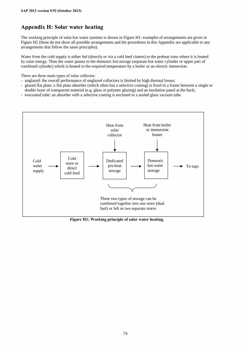
SAP 2012 version 9.92 (October 2013)
74
Appendix H: Solar water heating
The working principle of solar hot water systems is shown in Figure H1: examples of arrangements are given in Figure H2 (these do not show all possible arrangements and the procedures in this Appendix are applicable to any arrangements that follow the same principles). Water from the cold supply is either fed (directly or via a cold feed cistern) to the preheat zone where it is heated by solar energy. Then the water passes to the domestic hot storage (separate hot water cylinder or upper part of combined cylinder) which is heated to the required temperature by a boiler or an electric immersion. There are three main types of solar collector: - unglazed: the overall performance of unglazed collectors is limited by high thermal losses; - glazed flat plate: a flat plate absorber (which often has a selective coating) is fixed in a frame between a single or
double layer of transparent material (e.g. glass or polymer glazing) and an insulation panel at the back; - evacuated tube: an absorber with a selective coating is enclosed in a sealed glass vacuum tube.
Figure H1: Working principle of solar water heating.
Cold water supply
Cold store or direct
cold feed
Dedicated pre-heat storage
To taps
These two types of storage can be combined together into one store (dual fuel) or left as two separate stores
Heat from solar
collector
Heat from boiler or immersion
heater
Domestic hot water storage
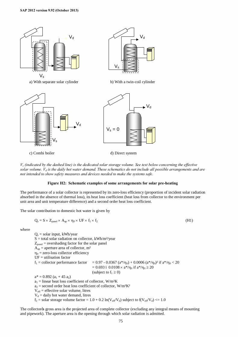
SAP 2012 version 9.92 (October 2013)
75
a) With separate solar cylinder b) With a twin-coil cylinder
c) Combi boiler d) Direct system
Vs (indicated by the dashed line) is the dedicated solar storage volume. See text below concerning the effective solar volume. Vd is the daily hot water demand. These schematics do not include all possible arrangements and are not intended to show safety measures and devices needed to make the systems safe.
Figure H2: Schematic examples of some arrangements for solar pre-heating The performance of a solar collector is represented by its zero-loss efficiency (proportion of incident solar radiation absorbed in the absence of thermal loss), its heat loss coefficient (heat loss from collector to the environment per unit area and unit temperature difference) and a second order heat loss coefficient. The solar contribution to domestic hot water is given by
Qs = S × Zpanel × Aap × η0 × UF × f1 × f2 (H1) where Qs = solar input, kWh/year S = total solar radiation on collector, kWh/m²/year Zpanel = overshading factor for the solar panel Aap = aperture area of collector, m² η0 = zero-loss collector efficiency UF = utilisation factor f1 = collector performance factor = 0.97 - 0.0367 (a*/η0) + 0.0006 (a*/η0)² if a*/η0 < 20 = 0.693 – 0.0108 × a*/η0 if a*/η0 ≥ 20 (subject to f1 ≥ 0) a* = 0.892 (a1 + 45 a2) a1 = linear heat loss coefficient of collector, W/m²K a2 = second order heat loss coefficient of collector, W/m²K² Veff = effective solar volume, litres Vd = daily hot water demand, litres f2 = solar storage volume factor = 1.0 + 0.2 ln(Veff/Vd) subject to f(Veff/Vd) <= 1.0 The collector’s gross area is the projected area of complete collector (excluding any integral means of mounting and pipework). The aperture area is the opening through which solar radiation is admitted.
Vs = 0
Vd
Vs
Vd
Vs
Vd
Vs
Vd
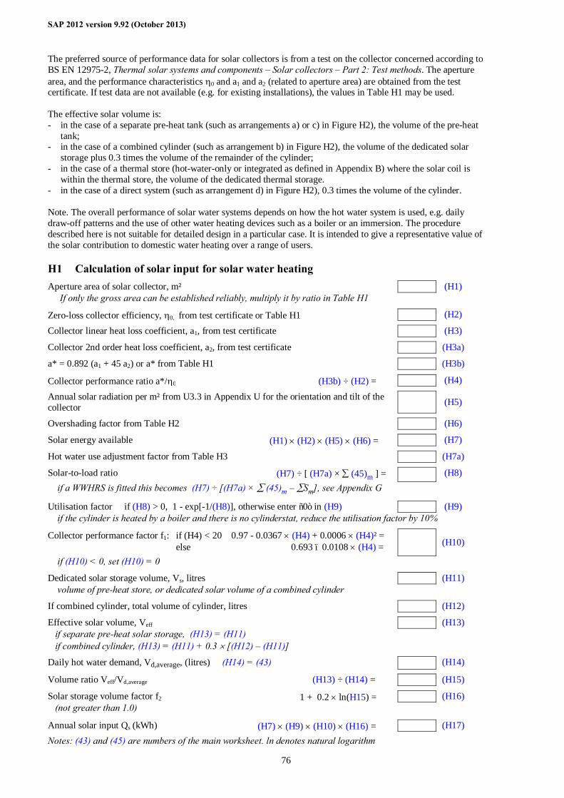
SAP 2012 version 9.92 (October 2013)
76
The preferred source of performance data for solar collectors is from a test on the collector concerned according to BS EN 12975-2, Thermal solar systems and components – Solar collectors – Part 2: Test methods. The aperture area, and the performance characteristics η0 and a1 and a2 (related to aperture area) are obtained from the test certificate. If test data are not available (e.g. for existing installations), the values in Table H1 may be used. The effective solar volume is: - in the case of a separate pre-heat tank (such as arrangements a) or c) in Figure H2), the volume of the pre-heat
tank; - in the case of a combined cylinder (such as arrangement b) in Figure H2), the volume of the dedicated solar
storage plus 0.3 times the volume of the remainder of the cylinder; - in the case of a thermal store (hot-water-only or integrated as defined in Appendix B) where the solar coil is
within the thermal store, the volume of the dedicated thermal storage. - in the case of a direct system (such as arrangement d) in Figure H2), 0.3 times the volume of the cylinder. Note. The overall performance of solar water systems depends on how the hot water system is used, e.g. daily draw-off patterns and the use of other water heating devices such as a boiler or an immersion. The procedure described here is not suitable for detailed design in a particular case. It is intended to give a representative value of the solar contribution to domestic water heating over a range of users.
H1 Calculation of solar input for solar water heating Aperture area of solar collector, m² (H1) If only the gross area can be established reliably, multiply it by ratio in Table H1 Zero-loss collector efficiency, η0, from test certificate or Table H1 (H2) Collector linear heat loss coefficient, a1, from test certificate (H3) Collector 2nd order heat loss coefficient, a2, from test certificate (H3a) a* = 0.892 (a1 + 45 a2) or a* from Table H1 (H3b) Collector performance ratio a*/η0 (H3b) ÷ (H2) = (H4) Annual solar radiation per m² from U3.3 in Appendix U for the orientation and tilt of the collector (H5)
Overshading factor from Table H2 (H6) Solar energy available (H1) × (H2) × (H5) × (H6) = (H7) Hot water use adjustment factor from Table H3 (H7a) Solar-to-load ratio (H7) ÷ [ (H7a) × ∑ (45)m ] = (H8) if a WWHRS is fitted this becomes (H7) ÷ [(H7a) × ∑ (45)m – ∑Sm], see Appendix G Utilisation factor if (H8) > 0, 1 - exp[-1/(H8)], otherwise enter “0” in (H9) (H9) if the cylinder is heated by a boiler and there is no cylinderstat, reduce the utilisation factor by 10% Collector performance factor f1: if (H4) < 20 0.97 - 0.0367 × (H4) + 0.0006 × (H4)² = else 0.693 – 0.0108 × (H4) = (H10)
if (H10) < 0, set (H10) = 0 Dedicated solar storage volume, Vs, litres (H11) volume of pre-heat store, or dedicated solar volume of a combined cylinder If combined cylinder, total volume of cylinder, litres (H12) Effective solar volume, Veff (H13) if separate pre-heat solar storage, (H13) = (H11) if combined cylinder, (H13) = (H11) + 0.3 × [(H12) – (H11)] Daily hot water demand, Vd,average, (litres) (H14) = (43) (H14) Volume ratio Veff/Vd,average (H13) ÷ (H14) = (H15) Solar storage volume factor f2 1 + 0.2 × ln(H15) = (H16) (not greater than 1.0) Annual solar input Qs (kWh) (H7) × (H9) × (H10) × (H16) = (H17) Notes: (43) and (45) are numbers of the main worksheet. ln denotes natural logarithm
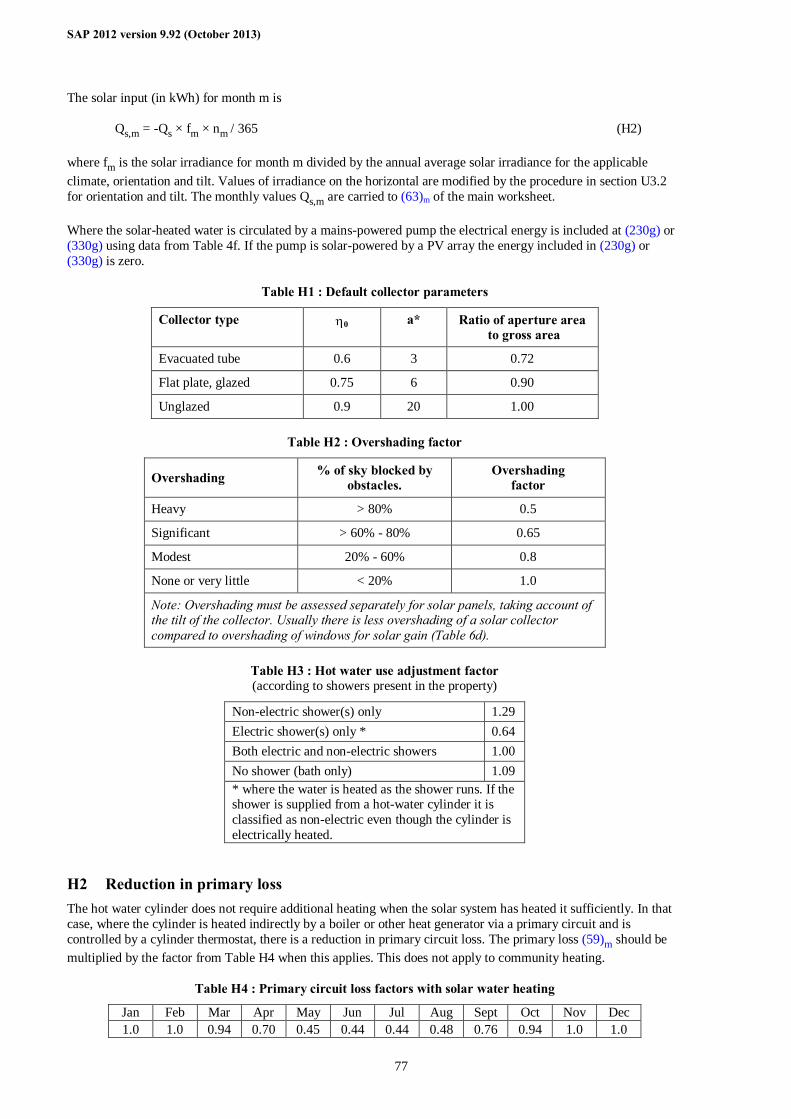
SAP 2012 version 9.92 (October 2013)
77
The solar input (in kWh) for month m is
Qs,m = -Qs × fm × nm / 365 (H2) where fm is the solar irradiance for month m divided by the annual average solar irradiance for the applicable climate, orientation and tilt. Values of irradiance on the horizontal are modified by the procedure in section U3.2 for orientation and tilt. The monthly values Qs,m are carried to (63)m of the main worksheet. Where the solar-heated water is circulated by a mains-powered pump the electrical energy is included at (230g) or (330g) using data from Table 4f. If the pump is solar-powered by a PV array the energy included in (230g) or (330g) is zero.
Table H1 : Default collector parameters
Collector type η0 a* Ratio of aperture area to gross area
Evacuated tube 0.6 3 0.72
Flat plate, glazed 0.75 6 0.90
Unglazed 0.9 20 1.00
Table H2 : Overshading factor
Overshading % of sky blocked by obstacles.
Overshading factor
Heavy > 80% 0.5
Significant > 60% - 80% 0.65
Modest 20% - 60% 0.8
None or very little < 20% 1.0
Note: Overshading must be assessed separately for solar panels, taking account of the tilt of the collector. Usually there is less overshading of a solar collector compared to overshading of windows for solar gain (Table 6d).
Table H3 : Hot water use adjustment factor (according to showers present in the property)
Non-electric shower(s) only 1.29 Electric shower(s) only * 0.64 Both electric and non-electric showers 1.00 No shower (bath only) 1.09 * where the water is heated as the shower runs. If the shower is supplied from a hot-water cylinder it is classified as non-electric even though the cylinder is electrically heated.
H2 Reduction in primary loss The hot water cylinder does not require additional heating when the solar system has heated it sufficiently. In that case, where the cylinder is heated indirectly by a boiler or other heat generator via a primary circuit and is controlled by a cylinder thermostat, there is a reduction in primary circuit loss. The primary loss (59)m should be multiplied by the factor from Table H4 when this applies. This does not apply to community heating.
Table H4 : Primary circuit loss factors with solar water heating
Jan Feb Mar Apr May Jun Jul Aug Sept Oct Nov Dec 1.0 1.0 0.94 0.70 0.45 0.44 0.44 0.48 0.76 0.94 1.0 1.0

SAP 2012 version 9.92 (October 2013)
78
H3 Community solar DHW Where solar panels are used in a community heating system, the total collector area and the total dedicated solar store volume should be divided between the dwellings in proportion to the total floor area of the dwellings (these can be rounded to the nearest 0.01 m² and 1 litre). Example. A block of 24 flats, eight with floor area of 50 m² and 16 with floor area of 60 m². Total aperture area of solar panels is 40 m² and the total solar storage volume is 1000 litres. The smaller flats are each assigned 1.47 m² and 37 litres, and the larger flats 1.76 m² and 44 litres. The calculation is done as described in H1 for single systems, with the above parameters and the orientation, pitch and overshading of the panels set at values representative of the whole installation. Usually the solar store is separate and the arrangement is equivalent to that of diagram a) in Figure H2. The reduction in primary loss in section H2 does not apply.

SAP 2012 version 9.92 (October 2013)
79
Appendix I (not used)
Appendix J (not used, see D7 for solid fuel boilers)
SAP 2012 version 9.92 (October 2013)
80
Appendix K: Thermal bridging
Thermal bridges that occur at junctions between building elements are included in the calculation of transmission heat losses. The quantity which describes the heat loss associated with a thermal bridge is its linear thermal transmittance, Ψ. This is a property of a thermal bridge and is the rate of heat flow per degree per unit length of the bridge, that is not accounted for in the U-values of the plane building elements containing the thermal bridge12. The transmission heat transfer coefficient associated with non-repeating thermal bridges is calculated as:
( )∑ Ψ×= LHTB (K1) where L is the length of the thermal bridge, in metres, over which Ψ applies. If details of the thermal bridges are not known, use
∑= expTB AyH (K2) where Aexp is the total area of external elements calculated at worksheet (31), m2, and y = 0.15 W/m²K. There are three possibilities for specifying the thermal bridging:
1) Details conform with Approved Design Details or another government-approved source involving independent assessment of the construction method. In this case - use Ψ values from the ‘approved’ column of Table K1, or - use the Ψ values provided by the approved source in equation (K1) along with the length of each junction.
Here ‘Approved Design Details’ means: - For England & Wales and for Northern Ireland: Accredited Construction Details, as listed on
www.planningportal.gov.uk/buildingregulations/approveddocuments/partl/bcassociateddocuments9/acd - For Scotland: http://www.scotland.gov.uk/Topics/Built-Environment/Building/Building-standards/techbooks/techhandbooks
2) Ψ values have been calculated by a person with suitable expertise and experience using the guidance set out in BR 497, Conventions for calculating linear thermal transmittance and temperature factors and BRE IP 1/06, Assessing the effects of thermal bridging at junctions and around openings. In this case use those calculated Ψ values in equation (K1) along with the length of each junction.
3) If neither of the above applies use equation (K2) with y = 0.15. It is possible to use both 1) and 2) together for different junctions within a given calculation. Where data via 1) or 2) are available for some junctions but not for all junctions, the values in the ‘default’ column of Table K1 should be used for those for which a linear thermal transmittance is not available. It is also permissible to use a y-value that has been calculated for a particular house design from individual Ψ values13, where each Ψ-value has been obtained via 1) or 2) above. Use this y-value in equation (K2). Documentary evidence as to the calculation of the y-value must be available. Such a y-value is applicable only to a dwelling of the size, configuration and construction for which it was calculated. For some junctions there is no ‘approved’ value. In that case use the applicable default value, or a calculated value per 2) above.
12 Repeating thermal bridges that occur throughout a building element, for example timber studs or joists, are taken
into account in the U-value of the element and so are not included here. 13 A y-value is calculated as the sum of (L × Ψ) for all junctions divided by the total area of external elements
(which includes exposed elements but not party wall).
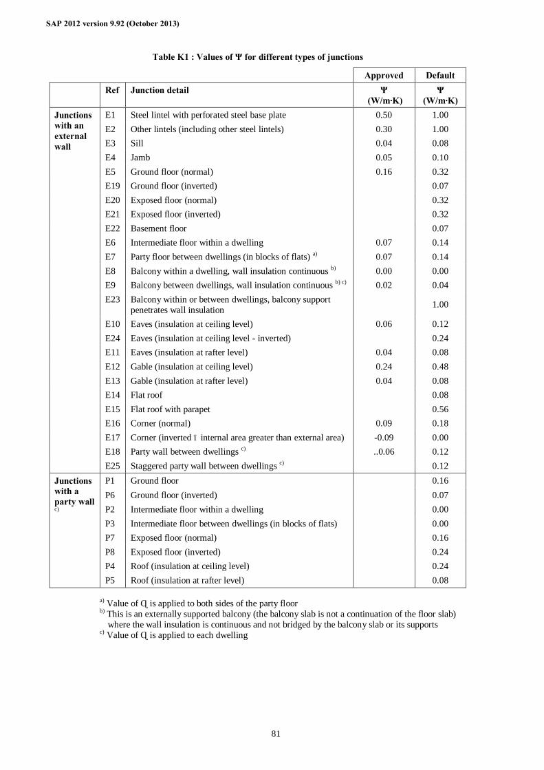
SAP 2012 version 9.92 (October 2013)
81
Table K1 : Values of Ψ for different types of junctions
Approved Default Ref Junction detail Ψ
(W/m·K) Ψ
(W/m·K) E1 Steel lintel with perforated steel base plate 0.50 1.00 E2 Other lintels (including other steel lintels) 0.30 1.00 E3 Sill 0.04 0.08 E4 Jamb 0.05 0.10 E5 Ground floor (normal) 0.16 0.32 E19 Ground floor (inverted) 0.07 E20 Exposed floor (normal) 0.32 E21 Exposed floor (inverted) 0.32 E22 Basement floor 0.07 E6 Intermediate floor within a dwelling 0.07 0.14 E7 Party floor between dwellings (in blocks of flats) a) 0.07 0.14 E8 Balcony within a dwelling, wall insulation continuous b) 0.00 0.00 E9 Balcony between dwellings, wall insulation continuous b) c) 0.02 0.04 E23 Balcony within or between dwellings, balcony support
penetrates wall insulation 1.00
E10 Eaves (insulation at ceiling level) 0.06 0.12 E24 Eaves (insulation at ceiling level - inverted) 0.24 E11 Eaves (insulation at rafter level) 0.04 0.08 E12 Gable (insulation at ceiling level) 0.24 0.48 E13 Gable (insulation at rafter level) 0.04 0.08 E14 Flat roof 0.08 E15 Flat roof with parapet 0.56 E16 Corner (normal) 0.09 0.18 E17 Corner (inverted – internal area greater than external area) -0.09 0.00 E18 Party wall between dwellings c) ..0.06 0.12
Junctions with an external wall
E25 Staggered party wall between dwellings c) 0.12 P1 Ground floor 0.16 P6 Ground floor (inverted) 0.07 P2 Intermediate floor within a dwelling 0.00 P3 Intermediate floor between dwellings (in blocks of flats) 0.00 P7 Exposed floor (normal) 0.16 P8 Exposed floor (inverted) 0.24 P4 Roof (insulation at ceiling level) 0.24
Junctions with a party wall c)
P5 Roof (insulation at rafter level) 0.08
a) Value of Ψ is applied to both sides of the party floor b) This is an externally supported balcony (the balcony slab is not a continuation of the floor slab)
where the wall insulation is continuous and not bridged by the balcony slab or its supports c) Value of Ψ is applied to each dwelling
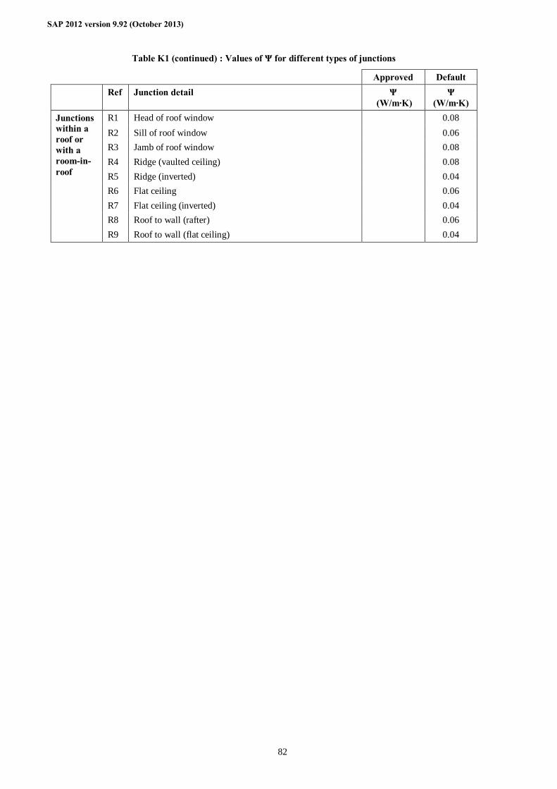
SAP 2012 version 9.92 (October 2013)
82
Table K1 (continued) : Values of Ψ for different types of junctions
Approved Default Ref Junction detail Ψ
(W/m·K) Ψ
(W/m·K) R1 Head of roof window 0.08 R2 Sill of roof window 0.06 R3 Jamb of roof window 0.08 R4 Ridge (vaulted ceiling) 0.08 R5 Ridge (inverted) 0.04 R6 Flat ceiling 0.06 R7 Flat ceiling (inverted) 0.04 R8 Roof to wall (rafter) 0.06
Junctions within a roof or with a room-in-roof
R9 Roof to wall (flat ceiling) 0.04
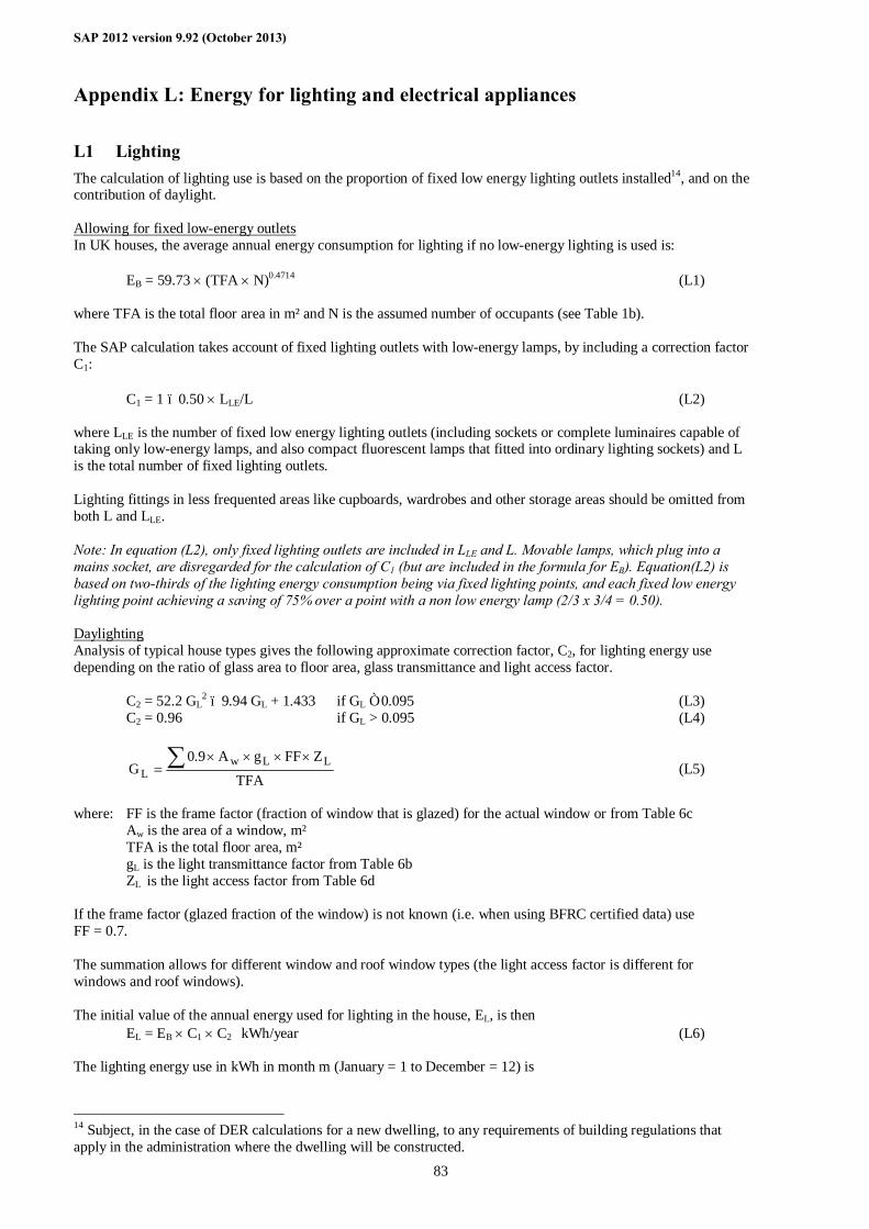
SAP 2012 version 9.92 (October 2013)
83
Appendix L: Energy for lighting and electrical appliances
L1 Lighting The calculation of lighting use is based on the proportion of fixed low energy lighting outlets installed14, and on the contribution of daylight. Allowing for fixed low-energy outlets In UK houses, the average annual energy consumption for lighting if no low-energy lighting is used is:
EB = 59.73 × (TFA × N)0.4714 (L1) where TFA is the total floor area in m² and N is the assumed number of occupants (see Table 1b). The SAP calculation takes account of fixed lighting outlets with low-energy lamps, by including a correction factor C1:
C1 = 1 – 0.50 × LLE/L (L2) where LLE is the number of fixed low energy lighting outlets (including sockets or complete luminaires capable of taking only low-energy lamps, and also compact fluorescent lamps that fitted into ordinary lighting sockets) and L is the total number of fixed lighting outlets. Lighting fittings in less frequented areas like cupboards, wardrobes and other storage areas should be omitted from both L and LLE. Note: In equation (L2), only fixed lighting outlets are included in LLE and L. Movable lamps, which plug into a mains socket, are disregarded for the calculation of C1 (but are included in the formula for EB). Equation(L2) is based on two-thirds of the lighting energy consumption being via fixed lighting points, and each fixed low energy lighting point achieving a saving of 75% over a point with a non low energy lamp (2/3 x 3/4 = 0.50). Daylighting Analysis of typical house types gives the following approximate correction factor, C2, for lighting energy use depending on the ratio of glass area to floor area, glass transmittance and light access factor.
C2 = 52.2 GL2 – 9.94 GL + 1.433 if GL ≤ 0.095 (L3)
C2 = 0.96 if GL > 0.095 (L4)
TFA
ZFFgA9.0G LLw
L∑ ××××
= (L5)
where: FF is the frame factor (fraction of window that is glazed) for the actual window or from Table 6c Aw is the area of a window, m² TFA is the total floor area, m² gL is the light transmittance factor from Table 6b ZL is the light access factor from Table 6d If the frame factor (glazed fraction of the window) is not known (i.e. when using BFRC certified data) use FF = 0.7. The summation allows for different window and roof window types (the light access factor is different for windows and roof windows). The initial value of the annual energy used for lighting in the house, EL, is then
EL = EB × C1 × C2 kWh/year (L6) The lighting energy use in kWh in month m (January = 1 to December = 12) is
14 Subject, in the case of DER calculations for a new dwelling, to any requirements of building regulations that apply in the administration where the dwelling will be constructed.
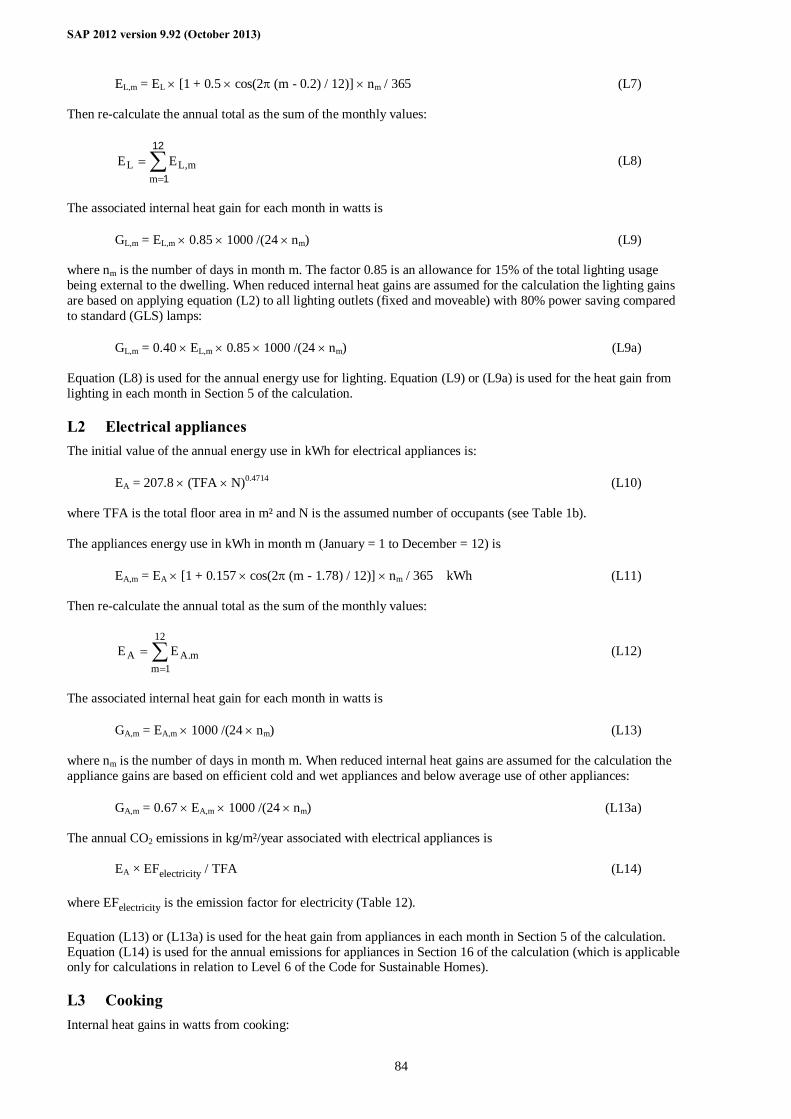
SAP 2012 version 9.92 (October 2013)
84
EL,m = EL × [1 + 0.5 × cos(2π (m - 0.2) / 12)] × nm / 365 (L7)
Then re-calculate the annual total as the sum of the monthly values:
∑=
=12
1mm,LL EE (L8)
The associated internal heat gain for each month in watts is
GL,m = EL,m × 0.85 × 1000 /(24 × nm) (L9)
where nm is the number of days in month m. The factor 0.85 is an allowance for 15% of the total lighting usage being external to the dwelling. When reduced internal heat gains are assumed for the calculation the lighting gains are based on applying equation (L2) to all lighting outlets (fixed and moveable) with 80% power saving compared to standard (GLS) lamps:
GL,m = 0.40 × EL,m × 0.85 × 1000 /(24 × nm) (L9a) Equation (L8) is used for the annual energy use for lighting. Equation (L9) or (L9a) is used for the heat gain from lighting in each month in Section 5 of the calculation.
L2 Electrical appliances The initial value of the annual energy use in kWh for electrical appliances is:
EA = 207.8 × (TFA × N)0.4714 (L10) where TFA is the total floor area in m² and N is the assumed number of occupants (see Table 1b). The appliances energy use in kWh in month m (January = 1 to December = 12) is
EA,m = EA × [1 + 0.157 × cos(2π (m - 1.78) / 12)] × nm / 365 kWh (L11) Then re-calculate the annual total as the sum of the monthly values:
∑=
=12
1mm.AA EE (L12)
The associated internal heat gain for each month in watts is
GA,m = EA,m × 1000 /(24 × nm) (L13)
where nm is the number of days in month m. When reduced internal heat gains are assumed for the calculation the appliance gains are based on efficient cold and wet appliances and below average use of other appliances:
GA,m = 0.67 × EA,m × 1000 /(24 × nm) (L13a) The annual CO2 emissions in kg/m²/year associated with electrical appliances is
EA × EFelectricity / TFA (L14) where EFelectricity is the emission factor for electricity (Table 12). Equation (L13) or (L13a) is used for the heat gain from appliances in each month in Section 5 of the calculation. Equation (L14) is used for the annual emissions for appliances in Section 16 of the calculation (which is applicable only for calculations in relation to Level 6 of the Code for Sustainable Homes).
L3 Cooking Internal heat gains in watts from cooking:

SAP 2012 version 9.92 (October 2013)
85
GC = 35 + 7 N (L15) When lower internal heat gains are assumed for the calculation,
GC = 23 + 5 N (L15a) CO2 emissions in kg/m²/year associated with cooking:
(119 + 24 N) / TFA (L16) where TFA is the total floor area in m² and N is the assumed number of occupants (see Table 1b). Equation (L15) or (L15a) is used for the heat gain from cooking in Section 5 of the calculation. Equation (L16) is used for the annual emissions for cooking in Section 16 of the calculation (which is applicable only for calculations in relation to Level 6 of the Code for Sustainable Homes and to Stamp Duty Land Tax).
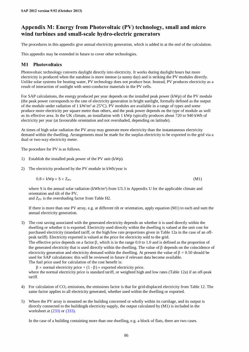
SAP 2012 version 9.92 (October 2013)
86
Appendix M: Energy from Photovoltaic (PV) technology, small and micro wind turbines and small-scale hydro-electric generators
The procedures in this appendix give annual electricity generation, which is added in at the end of the calculation. This appendix may be extended in future to cover other technologies.
M1 Photovoltaics Photovoltaic technology converts daylight directly into electricity. It works during daylight hours but more electricity is produced when the sunshine is more intense (a sunny day) and is striking the PV modules directly. Unlike solar systems for heating water, PV technology does not produce heat. Instead, PV produces electricity as a result of interaction of sunlight with semi-conductor materials in the PV cells. For SAP calculations, the energy produced per year depends on the installed peak power (kWp) of the PV module (the peak power corresponds to the rate of electricity generation in bright sunlight, formally defined as the output of the module under radiation of 1 kW/m² at 25°C). PV modules are available in a range of types and some produce more electricity per square metre than others, and the peak power depends on the type of module as well as its effective area. In the UK climate, an installation with 1 kWp typically produces about 720 to 940 kWh of electricity per year (at favourable orientation and not overshaded, depending on latitude). At times of high solar radiation the PV array may generate more electricity than the instantaneous electricity demand within the dwelling. Arrangements must be made for the surplus electricity to be exported to the grid via a dual or two-way electricity meter. The procedure for PV is as follows. 1) Establish the installed peak power of the PV unit (kWp).
2) The electricity produced by the PV module in kWh/year is
0.8 × kWp × S × ZPV (M1)
where S is the annual solar radiation (kWh/m²) from U3.3 in Appendix U for the applicable climate and orientation and tilt of the PV, and ZPV is the overshading factor from Table H2.
If there is more than one PV array, e.g. at different tilt or orientation, apply equation (M1) to each and sum the annual electricity generation.
3) The cost saving associated with the generated electricity depends on whether it is used directly within the dwelling or whether it is exported. Electricity used directly within the dwelling is valued at the unit cost for purchased electricity (standard tariff, or the high/low rate proportions given in Table 12a in the case of an off-peak tariff). Electricity exported is valued at the price for electricity sold to the grid. The effective price depends on a factor β, which is in the range 0.0 to 1.0 and is defined as the proportion of the generated electricity that is used directly within the dwelling. The value of β depends on the coincidence of electricity generation and electricity demand within the dwelling. At present the value of β = 0.50 should be used for SAP calculations: this will be reviewed in future if relevant data become available. The fuel price used for calculation of the cost benefit is: β × normal electricity price + (1 - β) × exported electricity price. where the normal electricity price is standard tariff, or weighted high and low rates (Table 12a) if an off-peak tariff.
4) For calculation of CO2 emissions, the emissions factor is that for grid-displaced electricity from Table 12. The same factor applies to all electricity generated, whether used within the dwelling or exported.
5) Where the PV array is mounted on the building concerned or wholly within its curtilage, and its output is directly connected to the building’s electricity supply, the output calculated by (M1) is included in the worksheet at (233) or (333).
In the case of a building containing more than one dwelling, e.g. a block of flats, there are two cases.
SAP 2012 version 9.92 (October 2013)
87
a) If the PV output goes to particular individual dwellings, the annual output is credited to the dwellings concerned. This applies to calculation of CO2 emissions and costs.
b) Otherwise the total electricity generated is divided amongst all the dwellings in the building in proportion to their floor area for the purposes of calculation of CO2 emissions. In this case there is no credit towards costs or the SAP rating.
In case a) an inverter is needed for each dwelling with a PV electricity supply. In case b) there will usually be a single inverter for the total PV array and the electricity generated fed to the landlord supply (with provision for export of electricity generated in excess of instantaneous demand).
6) In other cases the output calculated by equation (M1) divided by the total floor area of all buildings on the development (dwellings and other buildings constructed as part of the same development) may be entered in (ZC6), see Section 16, when the total net CO2 emissions are being calculated.
M2 Micro wind turbines on the building or within its curtilage The procedure given below applies to small wind turbines mounted either on the roof of the dwelling or on a nearby mast within its curtilage. For a wind turbine that serves more than one dwelling see M3. The performance of wind turbines is very sensitive to the local wind conditions. The procedure given here is based on typical conditions using a formula given by GreenSpec 15 and the wind speed correction factors given in MIS 3003 16. At times of higher wind speeds the wind turbine may generate more electricity than the instantaneous electricity demand within the dwelling. Arrangements must be made for the surplus electricity to be exported to the grid via a dual or two-way electricity meter. It should be noted that the procedure given in this Appendix is an approximate one and in particular that the correction factors in MIS 3003, while representing the best currently available estimates, are known to be imprecise. Also, it is based on generic turbine technology. It will be revised as better information becomes available. Meanwhile the procedure is considered as valid for the purposes of calculations by SAP 2009 when:
- no part of the turbine blade dips below the level of the ridge of the roof; - there are no obstructions significantly larger than the building within a radius of 10 times the building height.
It should not be applied if those conditions are not met. 1) The output power Pwind of one turbine in watts at a wind speed of s m/s is:
Pwind = CP × A × PA × G × IE (M2)
where CP is the aerodynamic power coefficient (efficiency of the rotor to convert energy) A is the swept area of the blade PA is the power density of the wind = 0.6125 s³ G is the efficiency of the generator IE is efficiency of the inverter (allowing for power drawn by the inverter) 17.
2) The annual energy in kWh/year is related to the output at average wind speed by
Ewind = Nturbines × Pwind × 1.9 × 8766 × 0.001 (M3)
15 www.greenspec.co.uk/html/energy/windturbines.html (accessed 20 September 2007) 16 Microgeneration Installation Standard MIS 3003, Requirements for contractors undertaking the supply, design, installation, set to work commissioning and handover of micro and small wind turbine systems, BRE Certification Ltd, 2007, http://www.redbooklive.com/page.jsp?id=135 (accessed 20 September 2007) 17 Equation (M2) differs from that on the GreenSpec website by including IE. The latter is included so as to provide the system output rather than the turbine output.
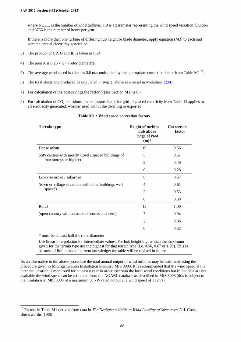
SAP 2012 version 9.92 (October 2013)
88
where Nturbines is the number of wind turbines, 1.9 is a parameter representing the wind speed variation function and 8766 is the number of hours per year. If there is more than one turbine of differing hub height or blade diameter, apply equation (M3) to each and sum the annual electricity generation.
3) The product of CP, G and IE is taken as 0.24.
4) The area A is 0.25 × π × (rotor diameter)².
5) The average wind speed is taken as 5.0 m/s multiplied by the appropriate correction factor from Table M1 18.
6) The total electricity produced as calculated in step 2) above is entered in worksheet (234).
7) For calculation of the cost savings the factor β (see Section M1) is 0.7.
8) For calculation of CO2 emissions, the emissions factor for grid-displaced electricity from Table 12 applies to all electricity generated, whether used within the dwelling or exported.
Table M1 : Wind speed correction factors
Terrain type Height of turbine hub above
ridge of roof (m)*
Correction factor
10 0.56
5 0.51
2 0.40
Dense urban
(city centres with mostly closely spaced buildings of four storeys or higher)
0 0.28
6 0.67
4 0.61
2 0.53
Low rise urban / suburban
(town or village situations with other buildings well spaced)
0 0.39
12 1.00
7 0.94
2 0.86
Rural
(open country with occasional houses and trees)
0 0.82
* must be at least half the rotor diameter Use linear interpolation for intermediate values. For hub height higher than the maximum given for the terrain type use the highest for that terrain type (i.e. 0.56, 0.67 or 1.00). This is because of limitations of current knowledge; the table will be revised in future.
As an alternative to the above procedure the total annual output of wind turbines may be estimated using the procedure given in Microgeneration Installation Standard MIS 3003. It is recommended that the wind speed at the intended location is monitored for at least a year in order ascertain the local wind conditions but if that data are not available the wind speed can be estimated from the NOABL database as described in MIS 3003 (this is subject to the limitation in MIS 3003 of a maximum 50 kW rated output at a wind speed of 11 m/s).
18 Factors in Table M1 derived from data in The Designer's Guide to Wind Loading of Structures, N.J. Cook, Butterworths, 1986
SAP 2012 version 9.92 (October 2013)
89
M3 Wind turbines associated with more than one dwelling This refers to wind turbines such as might be installed as part of a housing development. They are not included for the assessment of ratings but can be included in the assessment of an overall CO2 emission figure inclusive of all energy uses (including appliances and cooking), see Section 16. If not actually on the site they can be included provided that they are connected directly to the site. Electricity surplus to the instantaneous electricity demand of the dwellings is fed into the electricity grid. The total annual output of wind turbines should be estimated using the procedure given in Microgeneration Installation Standard MIS 3003. It is recommended that the wind speed at the intended location is monitored for at least a year in order ascertain the local wind conditions but if those data are not available the wind speed can be estimated from the NOABL database as described in MIS 3003 (this is subject to the limitation in MIS 3003 of a maximum 50 kW rated output at a wind speed of 11 m/s). The total output from the wind turbines should be apportioned between the dwellings concerned on the basis of their floor area, by multiplying the total annual output by the floor area of the dwelling divided by the total floor area of buildings on the development, and entered in kWh/m² into (ZC6) in Section 16.
M4 Small-scale hydro-electric generators Hydro-electric generation is possible only in a small number of situations. Each case is different and detailed calculations of the electricity generated are outside the scope of SAP 2009. Where small-scale hydro-electric generation is applicable, it may be allowed for in SAP calculations as follows. 1) The total electricity generated per year is calculated and signed off by a suitably qualified engineer having
adequate competence in the assessment of the technology. In case of doubt guidance should be sought from BRE.
2) Where more than one dwelling benefits from the hydro-electric generation, the kWh per year attributable to each dwelling is obtained from the total in step 1) by multiplying the total annual output by the floor area of the dwelling divided by the total floor area of buildings on the development.
3) For calculation of the cost savings the factor β (see Section M1) is 0.4.
4) For calculation of CO2 emissions, the emissions factor for grid-displaced electricity from Table 12 applies to all electricity generated, whether used within the dwelling or exported.
5) Where the electricity generator is within the curtilage of the building, and its output is directly connected to the building’s electricity supply, the output is entered in worksheet (236a).
6) In other cases the electricity generated divided by the sum of the floor areas of the buildings concerned may be entered in (ZC6), see Section 16, when the total net CO2 emissions are being calculated.
SAP 2012 version 9.92 (October 2013)
90
Appendix N: Micro-cogeneration (or micro-CHP) and heat pumps
N1 Overview This appendix deals with heating products whose energy performance is supported by test data in the Product Characteristics database and depends critically on the plant size ratio19. Micro-cogeneration (also known as micro-CHP) and heat pumps are two such products. Products can provide a) heating and hot water throughout the year, b) heating and hot water during the heating season only, c) heating only, or d) hot water only. For heat pumps that are not supported by test data see section 9.2.7.
N1.1 Micro-cogeneration Micro-cogeneration provides both heat and electricity. It is assumed to be heat-led, meaning that it is allowed to operate only when there is a demand for space heating or hot water. The domestic application of micro-cogeneration is treated as an alternative to a conventional domestic boiler, using mains gas, LPG, oil or solid fuel. It is also assumed that it is connected to the public electricity supply in such a way that all surplus generated electricity is exported. This appendix is not applicable unless these assumptions have been confirmed. The characteristics of micro-cogeneration are described by data derived from laboratory tests. The test data are used to calculate parameters related to the annual energy performance of the micro-cogeneration “package”. The term “package” refers to a micro-cogeneration unit (such as an engine and generator) in conjunction with a defined set of optional other components (e.g. a boiler or thermal store). The laboratory test data are analysed by an annual performance method to produce results (known as “intermediate results”) that are used for SAP as described in section N2. Any space heating requirements not met by the micro-cogeneration package is to be provided by secondary heating. If a secondary heating system is not specified assume direct electric heaters. If the package provides domestic hot water it is assumed to provide all water heating needs for the applicable period. The heat produced by the package and the electrical energy consumed/generated are based on operation during an average year, taking account of its output rating and the design heat loss for the dwelling in which it is installed. The amount of auxiliary heating is determined by the plant size ratio (full output power of the micro-cogeneration package divided by the design heat loss). If the plant size ratio is less than 0.2 then the package cannot be regarded as a main heating system, and the performance data are invalid for SAP. The electricity consumed/generated will normally be negative, and then represents the net electricity produced by the micro-cogeneration package that is available to offset electricity that would otherwise be taken from the public electricity supply grid or, to the extent that instantaneous generation exceeds instantaneous electricity demand, is exported to the grid. The thermal efficiency of the micro-cogeneration package is used in the normal way for the calculation of energy requirements for space heating and/or water heating (depending on the services provided by the package). The electricity consumed (or the net electricity generation) is scaled according to the net energy use as obtained in the SAP calculation.
N1.2 Heat pumps Heat pumps provide space and/or water heating with efficiencies in excess of 100% as they transfer heat from outside the heated envelope of the dwelling, usually from (a) the ground, (b) ground or surface water, (c) outside air, (d) exhaust air from mechanical extract ventilation (MEV), (d) exhaust air from balanced mechanical ventilation without or with heat recovery (MVHR) or (e) a mixture of exhaust air from an MEV and outside air. A heat pump “package” refers to a heat pump unit in conjunction with a defined set of optional other components (e.g. a thermal store or auxiliary heater). Heat pump packages have been categorised by hot water provision, which can be: - integral hot water store; or - separate cylinder with characteristics specified as part of the package; or - separate cylinder with characteristics not specified as part of the package; or - not provided by heat pump package. In the latter case a water heating system is specified separately for the SAP calculation.
19 Plant size ratio is the full output power of the heating appliance divided by the design heat loss of the dwelling
SAP 2012 version 9.92 (October 2013)
91
The characteristics of heat pump packages are described by data derived from laboratory tests. The laboratory test data are analysed by an annual performance method to produce results (known as “intermediate results”) that are used for SAP as described in N2. An exhaust air heat pump is tested with a given mechanical ventilation system, and so the exhaust air heat pump system is defined as the mechanical ventilation system and the heat pump. The performance of the heat pump package depends on temperature conditions and running hours, which are affected by output rating and the design heat loss of the dwelling. Any space heating requirements not met by the heat pump package is to be provided by secondary heating. If a secondary heating system is not specified assume direct electric heaters. If the package provides domestic hot water it is assumed to provide all water heating needs for the applicable period (any water heating needs not provided by the heat pump is assumed to be met by an electric immersion heater within the package and is explicitly accounted for in the water heating efficiency in the database record for the heat pump). The thermal efficiency of the heat pump package is used in the normal way for the calculation of energy requirements for space heating and/or water heating (depending on the services provided by the package). This appendix covers heat pumps powered solely from electricity (referred to as electric heat pumps) or from fuels including but not limited to mains gas, LPG or oil. N1.2.1 Calculation assumptions
Heat pumps that provide domestic hot water may have synchronised control for water heating. Synchronised control means that the primary operation of the auxiliary water heater (electric immersion) is controlled by the heat pump, so as to ensure that the timing of auxiliary heating is coordinated with the heat pump to prevent unnecessary operation of the auxiliary heater (i.e. the heat pump does as much of the water heating as possible). Local occupant control to provide boost may be present, but this automatically resets once the required hot water temperature is achieved in the cylinder so that further manual intervention is required for any subsequent boost; no allowance is made in this Appendix for boost operation. If a heat pump providing domestic hot water does not have synchronised control, it is assumed that the heat pump operates as an electric immersion, with a Seasonal Performance Factor of 1.0 recorded in the database for hot water service. The heat pump is able to provide all the heat needed for space heating if the plant size ratio (see N2) is large enough. Where that is not the case, the procedure calculates the additional (auxiliary) heat needed on the basis that it is also synchronised and under control of the heat pump, for example via an integral direct-acting electric heater. If such synchronisation is not present or not closely controlled the fuel requirement is liable to be higher than that indicated by following this appendix.
N2 Datasets The data to be used for SAP calculations are provided by way of the Product Characteristics Database. Each database record consists of the data in Table N1 and a number of sets of intermediate test results (Table N2). The intermediate results from the annual energy performance methods for micro-cogeneration and heat pumps are produced in sets, of which a sub-set of parameters depends on the plant size ratio (PSR). Each sub-set is calculated for a different PSR, for example 0.2, 0.5, 1.0, 1.5, 4.0 and 10.0. The plant size ratio (PSR) for the dwelling is calculated as the maximum nominal output of the package divided by the design heat loss of the dwelling taken as the annual average heat loss coefficient, worksheet (39), multiplied by a temperature difference of 24.2 K. In the case of a range-rated package, the PSR for the dwelling is calculated assuming that it is set to the top of the range as this is how it was tested. The intermediate PSR-dependent results applicable to the dwelling are then obtained by linear interpolation20 between the two datasets whose PSRs enclose that of the actual dwelling. The dwelling-specific values are used in equations (N1) to (N14) to calculate the parameters used in the SAP calculation. If the PSR for the dwelling is greater than the largest value in the database record or less than the smallest value in the database record the data are invalid for the dwelling concerned. However in the case of a heat pump (ground, water or air source) where the PSR is greater than the largest value in the data record, an efficiency may be used obtained from linear interpolation20 between that at the largest PSR in the data record and efficiency 100% at PSR four times the largest PSR in the data record21. This extension to higher PSRs is not valid for exhaust air heat pumps. 20 For the efficiency values, the interpolated efficiency is the reciprocal of linear interpolation between the reciprocals of the efficiencies. 21 For a non-electric heat pump use the specific electricity value for the largest PSR in the data record.
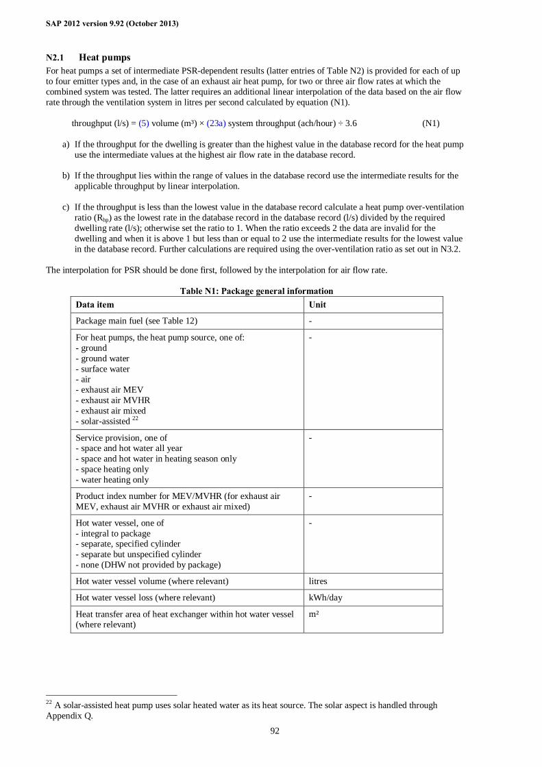
SAP 2012 version 9.92 (October 2013)
92
N2.1 Heat pumps For heat pumps a set of intermediate PSR-dependent results (latter entries of Table N2) is provided for each of up to four emitter types and, in the case of an exhaust air heat pump, for two or three air flow rates at which the combined system was tested. The latter requires an additional linear interpolation of the data based on the air flow rate through the ventilation system in litres per second calculated by equation (N1). throughput (l/s) = (5) volume (m³) × (23a) system throughput (ach/hour) ÷ 3.6 (N1)
a) If the throughput for the dwelling is greater than the highest value in the database record for the heat pump use the intermediate values at the highest air flow rate in the database record.
b) If the throughput lies within the range of values in the database record use the intermediate results for the
applicable throughput by linear interpolation. c) If the throughput is less than the lowest value in the database record calculate a heat pump over-ventilation
ratio (Rhp) as the lowest rate in the database record in the database record (l/s) divided by the required dwelling rate (l/s); otherwise set the ratio to 1. When the ratio exceeds 2 the data are invalid for the dwelling and when it is above 1 but less than or equal to 2 use the intermediate results for the lowest value in the database record. Further calculations are required using the over-ventilation ratio as set out in N3.2.
The interpolation for PSR should be done first, followed by the interpolation for air flow rate.
Table N1: Package general information Data item Unit
Package main fuel (see Table 12) -
For heat pumps, the heat pump source, one of: - ground - ground water - surface water - air - exhaust air MEV - exhaust air MVHR - exhaust air mixed - solar-assisted 22
-
Service provision, one of - space and hot water all year - space and hot water in heating season only - space heating only - water heating only
-
Product index number for MEV/MVHR (for exhaust air MEV, exhaust air MVHR or exhaust air mixed)
-
Hot water vessel, one of - integral to package - separate, specified cylinder - separate but unspecified cylinder - none (DHW not provided by package)
-
Hot water vessel volume (where relevant) litres
Hot water vessel loss (where relevant) kWh/day
Heat transfer area of heat exchanger within hot water vessel (where relevant)
m²
22 A solar-assisted heat pump uses solar heated water as its heat source. The solar aspect is handled through Appendix Q.
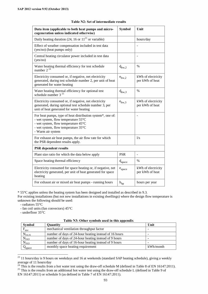
SAP 2012 version 9.92 (October 2013)
93
Table N2: Set of intermediate results
Data item (applicable to both heat pumps and micro-cogeneration unless indicated otherwise)
Symbol Unit
Daily heating duration (24, 16 or 1123 or variable) hours/day
Effect of weather compensation included in test data (yes/no) (heat pumps only)
-
Central heating circulator power included in test data (yes/no)
-
Water heating thermal efficiency for test schedule number 2 24
ηhw,2 %
Electricity consumed or, if negative, net electricity generated, during test schedule number 2, per unit of heat generated for water heating
ehw,2 kWh of electricity per kWh of heat
Water heating thermal efficiency for optional test schedule number 3 25
ηhw,3 %
Electricity consumed or, if negative, net electricity generated, during optional test schedule number 3, per unit of heat generated for water heating
ehw,3 kWh of electricity per kWh of heat
For heat pumps, type of heat distribution system*, one of: - wet system, flow temperature 55°C - wet system, flow temperature 45°C - wet system, flow temperature 35°C - Warm air system
-
For exhaust air heat pumps, the air flow rate for which the PSR dependent results apply.
l/s
PSR dependent results
Plant size ratio for which the data below apply PSR -
Space heating thermal efficiency ηspace %
Electricity consumed for space heating or, if negative, net electricity generated, per unit of heat generated for space heating
espace kWh of electricity per kWh of heat
For exhaust air or mixed air heat pumps - running hours hhp hours per year
* 55°C applies unless the heating system has been designed and installed as described in 9.3. For existing installations (but not new installations in existing dwellings) where the design flow temperature is unknown the following should be used: - radiators 55°C - fan coil units (fan convectors) 45°C - underfloor 35°C
Table N3: Other symbols used in this appendix Symbol Quantity Unit Fmv mechanical ventilation throughput factor - N24,16 number of days of 24-hour heating instead of 16 hours - N24,9 number of days of 24-hour heating instead of 9 hours - N16,9 number of days of 16-hour heating instead of 9 hours - Qspace monthly space heating requirement kWh/month
23 11 hours/day is 9 hours on weekdays and 16 at weekends (standard SAP heating schedule), giving a weekly average of 11 hours/day 24 This is the results from a hot water test using the draw-off schedule M (defined in Table 8 of EN 16147:2011). 25 This is the results from an additional hot water test using the draw-off schedule L (defined in Table 9 of EN 16147:2011) or schedule S (as defined in Table 7 of EN 16147:2011).
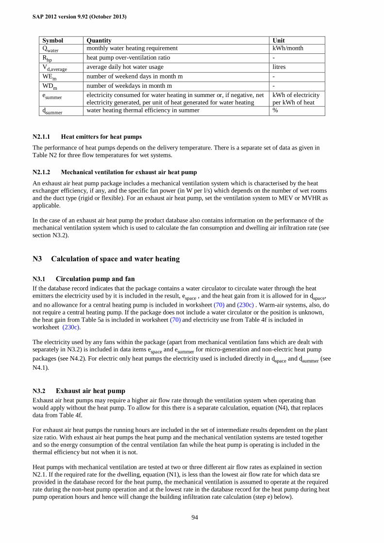
SAP 2012 version 9.92 (October 2013)
94
Symbol Quantity Unit Qwater monthly water heating requirement kWh/month Rhp heat pump over-ventilation ratio - Vd,average average daily hot water usage litres WEm number of weekend days in month m - WDm number of weekdays in month m - esummer electricity consumed for water heating in summer or, if negative, net
electricity generated, per unit of heat generated for water heating kWh of electricity per kWh of heat
ηsummer water heating thermal efficiency in summer % N2.1.1 Heat emitters for heat pumps
The performance of heat pumps depends on the delivery temperature. There is a separate set of data as given in Table N2 for three flow temperatures for wet systems. N2.1.2 Mechanical ventilation for exhaust air heat pump
An exhaust air heat pump package includes a mechanical ventilation system which is characterised by the heat exchanger efficiency, if any, and the specific fan power (in W per l/s) which depends on the number of wet rooms and the duct type (rigid or flexible). For an exhaust air heat pump, set the ventilation system to MEV or MVHR as applicable. In the case of an exhaust air heat pump the product database also contains information on the performance of the mechanical ventilation system which is used to calculate the fan consumption and dwelling air infiltration rate (see section N3.2).
N3 Calculation of space and water heating
N3.1 Circulation pump and fan If the database record indicates that the package contains a water circulator to circulate water through the heat emitters the electricity used by it is included in the result, espace , and the heat gain from it is allowed for in ηspace, and no allowance for a central heating pump is included in worksheet (70) and (230c) . Warm-air systems, also, do not require a central heating pump. If the package does not include a water circulator or the position is unknown, the heat gain from Table 5a is included in worksheet (70) and electricity use from Table 4f is included in worksheet (230c). The electricity used by any fans within the package (apart from mechanical ventilation fans which are dealt with separately in N3.2) is included in data items espace and esummer for micro-generation and non-electric heat pump packages (see N4.2). For electric only heat pumps the electricity used is included directly in ηspace and ηsummer (see N4.1).
N3.2 Exhaust air heat pump Exhaust air heat pumps may require a higher air flow rate through the ventilation system when operating than would apply without the heat pump. To allow for this there is a separate calculation, equation (N4), that replaces data from Table 4f. For exhaust air heat pumps the running hours are included in the set of intermediate results dependent on the plant size ratio. With exhaust air heat pumps the heat pump and the mechanical ventilation systems are tested together and so the energy consumption of the central ventilation fan while the heat pump is operating is included in the thermal efficiency but not when it is not. Heat pumps with mechanical ventilation are tested at two or three different air flow rates as explained in section N2.1. If the required rate for the dwelling, equation (N1), is less than the lowest air flow rate for which data sre provided in the database record for the heat pump, the mechanical ventilation is assumed to operate at the required rate during the non-heat pump operation and at the lowest rate in the database record for the heat pump during heat pump operation hours and hence will change the building infiltration rate calculation (step e) below).
SAP 2012 version 9.92 (October 2013)
95
a) Obtain from the heat pump record the run hours (hhp) applicable to the system exhaust air throughput for the dwelling, after applying linear interpolation based on the plant size ratio and system air throughput, rounding hhp to the nearest integer value. Run hours are the total number of hours per year that the heat pump operates to achieve that heat output required by the building.
b) Obtain from the MEV/MVHR database record the specific fan power (SFP) for the duct type and number
of wet rooms. If data are not listed for the duct type or number of wet rooms use the default values in Table 4g.
c) Calculate the heat pump over-ventilation ratio Rhp using equation (N2). This is the ratio of the air flow
through the ventilation system allowing for the operational requirement of the heat pump, to that which would apply for an equivalent ventilation system without a heat pump.
If the lowest air flow rate in the heat pump database record (in l/s) is less than the throughput for the dwelling from equation (N1), Rhp = 1; otherwise: Rhp = lowest air flow rate (l/s) × 3.6 ÷ [ (23a) × (5)] (N2)
d) Calculate the annual fan consumption according to equation (N3) in kWh per year:
(230a) = (5) × SFP × Fan in-use factor × (23a) × Rhp × (8760 – hhp) ÷ 3600 (N3)
e) Obtain the mechanical ventilation throughput factor, Fmv, from equation (N4) for calculation of
worksheet (23b):
Fmv = [(8760 – hhp) + (Rhp × hhp)] ÷ 8760 (N4) Note. The above is not implemented as an iterative procedure. Instead: - set Fmv = 1 and calculate the ventilation loss rate and PSR - obtain Fmv from equation (N4) - re-calculate the ventilation loss rate and PSR, and apply this Appendix without further change to Fmv or Rhp.
N3.3 Mean internal temperature The package, when undersized in relation to the design heat loss of the dwelling, can provide space heating needs on more days of the heating season if it operates for 16 hours per day or continuously. Table N4 shows the days of operation indicated by the parameters N24,16, N24,9 and N16,9 depending on the heating duration defined in the database record and, if duration is variable, on the plant size ratio. For the normal SAP heating schedule, the heating season would comprise 68 weekend days with 16 hours of heating and 170 weekdays with 9 hours of heating (2 hours in the morning and 7 hours in the evening). Summer months are included here only for consideration of cooling (see Table 10b). Obtain the total number of days per year for each mode of operation from Tables N4 and N5. Allocate these to months in the following order: Jan, Dec, Feb, Mar, Nov, Apr, Oct, May (coldest to the warmest), until all the days N24,16, N24,9 and N16,9 have been allocated. All the days N24,9 are allocated first, and then N16,9.
Example. Variable heating duration with PSR = 0.2 (first row of Table N5 applies: N24,9 = 143, N16,9 = 8 and N24,16 = 57). January: N24,16.m=1 = 9 and N24,9.m=1 = 22. All weekdays in January have been allocated so N16,9,m=1 = 0. The number of days remaining to be allocated is now N24,16 = 48, N24,9 = 121 and N16,9 = 8. This is continued for Dec, Feb, Mar, Nov, Apr after which the number of days remaining to be allocated is N24,16 = 6, N24,9 = 13 and N16,9 = 8. For October, N24,16.m=10 = 6, N24,9.m=10 = 13 and N16,9,,m=10 = 8. All days are now allocated so there are none for May.
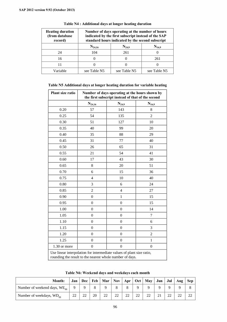
SAP 2012 version 9.92 (October 2013)
96
Table N4 : Additional days at longer heating duration
Heating duration (from database
record)
Number of days operating at the number of hours indicated by the first subscript instead of the SAP standard hours indicated by the second subscript
N24,16 N24,9 N16,9 24 104 261 0 16 0 0 261 11 0 0 0
Variable see Table N5 see Table N5 see Table N5
Table N5 Additional days at longer heating duration for variable heating
Plant size ratio Number of days operating at the hours shown by the first subscript instead of that of the second
N24,16 N24,9 N16,9 0.20 57 143 8 0.25 54 135 2 0.30 51 127 10 0.35 40 99 20 0.40 35 88 29 0.45 31 77 40 0.50 26 65 31 0.55 21 54 41 0.60 17 43 30 0.65 8 20 51 0.70 6 15 36 0.75 4 10 40 0.80 3 6 24 0.85 2 4 27 0.90 0 1 15 0.95 0 0 15 1.00 0 0 14 1.05 0 0 7 1.10 0 0 6 1.15 0 0 3 1.20 0 0 2 1.25 0 0 1
1.30 or more 0 0 0 Use linear interpolation for intermediate values of plant size ratio, rounding the result to the nearest whole number of days.
Table N6: Weekend days and weekdays each month
Month: Jan Dec Feb Mar Nov Apr Oct May Jun Jul Aug Sep
Number of weekend days, WEm 9 9 8 9 8 8 9 9 9 9 9 8
Number of weekdays, WDm 22 22 20 22 22 22 22 22 21 22 22 22
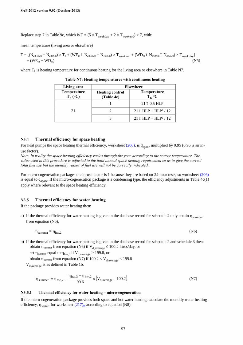
SAP 2012 version 9.92 (October 2013)
97
Replace step 7 in Table 9c, which is T = (5 × Tweekday + 2 × Tweekend) ÷ 7, with: mean temperature (living area or elsewhere) T = [(N24,16,m + N24,9,m) × Th + (WEm – N24,16,m + N16,9,m) × Tweekend + (WDm – N16,9,m – N24,9,m) × Tweekday] ÷ (WEm + WDm) (N5) where Th is heating temperature for continuous heating for the living area or elsewhere in Table N7.
Table N7: Heating temperatures with continuous heating
Living area Elsewhere Temperature
Th (°C) Heating control
(Table 4e) Temperature
Th °C
1 21 – 0.5 HLP
2 21 – HLP + HLP² / 12 21
3 21 – HLP + HLP² / 12
N3.4 Thermal efficiency for space heating For heat pumps the space heating thermal efficiency, worksheet (206), is ηspace multiplied by 0.95 (0.95 is an in-use factor). Note. In reality the space heating efficiency varies through the year according to the source temperature. The value used in this procedure is adjusted to the total annual space heating requirement so as to give the correct total fuel use but the monthly values of fuel use will not be correctly indicated. For micro-cogeneration packages the in-use factor is 1 because they are based on 24-hour tests, so worksheet (206) is equal to ηspace. If the micro-cogeneration package is a condensing type, the efficiency adjustments in Table 4c(1) apply where relevant to the space heating efficiency.
N3.5 Thermal efficiency for water heating If the package provides water heating then: a) If the thermal efficiency for water heating is given in the database record for schedule 2 only obtain ηsummer
from equation (N6).
ηsummer = ηhw,2 (N6) b) If the thermal efficiency for water heating is given in the database record for schedule 2 and schedule 3 then:
obtain ηsummer from equation (N6) if Vd,average ≤ 100.2 litres/day, or set ηsummer equal to ηhw,3 if Vd,average ≥ 199.8, or obtain ηsummer from equation (N7) if 100.2 < Vd,average < 199.8
Vd,average is as defined in Table 1b.
( )2.100V6.99 average,d
2,hw3,hw2,hwsummer −×
η−η+η=η (N7)
N3.5.1 Thermal efficiency for water heating – micro-cogeneration
If the micro-cogeneration package provides both space and hot water heating, calculate the monthly water heating efficiency, ηwater, for worksheet (217)m according to equation (N8).
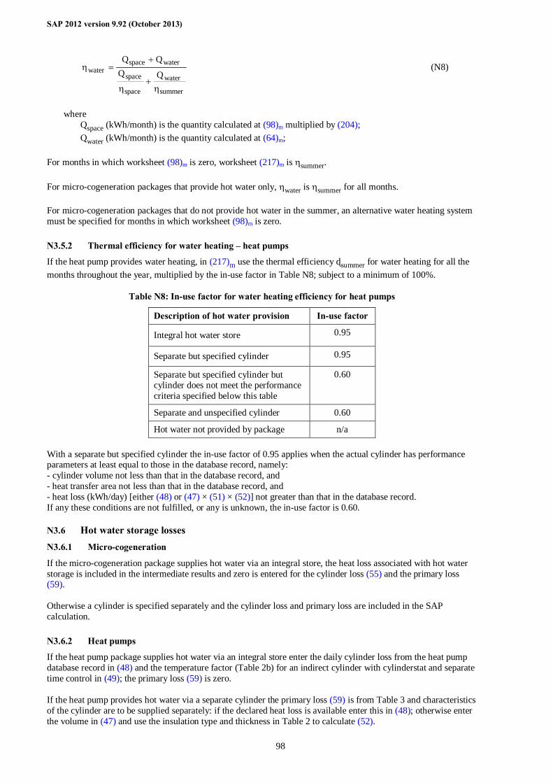
SAP 2012 version 9.92 (October 2013)
98
summer
water
space
space
waterspacewater QQ
η+
η
+=η (N8)
where
Qspace (kWh/month) is the quantity calculated at (98)m multiplied by (204); Qwater (kWh/month) is the quantity calculated at (64)m;
For months in which worksheet (98)m is zero, worksheet (217)m is ηsummer. For micro-cogeneration packages that provide hot water only, ηwater is ηsummer for all months. For micro-cogeneration packages that do not provide hot water in the summer, an alternative water heating system must be specified for months in which worksheet (98)m is zero. N3.5.2 Thermal efficiency for water heating – heat pumps
If the heat pump provides water heating, in (217)m use the thermal efficiency ηsummer for water heating for all the months throughout the year, multiplied by the in-use factor in Table N8; subject to a minimum of 100%.
Table N8: In-use factor for water heating efficiency for heat pumps
Description of hot water provision In-use factor
Integral hot water store 0.95
Separate but specified cylinder 0.95
Separate but specified cylinder but cylinder does not meet the performance criteria specified below this table
0.60
Separate and unspecified cylinder 0.60
Hot water not provided by package n/a With a separate but specified cylinder the in-use factor of 0.95 applies when the actual cylinder has performance parameters at least equal to those in the database record, namely: - cylinder volume not less than that in the database record, and - heat transfer area not less than that in the database record, and - heat loss (kWh/day) [either (48) or (47) × (51) × (52)] not greater than that in the database record. If any these conditions are not fulfilled, or any is unknown, the in-use factor is 0.60.
N3.6 Hot water storage losses N3.6.1 Micro-cogeneration
If the micro-cogeneration package supplies hot water via an integral store, the heat loss associated with hot water storage is included in the intermediate results and zero is entered for the cylinder loss (55) and the primary loss (59). Otherwise a cylinder is specified separately and the cylinder loss and primary loss are included in the SAP calculation. N3.6.2 Heat pumps
If the heat pump package supplies hot water via an integral store enter the daily cylinder loss from the heat pump database record in (48) and the temperature factor (Table 2b) for an indirect cylinder with cylinderstat and separate time control in (49); the primary loss (59) is zero. If the heat pump provides hot water via a separate cylinder the primary loss (59) is from Table 3 and characteristics of the cylinder are to be supplied separately: if the declared heat loss is available enter this in (48); otherwise enter the volume in (47) and use the insulation type and thickness in Table 2 to calculate (52).
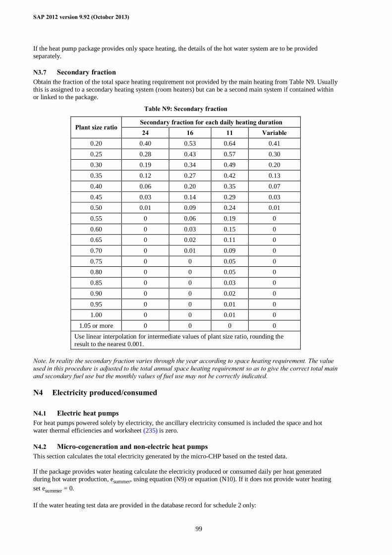
SAP 2012 version 9.92 (October 2013)
99
If the heat pump package provides only space heating, the details of the hot water system are to be provided separately.
N3.7 Secondary fraction Obtain the fraction of the total space heating requirement not provided by the main heating from Table N9. Usually this is assigned to a secondary heating system (room heaters) but can be a second main system if contained within or linked to the package.
Table N9: Secondary fraction
Secondary fraction for each daily heating duration Plant size ratio
24 16 11 Variable 0.20 0.40 0.53 0.64 0.41 0.25 0.28 0.43 0.57 0.30 0.30 0.19 0.34 0.49 0.20 0.35 0.12 0.27 0.42 0.13 0.40 0.06 0.20 0.35 0.07 0.45 0.03 0.14 0.29 0.03 0.50 0.01 0.09 0.24 0.01 0.55 0 0.06 0.19 0 0.60 0 0.03 0.15 0 0.65 0 0.02 0.11 0 0.70 0 0.01 0.09 0 0.75 0 0 0.05 0 0.80 0 0 0.05 0 0.85 0 0 0.03 0 0.90 0 0 0.02 0 0.95 0 0 0.01 0 1.00 0 0 0.01 0
1.05 or more 0 0 0 0 Use linear interpolation for intermediate values of plant size ratio, rounding the result to the nearest 0.001.
Note. In reality the secondary fraction varies through the year according to space heating requirement. The value used in this procedure is adjusted to the total annual space heating requirement so as to give the correct total main and secondary fuel use but the monthly values of fuel use may not be correctly indicated.
N4 Electricity produced/consumed
N4.1 Electric heat pumps For heat pumps powered solely by electricity, the ancillary electricity consumed is included the space and hot water thermal efficiencies and worksheet (235) is zero.
N4.2 Micro-cogeneration and non-electric heat pumps This section calculates the total electricity generated by the micro-CHP based on the tested data. If the package provides water heating calculate the electricity produced or consumed daily per heat generated during hot water production, esummer, using equation (N9) or equation (N10). If it does not provide water heating set esummer = 0. If the water heating test data are provided in the database record for schedule 2 only:
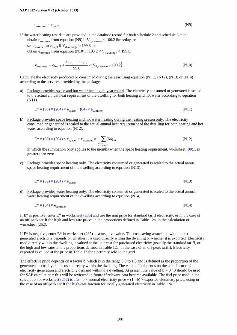
SAP 2012 version 9.92 (October 2013)
100
esummer = ehw,2 (N9) If the water heating test data are provided in the database record for both schedule 2 and schedule 3 then:
obtain esummer from equation (N9) if Vd,average ≤ 100.2 litres/day, or set esummer to ehw,3 if Vd,average ≥ 199.8, or obtain esummer from equation (N10) if 100.2 < Vd,average < 199.8.
( )2.100V6.99ee
ee average,d2,hw3,hw
2,hwsummer −×−
+= (N10)
Calculate the electricity produced or consumed during the year using equation (N11), (N12), (N13) or (N14) according to the services provided by the package. a) Package provides space and hot water heating all year round. The electricity consumed or generated is scaled
to the actual annual heat requirement of the dwelling for both heating and hot water according to equation (N11).
E* = (98) × (204) × espace + (64) × esummer (N11)
b) Package provides space heating and hot water heating during the heating season only. The electricity
consumed or generated is scaled to the actual annual heat requirement of the dwelling for both heating and hot water according to equation (N12).
E* = (98) × (204) × espace + esummer × ∑
>0)98(m
m
)64( (N12)
in which the summation only applies to the months when the space heating requirement, worksheet (98)m, is greater than zero.
c) Package provides space heating only. The electricity consumed or generated is scaled to the actual annual
space heating requirement of the dwelling according to equation (N13).
E* = (98) × (204) × espace (N13) d) Package provides water heating only. The electricity consumed or generated is scaled to the actual annual
water heating requirement of the dwelling according to equation (N14).
E* = (64) × esummer (N14) If E* is positive, enter E* in worksheet (235) and use the unit price for standard tariff electricity, or in the case of an off-peak tariff the high and low rate prices in the proportions defined in Table 12a, in the calculation of worksheet (252). If E* is negative, enter E* in worksheet (235) as a negative value. The cost saving associated with the net generated electricity depends on whether it is used directly within the dwelling or whether it is exported. Electricity used directly within the dwelling is valued at the unit cost for purchased electricity (usually the standard tariff, or the high and low rates in the proportions defined in Table 12a, in the case of an off-peak tariff). Electricity exported is valued at the price in Table 12 for electricity sold to the grid. The effective price depends on a factor β, which is in the range 0.0 to 1.0 and is defined as the proportion of the generated electricity that is used directly within the dwelling. The value of β depends on the coincidence of electricity generation and electricity demand within the dwelling. At present the value of β = 0.40 should be used for SAP calculations: this will be reviewed in future if relevant data become available. The fuel price used in the calculation of worksheet (252) is then: β × normal electricity price + (1 - β) × exported electricity price, using in the case of an off-peak tariff the high-rate fraction for locally generated electricity in Table 12a.

SAP 2012 version 9.92 (October 2013)
101
Appendix O (not used)
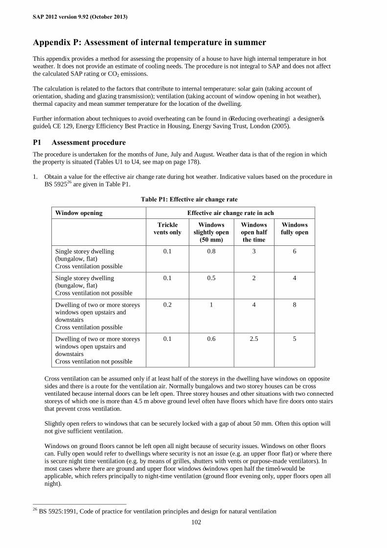
SAP 2012 version 9.92 (October 2013)
102
Appendix P: Assessment of internal temperature in summer
This appendix provides a method for assessing the propensity of a house to have high internal temperature in hot weather. It does not provide an estimate of cooling needs. The procedure is not integral to SAP and does not affect the calculated SAP rating or CO2 emissions. The calculation is related to the factors that contribute to internal temperature: solar gain (taking account of orientation, shading and glazing transmission); ventilation (taking account of window opening in hot weather), thermal capacity and mean summer temperature for the location of the dwelling. Further information about techniques to avoid overheating can be found in ‘Reducing overheating– a designer’s guide’, CE 129, Energy Efficiency Best Practice in Housing, Energy Saving Trust, London (2005).
P1 Assessment procedure The procedure is undertaken for the months of June, July and August. Weather data is that of the region in which the property is situated (Tables U1 to U4, see map on page 178). 1. Obtain a value for the effective air change rate during hot weather. Indicative values based on the procedure in
BS 592526 are given in Table P1.
Table P1: Effective air change rate
Window opening Effective air change rate in ach
Trickle vents only
Windows slightly open
(50 mm)
Windows open half the time
Windows fully open
Single storey dwelling (bungalow, flat) Cross ventilation possible
0.1 0.8 3 6
Single storey dwelling (bungalow, flat) Cross ventilation not possible
0.1 0.5 2 4
Dwelling of two or more storeys windows open upstairs and downstairs Cross ventilation possible
0.2 1 4 8
Dwelling of two or more storeys windows open upstairs and downstairs Cross ventilation not possible
0.1 0.6 2.5 5
Cross ventilation can be assumed only if at least half of the storeys in the dwelling have windows on opposite sides and there is a route for the ventilation air. Normally bungalows and two storey houses can be cross ventilated because internal doors can be left open. Three storey houses and other situations with two connected storeys of which one is more than 4.5 m above ground level often have floors which have fire doors onto stairs that prevent cross ventilation. Slightly open refers to windows that can be securely locked with a gap of about 50 mm. Often this option will not give sufficient ventilation. Windows on ground floors cannot be left open all night because of security issues. Windows on other floors can. Fully open would refer to dwellings where security is not an issue (e.g. an upper floor flat) or where there is secure night time ventilation (e.g. by means of grilles, shutters with vents or purpose-made ventilators). In most cases where there are ground and upper floor windows ‘windows open half the time’ would be applicable, which refers principally to night-time ventilation (ground floor evening only, upper floors open all night).
26 BS 5925:1991, Code of practice for ventilation principles and design for natural ventilation
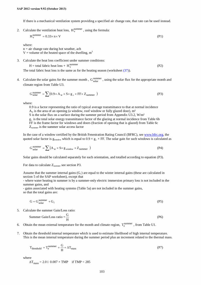
SAP 2012 version 9.92 (October 2013)
103
If there is a mechanical ventilation system providing a specified air change rate, that rate can be used instead. 2. Calculate the ventilation heat loss, summer
vH , using the formula:
Vn33.0Hsummerv ××= (P1)
where: n = air change rate during hot weather, ach V = volume of the heated space of the dwelling, m3
3. Calculate the heat loss coefficient under summer conditions: H = total fabric heat loss + summer
vH (P2) The total fabric heat loss is the same as for the heating season (worksheet (37)).
4. Calculate the solar gains for the summer month , summer
solarG , using the solar flux for the appropriate month and climate region from Table U3.
( )∑ ×××××= ⊥ summerw
summersolar ZFFgSA9.0G (P3)
where: 0.9 is a factor representing the ratio of typical average transmittance to that at normal incidence Aw is the area of an opening (a window, roof window or fully glazed door), m² S is the solar flux on a surface during the summer period from Appendix U3.2, W/m² g⊥ is the total solar energy transmittance factor of the glazing at normal incidence from Table 6b FF is the frame factor for windows and doors (fraction of opening that is glazed) from Table 6c Zsummer is the summer solar access factor In the case of a window certified by the British Fenestration Rating Council (BFRC), see www.bfrc.org, the quoted solar factor is gwindow which is equal to 0.9 × g⊥ × FF. The solar gain for such windows is calculated as
( )∑ ×××= summerwsummersolar ZgSAG window (P4)
Solar gains should be calculated separately for each orientation, and totalled according to equation (P3). For data to calculate Zsummer see section P3.
Assume that the summer internal gains (Gi ) are equal to the winter internal gains (these are calculated in section 5 of the SAP worksheet), except that - where water heating in summer is by a summer-only electric immersion primary loss is not included in the summer gains, and - gains associated with heating systems (Table 5a) are not included in the summer gains, so that the total gains are:
isummersolar GGG += (P5)
5. Calculate the summer Gain/Loss ratio:
Summer Gain/Loss ratio =HG (P6)
6. Obtain the mean external temperature for the month and climate region, summereT , from Table U1.
7. Obtain the threshold internal temperature which is used to estimate likelihood of high internal temperature.
This is the mean internal temperature during the summer period plus an increment related to the thermal mass.
masssummerethreshold T
HGTT ∆++= (P7)
where ∆Tmass = 2.0 – 0.007 × TMP if TMP < 285
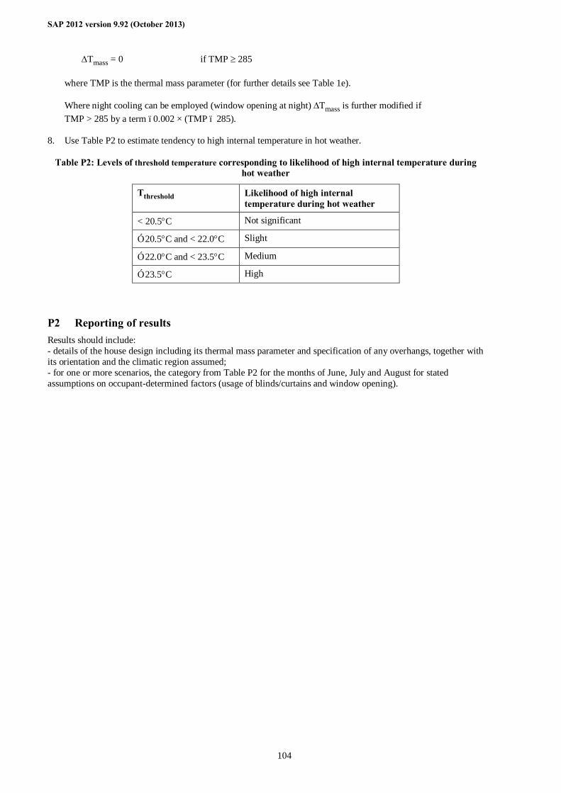
SAP 2012 version 9.92 (October 2013)
104
∆Tmass = 0 if TMP ≥ 285 where TMP is the thermal mass parameter (for further details see Table 1e). Where night cooling can be employed (window opening at night) ∆Tmass is further modified if TMP > 285 by a term –0.002 × (TMP – 285).
8. Use Table P2 to estimate tendency to high internal temperature in hot weather.
Table P2: Levels of threshold temperature corresponding to likelihood of high internal temperature during hot weather
Tthreshold Likelihood of high internal temperature during hot weather
< 20.5°C Not significant
≥ 20.5°C and < 22.0°C Slight
≥ 22.0°C and < 23.5°C Medium
≥ 23.5°C High
P2 Reporting of results Results should include: - details of the house design including its thermal mass parameter and specification of any overhangs, together with its orientation and the climatic region assumed; - for one or more scenarios, the category from Table P2 for the months of June, July and August for stated assumptions on occupant-determined factors (usage of blinds/curtains and window opening).
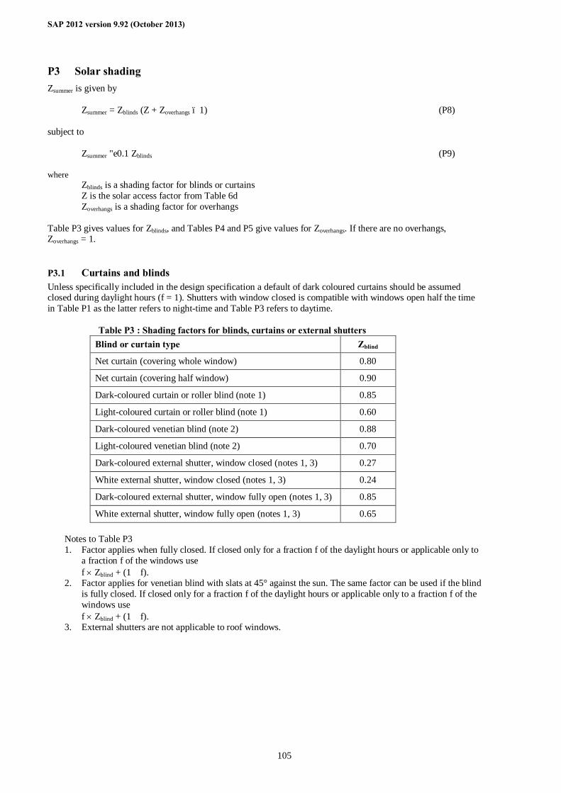
SAP 2012 version 9.92 (October 2013)
105
P3 Solar shading Zsummer is given by
Zsummer = Zblinds (Z + Zoverhangs – 1) (P8) subject to
Zsummer ≥ 0.1 Zblinds (P9)
where Zblinds is a shading factor for blinds or curtains Z is the solar access factor from Table 6d Zoverhangs is a shading factor for overhangs Table P3 gives values for Zblinds, and Tables P4 and P5 give values for Zoverhangs. If there are no overhangs, Zoverhangs = 1.
P3.1 Curtains and blinds Unless specifically included in the design specification a default of dark coloured curtains should be assumed closed during daylight hours (f = 1). Shutters with window closed is compatible with windows open half the time in Table P1 as the latter refers to night-time and Table P3 refers to daytime.
Table P3 : Shading factors for blinds, curtains or external shutters Blind or curtain type Zblind
Net curtain (covering whole window) 0.80
Net curtain (covering half window) 0.90
Dark-coloured curtain or roller blind (note 1) 0.85
Light-coloured curtain or roller blind (note 1) 0.60
Dark-coloured venetian blind (note 2) 0.88
Light-coloured venetian blind (note 2) 0.70
Dark-coloured external shutter, window closed (notes 1, 3) 0.27
White external shutter, window closed (notes 1, 3) 0.24
Dark-coloured external shutter, window fully open (notes 1, 3) 0.85
White external shutter, window fully open (notes 1, 3) 0.65 Notes to Table P3 1. Factor applies when fully closed. If closed only for a fraction f of the daylight hours or applicable only to
a fraction f of the windows use f × Zblind + (1 – f).
2. Factor applies for venetian blind with slats at 45° against the sun. The same factor can be used if the blind is fully closed. If closed only for a fraction f of the daylight hours or applicable only to a fraction f of the windows use f × Zblind + (1 – f).
3. External shutters are not applicable to roof windows.
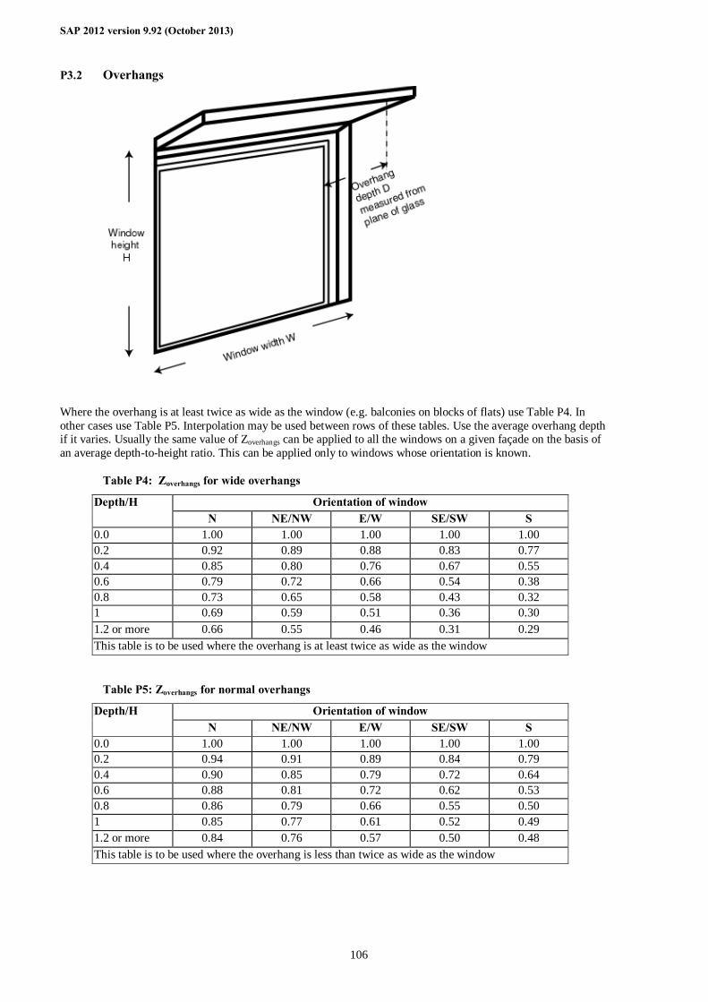
SAP 2012 version 9.92 (October 2013)
106
P3.2 Overhangs
Where the overhang is at least twice as wide as the window (e.g. balconies on blocks of flats) use Table P4. In other cases use Table P5. Interpolation may be used between rows of these tables. Use the average overhang depth if it varies. Usually the same value of Zoverhangs can be applied to all the windows on a given façade on the basis of an average depth-to-height ratio. This can be applied only to windows whose orientation is known.
Table P4: Zoverhangs for wide overhangs
Orientation of window Depth/H N NE/NW E/W SE/SW S
0.0 1.00 1.00 1.00 1.00 1.00 0.2 0.92 0.89 0.88 0.83 0.77 0.4 0.85 0.80 0.76 0.67 0.55 0.6 0.79 0.72 0.66 0.54 0.38 0.8 0.73 0.65 0.58 0.43 0.32 1 0.69 0.59 0.51 0.36 0.30 1.2 or more 0.66 0.55 0.46 0.31 0.29 This table is to be used where the overhang is at least twice as wide as the window
Table P5: Zoverhangs for normal overhangs
Orientation of window Depth/H N NE/NW E/W SE/SW S
0.0 1.00 1.00 1.00 1.00 1.00 0.2 0.94 0.91 0.89 0.84 0.79 0.4 0.90 0.85 0.79 0.72 0.64 0.6 0.88 0.81 0.72 0.62 0.53 0.8 0.86 0.79 0.66 0.55 0.50 1 0.85 0.77 0.61 0.52 0.49 1.2 or more 0.84 0.76 0.57 0.50 0.48 This table is to be used where the overhang is less than twice as wide as the window
SAP 2012 version 9.92 (October 2013)
107
Appendix Q: Special features and specific data
Q1 Special features This appendix provides a method to enable the SAP calculation to make use of the characteristics of technologies that are not included in the published SAP specification. This procedure may only be used for technologies whose characteristics have been independently assessed and which are described on the web page www.ncm-pcdb.org.uk/sap or a web page linked to it. For such systems, this web page will contain details for calculating the data to be used in the SAP calculation. In general the technology might use additional energy from one fuel while saving energy from another fuel. Where more than one technology is applicable the procedure is applied for each. Where the Appendix Q data are provided on an annual basis: SAP rating: 1. include the amount of energy saved by the technology (kWh/year) in worksheet (236n) or (336n); 2. multiply the amount of saved energy by the unit price of the fuel concerned to obtain worksheet (270) or
(380); 3. include the amount of energy used by the technology in worksheet (237n); 4. multiply the energy used by the unit price of the fuel concerned and to obtain worksheet (271) or (371); 5. include both these items in the calculation of the total energy cost. In the case of electricity using an off-peak tariff the fractions of electricity at the high and low rates are needed to determine the appropriate price (Table 12a). CO2 emissions: the amount of energy saved or used by the technology (kWh/year) is multiplied by the appropriate emission factor and included in the total CO2 emissions. In some cases the data may be provided on a monthly basis, in which case they are included at the appropriate point in the worksheet. Where the feature is concerned only with CO2 emissions rather than energy, enter the applicable emissions figures directly into worksheet (270) and (271). For community schemes, specific data may be given in the Products Characteristics Database.
Q2 Specific data A similar mechanism will be used to enable the use of data specific to a technology. For applicable data types, the web page mentioned above will give details of the conditions for accepting the data and their applicability within the SAP calculation.
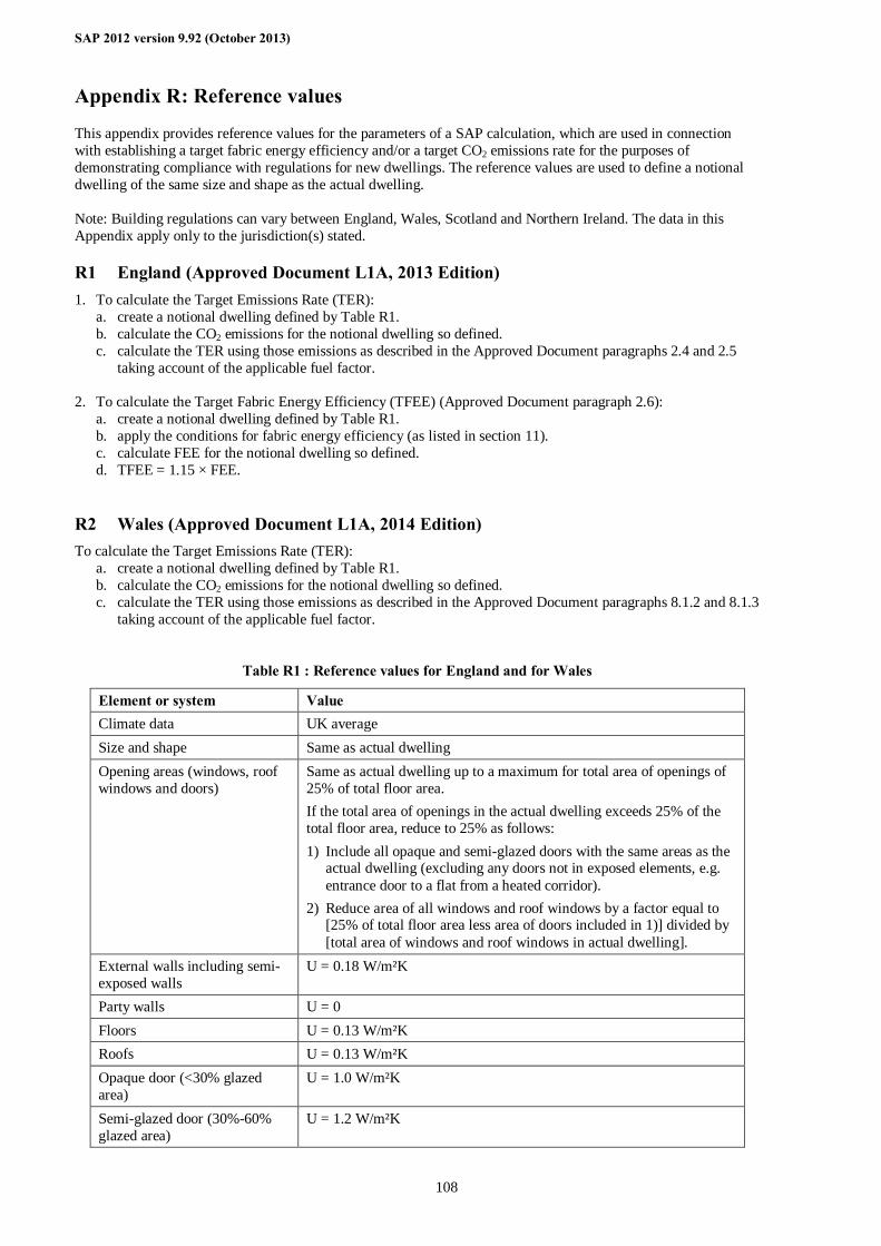
SAP 2012 version 9.92 (October 2013)
108
Appendix R: Reference values
This appendix provides reference values for the parameters of a SAP calculation, which are used in connection with establishing a target fabric energy efficiency and/or a target CO2 emissions rate for the purposes of demonstrating compliance with regulations for new dwellings. The reference values are used to define a notional dwelling of the same size and shape as the actual dwelling. Note: Building regulations can vary between England, Wales, Scotland and Northern Ireland. The data in this Appendix apply only to the jurisdiction(s) stated.
R1 England (Approved Document L1A, 2013 Edition) 1. To calculate the Target Emissions Rate (TER):
a. create a notional dwelling defined by Table R1. b. calculate the CO2 emissions for the notional dwelling so defined. c. calculate the TER using those emissions as described in the Approved Document paragraphs 2.4 and 2.5
taking account of the applicable fuel factor. 2. To calculate the Target Fabric Energy Efficiency (TFEE) (Approved Document paragraph 2.6):
a. create a notional dwelling defined by Table R1. b. apply the conditions for fabric energy efficiency (as listed in section 11). c. calculate FEE for the notional dwelling so defined. d. TFEE = 1.15 × FEE.
R2 Wales (Approved Document L1A, 2014 Edition) To calculate the Target Emissions Rate (TER):
a. create a notional dwelling defined by Table R1. b. calculate the CO2 emissions for the notional dwelling so defined. c. calculate the TER using those emissions as described in the Approved Document paragraphs 8.1.2 and 8.1.3
taking account of the applicable fuel factor.
Table R1 : Reference values for England and for Wales
Element or system Value Climate data UK average Size and shape Same as actual dwelling Opening areas (windows, roof windows and doors)
Same as actual dwelling up to a maximum for total area of openings of 25% of total floor area. If the total area of openings in the actual dwelling exceeds 25% of the total floor area, reduce to 25% as follows: 1) Include all opaque and semi-glazed doors with the same areas as the
actual dwelling (excluding any doors not in exposed elements, e.g. entrance door to a flat from a heated corridor).
2) Reduce area of all windows and roof windows by a factor equal to [25% of total floor area less area of doors included in 1)] divided by [total area of windows and roof windows in actual dwelling].
External walls including semi-exposed walls
U = 0.18 W/m²K
Party walls U = 0 Floors U = 0.13 W/m²K Roofs U = 0.13 W/m²K Opaque door (<30% glazed area)
U = 1.0 W/m²K
Semi-glazed door (30%-60% glazed area)
U = 1.2 W/m²K
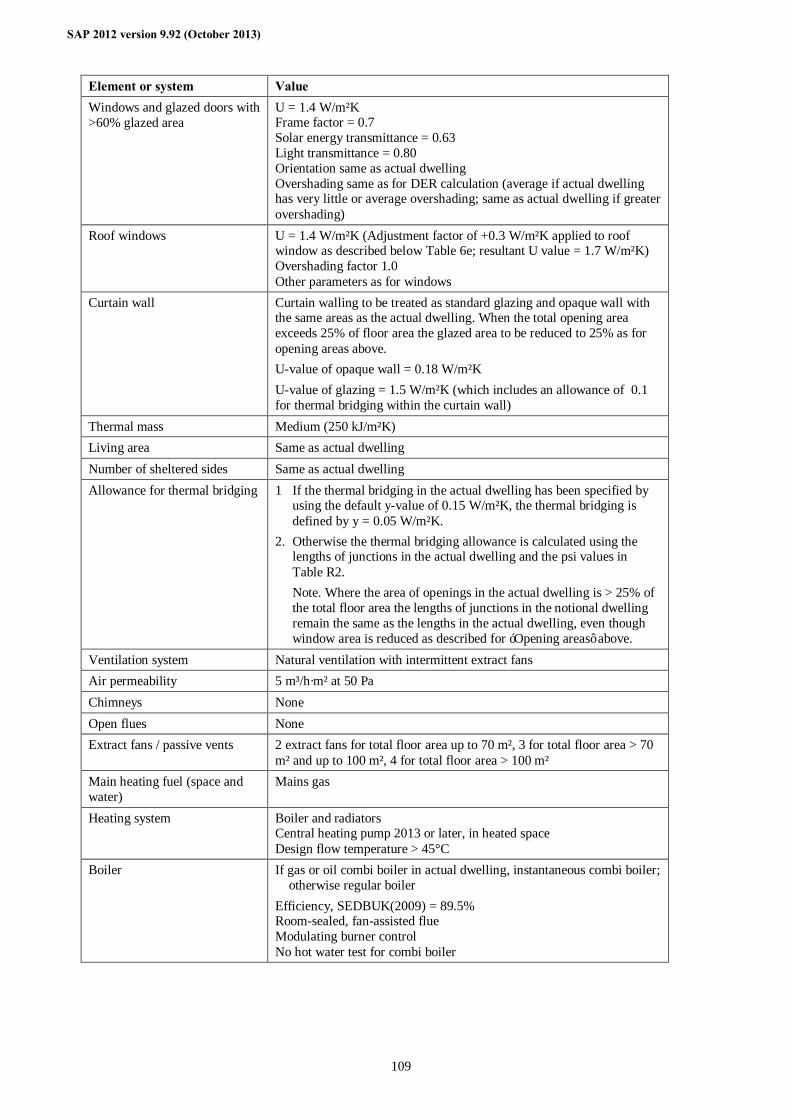
SAP 2012 version 9.92 (October 2013)
109
Element or system Value Windows and glazed doors with >60% glazed area
U = 1.4 W/m²K Frame factor = 0.7 Solar energy transmittance = 0.63 Light transmittance = 0.80 Orientation same as actual dwelling Overshading same as for DER calculation (average if actual dwelling has very little or average overshading; same as actual dwelling if greater overshading)
Roof windows U = 1.4 W/m²K (Adjustment factor of +0.3 W/m²K applied to roof window as described below Table 6e; resultant U value = 1.7 W/m²K) Overshading factor 1.0 Other parameters as for windows
Curtain wall Curtain walling to be treated as standard glazing and opaque wall with the same areas as the actual dwelling. When the total opening area exceeds 25% of floor area the glazed area to be reduced to 25% as for opening areas above. U-value of opaque wall = 0.18 W/m²K U-value of glazing = 1.5 W/m²K (which includes an allowance of 0.1 for thermal bridging within the curtain wall)
Thermal mass Medium (250 kJ/m²K) Living area Same as actual dwelling Number of sheltered sides Same as actual dwelling Allowance for thermal bridging 1 If the thermal bridging in the actual dwelling has been specified by
using the default y-value of 0.15 W/m²K, the thermal bridging is defined by y = 0.05 W/m²K.
2. Otherwise the thermal bridging allowance is calculated using the lengths of junctions in the actual dwelling and the psi values in Table R2.
Note. Where the area of openings in the actual dwelling is > 25% of the total floor area the lengths of junctions in the notional dwelling remain the same as the lengths in the actual dwelling, even though window area is reduced as described for ‘Opening areas’ above.
Ventilation system Natural ventilation with intermittent extract fans Air permeability 5 m³/h·m² at 50 Pa Chimneys None Open flues None Extract fans / passive vents 2 extract fans for total floor area up to 70 m², 3 for total floor area > 70
m² and up to 100 m², 4 for total floor area > 100 m² Main heating fuel (space and water)
Mains gas
Heating system Boiler and radiators Central heating pump 2013 or later, in heated space Design flow temperature > 45°C
Boiler If gas or oil combi boiler in actual dwelling, instantaneous combi boiler; otherwise regular boiler Efficiency, SEDBUK(2009) = 89.5% Room-sealed, fan-assisted flue Modulating burner control No hot water test for combi boiler
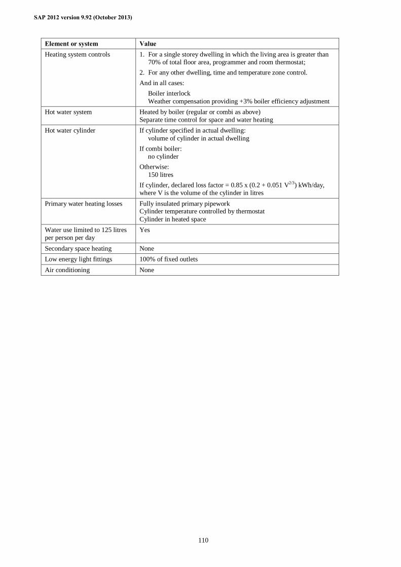
SAP 2012 version 9.92 (October 2013)
110
Element or system Value Heating system controls 1. For a single storey dwelling in which the living area is greater than
70% of total floor area, programmer and room thermostat; 2. For any other dwelling, time and temperature zone control. And in all cases: Boiler interlock Weather compensation providing +3% boiler efficiency adjustment
Hot water system Heated by boiler (regular or combi as above) Separate time control for space and water heating
Hot water cylinder If cylinder specified in actual dwelling: volume of cylinder in actual dwelling If combi boiler: no cylinder Otherwise: 150 litres If cylinder, declared loss factor = 0.85 x (0.2 + 0.051 V2/3) kWh/day, where V is the volume of the cylinder in litres
Primary water heating losses Fully insulated primary pipework Cylinder temperature controlled by thermostat Cylinder in heated space
Water use limited to 125 litres per person per day
Yes
Secondary space heating None Low energy light fittings 100% of fixed outlets Air conditioning None
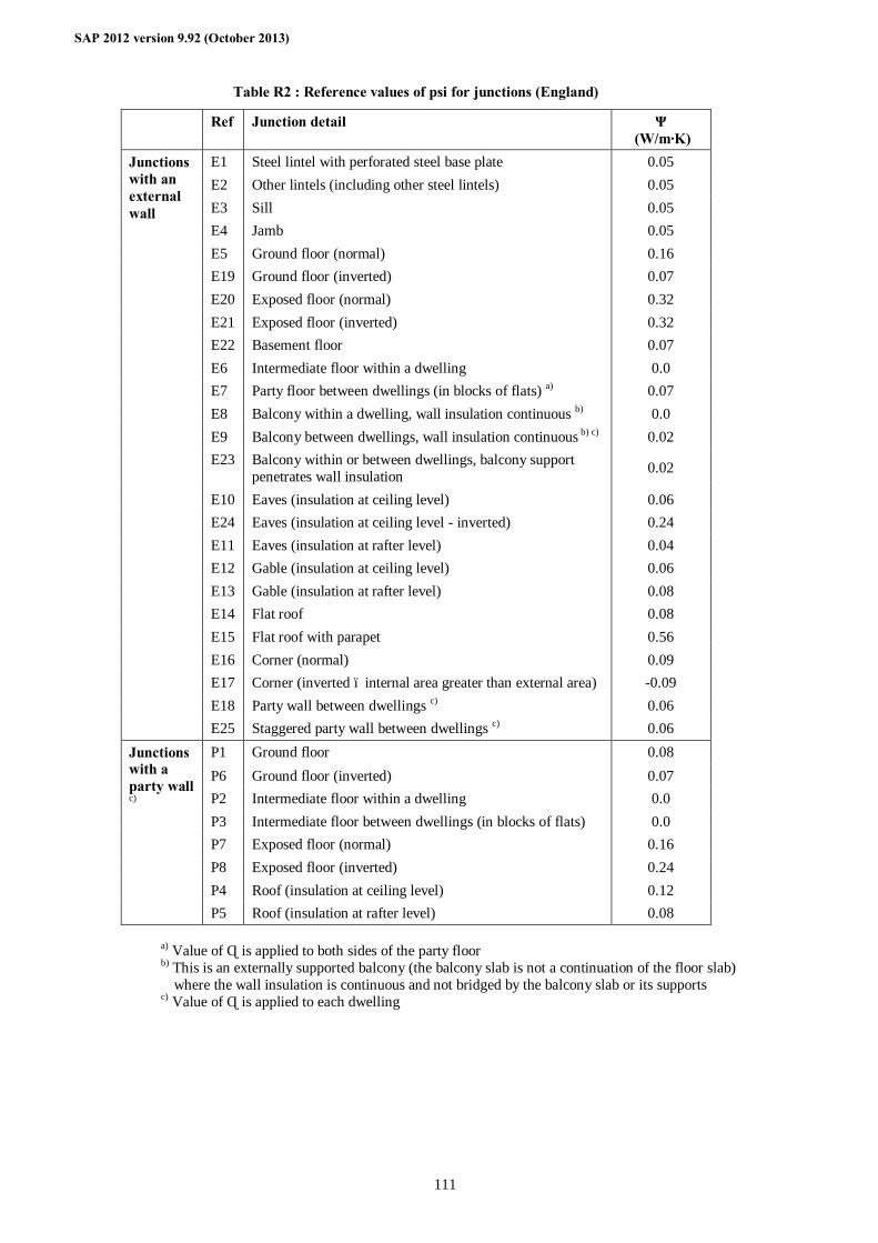
SAP 2012 version 9.92 (October 2013)
111
Table R2 : Reference values of psi for junctions (England)
Ref Junction detail Ψ (W/m·K)
E1 Steel lintel with perforated steel base plate 0.05 E2 Other lintels (including other steel lintels) 0.05 E3 Sill 0.05 E4 Jamb 0.05 E5 Ground floor (normal) 0.16 E19 Ground floor (inverted) 0.07 E20 Exposed floor (normal) 0.32 E21 Exposed floor (inverted) 0.32 E22 Basement floor 0.07 E6 Intermediate floor within a dwelling 0.0 E7 Party floor between dwellings (in blocks of flats) a) 0.07 E8 Balcony within a dwelling, wall insulation continuous b) 0.0 E9 Balcony between dwellings, wall insulation continuous b) c) 0.02 E23 Balcony within or between dwellings, balcony support
penetrates wall insulation 0.02
E10 Eaves (insulation at ceiling level) 0.06 E24 Eaves (insulation at ceiling level - inverted) 0.24 E11 Eaves (insulation at rafter level) 0.04 E12 Gable (insulation at ceiling level) 0.06 E13 Gable (insulation at rafter level) 0.08 E14 Flat roof 0.08 E15 Flat roof with parapet 0.56 E16 Corner (normal) 0.09 E17 Corner (inverted – internal area greater than external area) -0.09 E18 Party wall between dwellings c) 0.06
Junctions with an external wall
E25 Staggered party wall between dwellings c) 0.06 P1 Ground floor 0.08 P6 Ground floor (inverted) 0.07 P2 Intermediate floor within a dwelling 0.0 P3 Intermediate floor between dwellings (in blocks of flats) 0.0 P7 Exposed floor (normal) 0.16 P8 Exposed floor (inverted) 0.24 P4 Roof (insulation at ceiling level) 0.12
Junctions with a party wall c)
P5 Roof (insulation at rafter level) 0.08
a) Value of Ψ is applied to both sides of the party floor b) This is an externally supported balcony (the balcony slab is not a continuation of the floor slab)
where the wall insulation is continuous and not bridged by the balcony slab or its supports c) Value of Ψ is applied to each dwelling
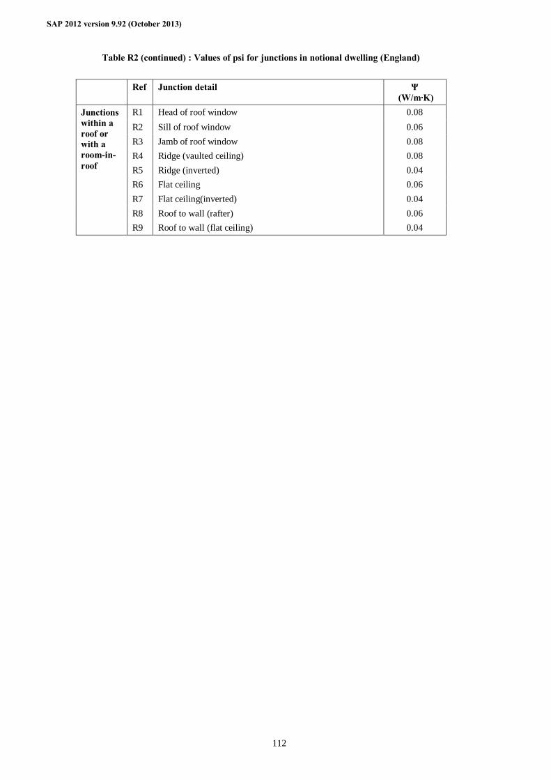
SAP 2012 version 9.92 (October 2013)
112
Table R2 (continued) : Values of psi for junctions in notional dwelling (England)
Ref Junction detail Ψ
(W/m·K) R1 Head of roof window 0.08 R2 Sill of roof window 0.06 R3 Jamb of roof window 0.08 R4 Ridge (vaulted ceiling) 0.08 R5 Ridge (inverted) 0.04 R6 Flat ceiling 0.06 R7 Flat ceiling(inverted) 0.04 R8 Roof to wall (rafter) 0.06
Junctions within a roof or with a room-in-roof
R9 Roof to wall (flat ceiling) 0.04
RdSAP 2012 version 9.92 (June 2014)
113
Appendix S: Reduced Data SAP for existing dwellings
Reduced Data SAP (RdSAP) has been developed by government for use in existing dwellings based on a site survey of the property, when the complete data set for a SAP calculation is not available. It consists of a system of data collection (defined in Table S19) together with defaults and inference procedures, as defined by the rules given in this Appendix, that generate a complete set of input data for the SAP calculation. For any item not mentioned in this Appendix, the procedures and data given elsewhere in this document apply. The calculation starting from reduced data is done in two stages. First the reduced data set is expanded into a full data set (see S14 for rounding rules), and then the SAP calculation is undertaken using the expanded data set. The actual SAP calculation is therefore identical, whether starting from a reduced data set or a full data set. This Appendix forms part of SAP 2012 and provides a methodology for existing dwellings that is compliant with the Energy Performance of Buildings Directive. It is not appropriate for new dwellings for which all data for the SAP calculation should be acquired related to the dwelling concerned. This Appendix contains the data and rules for expanding the data collected in a Reduced Data survey into the data required for the SAP calculation. Information in shaded boxes is primarily concerned with data collection and is addressed to energy assessors. Table S19 lists the Reduced Data set.
S1 Dwelling types Dwellings are classified as one of
– house – bungalow – flat – maisonette – park home
and one of – detached – semi-detached – mid-terrace – end-terrace – enclosed mid-terrace – enclosed end-terrace
Reduced Data SAP is for existing dwellings only. Any new dwelling, including (except in Scotland) dwellings created by change of use, must be assessed using SAP.
A house or bungalow has a complete heat loss ground floor and a completely exposed roof. A dwelling without a heat loss floor cannot be a house and must be treated as a flat or maisonette. A flat or maisonette does not have both a heat loss ground floor and a heat loss roof. RdSAP makes no distinction between a flat and a maisonette as regards calculations; it is acceptable to select either type as definitions vary across the UK. ‘Enclosed’ is typically applicable for ‘back-to-back’ terraces and has the following meaning:
– mid-terrace has external walls on two opposite sides; – enclosed mid terrace has an external wall on one side only; – end-terrace has three external walls; – enclosed end-terrace has two adjacent external walls.
Many dwellings have one or more extensions either added onto the main part, or built at the same time but of different construction or insulation. In these cases, dimensions and constructional details of the main part of the dwelling and each extension are recorded separately, to allow the assignment of different U-values to the original and to the extension. In addition, dwellings can have a different construction for some parts of the walls (for example, a timber framed bay window in otherwise masonry construction). These are recorded as a separate constructional element, termed ‘alternative wall’. If the area of an alternative wall is less than 10% of the total wall area it can be disregarded.
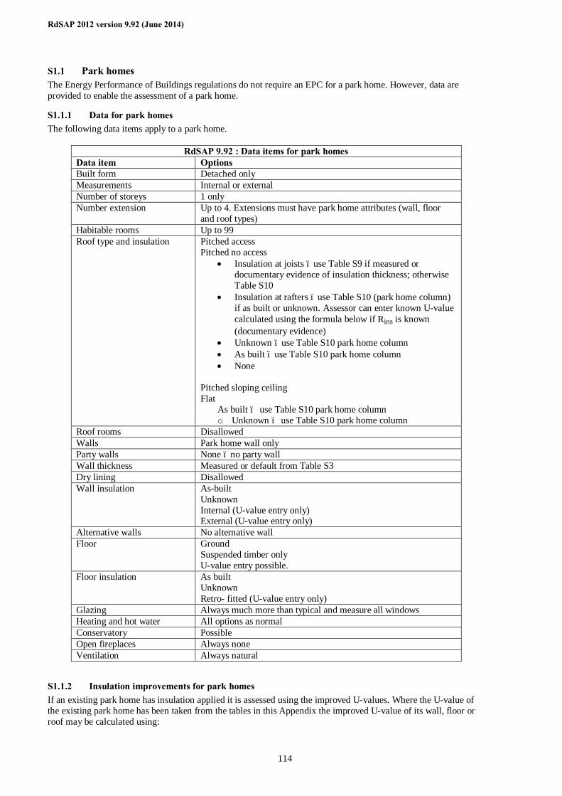
RdSAP 2012 version 9.92 (June 2014)
114
S1.1 Park homes The Energy Performance of Buildings regulations do not require an EPC for a park home. However, data are provided to enable the assessment of a park home.
S1.1.1 Data for park homes The following data items apply to a park home.
RdSAP 9.92 : Data items for park homes Data item Options Built form Detached only Measurements Internal or external Number of storeys 1 only Number extension Up to 4. Extensions must have park home attributes (wall, floor
and roof types) Habitable rooms Up to 99 Roof type and insulation Pitched access
Pitched no access • Insulation at joists – use Table S9 if measured or
documentary evidence of insulation thickness; otherwise Table S10
• Insulation at rafters – use Table S10 (park home column) if as built or unknown. Assessor can enter known U-value calculated using the formula below if Rins is known (documentary evidence)
• Unknown – use Table S10 park home column • As built – use Table S10 park home column • None
Pitched sloping ceiling Flat
As built – use Table S10 park home column o Unknown – use Table S10 park home column
Roof rooms Disallowed Walls Park home wall only Party walls None – no party wall Wall thickness Measured or default from Table S3 Dry lining Disallowed Wall insulation As-built
Unknown Internal (U-value entry only) External (U-value entry only)
Alternative walls No alternative wall Floor Ground
Suspended timber only U-value entry possible.
Floor insulation As built Unknown Retro- fitted (U-value entry only)
Glazing Always much more than typical and measure all windows Heating and hot water All options as normal Conservatory Possible Open fireplaces Always none Ventilation Always natural
S1.1.2 Insulation improvements for park homes If an existing park home has insulation applied it is assessed using the improved U-values. Where the U-value of the existing park home has been taken from the tables in this Appendix the improved U-value of its wall, floor or roof may be calculated using:
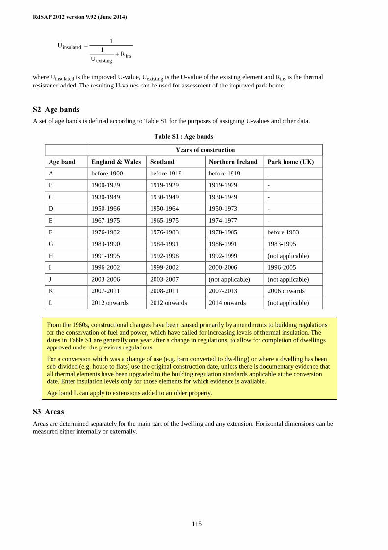
RdSAP 2012 version 9.92 (June 2014)
115
insexisting
insulatedR
U1
1U+
=
where Uinsulated is the improved U-value, Uexisting is the U-value of the existing element and Rins is the thermal resistance added. The resulting U-values can be used for assessment of the improved park home.
S2 Age bands A set of age bands is defined according to Table S1 for the purposes of assigning U-values and other data.
Table S1 : Age bands
Years of construction
Age band England & Wales Scotland Northern Ireland Park home (UK)
A before 1900 before 1919 before 1919 -
B 1900-1929 1919-1929 1919-1929 -
C 1930-1949 1930-1949 1930-1949 -
D 1950-1966 1950-1964 1950-1973 -
E 1967-1975 1965-1975 1974-1977 -
F 1976-1982 1976-1983 1978-1985 before 1983
G 1983-1990 1984-1991 1986-1991 1983-1995
H 1991-1995 1992-1998 1992-1999 (not applicable)
I 1996-2002 1999-2002 2000-2006 1996-2005
J 2003-2006 2003-2007 (not applicable) (not applicable)
K 2007-2011 2008-2011 2007-2013 2006 onwards
L 2012 onwards 2012 onwards 2014 onwards (not applicable)
S3 Areas Areas are determined separately for the main part of the dwelling and any extension. Horizontal dimensions can be measured either internally or externally.
From the 1960s, constructional changes have been caused primarily by amendments to building regulations for the conservation of fuel and power, which have called for increasing levels of thermal insulation. The dates in Table S1 are generally one year after a change in regulations, to allow for completion of dwellings approved under the previous regulations.
For a conversion which was a change of use (e.g. barn converted to dwelling) or where a dwelling has been sub-divided (e.g. house to flats) use the original construction date, unless there is documentary evidence that all thermal elements have been upgraded to the building regulation standards applicable at the conversion date. Enter insulation levels only for those elements for which evidence is available.
Age band L can apply to extensions added to an older property.

RdSAP 2012 version 9.92 (June 2014)
116
The measurements required are the floor area, exposed perimeter, party wall length and room height on each storey. Exposed perimeter includes the wall between the dwelling and an unheated garage or a separated conservatory and, in the case of a flat or maisonette, the wall between the dwelling and an unheated corridor.
Internal dimensions are permissible in all cases. In the case of a house or bungalow external dimensions for area and perimeter are usually more convenient, except where access to all sides of the building is not possible or where there are differing wall thicknesses or other aspects that would make the dimensional conversion unreliable. When using external measurements for a dwelling joined onto another dwelling (semi-detached and terraced houses) the measurement is to the mid-point of the party wall. Flats and maisonettes are usually measured internally (although it is not a requirement of the specification that internal measurements are always used and if measured externally the measurement is to the mid-point of the party wall). Whichever is chosen the same basis must be used for all parts of the dwelling. Party wall length uses the same basis as exposed perimeter.
Room heights are always measured internally within the room.
State on site plans whether the dimensions recorded are external or internal. Where a combination of external and internal is used this must be made clear for each dimension indicated.
When measuring internally, measure between the finished internal surfaces of the walls bounding the dwelling. Where that cannot be done directly (i.e. when measuring room by room) include an allowance for the thickness of internal partitions.
Measure all perturbations (e.g. bay windows) but disregard chimney breasts unless assessor considers significant e.g. large inglenook.
Vertical dimensions (room heights) are always measured internally within the room. Also, the floor area of room(s)-in-roof are always measured internally (irrespective of the dimensions basis for other storeys).
Measure lengths to one decimal place (0.1 m) or better. Retain higher precision when that has been measured (especially room heights).
If there is an alternative wall, it is identified as being part of the external wall of main dwelling or of one of the extensions. When calculating the area of alternative wall exclude the area of any windows and doors contained within it.

RdSAP 2012 version 9.92 (June 2014)
117
S3.1 Definition of the extent of the dwelling Generally rooms and other spaces, such as built-in cupboards, are included as part of the dwelling where these are directly accessible from the occupied area of the dwelling, whereas unheated spaces clearly divided from the dwelling are not.
Basements Include in the assessment when accessed via a permanent fixed staircase such that one is able to walk downwards facing forwards and either:- - basement is heated via fixed heat emitters, or - basement is open to the rest of the dwelling.
A basement does not necessarily contain habitable rooms. Do not mix internal and external measurements. If a basement is included in the assessment, it is likely that internal dimensions will be used throughout the dwelling. Attics and roof rooms
Include in the assessment when accessed via a permanent fixed staircase such that one is able to walk downwards facing forwards. Does not necessarily contain habitable rooms.
For a roof room to be classed as such and not a separate storey, the height of the common wall must be less than 1.8 m for at least 50% of the common wall (excluding gable ends or party walls). The common wall is a vertical continuation of the external wall of the storey below.
There is no explicit allowance for dormer windows except to include in the floor area of the roof rooms. See Figures S1 and S2 (next page). Rooms within a Mansard roof A storey having non-vertical walls of at least 70° pitch constitutes a separate storey; it is not treated as roof rooms. Use alternative wall if appropriate. Whole dwelling within roof When property is a single storey entirely located within a roof, enter it as: - lowest occupied level - timber frame construction of appropriate age band - room height 2.2 m - include area and perimeter measurements as a normal storey - enter roof as pitched roof. If there are two storeys within roof, enter the lower storey as above and the upper storey as rooms-in-roof.
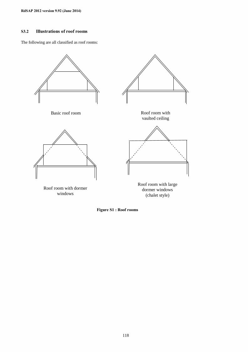
RdSAP 2012 version 9.92 (June 2014)
118
S3.2 Illustrations of roof rooms The following are all classified as roof rooms:
Figure S1 : Roof rooms
Roof room with dormer windows
Roof room with large dormer windows
(chalet style)
Basic roof room Roof room with vaulted ceiling
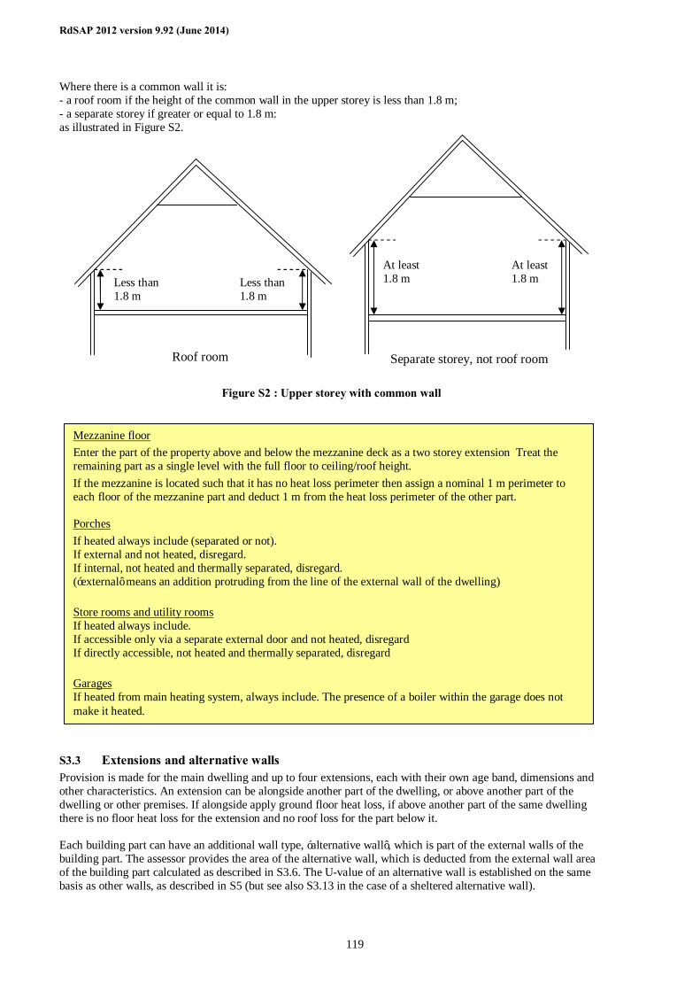
RdSAP 2012 version 9.92 (June 2014)
119
Where there is a common wall it is: - a roof room if the height of the common wall in the upper storey is less than 1.8 m; - a separate storey if greater or equal to 1.8 m: as illustrated in Figure S2.
Figure S2 : Upper storey with common wall
S3.3 Extensions and alternative walls Provision is made for the main dwelling and up to four extensions, each with their own age band, dimensions and other characteristics. An extension can be alongside another part of the dwelling, or above another part of the dwelling or other premises. If alongside apply ground floor heat loss, if above another part of the same dwelling there is no floor heat loss for the extension and no roof loss for the part below it. Each building part can have an additional wall type, ‘alternative wall’, which is part of the external walls of the building part. The assessor provides the area of the alternative wall, which is deducted from the external wall area of the building part calculated as described in S3.6. The U-value of an alternative wall is established on the same basis as other walls, as described in S5 (but see also S3.13 in the case of a sheltered alternative wall).
Less than 1.8 m
Less than 1.8 m
Roof room
At least 1.8 m
At least 1.8 m
Separate storey, not roof room
Mezzanine floor Enter the part of the property above and below the mezzanine deck as a two storey extension Treat the remaining part as a single level with the full floor to ceiling/roof height. If the mezzanine is located such that it has no heat loss perimeter then assign a nominal 1 m perimeter to each floor of the mezzanine part and deduct 1 m from the heat loss perimeter of the other part. Porches If heated always include (separated or not). If external and not heated, disregard. If internal, not heated and thermally separated, disregard. (‘external’ means an addition protruding from the line of the external wall of the dwelling) Store rooms and utility rooms If heated always include. If accessible only via a separate external door and not heated, disregard If directly accessible, not heated and thermally separated, disregard Garages If heated from main heating system, always include. The presence of a boiler within the garage does not make it heated.
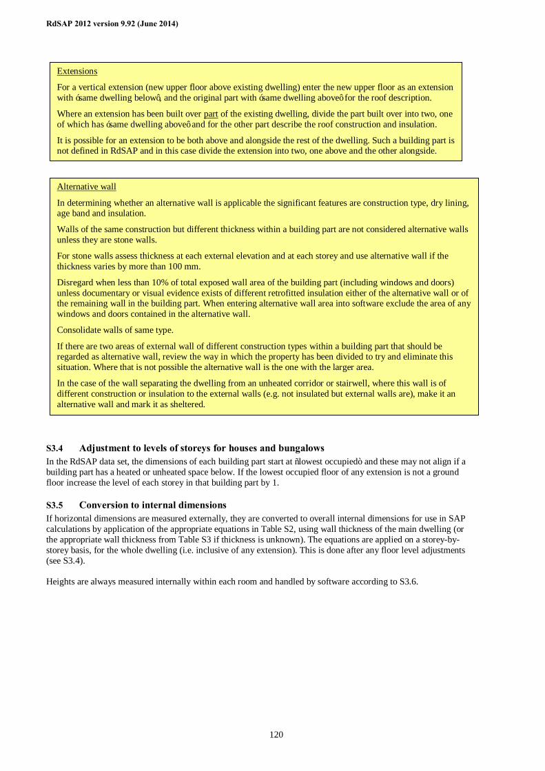
RdSAP 2012 version 9.92 (June 2014)
120
S3.4 Adjustment to levels of storeys for houses and bungalows In the RdSAP data set, the dimensions of each building part start at “lowest occupied” and these may not align if a building part has a heated or unheated space below. If the lowest occupied floor of any extension is not a ground floor increase the level of each storey in that building part by 1.
S3.5 Conversion to internal dimensions If horizontal dimensions are measured externally, they are converted to overall internal dimensions for use in SAP calculations by application of the appropriate equations in Table S2, using wall thickness of the main dwelling (or the appropriate wall thickness from Table S3 if thickness is unknown). The equations are applied on a storey-by-storey basis, for the whole dwelling (i.e. inclusive of any extension). This is done after any floor level adjustments (see S3.4). Heights are always measured internally within each room and handled by software according to S3.6.
Alternative wall
In determining whether an alternative wall is applicable the significant features are construction type, dry lining, age band and insulation.
Walls of the same construction but different thickness within a building part are not considered alternative walls unless they are stone walls.
For stone walls assess thickness at each external elevation and at each storey and use alternative wall if the thickness varies by more than 100 mm.
Disregard when less than 10% of total exposed wall area of the building part (including windows and doors) unless documentary or visual evidence exists of different retrofitted insulation either of the alternative wall or of the remaining wall in the building part. When entering alternative wall area into software exclude the area of any windows and doors contained in the alternative wall.
Consolidate walls of same type.
If there are two areas of external wall of different construction types within a building part that should be regarded as alternative wall, review the way in which the property has been divided to try and eliminate this situation. Where that is not possible the alternative wall is the one with the larger area.
In the case of the wall separating the dwelling from an unheated corridor or stairwell, where this wall is of different construction or insulation to the external walls (e.g. not insulated but external walls are), make it an alternative wall and mark it as sheltered.
Extensions
For a vertical extension (new upper floor above existing dwelling) enter the new upper floor as an extension with ‘same dwelling below’, and the original part with ‘same dwelling above’ for the roof description.
Where an extension has been built over part of the existing dwelling, divide the part built over into two, one of which has ‘same dwelling above’ and for the other part describe the roof construction and insulation.
It is possible for an extension to be both above and alongside the rest of the dwelling. Such a building part is not defined in RdSAP and in this case divide the extension into two, one above and the other alongside.
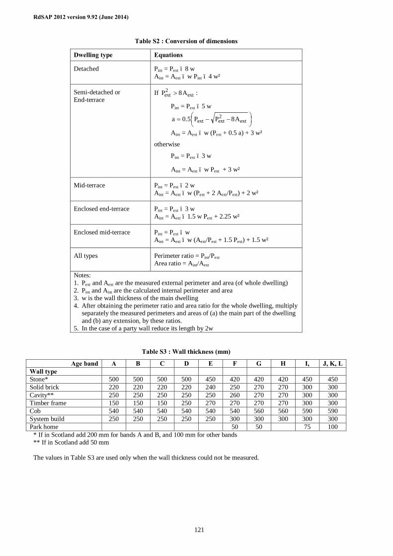
RdSAP 2012 version 9.92 (June 2014)
121
Table S2 : Conversion of dimensions
Dwelling type Equations
Detached Pint = Pext – 8 w Aint = Aext – w Pint – 4 w²
Semi-detached or End-terrace
If ext2ext A8P > :
Pint = Pext – 5 w
−−= ext
2extext A8PP5.0a
Aint = Aext – w (Pext + 0.5 a) + 3 w²
otherwise
Pint = Pext – 3 w
Aint = Aext – w Pext + 3 w²
Mid-terrace Pint = Pext – 2 w Aint = Aext – w (Pext + 2 Aext/Pext) + 2 w²
Enclosed end-terrace Pint = Pext – 3 w Aint = Aext – 1.5 w Pext + 2.25 w²
Enclosed mid-terrace Pint = Pext – w Aint = Aext – w (Aext/Pext + 1.5 Pext) + 1.5 w²
All types Perimeter ratio = Pint/Pext Area ratio = Aint/Aext
Notes: 1. Pext and Aext are the measured external perimeter and area (of whole dwelling) 2. Pint and Aint are the calculated internal perimeter and area 3. w is the wall thickness of the main dwelling 4. After obtaining the perimeter ratio and area ratio for the whole dwelling, multiply
separately the measured perimeters and areas of (a) the main part of the dwelling and (b) any extension, by these ratios.
5. In the case of a party wall reduce its length by 2w
Table S3 : Wall thickness (mm)
Age band A B C D E F G H I, J, K, L Wall type Stone* 500 500 500 500 450 420 420 420 450 450 Solid brick 220 220 220 220 240 250 270 270 300 300 Cavity** 250 250 250 250 250 260 270 270 300 300 Timber frame 150 150 150 250 270 270 270 270 300 300 Cob 540 540 540 540 540 540 560 560 590 590 System build 250 250 250 250 250 300 300 300 300 300 Park home 50 50 75 100
* If in Scotland add 200 mm for bands A and B, and 100 mm for other bands ** If in Scotland add 50 mm The values in Table S3 are used only when the wall thickness could not be measured.
RdSAP 2012 version 9.92 (June 2014)
122
S3.6 Heights and exposed wall areas Heights are measured internally within each room, and 0.25 m is added by software to each room height except for the lowest storey, to obtain the storey height. For this purpose the lowest storey is considered separately for each building part (main dwelling and any extension). The lowest storey of a building part is the lowest for the dwelling unless it has been indicated as having the same dwelling below. Gross areas (inclusive of openings) are obtained from the product of heat loss perimeter (after conversion to internal dimensions if relevant) and storey height, summed over all storeys. Party wall area is party wall length multiplied by storey height, summed over all storeys. For the main dwelling and any extension(s), window and door areas are deducted from the gross areas to obtain the net wall areas for the heat loss calculations, except for the door of a flat/maisonette to an unheated stair or corridor which is deducted from the sheltered wall area (see S3.13). If an alternative wall is present, the area of the alternative wall is recorded net of any openings in it and the alternative wall is identified as part of the main wall or extension wall. This area is subtracted from the net wall area of the building part prior to the calculation of wall heat losses.
S3.7 Door and window areas The area of an external door is taken as 1.85 m². A door to a heated access corridor is not included in the door count. External doors except doors to an unheated corridor or stairwell are taken as being in the main part of the dwelling. The door to an unheated corridor or stairwell is taken as part of the sheltered wall it is within, and so is in the building part containing the sheltered alternative wall (so not necessarily in the main dwelling). If the property has more than one door, doors except the first one are directly to the outside and taken as being in the main part of the dwelling. Total window area is assessed as being typical, more than typical, much more than typical, less than typical, or much less than typical.
S3.7.1 Window area typical, more than typical or less than typical Window areas are obtained by application of the appropriate equation from Table S4. The equation used is chosen according to the age band of the main part of the dwelling, with the resulting total window area apportioned between main part and extension(s) pro rata to their floor areas. If the window area of any part of the dwelling (main, extension, 2nd extension etc) is greater than 90% of the exposed façade area of that part, after deducting doors and alternative wall area if applicable to that part, the window area is set equal to 90% of the façade area.
Table S4 : Window area (m²)
Age band of main dwelling
House or Bungalow Flat or Maisonette
In RdSAP the definition of what is a window and what is a door is defined by the area of glazing in relation to the area of the whole opening, i.e. door and frame. To be classed as a window a glazed door and frame must contain glazing amounting to 60% or more or its surface area. Generally 60% or more glazing is likely to occur only in a patio door. An external door is a door that forms part of the heat loss perimeter of the dwelling. A door to a heated access corridor is not included in the door count.
Wall thickness Measure wall thickness in mm of each external wall (elevation) and any alternative wall within a building part.
It can be measured at door or window reveals or by internal/external measurement comparison (which can be direct measurement or estimated by counting bricks). Where thickness varies, obtain a weighted average. For example, a detached house with all side of equal length where the rear wall is 250 mm thick and the remaining walls are 350 mm thick, the average is (0.25 × 250) + (0.75 × 350) = 325 mm.
RdSAP 2012 version 9.92 (June 2014)
123
Age band of main dwelling
House or Bungalow Flat or Maisonette
A, B ,C WA = 0.1220 TFA + 6.875 WA = 0.0801 TFA + 5.580
D WA = 0.1294 TFA + 5.515 WA = 0.0341 TFA + 8.562
E WA = 0.1239 TFA + 7.332 WA = 0.0717 TFA + 6.560
F WA = 0.1252 TFA + 5.520 WA = 0.1199 TFA + 1.975
G WA = 0.1356 TFA + 5.242 WA = 0.0510 TFA + 4.554
H WA = 0.0948 TFA + 6.534 WA = 0.0813 TFA + 3.744
I WA = 0.1382 TFA – 0.027 WA = 0.1148 TFA + 0.392
J, K, L WA = 0.1435 TFA – 0.403 WA = 0.1148 TFA + 0.392
WA = window area TFA = total floor area of main part plus any extension
This does not include conservatories, which are treated separately: see S5.9. The window areas calculated using Table S4 are to be reduced by 25% if it is assessed as being less than typical for the age and type of property, and increased by 25% if assessed as being more than typical for the age and type of property.
When assessing window area consider the whole dwelling (windows, glazed doors and roof lights), including any extensions (but not conservatories).
Typical applies if the surface area of the glazing in the dwelling is essentially as would be expected of a typical property of that age, type, size and character. Even if there is slightly more or less glazing than would be expected, up to 10% more or less.
More than typical applies if there is significantly more surface area of glazing than would be expected (15%-30% more), perhaps because there is a large sun room or numerous patio doors have been added.
Less than typical applies if there is significantly less glazing than would be expected. This is rare as homeowners tend not to take out windows, but a property may have an unusual design with few windows. Much more than typical and Much less than typical should be used for those dwellings with very unusual amounts of glazing; such as a glass walled penthouse flat or a Huff Haus. Due to this option allowing measurements of each window to be accounted for, it can also be used if a dwelling has a mixture of glazing types e.g. single, double and triple. Sun rooms For a highly glazed part of the dwelling, such as a sun room, which does not meet the criteria for a conservatory (50% of walls and 75% of roof glazed), in most cases use the glazing option of ‘more than typical’. That adds 25% to the total glazed area of the dwelling. If that is considered not appropriate, the window area is assessed by either:
a) measuring all windows and roof windows throughout the dwelling, or
b) measuring all windows and roof windows in the sun room, and use Table S4 to obtain the window area of remaining part of dwelling which is entered as a single window. Record method used in site notes.
RdSAP 2012 version 9.92 (June 2014)
124
Two types of window are allowed for, single and multiple glazed. Multiple glazing can be double glazed units installed before 200227, double glazed units installed during/after 200227, double glazing unknown date, secondary glazing or triple glazing. For multiple glazing the U-value can be known. The window area of each part of the dwelling (main, extension 1, extension 2 etc) is divided into two areas, single and multiple, according to the assessor's estimate of the multiple-glazed percentage. The same percentage is used in main dwelling and each extension.
S3.7.2 Window area much more or much less than typical, and park homes If window area is assessed as much greater than typical or as much less than typical, the total window area should be obtained from measurements of each individual window. That also applies to park homes. In this case the location area of each window in the main part of the dwelling and in any extension are recorded separately, along with: - single glazed, double glazed before or during/after 200227, secondary glazing or triple glazed; - U-value if known - window or roof window; - orientation and Table S4 is not used. In this case there can be several types of window. The multiple-glazed percentage is calculated on the basis of the area and type of each window or roof window. If external dimensions were used, all windows were measured and there is a roof window with area greater than the roof area of the building part concerned, change the roof window area to be equal to the roof area. This can occur with a fully glazed roof because the roof window area entered by the assessor does not take account of the reduction in areas that occurs when the dimensions are converted from external to internal.
S3.8 Roof area Roof area is the greatest of the floor areas on each level, calculated separately for main dwelling and any extension. In the case of a pitched roof with a sloping ceiling, divide the area so obtained by cos(30°).
S3.9 Rooms in roof The following procedure is applied to main dwelling and separately to any extension with roof rooms as applicable. Note. A roof room cannot be an extension in its own right, roof rooms are defined only when a building part consisting of normal storey(s) has been defined. If there are roof rooms, with a total floor area of Frr (measured internally), then: (1) Area Frr is deducted from the roof area determined at S3.8. (2) A separate heat-loss roof of area Arr = Frr is defined. (3) A separate heat-loss wall of area Arw is defined , where
5.1/F0.11A rrrw = where the roof rooms are not connected to another building part, or
5.1/F25.8A rrrw = where the roof rooms are connected to another building part. Roof rooms are ‘connected’ if they are adjacent to (i.e. at the same level as) another building part of the same dwelling. The adjacent part can be another roof room or a normal storey.
27 2002 in England & Wales, 2003 in Scotland, 2006 in Northern Ireland
If more than one of type of multiple glazing is present, the assessor selects the type according to what is the most prevalent in the dwelling.
If single glazing with secondary glazing, record as secondary glazing.
If double glazing with secondary glazing, record as newer double glazing (i.e. later than the date in footnote 27).
If secondary glazing has been removed in summer, enter as secondary glazing only if assessor can confirm that the panels exist and can be re-fitted. Evidence to be recorded on site notes.
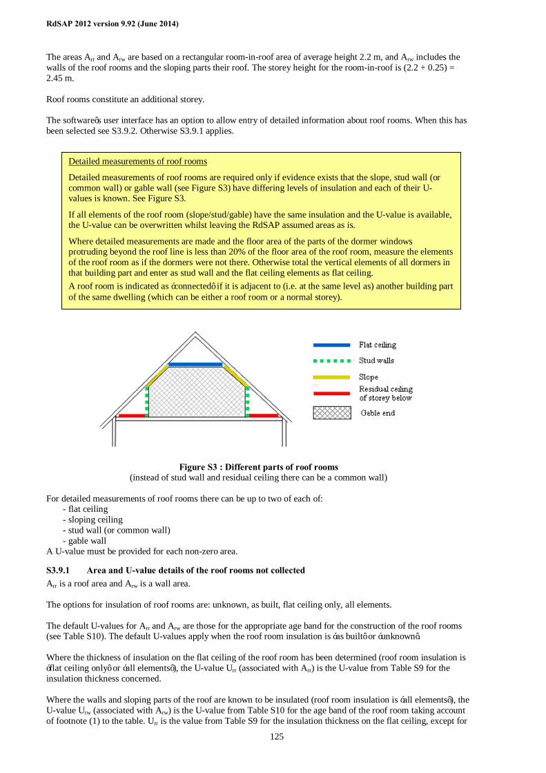
RdSAP 2012 version 9.92 (June 2014)
125
The areas Arr and Arw are based on a rectangular room-in-roof area of average height 2.2 m, and Arw includes the walls of the roof rooms and the sloping parts their roof. The storey height for the room-in-roof is (2.2 + 0.25) = 2.45 m. Roof rooms constitute an additional storey. The software’s user interface has an option to allow entry of detailed information about roof rooms. When this has been selected see S3.9.2. Otherwise S3.9.1 applies.
Figure S3 : Different parts of roof rooms (instead of stud wall and residual ceiling there can be a common wall)
For detailed measurements of roof rooms there can be up to two of each of:
- flat ceiling - sloping ceiling - stud wall (or common wall) - gable wall
A U-value must be provided for each non-zero area.
S3.9.1 Area and U-value details of the roof rooms not collected Arr is a roof area and Arw is a wall area. The options for insulation of roof rooms are: unknown, as built, flat ceiling only, all elements. The default U-values for Arr and Arw are those for the appropriate age band for the construction of the roof rooms (see Table S10). The default U-values apply when the roof room insulation is ‘as built’ or ‘unknown’. Where the thickness of insulation on the flat ceiling of the roof room has been determined (roof room insulation is ‘flat ceiling only’ or ‘all elements’), the U-value Urr (associated with Arr) is the U-value from Table S9 for the insulation thickness concerned. Where the walls and sloping parts of the roof are known to be insulated (roof room insulation is ‘all elements’), the U-value Urw (associated with Arw) is the U-value from Table S10 for the age band of the roof room taking account of footnote (1) to the table. Urr is the value from Table S9 for the insulation thickness on the flat ceiling, except for
Detailed measurements of roof rooms
Detailed measurements of roof rooms are required only if evidence exists that the slope, stud wall (or common wall) or gable wall (see Figure S3) have differing levels of insulation and each of their U-values is known. See Figure S3.
If all elements of the roof room (slope/stud/gable) have the same insulation and the U-value is available, the U-value can be overwritten whilst leaving the RdSAP assumed areas as is.
Where detailed measurements are made and the floor area of the parts of the dormer windows protruding beyond the roof line is less than 20% of the floor area of the roof room, measure the elements of the roof room as if the dormers were not there. Otherwise total the vertical elements of all dormers in that building part and enter as stud wall and the flat ceiling elements as flat ceiling. A roof room is indicated as ‘connected’ if it is adjacent to (i.e. at the same level as) another building part of the same dwelling (which can be either a roof room or a normal storey).
RdSAP 2012 version 9.92 (June 2014)
126
a vaulted roof when the insulation of the flat ceiling is marked as ‘not applicable’ and for the purposes of the calculation Urr = Urw. The residual area (area of roof determined at S3.8 less the floor area of room(s)-in-roof) has a U-value according to its insulation thickness if at least half the area concerned is accessible, otherwise it is the default for the age band of the original property or extension.
S3.9.2 Area and U-value details of the roof rooms are collected Arr and Arw (see S3.9) and their corresponding U-values are to be calculated and shown on the software’s user interface to guide the assessor. The assessor over-writes these values as appropriate. The data supplied by the assessor are used directly in the SAP calculations. This consists of the area and U-value of up to 8 elements: two each of flat ceiling, sloping roof, stud walls (or common wall) and gable walls. See Figure S3 above.
S3.10 Heat loss floor area The lowest floor of a part of a dwelling (‘part’ means main dwelling or any extension) can be a basement, a ground floor, an exposed floor (external air below e.g. over a passageway) or a semi-exposed floor (unheated space below e.g. over an integral garage) or not a heat loss floor (upper flats/maisonettes or same or another dwelling below). If it is a basement it is treated as if it were a ground floor for heat loss purposes.
S3.11 Heat loss floor area for houses and bungalows The area of the lowest occupied floor of the main dwelling is a ground floor. If the lowest occupied floor of any extension is not a ground floor the level of each storey in that building part is increased by 1 as described in S3.4. For each building part examine the floor areas on each storey. If the area of any upper floor is greater than that of the floor below, the difference in these areas is an exposed or semi-exposed floor. This can occur particularly when there is an integral garage. When external dimensions are being used, however, the method of dimensional conversion can result in a small, but spurious, exposed floor area. To avoid that situation., the area of exposed floor on any level cannot be greater than the difference between the area of the current floor and the floor below measured using external dimensions. This rule is implemented as follows:
1. Calculate the exposed floor area before converting dimensions, call this A1 2. Convert dimensions 3. Calculate exposed floor area from the internal areas, call this A2 4. If A2 ≤ A1 the exposed floor area is A2 5. If A2 > A1 the exposed floor area is A1 6. Repeat for all levels if dwelling has more than two storeys, and obtain the total exposed floor area.
When dimensions have been measured internally, the exposed floor area is simply the difference in area between the current floor and the floor below. Semi-exposed floors are treated as if they were fully exposed. The ground floor area of the main dwelling and that of any extension are treated separately as they can have different U-values.
S3.12 Heat loss floor area for flats and maisonettes There is no heat loss through the floor if there is another flat below. Otherwise the floor area of the flat, or the lower floor of the maisonette, is:
- an exposed floor if there is an open space below; - a semi-exposed floor if there are unheated premises below it (e.g. an enclosed garage); - above a partially heated space if there are non-domestic premises below (heated, but at different times); - a ground floor if there is ground below
Semi exposed floors are treated as if they were fully exposed.
S3.13 Sheltered walls for flats and maisonettes If the flat or maisonette is adjacent to an unheated corridor or stairwell, the area of wall between the dwelling and the corridor or stairwell is treated as a sheltered (semi-exposed) wall, see S5.2. The area of sheltered wall is the shelter length multiplied by the height of the lowest storey, less the door area (see S3.6 and S3.7). The resulting
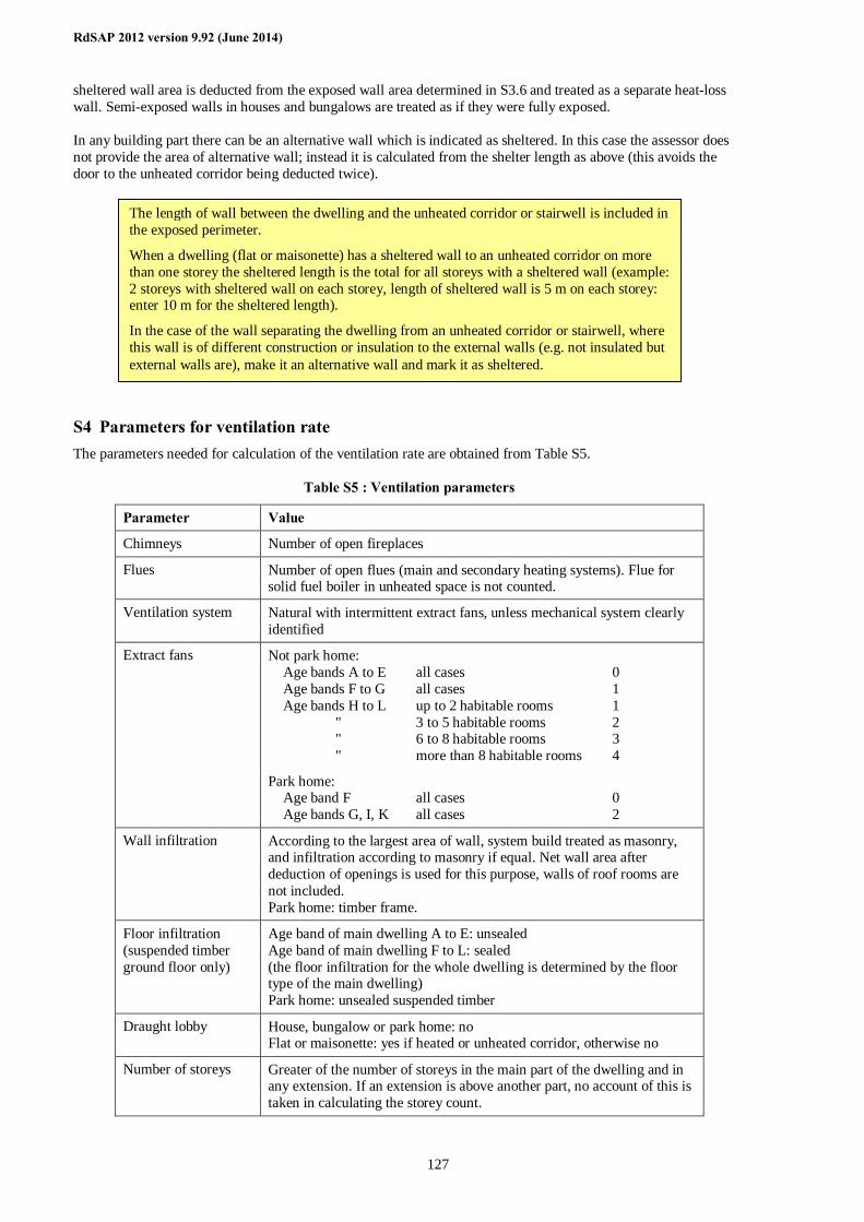
RdSAP 2012 version 9.92 (June 2014)
127
sheltered wall area is deducted from the exposed wall area determined in S3.6 and treated as a separate heat-loss wall. Semi-exposed walls in houses and bungalows are treated as if they were fully exposed. In any building part there can be an alternative wall which is indicated as sheltered. In this case the assessor does not provide the area of alternative wall; instead it is calculated from the shelter length as above (this avoids the door to the unheated corridor being deducted twice).
S4 Parameters for ventilation rate The parameters needed for calculation of the ventilation rate are obtained from Table S5.
Table S5 : Ventilation parameters
Parameter Value
Chimneys Number of open fireplaces
Flues Number of open flues (main and secondary heating systems). Flue for solid fuel boiler in unheated space is not counted.
Ventilation system Natural with intermittent extract fans, unless mechanical system clearly identified
Extract fans Not park home: Age bands A to E Age bands F to G Age bands H to L " " "
Park home: Age band F Age bands G, I, K
all cases all cases up to 2 habitable rooms 3 to 5 habitable rooms 6 to 8 habitable rooms more than 8 habitable rooms
all cases all cases
0 1 1 2 3 4
0 2
Wall infiltration According to the largest area of wall, system build treated as masonry, and infiltration according to masonry if equal. Net wall area after deduction of openings is used for this purpose, walls of roof rooms are not included. Park home: timber frame.
Floor infiltration (suspended timber ground floor only)
Age band of main dwelling A to E: unsealed Age band of main dwelling F to L: sealed (the floor infiltration for the whole dwelling is determined by the floor type of the main dwelling) Park home: unsealed suspended timber
Draught lobby House, bungalow or park home: no Flat or maisonette: yes if heated or unheated corridor, otherwise no
Number of storeys Greater of the number of storeys in the main part of the dwelling and in any extension. If an extension is above another part, no account of this is taken in calculating the storey count.
The length of wall between the dwelling and the unheated corridor or stairwell is included in the exposed perimeter.
When a dwelling (flat or maisonette) has a sheltered wall to an unheated corridor on more than one storey the sheltered length is the total for all storeys with a sheltered wall (example: 2 storeys with sheltered wall on each storey, length of sheltered wall is 5 m on each storey: enter 10 m for the sheltered length).
In the case of the wall separating the dwelling from an unheated corridor or stairwell, where this wall is of different construction or insulation to the external walls (e.g. not insulated but external walls are), make it an alternative wall and mark it as sheltered.
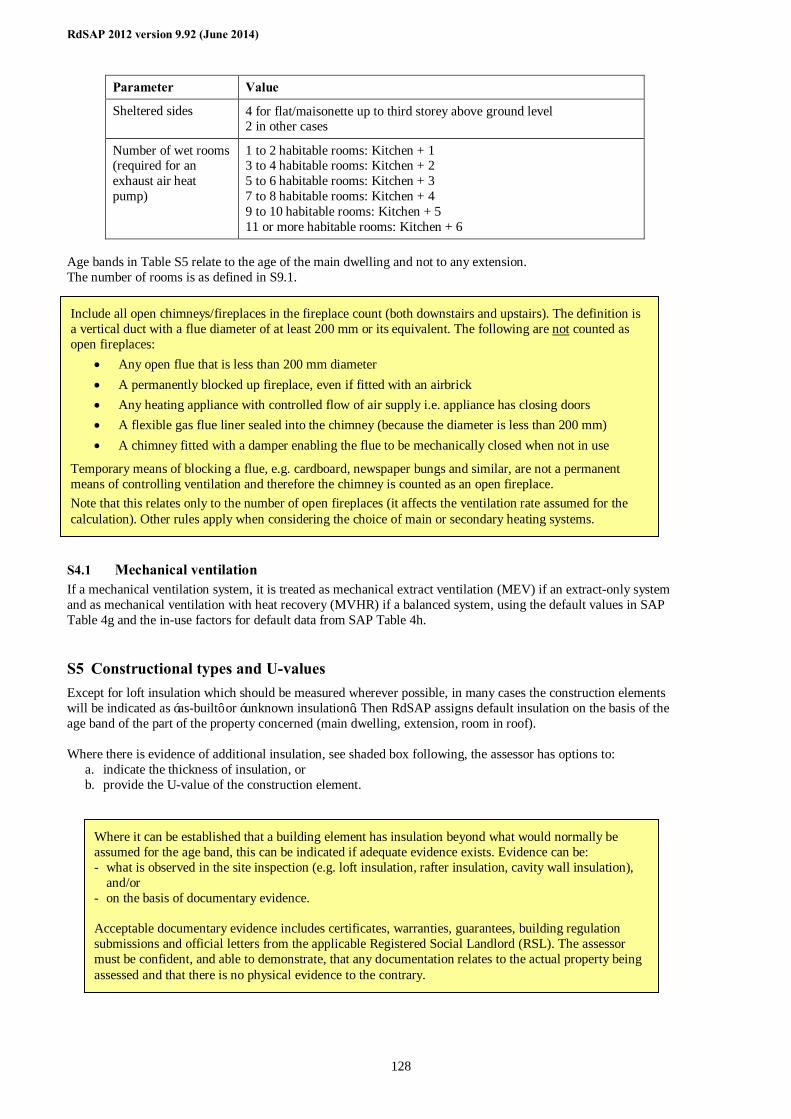
RdSAP 2012 version 9.92 (June 2014)
128
Parameter Value
Sheltered sides 4 for flat/maisonette up to third storey above ground level 2 in other cases
Number of wet rooms (required for an exhaust air heat pump)
1 to 2 habitable rooms: Kitchen + 1 3 to 4 habitable rooms: Kitchen + 2 5 to 6 habitable rooms: Kitchen + 3 7 to 8 habitable rooms: Kitchen + 4 9 to 10 habitable rooms: Kitchen + 5 11 or more habitable rooms: Kitchen + 6
Age bands in Table S5 relate to the age of the main dwelling and not to any extension. The number of rooms is as defined in S9.1.
S4.1 Mechanical ventilation If a mechanical ventilation system, it is treated as mechanical extract ventilation (MEV) if an extract-only system and as mechanical ventilation with heat recovery (MVHR) if a balanced system, using the default values in SAP Table 4g and the in-use factors for default data from SAP Table 4h.
S5 Constructional types and U-values Except for loft insulation which should be measured wherever possible, in many cases the construction elements will be indicated as ‘as-built’ or ‘unknown insulation’. Then RdSAP assigns default insulation on the basis of the age band of the part of the property concerned (main dwelling, extension, room in roof). Where there is evidence of additional insulation, see shaded box following, the assessor has options to:
a. indicate the thickness of insulation, or b. provide the U-value of the construction element.
Include all open chimneys/fireplaces in the fireplace count (both downstairs and upstairs). The definition is a vertical duct with a flue diameter of at least 200 mm or its equivalent. The following are not counted as open fireplaces:
• Any open flue that is less than 200 mm diameter • A permanently blocked up fireplace, even if fitted with an airbrick • Any heating appliance with controlled flow of air supply i.e. appliance has closing doors • A flexible gas flue liner sealed into the chimney (because the diameter is less than 200 mm) • A chimney fitted with a damper enabling the flue to be mechanically closed when not in use
Temporary means of blocking a flue, e.g. cardboard, newspaper bungs and similar, are not a permanent means of controlling ventilation and therefore the chimney is counted as an open fireplace. Note that this relates only to the number of open fireplaces (it affects the ventilation rate assumed for the calculation). Other rules apply when considering the choice of main or secondary heating systems.
Where it can be established that a building element has insulation beyond what would normally be assumed for the age band, this can be indicated if adequate evidence exists. Evidence can be: - what is observed in the site inspection (e.g. loft insulation, rafter insulation, cavity wall insulation),
and/or - on the basis of documentary evidence. Acceptable documentary evidence includes certificates, warranties, guarantees, building regulation submissions and official letters from the applicable Registered Social Landlord (RSL). The assessor must be confident, and able to demonstrate, that any documentation relates to the actual property being assessed and that there is no physical evidence to the contrary.
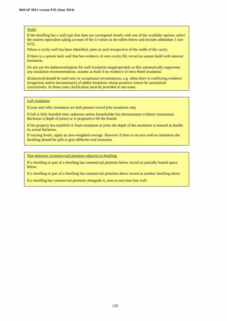
RdSAP 2012 version 9.92 (June 2014)
129
Walls If the dwelling has a wall type that does not correspond closely with one of the available options, select the nearest equivalent taking account of the U-values in the tables below and include addendum 1 (see S15). Where a cavity wall has been identified, enter as such irrespective of the width of the cavity.
If there is a system built wall that has evidence of retro cavity fill, record as system build with internal insulation.
Do not use the ‘unknown’ option for wall insulation inappropriately as this automatically suppresses any insulation recommendation; assume as-built if no evidence of retro-fitted insulation.
‘Unknown’ should be used only in exceptional circumstances, e.g. when there is conflicting evidence (inspection and/or documentary) of added insulation whose presence cannot be ascertained conclusively. In these cases clarification must be provided in site notes.
Loft insulation
If joist and rafter insulation are both present record joist insulation only
If loft is fully boarded enter unknown unless householder has documentary evidence (maximum thickness is depth of joists) or is prepared to lift the boards
If the property has multifoil or foam insulation at joists the depth of the insulation is entered as double its actual thickness. If varying levels, apply an area-weighted average. However if there is an area with no insulation the dwelling should be split to give different roof scenarios.
Non-domestic (commercial) premises adjacent to dwelling
If a dwelling or part of a dwelling has commercial premises below record as partially heated space below.
If a dwelling or part of a dwelling has commercial premises above record as another dwelling above.
If a dwelling has commercial premises alongside it, treat as non-heat loss wall.
RdSAP 2012 version 9.92 (June 2014)
130
Where the assessor has entered the U-value of any construction element that is used directly for the calculations. Otherwise Table S19 indicates the options used for collection of data on site in respect of additional insulation of elements. These are: - floor insulation - cavity filled wall - internal or external wall insulation - party wall insulation (cavity fill) - measured thickness of loft insulation - rafter insulation - flat roof insulation - insulation of roof rooms A U-value is assigned to an insulated loft according to the measured insulation thickness. In other cases the U-value with additional insulation is based on 50, 100 or 150 mm of insulation of the mineral wool type (assume 50 mm if thickness is unknown). U-values of construction elements are determined within software from the constructional type, date of construction and, where applicable, thickness of additional insulation, according to the tables below. U-values are obtained separately for the main part of the dwelling and for any extension. If the insulation status is unknown, the relevant value for ‘as built’ is used.
S5.1 U-values of external walls Unless the U-value is provided by the assessor obtain wall U-values from Table S6, S7 or S8.
Wall types
Where a cavity wall has been identified, enter as such irrespective of the width of the cavity..
If there is a system built wall that has evidence of retro cavity fill, record as system build with internal insulation..
Do not use the ‘unknown’ option for wall insulation inappropriately as this automatically suppresses any insulation recommendation; assume as-built if no evidence of retro-fitted insulation.
‘Unknown’ should be used only in exceptional circumstances, e.g. when there is conflicting evidence (inspection and/or documentary) of added insulation whose presence cannot be ascertained conclusively. In these cases clarification must be provided in site notes.
U-value entry (walls, roofs, floors)
The U-value is that of the whole element, including any added insulation. Documentary evidence applicable to the property being assessed (see convention 9.02) must be provided and recorded if overwriting any default U-value. This evidence shall be either:
- relevant building control approval, which both correctly defines the construction in question and states the calculated U-value; or
- a U-value calculation produced or verified by a suitably qualified person. Evidence of suitable qualification is through membership of a recognised U-value calculation competency scheme (BBA/TIMSA (UK)), OCDEA membership (England & Wales, Northern Ireland) or any other scheme formally agreed between Accreditation Schemes/Approved Organisations and Government.
If insulation is multifoil or foam insulation the thickness is entered as double the actual thickness.
If there is both internal and external wall insulation add the insulation thicknesses together and enter as external.
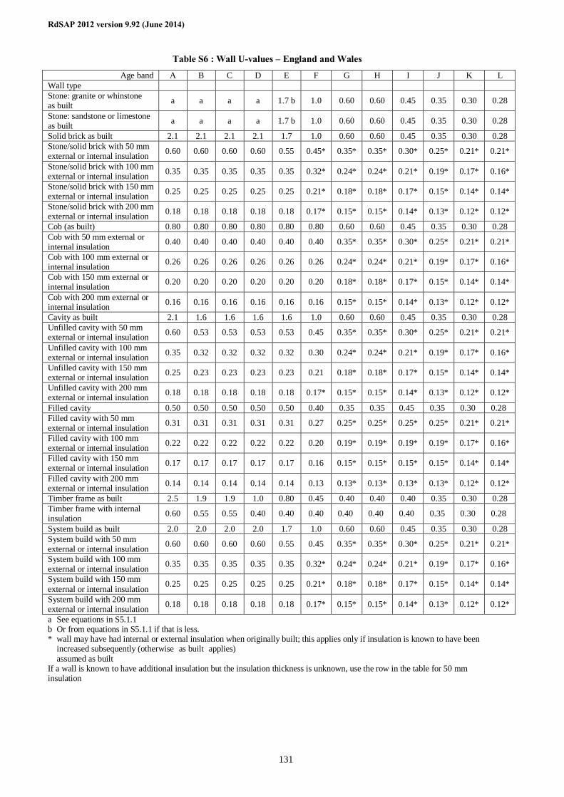
RdSAP 2012 version 9.92 (June 2014)
131
Table S6 : Wall U-values – England and Wales
Age band A B C D E F G H I J K L Wall type Stone: granite or whinstone as built a a a a 1.7 b 1.0 0.60 0.60 0.45 0.35 0.30 0.28
Stone: sandstone or limestone as built a a a a 1.7 b 1.0 0.60 0.60 0.45 0.35 0.30 0.28
Solid brick as built 2.1 2.1 2.1 2.1 1.7 1.0 0.60 0.60 0.45 0.35 0.30 0.28 Stone/solid brick with 50 mm external or internal insulation 0.60 0.60 0.60 0.60 0.55 0.45* 0.35* 0.35* 0.30* 0.25* 0.21* 0.21*
Stone/solid brick with 100 mm external or internal insulation 0.35 0.35 0.35 0.35 0.35 0.32* 0.24* 0.24* 0.21* 0.19* 0.17* 0.16*
Stone/solid brick with 150 mm external or internal insulation 0.25 0.25 0.25 0.25 0.25 0.21* 0.18* 0.18* 0.17* 0.15* 0.14* 0.14*
Stone/solid brick with 200 mm external or internal insulation 0.18 0.18 0.18 0.18 0.18 0.17* 0.15* 0.15* 0.14* 0.13* 0.12* 0.12*
Cob (as built) 0.80 0.80 0.80 0.80 0.80 0.80 0.60 0.60 0.45 0.35 0.30 0.28 Cob with 50 mm external or internal insulation 0.40 0.40 0.40 0.40 0.40 0.40 0.35* 0.35* 0.30* 0.25* 0.21* 0.21*
Cob with 100 mm external or internal insulation 0.26 0.26 0.26 0.26 0.26 0.26 0.24* 0.24* 0.21* 0.19* 0.17* 0.16*
Cob with 150 mm external or internal insulation 0.20 0.20 0.20 0.20 0.20 0.20 0.18* 0.18* 0.17* 0.15* 0.14* 0.14*
Cob with 200 mm external or internal insulation 0.16 0.16 0.16 0.16 0.16 0.16 0.15* 0.15* 0.14* 0.13* 0.12* 0.12*
Cavity as built 2.1 1.6 1.6 1.6 1.6 1.0 0.60 0.60 0.45 0.35 0.30 0.28 Unfilled cavity with 50 mm external or internal insulation 0.60 0.53 0.53 0.53 0.53 0.45 0.35* 0.35* 0.30* 0.25* 0.21* 0.21*
Unfilled cavity with 100 mm external or internal insulation 0.35 0.32 0.32 0.32 0.32 0.30 0.24* 0.24* 0.21* 0.19* 0.17* 0.16*
Unfilled cavity with 150 mm external or internal insulation 0.25 0.23 0.23 0.23 0.23 0.21 0.18* 0.18* 0.17* 0.15* 0.14* 0.14*
Unfilled cavity with 200 mm external or internal insulation 0.18 0.18 0.18 0.18 0.18 0.17* 0.15* 0.15* 0.14* 0.13* 0.12* 0.12*
Filled cavity 0.50 0.50 0.50 0.50 0.50 0.40 0.35 0.35 0.45† 0.35† 0.30† 0.28† Filled cavity with 50 mm external or internal insulation 0.31 0.31 0.31 0.31 0.31 0.27 0.25* 0.25* 0.25* 0.25* 0.21* 0.21*
Filled cavity with 100 mm external or internal insulation 0.22 0.22 0.22 0.22 0.22 0.20 0.19* 0.19* 0.19* 0.19* 0.17* 0.16*
Filled cavity with 150 mm external or internal insulation 0.17 0.17 0.17 0.17 0.17 0.16 0.15* 0.15* 0.15* 0.15* 0.14* 0.14*
Filled cavity with 200 mm external or internal insulation 0.14 0.14 0.14 0.14 0.14 0.13 0.13* 0.13* 0.13* 0.13* 0.12* 0.12*
Timber frame as built 2.5 1.9 1.9 1.0 0.80 0.45 0.40 0.40 0.40 0.35 0.30 0.28 Timber frame with internal insulation 0.60 0.55 0.55 0.40 0.40 0.40 0.40† 0.40† 0.40† 0.35† 0.30† 0.28†
System build as built 2.0 2.0 2.0 2.0 1.7 1.0 0.60 0.60 0.45 0.35 0.30 0.28 System build with 50 mm external or internal insulation 0.60 0.60 0.60 0.60 0.55 0.45 0.35* 0.35* 0.30* 0.25* 0.21* 0.21*
System build with 100 mm external or internal insulation 0.35 0.35 0.35 0.35 0.35 0.32* 0.24* 0.24* 0.21* 0.19* 0.17* 0.16*
System build with 150 mm external or internal insulation 0.25 0.25 0.25 0.25 0.25 0.21* 0.18* 0.18* 0.17* 0.15* 0.14* 0.14*
System build with 200 mm external or internal insulation 0.18 0.18 0.18 0.18 0.18 0.17* 0.15* 0.15* 0.14* 0.13* 0.12* 0.12*
a See equations in S5.1.1 b Or from equations in S5.1.1 if that is less. * wall may have had internal or external insulation when originally built; this applies only if insulation is known to have been
increased subsequently (otherwise ‘as built’ applies) † assumed as built If a wall is known to have additional insulation but the insulation thickness is unknown, use the row in the table for 50 mm insulation
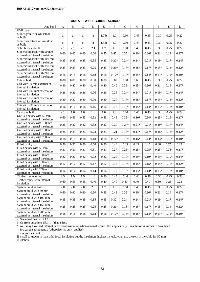
RdSAP 2012 version 9.92 (June 2014)
132
Table S7 : Wall U-values – Scotland
Age band A B C D E F G H I J K L Wall type Stone: granite or whinstone as built a a a a 1.7 b 1.0 0.60 0.45 0.45 0.30 0.25 0.22
Stone: sandstone or limestone as built a a a a 1.5 b 1.0 0.60 0.45 0.45 0.30 0.25 0.22
Solid brick as built 2.1 2.1 2.1 2.1 1.7 1.0 0.60 0.45 0.45 0.30 0.25 0.22 Stone/solid brick with 50 mm external or internal insulation 0.60 0.60 0.60 0.60 0.55 0.45* 0.35* 0.30* 0.30* 0.21* 0.19* 0.17*
Stone/solid brick with 100 mm external or internal insulation 0.35 0.35 0.35 0.35 0.35 0.32* 0.24* 0.24* 0.21* 0.19* 0.17* 0.14*
Stone/solid brick with 150 mm external or internal insulation 0.25 0.25 0.25 0.25 0.25 0.21* 0.18* 0.18* 0.17* 0.15* 0.14* 0.12*
Stone/solid brick with 200 mm external or internal insulation 0.18 0.18 0.18 0.18 0.18 0.17* 0.15* 0.15* 0.14* 0.13* 0.12* 0.10*
Cob as built 0.80 0.80 0.80 0.80 0.80 0.80 0.60 0.60 0.45 0.30 0.25 0.22 Cob with 50 mm external or internal insulation 0.40 0.40 0.40 0.40 0.40 0.40 0.35* 0.35* 0.30* 0.21* 0.19* 0.17*
Cob with 100 mm external or internal insulation 0.26 0.26 0.26 0.26 0.26 0.26 0.24* 0.24* 0.21* 0.19* 0.17* 0.14*
Cob with 150 mm external or internal insulation 0.20 0.20 0.20 0.20 0.20 0.20 0.18* 0.18* 0.17* 0.15* 0.14* 0.12*
Cob with 200 mm external or internal insulation 0.16 0.16 0.16 0.16 0.16 0.16 0.15* 0.15* 0.14* 0.13* 0.12* 0.10*
Cavity as built 2.1 1.6 1.6 1.6 1.6 1.0 0.60 0.45 0.45 0.30 0.25 0.22 Unfilled cavity with 50 mm external or internal insulation 0.60 0.53 0.53 0.53 0.53 0.45 0.35* 0.30* 0.30* 0.25* 0.19* 0.17*
Unfilled cavity with 100 mm external or internal insulation 0.35 0.32 0.32 0.32 0.32 0.30 0.24* 0.21* 0.21* 0.19* 0.17* 0.14*
Unfilled cavity with 150 mm external or internal insulation 0.25 0.23 0.23 0.23 0.23 0.21 0.18* 0.17* 0.17* 0.15* 0.14* 0.12*
Unfilled cavity with 200 mm external or internal insulation 0.18 0.18 0.18 0.18 0.18 0.17* 0.15* 0.15* 0.14* 0.13* 0.12* 0.10*
Filled cavity 0.50 0.50 0.50 0.50 0.50 0.40 0.35 0.45† 0.45† 0.30† 0.25† 0.22† Filled cavity with 50 mm external or internal insulation 0.31 0.31 0.31 0.31 0.31 0.27 0.25* 0.25* 0.25* 0.25* 0.25* 0.17*
Filled cavity with 100 mm external or internal insulation 0.22 0.22 0.22 0.22 0.22 0.20 0.19* 0.19* 0.19* 0.19* 0.19* 0.14*
Filled cavity with 150 mm external or internal insulation 0.17 0.17 0.17 0.17 0.17 0.16 0.15* 0.15* 0.15* 0.15* 0.15* 0.12*
Filled cavity with 200 mm external or internal insulation 0.14 0.14 0.14 0.14 0.14 0.13 0.13* 0.13* 0.13* 0.13* 0.12* 0.10*
Timber frame as built 2.5 1.9 1.9 1.0 0.80 0.45 0.40 0.40 0.40 0.30 0.25 0.22 Timber frame with internal insulation 0.60 0.55 0.55 0.40 0.40 0.40 0.40† 0.40† 0.40† 0.30† 0.25† 0.22†
System build as built 2.0 2.0 2.0 2.0 1.7 1.0 0.60 0.45 0.45 0.30 0.25 0.22 System build with 50 mm external or internal insulation 0.60 0.60 0.60 0.60 0.55 0.45 0.35* 0.30* 0.30* 0.21* 0.19* 0.17*
System build with 100 mm external or internal insulation 0.35 0.35 0.35 0.35 0.35 0.32* 0.24* 0.24* 0.21* 0.19* 0.17* 0.14*
System build with 150 mm external or internal insulation 0.25 0.25 0.25 0.25 0.25 0.21* 0.18* 0.18* 0.17* 0.15* 0.14* 0.12*
System build with 200 mm external or internal insulation 0.18 0.18 0.18 0.18 0.18 0.17* 0.15* 0.15* 0.14* 0.13* 0.12* 0.10*
a See equations in S5.1.1 b Or from equations S5.1.1 if that is less. * wall may have had internal or external insulation when originally built; this applies only if insulation is known to have been
increased subsequently (otherwise ‘as built’ applies) † assumed as built If a wall is known to have additional insulation but the insulation thickness is unknown, use the row in the table for 50 mm insulation
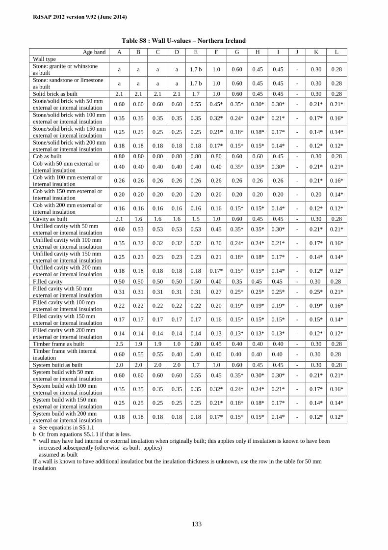
RdSAP 2012 version 9.92 (June 2014)
133
Table S8 : Wall U-values – Northern Ireland
Age band A B C D E F G H I J K L Wall type Stone: granite or whinstone as built a a a a 1.7 b 1.0 0.60 0.45 0.45 - 0.30 0.28
Stone: sandstone or limestone as built a a a a 1.7 b 1.0 0.60 0.45 0.45 - 0.30 0.28
Solid brick as built 2.1 2.1 2.1 2.1 1.7 1.0 0.60 0.45 0.45 - 0.30 0.28 Stone/solid brick with 50 mm external or internal insulation 0.60 0.60 0.60 0.60 0.55 0.45* 0.35* 0.30* 0.30* - 0.21* 0.21*
Stone/solid brick with 100 mm external or internal insulation 0.35 0.35 0.35 0.35 0.35 0.32* 0.24* 0.24* 0.21* - 0.17* 0.16*
Stone/solid brick with 150 mm external or internal insulation 0.25 0.25 0.25 0.25 0.25 0.21* 0.18* 0.18* 0.17* - 0.14* 0.14*
Stone/solid brick with 200 mm external or internal insulation 0.18 0.18 0.18 0.18 0.18 0.17* 0.15* 0.15* 0.14* - 0.12* 0.12*
Cob as built 0.80 0.80 0.80 0.80 0.80 0.80 0.60 0.60 0.45 - 0.30 0.28 Cob with 50 mm external or internal insulation 0.40 0.40 0.40 0.40 0.40 0.40 0.35* 0.35* 0.30* - 0.21* 0.21*
Cob with 100 mm external or internal insulation 0.26 0.26 0.26 0.26 0.26 0.26 0.26 0.26 0.26 - 0.21* 0.16*
Cob with 150 mm external or internal insulation 0.20 0.20 0.20 0.20 0.20 0.20 0.20 0.20 0.20 - 0.20 0.14*
Cob with 200 mm external or internal insulation 0.16 0.16 0.16 0.16 0.16 0.16 0.15* 0.15* 0.14* - 0.12* 0.12*
Cavity as built 2.1 1.6 1.6 1.6 1.5 1.0 0.60 0.45 0.45 - 0.30 0.28 Unfilled cavity with 50 mm external or internal insulation 0.60 0.53 0.53 0.53 0.53 0.45 0.35* 0.35* 0.30* - 0.21* 0.21*
Unfilled cavity with 100 mm external or internal insulation 0.35 0.32 0.32 0.32 0.32 0.30 0.24* 0.24* 0.21* - 0.17* 0.16*
Unfilled cavity with 150 mm external or internal insulation 0.25 0.23 0.23 0.23 0.23 0.21 0.18* 0.18* 0.17* - 0.14* 0.14*
Unfilled cavity with 200 mm external or internal insulation 0.18 0.18 0.18 0.18 0.18 0.17* 0.15* 0.15* 0.14* - 0.12* 0.12*
Filled cavity 0.50 0.50 0.50 0.50 0.50 0.40 0.35 0.45† 0.45† - 0.30† 0.28† Filled cavity with 50 mm external or internal insulation 0.31 0.31 0.31 0.31 0.31 0.27 0.25* 0.25* 0.25* - 0.25* 0.21*
Filled cavity with 100 mm external or internal insulation 0.22 0.22 0.22 0.22 0.22 0.20 0.19* 0.19* 0.19* - 0.19* 0.16*
Filled cavity with 150 mm external or internal insulation 0.17 0.17 0.17 0.17 0.17 0.16 0.15* 0.15* 0.15* - 0.15* 0.14*
Filled cavity with 200 mm external or internal insulation 0.14 0.14 0.14 0.14 0.14 0.13 0.13* 0.13* 0.13* - 0.12* 0.12*
Timber frame as built 2.5 1.9 1.9 1.0 0.80 0.45 0.40 0.40 0.40 - 0.30 0.28 Timber frame with internal insulation 0.60 0.55 0.55 0.40 0.40 0.40 0.40† 0.40† 0.40† - 0.30† 0.28†
System build as built 2.0 2.0 2.0 2.0 1.7 1.0 0.60 0.45 0.45 - 0.30 0.28 System build with 50 mm external or internal insulation 0.60 0.60 0.60 0.60 0.55 0.45 0.35* 0.30* 0.30* - 0.21* 0.21*
System build with 100 mm external or internal insulation 0.35 0.35 0.35 0.35 0.35 0.32* 0.24* 0.24* 0.21* - 0.17* 0.16*
System build with 150 mm external or internal insulation 0.25 0.25 0.25 0.25 0.25 0.21* 0.18* 0.18* 0.17* - 0.14* 0.14*
System build with 200 mm external or internal insulation 0.18 0.18 0.18 0.18 0.18 0.17* 0.15* 0.15* 0.14* - 0.12* 0.12*
a See equations in S5.1.1 b Or from equations S5.1.1 if that is less. * wall may have had internal or external insulation when originally built; this applies only if insulation is known to have been
increased subsequently (otherwise ‘as built’ applies) † assumed as built If a wall is known to have additional insulation but the insulation thickness is unknown, use the row in the table for 50 mm insulation
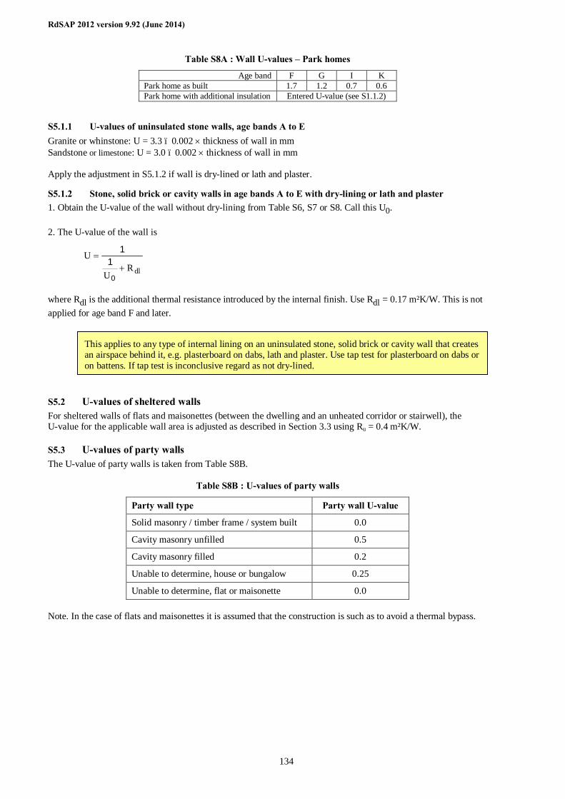
RdSAP 2012 version 9.92 (June 2014)
134
Table S8A : Wall U-values – Park homes
Age band F G I K Park home as built 1.7 1.2 0.7 0.6 Park home with additional insulation Entered U-value (see S1.1.2)
S5.1.1 U-values of uninsulated stone walls, age bands A to E Granite or whinstone: U = 3.3 – 0.002 × thickness of wall in mm Sandstone or limestone: U = 3.0 – 0.002 × thickness of wall in mm Apply the adjustment in S5.1.2 if wall is dry-lined or lath and plaster.
S5.1.2 Stone, solid brick or cavity walls in age bands A to E with dry-lining or lath and plaster 1. Obtain the U-value of the wall without dry-lining from Table S6, S7 or S8. Call this U0. 2. The U-value of the wall is
dlRU
U+
=
0
11
where Rdl is the additional thermal resistance introduced by the internal finish. Use Rdl = 0.17 m²K/W. This is not applied for age band F and later.
S5.2 U-values of sheltered walls For sheltered walls of flats and maisonettes (between the dwelling and an unheated corridor or stairwell), the U-value for the applicable wall area is adjusted as described in Section 3.3 using Ru = 0.4 m²K/W.
S5.3 U-values of party walls The U-value of party walls is taken from Table S8B.
Table S8B : U-values of party walls
Party wall type Party wall U-value
Solid masonry / timber frame / system built 0.0
Cavity masonry unfilled 0.5
Cavity masonry filled 0.2
Unable to determine, house or bungalow 0.25
Unable to determine, flat or maisonette 0.0 Note. In the case of flats and maisonettes it is assumed that the construction is such as to avoid a thermal bypass.
This applies to any type of internal lining on an uninsulated stone, solid brick or cavity wall that creates an airspace behind it, e.g. plasterboard on dabs, lath and plaster. Use tap test for plasterboard on dabs or on battens. If tap test is inconclusive regard as not dry-lined.
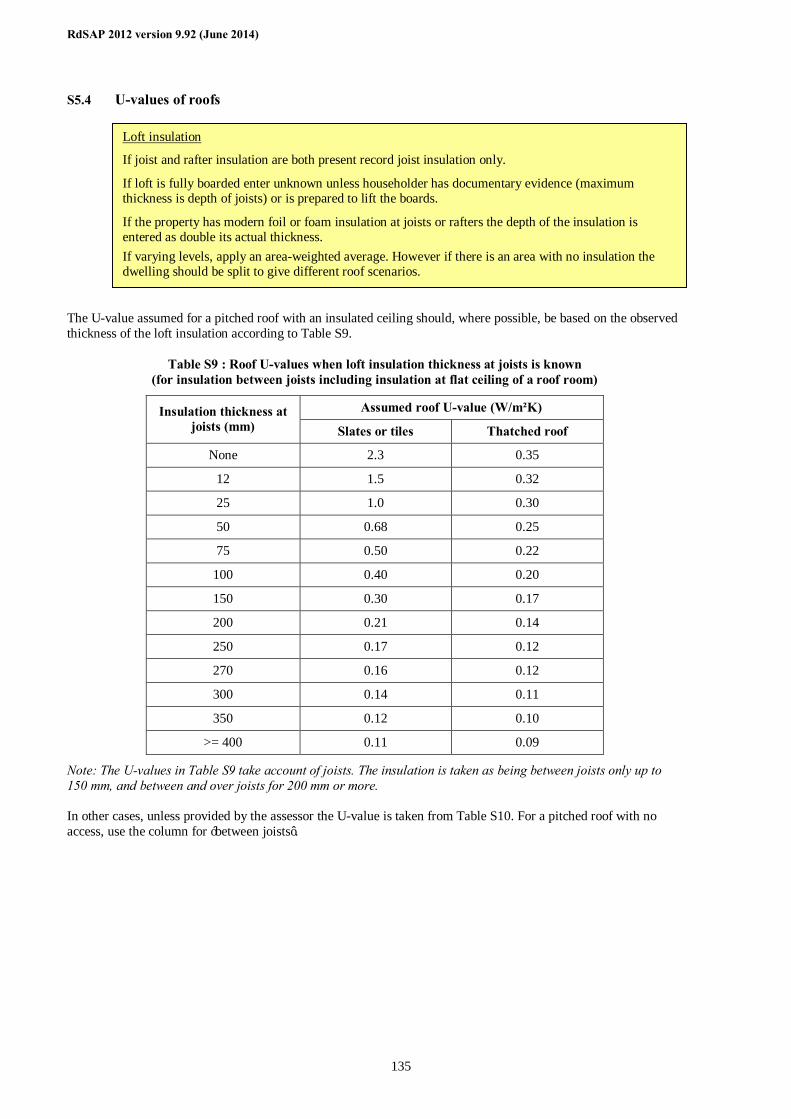
RdSAP 2012 version 9.92 (June 2014)
135
S5.4 U-values of roofs The U-value assumed for a pitched roof with an insulated ceiling should, where possible, be based on the observed thickness of the loft insulation according to Table S9.
Table S9 : Roof U-values when loft insulation thickness at joists is known (for insulation between joists including insulation at flat ceiling of a roof room)
Assumed roof U-value (W/m²K) Insulation thickness at joists (mm) Slates or tiles Thatched roof
None 2.3 0.35
12 1.5 0.32
25 1.0 0.30
50 0.68 0.25
75 0.50 0.22
100 0.40 0.20
150 0.30 0.17
200 0.21 0.14
250 0.17 0.12
270 0.16 0.12
300 0.14 0.11
350 0.12 0.10
>= 400 0.11 0.09
Note: The U-values in Table S9 take account of joists. The insulation is taken as being between joists only up to 150 mm, and between and over joists for 200 mm or more. In other cases, unless provided by the assessor the U-value is taken from Table S10. For a pitched roof with no access, use the column for ‘between joists’.
Loft insulation
If joist and rafter insulation are both present record joist insulation only.
If loft is fully boarded enter unknown unless householder has documentary evidence (maximum thickness is depth of joists) or is prepared to lift the boards.
If the property has modern foil or foam insulation at joists or rafters the depth of the insulation is entered as double its actual thickness. If varying levels, apply an area-weighted average. However if there is an area with no insulation the dwelling should be split to give different roof scenarios.
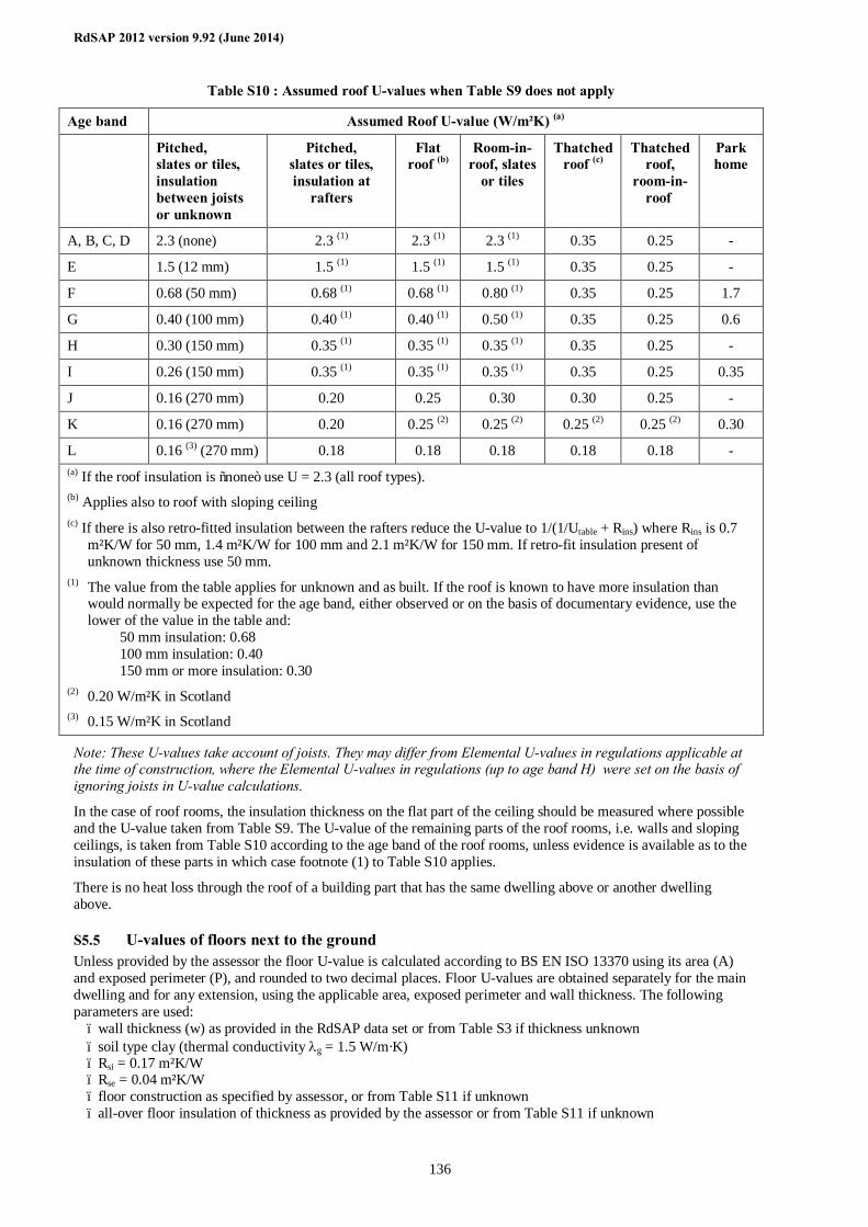
RdSAP 2012 version 9.92 (June 2014)
136
Table S10 : Assumed roof U-values when Table S9 does not apply
Age band Assumed Roof U-value (W/m²K) (a)
Pitched, slates or tiles, insulation between joists or unknown
Pitched, slates or tiles, insulation at
rafters
Flat roof (b)
Room-in-roof, slates
or tiles
Thatched roof (c)
Thatched roof,
room-in-roof
Park home
A, B, C, D 2.3 (none) 2.3 (1) 2.3 (1) 2.3 (1) 0.35 0.25 -
E 1.5 (12 mm) 1.5 (1) 1.5 (1) 1.5 (1) 0.35 0.25 -
F 0.68 (50 mm) 0.68 (1) 0.68 (1) 0.80 (1) 0.35 0.25 1.7
G 0.40 (100 mm) 0.40 (1) 0.40 (1) 0.50 (1) 0.35 0.25 0.6
H 0.30 (150 mm) 0.35 (1) 0.35 (1) 0.35 (1) 0.35 0.25 -
I 0.26 (150 mm) 0.35 (1) 0.35 (1) 0.35 (1) 0.35 0.25 0.35
J 0.16 (270 mm) 0.20 0.25 0.30 0.30 0.25 -
K 0.16 (270 mm) 0.20 0.25 (2) 0.25 (2) 0.25 (2) 0.25 (2) 0.30
L 0.16 (3) (270 mm) 0.18 0.18 0.18 0.18 0.18 - (a) If the roof insulation is “none” use U = 2.3 (all roof types). (b) Applies also to roof with sloping ceiling (c) If there is also retro-fitted insulation between the rafters reduce the U-value to 1/(1/Utable + Rins) where Rins is 0.7
m²K/W for 50 mm, 1.4 m²K/W for 100 mm and 2.1 m²K/W for 150 mm. If retro-fit insulation present of unknown thickness use 50 mm.
(1) The value from the table applies for unknown and as built. If the roof is known to have more insulation than would normally be expected for the age band, either observed or on the basis of documentary evidence, use the lower of the value in the table and: 50 mm insulation: 0.68 100 mm insulation: 0.40 150 mm or more insulation: 0.30
(2) 0.20 W/m²K in Scotland (3) 0.15 W/m²K in Scotland
Note: These U-values take account of joists. They may differ from Elemental U-values in regulations applicable at the time of construction, where the Elemental U-values in regulations (up to age band H) were set on the basis of ignoring joists in U-value calculations.
In the case of roof rooms, the insulation thickness on the flat part of the ceiling should be measured where possible and the U-value taken from Table S9. The U-value of the remaining parts of the roof rooms, i.e. walls and sloping ceilings, is taken from Table S10 according to the age band of the roof rooms, unless evidence is available as to the insulation of these parts in which case footnote (1) to Table S10 applies.
There is no heat loss through the roof of a building part that has the same dwelling above or another dwelling above.
S5.5 U-values of floors next to the ground Unless provided by the assessor the floor U-value is calculated according to BS EN ISO 13370 using its area (A) and exposed perimeter (P), and rounded to two decimal places. Floor U-values are obtained separately for the main dwelling and for any extension, using the applicable area, exposed perimeter and wall thickness. The following parameters are used:
– wall thickness (w) as provided in the RdSAP data set or from Table S3 if thickness unknown – soil type clay (thermal conductivity λg = 1.5 W/m·K) – Rsi = 0.17 m²K/W – Rse = 0.04 m²K/W – floor construction as specified by assessor, or from Table S11 if unknown – all-over floor insulation of thickness as provided by the assessor or from Table S11 if unknown
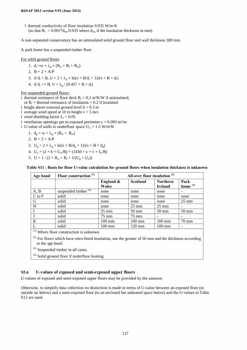
RdSAP 2012 version 9.92 (June 2014)
137
– thermal conductivity of floor insulation 0.035 W/m·K (so that Rf = 0.001*dins/0.035 where dins if the insulation thickness in mm)
A non-separated conservatory has an uninsulated solid ground floor and wall thickness 300 mm. A park home has a suspended timber floor. For solid ground floors
1. dt =w + λg × (Rsi + Rf + Rse) 2. B = 2 × A/P 3. if dt < B, U = 2 × λg × ln(π × B/dt + 1)/(π × B + dt) 4. if dt >= B, U = λg / (0.457 × B + dt)
For suspended ground floors: – thermal resistance of floor deck Rf = 0.2 m²K/W if uninsulated, or Rf = thermal resistance of insulation + 0.2 if insulated – height above external ground level h = 0.3 m – average wind speed at 10 m height v = 5 m/s – wind shielding factor fw = 0.05 – ventilation openings per m exposed perimeter ε = 0.003 m²/m – U-value of walls to underfloor space Uw = 1.5 W/m²K
1. dg = w + λg × (Rsi + Rse) 2. B = 2 × A/P 3. Ug = 2 × λg × ln(π × B/dg + 1)/(π × B + dg) 4. Ux = (2 × h × Uw/B) + (1450 × ε × v × fw/B) 5. U = 1 / (2 × Rsi + Rf + 1/(Ug + Ux))
Table S11 : Basis for floor U-value calculation for ground floors when insulation thickness is unknown
Age band Floor construction (1) All-over floor insulation (2) England &
Wales Scotland Northern
Ireland Park home (3)
A, B suspended timber (4) none none none - C to F solid none none none none G solid none none none 25 mm H solid none 25 mm 25 mm - I solid 25 mm 50 mm 50 mm 50 mm J solid 75 mm 75 mm - - K solid 100 mm 100 mm 100 mm 70 mm L solid 100 mm 120 mm 100 mm - (1) Where floor construction is unknown (2) For floors which have retro-fitted insulation, use the greater of 50 mm and the thickness according
to the age band. (3) Suspended timber in all cases. (4) Solid ground floor if underfloor heating.
S5.6 U-values of exposed and semi-exposed upper floors U-values of exposed and semi-exposed upper floors may be provided by the assessor. Otherwise, to simplify data collection no distinction is made in terms of U-value between an exposed floor (to outside air below) and a semi-exposed floor (to an enclosed but unheated space below) and the U-values in Table S12 are used.
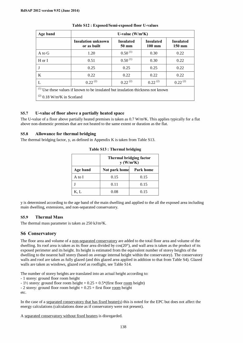
RdSAP 2012 version 9.92 (June 2014)
138
Table S12 : Exposed/Semi-exposed floor U-values
Age band U-value (W/m²K)
Insulation unknown or as built
Insulated 50 mm
Insulated 100 mm
Insulated 150 mm
A to G 1.20 0.50 (1) 0.30 0.22
H or I 0.51 0.50 (1) 0.30 0.22
J 0.25 0.25 0.25 0.22
K 0.22 0.22 0.22 0.22
L 0.22 (2) 0.22 (2) 0.22 (2) 0.22 (2) (1) Use these values if known to be insulated but insulation thickness not known (2) 0.18 W/m²K in Scotland
S5.7 U-value of floor above a partially heated space The U-value of a floor above partially heated premises is taken as 0.7 W/m²K. This applies typically for a flat above non-domestic premises that are not heated to the same extent or duration as the flat.
S5.8 Allowance for thermal bridging The thermal bridging factor, y, as defined in Appendix K is taken from Table S13.
Table S13 : Thermal bridging
Thermal bridging factor y (W/m²K)
Age band Not park home Park home
A to I 0.15 0.15
J 0.11 0.15
K, L 0.08 0.15 y is determined according to the age band of the main dwelling and applied to the all the exposed area including main dwelling, extensions, and non-separated conservatory.
S5.9 Thermal Mass The thermal mass parameter is taken as 250 kJ/m²K.
S6 Conservatory The floor area and volume of a non-separated conservatory are added to the total floor area and volume of the dwelling. Its roof area is taken as its floor area divided by cos(20°), and wall area is taken as the product of its exposed perimeter and its height. Its height is estimated from the equivalent number of storey heights of the dwelling to the nearest half storey (based on average internal height within the conservatory). The conservatory walls and roof are taken as fully glazed (and this glazed area applied in addition to that from Table S4). Glazed walls are taken as windows, glazed roof as rooflight, see Table S14. The number of storey heights are translated into an actual height according to: - 1 storey: ground floor room height - 1½ storey: ground floor room height + 0.25 + 0.5*(first floor room height) - 2 storey: ground floor room height + 0.25 + first floor room height etc. In the case of a separated conservatory that has fixed heater(s) this is noted for the EPC but does not affect the energy calculations (calculations done as if conservatory were not present). A separated conservatory without fixed heaters is disregarded.
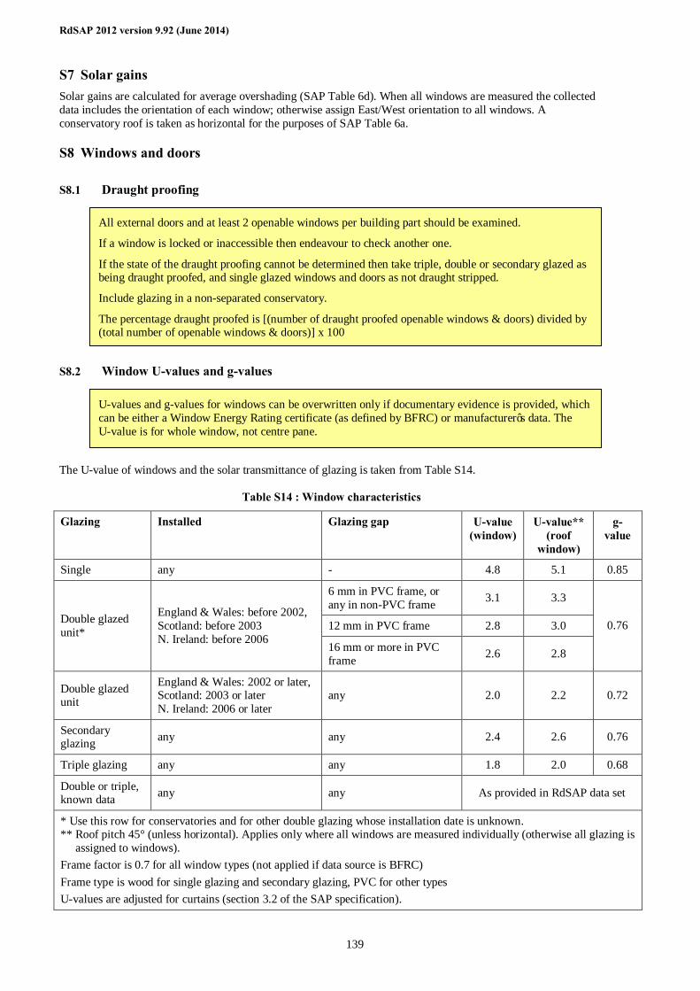
RdSAP 2012 version 9.92 (June 2014)
139
S7 Solar gains Solar gains are calculated for average overshading (SAP Table 6d). When all windows are measured the collected data includes the orientation of each window; otherwise assign East/West orientation to all windows. A conservatory roof is taken as horizontal for the purposes of SAP Table 6a.
S8 Windows and doors
S8.1 Draught proofing
S8.2 Window U-values and g-values The U-value of windows and the solar transmittance of glazing is taken from Table S14.
Table S14 : Window characteristics
Glazing Installed Glazing gap U-value (window)
U-value** (roof
window)
g-value
Single any - 4.8 5.1 0.85
6 mm in PVC frame, or any in non-PVC frame 3.1 3.3
12 mm in PVC frame 2.8 3.0 Double glazed unit*
England & Wales: before 2002, Scotland: before 2003 N. Ireland: before 2006
16 mm or more in PVC frame 2.6 2.8
0.76
Double glazed unit
England & Wales: 2002 or later, Scotland: 2003 or later N. Ireland: 2006 or later
any 2.0 2.2 0.72
Secondary glazing any any 2.4 2.6 0.76
Triple glazing any any 1.8 2.0 0.68
Double or triple, known data any any As provided in RdSAP data set
* Use this row for conservatories and for other double glazing whose installation date is unknown. ** Roof pitch 45° (unless horizontal). Applies only where all windows are measured individually (otherwise all glazing is
assigned to windows). Frame factor is 0.7 for all window types (not applied if data source is BFRC) Frame type is wood for single glazing and secondary glazing, PVC for other types U-values are adjusted for curtains (section 3.2 of the SAP specification).
U-values and g-values for windows can be overwritten only if documentary evidence is provided, which can be either a Window Energy Rating certificate (as defined by BFRC) or manufacturer’s data. The U-value is for whole window, not centre pane.
All external doors and at least 2 openable windows per building part should be examined.
If a window is locked or inaccessible then endeavour to check another one.
If the state of the draught proofing cannot be determined then take triple, double or secondary glazed as being draught proofed, and single glazed windows and doors as not draught stripped.
Include glazing in a non-separated conservatory.
The percentage draught proofed is [(number of draught proofed openable windows & doors) divided by (total number of openable windows & doors)] x 100
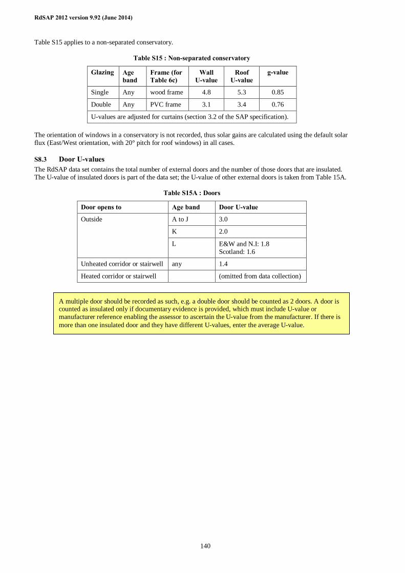
RdSAP 2012 version 9.92 (June 2014)
140
Table S15 applies to a non-separated conservatory.
Table S15 : Non-separated conservatory
Glazing Age band
Frame (for Table 6c)
Wall U-value
Roof U-value
g-value
Single Any wood frame 4.8 5.3 0.85
Double Any PVC frame 3.1 3.4 0.76
U-values are adjusted for curtains (section 3.2 of the SAP specification). The orientation of windows in a conservatory is not recorded, thus solar gains are calculated using the default solar flux (East/West orientation, with 20° pitch for roof windows) in all cases.
S8.3 Door U-values The RdSAP data set contains the total number of external doors and the number of those doors that are insulated. The U-value of insulated doors is part of the data set; the U-value of other external doors is taken from Table 15A.
Table S15A : Doors
Door opens to Age band Door U-value
A to J 3.0
K 2.0
Outside
L E&W and N.I: 1.8 Scotland: 1.6
Unheated corridor or stairwell any 1.4
Heated corridor or stairwell (omitted from data collection)
A multiple door should be recorded as such, e.g. a double door should be counted as 2 doors. A door is counted as insulated only if documentary evidence is provided, which must include U-value or manufacturer reference enabling the assessor to ascertain the U-value from the manufacturer. If there is more than one insulated door and they have different U-values, enter the average U-value.
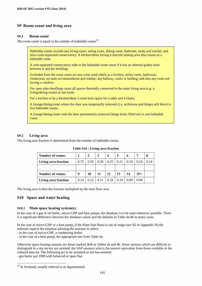
RdSAP 2012 version 9.92 (June 2014)
141
S9 Room count and living area
S9.1 Room count The room count is equal to the number of habitable rooms28.
S9.2 Living area The living area fraction is determined from the number of habitable rooms.
Table S16 : Living area fraction
Number of rooms: 1 2 3 4 5 6 7 8
Living area fraction: 0.75 0.50 0.30 0.25 0.21 0.18 0.16 0.14
Number of rooms: 9 10 11 12 13 14 15+
Living area fraction: 0.13 0.12 0.11 0.10 0.10 0.09 0.09 The living area is then the fraction multiplied by the total floor area.
S10 Space and water heating
S10.1 Main space heating system(s) In the case of a gas or oil boiler, micro-CHP and heat pumps, the database is to be used whenever possible. There is a significant difference between the database values and the defaults in Table 4a/4b in many cases. In the case of micro-CHP or a heat pump, if the Plant Size Ratio is out of range (see N2 in Appendix N) the software reports the situation advising the assessor to select: - in the case of micro-CHP, a condensing boiler; - in the case of a heat pump, the appropriate one from Table 4a. Otherwise space heating systems are those marked “rd” in Tables 4a and 4b. Some systems which are difficult to distinguish in a site survey are omitted; the SAP assessor selects the nearest equivalent from those available in the reduced data set. The following are to be assumed as not fan-assisted: - gas boiler pre 1998 with balanced or open flue
28 In Scotland, usually referred to as ‘apartments’.
Habitable rooms include any living room, sitting room, dining room, bedroom, study and similar; and also a non-separated conservatory. A kitchen/diner having a discrete seating area also counts as a habitable room.
A non-separated conservatory adds to the habitable room count if it has an internal quality door between it and the dwelling.
Excluded from the room count are any room used solely as a kitchen, utility room, bathroom, cloakroom, en-suite accommodation and similar; any hallway, stairs or landing; and also any room not having a window.
For open plan dwellings count all spaces thermally connected to the main living area (e.g. a living/dining room) as one room.
For a kitchen to be a kitchen/diner it must have space for a table and 4 chairs.
A lounge/dining room where the door was temporarily removed (i.e. architrave and hinges still there) is two habitable rooms.
A lounge/dining room with the door permanently removed (hinge holes filled etc) is one habitable room.

RdSAP 2012 version 9.92 (June 2014)
142
- oil boiler - gas warm air, balanced or open flue The following fuels apply only for boilers from the database:
Biogas biodiesel from any biomass source biodiesel from vegetable oil only appliances able to use mineral oil or liquid biofuel
Where no space heating system is present, the calculation is done for portable electric heaters (with no controls) in all habitable rooms. The control type for this case (as is needed for SAP Table 9) is 2, the same as for portable electric heaters with no controls. For treatment of unheated habitable rooms see A4 in Appendix A.
If one heating system feeds both underfloor and radiators, enter radiators. This is because if radiators are present a higher flow temperature is assumed (unless flow temperature is known to be low).
If electric storage heaters are present as main heating but single meter, enter as electric panel heaters and include addendum 6 (see S15). If the storage heaters are fan-assisted suppress the recommendation for fan-assisted storage heaters.
If boiler/heating system is present but not working (or condemned) it should still be entered as the main heating system. However if boiler is not present enter no heating system even though a boiler is intended.
A community heating system is one that serves more than one dwelling. Select the actual fuel used by the community system where that can be ascertained; if it cannot be, select mains gas.
If the dwelling has a micro-CHP system that cannot be located in the database enter as a condensing boiler and include addendum 5 (see S15).
RdSAP 2012 version 9.92 (June 2014)
143
If there are two main heating systems then: - the two systems are taken as heating different parts of the dwelling; - the assessor estimates the percentage of the total heated floor area served by system 2; - the fraction of main heat from system 2 is 0.01 times the percentage.
S10.2 Space heating controls Space heating controls are those marked “rd” in Table 4e. Some control features whose effect is small are omitted.
S10.3 Secondary heating
Include a secondary heater if there is a fixed emitter present regardless of whether the main heating system(s) heat all rooms.
If more than one secondary heater: (a) select the device that heats greatest number of habitable rooms; (b) if that does not resolve it, select the device using the cheapest fuel; (c) if that does not resolve it, select the device with the lowest efficiency.
Electric focal point fires are included even if not wired by fixed spur.
An open fireplace is to be considered in the heating assessment if capable of supporting an open fire, even if no fuel is present. The fuel to be specified is smokeless fuel in smoke control areas and dual fuel outside smoke control areas. Open fires in bedrooms are disregarded when identifying the heating systems (main and secondary) and heated habitable room count. They are counted in the number of open chimneys, if appropriate.
Solid Fuels If the appliance can burn only one fuel, specify that fuel (includes exempted appliances burning wood in Smoke Control Areas). Otherwise:
Smoke control area: Open fire - smokeless fuel; closed heater - anthracite Not smoke control area: Open fire - dual fuel; closed heater - wood logs if capable otherwise anthracite.
Two main systems
There is an option for two main systems to cover the situation of different systems heating different parts of the dwelling.
If main system 1 heats all habitable rooms, there is no main system 2 unless it serves DHW only (see S10.4).
Main systems 1 and 2 cannot be room heaters except in the case of the dwelling’s heating consisting solely of room heaters.
A main system is generally one that would be described as central heating (a heat generator providing heat to several rooms via a heat distribution system), although the term does also include, for example, storage heaters and fixed direct-acting heaters in each room.
When there are two main systems, system 1 always heats the living area and: - where two systems serve different spaces, the percentage recorded for each system is in
proportion to the heated floor area served by each system; - where two systems serve the same heating circuit the default assumption is a 50/50 split. A
different ratio can be used only if there is clear documentary evidence to back it up.
When there are two main systems and a recommendation is made for heating system upgrade, include addendum 9.
A second main system is not to be confused with a secondary heater. The latter are room heater(s) heating individual room(s) either as a supplement to the main heating in the room (e.g. a wood burning stove in the main room) or for rooms not heated by the main system(s). See section S10.3 for rules on secondary heaters.
If there is more than one main system within a room, select one of them according to the rules in SAP Appendix A and disregard the other.
Integrated storage/direct acting in living area, normal storage heating elsewhere: treat as two main systems.
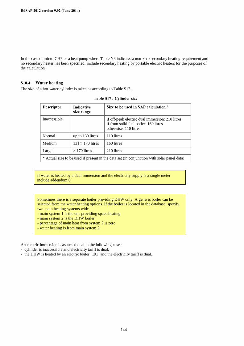
RdSAP 2012 version 9.92 (June 2014)
144
In the case of micro-CHP or a heat pump where Table N8 indicates a non-zero secondary heating requirement and no secondary heater has been specified, include secondary heating by portable electric heaters for the purposes of the calculation.
S10.4 Water heating The size of a hot-water cylinder is taken as according to Table S17.
Table S17 : Cylinder size
Descriptor Indicative size range
Size to be used in SAP calculation *
Inaccessible if off-peak electric dual immersion: 210 litres if from solid fuel boiler: 160 litres otherwise: 110 litres
Normal up to 130 litres 110 litres
Medium 131 – 170 litres 160 litres
Large > 170 litres 210 litres
* Actual size to be used if present in the data set (in conjunction with solar panel data) An electric immersion is assumed dual in the following cases: - cylinder is inaccessible and electricity tariff is dual; - the DHW is heated by an electric boiler (191) and the electricity tariff is dual.
If water is heated by a dual immersion and the electricity supply is a single meter include addendum 6.
Sometimes there is a separate boiler providing DHW only. A generic boiler can be selected from the water heating options. If the boiler is located in the database, specify two main heating systems with: - main system 1 is the one providing space heating - main system 2 is the DHW boiler - percentage of main heat from system 2 is zero - water heating is from main system 2.
RdSAP 2012 version 9.92 (June 2014)
145
S10.5 Back boilers For the purposes of the calculation the appropriate fire or room heater is substituted. In the case of a gas fire with back boiler, the efficiency of the fire is from the room heater section of Table 4a according to the type of fire and the efficiency of the back boiler is 65% (from water heating section of Table 4a). In the case of oil or solid fuel, the efficiency from the room heater section of Table 4a is applied to both the fire/room heater and the boiler.
S10.6 No water heating system Where no water heating system is present, the calculation is done for an electric immersion heater. If the electric meter is dual the immersion heater is also dual, but is a single immersion otherwise (including unknown meter). The calculation is done for a cylinder defined by the first row of Table S17 and the first row of Table S18.
S10.7 Solar water heating
S10.8 Flue gas heat recovery Calculation according to SAP Appendix G.
S10.9 Waste water heat recovery Calculation according to SAP Appendix G.
S10.10 Space and water heating assumptions Parameters not included in the data collection (Table S19) are defined in Table S18.
Where water heating is from a back boiler or room heater with boiler, and the boiler provides water heating only, the appropriate fire or room heater is identified in the data collection process, and the water heating is identified as from main system or from secondary system.
Where the back boiler provides space heating: - if gas, the back boiler is selected as main heating, the associated fire is selected as the
secondary heating, and the water heating is from main system. - if oil or solid fuel, the combination of room heater and boiler is selected as main
heating and the water heating is from main system.
Include flue gas heat recovery only if found in the database, identified in same way as for heating systems. When the model cannot be found no default option is available but the presence of the device should be recorded in site notes.
Include waste water heat recovery only if found in the database. When the model cannot be found no default option is available but the presence of the device should be recorded in site notes.
For instantaneous systems, number of rooms with bath and/or shower includes rooms with only an electric shower. If two showers found in a room, count as one.
Only mixer showers count for instantaneous waste water heat recovery. Mixer shower means a shower where the hot water is provided by a boiler (combi or regular), heat pump or immersion heater. A mixer shower attached to bath taps is recorded as a mixer shower only if there is a permanent bracket over the bath and there is a shower curtain or screen.
Documentary evidence is required to over-write collector or solar store values except that orientation, tilt and overshading can be overwritten with visual evidence.
If the panel/collector details are available but the solar store information is not, the default values can be used for the solar store. If the solar store is combined and details are being recorded the volume of the combined cylinder must also be recorded.
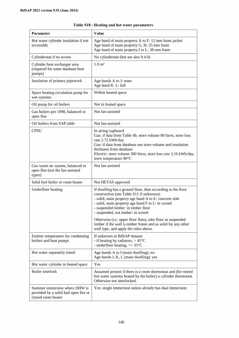
RdSAP 2012 version 9.92 (June 2014)
146
Table S18 : Heating and hot water parameters
Parameter Value
Hot water cylinder insulation if not accessible
Age band of main property A to F: 12 mm loose jacket Age band of main property G, H: 25 mm foam Age band of main property I to L: 38 mm foam
Cylinderstat if no access No cylinderstat (but see also 9.4.9)
Cylinder heat exchanger area (required for some database heat pumps)
1.0 m²
Insulation of primary pipework Age bands A to J: none Age band K. L: full
Space heating circulation pump for wet systems
Within heated space
Oil pump for oil boilers Not in heated space
Gas boilers pre 1998, balanced or open flue
Not fan-assisted
Oil boilers from SAP table Not fan-assisted
CPSU In airing cupboard Gas: if data from Table 4b, store volume 80 litres, store loss rate 2.72 kWh/day Gas: if data from database use store volume and insulation thickness from database Electric: store volume 300 litres, store loss rate 3.16 kWh/day, store temperature 90°C
Gas warm air system, balanced or open flue (not the fan-assisted types)
Not fan assisted
Solid fuel boiler or room heater Not HETAS approved
Underfloor heating If dwelling has a ground floor, then according to the floor construction (see Table S11 if unknown): - solid, main property age band A to E: concrete slab - solid, main property age band F to L: in screed - suspended timber: in timber floor - suspended, not timber: in screed
Otherwise (i.e. upper floor flats), take floor as suspended timber if the wall is timber frame and as solid for any other wall type, and apply the rules above.
Emitter temperature for condensing boilers and heat pumps
If unknown in RdSAP dataset: - if heating by radiators, > 45°C - underfloor heating, <= 35°C
Hot water separately timed Age bands A to I (main dwelling): no Age bands J, K, L (main dwelling): yes
Hot water cylinder in heated space Yes
Boiler interlock Assumed present if there is a room thermostat and (for stored hot water systems heated by the boiler) a cylinder thermostat. Otherwise not interlocked.
Summer immersion where DHW is provided by a solid fuel open fire or closed room heater
Yes; single immersion unless already has dual immersion
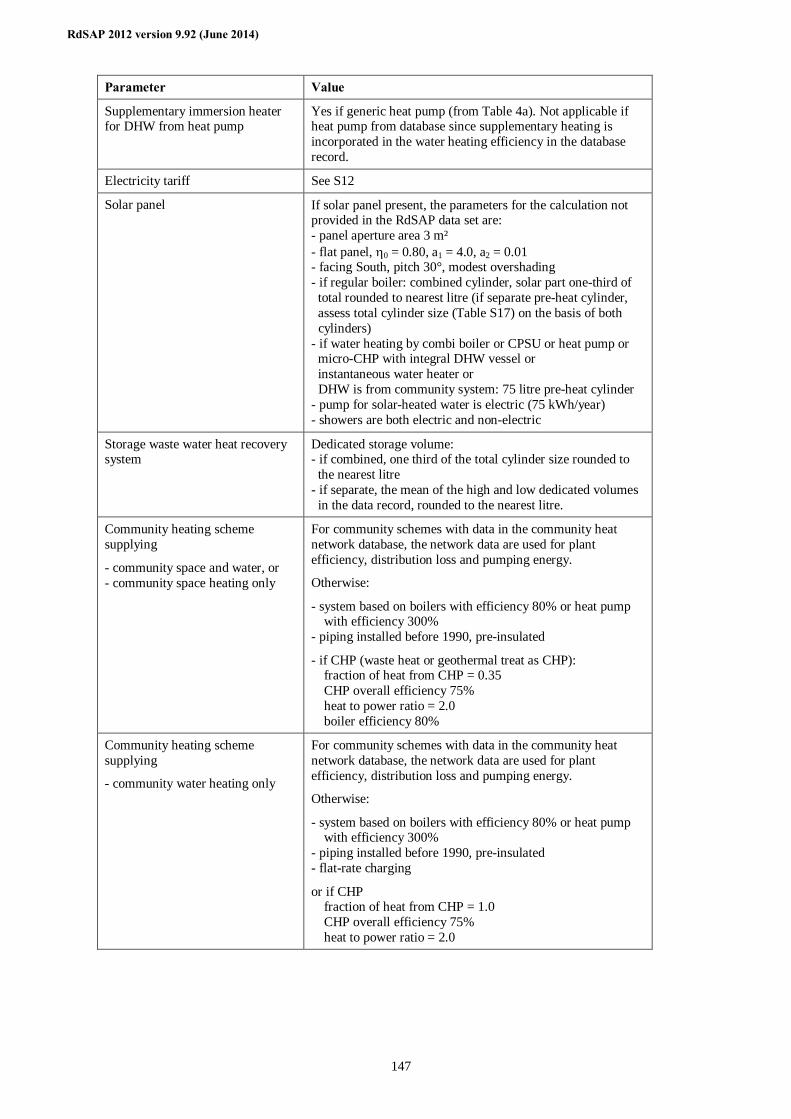
RdSAP 2012 version 9.92 (June 2014)
147
Parameter Value
Supplementary immersion heater for DHW from heat pump
Yes if generic heat pump (from Table 4a). Not applicable if heat pump from database since supplementary heating is incorporated in the water heating efficiency in the database record.
Electricity tariff See S12
Solar panel If solar panel present, the parameters for the calculation not provided in the RdSAP data set are: - panel aperture area 3 m² - flat panel, η0 = 0.80, a1 = 4.0, a2 = 0.01 - facing South, pitch 30°, modest overshading - if regular boiler: combined cylinder, solar part one-third of total rounded to nearest litre (if separate pre-heat cylinder, assess total cylinder size (Table S17) on the basis of both cylinders) - if water heating by combi boiler or CPSU or heat pump or micro-CHP with integral DHW vessel or instantaneous water heater or DHW is from community system: 75 litre pre-heat cylinder - pump for solar-heated water is electric (75 kWh/year) - showers are both electric and non-electric
Storage waste water heat recovery system
Dedicated storage volume: - if combined, one third of the total cylinder size rounded to the nearest litre - if separate, the mean of the high and low dedicated volumes in the data record, rounded to the nearest litre.
Community heating scheme supplying
- community space and water, or - community space heating only
For community schemes with data in the community heat network database, the network data are used for plant efficiency, distribution loss and pumping energy.
Otherwise:
- system based on boilers with efficiency 80% or heat pump with efficiency 300% - piping installed before 1990, pre-insulated
- if CHP (waste heat or geothermal treat as CHP): fraction of heat from CHP = 0.35 CHP overall efficiency 75% heat to power ratio = 2.0 boiler efficiency 80%
Community heating scheme supplying
- community water heating only
For community schemes with data in the community heat network database, the network data are used for plant efficiency, distribution loss and pumping energy.
Otherwise:
- system based on boilers with efficiency 80% or heat pump with efficiency 300% - piping installed before 1990, pre-insulated - flat-rate charging
or if CHP fraction of heat from CHP = 1.0 CHP overall efficiency 75% heat to power ratio = 2.0
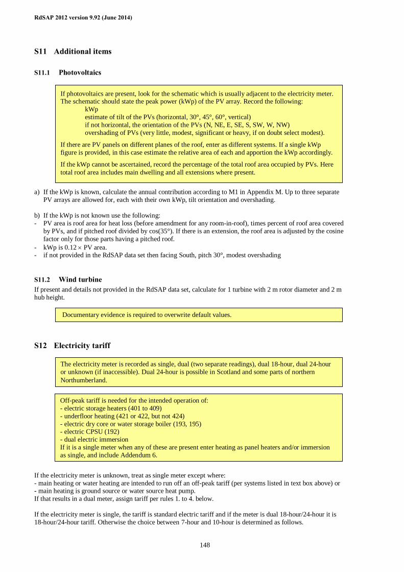
RdSAP 2012 version 9.92 (June 2014)
148
S11 Additional items
S11.1 Photovoltaics a) If the kWp is known, calculate the annual contribution according to M1 in Appendix M. Up to three separate
PV arrays are allowed for, each with their own kWp, tilt orientation and overshading. b) If the kWp is not known use the following: - PV area is roof area for heat loss (before amendment for any room-in-roof), times percent of roof area covered
by PVs, and if pitched roof divided by cos(35°). If there is an extension, the roof area is adjusted by the cosine factor only for those parts having a pitched roof.
- kWp is 0.12 × PV area. - if not provided in the RdSAP data set then facing South, pitch 30°, modest overshading
S11.2 Wind turbine If present and details not provided in the RdSAP data set, calculate for 1 turbine with 2 m rotor diameter and 2 m hub height.
S12 Electricity tariff If the electricity meter is unknown, treat as single meter except where: - main heating or water heating are intended to run off an off-peak tariff (per systems listed in text box above) or - main heating is ground source or water source heat pump. If that results in a dual meter, assign tariff per rules 1. to 4. below. If the electricity meter is single, the tariff is standard electric tariff and if the meter is dual 18-hour/24-hour it is 18-hour/24-hour tariff. Otherwise the choice between 7-hour and 10-hour is determined as follows.
The electricity meter is recorded as single, dual (two separate readings), dual 18-hour, dual 24-hour or unknown (if inaccessible). Dual 24-hour is possible in Scotland and some parts of northern Northumberland.
If photovoltaics are present, look for the schematic which is usually adjacent to the electricity meter. The schematic should state the peak power (kWp) of the PV array. Record the following: kWp estimate of tilt of the PVs (horizontal, 30°, 45°, 60°, vertical) if not horizontal, the orientation of the PVs (N, NE, E, SE, S, SW, W, NW) overshading of PVs (very little, modest, significant or heavy, if on doubt select modest).
If there are PV panels on different planes of the roof, enter as different systems. If a single kWp figure is provided, in this case estimate the relative area of each and apportion the kWp accordingly.
If the kWp cannot be ascertained, record the percentage of the total roof area occupied by PVs. Here total roof area includes main dwelling and all extensions where present.
Off-peak tariff is needed for the intended operation of: - electric storage heaters (401 to 409) - underfloor heating (421 or 422, but not 424) - electric dry core or water storage boiler (193, 195) - electric CPSU (192) - dual electric immersion If it is a single meter when any of these are present enter heating as panel heaters and/or immersion as single, and include Addendum 6.
Documentary evidence is required to overwrite default values.
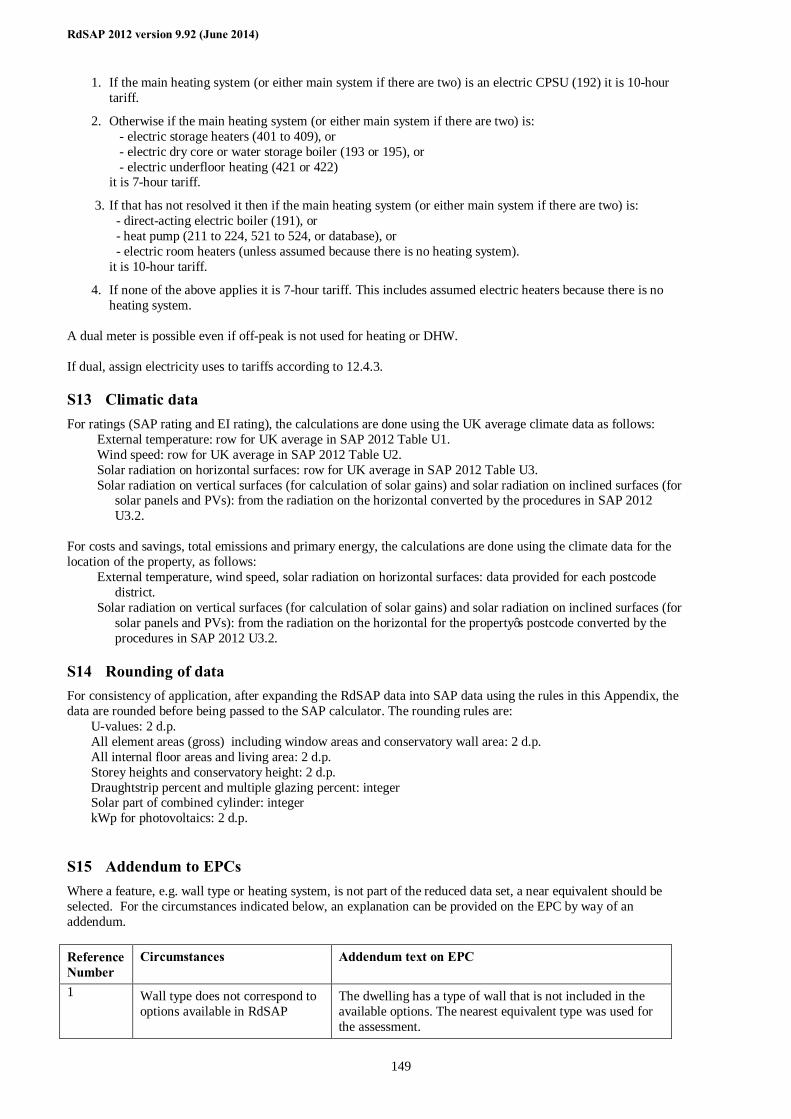
RdSAP 2012 version 9.92 (June 2014)
149
1. If the main heating system (or either main system if there are two) is an electric CPSU (192) it is 10-hour tariff.
2. Otherwise if the main heating system (or either main system if there are two) is: - electric storage heaters (401 to 409), or - electric dry core or water storage boiler (193 or 195), or - electric underfloor heating (421 or 422) it is 7-hour tariff.
3. If that has not resolved it then if the main heating system (or either main system if there are two) is: - direct-acting electric boiler (191), or - heat pump (211 to 224, 521 to 524, or database), or - electric room heaters (unless assumed because there is no heating system). it is 10-hour tariff.
4. If none of the above applies it is 7-hour tariff. This includes assumed electric heaters because there is no heating system.
A dual meter is possible even if off-peak is not used for heating or DHW. If dual, assign electricity uses to tariffs according to 12.4.3.
S13 Climatic data For ratings (SAP rating and EI rating), the calculations are done using the UK average climate data as follows:
External temperature: row for UK average in SAP 2012 Table U1. Wind speed: row for UK average in SAP 2012 Table U2. Solar radiation on horizontal surfaces: row for UK average in SAP 2012 Table U3. Solar radiation on vertical surfaces (for calculation of solar gains) and solar radiation on inclined surfaces (for
solar panels and PVs): from the radiation on the horizontal converted by the procedures in SAP 2012 U3.2.
For costs and savings, total emissions and primary energy, the calculations are done using the climate data for the location of the property, as follows:
External temperature, wind speed, solar radiation on horizontal surfaces: data provided for each postcode district.
Solar radiation on vertical surfaces (for calculation of solar gains) and solar radiation on inclined surfaces (for solar panels and PVs): from the radiation on the horizontal for the property’s postcode converted by the procedures in SAP 2012 U3.2.
S14 Rounding of data For consistency of application, after expanding the RdSAP data into SAP data using the rules in this Appendix, the data are rounded before being passed to the SAP calculator. The rounding rules are:
U-values: 2 d.p. All element areas (gross) including window areas and conservatory wall area: 2 d.p. All internal floor areas and living area: 2 d.p. Storey heights and conservatory height: 2 d.p. Draughtstrip percent and multiple glazing percent: integer Solar part of combined cylinder: integer kWp for photovoltaics: 2 d.p.
S15 Addendum to EPCs Where a feature, e.g. wall type or heating system, is not part of the reduced data set, a near equivalent should be selected. For the circumstances indicated below, an explanation can be provided on the EPC by way of an addendum. Reference Number
Circumstances Addendum text on EPC
1 Wall type does not correspond to options available in RdSAP
The dwelling has a type of wall that is not included in the available options. The nearest equivalent type was used for the assessment.
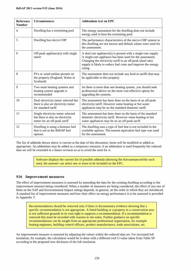
RdSAP 2012 version 9.92 (June 2014)
150
Reference Number
Circumstances Addendum text on EPC
4 Dwelling has a swimming pool The energy assessment for the dwelling does not include energy used to heat the swimming pool.
5 Dwelling has micro-CHP The performance characteristics of the micro-CHP system in this dwelling are not known and default values were used for the assessment.
6 Off-peak appliance(s) with single meter
A dual rate appliance(s) is present with a single-rate supply. A single-rate appliance has been used for the assessment. Changing the electricity tariff to an off-peak (dual rate) supply is likely to reduce fuel costs and improve the energy rating.
8 PVs or wind turbine present on the property (England, Wales or Scotland)
The assessment does not include any feed-in tariffs that may be applicable to this property.
9 Two main heating systems and heating system upgrade is recommended
As there is more than one heating system, you should seek professional advice on the most cost-effective option for upgrading the systems.
10 Dual electricity meter selected but there is also an electricity meter for standard tariff
The assessment has been done on the basis of an off-peak electricity tariff. However some heating or hot water appliances may be on the standard domestic tariff.
11 Single electricity meter selected but there is also an electricity meter for an off-peak tariff
The assessment has been done on the basis of the standard domestic electricity tariff. However some heating or hot water appliances may be on an off-peak tariff.
12 Dwelling is using a biomass fuel that is not in the RdSAP fuel options
The dwelling uses a type of fuel that is not included in the available options. The nearest equivalent fuel type was used for the assessment.
The list of addenda shown above is current at the date of this document; items will be modified or added as appropriate. An addendum may be added as a temporary measure; if an addendum is used frequently the reduced data set will be extended in a future revision so as to avoid the need for it.
S16 Improvement measures The effect of improvement measures is assessed by amending the data for the existing dwelling according to the improvement measure being considered. When a number of measures are being considered, the effect of any one of them on the SAP and Environmental Impact ratings depends, in general, on the order in which they are introduced. A standard list of improvement measures and how their effect on energy performance is to be assessed is provided in Appendix T. An improvement measure is assessed by adjusting the values within the reduced data set. For increased loft insulation, for example, the calculation would be re-done with a different roof U-value taken from Table S9 according to the proposed new thickness of the loft insulation.
Recommendations should be removed only if there is documentary evidence showing that a specific recommendation is not appropriate. A listed building or a property in a conservation area is not sufficient grounds in its own right to suppress a recommendation. If a recommendation is removed this must be recorded with reasons in site notes. Further guidance on specific recommendations can be sought from an appropriate professional organisation, for example heating engineers, building control officers, product manufacturers, trade associations, etc.
Software displays the current list of possible addenda (showing the ‘circumstances’ for each one); the assessor can select one or more to be included on the EPC.
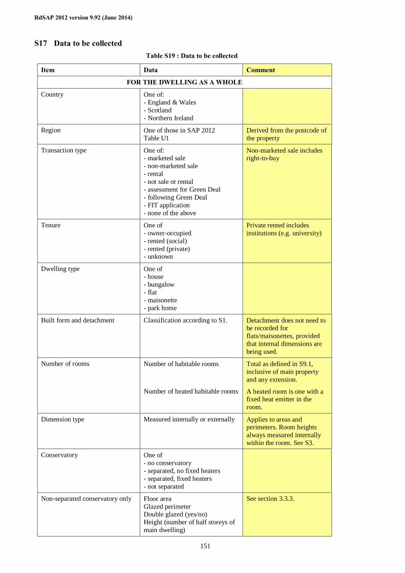
RdSAP 2012 version 9.92 (June 2014)
151
S17 Data to be collected Table S19 : Data to be collected
Item Data Comment
FOR THE DWELLING AS A WHOLE
Country One of: - England & Wales - Scotland - Northern Ireland
Region One of those in SAP 2012 Table U1
Derived from the postcode of the property
Transaction type One of: - marketed sale - non-marketed sale - rental - not sale or rental - assessment for Green Deal - following Green Deal - FIT application - none of the above
Non-marketed sale includes right-to-buy
Tenure One of - owner-occupied - rented (social) - rented (private) - unknown
Private rented includes institutions (e.g. university)
Dwelling type One of - house - bungalow - flat - maisonette - park home
Built form and detachment Classification according to S1. Detachment does not need to be recorded for flats/maisonettes, provided that internal dimensions are being used.
Number of rooms Number of habitable rooms
Number of heated habitable rooms
Total as defined in S9.1, inclusive of main property and any extension.
A heated room is one with a fixed heat emitter in the room.
Dimension type Measured internally or externally Applies to areas and perimeters. Room heights always measured internally within the room. See S3.
Conservatory One of - no conservatory - separated, no fixed heaters - separated, fixed heaters - not separated
Non-separated conservatory only Floor area Glazed perimeter Double glazed (yes/no) Height (number of half storeys of main dwelling)
See section 3.3.3.
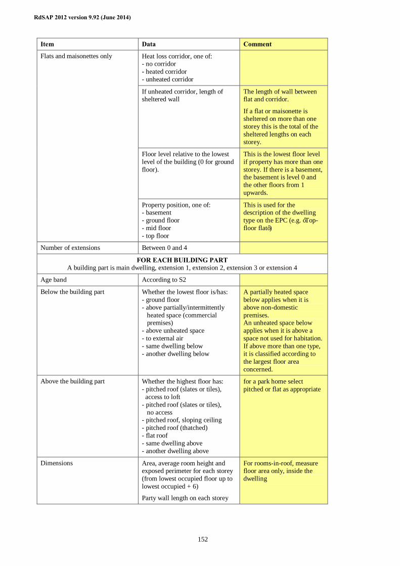
RdSAP 2012 version 9.92 (June 2014)
152
Item Data Comment
Heat loss corridor, one of: - no corridor - heated corridor - unheated corridor
If unheated corridor, length of sheltered wall
The length of wall between flat and corridor.
If a flat or maisonette is sheltered on more than one storey this is the total of the sheltered lengths on each storey.
Floor level relative to the lowest level of the building (0 for ground floor).
This is the lowest floor level if property has more than one storey. If there is a basement, the basement is level 0 and the other floors from 1 upwards.
Flats and maisonettes only
Property position, one of: - basement - ground floor - mid floor - top floor
This is used for the description of the dwelling type on the EPC (e.g. ‘Top-floor flat’)
Number of extensions Between 0 and 4
FOR EACH BUILDING PART A building part is main dwelling, extension 1, extension 2, extension 3 or extension 4
Age band According to S2
Below the building part Whether the lowest floor is/has: - ground floor - above partially/intermittently heated space (commercial premises) - above unheated space - to external air - same dwelling below - another dwelling below
A partially heated space below applies when it is above non-domestic premises. An unheated space below applies when it is above a space not used for habitation. If above more than one type, it is classified according to the largest floor area concerned.
Above the building part Whether the highest floor has: - pitched roof (slates or tiles), access to loft - pitched roof (slates or tiles), no access - pitched roof, sloping ceiling - pitched roof (thatched) - flat roof - same dwelling above - another dwelling above
for a park home select pitched or flat as appropriate
Dimensions Area, average room height and exposed perimeter for each storey (from lowest occupied floor up to lowest occupied + 6)
Party wall length on each storey
For rooms-in-roof, measure floor area only, inside the dwelling
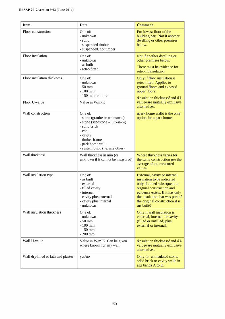
RdSAP 2012 version 9.92 (June 2014)
153
Item Data Comment
Floor construction One of: - unknown - solid - suspended timber - suspended, not timber
For lowest floor of the building part. Not if another dwelling or other premises below.
Floor insulation One of: - unknown - as built - retro-fitted
Not if another dwelling or other premises below.
There must be evidence for retro-fit insulation
Floor insulation thickness One of: - unknown - 50 mm - 100 mm - 150 mm or more
Floor U-value Value in W/m²K
Only if floor insulation is retro-fitted. Applies to ground floors and exposed upper floors.
‘Insulation thickness’ and ‘U-value’ are mutually exclusive alternatives.
Wall construction One of: - stone (granite or whinstone) - stone (sandstone or limestone) - solid brick - cob - cavity - timber frame - park home wall - system build (i.e. any other)
“park home wall” is the only option for a park home.
Wall thickness Wall thickness in mm (or unknown if it cannot be measured)
Where thickness varies for the same construction use the average of the measured values.
Wall insulation type One of: - as built - external - filled cavity - internal - cavity plus external - cavity plus internal - unknown
External, cavity or internal insulation to be indicated only if added subsequent to original construction and evidence exists. If it has only the insulation that was part of the original construction it is ‘as built’.
Wall insulation thickness One of: - unknown - 50 mm - 100 mm - 150 mm - 200 mm
Only if wall insulation is external, internal, or cavity (filled or unfilled) plus external or internal.
Wall U-value Value in W/m²K. Can be given where known for any wall.
‘Insulation thickness’ and ‘U-value’ are mutually exclusive alternatives.
Wall dry-lined or lath and plaster yes/no Only for uninsulated stone, solid brick or cavity walls in age bands A to E..
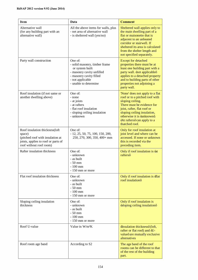
RdSAP 2012 version 9.92 (June 2014)
154
Item Data Comment
Alternative wall (for any building part with an alternative wall)
All the above items for walls, plus - net area of alternative wall - is sheltered wall (yes/no)
Sheltered wall applies only to the main dwelling part of a flat or maisonette that is adjacent to an unheated corridor or stairwell. If sheltered its area is calculated from the shelter length and not specified separately.
Party wall construction One of: - solid masonry, timber frame or system built - masonry cavity unfilled - masonry cavity filled - not applicable - unable to determine
Except for detached properties there must be at least one building part with a party wall. ‘not applicable’ applies to a detached property and to building parts of other properties not adjoining a party wall.
Roof insulation (if not same or another dwelling above)
One of: - none - at joists - at rafters - flat roof insulation - sloping ceiling insulation - unknown
'None' does not apply to a flat roof or to a pitched roof with sloping ceiling. There must be evidence for joist, rafter, flat roof or sloping ceiling insulation, otherwise it is ‘unknown’. ‘At rafters’ can apply to a thatched roof.
Roof insulation thickness(loft space) (pitched roof with insulation at joists, applies to roof or parts of roof without roof room)
One of: - 12, 25, 50, 75, 100, 150, 200, 250, 270, 300, 350, 400+ mm
Only for roof insulation at joist level and where can be accessed. If none or unknown this is recorded via the preceding item.
Rafter insulation thickness One of: - unknown - as built - 50 mm - 100 mm - 150 mm or more
Only if roof insulation is ‘at rafters’
Flat roof insulation thickness One of: - unknown - as built - 50 mm - 100 mm - 150 mm or more
Only if roof insulation is ‘flat roof insulation’
Sloping ceiling insulation thickness
One of: - unknown - as built - 50 mm - 100 mm - 150 mm or more
Only if roof insulation is ‘sloping ceiling insulation’
Roof U-value Value in W/m²K ‘Insulation thickness’ (loft, rafter or flat roof) and ‘U-value’ are mutually exclusive alternatives
Roof room age band According to S2 The age band of the roof rooms can be different to that of the rest of the building part.
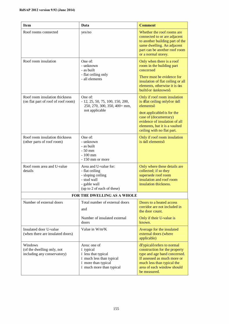
RdSAP 2012 version 9.92 (June 2014)
155
Item Data Comment
Roof rooms connected yes/no Whether the roof rooms are connected to or are adjacent to another building part of the same dwelling. An adjacent part can be another roof room or a normal storey.
Roof room insulation One of: - unknown - as built - flat ceiling only - all elements
Only when there is a roof room in the building part concerned
There must be evidence for insulation of flat ceiling or all elements, otherwise it is ‘as built’ or ‘unknown’.
Roof room insulation thickness (on flat part of roof of roof room)
One of: - 12, 25, 50, 75, 100, 150, 200, 250, 270, 300, 350, 400+ mm, not applicable
Only if roof room insulation is ‘flat ceiling only’ or ‘all elements’
‘not applicable’ is for the case of (documentary) evidence of insulation of all elements, but it is a vaulted ceiling with no flat part.
Roof room insulation thickness (other parts of roof room)
One of: - unknown - as built - 50 mm - 100 mm - 150 mm or more
Only if roof room insulation is ‘all elements’
Roof room area and U-value details
Area and U-value for: - flat ceiling - sloping ceiling - stud wall - gable wall (up to 2 of each of these)
Only where these details are collected; if so they supersede roof room insulation and roof room insulation thickness.
FOR THE DWELLING AS A WHOLE
Number of external doors Total number of external doors
and Number of insulated external doors
Doors to a heated access corridor are not included in the door count.
Only if their U-value is known.
Insulated door U-value (when there are insulated doors)
Value in W/m²K Average for the insulated external doors (where applicable)
Windows (of the dwelling only, not including any conservatory)
Area: one of – typical – less that typical – much less than typical – more than typical – much more than typical
‘Typical’ refers to normal construction for the property type and age band concerned. If assessed as much more or much less than typical the area of each window should be measured.
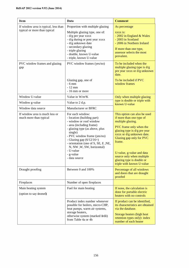
RdSAP 2012 version 9.92 (June 2014)
156
Item Data Comment
If window area is typical, less than typical or more than typical
Proportion with multiple glazing
Multiple glazing type, one of: - d/g pre year xxxx - d/g during or post year xxxx - d/g unknown date - secondary glazing - triple glazing - double, known U-value - triple, known U-value
As percentage
xxxx is: - 2002 in England & Wales - 2003 in Scotland - 2006 in Northern Ireland
If more than one type, assessor selects the most prevalent.
PVC window frames and glazing gap
PVC window frames (yes/no)
Glazing gap, one of - 6 mm - 12 mm - 16 mm or more
To be included when the multiple glazing type is d/g pre year xxxx or d/g unknown date.
To be included if PVC window frames
Window U-value Value in W/m²K
Window g-value Value to 2 d.p.
Window data source Manufacturer or BFRC
Only when multiple glazing type is double or triple with known U-value
If window area is much less or much more than typical
For each window: - location (building part) - window or roof window - area (including frame) - glazing type (as above, plus
single) - PVC window frame (yes/no) - Glazing gap (6/12/16+) - orientation (one of S, SE, E ,NE,
N, NW ,W, SW, horizontal) - U-value - g-value - data source
This option can also be used if more than one type of multiple glazing.
PVC frame only when the glazing type is d/g pre year xxxx or d/g unknown date. Glazing gap only for PVC frame.
U-value, g-value and data source only when multiple glazing type is double or triple with known U-value
Draught proofing Between 0 and 100% Percentage of all windows and doors that are draught proofed
Fireplaces Number of open fireplaces
Fuel for main heating If none, the calculation is done for portable electric heaters with no controls
Main heating system
(option to say ‘none’)
Product index number whenever possible for boilers, micro-CHP, heat pumps, warm air systems, storage heaters, otherwise system (marked “rd”) from Table 4a or 4b
If product can be identified, its characteristics are obtained via the database.
Storage heaters (high heat retention types only): index number of each heater
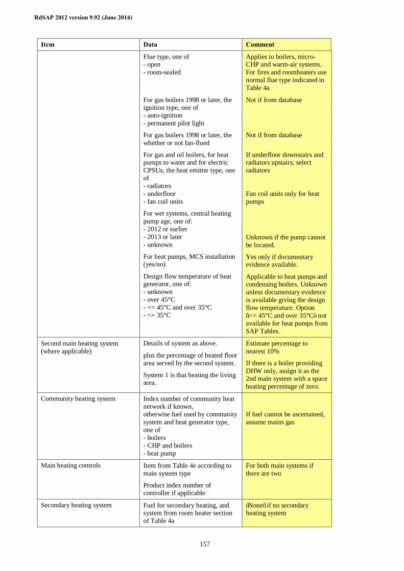
RdSAP 2012 version 9.92 (June 2014)
157
Item Data Comment
Flue type, one of - open - room-sealed
For gas boilers 1998 or later, the ignition type, one of - auto-ignition - permanent pilot light
For gas boilers 1998 or later, the whether or not fan-flued
For gas and oil boilers, for heat pumps to water and for electric CPSUs, the heat emitter type, one of - radiators - underfloor - fan coil units
For wet systems, central heating pump age, one of: - 2012 or earlier - 2013 or later - unknown
For heat pumps, MCS installation (yes/no)
Design flow temperature of heat generator, one of: - unknown - over 45°C - <= 45°C and over 35°C - <= 35°C
Applies to boilers, micro-CHP and warm-air systems. For fires and roomheaters use normal flue type indicated in Table 4a
Not if from database
Not if from database
If underfloor downstairs and radiators upstairs, select radiators Fan coil units only for heat pumps
Unknown if the pump cannot be located.
Yes only if documentary evidence available.
Applicable to heat pumps and condensing boilers. Unknown unless documentary evidence is available giving the design flow temperature. Option “<= 45°C and over 35°C” not available for heat pumps from SAP Tables.
Second main heating system (where applicable)
Details of system as above.
plus the percentage of heated floor area served by the second system.
System 1 is that heating the living area.
Estimate percentage to nearest 10%
If there is a boiler providing DHW only, assign it as the 2nd main system with a space heating percentage of zero.
Community heating system Index number of community heat network if known, otherwise fuel used by community system and heat generator type, one of - boilers - CHP and boilers - heat pump
If fuel cannot be ascertained, assume mains gas
Main heating controls Item from Table 4e according to main system type
Product index number of controller if applicable
For both main systems if there are two
Secondary heating system Fuel for secondary heating, and system from room heater section of Table 4a
‘None’ if no secondary heating system
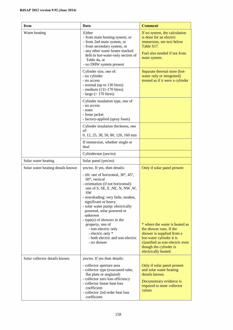
RdSAP 2012 version 9.92 (June 2014)
158
Item Data Comment
Either - from main heating system, or - from 2nd main system, or - from secondary system, or - any other water heater marked “rd” in hot-water-only section of Table 4a, or - no DHW system present
If no system, the calculation is done for an electric immersion, see text below Table S17.
Fuel also needed if not from main system.
Cylinder size, one of: - no cylinder - no access - normal (up to 130 litres) - medium (131-170 litres) - large (> 170 litres)
Separate thermal store (hot-water only or integrated) treated as if it were a cylinder
Cylinder insulation type, one of - no access - none - loose jacket - factory-applied (spray foam)
Cylinder insulation thickness, one of: 0, 12, 25, 38, 50, 80, 120, 160 mm
If immersion, whether single or dual
Water heating
Cylinderstat (yes/no)
Solar water heating Solar panel (yes/no)
Solar water heating details known yes/no. If yes, then details:
- tilt: one of horizontal, 30°, 45°, 60°, vertical - orientation (if not horizontal): one of S, SE, E ,NE, N, NW ,W, SW - overshading: very little, modest, significant or heavy - solar water pump: electrically powered, solar powered or unknown - type(s) of showers in the property, one of - non-electric only - electric only * - both electric and non-electric - no shower
Only if solar panel present
* where the water is heated as the shower runs. If the shower is supplied from a hot-water cylinder it is classified as non-electric even though the cylinder is electrically heated.
Solar collector details known yes/no. If yes then details:
- collector aperture area - collector type (evacuated tube, flat plate or unglazed) - collector zero loss efficiency - collector linear heat loss coefficient - collector 2nd order heat loss coefficient
Only if solar panel present and solar water heating details known.
Documentary evidence is required to enter collector values
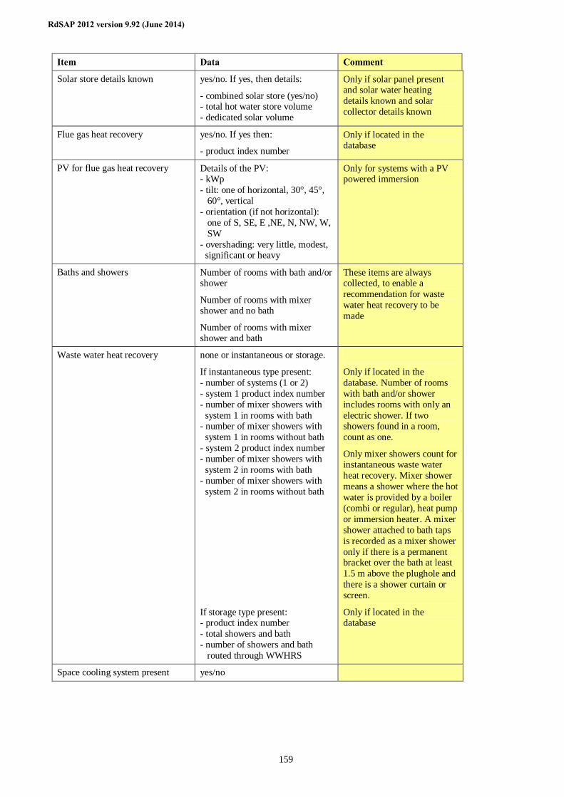
RdSAP 2012 version 9.92 (June 2014)
159
Item Data Comment
Solar store details known yes/no. If yes, then details:
- combined solar store (yes/no) - total hot water store volume - dedicated solar volume
Only if solar panel present and solar water heating details known and solar collector details known
Flue gas heat recovery yes/no. If yes then:
- product index number
Only if located in the database
PV for flue gas heat recovery Details of the PV: - kWp - tilt: one of horizontal, 30°, 45°, 60°, vertical - orientation (if not horizontal): one of S, SE, E ,NE, N, NW, W, SW - overshading: very little, modest, significant or heavy
Only for systems with a PV powered immersion
Baths and showers Number of rooms with bath and/or shower
Number of rooms with mixer shower and no bath
Number of rooms with mixer shower and bath
These items are always collected, to enable a recommendation for waste water heat recovery to be made
Waste water heat recovery none or instantaneous or storage.
If instantaneous type present: - number of systems (1 or 2) - system 1 product index number - number of mixer showers with system 1 in rooms with bath - number of mixer showers with system 1 in rooms without bath - system 2 product index number - number of mixer showers with system 2 in rooms with bath - number of mixer showers with system 2 in rooms without bath
If storage type present: - product index number - total showers and bath - number of showers and bath routed through WWHRS
Only if located in the database. Number of rooms with bath and/or shower includes rooms with only an electric shower. If two showers found in a room, count as one.
Only mixer showers count for instantaneous waste water heat recovery. Mixer shower means a shower where the hot water is provided by a boiler (combi or regular), heat pump or immersion heater. A mixer shower attached to bath taps is recorded as a mixer shower only if there is a permanent bracket over the bath at least 1.5 m above the plughole and there is a shower curtain or screen.
Only if located in the database
Space cooling system present yes/no
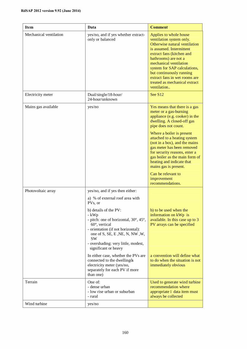
RdSAP 2012 version 9.92 (June 2014)
160
Item Data Comment
Mechanical ventilation yes/no, and if yes whether extract-only or balanced
Applies to whole house ventilation system only. Otherwise natural ventilation is assumed. Intermittent extract fans (kitchen and bathrooms) are not a mechanical ventilation system for SAP calculations, but continuously running extract fans in wet rooms are treated as mechanical extract ventilation..
Electricity meter Dual/single/18-hour/ 24-hour/unknown
See S12
Mains gas available yes/no Yes means that there is a gas meter or a gas-burning appliance (e.g. cooker) in the dwelling. A closed-off gas pipe does not count.
Where a boiler is present attached to a heating system (not in a box), and the mains gas meter has been removed for security reasons, enter a gas boiler as the main form of heating and indicate that mains gas is present.
Can be relevant to improvement recommendations.
Photovoltaic array yes/no, and if yes then either:
a) % of external roof area with PVs, or
b) details of the PV: - kWp - pitch: one of horizontal, 30°, 45°, 60°, vertical - orientation (if not horizontal): one of S, SE, E ,NE, N, NW ,W, SW - overshading: very little, modest, significant or heavy
In either case, whether the PVs are connected to the dwelling’s electricity meter (yes/no, separately for each PV if more than one)
b) to be used when the information on kWp is available. In this case up to 3 PV arrays can be specified
a convention will define what to do when the situation is not immediately obvious
Terrain One of: - dense urban - low rise urban or suburban - rural
Used to generate wind turbine recommendation where appropriate – data item must always be collected
Wind turbine yes/no
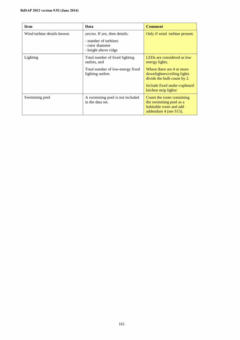
RdSAP 2012 version 9.92 (June 2014)
161
Item Data Comment
Wind turbine details known yes/no. If yes, then details:
- number of turbines - rotor diameter - height above ridge
Only if wind turbine present.
Lighting Total number of fixed lighting outlets, and
Total number of low-energy fixed lighting outlets
LEDs are considered as low energy lights.
Where there are 4 or more downlighters/ceiling lights divide the bulb count by 2.
Include fixed under-cupboard kitchen strip lights/
Swimming pool A swimming pool is not included in the data set.
Count the room containing the swimming pool as a habitable room and add addendum 4 (see S15).
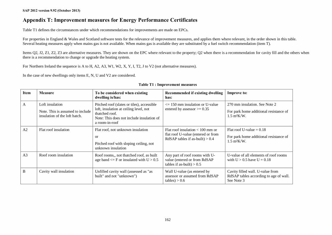
SAP 2012 version 9.92 (October 2013)
162
Appendix T: Improvement measures for Energy Performance Certificates
Table T1 defines the circumstances under which recommendations for improvements are made on EPCs. For properties in England & Wales and Scotland software tests for the relevance of improvement measures, and applies them where relevant, in the order shown in this table. Several heating measures apply when mains gas is not available. When mains gas is available they are substituted by a fuel switch recommendation (item T). Items Q2, J2, Z1, Z2, Z3 are alternative measures. They are shown on the EPC where relevant to the property; Q2 when there is a recommendation for cavity fill and the others when there is a recommendation to change or upgrade the heating system. For Northern Ireland the sequence is A to H, A2, A3, W1, W2, X, Y, I, T2, J to V2 (not alternative measures). In the case of new dwellings only items E, N, U and V2 are considered.
Table T1 : Improvement measures
Item Measure To be considered when existing dwelling is/has:
Recommended if existing dwelling has:
Improve to:
A Loft insulation
Note. This is assumed to include insulation of the loft hatch.
Pitched roof (slates or tiles), accessible loft, insulation at ceiling level, not thatched roof. Note: This does not include insulation of a room-in-roof
<= 150 mm insulation or U-value entered by assessor >= 0.35
270 mm insulation. See Note 2
For park home additional resistance of 1.5 m²K/W.
A2 Flat roof insulation Flat roof, not unknown insulation
or
Pitched roof with sloping ceiling, not unknown insulation
Flat roof insulation < 100 mm or flat roof U-value (entered or from RdSAP tables if as-built) > 0.4
Flat roof U-value = 0.18
For park home additional resistance of 1.5 m²K/W.
A3 Roof room insulation Roof rooms,, not thatched roof, as built age band <= F or insulated with U > 0.5
Any part of roof rooms with U-value (entered or from RdSAP tables if as-built) > 0.5
U-value of all elements of roof rooms with U > 0.5 have U = 0.18
B Cavity wall insulation Unfilled cavity wall (assessed as "as built" and not "unknown")
Wall U-value (as entered by assessor or assumed from RdSAP tables) > 0.6
Cavity filled wall. U-value from RdSAP tables according to age of wall. See Note 3
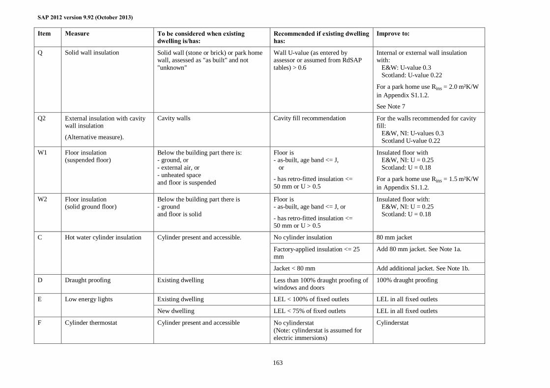
SAP 2012 version 9.92 (October 2013)
163
Item Measure To be considered when existing dwelling is/has:
Recommended if existing dwelling has:
Improve to:
Q Solid wall insulation Solid wall (stone or brick) or park home wall, assessed as "as built" and not "unknown"
Wall U-value (as entered by assessor or assumed from RdSAP tables) > 0.6
Internal or external wall insulation with: E&W: U-value 0.3 Scotland: U-value 0.22
For a park home use Rins = 2.0 m²K/W in Appendix S1.1.2.
See Note 7
Q2 External insulation with cavity wall insulation
(Alternative measure).
Cavity walls Cavity fill recommendation For the walls recommended for cavity fill: E&W, NI: U-values 0.3 Scotland U-value 0.22
W1 Floor insulation (suspended floor)
Below the building part there is: - ground, or - external air, or - unheated space and floor is suspended
Floor is - as-built, age band <= J, or
- has retro-fitted insulation <= 50 mm or U > 0.5
Insulated floor with E&W, NI: U = 0.25 Scotland: U = 0.18
For a park home use Rins = 1.5 m²K/W in Appendix S1.1.2.
W2 Floor insulation (solid ground floor)
Below the building part there is - ground and floor is solid
Floor is - as-built, age band <= J, or
- has retro-fitted insulation <= 50 mm or U > 0.5
Insulated floor with: E&W, NI: U = 0.25 Scotland: U = 0.18
No cylinder insulation 80 mm jacket
Factory-applied insulation <= 25 mm
Add 80 mm jacket. See Note 1a.
C Hot water cylinder insulation Cylinder present and accessible.
Jacket < 80 mm Add additional jacket. See Note 1b.
D Draught proofing Existing dwelling Less than 100% draught proofing of windows and doors
100% draught proofing
Existing dwelling LEL < 100% of fixed outlets LEL in all fixed outlets E Low energy lights
New dwelling LEL < 75% of fixed outlets LEL in all fixed outlets
F Cylinder thermostat Cylinder present and accessible No cylinderstat (Note: cylinderstat is assumed for electric immersions)
Cylinderstat
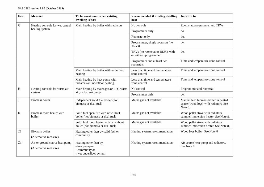
SAP 2012 version 9.92 (October 2013)
164
Item Measure To be considered when existing dwelling is/has:
Recommended if existing dwelling has:
Improve to:
No controls Roomstat, programmer and TRVs
Programmer only do.
Roomstat only do.
Programmer, single roomstat (no TRVs)
do.
TRVs (no roomstat or BEM), with or without programmer
do.
Main heating by boiler with radiators
Programmer and at least two roomstats
Time and temperature zone control
Main heating by boiler with underfloor heating
Less than time and temperature zone control
Time and temperature zone control
G Heating controls for wet central heating system
Main heating by heat pump with radiators or underfloor heating
Less than time and temperature zone control
Time and temperature zone control
No control Programmer and roomstat H Heating controls for warm air system
Main heating by mains gas or LPG warm air, or by heat pump Programmer only do.
J Biomass boiler Independent solid fuel boiler (not biomass or dual fuel)
Mains gas not available Manual feed biomass boiler in heated space (wood logs) with radiators. See Note 8.
Solid fuel open fire with or without boiler (not biomass or dual fuel)
Mains gas not available Wood pellet stove with radiators, summer immersion heater. See Note 8.
K Biomass room heater with boiler
Solid fuel room heater with or without boiler (not biomass or dual fuel)
Mains gas not available Wood pellet stove with radiators, summer immersion heater. See Note 8.
J2 Biomass boiler
(Alternative measure).
Heating other than by solid fuel or community
Heating system recommendation Wood logs boiler. See Note 8
Z1 Air or ground source heat pump
(Alternative measure).
Heating other than by: - heat pump or - community or - wet underfloor system
Heating system recommendation Air source heat pump and radiators. See Note 9
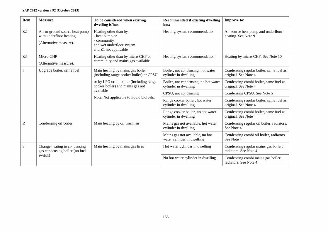
SAP 2012 version 9.92 (October 2013)
165
Item Measure To be considered when existing dwelling is/has:
Recommended if existing dwelling has:
Improve to:
Z2 Air or ground source heat pump with underfloor heating
(Alternative measure).
Heating other than by: - heat pump or - community and wet underfloor system and Z1 not applicable
Heating system recommendation Air source heat pump and underfloor heating. See Note 9
Z3 Micro-CHP
(Alternative measure).
Heating other than by micro-CHP or community and mains gas available
Heating system recommendation Heating by micro-CHP. See Note 10
Boiler, not condensing, hot water cylinder in dwelling
Condensing regular boiler, same fuel as original. See Note 4
Boiler, not condensing, no hot water cylinder in dwelling
Condensing combi boiler, same fuel as original. See Note 4
CPSU, not condensing Condensing CPSU. See Note 5
Range cooker boiler, hot water cylinder in dwelling
Condensing regular boiler, same fuel as original. See Note 4
I Upgrade boiler, same fuel Main heating by mains gas boiler (including range cooker boiler) or CPSU
or by LPG or oil boiler (including range cooker boiler) and mains gas not available
Note. Not applicable to liquid biofuels.
Range cooker boiler, no hot water cylinder in dwelling
Condensing combi boiler, same fuel as original. See Note 4
Mains gas not available, hot water cylinder in dwelling
Condensing regular oil boiler, radiators. See Note 4
R Condensing oil boiler Main heating by oil warm air
Mains gas not available, no hot water cylinder in dwelling
Condensing combi oil boiler, radiators. See Note 4
Hot water cylinder in dwelling Condensing regular mains gas boiler, radiators. See Note 4
S Change heating to condensing gas condensing boiler (no fuel switch)
Main heating by mains gas fires
No hot water cylinder in dwelling Condensing combi mains gas boiler, radiators. See Note 4
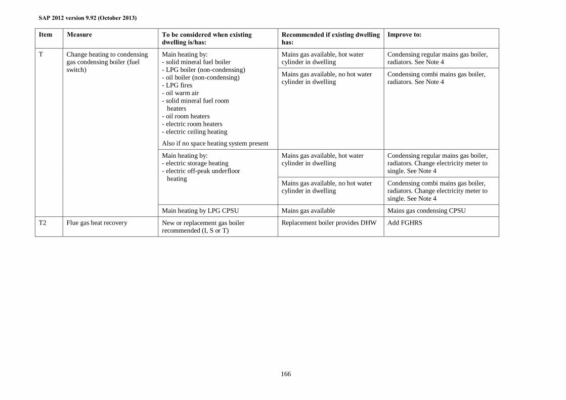
SAP 2012 version 9.92 (October 2013)
166
Item Measure To be considered when existing dwelling is/has:
Recommended if existing dwelling has:
Improve to:
Mains gas available, hot water cylinder in dwelling
Condensing regular mains gas boiler, radiators. See Note 4
Main heating by: - solid mineral fuel boiler - LPG boiler (non-condensing) - oil boiler (non-condensing) - LPG fires - oil warm air - solid mineral fuel room heaters - oil room heaters - electric room heaters - electric ceiling heating
Also if no space heating system present
Mains gas available, no hot water cylinder in dwelling
Condensing combi mains gas boiler, radiators. See Note 4
Mains gas available, hot water cylinder in dwelling
Condensing regular mains gas boiler, radiators. Change electricity meter to single. See Note 4
Main heating by: - electric storage heating - electric off-peak underfloor heating
Mains gas available, no hot water cylinder in dwelling
Condensing combi mains gas boiler, radiators. Change electricity meter to single. See Note 4
T Change heating to condensing gas condensing boiler (fuel switch)
Main heating by LPG CPSU Mains gas available Mains gas condensing CPSU
T2 Flue gas heat recovery New or replacement gas boiler recommended (I, S or T)
Replacement boiler provides DHW Add FGHRS
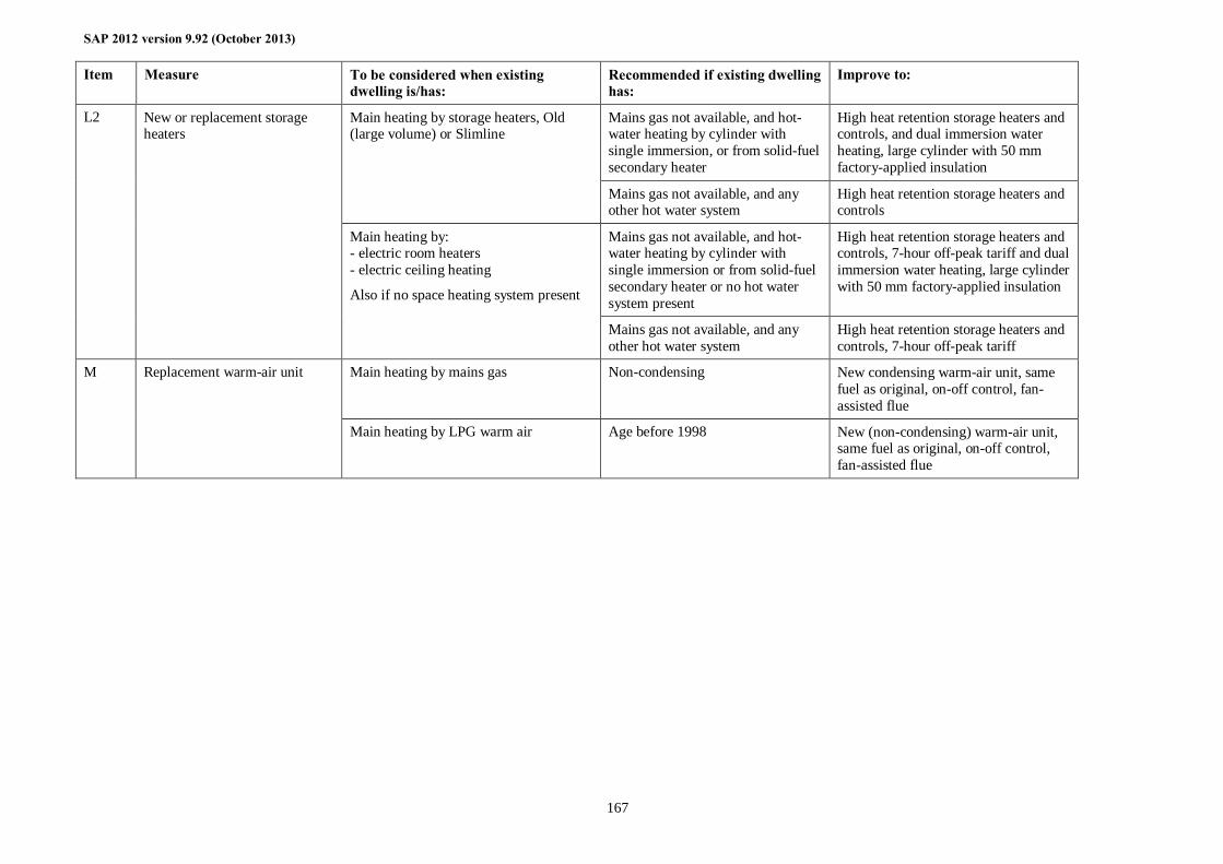
SAP 2012 version 9.92 (October 2013)
167
Item Measure To be considered when existing dwelling is/has:
Recommended if existing dwelling has:
Improve to:
Mains gas not available, and hot-water heating by cylinder with single immersion, or from solid-fuel secondary heater
High heat retention storage heaters and controls, and dual immersion water heating, large cylinder with 50 mm factory-applied insulation
Main heating by storage heaters, Old (large volume) or Slimline
Mains gas not available, and any other hot water system
High heat retention storage heaters and controls
Mains gas not available, and hot-water heating by cylinder with single immersion or from solid-fuel secondary heater or no hot water system present
High heat retention storage heaters and controls, 7-hour off-peak tariff and dual immersion water heating, large cylinder with 50 mm factory-applied insulation
L2 New or replacement storage heaters
Main heating by: - electric room heaters - electric ceiling heating
Also if no space heating system present
Mains gas not available, and any other hot water system
High heat retention storage heaters and controls, 7-hour off-peak tariff
Main heating by mains gas Non-condensing New condensing warm-air unit, same fuel as original, on-off control, fan-assisted flue
M Replacement warm-air unit
Main heating by LPG warm air Age before 1998 New (non-condensing) warm-air unit, same fuel as original, on-off control, fan-assisted flue
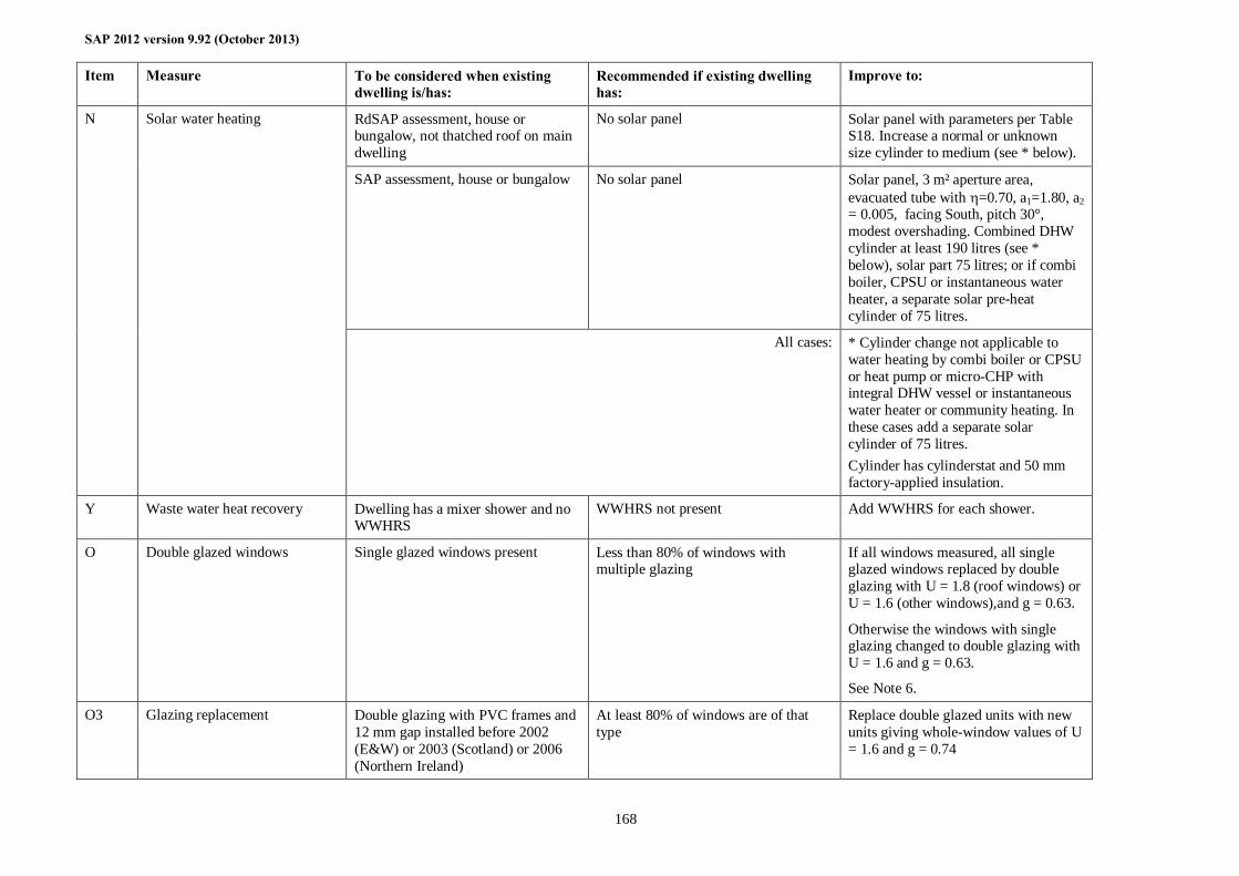
SAP 2012 version 9.92 (October 2013)
168
Item Measure To be considered when existing dwelling is/has:
Recommended if existing dwelling has:
Improve to:
RdSAP assessment, house or bungalow, not thatched roof on main dwelling
No solar panel Solar panel with parameters per Table S18. Increase a normal or unknown size cylinder to medium (see * below).
SAP assessment, house or bungalow No solar panel Solar panel, 3 m² aperture area, evacuated tube with η=0.70, a1=1.80, a2 = 0.005, facing South, pitch 30°, modest overshading. Combined DHW cylinder at least 190 litres (see * below), solar part 75 litres; or if combi boiler, CPSU or instantaneous water heater, a separate solar pre-heat cylinder of 75 litres.
N Solar water heating
All cases: * Cylinder change not applicable to water heating by combi boiler or CPSU or heat pump or micro-CHP with integral DHW vessel or instantaneous water heater or community heating. In these cases add a separate solar cylinder of 75 litres. Cylinder has cylinderstat and 50 mm factory-applied insulation.
Y Waste water heat recovery Dwelling has a mixer shower and no WWHRS
WWHRS not present Add WWHRS for each shower.
O Double glazed windows Single glazed windows present Less than 80% of windows with multiple glazing
If all windows measured, all single glazed windows replaced by double glazing with U = 1.8 (roof windows) or U = 1.6 (other windows),and g = 0.63.
Otherwise the windows with single glazing changed to double glazing with U = 1.6 and g = 0.63.
See Note 6.
O3 Glazing replacement Double glazing with PVC frames and 12 mm gap installed before 2002 (E&W) or 2003 (Scotland) or 2006 (Northern Ireland)
At least 80% of windows are of that type
Replace double glazed units with new units giving whole-window values of U = 1.6 and g = 0.74
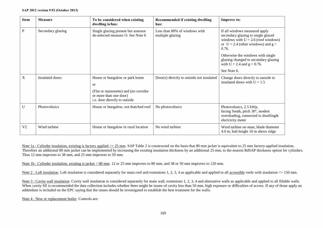
SAP 2012 version 9.92 (October 2013)
169
Item Measure To be considered when existing dwelling is/has:
Recommended if existing dwelling has:
Improve to:
P Secondary glazing Single glazing present but assessor de-selected measure O. See Note 6
Less than 80% of windows with multiple glazing
If all windows measured apply secondary glazing to single glazed windows with U = 2.6 (roof windows) or U = 2.4 (other windows) and g = 0.76.
Otherwise the windows with single glazing changed to secondary glazing with U = 2.4 and g = 0.76.
See Note 6.
X Insulated doors House or bungalow or park home
or
(Flat or maisonette) and (no corridor or more than one door) i.e. door directly to outside
Door(s) directly to outside not insulated Change doors directly to outside to insulated doors with U = 1.5
U Photovoltaics House or bungalow, not thatched roof No photovoltaics Photovoltaics, 2.5 kWp, facing South, pitch 30°, modest overshading, connected to dwelling’s electricity meter
V2 Wind turbine House or bungalow in rural location No wind turbine Wind turbine on mast, blade diameter 4.0 m, hub height 10 m above ridge
Note 1a : Cylinder insulation, existing is factory applied <= 25 mm. SAP Table 2 is constructed on the basis that 80 mm jacket is equivalent to 25 mm factory-applied insulation. Therefore an additional 80 mm jacket can be implemented by increasing the existing insulation thickness by an additional 25 mm, to the nearest RdSAP thickness option for cylinders. Thus 12 mm improves to 38 mm, and 25 mm improves to 50 mm. Note 1b : Cylinder insulation, existing is jacket < 80 mm. 12 or 25 mm improves to 80 mm, and 38 or 50 mm improves to 120 mm. Note 2 : Loft insulation. Loft insulation is considered separately for main roof and extensions 1, 2, 3, 4 as applicable and applied to all accessible roofs with insulation <= 150 mm. Note 3 : Cavity wall insulation. Cavity wall insulation is considered separately for main wall, extensions 1, 2, 3, 4 and alternative walls as applicable and applied to all fillable walls. When cavity fill is recommended the data collection includes whether there might be issues of cavity less than 50 mm, high exposure or difficulties of access. If any of those apply an addendum is included on the EPC saying that the issues should be investigated to establish the best treatment for the walls. Note 4 : New or replacement boiler. Controls are:
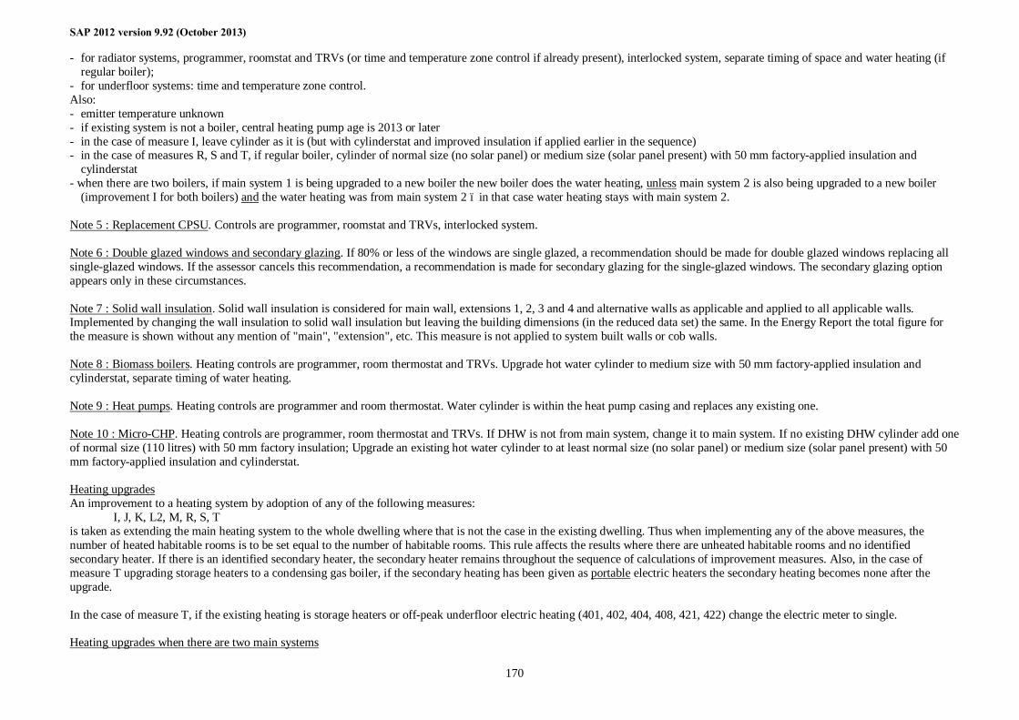
SAP 2012 version 9.92 (October 2013)
170
- for radiator systems, programmer, roomstat and TRVs (or time and temperature zone control if already present), interlocked system, separate timing of space and water heating (if regular boiler);
- for underfloor systems: time and temperature zone control. Also: - emitter temperature unknown - if existing system is not a boiler, central heating pump age is 2013 or later - in the case of measure I, leave cylinder as it is (but with cylinderstat and improved insulation if applied earlier in the sequence) - in the case of measures R, S and T, if regular boiler, cylinder of normal size (no solar panel) or medium size (solar panel present) with 50 mm factory-applied insulation and
cylinderstat - when there are two boilers, if main system 1 is being upgraded to a new boiler the new boiler does the water heating, unless main system 2 is also being upgraded to a new boiler
(improvement I for both boilers) and the water heating was from main system 2 – in that case water heating stays with main system 2. Note 5 : Replacement CPSU. Controls are programmer, roomstat and TRVs, interlocked system. Note 6 : Double glazed windows and secondary glazing. If 80% or less of the windows are single glazed, a recommendation should be made for double glazed windows replacing all single-glazed windows. If the assessor cancels this recommendation, a recommendation is made for secondary glazing for the single-glazed windows. The secondary glazing option appears only in these circumstances. Note 7 : Solid wall insulation. Solid wall insulation is considered for main wall, extensions 1, 2, 3 and 4 and alternative walls as applicable and applied to all applicable walls. Implemented by changing the wall insulation to solid wall insulation but leaving the building dimensions (in the reduced data set) the same. In the Energy Report the total figure for the measure is shown without any mention of "main", "extension", etc. This measure is not applied to system built walls or cob walls. Note 8 : Biomass boilers. Heating controls are programmer, room thermostat and TRVs. Upgrade hot water cylinder to medium size with 50 mm factory-applied insulation and cylinderstat, separate timing of water heating. Note 9 : Heat pumps. Heating controls are programmer and room thermostat. Water cylinder is within the heat pump casing and replaces any existing one. Note 10 : Micro-CHP. Heating controls are programmer, room thermostat and TRVs. If DHW is not from main system, change it to main system. If no existing DHW cylinder add one of normal size (110 litres) with 50 mm factory insulation; Upgrade an existing hot water cylinder to at least normal size (no solar panel) or medium size (solar panel present) with 50 mm factory-applied insulation and cylinderstat. Heating upgrades An improvement to a heating system by adoption of any of the following measures: I, J, K, L2, M, R, S, T is taken as extending the main heating system to the whole dwelling where that is not the case in the existing dwelling. Thus when implementing any of the above measures, the number of heated habitable rooms is to be set equal to the number of habitable rooms. This rule affects the results where there are unheated habitable rooms and no identified secondary heater. If there is an identified secondary heater, the secondary heater remains throughout the sequence of calculations of improvement measures. Also, in the case of measure T upgrading storage heaters to a condensing gas boiler, if the secondary heating has been given as portable electric heaters the secondary heating becomes none after the upgrade. In the case of measure T, if the existing heating is storage heaters or off-peak underfloor electric heating (401, 402, 404, 408, 421, 422) change the electric meter to single. Heating upgrades when there are two main systems
SAP 2012 version 9.92 (October 2013)
171
In the case of measure I (upgrade boiler, CPSU or range cooker, same fuel) where both systems each use the same fuel, apply the improvement to both boilers as applicable (i.e. boiler is non-condensing) as a single step. If the result attains the SAP increase criterion make the recommendation on the EPC using the improvement text applicable to main system 1 if both boilers are being upgraded. In the case of any other combination of main heating systems, apply the improvement to system 1 only. This includes measure I where that is relevant to main system 1 but not main system 2, as well as consideration of measures J, K, L2, M, R, S and T . Heating control upgrades when there are two main systems Apply the improvement to the controls on system 1 only, except apply improved controls to both boilers if both replaced.
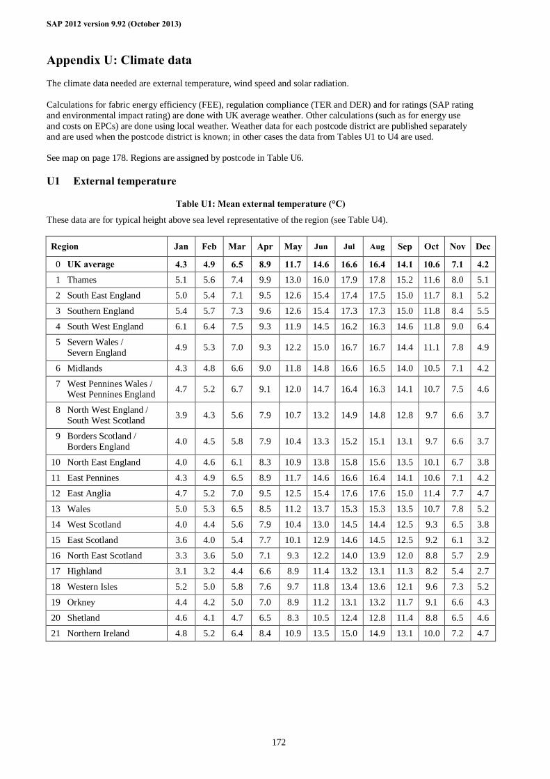
SAP 2012 version 9.92 (October 2013)
172
Appendix U: Climate data
The climate data needed are external temperature, wind speed and solar radiation. Calculations for fabric energy efficiency (FEE), regulation compliance (TER and DER) and for ratings (SAP rating and environmental impact rating) are done with UK average weather. Other calculations (such as for energy use and costs on EPCs) are done using local weather. Weather data for each postcode district are published separately and are used when the postcode district is known; in other cases the data from Tables U1 to U4 are used. See map on page 178. Regions are assigned by postcode in Table U6.
U1 External temperature
Table U1: Mean external temperature (°C)
These data are for typical height above sea level representative of the region (see Table U4).
Region Jan Feb Mar Apr May Jun Jul Aug Sep Oct Nov Dec
0 UK average 4.3 4.9 6.5 8.9 11.7 14.6 16.6 16.4 14.1 10.6 7.1 4.2 1 Thames 5.1 5.6 7.4 9.9 13.0 16.0 17.9 17.8 15.2 11.6 8.0 5.1
2 South East England 5.0 5.4 7.1 9.5 12.6 15.4 17.4 17.5 15.0 11.7 8.1 5.2
3 Southern England 5.4 5.7 7.3 9.6 12.6 15.4 17.3 17.3 15.0 11.8 8.4 5.5
4 South West England 6.1 6.4 7.5 9.3 11.9 14.5 16.2 16.3 14.6 11.8 9.0 6.4
5 Severn Wales / Severn England 4.9 5.3 7.0 9.3 12.2 15.0 16.7 16.7 14.4 11.1 7.8 4.9
6 Midlands 4.3 4.8 6.6 9.0 11.8 14.8 16.6 16.5 14.0 10.5 7.1 4.2
7 West Pennines Wales / West Pennines England 4.7 5.2 6.7 9.1 12.0 14.7 16.4 16.3 14.1 10.7 7.5 4.6
8 North West England / South West Scotland 3.9 4.3 5.6 7.9 10.7 13.2 14.9 14.8 12.8 9.7 6.6 3.7
9 Borders Scotland / Borders England 4.0 4.5 5.8 7.9 10.4 13.3 15.2 15.1 13.1 9.7 6.6 3.7
10 North East England 4.0 4.6 6.1 8.3 10.9 13.8 15.8 15.6 13.5 10.1 6.7 3.8
11 East Pennines 4.3 4.9 6.5 8.9 11.7 14.6 16.6 16.4 14.1 10.6 7.1 4.2
12 East Anglia 4.7 5.2 7.0 9.5 12.5 15.4 17.6 17.6 15.0 11.4 7.7 4.7
13 Wales 5.0 5.3 6.5 8.5 11.2 13.7 15.3 15.3 13.5 10.7 7.8 5.2
14 West Scotland 4.0 4.4 5.6 7.9 10.4 13.0 14.5 14.4 12.5 9.3 6.5 3.8
15 East Scotland 3.6 4.0 5.4 7.7 10.1 12.9 14.6 14.5 12.5 9.2 6.1 3.2
16 North East Scotland 3.3 3.6 5.0 7.1 9.3 12.2 14.0 13.9 12.0 8.8 5.7 2.9
17 Highland 3.1 3.2 4.4 6.6 8.9 11.4 13.2 13.1 11.3 8.2 5.4 2.7
18 Western Isles 5.2 5.0 5.8 7.6 9.7 11.8 13.4 13.6 12.1 9.6 7.3 5.2
19 Orkney 4.4 4.2 5.0 7.0 8.9 11.2 13.1 13.2 11.7 9.1 6.6 4.3
20 Shetland 4.6 4.1 4.7 6.5 8.3 10.5 12.4 12.8 11.4 8.8 6.5 4.6
21 Northern Ireland 4.8 5.2 6.4 8.4 10.9 13.5 15.0 14.9 13.1 10.0 7.2 4.7
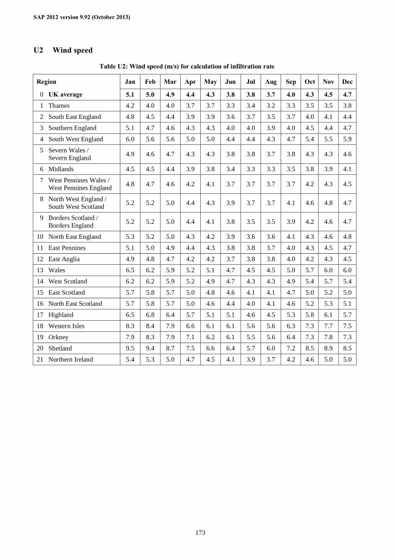
SAP 2012 version 9.92 (October 2013)
173
U2 Wind speed
Table U2: Wind speed (m/s) for calculation of infiltration rate
Region Jan Feb Mar Apr May Jun Jul Aug Sep Oct Nov Dec
0 UK average 5.1 5.0 4.9 4.4 4.3 3.8 3.8 3.7 4.0 4.3 4.5 4.7 1 Thames 4.2 4.0 4.0 3.7 3.7 3.3 3.4 3.2 3.3 3.5 3.5 3.8
2 South East England 4.8 4.5 4.4 3.9 3.9 3.6 3.7 3.5 3.7 4.0 4.1 4.4
3 Southern England 5.1 4.7 4.6 4.3 4.3 4.0 4.0 3.9 4.0 4.5 4.4 4.7
4 South West England 6.0 5.6 5.6 5.0 5.0 4.4 4.4 4.3 4.7 5.4 5.5 5.9
5 Severn Wales / Severn England 4.9 4.6 4.7 4.3 4.3 3.8 3.8 3.7 3.8 4.3 4.3 4.6
6 Midlands 4.5 4.5 4.4 3.9 3.8 3.4 3.3 3.3 3.5 3.8 3.9 4.1
7 West Pennines Wales / West Pennines England 4.8 4.7 4.6 4.2 4.1 3.7 3.7 3.7 3.7 4.2 4.3 4.5
8 North West England / South West Scotland 5.2 5.2 5.0 4.4 4.3 3.9 3.7 3.7 4.1 4.6 4.8 4.7
9 Borders Scotland / Borders England 5.2 5.2 5.0 4.4 4.1 3.8 3.5 3.5 3.9 4.2 4.6 4.7
10 North East England 5.3 5.2 5.0 4.3 4.2 3.9 3.6 3.6 4.1 4.3 4.6 4.8
11 East Pennines 5.1 5.0 4.9 4.4 4.3 3.8 3.8 3.7 4.0 4.3 4.5 4.7
12 East Anglia 4.9 4.8 4.7 4.2 4.2 3.7 3.8 3.8 4.0 4.2 4.3 4.5
13 Wales 6.5 6.2 5.9 5.2 5.1 4.7 4.5 4.5 5.0 5.7 6.0 6.0
14 West Scotland 6.2 6.2 5.9 5.2 4.9 4.7 4.3 4.3 4.9 5.4 5.7 5.4
15 East Scotland 5.7 5.8 5.7 5.0 4.8 4.6 4.1 4.1 4.7 5.0 5.2 5.0
16 North East Scotland 5.7 5.8 5.7 5.0 4.6 4.4 4.0 4.1 4.6 5.2 5.3 5.1
17 Highland 6.5 6.8 6.4 5.7 5.1 5.1 4.6 4.5 5.3 5.8 6.1 5.7
18 Western Isles 8.3 8.4 7.9 6.6 6.1 6.1 5.6 5.6 6.3 7.3 7.7 7.5
19 Orkney 7.9 8.3 7.9 7.1 6.2 6.1 5.5 5.6 6.4 7.3 7.8 7.3
20 Shetland 9.5 9.4 8.7 7.5 6.6 6.4 5.7 6.0 7.2 8.5 8.9 8.5
21 Northern Ireland 5.4 5.3 5.0 4.7 4.5 4.1 3.9 3.7 4.2 4.6 5.0 5.0
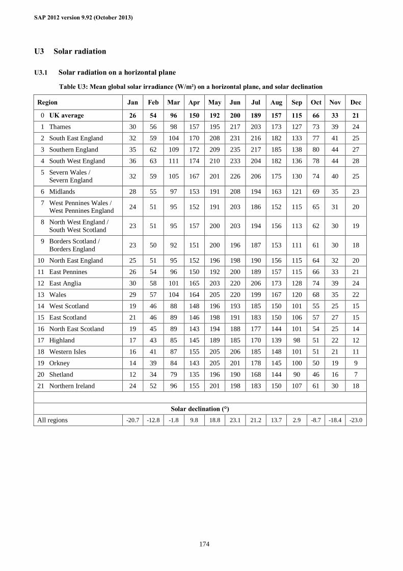
SAP 2012 version 9.92 (October 2013)
174
U3 Solar radiation
U3.1 Solar radiation on a horizontal plane
Table U3: Mean global solar irradiance (W/m²) on a horizontal plane, and solar declination
Region Jan Feb Mar Apr May Jun Jul Aug Sep Oct Nov Dec
0 UK average 26 54 96 150 192 200 189 157 115 66 33 21 1 Thames 30 56 98 157 195 217 203 173 127 73 39 24
2 South East England 32 59 104 170 208 231 216 182 133 77 41 25
3 Southern England 35 62 109 172 209 235 217 185 138 80 44 27
4 South West England 36 63 111 174 210 233 204 182 136 78 44 28
5 Severn Wales / Severn England 32 59 105 167 201 226 206 175 130 74 40 25
6 Midlands 28 55 97 153 191 208 194 163 121 69 35 23
7 West Pennines Wales / West Pennines England 24 51 95 152 191 203 186 152 115 65 31 20
8 North West England / South West Scotland 23 51 95 157 200 203 194 156 113 62 30 19
9 Borders Scotland / Borders England 23 50 92 151 200 196 187 153 111 61 30 18
10 North East England 25 51 95 152 196 198 190 156 115 64 32 20
11 East Pennines 26 54 96 150 192 200 189 157 115 66 33 21
12 East Anglia 30 58 101 165 203 220 206 173 128 74 39 24
13 Wales 29 57 104 164 205 220 199 167 120 68 35 22
14 West Scotland 19 46 88 148 196 193 185 150 101 55 25 15
15 East Scotland 21 46 89 146 198 191 183 150 106 57 27 15
16 North East Scotland 19 45 89 143 194 188 177 144 101 54 25 14
17 Highland 17 43 85 145 189 185 170 139 98 51 22 12
18 Western Isles 16 41 87 155 205 206 185 148 101 51 21 11
19 Orkney 14 39 84 143 205 201 178 145 100 50 19 9
20 Shetland 12 34 79 135 196 190 168 144 90 46 16 7
21 Northern Ireland 24 52 96 155 201 198 183 150 107 61 30 18
Solar declination (°) All regions -20.7 -12.8 -1.8 9.8 18.8 23.1 21.2 13.7 2.9 -8.7 -18.4 -23.0
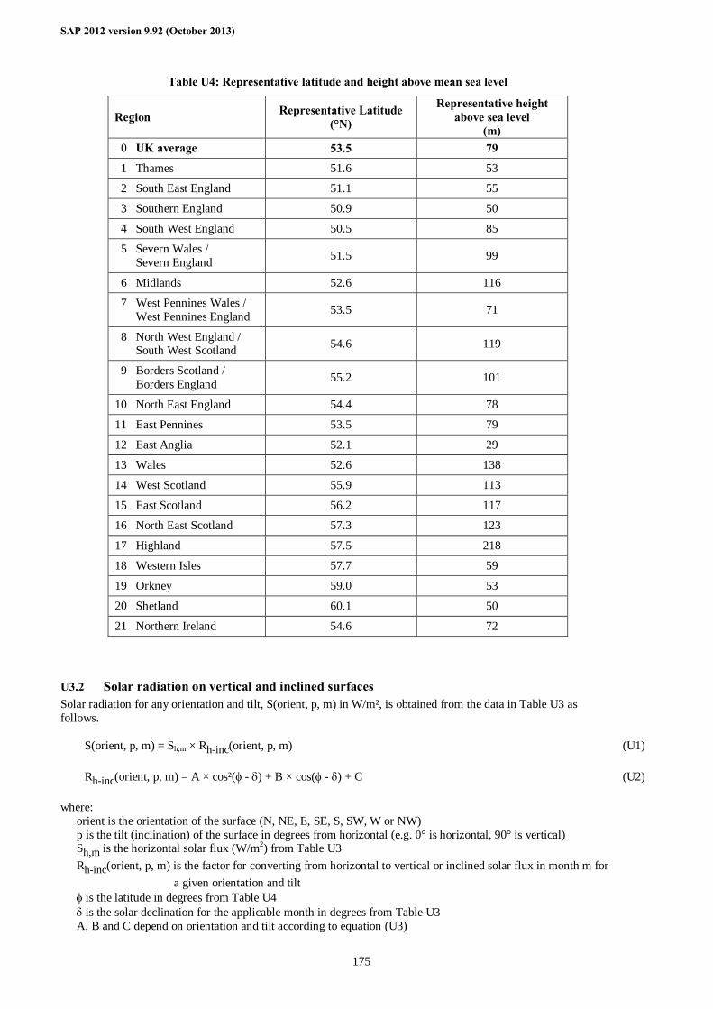
SAP 2012 version 9.92 (October 2013)
175
Table U4: Representative latitude and height above mean sea level
Region Representative Latitude (°N)
Representative height above sea level
(m) 0 UK average 53.5 79 1 Thames 51.6 53
2 South East England 51.1 55
3 Southern England 50.9 50
4 South West England 50.5 85
5 Severn Wales / Severn England 51.5 99
6 Midlands 52.6 116
7 West Pennines Wales / West Pennines England 53.5 71
8 North West England / South West Scotland 54.6 119
9 Borders Scotland / Borders England 55.2 101
10 North East England 54.4 78
11 East Pennines 53.5 79
12 East Anglia 52.1 29
13 Wales 52.6 138
14 West Scotland 55.9 113
15 East Scotland 56.2 117
16 North East Scotland 57.3 123
17 Highland 57.5 218
18 Western Isles 57.7 59
19 Orkney 59.0 53
20 Shetland 60.1 50
21 Northern Ireland 54.6 72
U3.2 Solar radiation on vertical and inclined surfaces Solar radiation for any orientation and tilt, S(orient, p, m) in W/m², is obtained from the data in Table U3 as follows.
S(orient, p, m) = Sh,m × Rh-inc(orient, p, m) (U1)
Rh-inc(orient, p, m) = A × cos²(φ - δ) + B × cos(φ - δ) + C (U2)
where: orient is the orientation of the surface (N, NE, E, SE, S, SW, W or NW) p is the tilt (inclination) of the surface in degrees from horizontal (e.g. 0° is horizontal, 90° is vertical) Sh,m is the horizontal solar flux (W/m2) from Table U3 Rh-inc(orient, p, m) is the factor for converting from horizontal to vertical or inclined solar flux in month m for
a given orientation and tilt φ is the latitude in degrees from Table U4 δ is the solar declination for the applicable month in degrees from Table U3 A, B and C depend on orientation and tilt according to equation (U3)
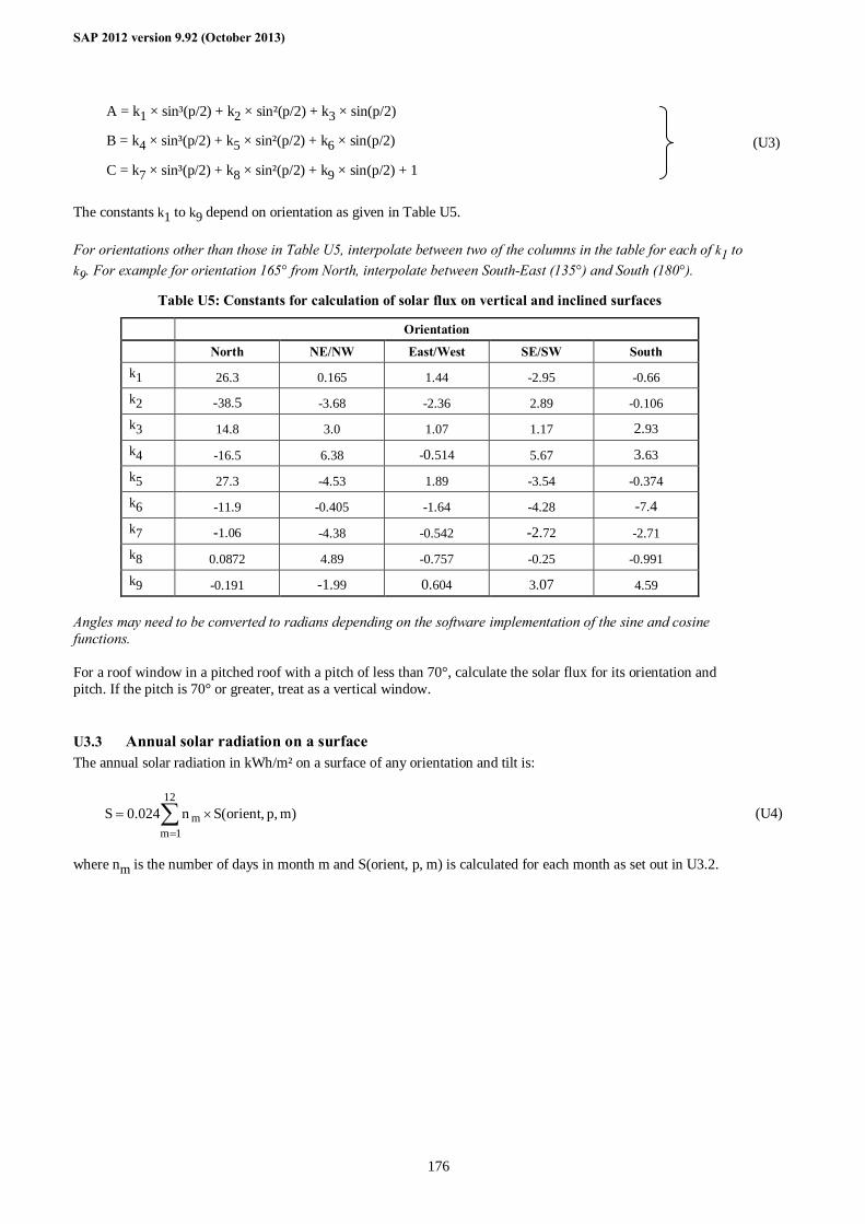
SAP 2012 version 9.92 (October 2013)
176
A = k1 × sin³(p/2) + k2 × sin²(p/2) + k3 × sin(p/2)
B = k4 × sin³(p/2) + k5 × sin²(p/2) + k6 × sin(p/2)
C = k7 × sin³(p/2) + k8 × sin²(p/2) + k9 × sin(p/2) + 1
(U3)
The constants k1 to k9 depend on orientation as given in Table U5. For orientations other than those in Table U5, interpolate between two of the columns in the table for each of k1 to k9. For example for orientation 165° from North, interpolate between South-East (135°) and South (180°).
Table U5: Constants for calculation of solar flux on vertical and inclined surfaces
Orientation
North NE/NW East/West SE/SW South k1 26.3 0.165 1.44 -2.95 -0.66 k2 -38.5 -3.68 -2.36 2.89 -0.106 k3 14.8 3.0 1.07 1.17 2.93
k4 -16.5 6.38 -0.514 5.67 3.63 k5 27.3 -4.53 1.89 -3.54 -0.374 k6 -11.9 -0.405 -1.64 -4.28 -7.4
k7 -1.06 -4.38 -0.542 -2.72 -2.71 k8 0.0872 4.89 -0.757 -0.25 -0.991 k9 -0.191 -1.99 0.604 3.07 4.59
Angles may need to be converted to radians depending on the software implementation of the sine and cosine functions. For a roof window in a pitched roof with a pitch of less than 70°, calculate the solar flux for its orientation and pitch. If the pitch is 70° or greater, treat as a vertical window.
U3.3 Annual solar radiation on a surface The annual solar radiation in kWh/m² on a surface of any orientation and tilt is:
∑=
×=12
1mm )m,p,orient(Sn024.0S (U4)
where nm is the number of days in month m and S(orient, p, m) is calculated for each month as set out in U3.2.
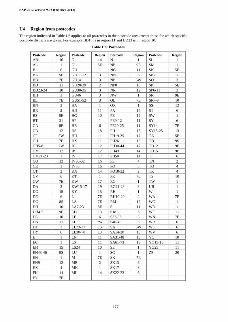
SAP 2012 version 9.92 (October 2013)
177
U4 Region from postcodes The region indicated in Table U6 applies to all postcodes in the postcode area except those for which specific postcode districts are given. For example BD16 is in region 11 and BD23 is in region 10.
Table U6: Postcodes
Postcode Region Postcode Region Postcode Region Postcode Region AB 16 G 14 N 1 SL 1 AL 1 GL 5E NE 9E SM 1 B 6 GU 1 NG 11 SN 5E BA 5E GU11-12 3 NN 6 SN7 1 BB 7E GU14 3 NP 5W SO 3 BD 11 GU28-29 2 NP8 13 SP 5E BD23-24 10 GU30-35 3 NR 12 SP6-11 3 BH 3 GU46 3 NW 1 SR 9E BL 7E GU51-52 3 OL 7E SR7-8 10 BN 2 HA 1 OX 1 SS 12 BR 2 HD 11 PA 14 ST 6 BS 5E HG 10 PE 12 SW 1 BT 21 HP 1 PE9-12 11 SY 6 CA 8E HR 6 PE20-25 11 SY14 7E CB 12 HS 18 PH 15 SY15-25 13 CF 5W HU 11 PH19-25 17 TA 5E CH 7E HX 11 PH26 16 TD 9S CH5-8 7W IG 12 PH30-44 17 TD12 9E CM 12 IP 12 PH49 14 TD15 9E CM21-23 1 IV 17 PH50 14 TF 6 CO 12 IV30-32 16 PL 4 TN 2 CR 1 IV36 16 PO 3 TQ 4 CT 2 KA 14 PO18-22 2 TR 4 CV 6 KT 1 PR 7E TS 10 CW 7E KW 17 RG 1 TW 1 DA 2 KW15-17 19 RG21-29 3 UB 1 DD 15 KY 15 RH 1 W 1 DE 6 L 7E RH10-20 2 WA 7E DG 8S LA 7E RM 12 WC 1 DH 10 LA7-23 8E S 11 WD 1 DH4-5 9E LD 13 S18 6 WF 11 DL 10 LE 6 S32-33 6 WN 7E DN 11 LL 7W S40-45 6 WR 6 DT 3 LL23-27 13 SA 5W WS 6 DY 6 LL30-78 13 SA14-20 13 WV 6 E 1 LN 11 SA31-48 13 YO 10 EC 1 LS 11 SA61-73 13 YO15-16 11 EH 15 LS24 10 SE 1 YO25 11 EH43-46 9S LU 1 SG 1 ZE 20 EN 1 M 7E SK 7E EN9 12 ME 2 SK13 6 EX 4 MK 1 SK17 6 FK 14 ML 14 SK22-23 6 FY 7E
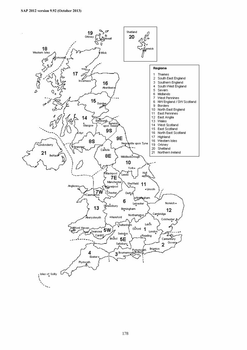
SAP 2012 version 9.92 (October 2013)
178
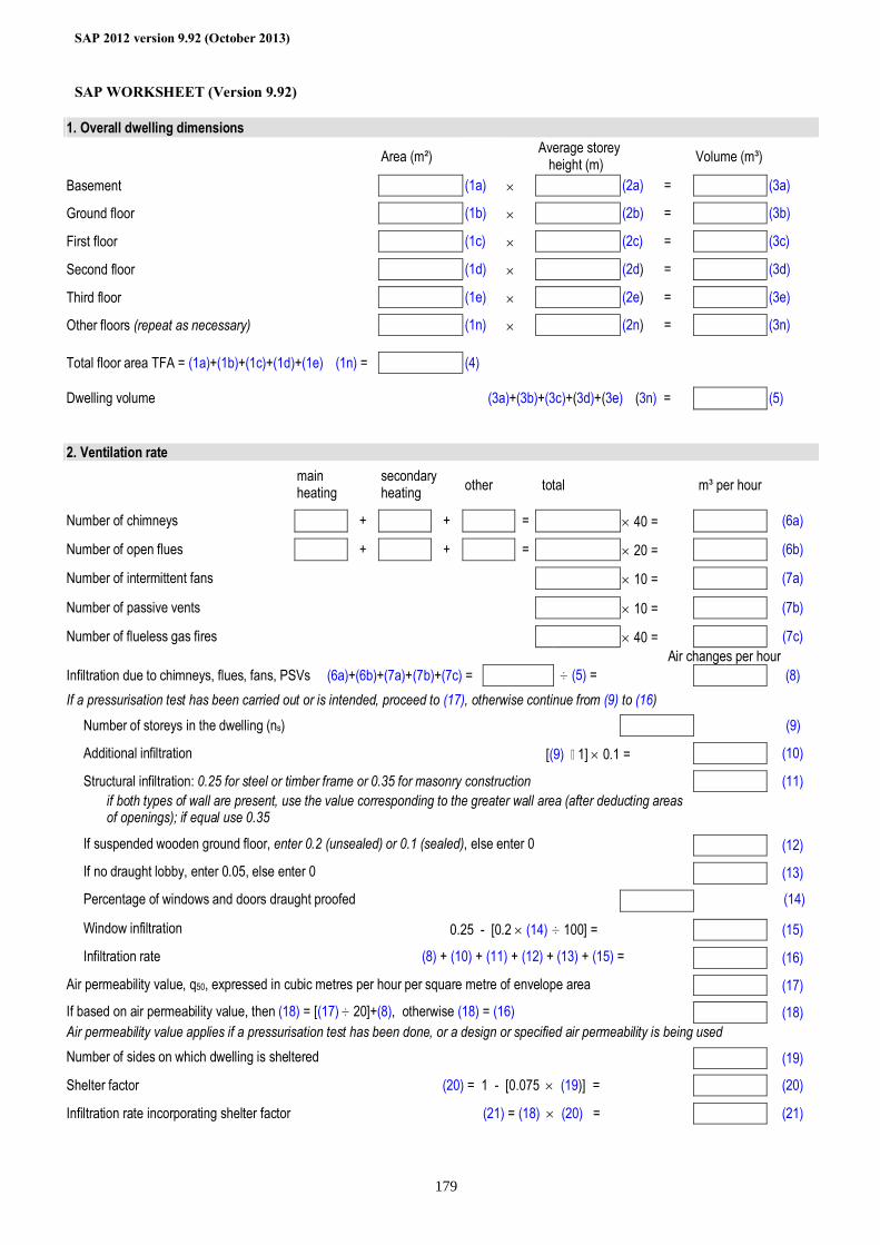
SAP 2012 version 9.92 (October 2013)
179
SAP WORKSHEET (Version 9.92)
1. Overall dwelling dimensions Area (m²) Average storey
height (m) Volume (m³)
Basement (1a) × (2a) = (3a) Ground floor (1b) × (2b) = (3b) First floor (1c) × (2c) = (3c) Second floor (1d) × (2d) = (3d) Third floor (1e) × (2e) = (3e) Other floors (repeat as necessary) (1n) × (2n) = (3n) Total floor area TFA = (1a)+(1b)+(1c)+(1d)+(1e)…(1n) = (4)
Dwelling volume (3a)+(3b)+(3c)+(3d)+(3e)…(3n) = (5)
2. Ventilation rate
main heating
secondary heating other total m³ per hour
Number of chimneys + + = × 40 = (6a) Number of open flues + + = × 20 = (6b) Number of intermittent fans × 10 = (7a)
Number of passive vents × 10 = (7b) Number of flueless gas fires × 40 = (7c)
Air changes per hour Infiltration due to chimneys, flues, fans, PSVs (6a)+(6b)+(7a)+(7b)+(7c) = ÷ (5) = (8)
If a pressurisation test has been carried out or is intended, proceed to (17), otherwise continue from (9) to (16)
Number of storeys in the dwelling (ns) (9) Additional infiltration [(9) – 1] × 0.1 = (10) Structural infiltration: 0.25 for steel or timber frame or 0.35 for masonry construction (11)
if both types of wall are present, use the value corresponding to the greater wall area (after deducting areas of openings); if equal use 0.35
If suspended wooden ground floor, enter 0.2 (unsealed) or 0.1 (sealed), else enter 0 (12) If no draught lobby, enter 0.05, else enter 0 (13) Percentage of windows and doors draught proofed (14) Window infiltration 0.25 - [0.2 × (14) ÷ 100] = (15) Infiltration rate (8) + (10) + (11) + (12) + (13) + (15) = (16)
Air permeability value, q50, expressed in cubic metres per hour per square metre of envelope area (17) If based on air permeability value, then (18) = [(17) ÷ 20]+(8), otherwise (18) = (16) (18) Air permeability value applies if a pressurisation test has been done, or a design or specified air permeability is being used Number of sides on which dwelling is sheltered (19) Shelter factor (20) = 1 - [0.075 × (19)] = (20) Infiltration rate incorporating shelter factor (21) = (18) × (20) = (21)
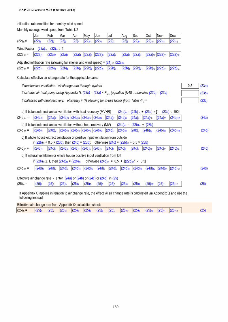
SAP 2012 version 9.92 (October 2013)
180
Infiltration rate modified for monthly wind speed: Monthly average wind speed from Table U2
Jan Feb Mar Apr May Jun Jul Aug Sep Oct Nov Dec (22)m = (22)1 (22)2 (22)3 (22)4 (22)5 (22)6 (22)7 (22)8 (22)9 (22)10 (22)11 (22)12 Wind Factor (22a)m = (22)m ÷ 4 (22a)m = (22a)1 (22a)2 (22a)3 (22a)4 (22a)5 (22a)6 (22a)7 (22a)8 (22a)9 (22a)10 (22a)11 (22a)12 Adjusted infiltration rate (allowing for shelter and wind speed) = (21) × (22a)m (22b)m = (22b)1 (22b)2 (22b)3 (22b)4 (22b)5 (22b)6 (22b)7 (22b)8 (22b)9 (22b)10 (22b)11 (22b)12
Calculate effective air change rate for the applicable case: If mechanical ventilation: air change rate through system 0.5 (23a) If exhaust air heat pump using Appendix N, (23b) = (23a) × Fmv (equation (N4)) , otherwise (23b) = (23a) (23b) If balanced with heat recovery: efficiency in % allowing for in-use factor (from Table 4h) = (23c) a) If balanced mechanical ventilation with heat recovery (MVHR) (24a)m = (22b)m + (23b) × [1 – (23c) ÷ 100] (24a)m = (24a)1 (24a)2 (24a)3 (24a)4 (24a)5 (24a)6 (24a)7 (24a)8 (24a)9 (24a)10 (24a)11 (24a)12 (24a) b) If balanced mechanical ventilation without heat recovery (MV) (24b)m = (22b)m + (23b) (24b)m = (24b)1 (24b)2 (24b)3 (24b)4 (24b)5 (24b)6 (24b)7 (24b)8 (24b)9 (24b)10 (24b)11 (24b)12 (24b) c) If whole house extract ventilation or positive input ventilation from outside if (22b)m < 0.5 × (23b), then (24c) = (23b); otherwise (24c) = (22b) m + 0.5 × (23b) (24c)m = (24c)1 (24c)2 (24c)3 (24c)4 (24c)5 (24c)6 (24c)7 (24c)8 (24c)9 (24c)10 (24c)11 (24c)12 (24c) d) If natural ventilation or whole house positive input ventilation from loft if (22b)m ≥ 1, then (24d)m = (22b)m otherwise (24d)m = 0.5 + [(22b)m² × 0.5] (24d)m = (24d)1 (24d)2 (24d)3 (24d)4 (24d)5 (24d)6 (24d)7 (24d)8 (24d)9 (24d)10 (24d)11 (24d)12 (24d)
Effective air change rate - enter (24a) or (24b) or (24c) or (24d) in (25) (25)m = (25)1 (25)2 (25)3 (25)4 (25)5 (25)6 (25)7 (25)8 (25)9 (25)10 (25)11 (25)12 (25)
If Appendix Q applies in relation to air change rate, the effective air change rate is calculated via Appendix Q and use the following instead:
Effective air change rate from Appendix Q calculation sheet: (25)m = (25)1 (25)2 (25)3 (25)4 (25)5 (25)6 (25)7 (25)8 (25)9 (25)10 (25)11 (25)12 (25)
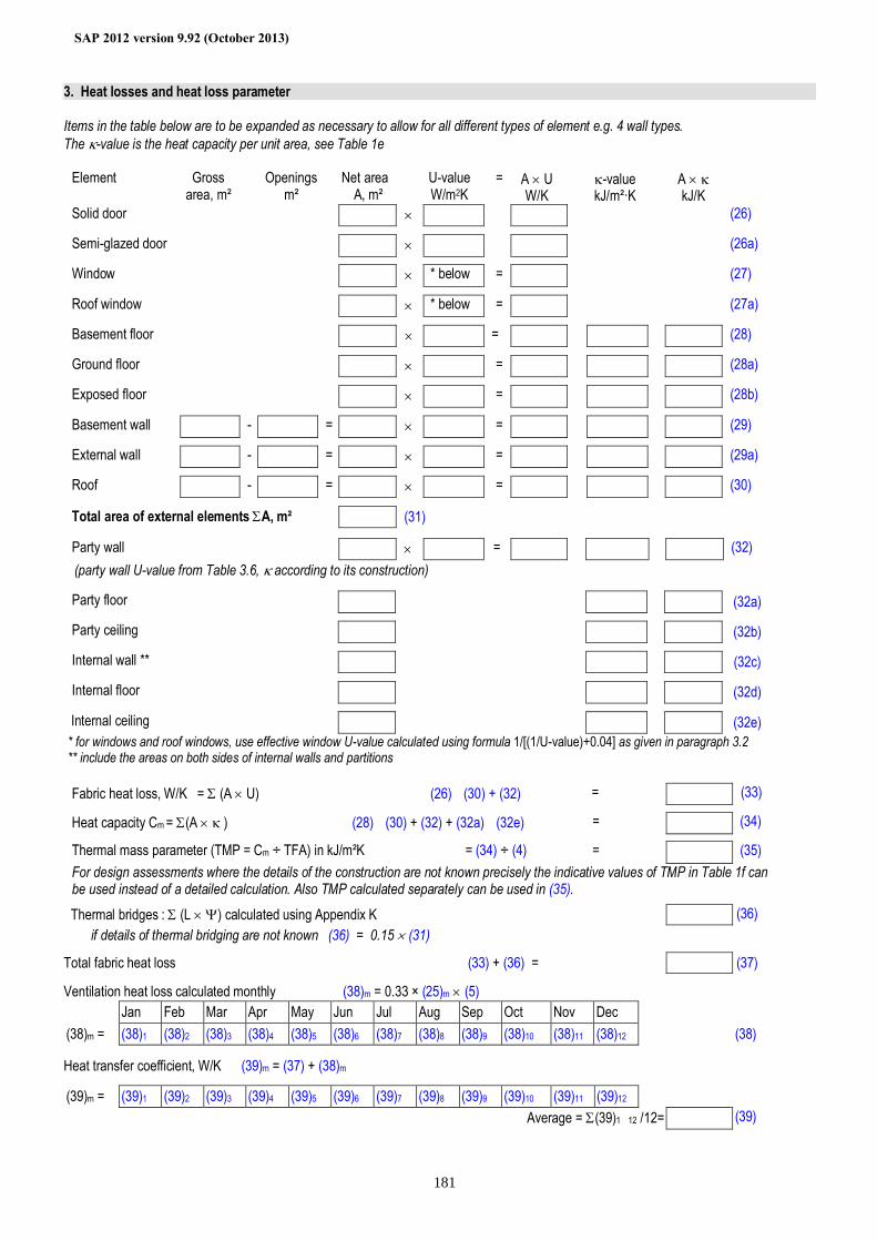
SAP 2012 version 9.92 (October 2013)
181
3. Heat losses and heat loss parameter
Items in the table below are to be expanded as necessary to allow for all different types of element e.g. 4 wall types. The κ-value is the heat capacity per unit area, see Table 1e
Element Gross
area, m² Openings
m² Net area
A, m² U-value
W/m2K = A × U
W/K κ-value
kJ/m²·K A × κ
kJ/K
Solid door × (26) Semi-glazed door × (26a) Window × * below = (27) Roof window × * below = (27a) Basement floor × = (28) Ground floor × = (28a) Exposed floor × = (28b) Basement wall - = × = (29) External wall - = × = (29a) Roof - = × = (30) Total area of external elements ΣA, m² (31) Party wall × = (32) (party wall U-value from Table 3.6, κ according to its construction)
Party floor (32a) Party ceiling (32b) Internal wall ** (32c) Internal floor (32d) Internal ceiling (32e)
* for windows and roof windows, use effective window U-value calculated using formula 1/[(1/U-value)+0.04] as given in paragraph 3.2 ** include the areas on both sides of internal walls and partitions Fabric heat loss, W/K = Σ (A × U) (26)…(30) + (32) = (33)
Heat capacity Cm = Σ(A × κ ) (28)…(30) + (32) + (32a)…(32e) = (34)
Thermal mass parameter (TMP = Cm ÷ TFA) in kJ/m²K = (34) ÷ (4) = (35) For design assessments where the details of the construction are not known precisely the indicative values of TMP in Table 1f can be used instead of a detailed calculation. Also TMP calculated separately can be used in (35).
Thermal bridges : Σ (L × Ψ) calculated using Appendix K (36) if details of thermal bridging are not known (36) = 0.15 × (31)
Total fabric heat loss (33) + (36) = (37) Ventilation heat loss calculated monthly (38)m = 0.33 × (25)m × (5) Jan Feb Mar Apr May Jun Jul Aug Sep Oct Nov Dec (38)m = (38)1 (38)2 (38)3 (38)4 (38)5 (38)6 (38)7 (38)8 (38)9 (38)10 (38)11 (38)12 (38)
Heat transfer coefficient, W/K (39)m = (37) + (38)m
(39)m = (39)1 (39)2 (39)3 (39)4 (39)5 (39)6 (39)7 (39)8 (39)9 (39)10 (39)11 (39)12 Average = Σ(39)1…12 /12= (39)
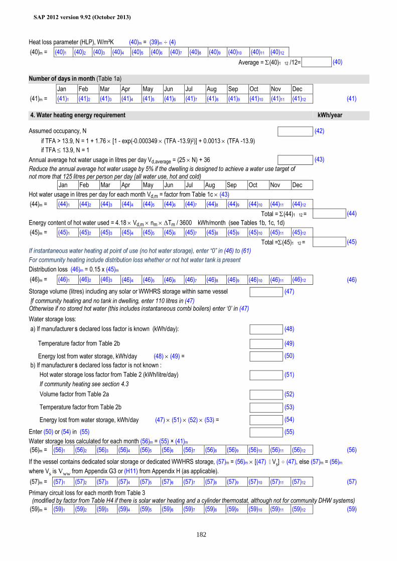
SAP 2012 version 9.92 (October 2013)
182
Heat loss parameter (HLP), W/m²K (40)m = (39)m ÷ (4) (40)m = (40)1 (40)2 (40)3 (40)4 (40)5 (40)6 (40)7 (40)8 (40)9 (40)10 (40)11 (40)12 Average = Σ(40)1…12 /12= (40)
Number of days in month (Table 1a) Jan Feb Mar Apr May Jun Jul Aug Sep Oct Nov Dec (41)m = (41)1 (41)2 (41)3 (41)4 (41)5 (41)6 (41)7 (41)8 (41)9 (41)10 (41)11 (41)12 (41)
4. Water heating energy requirement kWh/year
Assumed occupancy, N (42) if TFA > 13.9, N = 1 + 1.76 × [1 - exp(-0.000349 × (TFA -13.9)2)] + 0.0013 × (TFA -13.9) if TFA ≤ 13.9, N = 1 Annual average hot water usage in litres per day Vd,average = (25 × N) + 36 (43) Reduce the annual average hot water usage by 5% if the dwelling is designed to achieve a water use target of not more that 125 litres per person per day (all water use, hot and cold) Jan Feb Mar Apr May Jun Jul Aug Sep Oct Nov Dec Hot water usage in litres per day for each month Vd,m = factor from Table 1c × (43) (44)m = (44)1 (44)2 (44)3 (44)4 (44)5 (44)6 (44)7 (44)8 (44)9 (44)10 (44)11 (44)12 Total = Σ(44)1…12 = (44) Energy content of hot water used = 4.18 × Vd,m × nm × ∆Tm / 3600 kWh/month (see Tables 1b, 1c, 1d) (45)m = (45)1 (45)2 (45)3 (45)4 (45)5 (45)6 (45)7 (45)8 (45)9 (45)10 (45)11 (45)12 Total =Σ(45)1…12 = (45) If instantaneous water heating at point of use (no hot water storage), enter “0” in (46) to (61) For community heating include distribution loss whether or not hot water tank is present Distribution loss (46)m = 0.15 x (45)m (46)m = (46)1 (46)2 (46)3 (46)4 (46)5 (46)6 (46)7 (46)8 (46)9 (46)10 (46)11 (46)12 (46) Storage volume (litres) including any solar or WWHRS storage within same vessel (47) If community heating and no tank in dwelling, enter 110 litres in (47) Otherwise if no stored hot water (this includes instantaneous combi boilers) enter ‘0’ in (47) Water storage loss: a) If manufacturer’s declared loss factor is known (kWh/day): (48) Temperature factor from Table 2b (49) Energy lost from water storage, kWh/day (48) × (49) = (50) b) If manufacturer’s declared loss factor is not known : Hot water storage loss factor from Table 2 (kWh/litre/day) (51) If community heating see section 4.3 Volume factor from Table 2a (52)
Temperature factor from Table 2b (53) Energy lost from water storage, kWh/day (47) × (51) × (52) × (53) = (54) Enter (50) or (54) in (55) (55) Water storage loss calculated for each month (56)m = (55) × (41)m (56)m = (56)1 (56)2 (56)3 (56)4 (56)5 (56)6 (56)7 (56)8 (56)9 (56)10 (56)11 (56)12 (56) If the vessel contains dedicated solar storage or dedicated WWHRS storage, (57)m = (56)m × [(47) – Vs] ÷ (47), else (57)m = (56)m where Vs is Vww from Appendix G3 or (H11) from Appendix H (as applicable). (57)m = (57)1 (57)2 (57)3 (57)4 (57)5 (57)6 (57)7 (57)8 (57)9 (57)10 (57)11 (57)12 (57) Primary circuit loss for each month from Table 3 (modified by factor from Table H4 if there is solar water heating and a cylinder thermostat, although not for community DHW systems) (59)m = (59)1 (59)2 (59)3 (59)4 (59)5 (59)6 (59)7 (59)8 (59)9 (59)10 (59)11 (59)12 (59)
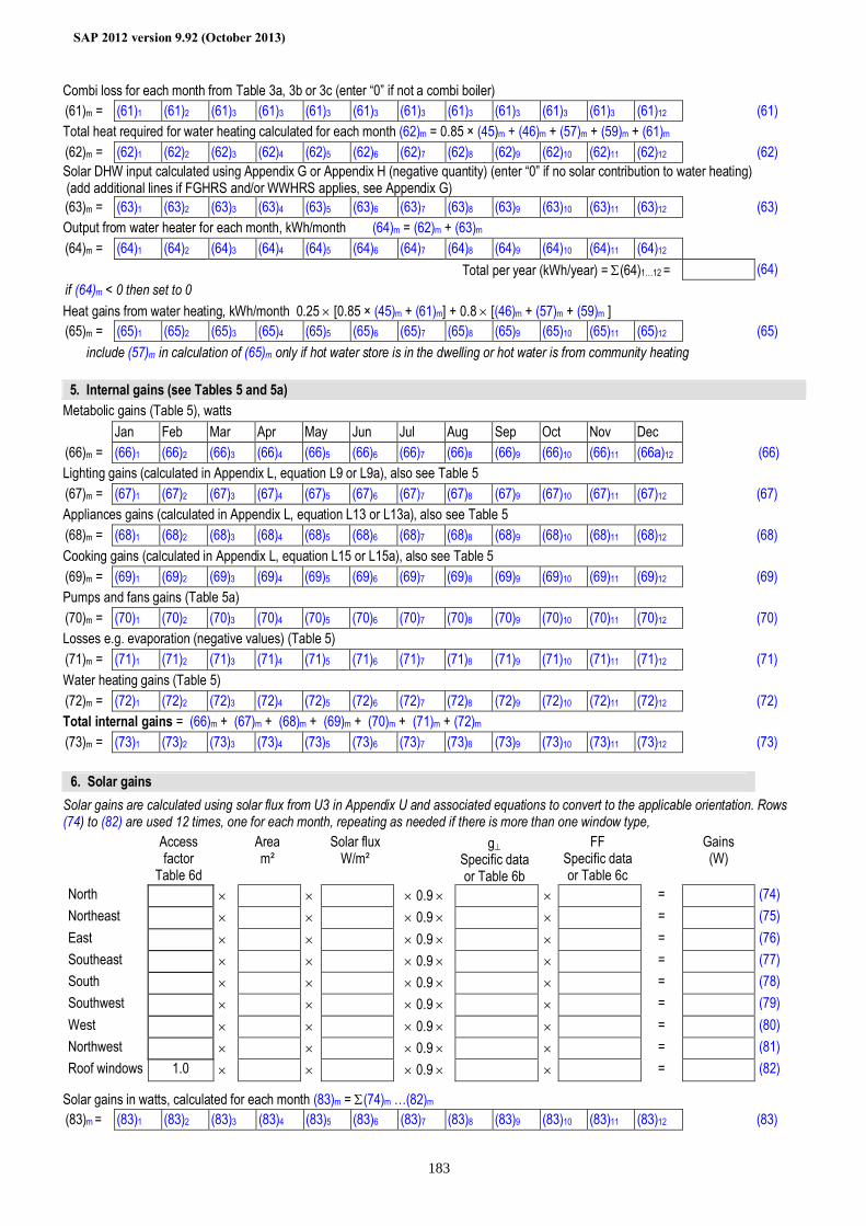
SAP 2012 version 9.92 (October 2013)
183
Combi loss for each month from Table 3a, 3b or 3c (enter “0” if not a combi boiler) (61)m = (61)1 (61)2 (61)3 (61)3 (61)3 (61)3 (61)3 (61)3 (61)3 (61)3 (61)3 (61)12 (61) Total heat required for water heating calculated for each month (62)m = 0.85 × (45)m + (46)m + (57)m + (59)m + (61)m (62)m = (62)1 (62)2 (62)3 (62)4 (62)5 (62)6 (62)7 (62)8 (62)9 (62)10 (62)11 (62)12 (62) Solar DHW input calculated using Appendix G or Appendix H (negative quantity) (enter “0” if no solar contribution to water heating) (add additional lines if FGHRS and/or WWHRS applies, see Appendix G) (63)m = (63)1 (63)2 (63)3 (63)4 (63)5 (63)6 (63)7 (63)8 (63)9 (63)10 (63)11 (63)12 (63) Output from water heater for each month, kWh/month (64)m = (62)m + (63)m (64)m = (64)1 (64)2 (64)3 (64)4 (64)5 (64)6 (64)7 (64)8 (64)9 (64)10 (64)11 (64)12 Total per year (kWh/year) = Σ(64)1…12 = (64) if (64)m < 0 then set to 0 Heat gains from water heating, kWh/month 0.25 × [0.85 × (45)m + (61)m] + 0.8 × [(46)m + (57)m + (59)m ] (65)m = (65)1 (65)2 (65)3 (65)4 (65)5 (65)6 (65)7 (65)8 (65)9 (65)10 (65)11 (65)12 (65) include (57)m in calculation of (65)m only if hot water store is in the dwelling or hot water is from community heating
5. Internal gains (see Tables 5 and 5a) Metabolic gains (Table 5), watts Jan Feb Mar Apr May Jun Jul Aug Sep Oct Nov Dec (66)m = (66)1 (66)2 (66)3 (66)4 (66)5 (66)6 (66)7 (66)8 (66)9 (66)10 (66)11 (66a)12 (66) Lighting gains (calculated in Appendix L, equation L9 or L9a), also see Table 5 (67)m = (67)1 (67)2 (67)3 (67)4 (67)5 (67)6 (67)7 (67)8 (67)9 (67)10 (67)11 (67)12 (67) Appliances gains (calculated in Appendix L, equation L13 or L13a), also see Table 5 (68)m = (68)1 (68)2 (68)3 (68)4 (68)5 (68)6 (68)7 (68)8 (68)9 (68)10 (68)11 (68)12 (68) Cooking gains (calculated in Appendix L, equation L15 or L15a), also see Table 5 (69)m = (69)1 (69)2 (69)3 (69)4 (69)5 (69)6 (69)7 (69)8 (69)9 (69)10 (69)11 (69)12 (69) Pumps and fans gains (Table 5a) (70)m = (70)1 (70)2 (70)3 (70)4 (70)5 (70)6 (70)7 (70)8 (70)9 (70)10 (70)11 (70)12 (70) Losses e.g. evaporation (negative values) (Table 5) (71)m = (71)1 (71)2 (71)3 (71)4 (71)5 (71)6 (71)7 (71)8 (71)9 (71)10 (71)11 (71)12 (71) Water heating gains (Table 5) (72)m = (72)1 (72)2 (72)3 (72)4 (72)5 (72)6 (72)7 (72)8 (72)9 (72)10 (72)11 (72)12 (72) Total internal gains = (66)m + (67)m + (68)m + (69)m + (70)m + (71)m + (72)m (73)m = (73)1 (73)2 (73)3 (73)4 (73)5 (73)6 (73)7 (73)8 (73)9 (73)10 (73)11 (73)12 (73)
6. Solar gains Solar gains are calculated using solar flux from U3 in Appendix U and associated equations to convert to the applicable orientation. Rows (74) to (82) are used 12 times, one for each month, repeating as needed if there is more than one window type, Access
factor Table 6d
Area m²
Solar flux W/m²
g⊥ Specific data or Table 6b
FF Specific data or Table 6c
Gains (W)
North × × × 0.9 × × = (74) Northeast × × × 0.9 × × = (75) East × × × 0.9 × × = (76) Southeast × × × 0.9 × × = (77) South × × × 0.9 × × = (78) Southwest × × × 0.9 × × = (79) West × × × 0.9 × × = (80) Northwest × × × 0.9 × × = (81) Roof windows 1.0 × × × 0.9 × × = (82)
Solar gains in watts, calculated for each month (83)m = Σ(74)m …(82)m (83)m = (83)1 (83)2 (83)3 (83)4 (83)5 (83)6 (83)7 (83)8 (83)9 (83)10 (83)11 (83)12 (83)
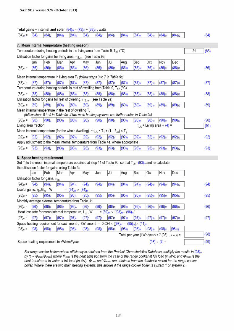
SAP 2012 version 9.92 (October 2013)
184
Total gains – internal and solar (84)m = (73)m + (83)m , watts (84)m = (84)1 (84)2 (84)3 (84)4 (84)5 (84)6 (84)7 (84)8 (84)9 (84)10 (84)11 (84)12 (84)
7. Mean internal temperature (heating season) Temperature during heating periods in the living area from Table 9, Th1 (°C) 21 (85) Utilisation factor for gains for living area, η1,m (see Table 9a) Jan Feb Mar Apr May Jun Jul Aug Sep Oct Nov Dec (86)m = (86)1 (86)2 (86)3 (86)4 (86)5 (86)6 (86)7 (86)8 (86)9 (86)10 (86)11 (86)12 (86) Mean internal temperature in living area T1 (follow steps 3 to 7 in Table 9c) (87)m = (87)1 (87)2 (87)3 (87)4 (87)5 (87)6 (87)7 (87)8 (87)9 (87)10 (87)11 (87)12 (87) Temperature during heating periods in rest of dwelling from Table 9, Th2 (°C) (88)m = (88)1 (88)2 (88)3 (88)4 (88)5 (88)6 (88)7 (88)8 (88)9 (88)10 (88)11 (88)12 (88) Utilisation factor for gains for rest of dwelling, η2,m (see Table 9a) (89)m = (89)1 (89)2 (89)3 (89)4 (89)5 (89)6 (89)7 (89)8 (89)9 (89)10 (89)11 (89)12 (89) Mean internal temperature in the rest of dwelling T2
(follow steps 8 to 9 in Table 9c, if two main heating systems see further notes in Table 9c) (90)m = (90)1 (90)2 (90)3 (90)4 (90)5 (90)6 (90)7 (90)8 (90)9 (90)10 (90)11 (90)12 (90) Living area fraction fLA = Living area ÷ (4) = (91) Mean internal temperature (for the whole dwelling) = fLA × T1 + (1 – fLA) × T2 (92)m = (92)1 (92)2 (92)3 (92)4 (92)5 (92)6 (92)7 (92)8 (92)9 (82)10 (92)11 (92)12 (92) Apply adjustment to the mean internal temperature from Table 4e, where appropriate Adjusted mean internal temperature: (93)m = (93)1 (93)2 (93)3 (93)4 (93)5 (93)6 (93)7 (93)8 (93)9 (93)10 (93)11 (93)12 (93)
8. Space heating requirement Set Ti to the mean internal temperature obtained at step 11 of Table 9b, so that Ti,m=(93)m and re-calculate the utilisation factor for gains using Table 9a Jan Feb Mar Apr May Jun Jul Aug Sep Oct Nov Dec Utilisation factor for gains, ηm: (94)m = (94)1 (94)2 (94)3 (94)4 (94)5 (94)6 (94)7 (94)8 (94)9 (94)10 (94)11 (94)12 (94) Useful gains, ηmGm , W = (94)m × (84)m (95)m = (95)1 (95)2 (95)3 (95)4 (95)5 (95)6 (95)7 (95)8 (95)9 (95)10 (95)11 (95)12 (95) Monthly average external temperature from Table U1 (96)m = (96)1 (96)2 (96)3 (96)4 (96)5 (96)6 (96)7 (96)8 (96)9 (96)10 (96)11 (96)12 (96) Heat loss rate for mean internal temperature, Lm , W = (39)m × [(93)m – (96)m ] (97)m = (97)1 (97)2 (97)3 (97)4 (97)5 (97)6 (97)7 (97)8 (97)9 (97)10 (97)11 (97)12 (97) Space heating requirement for each month, kWh/month = 0.024 × [(97)m – (95)m] × (41)m (98)m = (98)1 (98)2 (98)3 (98)4 (98)5 (98)6 (98)7 (98)8 (98)9 (98)10 (98)11 (98)12
Total per year (kWh/year) = Σ(98)1…5,10..12 = (98) Space heating requirement in kWh/m²/year (98) ÷ (4) = (99)
For range cooker boilers where efficiency is obtained from the Product Characteristics Database, multiply the results in (98)m by (1 – Φcase/Φwater) where Φcase is the heat emission from the case of the range cooker at full load (in kW); and Φwater is the heat transferred to water at full load (in kW). Φcase and Φwater are obtained from the database record for the range cooker boiler. Where there are two main heating systems, this applies if the range cooker boiler is system 1 or system 2.
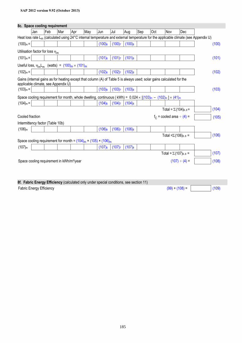
SAP 2012 version 9.92 (October 2013)
185
8c. Space cooling requirement Jan Feb Mar Apr May Jun Jul Aug Sep Oct Nov Dec Heat loss rate Lm (calculated using 24°C internal temperature and external temperature for the applicable climate (see Appendix U) (100)m = (100)6 (100)7 (100)8 (100) Utilisation factor for loss ηm (101)m = (101)6 (101)7 (101)8 (101) Useful loss, ηmLm (watts) = (100)m × (101)m
(102)m = (102)6 (102)7 (102)8 (102) Gains (internal gains as for heating except that column (A) of Table 5 is always used; solar gains calculated for the applicable climate, see Appendix U)
(103)m = (103)6 (103)7 (103)8 (103) Space cooling requirement for month, whole dwelling, continuous ( kWh) = 0.024 × [(103)m – (102)m ] × (41)m (104)m = (104)6 (104)7 (104)8 Total = Σ(104)6..8 = (104) Cooled fraction fC = cooled area ÷ (4) = (105) Intermittency factor (Table 10b) (106)m (106)6 (106)7 (106)8 Total =Σ(106)6..8 = (106) Space cooling requirement for month = (104)m × (105) × (106)m (107)m (107)6 (107)7 (107)8 Total = Σ(107)6..8 = (107) Space cooling requirement in kWh/m²/year (107) ÷ (4) = (108)
8f. Fabric Energy Efficiency (calculated only under special conditions, see section 11) Fabric Energy Efficiency (99) + (108) = (109)
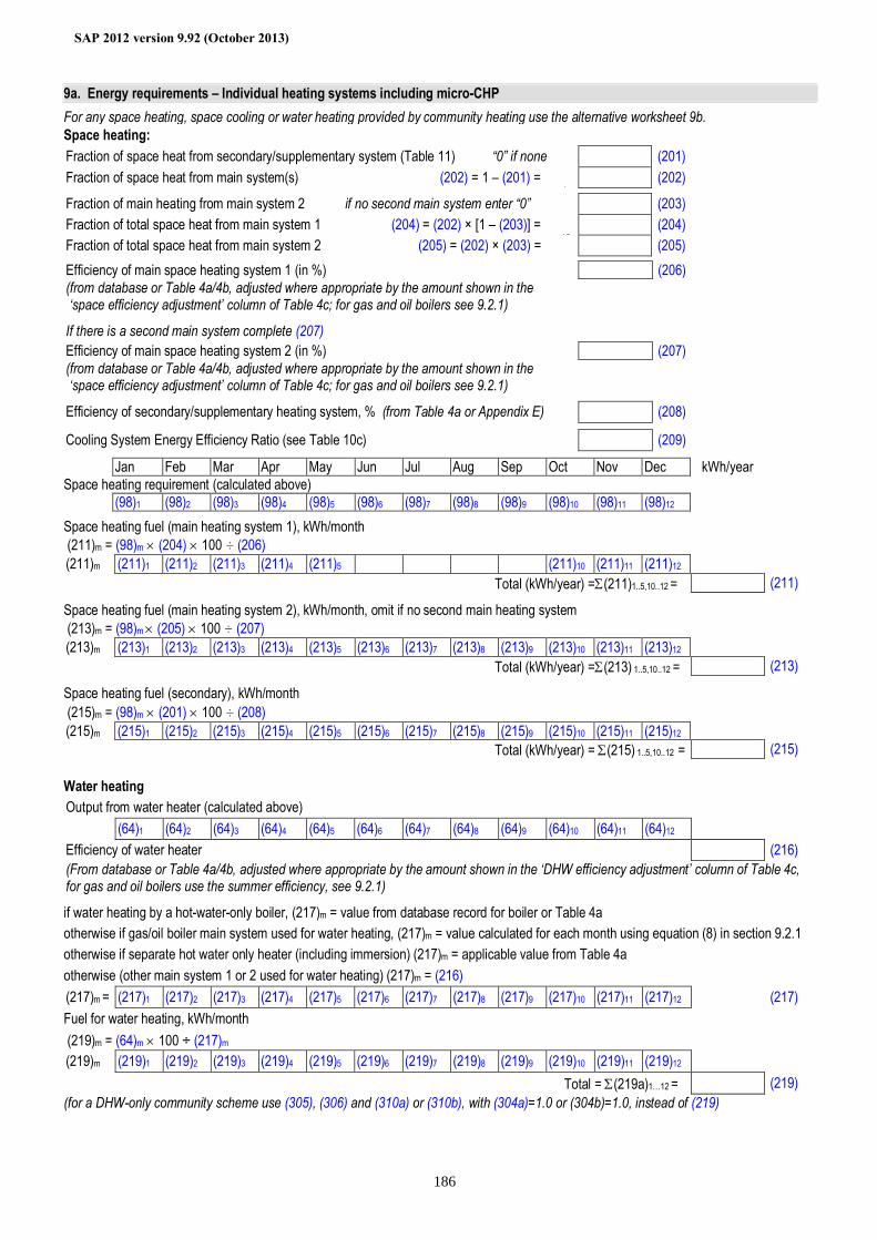
SAP 2012 version 9.92 (October 2013)
186
9a. Energy requirements – Individual heating systems including micro-CHP For any space heating, space cooling or water heating provided by community heating use the alternative worksheet 9b. Space heating: Fraction of space heat from secondary/supplementary system (Table 11) “0” if none (201) Fraction of space heat from main system(s) (202) = 1 – (201) =
1 (202)
Fraction of main heating from main system 2 if no second main system enter “0” (203) Fraction of total space heat from main system 1 (204) = (202) × [1 – (203)] =
(2 (204)
Fraction of total space heat from main system 2 (205) = (202) × (203) = (2
(205) Efficiency of main space heating system 1 (in %) (206) (from database or Table 4a/4b, adjusted where appropriate by the amount shown in the ‘space efficiency adjustment’ column of Table 4c; for gas and oil boilers see 9.2.1) If there is a second main system complete (207) Efficiency of main space heating system 2 (in %) (207) (from database or Table 4a/4b, adjusted where appropriate by the amount shown in the ‘space efficiency adjustment’ column of Table 4c; for gas and oil boilers see 9.2.1) Efficiency of secondary/supplementary heating system, % (from Table 4a or Appendix E) (208) Cooling System Energy Efficiency Ratio (see Table 10c) (209) Jan Feb Mar Apr May Jun Jul Aug Sep Oct Nov Dec kWh/year Space heating requirement (calculated above) (98)1 (98)2 (98)3 (98)4 (98)5 (98)6 (98)7 (98)8 (98)9 (98)10 (98)11 (98)12 Space heating fuel (main heating system 1), kWh/month (211)m = (98)m × (204) × 100 ÷ (206) (211)m (211)1 (211)2 (211)3 (211)4 (211)5 (211)10 (211)11 (211)12 Total (kWh/year) =Σ(211)1..5,10..12 = (211) Space heating fuel (main heating system 2), kWh/month, omit if no second main heating system (213)m = (98)m × (205) × 100 ÷ (207) (213)m (213)1 (213)2 (213)3 (213)4 (213)5 (213)6 (213)7 (213)8 (213)9 (213)10 (213)11 (213)12 Total (kWh/year) =Σ(213) 1..5,10..12 = (213) Space heating fuel (secondary), kWh/month (215)m = (98)m × (201) × 100 ÷ (208) (215)m (215)1 (215)2 (215)3 (215)4 (215)5 (215)6 (215)7 (215)8 (215)9 (215)10 (215)11 (215)12 Total (kWh/year) = Σ(215) 1..5,10..12 = (215)
Water heating Output from water heater (calculated above) (64)1 (64)2 (64)3 (64)4 (64)5 (64)6 (64)7 (64)8 (64)9 (64)10 (64)11 (64)12 Efficiency of water heater (216) (From database or Table 4a/4b, adjusted where appropriate by the amount shown in the ‘DHW efficiency adjustment’ column of Table 4c, for gas and oil boilers use the summer efficiency, see 9.2.1) if water heating by a hot-water-only boiler, (217)m = value from database record for boiler or Table 4a otherwise if gas/oil boiler main system used for water heating, (217)m = value calculated for each month using equation (8) in section 9.2.1 otherwise if separate hot water only heater (including immersion) (217)m = applicable value from Table 4a otherwise (other main system 1 or 2 used for water heating) (217)m = (216) (217)m = (217)1 (217)2 (217)3 (217)4 (217)5 (217)6 (217)7 (217)8 (217)9 (217)10 (217)11 (217)12 (217) Fuel for water heating, kWh/month (219)m = (64)m × 100 ÷ (217)m (219)m (219)1 (219)2 (219)3 (219)4 (219)5 (219)6 (219)7 (219)8 (219)9 (219)10 (219)11 (219)12 Total = Σ(219a)1…12 = (219) (for a DHW-only community scheme use (305), (306) and (310a) or (310b), with (304a)=1.0 or (304b)=1.0, instead of (219)
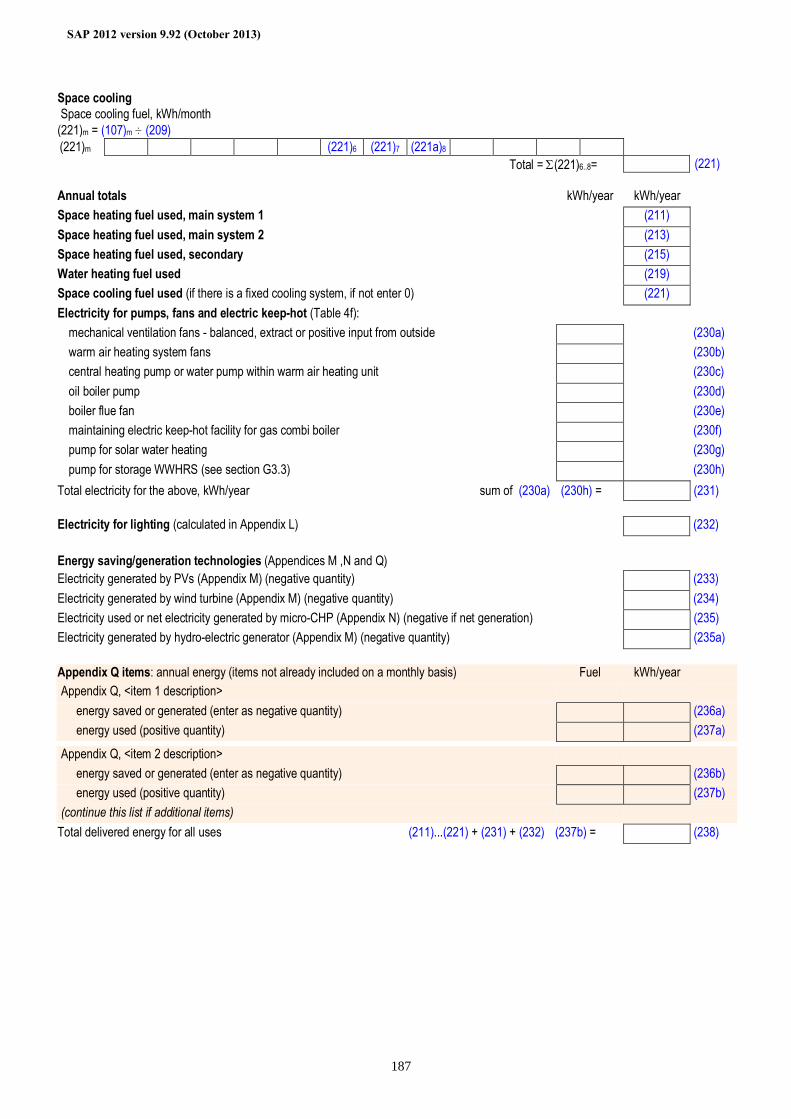
SAP 2012 version 9.92 (October 2013)
187
Space cooling Space cooling fuel, kWh/month (221)m = (107)m ÷ (209) (221)m (221)6 (221)7 (221a)8 Total = Σ(221)6..8= (221)
Annual totals kWh/year kWh/year Space heating fuel used, main system 1 (211) Space heating fuel used, main system 2 (213) Space heating fuel used, secondary (215) Water heating fuel used (219) Space cooling fuel used (if there is a fixed cooling system, if not enter 0) (221) Electricity for pumps, fans and electric keep-hot (Table 4f):
mechanical ventilation fans - balanced, extract or positive input from outside (230a) warm air heating system fans (230b) central heating pump or water pump within warm air heating unit (230c) oil boiler pump (230d) boiler flue fan (230e) maintaining electric keep-hot facility for gas combi boiler (230f) pump for solar water heating (230g) pump for storage WWHRS (see section G3.3) (230h)
Total electricity for the above, kWh/year sum of (230a)…(230h) = (231) Electricity for lighting (calculated in Appendix L) (232) Energy saving/generation technologies (Appendices M ,N and Q) Electricity generated by PVs (Appendix M) (negative quantity) (233) Electricity generated by wind turbine (Appendix M) (negative quantity) (234) Electricity used or net electricity generated by micro-CHP (Appendix N) (negative if net generation) (235) Electricity generated by hydro-electric generator (Appendix M) (negative quantity) (235a) Appendix Q items: annual energy (items not already included on a monthly basis) Fuel kWh/year Appendix Q, <item 1 description> energy saved or generated (enter as negative quantity) (236a) energy used (positive quantity) (237a)
Appendix Q, <item 2 description> energy saved or generated (enter as negative quantity) (236b) energy used (positive quantity) (237b) (continue this list if additional items)
Total delivered energy for all uses (211)...(221) + (231) + (232)…(237b) = (238)
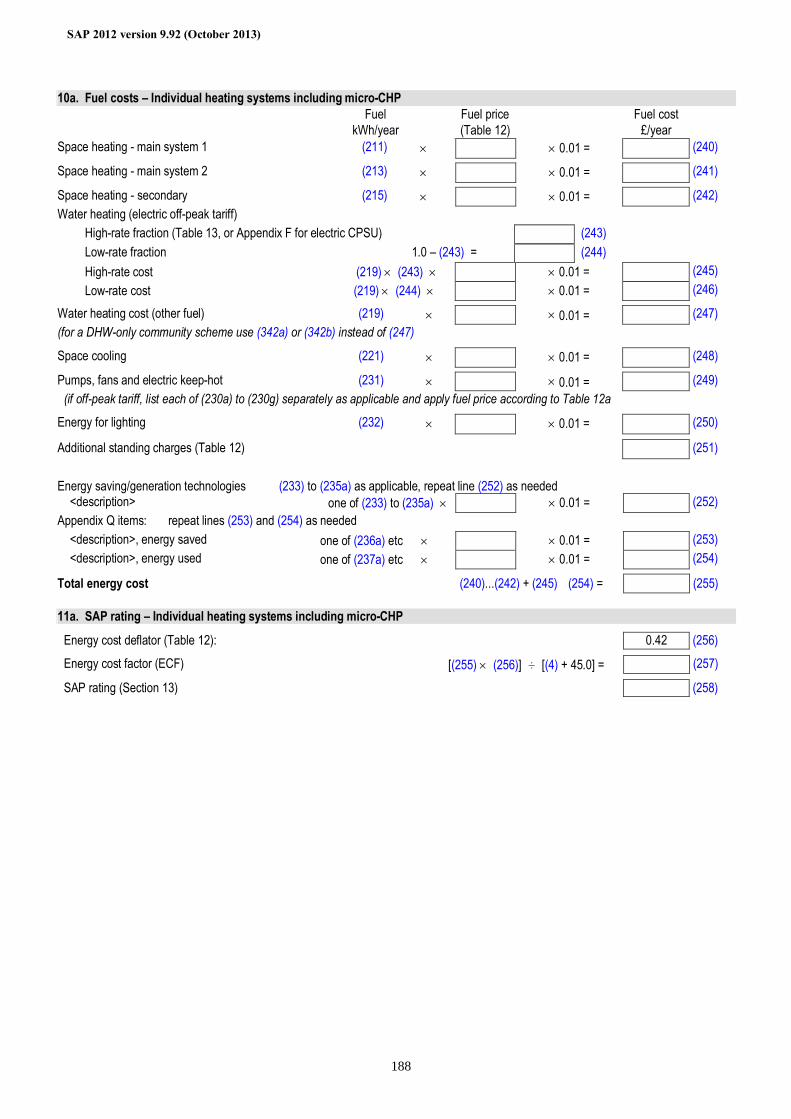
SAP 2012 version 9.92 (October 2013)
188
10a. Fuel costs – Individual heating systems including micro-CHP Fuel
required Fuel price Fuel cost
kWh/year (Table 12) £/year Space heating - main system 1 (211) × × 0.01 = (240) Space heating - main system 2 (213) × × 0.01 = (241) Space heating - secondary (215) × × 0.01 = (242) Water heating (electric off-peak tariff) High-rate fraction (Table 13, or Appendix F for electric CPSU) (243) Low-rate fraction 1.0 – (243) = (244) High-rate cost (219) × (243) × × 0.01 = (245) Low-rate cost (219) × (244) × × 0.01 = (246) Water heating cost (other fuel) (219) × × 0.01 = (247) (for a DHW-only community scheme use (342a) or (342b) instead of (247) Space cooling (221) × × 0.01 = (248) Pumps, fans and electric keep-hot (231) × × 0.01 = (249) (if off-peak tariff, list each of (230a) to (230g) separately as applicable and apply fuel price according to Table 12a Energy for lighting (232) × × 0.01 = (250) Additional standing charges (Table 12) (251)
Energy saving/generation technologies (233) to (235a) as applicable, repeat line (252) as needed <description> one of (233) to (235a) × × 0.01 = (252) Appendix Q items: repeat lines (253) and (254) as needed <description>, energy saved one of (236a) etc × × 0.01 = (253) <description>, energy used one of (237a) etc × × 0.01 = (254) Total energy cost (240)...(242) + (245)…(254) = (255)
11a. SAP rating – Individual heating systems including micro-CHP Energy cost deflator (Table 12): 0.42 (256) Energy cost factor (ECF) [(255) × (256)] ÷ [(4) + 45.0] = (257) SAP rating (Section 13) (258)
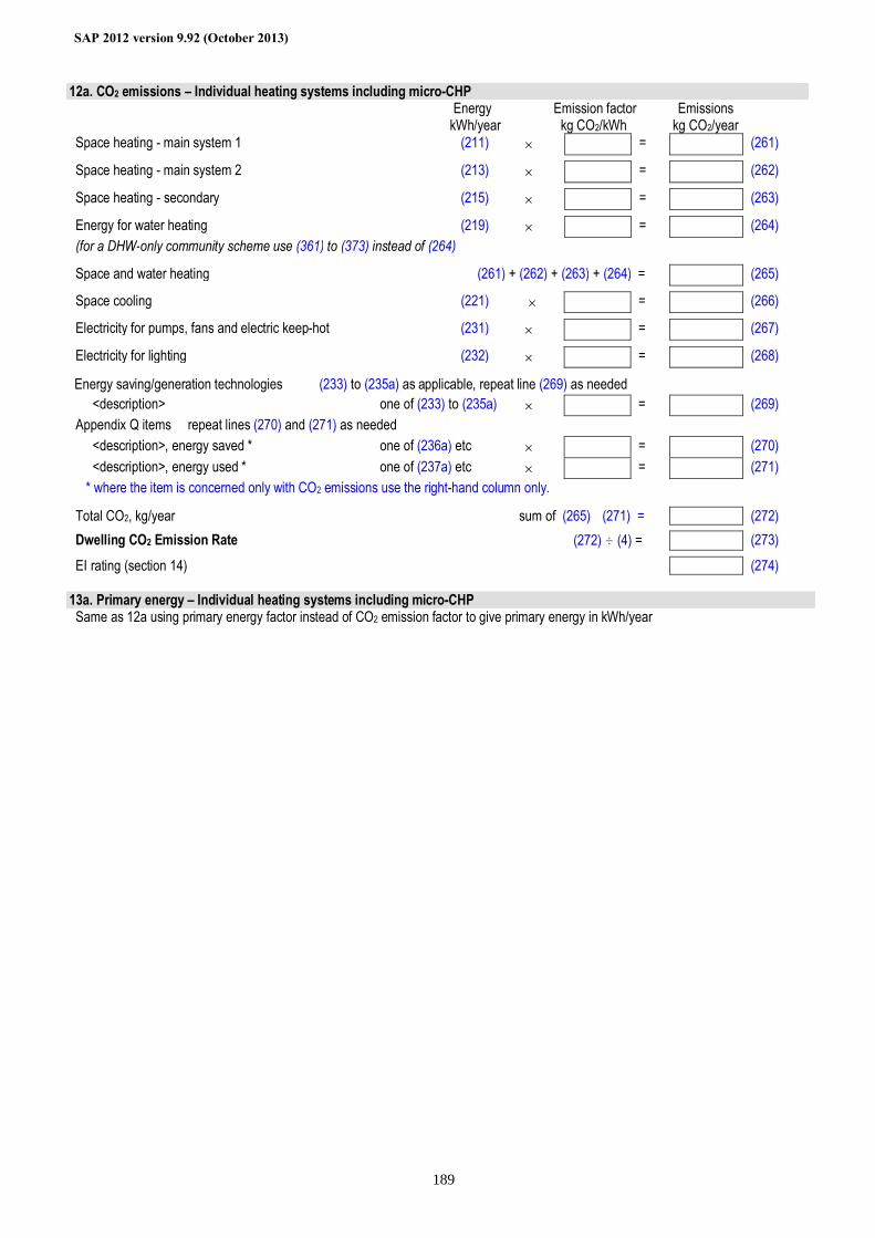
SAP 2012 version 9.92 (October 2013)
189
12a. CO2 emissions – Individual heating systems including micro-CHP
Energy kWh/year
Emission factor kg CO2/kWh
Emissions kg CO2/year
Space heating - main system 1 (211) × = (261) Space heating - main system 2 (213) × = (262) Space heating - secondary (215) × = (263) Energy for water heating (219) × = (264) (for a DHW-only community scheme use (361) to (373) instead of (264) Space and water heating (261) + (262) + (263) + (264) = (265) Space cooling (221) × = (266) Electricity for pumps, fans and electric keep-hot (231) × = (267) Electricity for lighting (232) × = (268) Energy saving/generation technologies (233) to (235a) as applicable, repeat line (269) as needed <description> one of (233) to (235a) × = (269) Appendix Q items repeat lines (270) and (271) as needed <description>, energy saved * one of (236a) etc × = (270) <description>, energy used * one of (237a) etc × = (271) * where the item is concerned only with CO2 emissions use the right-hand column only. Total CO2, kg/year sum of (265)…(271) = (272) Dwelling CO2 Emission Rate (272) ÷ (4) = (273) EI rating (section 14) (274)
13a. Primary energy – Individual heating systems including micro-CHP Same as 12a using primary energy factor instead of CO2 emission factor to give primary energy in kWh/year
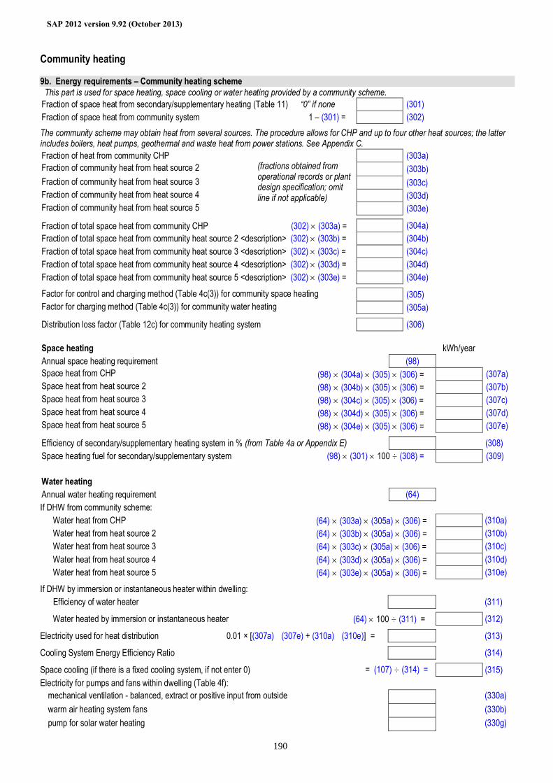
SAP 2012 version 9.92 (October 2013)
190
Community heating 9b. Energy requirements – Community heating scheme This part is used for space heating, space cooling or water heating provided by a community scheme. Fraction of space heat from secondary/supplementary heating (Table 11) “0” if none (301) Fraction of space heat from community system 1 – (301) = (302) The community scheme may obtain heat from several sources. The procedure allows for CHP and up to four other heat sources; the latter includes boilers, heat pumps, geothermal and waste heat from power stations. See Appendix C. Fraction of heat from community CHP (303a) Fraction of community heat from heat source 2 (303b) Fraction of community heat from heat source 3 (303c) Fraction of community heat from heat source 4 (303d) Fraction of community heat from heat source 5
(fractions obtained from operational records or plant design specification; omit line if not applicable)
(303e) Fraction of total space heat from community CHP (302) × (303a) = (304a) Fraction of total space heat from community heat source 2 <description> (302) × (303b) = (304b) Fraction of total space heat from community heat source 3 <description> (302) × (303c) = (304c) Fraction of total space heat from community heat source 4 <description> (302) × (303d) = (304d) Fraction of total space heat from community heat source 5 <description> (302) × (303e) = (304e) Factor for control and charging method (Table 4c(3)) for community space heating (305) Factor for charging method (Table 4c(3)) for community water heating (305a) Distribution loss factor (Table 12c) for community heating system (306)
Space heating kWh/year Annual space heating requirement (98) Space heat from CHP (98) × (304a) × (305) × (306) = (307a) Space heat from heat source 2 (98) × (304b) × (305) × (306) = (307b) Space heat from heat source 3 (98) × (304c) × (305) × (306) = (307c) Space heat from heat source 4 (98) × (304d) × (305) × (306) = (307d) Space heat from heat source 5 (98) × (304e) × (305) × (306) = (307e) Efficiency of secondary/supplementary heating system in % (from Table 4a or Appendix E) (308) Space heating fuel for secondary/supplementary system (98) × (301) × 100 ÷ (308) = (309) Water heating Annual water heating requirement (64) If DHW from community scheme: Water heat from CHP (64) × (303a) × (305a) × (306) = (310a) Water heat from heat source 2 (64) × (303b) × (305a) × (306) = (310b) Water heat from heat source 3 (64) × (303c) × (305a) × (306) = (310c) Water heat from heat source 4 (64) × (303d) × (305a) × (306) = (310d) Water heat from heat source 5 (64) × (303e) × (305a) × (306) = (310e) If DHW by immersion or instantaneous heater within dwelling: Efficiency of water heater (311) Water heated by immersion or instantaneous heater (64) × 100 ÷ (311) = (312) Electricity used for heat distribution 0.01 × [(307a)…(307e) + (310a)…(310e)] = (313) Cooling System Energy Efficiency Ratio (314) Space cooling (if there is a fixed cooling system, if not enter 0) = (107) ÷ (314) = (315) Electricity for pumps and fans within dwelling (Table 4f):
mechanical ventilation - balanced, extract or positive input from outside (330a) warm air heating system fans (330b) pump for solar water heating (330g)
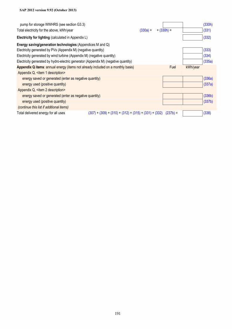
SAP 2012 version 9.92 (October 2013)
191
pump for storage WWHRS (see section G3.3) (330h) Total electricity for the above, kWh/year (330a) + … + (330h) = (331)
Electricity for lighting (calculated in Appendix L) (332) Energy saving/generation technologies (Appendices M and Q) Electricity generated by PVs (Appendix M) (negative quantity) (333) Electricity generated by wind turbine (Appendix M) (negative quantity) (334) Electricity generated by hydro-electric generator (Appendix M) (negative quantity) (335a) Appendix Q items: annual energy (items not already included on a monthly basis) Fuel kWh/year Appendix Q, <item 1 description> energy saved or generated (enter as negative quantity) (336a) energy used (positive quantity) (337a) Appendix Q, <item 2 description> energy saved or generated (enter as negative quantity) (336b) energy used (positive quantity) (337b) (continue this list if additional items)
Total delivered energy for all uses (307) + (309) + (310) + (312) + (315) + (331) + (332)…(237b) = (338)
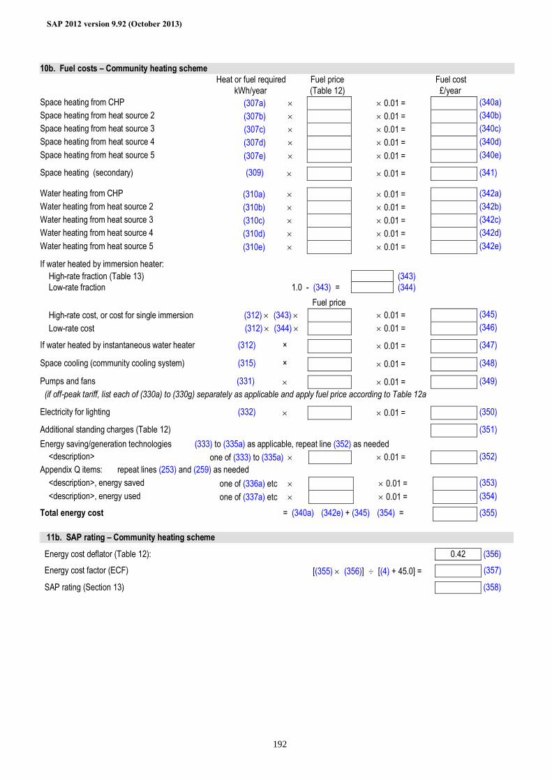
SAP 2012 version 9.92 (October 2013)
192
10b. Fuel costs – Community heating scheme Heat or fuel required Fuel price Fuel cost kWh/year (Table 12) £/year Space heating from CHP (307a) × × 0.01 = (340a) Space heating from heat source 2 (307b) × × 0.01 = (340b) Space heating from heat source 3 (307c) × × 0.01 = (340c) Space heating from heat source 4 (307d) × × 0.01 = (340d) Space heating from heat source 5 (307e) × × 0.01 = (340e) Space heating (secondary) (309) × × 0.01 = (341) Water heating from CHP (310a) × × 0.01 = (342a) Water heating from heat source 2 (310b) × × 0.01 = (342b) Water heating from heat source 3 (310c) × × 0.01 = (342c) Water heating from heat source 4 (310d) × × 0.01 = (342d) Water heating from heat source 5 (310e) × × 0.01 = (342e) If water heated by immersion heater: High-rate fraction (Table 13) (343) Low-rate fraction 1.0 - (343) = (344) Fuel price High-rate cost, or cost for single immersion (312) × (343) × × 0.01 = (345) Low-rate cost (312) × (344) × × 0.01 = (346) If water heated by instantaneous water heater (312) × × 0.01 = (347) Space cooling (community cooling system) (315) × × 0.01 = (348) Pumps and fans (331) × × 0.01 = (349) (if off-peak tariff, list each of (330a) to (330g) separately as applicable and apply fuel price according to Table 12a Electricity for lighting (332) × × 0.01 = (350) Additional standing charges (Table 12) (351) Energy saving/generation technologies (333) to (335a) as applicable, repeat line (352) as needed <description> one of (333) to (335a) × × 0.01 = (352) Appendix Q items: repeat lines (253) and (259) as needed <description>, energy saved one of (336a) etc × × 0.01 = (353) <description>, energy used one of (337a) etc × × 0.01 = (354) Total energy cost = (340a)…(342e) + (345)…(354) = (355)
11b. SAP rating – Community heating scheme Energy cost deflator (Table 12): 0.42 (356) Energy cost factor (ECF) [(355) × (356)] ÷ [(4) + 45.0] = (357) SAP rating (Section 13) (358)
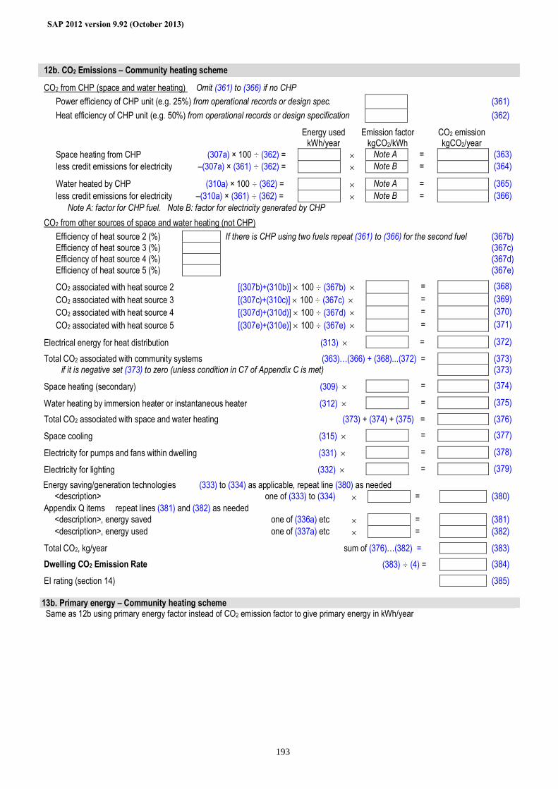
SAP 2012 version 9.92 (October 2013)
193
12b. CO2 Emissions – Community heating scheme
CO2 from CHP (space and water heating) Omit (361) to (366) if no CHP Power efficiency of CHP unit (e.g. 25%) from operational records or design spec. (361) Heat efficiency of CHP unit (e.g. 50%) from operational records or design specification (362)
Energy used kWh/year
Emission factor kgCO2/kWh CO2 emission
kgCO2/year
Space heating from CHP (307a) × 100 ÷ (362) = × Note A = (363) less credit emissions for electricity –(307a) × (361) ÷ (362) = × Note B = (364)
Water heated by CHP (310a) × 100 ÷ (362) = × Note A = (365) less credit emissions for electricity –(310a) × (361) ÷ (362) = × Note B = (366)
Note A: factor for CHP fuel. Note B: factor for electricity generated by CHP
CO2 from other sources of space and water heating (not CHP) Efficiency of heat source 2 (%) If there is CHP using two fuels repeat (361) to (366) for the second fuel (367b) Efficiency of heat source 3 (%) (367c) Efficiency of heat source 4 (%) (367d) Efficiency of heat source 5 (%) (367e)
CO2 associated with heat source 2 [(307b)+(310b)] × 100 ÷ (367b) × = (368) CO2 associated with heat source 3 [(307c)+(310c)] × 100 ÷ (367c) × = (369) CO2 associated with heat source 4 [(307d)+(310d)] × 100 ÷ (367d) × = (370) CO2 associated with heat source 5 [(307e)+(310e)] × 100 ÷ (367e) × = (371)
Electrical energy for heat distribution (313) × = (372)
Total CO2 associated with community systems (363)…(366) + (368)...(372) = (373) if it is negative set (373) to zero (unless condition in C7 of Appendix C is met) (373)
Space heating (secondary) (309) × = (374)
Water heating by immersion heater or instantaneous heater (312) × = (375)
Total CO2 associated with space and water heating (373) + (374) + (375) = (376)
Space cooling (315) × = (377)
Electricity for pumps and fans within dwelling (331) × = (378)
Electricity for lighting (332) × = (379)
Energy saving/generation technologies (333) to (334) as applicable, repeat line (380) as needed <description> one of (333) to (334) × = (380) Appendix Q items repeat lines (381) and (382) as needed <description>, energy saved one of (336a) etc × = (381) <description>, energy used one of (337a) etc × = (382)
Total CO2, kg/year sum of (376)…(382) = (383)
Dwelling CO2 Emission Rate (383) ÷ (4) = (384)
EI rating (section 14) (385)
13b. Primary energy – Community heating scheme Same as 12b using primary energy factor instead of CO2 emission factor to give primary energy in kWh/year
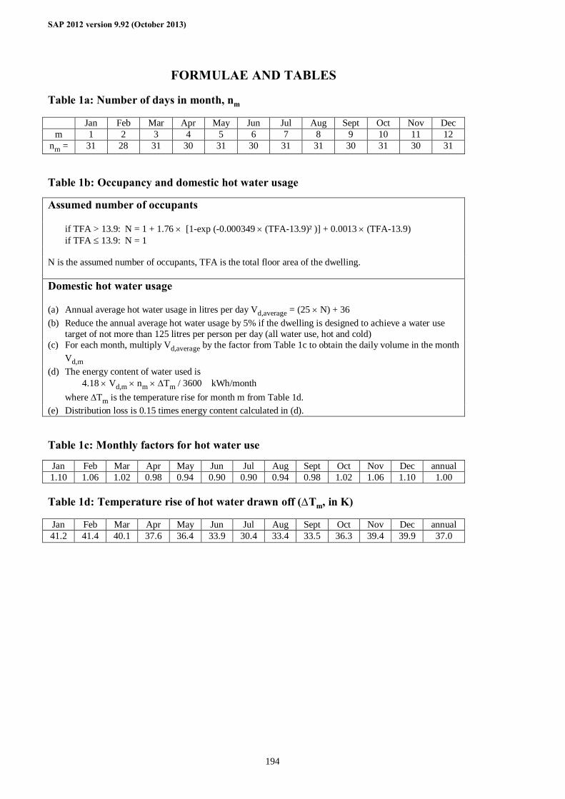
SAP 2012 version 9.92 (October 2013)
194
FORMULAE AND TABLES Table 1a: Number of days in month, nm
Jan Feb Mar Apr May Jun Jul Aug Sept Oct Nov Dec m 1 2 3 4 5 6 7 8 9 10 11 12
nm = 31 28 31 30 31 30 31 31 30 31 30 31 Table 1b: Occupancy and domestic hot water usage
Assumed number of occupants
if TFA > 13.9: N = 1 + 1.76 × [1-exp (-0.000349 × (TFA-13.9)² )] + 0.0013 × (TFA-13.9) if TFA ≤ 13.9: N = 1 N is the assumed number of occupants, TFA is the total floor area of the dwelling. Domestic hot water usage
(a) Annual average hot water usage in litres per day Vd,average = (25 × N) + 36 (b) Reduce the annual average hot water usage by 5% if the dwelling is designed to achieve a water use
target of not more than 125 litres per person per day (all water use, hot and cold) (c) For each month, multiply Vd,average by the factor from Table 1c to obtain the daily volume in the month
Vd,m (d) The energy content of water used is
4.18 × Vd,m × nm × ∆Tm / 3600 kWh/month where ∆Tm is the temperature rise for month m from Table 1d.
(e) Distribution loss is 0.15 times energy content calculated in (d). Table 1c: Monthly factors for hot water use
Jan Feb Mar Apr May Jun Jul Aug Sept Oct Nov Dec annual 1.10 1.06 1.02 0.98 0.94 0.90 0.90 0.94 0.98 1.02 1.06 1.10 1.00 Table 1d: Temperature rise of hot water drawn off (∆Tm, in K)
Jan Feb Mar Apr May Jun Jul Aug Sept Oct Nov Dec annual 41.2 41.4 40.1 37.6 36.4 33.9 30.4 33.4 33.5 36.3 39.4 39.9 37.0
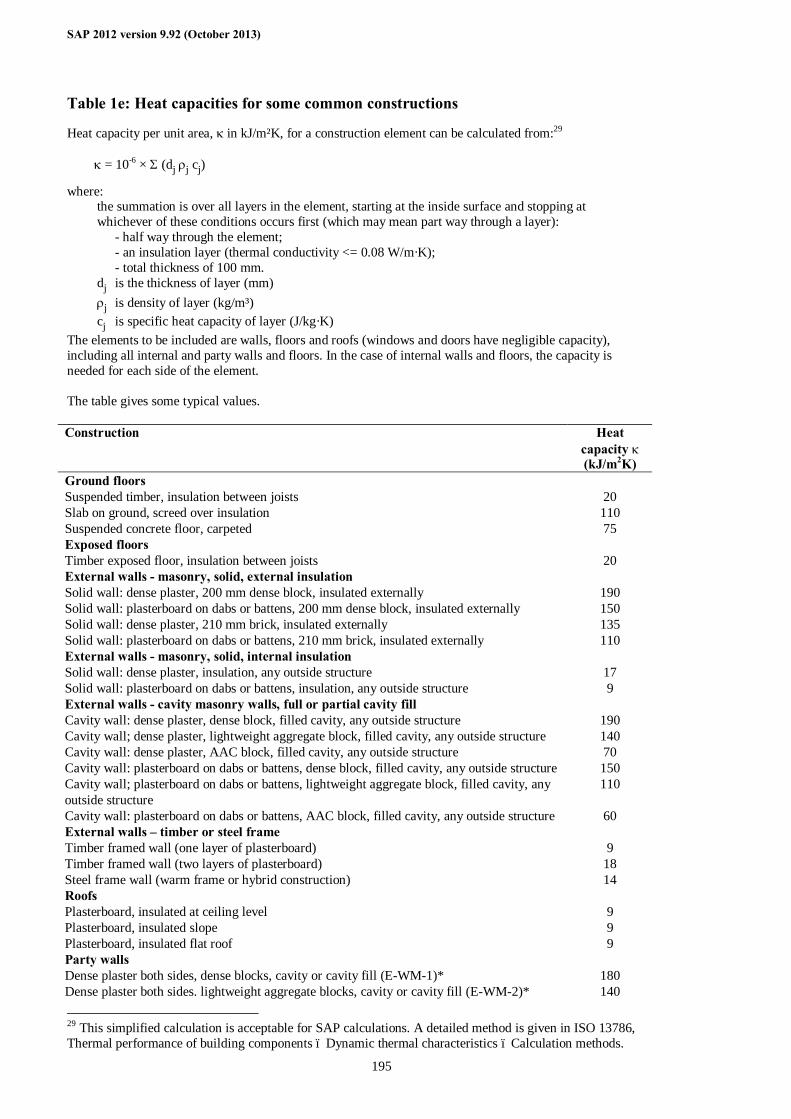
SAP 2012 version 9.92 (October 2013)
195
Table 1e: Heat capacities for some common constructions
Heat capacity per unit area, κ in kJ/m²K, for a construction element can be calculated from:29
κ = 10-6 × Σ (dj ρj cj)
where: the summation is over all layers in the element, starting at the inside surface and stopping at whichever of these conditions occurs first (which may mean part way through a layer): - half way through the element; - an insulation layer (thermal conductivity <= 0.08 W/m·K); - total thickness of 100 mm. dj is the thickness of layer (mm) ρj is density of layer (kg/m³) cj is specific heat capacity of layer (J/kg·K)
The elements to be included are walls, floors and roofs (windows and doors have negligible capacity), including all internal and party walls and floors. In the case of internal walls and floors, the capacity is needed for each side of the element. The table gives some typical values. Construction Heat
capacity κ (kJ/m2K)
Ground floors Suspended timber, insulation between joists 20 Slab on ground, screed over insulation 110 Suspended concrete floor, carpeted 75 Exposed floors Timber exposed floor, insulation between joists 20 External walls - masonry, solid, external insulation Solid wall: dense plaster, 200 mm dense block, insulated externally 190 Solid wall: plasterboard on dabs or battens, 200 mm dense block, insulated externally 150 Solid wall: dense plaster, 210 mm brick, insulated externally 135 Solid wall: plasterboard on dabs or battens, 210 mm brick, insulated externally 110 External walls - masonry, solid, internal insulation Solid wall: dense plaster, insulation, any outside structure 17 Solid wall: plasterboard on dabs or battens, insulation, any outside structure 9 External walls - cavity masonry walls, full or partial cavity fill Cavity wall: dense plaster, dense block, filled cavity, any outside structure 190 Cavity wall; dense plaster, lightweight aggregate block, filled cavity, any outside structure 140 Cavity wall: dense plaster, AAC block, filled cavity, any outside structure 70 Cavity wall: plasterboard on dabs or battens, dense block, filled cavity, any outside structure 150 Cavity wall; plasterboard on dabs or battens, lightweight aggregate block, filled cavity, any outside structure
110
Cavity wall: plasterboard on dabs or battens, AAC block, filled cavity, any outside structure 60 External walls – timber or steel frame Timber framed wall (one layer of plasterboard) 9 Timber framed wall (two layers of plasterboard) 18 Steel frame wall (warm frame or hybrid construction) 14 Roofs Plasterboard, insulated at ceiling level 9 Plasterboard, insulated slope 9 Plasterboard, insulated flat roof 9 Party walls Dense plaster both sides, dense blocks, cavity or cavity fill (E-WM-1)* 180 Dense plaster both sides. lightweight aggregate blocks, cavity or cavity fill (E-WM-2)* 140 29 This simplified calculation is acceptable for SAP calculations. A detailed method is given in ISO 13786, Thermal performance of building components – Dynamic thermal characteristics – Calculation methods.
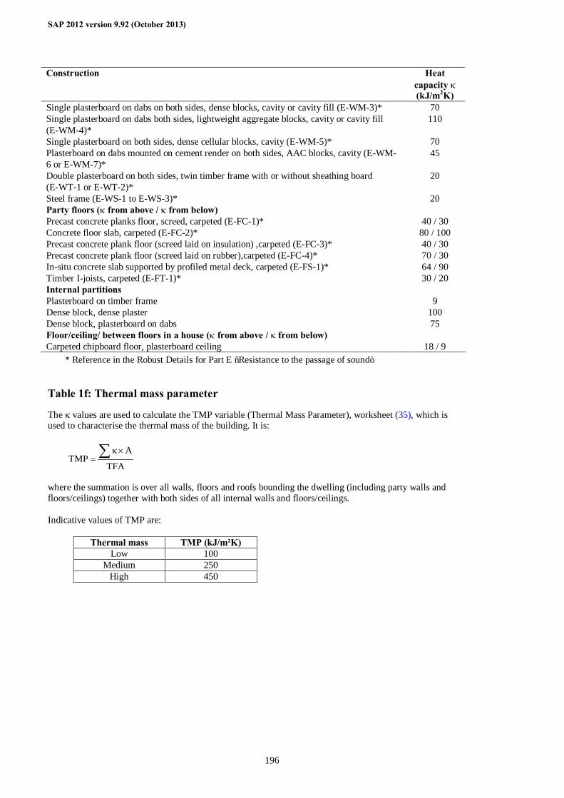
SAP 2012 version 9.92 (October 2013)
196
Construction Heat capacity κ (kJ/m2K)
Single plasterboard on dabs on both sides, dense blocks, cavity or cavity fill (E-WM-3)* 70 Single plasterboard on dabs both sides, lightweight aggregate blocks, cavity or cavity fill (E-WM-4)*
110
Single plasterboard on both sides, dense cellular blocks, cavity (E-WM-5)* 70 Plasterboard on dabs mounted on cement render on both sides, AAC blocks, cavity (E-WM-6 or E-WM-7)*
45
Double plasterboard on both sides, twin timber frame with or without sheathing board (E-WT-1 or E-WT-2)*
20
Steel frame (E-WS-1 to E-WS-3)* 20 Party floors (κ from above / κ from below) Precast concrete planks floor, screed, carpeted (E-FC-1)* 40 / 30 Concrete floor slab, carpeted (E-FC-2)* 80 / 100 Precast concrete plank floor (screed laid on insulation) ,carpeted (E-FC-3)* 40 / 30 Precast concrete plank floor (screed laid on rubber),carpeted (E-FC-4)* 70 / 30 In-situ concrete slab supported by profiled metal deck, carpeted (E-FS-1)* 64 / 90 Timber I-joists, carpeted (E-FT-1)* 30 / 20 Internal partitions Plasterboard on timber frame 9 Dense block, dense plaster 100 Dense block, plasterboard on dabs 75 Floor/ceiling/ between floors in a house (κ from above / κ from below) Carpeted chipboard floor, plasterboard ceiling 18 / 9
* Reference in the Robust Details for Part E “Resistance to the passage of sound” Table 1f: Thermal mass parameter
The κ values are used to calculate the TMP variable (Thermal Mass Parameter), worksheet (35), which is used to characterise the thermal mass of the building. It is:
TFA
ATMP ∑ ×κ
=
where the summation is over all walls, floors and roofs bounding the dwelling (including party walls and floors/ceilings) together with both sides of all internal walls and floors/ceilings. Indicative values of TMP are:
Thermal mass TMP (kJ/m²K) Low 100
Medium 250 High 450
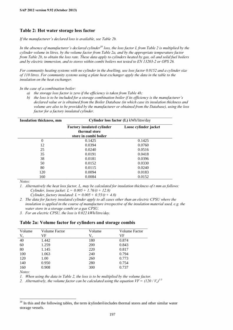
SAP 2012 version 9.92 (October 2013)
197
Table 2: Hot water storage loss factor
If the manufacturer’s declared loss is available, see Table 2b. In the absence of manufacturer’s declared cylinder30 loss, the loss factor L from Table 2 is multiplied by the cylinder volume in litres, by the volume factor from Table 2a, and by the appropriate temperature factor from Table 2b, to obtain the loss rate. These data apply to cylinders heated by gas, oil and solid fuel boilers and by electric immersion, and to stores within combi boilers not tested to EN 13203-2 or OPS 26. For community heating systems with no cylinder in the dwelling, use loss factor 0.0152 and a cylinder size of 110 litres. For community systems using a plate heat exchanger apply the data in the table to the insulation on the heat exchanger. In the case of a combination boiler:
a) the storage loss factor is zero if the efficiency is taken from Table 4b; b) the loss is to be included for a storage combination boiler if its efficiency is the manufacturer’s
declared value or is obtained from the Boiler Database (in which case its insulation thickness and volume are also to be provided by the manufacturer or obtained from the Database), using the loss factor for a factory insulated cylinder.
Cylinder loss factor (L) kWh/litre/day Insulation thickness, mm
Factory insulated cylinder thermal store
store in combi boiler
Loose cylinder jacket
0 0.1425 0.1425 12 0.0394 0.0760 25 0.0240 0.0516 35 0.0191 0.0418 38 0.0181 0.0396 50 0.0152 0.0330 80 0.0115 0.0240
120 0.0094 0.0183 160 0.0084 0.0152
Notes: 1. Alternatively the heat loss factor, L, may be calculated for insulation thickness of t mm as follows: Cylinder, loose jacket: L = 0.005 + 1.76/(t + 12.8) Cylinder, factory insulated: L = 0.005 + 0.55/(t + 4.0) 2. The data for factory insulated cylinder apply to all cases other than an electric CPSU where the
insulation is applied in the course of manufacture irrespective of the insulation material used, e.g. the water store in a storage combi or a gas CPSU.
3. For an electric CPSU, the loss is 0.022 kWh/litre/day. Table 2a: Volume factor for cylinders and storage combis
Volume Vc
Volume Factor VF
Volume Vc
Volume Factor VF
40 1.442 180 0.874 60 1.259 200 0.843 80 1.145 220 0.817 100 1.063 240 0.794 120 1.00 260 0.773 140 0.950 280 0.754 160 0.908 300 0.737 Notes: 1. When using the data in Table 2, the loss is to be multiplied by the volume factor. 2. Alternatively, the volume factor can be calculated using the equation VF = (120 / Vc)1/3
30 In this and the following tables, the term ‘cylinder’ includes thermal stores and other similar water storage vessels.
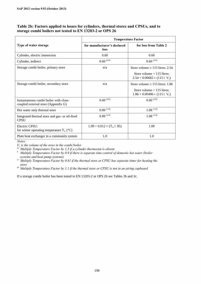
SAP 2012 version 9.92 (October 2013)
198
Table 2b: Factors applied to losses for cylinders, thermal stores and CPSUs, and to storage combi boilers not tested to EN 13203-2 or OPS 26
Temperature Factor
Type of water storage for manufacturer’s declared loss
for loss from Table 2
Cylinder, electric immersion 0.60 0.60
Cylinder, indirect 0.60 a) b) 0.60 a) b)
Storage combi boiler, primary store n/a Store volume ≥ 115 litres: 2.54
Store volume < 115 litres: 2.54 + 0.00682 × (115 – Vc)
Storage combi boiler, secondary store n/a Store volume ≥ 115 litres: 1.86
Store volume < 115 litres: 1.86 + 0.00496 × (115 – Vc)
Instantaneous combi boiler with close-coupled external store (Appendix G)
0.60 a) b) 0.60 a) b)
Hot water only thermal store 0.89 c) d) 1.08 c) d)
Integrated thermal store and gas- or oil-fired CPSU
0.89 c) d) 1.08 c) d)
Electric CPSU: for winter operating temperature Tw (°C)
1.09 + 0.012 × (Tw – 85) 1.00
Plate heat exchanger in a community system 1.0 1.0 Notes: Vc is the volume of the store in the combi boiler a) Multiply Temperature Factor by 1.3 if a cylinder thermostat is absent. b Multiply Temperature Factor by 0.9 if there is separate time control of domestic hot water (boiler
systems and heat pump systems) c) Multiply Temperature Factor by 0.81 if the thermal store or CPSU has separate timer for heating the
store d) Multiply Temperature Factor by 1.1 if the thermal store or CPSU is not in an airing cupboard If a storage combi boiler has been tested to EN 13203-2 or OPS 26 see Tables 3b and 3c.
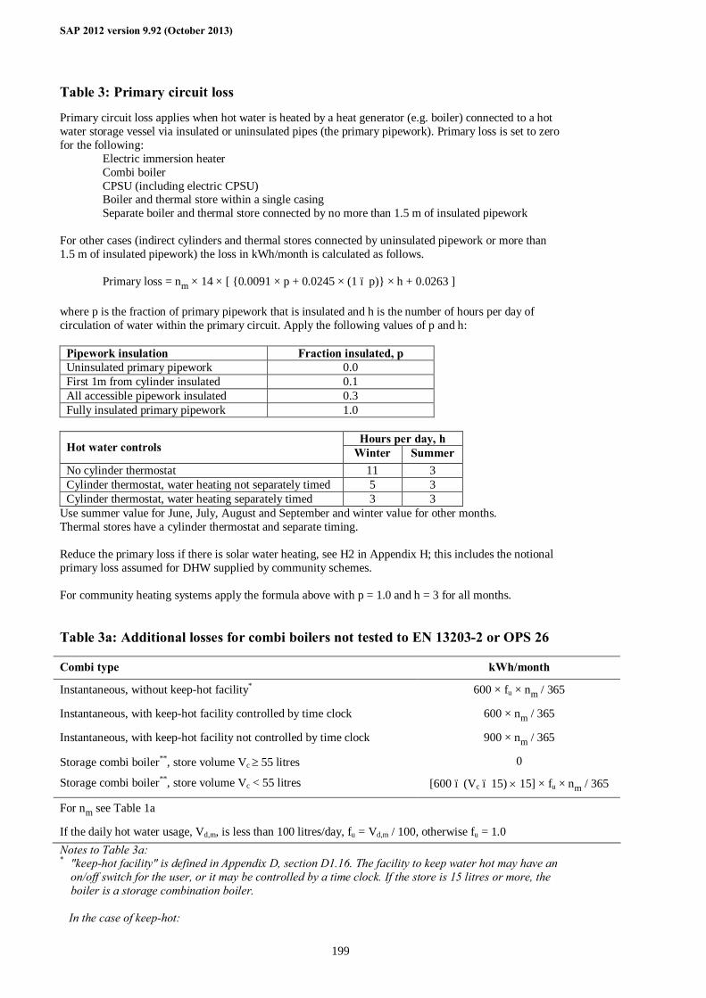
SAP 2012 version 9.92 (October 2013)
199
Table 3: Primary circuit loss
Primary circuit loss applies when hot water is heated by a heat generator (e.g. boiler) connected to a hot water storage vessel via insulated or uninsulated pipes (the primary pipework). Primary loss is set to zero for the following:
Electric immersion heater Combi boiler CPSU (including electric CPSU) Boiler and thermal store within a single casing Separate boiler and thermal store connected by no more than 1.5 m of insulated pipework
For other cases (indirect cylinders and thermal stores connected by uninsulated pipework or more than 1.5 m of insulated pipework) the loss in kWh/month is calculated as follows. Primary loss = nm × 14 × [ {0.0091 × p + 0.0245 × (1 – p)} × h + 0.0263 ] where p is the fraction of primary pipework that is insulated and h is the number of hours per day of circulation of water within the primary circuit. Apply the following values of p and h:
Pipework insulation Fraction insulated, p Uninsulated primary pipework 0.0 First 1m from cylinder insulated 0.1 All accessible pipework insulated 0.3 Fully insulated primary pipework 1.0
Hours per day, h
Hot water controls Winter Summer No cylinder thermostat 11 3 Cylinder thermostat, water heating not separately timed 5 3 Cylinder thermostat, water heating separately timed 3 3
Use summer value for June, July, August and September and winter value for other months. Thermal stores have a cylinder thermostat and separate timing. Reduce the primary loss if there is solar water heating, see H2 in Appendix H; this includes the notional primary loss assumed for DHW supplied by community schemes. For community heating systems apply the formula above with p = 1.0 and h = 3 for all months. Table 3a: Additional losses for combi boilers not tested to EN 13203-2 or OPS 26
Combi type kWh/month
Instantaneous, without keep-hot facility* 600 × fu × nm / 365
Instantaneous, with keep-hot facility controlled by time clock 600 × nm / 365
Instantaneous, with keep-hot facility not controlled by time clock 900 × nm / 365
Storage combi boiler**, store volume Vc ≥ 55 litres 0
Storage combi boiler**, store volume Vc < 55 litres [600 – (Vc – 15) × 15] × fu × nm / 365
For nm see Table 1a
If the daily hot water usage, Vd,m, is less than 100 litres/day, fu = Vd,m / 100, otherwise fu = 1.0 Notes to Table 3a: * "keep-hot facility" is defined in Appendix D, section D1.16. The facility to keep water hot may have an
on/off switch for the user, or it may be controlled by a time clock. If the store is 15 litres or more, the boiler is a storage combination boiler.
In the case of keep-hot:
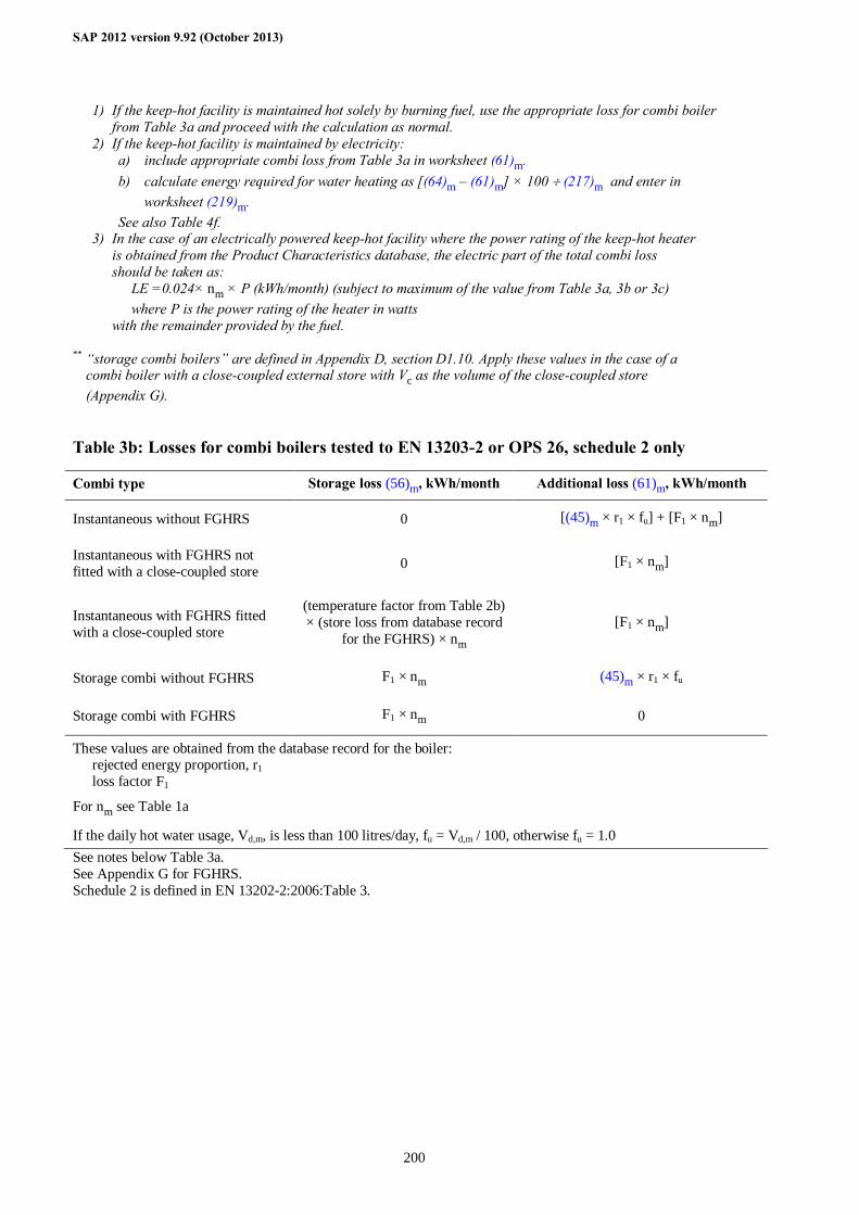
SAP 2012 version 9.92 (October 2013)
200
1) If the keep-hot facility is maintained hot solely by burning fuel, use the appropriate loss for combi boiler from Table 3a and proceed with the calculation as normal.
2) If the keep-hot facility is maintained by electricity: a) include appropriate combi loss from Table 3a in worksheet (61)m. b) calculate energy required for water heating as [(64)m – (61)m] × 100 ÷ (217)m and enter in
worksheet (219)m. See also Table 4f.
3) In the case of an electrically powered keep-hot facility where the power rating of the keep-hot heater is obtained from the Product Characteristics database, the electric part of the total combi loss should be taken as:
LE =0.024× nm × P (kWh/month) (subject to maximum of the value from Table 3a, 3b or 3c) where P is the power rating of the heater in watts
with the remainder provided by the fuel.
** “storage combi boilers” are defined in Appendix D, section D1.10. Apply these values in the case of a combi boiler with a close-coupled external store with Vc as the volume of the close-coupled store (Appendix G).
Table 3b: Losses for combi boilers tested to EN 13203-2 or OPS 26, schedule 2 only
Combi type Storage loss (56)m, kWh/month Additional loss (61)m, kWh/month
Instantaneous without FGHRS 0 [(45)m × r1 × fu] + [F1 × nm]
Instantaneous with FGHRS not fitted with a close-coupled store 0 [F1 × nm]
Instantaneous with FGHRS fitted with a close-coupled store
(temperature factor from Table 2b) × (store loss from database record
for the FGHRS) × nm [F1 × nm]
Storage combi without FGHRS F1 × nm (45)m × r1 × fu
Storage combi with FGHRS F1 × nm 0
These values are obtained from the database record for the boiler: rejected energy proportion, r1 loss factor F1
For nm see Table 1a
If the daily hot water usage, Vd,m, is less than 100 litres/day, fu = Vd,m / 100, otherwise fu = 1.0 See notes below Table 3a. See Appendix G for FGHRS. Schedule 2 is defined in EN 13202-2:2006:Table 3.
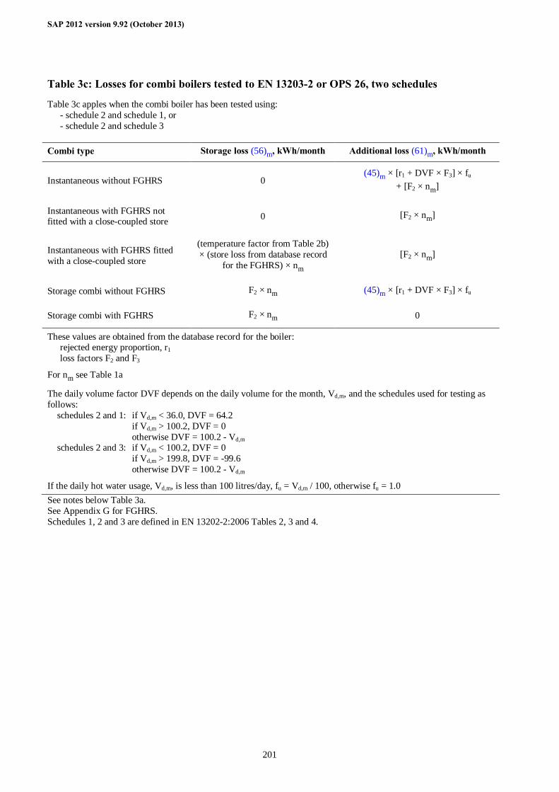
SAP 2012 version 9.92 (October 2013)
201
Table 3c: Losses for combi boilers tested to EN 13203-2 or OPS 26, two schedules
Table 3c apples when the combi boiler has been tested using: - schedule 2 and schedule 1, or - schedule 2 and schedule 3
Combi type Storage loss (56)m, kWh/month Additional loss (61)m, kWh/month
Instantaneous without FGHRS 0 (45)m × [r1 + DVF × F3] × fu
+ [F2 × nm]
Instantaneous with FGHRS not fitted with a close-coupled store 0 [F2 × nm]
Instantaneous with FGHRS fitted with a close-coupled store
(temperature factor from Table 2b) × (store loss from database record
for the FGHRS) × nm [F2 × nm]
Storage combi without FGHRS F2 × nm (45)m × [r1 + DVF × F3] × fu
Storage combi with FGHRS F2 × nm 0
These values are obtained from the database record for the boiler: rejected energy proportion, r1 loss factors F2 and F3
For nm see Table 1a
The daily volume factor DVF depends on the daily volume for the month, Vd,m, and the schedules used for testing as follows: schedules 2 and 1: if Vd,m < 36.0, DVF = 64.2 if Vd,m > 100.2, DVF = 0 otherwise DVF = 100.2 - Vd,m schedules 2 and 3: if Vd,m < 100.2, DVF = 0 if Vd,m > 199.8, DVF = -99.6 otherwise DVF = 100.2 - Vd,m
If the daily hot water usage, Vd,m, is less than 100 litres/day, fu = Vd,m / 100, otherwise fu = 1.0 See notes below Table 3a. See Appendix G for FGHRS. Schedules 1, 2 and 3 are defined in EN 13202-2:2006 Tables 2, 3 and 4.
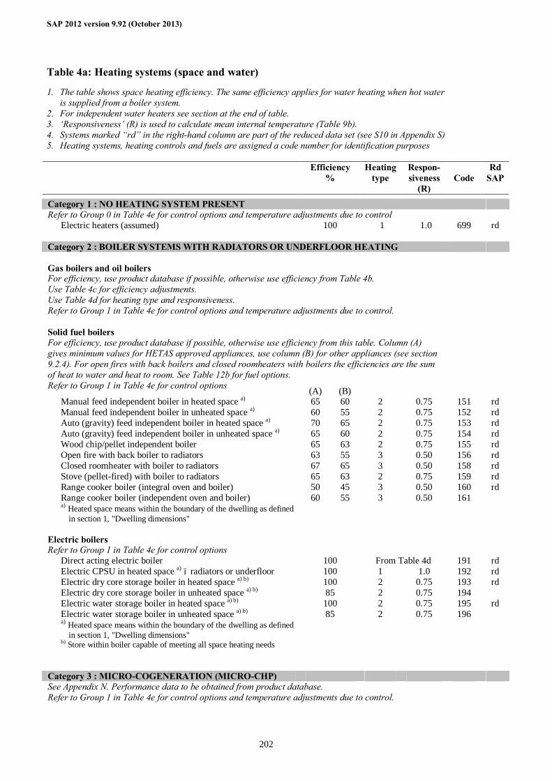
SAP 2012 version 9.92 (October 2013)
202
Table 4a: Heating systems (space and water)
1. The table shows space heating efficiency. The same efficiency applies for water heating when hot water is supplied from a boiler system.
2. For independent water heaters see section at the end of table. 3. ‘Responsiveness’ (R) is used to calculate mean internal temperature (Table 9b). 4. Systems marked “rd” in the right-hand column are part of the reduced data set (see S10 in Appendix S) 5. Heating systems, heating controls and fuels are assigned a code number for identification purposes
Efficiency %
Heating type
Respon-siveness
(R) Code
Rd SAP
Category 1 : NO HEATING SYSTEM PRESENT Refer to Group 0 in Table 4e for control options and temperature adjustments due to control
Electric heaters (assumed) 100 1 1.0 699 rd Category 2 : BOILER SYSTEMS WITH RADIATORS OR UNDERFLOOR HEATING Gas boilers and oil boilers For efficiency, use product database if possible, otherwise use efficiency from Table 4b. Use Table 4c for efficiency adjustments. Use Table 4d for heating type and responsiveness. Refer to Group 1 in Table 4e for control options and temperature adjustments due to control.
Solid fuel boilers For efficiency, use product database if possible, otherwise use efficiency from this table. Column (A) gives minimum values for HETAS approved appliances, use column (B) for other appliances (see section 9.2.4). For open fires with back boilers and closed roomheaters with boilers the efficiencies are the sum of heat to water and heat to room. See Table 12b for fuel options.
Refer to Group 1 in Table 4e for control options (A) (B)
Manual feed independent boiler in heated space a) 65 60 2 0.75 151 rd Manual feed independent boiler in unheated space a) 60 55 2 0.75 152 rd Auto (gravity) feed independent boiler in heated space a) 70 65 2 0.75 153 rd Auto (gravity) feed independent boiler in unheated space a) 65 60 2 0.75 154 rd Wood chip/pellet independent boiler 65 63 2 0.75 155 rd Open fire with back boiler to radiators 63 55 3 0.50 156 rd Closed roomheater with boiler to radiators 67 65 3 0.50 158 rd Stove (pellet-fired) with boiler to radiators 65 63 2 0.75 159 rd Range cooker boiler (integral oven and boiler) 50 45 3 0.50 160 rd Range cooker boiler (independent oven and boiler) 60 55 3 0.50 161 a) Heated space means within the boundary of the dwelling as defined
in section 1, "Dwelling dimensions"
Electric boilers Refer to Group 1 in Table 4e for control options
Direct acting electric boiler 100 From Table 4d 191 rd Electric CPSU in heated space a) – radiators or underfloor 100 1 1.0 192 rd Electric dry core storage boiler in heated space a) b) 100 2 0.75 193 rd Electric dry core storage boiler in unheated space a) b) 85 2 0.75 194 Electric water storage boiler in heated space a) b) 100 2 0.75 195 rd Electric water storage boiler in unheated space a) b) 85 2 0.75 196 a) Heated space means within the boundary of the dwelling as defined
in section 1, "Dwelling dimensions" b) Store within boiler capable of meeting all space heating needs
Category 3 : MICRO-COGENERATION (MICRO-CHP) See Appendix N. Performance data to be obtained from product database. Refer to Group 1 in Table 4e for control options and temperature adjustments due to control.
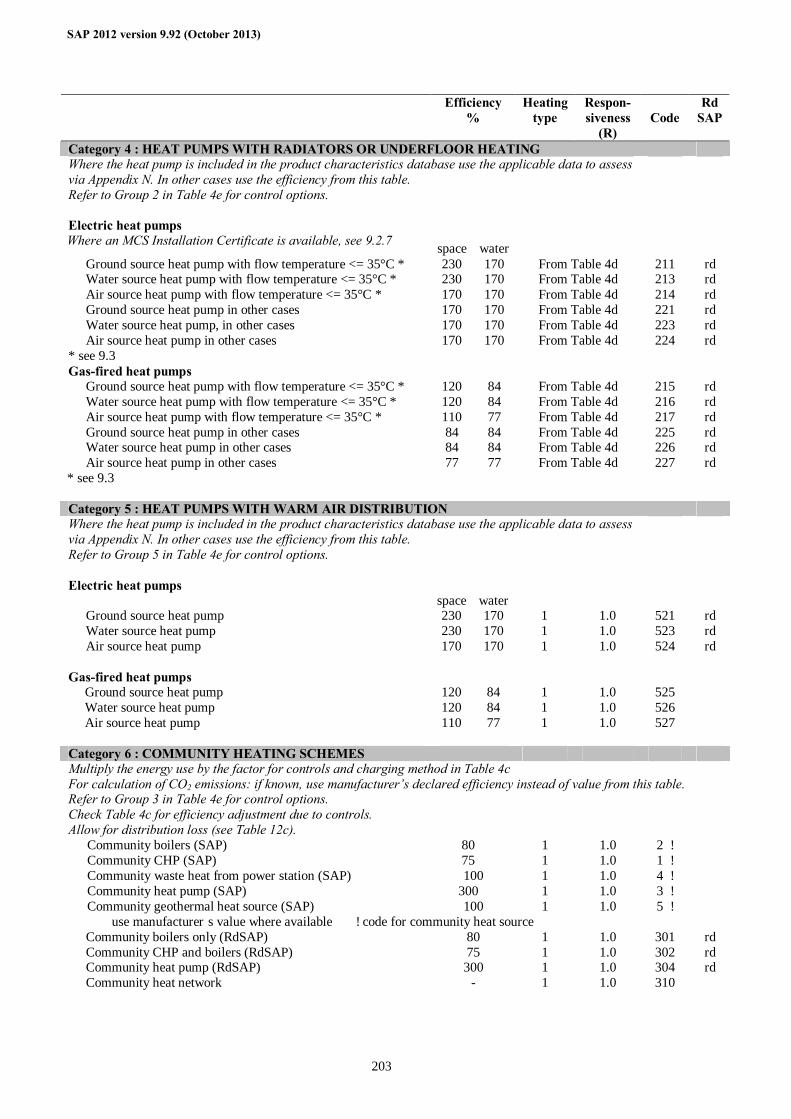
SAP 2012 version 9.92 (October 2013)
203
Efficiency %
Heating type
Respon-siveness
(R) Code
Rd SAP
Category 4 : HEAT PUMPS WITH RADIATORS OR UNDERFLOOR HEATING Where the heat pump is included in the product characteristics database use the applicable data to assess via Appendix N. In other cases use the efficiency from this table.
Refer to Group 2 in Table 4e for control options. Electric heat pumps Where an MCS Installation Certificate is available, see 9.2.7 space water
Ground source heat pump with flow temperature <= 35°C * 230 170 From Table 4d 211 rd Water source heat pump with flow temperature <= 35°C * 230 170 From Table 4d 213 rd Air source heat pump with flow temperature <= 35°C * 170 170 From Table 4d 214 rd Ground source heat pump in other cases 170 170 From Table 4d 221 rd Water source heat pump, in other cases 170 170 From Table 4d 223 rd Air source heat pump in other cases 170 170 From Table 4d 224 rd
* see 9.3 Gas-fired heat pumps
Ground source heat pump with flow temperature <= 35°C * 120 84 From Table 4d 215 rd Water source heat pump with flow temperature <= 35°C * 120 84 From Table 4d 216 rd Air source heat pump with flow temperature <= 35°C * 110 77 From Table 4d 217 rd Ground source heat pump in other cases 84 84 From Table 4d 225 rd Water source heat pump in other cases 84 84 From Table 4d 226 rd Air source heat pump in other cases 77 77 From Table 4d 227 rd
* see 9.3 Category 5 : HEAT PUMPS WITH WARM AIR DISTRIBUTION Where the heat pump is included in the product characteristics database use the applicable data to assess via Appendix N. In other cases use the efficiency from this table.
Refer to Group 5 in Table 4e for control options. Electric heat pumps
space water Ground source heat pump 230 170 1 1.0 521 rd Water source heat pump 230 170 1 1.0 523 rd Air source heat pump 170 170 1 1.0 524 rd
Gas-fired heat pumps
Ground source heat pump 120 84 1 1.0 525 Water source heat pump 120 84 1 1.0 526 Air source heat pump 110 77 1 1.0 527
Category 6 : COMMUNITY HEATING SCHEMES Multiply the energy use by the factor for controls and charging method in Table 4c For calculation of CO2 emissions: if known, use manufacturer’s declared efficiency instead of value from this table. Refer to Group 3 in Table 4e for control options. Check Table 4c for efficiency adjustment due to controls. Allow for distribution loss (see Table 12c).
Community boilers (SAP) 80 † 1 1.0 2 ‡ Community CHP (SAP) 75 † 1 1.0 1 ‡ Community waste heat from power station (SAP) 100 1 1.0 4 ‡ Community heat pump (SAP) 300 † 1 1.0 3 ‡ Community geothermal heat source (SAP) 100 1 1.0 5 ‡
† use manufacturer’s value where available ‡ code for community heat source Community boilers only (RdSAP) 80 1 1.0 301 rd Community CHP and boilers (RdSAP) 75 1 1.0 302 rd Community heat pump (RdSAP) 300 1 1.0 304 rd Community heat network - 1 1.0 310
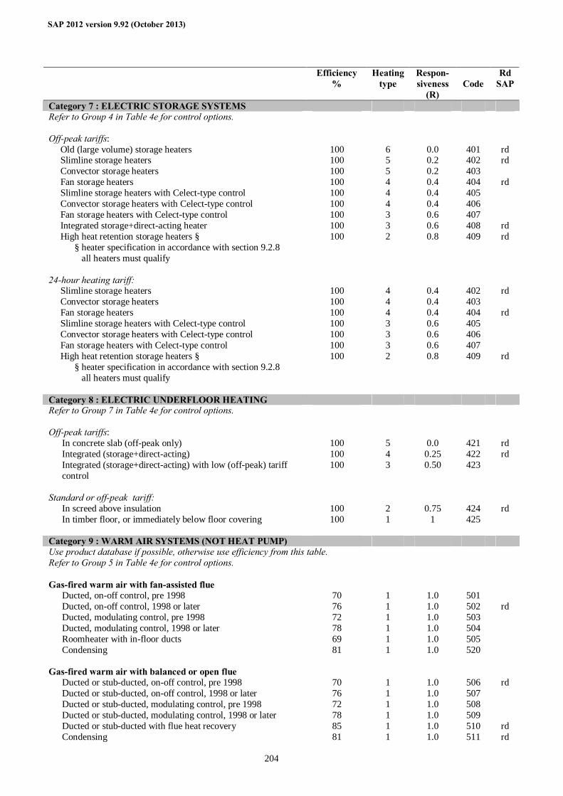
SAP 2012 version 9.92 (October 2013)
204
Efficiency %
Heating type
Respon-siveness
(R) Code
Rd SAP
Category 7 : ELECTRIC STORAGE SYSTEMS Refer to Group 4 in Table 4e for control options. Off-peak tariffs:
Old (large volume) storage heaters 100 6 0.0 401 rd Slimline storage heaters 100 5 0.2 402 rd Convector storage heaters 100 5 0.2 403 Fan storage heaters 100 4 0.4 404 rd Slimline storage heaters with Celect-type control 100 4 0.4 405 Convector storage heaters with Celect-type control 100 4 0.4 406 Fan storage heaters with Celect-type control 100 3 0.6 407 Integrated storage+direct-acting heater 100 3 0.6 408 rd High heat retention storage heaters § 100 2 0.8 409 rd § heater specification in accordance with section 9.2.8 all heaters must qualify
24-hour heating tariff:
Slimline storage heaters 100 4 0.4 402 rd Convector storage heaters 100 4 0.4 403 Fan storage heaters 100 4 0.4 404 rd Slimline storage heaters with Celect-type control 100 3 0.6 405 Convector storage heaters with Celect-type control 100 3 0.6 406 Fan storage heaters with Celect-type control 100 3 0.6 407 High heat retention storage heaters § 100 2 0.8 409 rd § heater specification in accordance with section 9.2.8 all heaters must qualify
Category 8 : ELECTRIC UNDERFLOOR HEATING Refer to Group 7 in Table 4e for control options. Off-peak tariffs:
In concrete slab (off-peak only) 100 5 0.0 421 rd Integrated (storage+direct-acting) 100 4 0.25 422 rd Integrated (storage+direct-acting) with low (off-peak) tariff control
100 3 0.50 423
Standard or off-peak tariff:
In screed above insulation 100 2 0.75 424 rd In timber floor, or immediately below floor covering 100 1 1 425
Category 9 : WARM AIR SYSTEMS (NOT HEAT PUMP) Use product database if possible, otherwise use efficiency from this table. Refer to Group 5 in Table 4e for control options. Gas-fired warm air with fan-assisted flue
Ducted, on-off control, pre 1998 70 1 1.0 501 Ducted, on-off control, 1998 or later 76 1 1.0 502 rd Ducted, modulating control, pre 1998 72 1 1.0 503 Ducted, modulating control, 1998 or later 78 1 1.0 504 Roomheater with in-floor ducts 69 1 1.0 505 Condensing 81 1 1.0 520
Gas-fired warm air with balanced or open flue
Ducted or stub-ducted, on-off control, pre 1998 70 1 1.0 506 rd Ducted or stub-ducted, on-off control, 1998 or later 76 1 1.0 507 Ducted or stub-ducted, modulating control, pre 1998 72 1 1.0 508 Ducted or stub-ducted, modulating control, 1998 or later 78 1 1.0 509 Ducted or stub-ducted with flue heat recovery 85 1 1.0 510 rd Condensing 81 1 1.0 511 rd
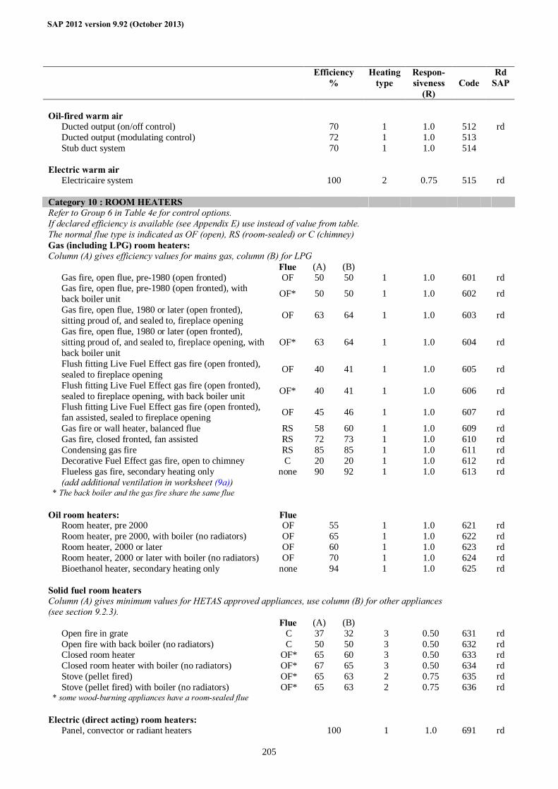
SAP 2012 version 9.92 (October 2013)
205
Efficiency %
Heating type
Respon-siveness
(R) Code
Rd SAP
Oil-fired warm air
Ducted output (on/off control) 70 1 1.0 512 rd Ducted output (modulating control) 72 1 1.0 513 Stub duct system 70 1 1.0 514
Electric warm air
Electricaire system 100 2 0.75 515 rd Category 10 : ROOM HEATERS Refer to Group 6 in Table 4e for control options. If declared efficiency is available (see Appendix E) use instead of value from table. The normal flue type is indicated as OF (open), RS (room-sealed) or C (chimney) Gas (including LPG) room heaters: Column (A) gives efficiency values for mains gas, column (B) for LPG Flue (A) (B)
Gas fire, open flue, pre-1980 (open fronted) OF 50 50 1 1.0 601 rd Gas fire, open flue, pre-1980 (open fronted), with back boiler unit OF* 50 50 1 1.0 602 rd
Gas fire, open flue, 1980 or later (open fronted), sitting proud of, and sealed to, fireplace opening OF 63 64 1 1.0 603 rd
Gas fire, open flue, 1980 or later (open fronted), sitting proud of, and sealed to, fireplace opening, with back boiler unit
OF* 63 64 1 1.0 604 rd
Flush fitting Live Fuel Effect gas fire (open fronted), sealed to fireplace opening OF 40 41 1 1.0 605 rd
Flush fitting Live Fuel Effect gas fire (open fronted), sealed to fireplace opening, with back boiler unit OF* 40 41 1 1.0 606 rd
Flush fitting Live Fuel Effect gas fire (open fronted), fan assisted, sealed to fireplace opening OF 45 46 1 1.0 607 rd
Gas fire or wall heater, balanced flue RS 58 60 1 1.0 609 rd Gas fire, closed fronted, fan assisted RS 72 73 1 1.0 610 rd Condensing gas fire RS 85 85 1 1.0 611 rd Decorative Fuel Effect gas fire, open to chimney C 20 20 1 1.0 612 rd Flueless gas fire, secondary heating only (add additional ventilation in worksheet (9a))
none 90 92 1 1.0 613 rd
* The back boiler and the gas fire share the same flue Oil room heaters: Flue
Room heater, pre 2000 OF 55 1 1.0 621 rd Room heater, pre 2000, with boiler (no radiators) OF 65 1 1.0 622 rd Room heater, 2000 or later OF 60 1 1.0 623 rd Room heater, 2000 or later with boiler (no radiators) OF 70 1 1.0 624 rd Bioethanol heater, secondary heating only none 94 1 1.0 625 rd
Solid fuel room heaters Column (A) gives minimum values for HETAS approved appliances, use column (B) for other appliances (see section 9.2.3).
Flue (A) (B) Open fire in grate C 37 32 3 0.50 631 rd Open fire with back boiler (no radiators) C 50 50 3 0.50 632 rd Closed room heater OF* 65 60 3 0.50 633 rd Closed room heater with boiler (no radiators) OF* 67 65 3 0.50 634 rd Stove (pellet fired) OF* 65 63 2 0.75 635 rd Stove (pellet fired) with boiler (no radiators) OF* 65 63 2 0.75 636 rd
* some wood-burning appliances have a room-sealed flue Electric (direct acting) room heaters:
Panel, convector or radiant heaters 100 1 1.0 691 rd
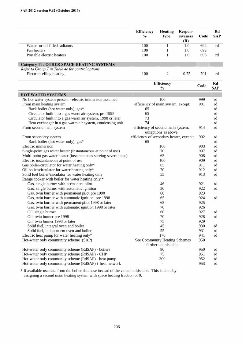
SAP 2012 version 9.92 (October 2013)
206
Efficiency %
Heating type
Respon-siveness
(R) Code
Rd SAP
Water- or oil-filled radiators 100 1 1.0 694 rd Fan heaters 100 1 1.0 692 Portable electric heaters 100 1 1.0 693 rd
Category 11 : OTHER SPACE HEATING SYSTEMS Refer to Group 7 in Table 4e for control options.
Electric ceiling heating 100 2 0.75 701 rd
Efficiency % Code Rd
SAP HOT WATER SYSTEMS
No hot water system present - electric immersion assumed 100 999 rd From main heating system efficiency of main system, except: 901 rd Back boiler (hot water only), gas* 65 rd Circulator built into a gas warm air system, pre 1998 65 rd Circulator built into a gas warm air system, 1998 or later 73 rd Heat exchanger in a gas warm air system, condensing unit 74 rd From second main system efficiency of second main system,
exceptions as above 914 rd
From secondary system efficiency of secondary heater, except: 902 rd Back boiler (hot water only), gas* 65 rd Electric immersion 100 903 rd Single-point gas water heater (instantaneous at point of use) 70 907 rd Multi-point gas water heater (instantaneous serving several taps) 65 908 rd Electric instantaneous at point of use 100 909 rd Gas boiler/circulator for water heating only* 65 911 rd Oil boiler/circulator for water heating only* 70 912 rd Solid fuel boiler/circulator for water heating only 55 913 rd Range cooker with boiler for water heating only:* Gas, single burner with permanent pilot 46 921 rd Gas, single burner with automatic ignition 50 922 rd Gas, twin burner with permanent pilot pre 1998 60 923 Gas, twin burner with automatic ignition pre 1998 65 924 rd Gas, twin burner with permanent pilot 1998 or later 65 925 Gas, twin burner with automatic ignition 1998 or later 70 926 Oil, single burner 60 927 rd Oil, twin burner pre 1998 70 928 rd Oil, twin burner 1998 or later 75 929 Solid fuel, integral oven and boiler 45 930 rd Solid fuel, independent oven and boiler 55 931 rd Electric heat pump for water heating only* 170 941 rd Hot-water only community scheme (SAP) See Community Heating Schemes
further up this table 950
Hot-water only community scheme (RdSAP) - boilers 80 950 rd Hot-water only community scheme (RdSAP) - CHP 75 951 rd Hot-water only community scheme (RdSAP) - heat pump 300 952 rd Hot-water only community scheme (RdSAP) – heat network - 953 rd
* If available use data from the boiler database instead of the value in this table. This is done by assigning a second main heating system with space heating fraction of 0.
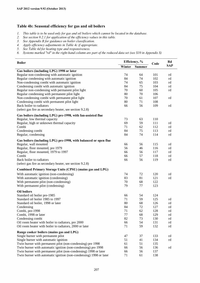
SAP 2012 version 9.92 (October 2013)
207
Table 4b: Seasonal efficiency for gas and oil boilers
1. This table is to be used only for gas and oil boilers which cannot be located in the database. 2. See section 9.2.1 for application of the efficiency values in this table. 3. See Appendix B for guidance on boiler classification. 4. Apply efficiency adjustments in Table 4c if appropriate. 5. See Table 4d for heating type and responsiveness. 6. Systems marked "rd" in the right-hand column are part of the reduced data set (see S10 in Appendix S)
Efficiency, % Boiler Winter Summer
Code Rd SAP
Gas boilers (including LPG) 1998 or later Regular non-condensing with automatic ignition 74 64 101 rd Regular condensing with automatic ignition 84 74 102 rd Non-condensing combi with automatic ignition 74 65 103 rd Condensing combi with automatic ignition 84 75 104 rd Regular non-condensing with permanent pilot light 70 60 105 rd Regular condensing with permanent pilot light 80 70 106 Non-condensing combi with permanent pilot light 70 61 107 rd Condensing combi with permanent pilot light 80 71 108 Back boiler to radiators (select gas fire as secondary heater, see section 9.2.8)
66 56 109 rd
Gas boilers (including LPG) pre-1998, with fan-assisted flue Regular, low thermal capacity 73 63 110 Regular, high or unknown thermal capacity 69 59 111 rd Combi 71 62 112 rd Condensing combi 84 75 113 rd Regular, condensing 84 74 114 rd Gas boilers (including LPG) pre-1998, with balanced or open flue Regular, wall mounted 66 56 115 rd Regular, floor mounted, pre 1979 56 46 116 rd Regular, floor mounted, 1979 to 1997 66 56 117 rd Combi 66 57 118 rd Back boiler to radiators (select gas fire as secondary heater, see section 9.2.8)
66 56 119 rd
Combined Primary Storage Units (CPSU) (mains gas and LPG) With automatic ignition (non-condensing) 74 72 120 rd With automatic ignition (condensing) 83 81 121 rd With permanent pilot (non-condensing) 70 68 122 With permanent pilot (condensing) 79 77 123 Oil boilers Standard oil boiler pre-1985 66 54 124 Standard oil boiler 1985 to 1997 71 59 125 rd Standard oil boiler, 1998 or later 80 68 126 rd Condensing 84 72 127 rd Combi, pre-1998 71 62 128 rd Combi, 1998 or later 77 68 129 rd Condensing combi 82 73 130 rd Oil room heater with boiler to radiators, pre 2000 66 54 131 rd Oil room heater with boiler to radiators, 2000 or later 71 59 132 rd Range cooker boilers (mains gas and LPG) Single burner with permanent pilot 47 37 133 rd Single burner with automatic ignition 51 41 134 rd Twin burner with permanent pilot (non-condensing) pre 1998 61 51 135 Twin burner with automatic ignition (non-condensing) pre 1998 66 56 136 rd Twin burner with permanent pilot (non-condensing) 1998 or later 66 56 137 Twin burner with automatic ignition (non-condensing) 1998 or later 71 61 138
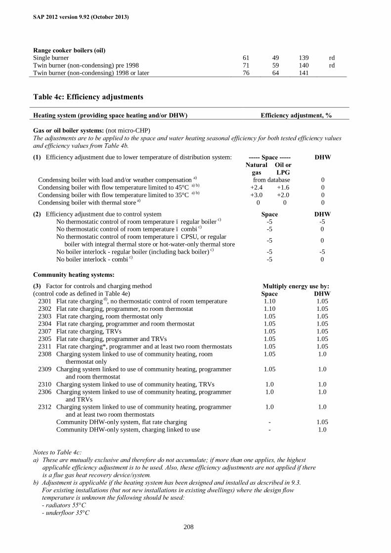
SAP 2012 version 9.92 (October 2013)
208
Range cooker boilers (oil) Single burner 61 49 139 rd Twin burner (non-condensing) pre 1998 71 59 140 rd Twin burner (non-condensing) 1998 or later 76 64 141 Table 4c: Efficiency adjustments
Heating system (providing space heating and/or DHW) Efficiency adjustment, % Gas or oil boiler systems: (not micro-CHP)
The adjustments are to be applied to the space and water heating seasonal efficiency for both tested efficiency values and efficiency values from Table 4b.
(1) Efficiency adjustment due to lower temperature of distribution system: ----- Space ----- DHW Natural
gas Oil or LPG
Condensing boiler with load and/or weather compensation a) from database 0 Condensing boiler with flow temperature limited to 45°C a) b) +2.4 +1.6 0 Condensing boiler with flow temperature limited to 35°C a) b) +3.0 +2.0 0 Condensing boiler with thermal store a) 0 0 0
(2) Efficiency adjustment due to control system Space DHW No thermostatic control of room temperature – regular boiler c) -5 -5 No thermostatic control of room temperature – combi c) -5 0 No thermostatic control of room temperature – CPSU, or regular boiler with integral thermal store or hot-water-only thermal store -5 0
No boiler interlock - regular boiler (including back boiler) c) -5 -5 No boiler interlock - combi c) -5 0 Community heating systems:
(3) Factor for controls and charging method Multiply energy use by: (control code as defined in Table 4e) Space DHW 2301 Flat rate charging d), no thermostatic control of room temperature 1.10 1.05 2302 Flat rate charging, programmer, no room thermostat 1.10 1.05 2303 Flat rate charging, room thermostat only 1.05 1.05 2304 Flat rate charging, programmer and room thermostat 1.05 1.05 2307 Flat rate charging, TRVs 1.05 1.05 2305 Flat rate charging, programmer and TRVs 1.05 1.05 2311 Flat rate charging*, programmer and at least two room thermostats 1.05 1.05 2308 Charging system linked to use of community heating, room
thermostat only 1.05 1.0
2309 Charging system linked to use of community heating, programmer and room thermostat
1.05 1.0
2310 Charging system linked to use of community heating, TRVs 1.0 1.0 2306 Charging system linked to use of community heating, programmer
and TRVs 1.0 1.0
2312 Charging system linked to use of community heating, programmer and at least two room thermostats
1.0 1.0
Community DHW-only system, flat rate charging - 1.05 Community DHW-only system, charging linked to use - 1.0 Notes to Table 4c: a) These are mutually exclusive and therefore do not accumulate; if more than one applies, the highest
applicable efficiency adjustment is to be used. Also, these efficiency adjustments are not applied if there is a flue gas heat recovery device/system.
b) Adjustment is applicable if the heating system has been designed and installed as described in 9.3. For existing installations (but not new installations in existing dwellings) where the design flow temperature is unknown the following should be used: - radiators 55°C - underfloor 35°C
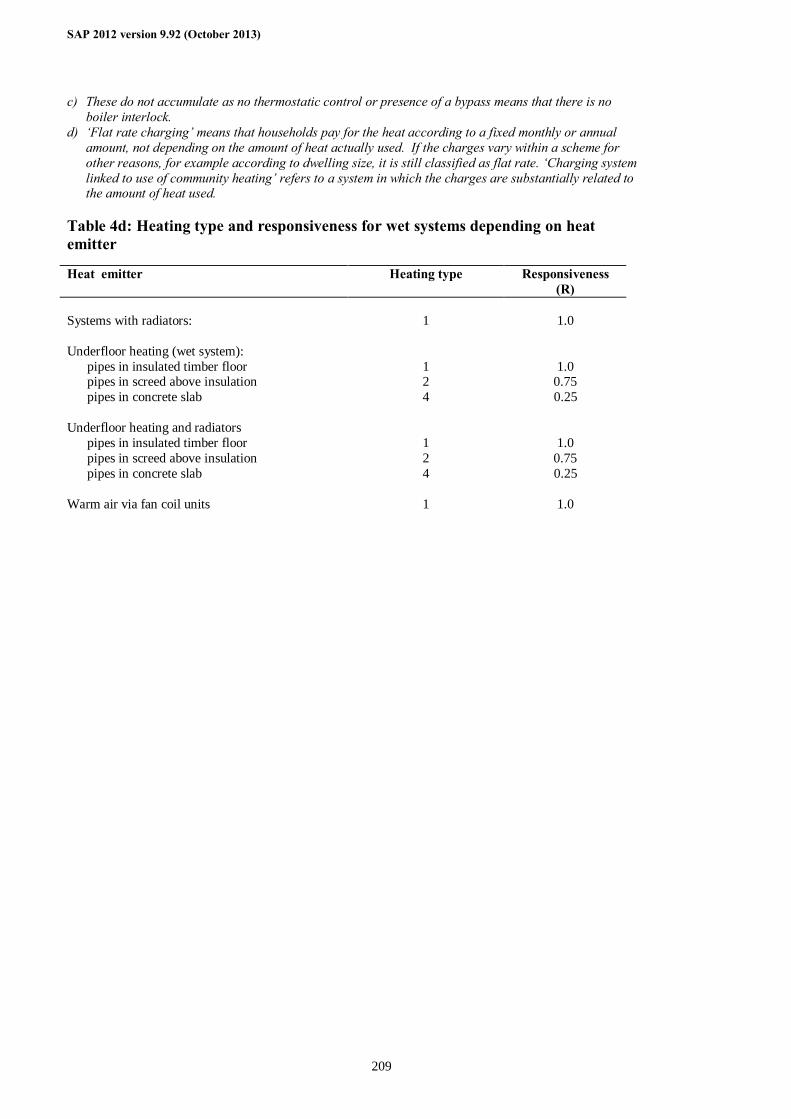
SAP 2012 version 9.92 (October 2013)
209
c) These do not accumulate as no thermostatic control or presence of a bypass means that there is no boiler interlock.
d) ‘Flat rate charging’ means that households pay for the heat according to a fixed monthly or annual amount, not depending on the amount of heat actually used. If the charges vary within a scheme for other reasons, for example according to dwelling size, it is still classified as flat rate. ‘Charging system linked to use of community heating’ refers to a system in which the charges are substantially related to the amount of heat used.
Table 4d: Heating type and responsiveness for wet systems depending on heat emitter
Heat emitter Heating type Responsiveness (R)
Systems with radiators: 1 1.0 Underfloor heating (wet system): pipes in insulated timber floor 1 1.0 pipes in screed above insulation 2 0.75 pipes in concrete slab 4 0.25 Underfloor heating and radiators pipes in insulated timber floor 1 1.0 pipes in screed above insulation 2 0.75 pipes in concrete slab 4 0.25 Warm air via fan coil units 1 1.0
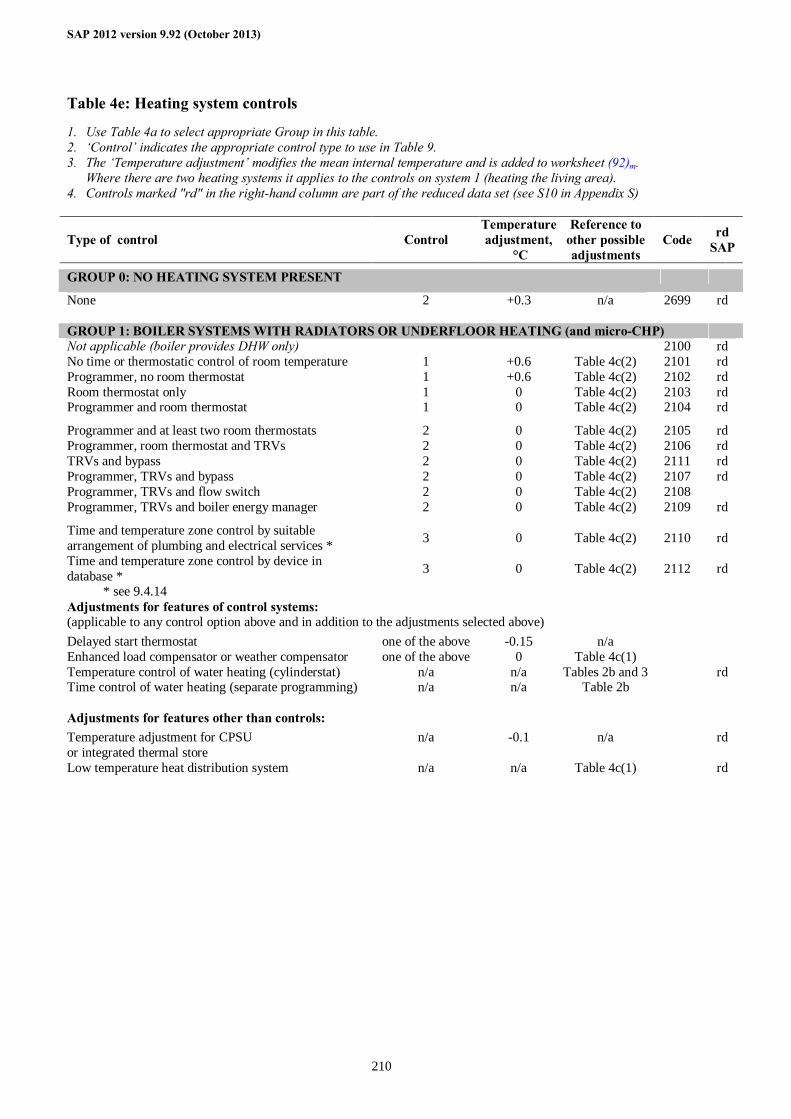
SAP 2012 version 9.92 (October 2013)
210
Table 4e: Heating system controls
1. Use Table 4a to select appropriate Group in this table. 2. ‘Control’ indicates the appropriate control type to use in Table 9. 3. The ‘Temperature adjustment’ modifies the mean internal temperature and is added to worksheet (92)m.
Where there are two heating systems it applies to the controls on system 1 (heating the living area). 4. Controls marked "rd" in the right-hand column are part of the reduced data set (see S10 in Appendix S)
Type of control Control Temperature adjustment,
°C
Reference to other possible adjustments
Code rd SAP
GROUP 0: NO HEATING SYSTEM PRESENT
None 2 +0.3 n/a 2699 rd GROUP 1: BOILER SYSTEMS WITH RADIATORS OR UNDERFLOOR HEATING (and micro-CHP) Not applicable (boiler provides DHW only) 2100 rd No time or thermostatic control of room temperature 1 +0.6 Table 4c(2) 2101 rd Programmer, no room thermostat 1 +0.6 Table 4c(2) 2102 rd Room thermostat only 1 0 Table 4c(2) 2103 rd Programmer and room thermostat 1 0 Table 4c(2) 2104 rd
Programmer and at least two room thermostats 2 0 Table 4c(2) 2105 rd Programmer, room thermostat and TRVs 2 0 Table 4c(2) 2106 rd TRVs and bypass 2 0 Table 4c(2) 2111 rd Programmer, TRVs and bypass 2 0 Table 4c(2) 2107 rd Programmer, TRVs and flow switch 2 0 Table 4c(2) 2108 Programmer, TRVs and boiler energy manager 2 0 Table 4c(2) 2109 rd
Time and temperature zone control by suitable arrangement of plumbing and electrical services * 3 0 Table 4c(2) 2110 rd
Time and temperature zone control by device in database * 3 0 Table 4c(2) 2112 rd
* see 9.4.14 Adjustments for features of control systems: (applicable to any control option above and in addition to the adjustments selected above)
Delayed start thermostat one of the above -0.15 n/a Enhanced load compensator or weather compensator one of the above 0 Table 4c(1) Temperature control of water heating (cylinderstat) n/a n/a Tables 2b and 3 rd Time control of water heating (separate programming) n/a n/a Table 2b Adjustments for features other than controls: Temperature adjustment for CPSU or integrated thermal store
n/a -0.1 n/a rd
Low temperature heat distribution system n/a n/a Table 4c(1) rd
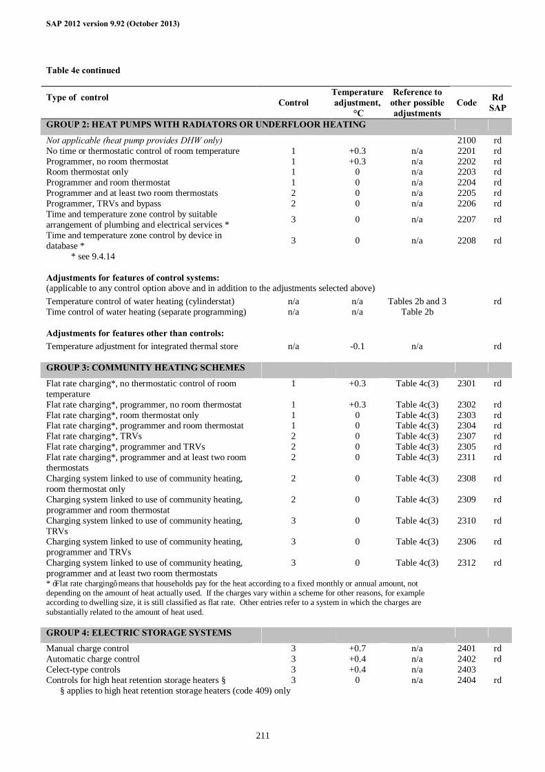
SAP 2012 version 9.92 (October 2013)
211
Table 4e continued
Type of control Control
Temperature adjustment,
°C
Reference to other possible adjustments
Code Rd SAP
GROUP 2: HEAT PUMPS WITH RADIATORS OR UNDERFLOOR HEATING
Not applicable (heat pump provides DHW only) 2100 rd No time or thermostatic control of room temperature 1 +0.3 n/a 2201 rd Programmer, no room thermostat 1 +0.3 n/a 2202 rd Room thermostat only 1 0 n/a 2203 rd Programmer and room thermostat 1 0 n/a 2204 rd Programmer and at least two room thermostats 2 0 n/a 2205 rd Programmer, TRVs and bypass 2 0 n/a 2206 rd Time and temperature zone control by suitable arrangement of plumbing and electrical services * 3 0 n/a 2207 rd
Time and temperature zone control by device in database * 3 0 n/a 2208 rd
* see 9.4.14 Adjustments for features of control systems: (applicable to any control option above and in addition to the adjustments selected above)
Temperature control of water heating (cylinderstat) n/a n/a Tables 2b and 3 rd Time control of water heating (separate programming) n/a n/a Table 2b Adjustments for features other than controls: Temperature adjustment for integrated thermal store n/a -0.1 n/a rd GROUP 3: COMMUNITY HEATING SCHEMES
Flat rate charging*, no thermostatic control of room temperature
1 +0.3 Table 4c(3) 2301 rd
Flat rate charging*, programmer, no room thermostat 1 +0.3 Table 4c(3) 2302 rd Flat rate charging*, room thermostat only 1 0 Table 4c(3) 2303 rd Flat rate charging*, programmer and room thermostat 1 0 Table 4c(3) 2304 rd Flat rate charging*, TRVs 2 0 Table 4c(3) 2307 rd Flat rate charging*, programmer and TRVs 2 0 Table 4c(3) 2305 rd Flat rate charging*, programmer and at least two room thermostats
2 0 Table 4c(3) 2311 rd
Charging system linked to use of community heating, room thermostat only
2 0 Table 4c(3) 2308 rd
Charging system linked to use of community heating, programmer and room thermostat
2 0 Table 4c(3) 2309 rd
Charging system linked to use of community heating, TRVs
3 0 Table 4c(3) 2310 rd
Charging system linked to use of community heating, programmer and TRVs
3 0 Table 4c(3) 2306 rd
Charging system linked to use of community heating, programmer and at least two room thermostats
3 0 Table 4c(3) 2312 rd
* ‘Flat rate charging’ means that households pay for the heat according to a fixed monthly or annual amount, not depending on the amount of heat actually used. If the charges vary within a scheme for other reasons, for example according to dwelling size, it is still classified as flat rate. Other entries refer to a system in which the charges are substantially related to the amount of heat used.
GROUP 4: ELECTRIC STORAGE SYSTEMS
Manual charge control 3 +0.7 n/a 2401 rd Automatic charge control 3 +0.4 n/a 2402 rd Celect-type controls 3 +0.4 n/a 2403 Controls for high heat retention storage heaters § 3 0 n/a 2404 rd § applies to high heat retention storage heaters (code 409) only
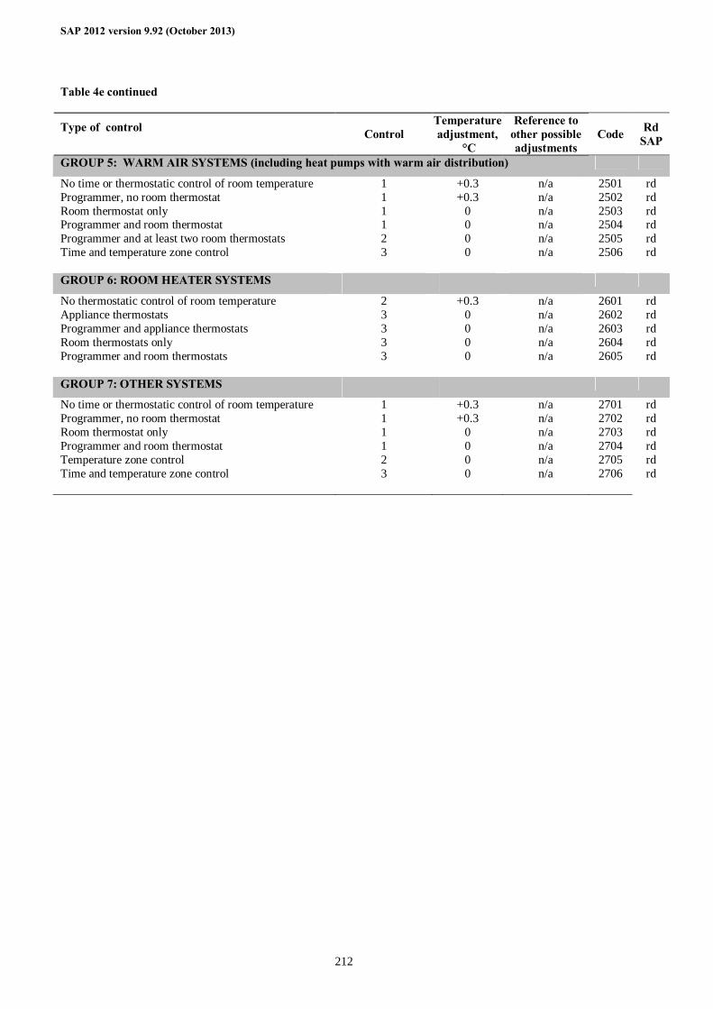
SAP 2012 version 9.92 (October 2013)
212
Table 4e continued
Type of control Control
Temperature adjustment,
°C
Reference to other possible adjustments
Code Rd SAP
GROUP 5: WARM AIR SYSTEMS (including heat pumps with warm air distribution)
No time or thermostatic control of room temperature 1 +0.3 n/a 2501 rd Programmer, no room thermostat 1 +0.3 n/a 2502 rd Room thermostat only 1 0 n/a 2503 rd Programmer and room thermostat 1 0 n/a 2504 rd Programmer and at least two room thermostats 2 0 n/a 2505 rd Time and temperature zone control 3 0 n/a 2506 rd GROUP 6: ROOM HEATER SYSTEMS
No thermostatic control of room temperature 2 +0.3 n/a 2601 rd Appliance thermostats 3 0 n/a 2602 rd Programmer and appliance thermostats 3 0 n/a 2603 rd Room thermostats only 3 0 n/a 2604 rd Programmer and room thermostats 3 0 n/a 2605 rd GROUP 7: OTHER SYSTEMS
No time or thermostatic control of room temperature 1 +0.3 n/a 2701 rd Programmer, no room thermostat 1 +0.3 n/a 2702 rd Room thermostat only 1 0 n/a 2703 rd Programmer and room thermostat 1 0 n/a 2704 rd Temperature zone control 2 0 n/a 2705 rd Time and temperature zone control 3 0 n/a 2706 rd
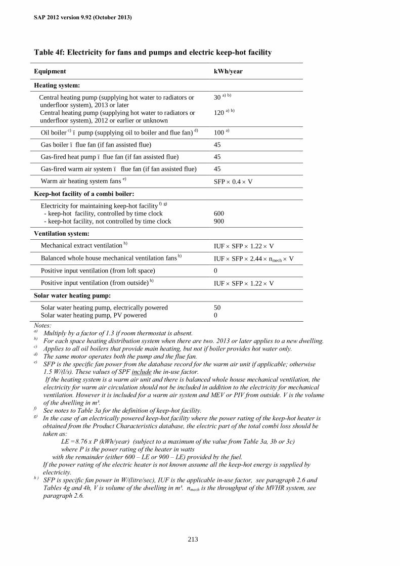
SAP 2012 version 9.92 (October 2013)
213
Table 4f: Electricity for fans and pumps and electric keep-hot facility
Equipment kWh/year
Heating system:
Central heating pump (supplying hot water to radiators or underfloor system), 2013 or later Central heating pump (supplying hot water to radiators or underfloor system), 2012 or earlier or unknown
30 a) b) 120 a) b)
Oil boiler c) – pump (supplying oil to boiler and flue fan) d) 100 a)
Gas boiler – flue fan (if fan assisted flue) 45
Gas-fired heat pump – flue fan (if fan assisted flue) 45
Gas-fired warm air system – flue fan (if fan assisted flue) 45
Warm air heating system fans e) SFP × 0.4 × V
Keep-hot facility of a combi boiler:
Electricity for maintaining keep-hot facility f) g) - keep-hot facility, controlled by time clock - keep-hot facility, not controlled by time clock
600 900
Ventilation system:
Mechanical extract ventilation h) IUF × SFP × 1.22 × V
Balanced whole house mechanical ventilation fans h) IUF × SFP × 2.44 × nmech × V
Positive input ventilation (from loft space) 0
Positive input ventilation (from outside) h) IUF × SFP × 1.22 × V
Solar water heating pump:
Solar water heating pump, electrically powered Solar water heating pump, PV powered
50 0
Notes: a) Multiply by a factor of 1.3 if room thermostat is absent. b) For each space heating distribution system when there are two. 2013 or later applies to a new dwelling. c) Applies to all oil boilers that provide main heating, but not if boiler provides hot water only. d) The same motor operates both the pump and the flue fan. e) SFP is the specific fan power from the database record for the warm air unit if applicable; otherwise
1.5 W/(l/s). These values of SPF include the in-use factor. If the heating system is a warm air unit and there is balanced whole house mechanical ventilation, the electricity for warm air circulation should not be included in addition to the electricity for mechanical ventilation. However it is included for a warm air system and MEV or PIV from outside. V is the volume of the dwelling in m³.
f) See notes to Table 3a for the definition of keep-hot facility. g) In the case of an electrically powered keep-hot facility where the power rating of the keep-hot heater is
obtained from the Product Characteristics database, the electric part of the total combi loss should be taken as:
LE =8.76 x P (kWh/year) (subject to a maximum of the value from Table 3a, 3b or 3c) where P is the power rating of the heater in watts
with the remainder (either 600 – LE or 900 – LE) provided by the fuel. If the power rating of the electric heater is not known assume all the keep-hot energy is supplied by electricity.
h ) SFP is specific fan power in W/(litre/sec), IUF is the applicable in-use factor, see paragraph 2.6 and Tables 4g and 4h, V is volume of the dwelling in m³. nmech is the throughput of the MVHR system, see paragraph 2.6.
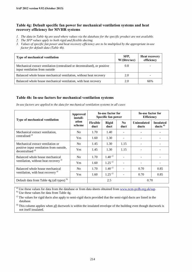
SAP 2012 version 9.92 (October 2013)
214
Table 4g: Default specific fan power for mechanical ventilation systems and heat recovery efficiency for MVHR systems
1. The data in Table 4g are used where values via the database for the specific product are not available. 2. The SFP values apply to both rigid and flexible ducting. 3. Values of specific fan power and heat recovery efficiency are to be multiplied by the appropriate in-use
factor for default data (Table 4h).
Type of mechanical ventilation SFP, W/(litre/sec)
Heat recovery efficiency
Mechanical extract ventilation (centralised or decentralised), or positive input ventilation from outside
0.8 -
Balanced whole house mechanical ventilation, without heat recovery 2.0 -
Balanced whole house mechanical ventilation, with heat recovery 2.0 66% Table 4h: In-use factors for mechanical ventilation systems
In-use factors are applied to the data for mechanical ventilation systems in all cases
In-use factor for Specific fan power
In-use factor for Efficiency
Type of mechanical ventilation
Approved install-ation
scheme Flexible
duct Rigid duct
No duct
Uninsulated ducts
Insulated ducts d)
No 1.70 1.40 - - - Mechanical extract ventilation, centralised a) Yes 1.60 1.30 - - -
No 1.45 1.30 1.15 - - Mechanical extract ventilation or positive input ventilation from outside, decentralised a) Yes 1.45 1.30 1.15 - -
No 1.70 1.40 c) - - - Balanced whole house mechanical ventilation, without heat recovery a) Yes 1.60 1.25 c) - - -
No 1.70 1.40 c) - 0.70 0.85 Balanced whole house mechanical ventilation, with heat recovery a) Yes 1.60 1.25 c) - 0.70 0.85
Default data from Table 4g (all types) b) 2.5 0.70 a) Use these values for data from the database or from data sheets obtained from www.ncm-pcdb.org.uk/sap. b) Use these values for data from Table 4g. c) The values for rigid ducts also apply to semi-rigid ducts provided that the semi-rigid ducts are listed in the
database. d) This column applies when all ductwork is within the insulated envelope of the building even though ductwork is
not itself insulated.
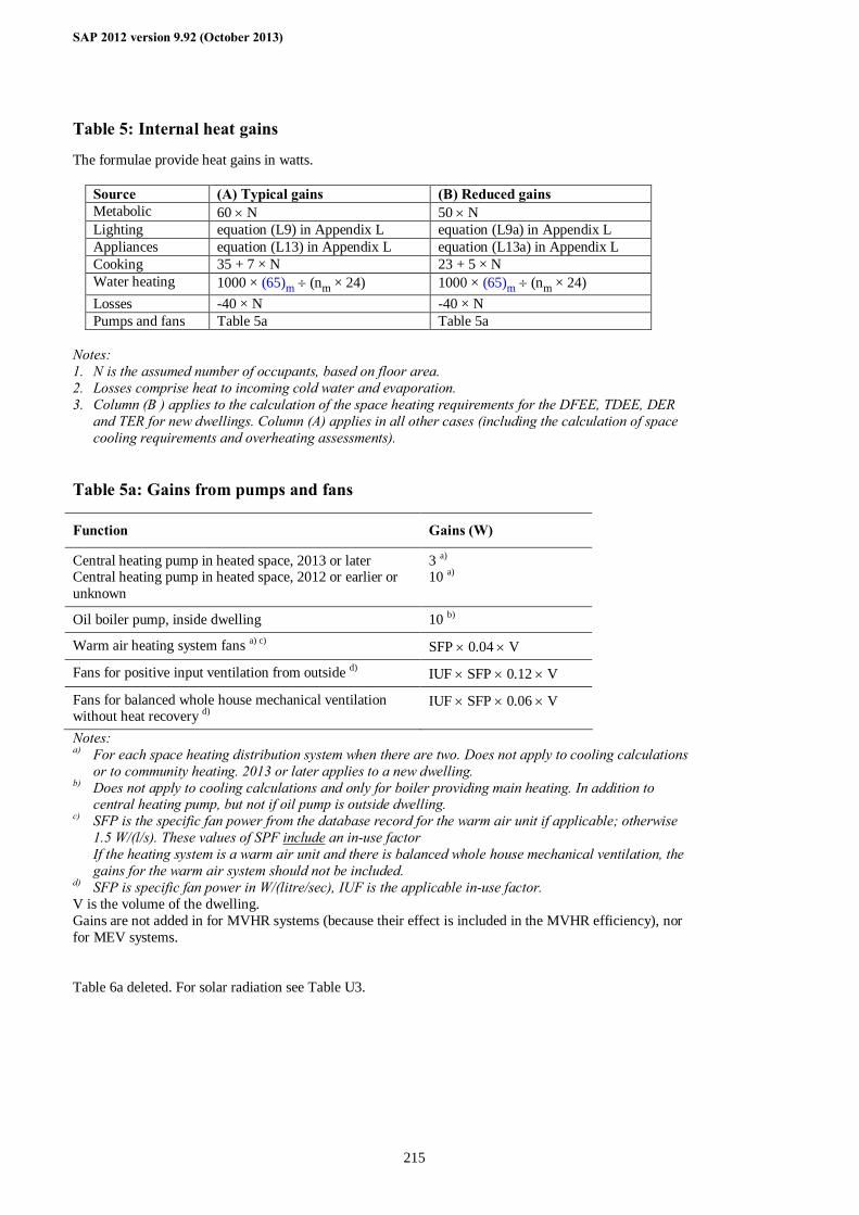
SAP 2012 version 9.92 (October 2013)
215
Table 5: Internal heat gains
The formulae provide heat gains in watts.
Source (A) Typical gains (B) Reduced gains Metabolic 60 × N 50 × N Lighting equation (L9) in Appendix L equation (L9a) in Appendix L Appliances equation (L13) in Appendix L equation (L13a) in Appendix L Cooking 35 + 7 × N 23 + 5 × N Water heating 1000 × (65)m ÷ (nm × 24) 1000 × (65)m ÷ (nm × 24) Losses -40 × N -40 × N Pumps and fans Table 5a Table 5a
Notes: 1. N is the assumed number of occupants, based on floor area. 2. Losses comprise heat to incoming cold water and evaporation. 3. Column (B ) applies to the calculation of the space heating requirements for the DFEE, TDEE, DER
and TER for new dwellings. Column (A) applies in all other cases (including the calculation of space cooling requirements and overheating assessments).
Table 5a: Gains from pumps and fans
Function Gains (W)
Central heating pump in heated space, 2013 or later Central heating pump in heated space, 2012 or earlier or unknown
3 a) 10 a)
Oil boiler pump, inside dwelling 10 b)
Warm air heating system fans a) c) SFP × 0.04 × V
Fans for positive input ventilation from outside d) IUF × SFP × 0.12 × V
Fans for balanced whole house mechanical ventilation without heat recovery d)
IUF × SFP × 0.06 × V
Notes: a) For each space heating distribution system when there are two. Does not apply to cooling calculations
or to community heating. 2013 or later applies to a new dwelling. b) Does not apply to cooling calculations and only for boiler providing main heating. In addition to
central heating pump, but not if oil pump is outside dwelling. c) SFP is the specific fan power from the database record for the warm air unit if applicable; otherwise
1.5 W/(l/s). These values of SPF include an in-use factor If the heating system is a warm air unit and there is balanced whole house mechanical ventilation, the gains for the warm air system should not be included.
d) SFP is specific fan power in W/(litre/sec), IUF is the applicable in-use factor. V is the volume of the dwelling. Gains are not added in for MVHR systems (because their effect is included in the MVHR efficiency), nor for MEV systems. Table 6a deleted. For solar radiation see Table U3.
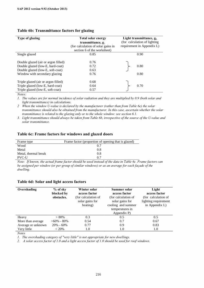
SAP 2012 version 9.92 (October 2013)
216
Table 6b: Transmittance factors for glazing
Type of glazing Total solar energy transmittance, g⊥
(for calculation of solar gains in section 6 of the worksheet)
Light transmittance, gL (for calculation of lighting requirement in Appendix L)
Single glazed 0.85 0.90 Double glazed (air or argon filled) 0.76 Double glazed (low-E, hard-coat) 0.72 Double glazed (low-E, soft-coat) 0.63
0.80
Window with secondary glazing 0.76 0.80 Triple glazed (air or argon filled) 0.68 Triple glazed (low-E, hard-coat) 0.64 Triple glazed (low-E, soft-coat) 0.57
0.70
Notes: 1. The values are for normal incidence of solar radiation and they are multiplied by 0.9 (both solar and
light transmittance) in calculations. 2 When the window U-value is declared by the manufacturer (rather than from Table 6e) the solar
transmittance should also be obtained from the manufacturer. In this case, ascertain whether the solar transmittance is related to the glazing only or to the whole window: see section 6.1.
3. Light transmittance should always be taken from Table 6b, irrespective of the source of the U-value and solar transmittance.
Table 6c: Frame factors for windows and glazed doors
Frame type Frame factor (proportion of opening that is glazed) Wood 0.7 Metal 0.8 Metal, thermal break 0.8 PVC-U 0.7 Note: If known, the actual frame factor should be used instead of the data in Table 6c. Frame factors can be assigned per window (or per group of similar windows) or as an average for each façade of the dwelling. Table 6d: Solar and light access factors
Overshading % of sky blocked by obstacles.
Winter solar access factor
(for calculation of solar gains for
heating)
Summer solar access factor
(for calculation of solar gains for
cooling and summer temperatures in
Appendix P)
Light access factor
(for calculation of lighting requirement
in Appendix L)
Heavy > 80% 0.3 0.5 0.5 More than average >60% - 80% 0.54 0.7 0.67 Average or unknown 20% - 60% 0.77 0.9 0.83 Very little < 20% 1.0 1.0 1.0 Notes 1. The overshading category of "very little" is not appropriate for new dwellings. 2. A solar access factor of 1.0 and a light access factor of 1.0 should be used for roof windows.
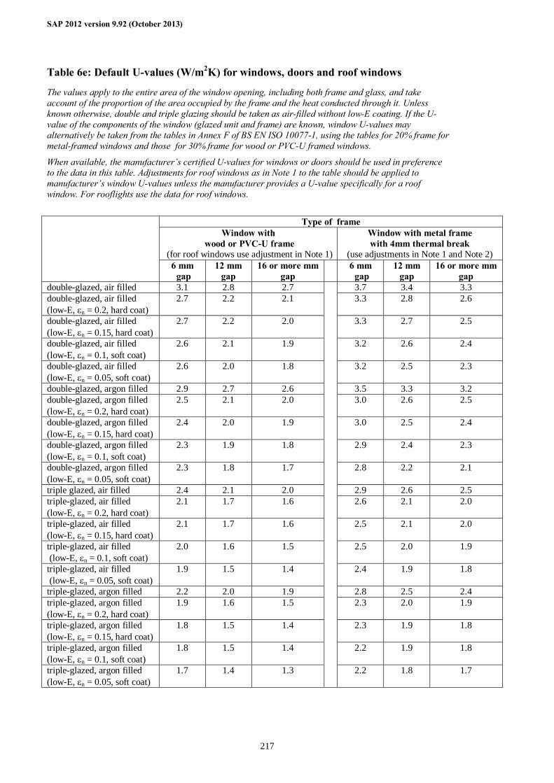
SAP 2012 version 9.92 (October 2013)
217
Table 6e: Default U-values (W/m2K) for windows, doors and roof windows
The values apply to the entire area of the window opening, including both frame and glass, and take account of the proportion of the area occupied by the frame and the heat conducted through it. Unless known otherwise, double and triple glazing should be taken as air-filled without low-E coating. If the U-value of the components of the window (glazed unit and frame) are known, window U-values may alternatively be taken from the tables in Annex F of BS EN ISO 10077-1, using the tables for 20% frame for metal-framed windows and those for 30% frame for wood or PVC-U framed windows.
When available, the manufacturer’s certified U-values for windows or doors should be used in preference to the data in this table. Adjustments for roof windows as in Note 1 to the table should be applied to manufacturer’s window U-values unless the manufacturer provides a U-value specifically for a roof window. For rooflights use the data for roof windows.
Type of frame Window with
wood or PVC-U frame (for roof windows use adjustment in Note 1)
Window with metal frame with 4mm thermal break
(use adjustments in Note 1 and Note 2) 6 mm
gap 12 mm
gap 16 or more mm
gap 6 mm
gap 12 mm
gap 16 or more mm
gap double-glazed, air filled 3.1 2.8 2.7 3.7 3.4 3.3 double-glazed, air filled (low-E, εn = 0.2, hard coat)
2.7 2.2 2.1 3.3 2.8 2.6
double-glazed, air filled (low-E, εn = 0.15, hard coat)
2.7 2.2 2.0 3.3 2.7 2.5
double-glazed, air filled (low-E, εn = 0.1, soft coat)
2.6 2.1 1.9 3.2 2.6 2.4
double-glazed, air filled (low-E, εn = 0.05, soft coat)
2.6 2.0 1.8 3.2 2.5 2.3
double-glazed, argon filled 2.9 2.7 2.6 3.5 3.3 3.2 double-glazed, argon filled (low-E, εn = 0.2, hard coat)
2.5 2.1 2.0 3.0 2.6 2.5
double-glazed, argon filled (low-E, εn = 0.15, hard coat)
2.4 2.0 1.9 3.0 2.5 2.4
double-glazed, argon filled (low-E, εn = 0.1, soft coat)
2.3 1.9 1.8 2.9 2.4 2.3
double-glazed, argon filled (low-E, εn = 0.05, soft coat)
2.3 1.8 1.7 2.8 2.2 2.1
triple glazed, air filled 2.4 2.1 2.0 2.9 2.6 2.5 triple-glazed, air filled (low-E, εn = 0.2, hard coat)
2.1 1.7 1.6 2.6 2.1 2.0
triple-glazed, air filled (low-E, εn = 0.15, hard coat)
2.1 1.7 1.6 2.5 2.1 2.0
triple-glazed, air filled (low-E, εn = 0.1, soft coat)
2.0 1.6 1.5 2.5 2.0 1.9
triple-glazed, air filled (low-E, εn = 0.05, soft coat)
1.9 1.5 1.4 2.4 1.9 1.8
triple-glazed, argon filled 2.2 2.0 1.9 2.8 2.5 2.4 triple-glazed, argon filled (low-E, εn = 0.2, hard coat)
1.9 1.6 1.5 2.3 2.0 1.9
triple-glazed, argon filled (low-E, εn = 0.15, hard coat)
1.8 1.5 1.4 2.3 1.9 1.8
triple-glazed, argon filled (low-E, εn = 0.1, soft coat)
1.8 1.5 1.4 2.2 1.9 1.8
triple-glazed, argon filled (low-E, εn = 0.05, soft coat)
1.7 1.4 1.3
2.2 1.8 1.7
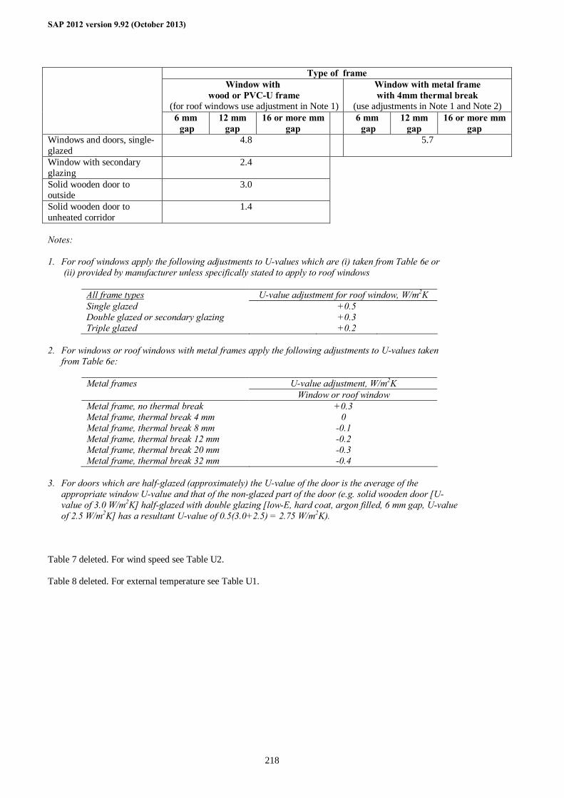
SAP 2012 version 9.92 (October 2013)
218
Type of frame Window with
wood or PVC-U frame (for roof windows use adjustment in Note 1)
Window with metal frame with 4mm thermal break
(use adjustments in Note 1 and Note 2) 6 mm
gap 12 mm
gap 16 or more mm
gap 6 mm
gap 12 mm
gap 16 or more mm
gap Windows and doors, single-glazed
4.8 5.7
Window with secondary glazing
2.4
Solid wooden door to outside
3.0
Solid wooden door to unheated corridor
1.4
Notes: 1. For roof windows apply the following adjustments to U-values which are (i) taken from Table 6e or
(ii) provided by manufacturer unless specifically stated to apply to roof windows
All frame types U-value adjustment for roof window, W/m2K Single glazed +0.5 Double glazed or secondary glazing +0.3 Triple glazed +0.2
2. For windows or roof windows with metal frames apply the following adjustments to U-values taken
from Table 6e:
Metal frames U-value adjustment, W/m2K Window or roof window Metal frame, no thermal break +0.3 Metal frame, thermal break 4 mm 0 Metal frame, thermal break 8 mm -0.1 Metal frame, thermal break 12 mm -0.2 Metal frame, thermal break 20 mm -0.3 Metal frame, thermal break 32 mm -0.4
3. For doors which are half-glazed (approximately) the U-value of the door is the average of the
appropriate window U-value and that of the non-glazed part of the door (e.g. solid wooden door [U-value of 3.0 W/m2K] half-glazed with double glazing [low-E, hard coat, argon filled, 6 mm gap, U-value of 2.5 W/m2K] has a resultant U-value of 0.5(3.0+2.5) = 2.75 W/m2K).
Table 7 deleted. For wind speed see Table U2. Table 8 deleted. For external temperature see Table U1.
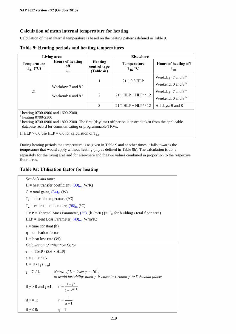
SAP 2012 version 9.92 (October 2013)
219
Calculation of mean internal temperature for heating Calculation of mean internal temperature is based on the heating patterns defined in Table 9. Table 9: Heating periods and heating temperatures
Living area Elsewhere
Temperature Th1 (°C)
Hours of heating off toff
Heating control type (Table 4e)
Temperature Th2 °C
Hours of heating off toff
1 21 – 0.5 HLP Weekday: 7 and 8 a
Weekend: 0 and 8 b
2 21 – HLP + HLP² / 12 Weekday: 7 and 8 a
Weekend: 0 and 8 b
21 Weekday: 7 and 8 a Weekend: 0 and 8 b
3 21 – HLP + HLP² / 12 All days: 9 and 8 c a heating 0700-0900 and 1600-2300 b heating 0700-2300 c heating 0700-0900 and 1800-2300. The first (daytime) off period is instead taken from the applicable database record for communicating or programmable TRVs.
If HLP > 6.0 use HLP = 6.0 for calculation of Th2
During heating periods the temperature is as given in Table 9 and at other times it falls towards the temperature that would apply without heating (Tsc as defined in Table 9b). The calculation is done separately for the living area and for elsewhere and the two values combined in proportion to the respective floor areas. Table 9a: Utilisation factor for heating
Symbols and units H = heat transfer coefficient, (39)m (W/K)
G = total gains, (84)m (W)
Ti = internal temperature (°C)
Te = external temperature, (96)m (°C)
TMP = Thermal Mass Parameter, (35), (kJ/m²K) (= Cm for building / total floor area) HLP = Heat Loss Parameter, (40)m (W/m²K)
τ = time constant (h) η = utilisation factor L = heat loss rate (W) Calculation of utilisation factor τ = TMP / (3.6 × HLP) a = 1 + τ / 15 L = H (Ti – Te)
γ = G / L Notes: if L = 0 set γ = 106 ; to avoid instability when γ is close to 1 round γ to 8 decimal places
if γ > 0 and γ ≠1: 1a
a
11
+γ−
γ−=η
if γ = 1: 1a
a+
=η
if γ ≤ 0: η = 1
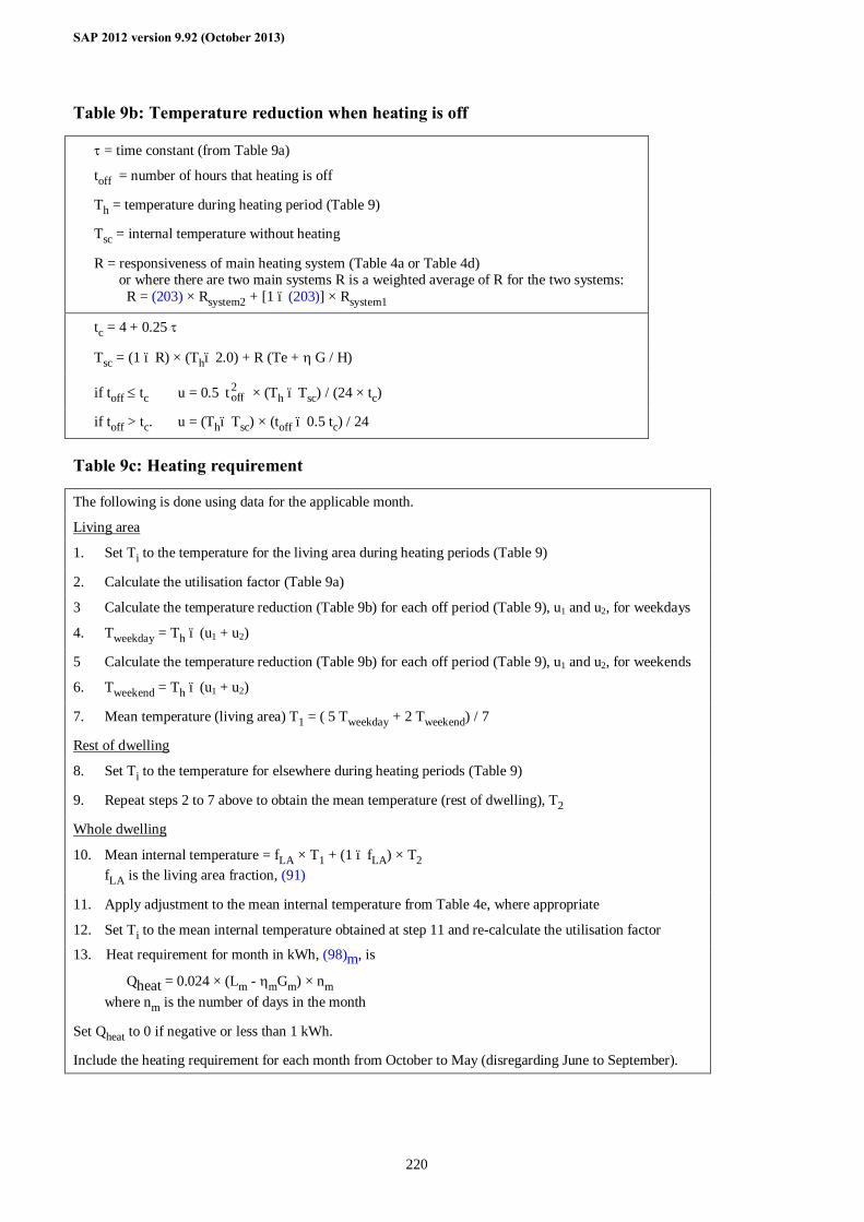
SAP 2012 version 9.92 (October 2013)
220
Table 9b: Temperature reduction when heating is off
τ = time constant (from Table 9a)
toff = number of hours that heating is off
Th = temperature during heating period (Table 9)
Tsc = internal temperature without heating
R = responsiveness of main heating system (Table 4a or Table 4d) or where there are two main systems R is a weighted average of R for the two systems: R = (203) × Rsystem2 + [1 – (203)] × Rsystem1
tc = 4 + 0.25 τ
Tsc = (1 – R) × (Th– 2.0) + R (Te + η G / H)
if toff ≤ tc u = 0.5 2offt × (Th – Tsc) / (24 × tc)
if toff > tc. u = (Th– Tsc) × (toff – 0.5 tc) / 24
Table 9c: Heating requirement
The following is done using data for the applicable month.
Living area
1. Set Ti to the temperature for the living area during heating periods (Table 9)
2. Calculate the utilisation factor (Table 9a)
3 Calculate the temperature reduction (Table 9b) for each off period (Table 9), u1 and u2, for weekdays
4. Tweekday = Th – (u1 + u2)
5 Calculate the temperature reduction (Table 9b) for each off period (Table 9), u1 and u2, for weekends
6. Tweekend = Th – (u1 + u2)
7. Mean temperature (living area) T1 = ( 5 Tweekday + 2 Tweekend) / 7
Rest of dwelling
8. Set Ti to the temperature for elsewhere during heating periods (Table 9)
9. Repeat steps 2 to 7 above to obtain the mean temperature (rest of dwelling), T2
Whole dwelling
10. Mean internal temperature = fLA × T1 + (1 – fLA) × T2 fLA is the living area fraction, (91)
11. Apply adjustment to the mean internal temperature from Table 4e, where appropriate
12. Set Ti to the mean internal temperature obtained at step 11 and re-calculate the utilisation factor
13. Heat requirement for month in kWh, (98)m, is
Qheat = 0.024 × (Lm - ηmGm) × nm where nm is the number of days in the month
Set Qheat to 0 if negative or less than 1 kWh.
Include the heating requirement for each month from October to May (disregarding June to September).
SAP 2012 version 9.92 (October 2013)
221
When there are two main heating systems the procedure is adapted as follows, depending on whether both systems serve the whole house or each system serves different parts. 1. Both systems heat whole house
When both systems heat all the house (or at least all those rooms with heat emitters connected to the systems), the fraction of main heat from main system 2, worksheet (203), is provided as part of the specification of the systems. Main system 1 is that which provides the greatest amount of heat. The heating controls for both systems must be compatible (same control type), and the control type concerned is used in Table 9 for the calculation of MIT in the rest of dwelling, worksheet (89)m and (90)m, and for the calculation of MIT for the whole dwelling, worksheet (93)m. 2. The two systems heat different parts of the house
When the systems heat different parts of the house they are treated as being separate. The fraction of main heat from main system 2, worksheet (203), is in the absence of specific information the fraction of the total floor area heated by main system 2. Main system 1 is that which provides heat to the living area, and heating controls for each system are specified according to those fitted to each system (and so can be different).
Calculate the mean internal temperature (MIT) for the living area according to Tables 9, 9a, 9b and 9c or, in the case of a system assessed via Appendix N, using equation (N5). This is the same as if there were only one main system except for a weighted responsiveness.
If the fraction of the dwelling heated by main system 2, (203), is greater than the rest of house area, 1 - (91), calculate the MIT for the rest of the dwelling for the heating control specified for main system 2. Otherwise calculate the MIT for the rest of the dwelling twice, once for the heating control specified for main system 1 and once for the heating control specified for main system 2; this includes a different heating duration, where applicable, for systems assessed via Appendix N. Obtain the average of these two temperatures with weighting factors (203) / [1 - (91)] for the temperature calculated for the controls on main system 2; [1 - (203) - (91)] / [1 - (91)] for the temperature calculated for the controls on main system 1; and use that average as T2 for the calculation of worksheet (92)m. This step can be omitted if the heating control type (1, 2 or 3 from Table 4e) is the same for both systems. In the calculation of MIT for the whole dwelling, worksheet (93)m, use the temperature adjustment from Table 4e for the heating controls on each main system, weighted by the fraction of the dwelling heated by each system, i.e. by (1 – (203)) for system 1 and (203) for system 2.
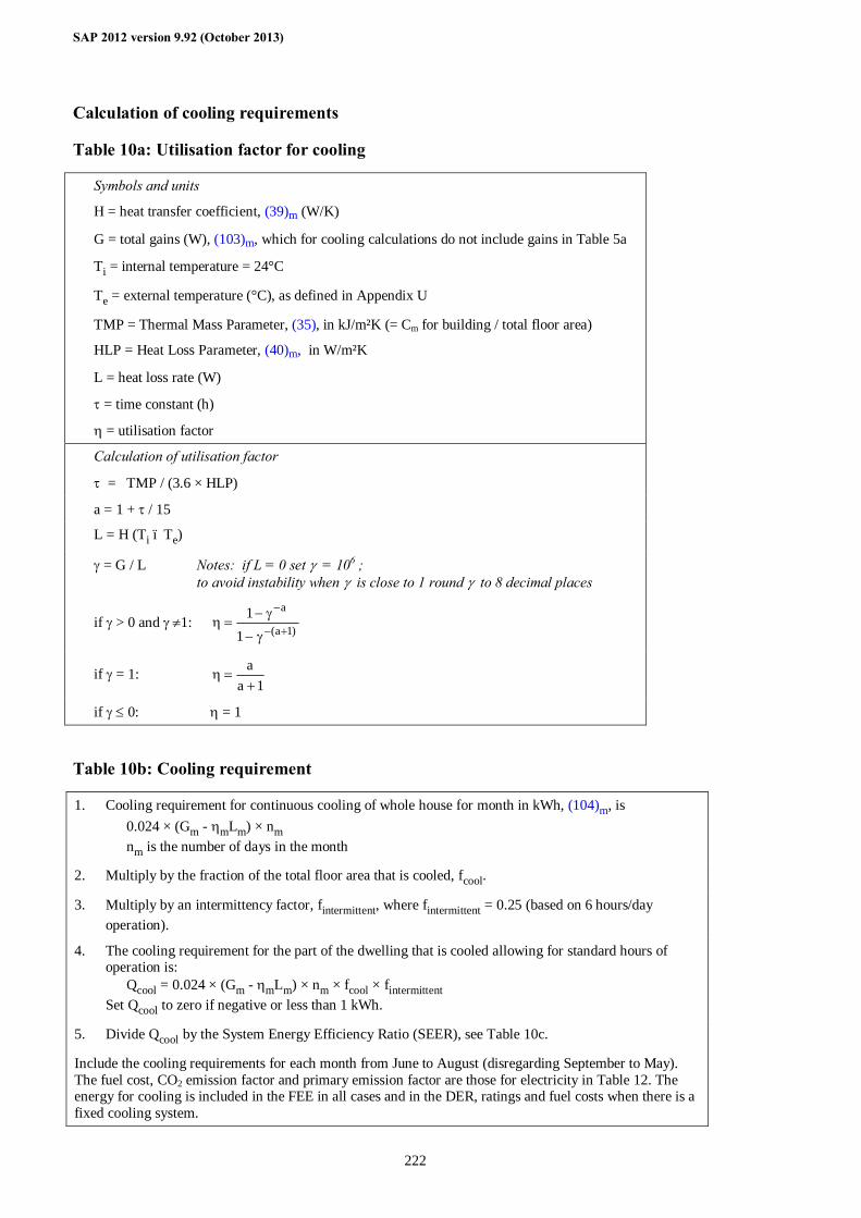
SAP 2012 version 9.92 (October 2013)
222
Calculation of cooling requirements
Table 10a: Utilisation factor for cooling
Symbols and units
H = heat transfer coefficient, (39)m (W/K)
G = total gains (W), (103)m, which for cooling calculations do not include gains in Table 5a
Ti = internal temperature = 24°C
Te = external temperature (°C), as defined in Appendix U
TMP = Thermal Mass Parameter, (35), in kJ/m²K (= Cm for building / total floor area)
HLP = Heat Loss Parameter, (40)m, in W/m²K
L = heat loss rate (W)
τ = time constant (h)
η = utilisation factor
Calculation of utilisation factor
τ = TMP / (3.6 × HLP)
a = 1 + τ / 15
L = H (Ti – Te)
γ = G / L Notes: if L = 0 set γ = 106 ; to avoid instability when γ is close to 1 round γ to 8 decimal places
if γ > 0 and γ ≠1: )1a(
a
11
+−
−
γ−
γ−=η
if γ = 1: 1a
a+
=η
if γ ≤ 0: η = 1 Table 10b: Cooling requirement
1. Cooling requirement for continuous cooling of whole house for month in kWh, (104)m, is 0.024 × (Gm - ηmLm) × nm nm is the number of days in the month
2. Multiply by the fraction of the total floor area that is cooled, fcool.
3. Multiply by an intermittency factor, fintermittent, where fintermittent = 0.25 (based on 6 hours/day operation).
4. The cooling requirement for the part of the dwelling that is cooled allowing for standard hours of operation is: Qcool = 0.024 × (Gm - ηmLm) × nm × fcool × fintermittent Set Qcool to zero if negative or less than 1 kWh.
5. Divide Qcool by the System Energy Efficiency Ratio (SEER), see Table 10c.
Include the cooling requirements for each month from June to August (disregarding September to May). The fuel cost, CO2 emission factor and primary emission factor are those for electricity in Table 12. The energy for cooling is included in the FEE in all cases and in the DER, ratings and fuel costs when there is a fixed cooling system.
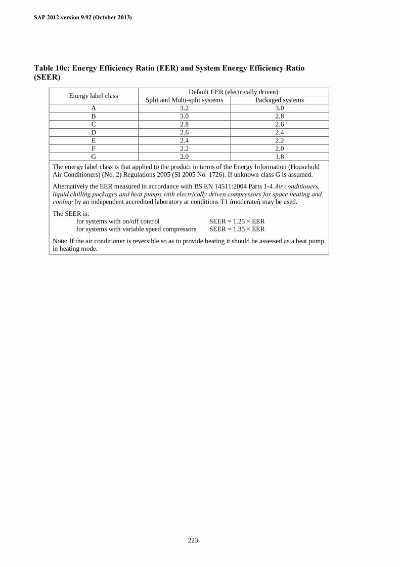
SAP 2012 version 9.92 (October 2013)
223
Table 10c: Energy Efficiency Ratio (EER) and System Energy Efficiency Ratio (SEER)
Default EER (electrically driven) Energy label class Split and Multi-split systems Packaged systems A 3.2 3.0 B 3.0 2.8 C 2.8 2.6 D 2.6 2.4 E 2.4 2.2 F 2.2 2.0 G 2.0 1.8
The energy label class is that applied to the product in terms of the Energy Information (Household Air Conditioners) (No. 2) Regulations 2005 (SI 2005 No. 1726). If unknown class G is assumed.
Alternatively the EER measured in accordance with BS EN 14511:2004 Parts 1-4 Air conditioners, liquid chilling packages and heat pumps with electrically driven compressors for space heating and cooling by an independent accredited laboratory at conditions T1 ‘moderate’, may be used.
The SEER is: for systems with on/off control SEER = 1.25 × EER for systems with variable speed compressors SEER = 1.35 × EER
Note: If the air conditioner is reversible so as to provide heating it should be assessed as a heat pump in heating mode.

SAP 2012 version 9.92 (October 2013)
224
Table 11: Fraction of heat supplied by secondary heating systems
Main heating system Secondary system Fraction from secondary
All gas, oil and solid fuel systems all secondary systems 0.10
Micro-cogeneration all secondary systems see Appendix N
Heat pump, data from database
Heat pump, data from Table 4a
all secondary systems
all secondary systems
see Appendix N
0.10
Electric storage heaters (not integrated) - not fan-assisted - fan-assisted - high heat retention (as defined in 9.2.8)
Integrated storage/direct-acting electric systems
Electric CPSU
Electric room heaters
Other electric systems
all secondary systems
all secondary systems
all secondary systems
all secondary systems
all secondary systems
0.15 0.10 0.10
0.10
0.10
0.20
0.10
Community heating all secondary systems 0.10
Notes: 1. See also Appendix A. 2. If an off-peak tariff is present, see Table 12a for proportions at the high and low rates 3. If there are two main systems, ‘main heating system’ is that heating the living area
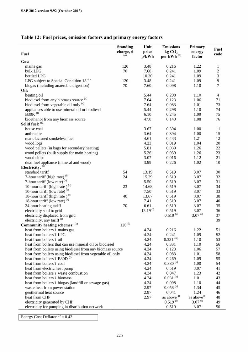
SAP 2012 version 9.92 (October 2013)
225
Table 12: Fuel prices, emission factors and primary energy factors
Fuel
Standing charge, £
(a)
Unit price
p/kWh
Emissions kg CO2
per kWh (b)
Primary energy factor
Fuel code
Gas: mains gas 120 3.48 0.216 1.22 1 bulk LPG 70 7.60 0.241 1.09 2 bottled LPG 10.30 0.241 1.09 3 LPG subject to Special Condition 18 (c) 120 3.48 0.241 1.09 9 biogas (including anaerobic digestion) 70 7.60 0.098 1.10 7 Oil: heating oil 5.44 0.298 1.10 4 biodiesel from any biomass source (d) 7.64 0.123 1.06 71 biodiesel from vegetable oil only (e) 7.64 0.083 1.01 73 appliances able to use mineral oil or biodiesel 5.44 0.298 1.10 74 B30K (f) 6.10 0.245 1.09 75 bioethanol from any biomass source 47.0 0.140 1.08 76 Solid fuel: (g) house coal 3.67 0.394 1.00 11 anthracite 3.64 0.394 1.00 15 manufactured smokeless fuel 4.61 0.433 1.21 12 wood logs 4.23 0.019 1.04 20 wood pellets (in bags for secondary heating) 5.81 0.039 1.26 22 wood pellets (bulk supply for main heating) 5.26 0.039 1.26 23 wood chips 3.07 0.016 1.12 21 dual fuel appliance (mineral and wood) 3.99 0.226 1.02 10 Electricity: (a) standard tariff 54 13.19 0.519 3.07 30 7-hour tariff (high rate) (h) 24 15.29 0.519 3.07 32 7-hour tariff (low rate) (h) 5.50 0.519 3.07 31 10-hour tariff (high rate ) (h) 23 14.68 0.519 3.07 34 10-hour tariff (low rate) (h) 7.50 0.519 3.07 33 18-hour tariff (high rate ) (h) 40 13.67 0.519 3.07 38 18-hour tariff (low rate) (h) 7.41 0.519 3.07 40 24-hour heating tariff 70 6.61 0.519 3.07 35 electricity sold to grid 13.19 (i) 0.519 3.07 36 electricity displaced from grid 0.519 (i) 3.07 (i) 37 electricity, any tariff (j) 39 Community heating schemes: (k) 120 (l) heat from boilers – mains gas 4.24 0.216 1.22 51 heat from boilers – LPG 4.24 0.241 1.09 52 heat from boilers – oil 4.24 0.331 (m) 1.10 53 heat from boilers that can use mineral oil or biodiesel 4.24 0.331 1.10 56 heat from boilers using biodiesel from any biomass source 4.24 0.123 1.06 57 heat from boilers using biodiesel from vegetable oil only 4.24 0.083 1.01 58 heat from boilers – B30D (f) 4.24 0.269 1.09 55 heat from boilers – coal 4.24 0.380 (n) 1.00 54 heat from electric heat pump 4.24 0.519 3.07 41 heat from boilers – waste combustion 4.24 0.047 1.23 42 heat from boilers – biomass 4.24 0.031 (o) 1.01 43 heat from boilers – biogas (landfill or sewage gas) 4.24 0.098 1.10 44 waste heat from power station 2.97 0.058 (p) 1.34 45 geothermal heat source 2.97 0.041 1.24 46 heat from CHP 2.97 as above(q) as above(q) 48 electricity generated by CHP 0.519 (i) 3.07 (i) 49 electricity for pumping in distribution network 0.519 3.07 50 Energy Cost Deflator (r) = 0.42
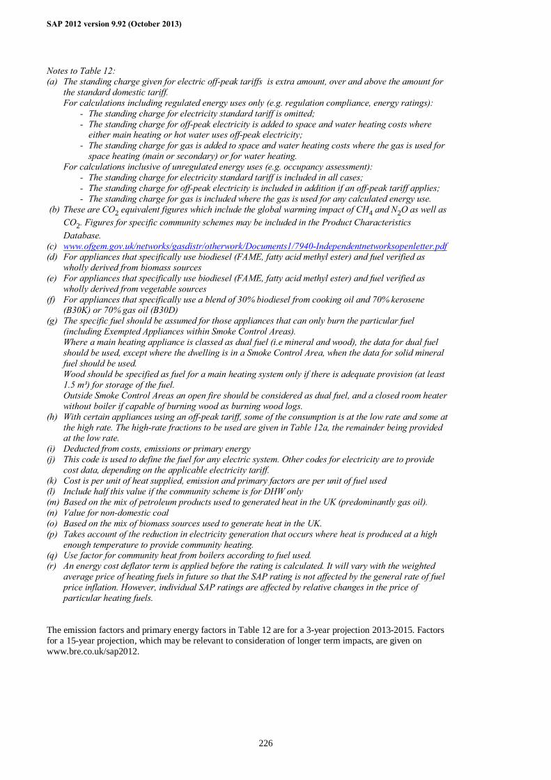
SAP 2012 version 9.92 (October 2013)
226
Notes to Table 12: (a) The standing charge given for electric off-peak tariffs is extra amount, over and above the amount for
the standard domestic tariff. For calculations including regulated energy uses only (e.g. regulation compliance, energy ratings):
- The standing charge for electricity standard tariff is omitted; - The standing charge for off-peak electricity is added to space and water heating costs where
either main heating or hot water uses off-peak electricity; - The standing charge for gas is added to space and water heating costs where the gas is used for
space heating (main or secondary) or for water heating. For calculations inclusive of unregulated energy uses (e.g. occupancy assessment):
- The standing charge for electricity standard tariff is included in all cases; - The standing charge for off-peak electricity is included in addition if an off-peak tariff applies; - The standing charge for gas is included where the gas is used for any calculated energy use.
(b) These are CO2 equivalent figures which include the global warming impact of CH4 and N2O as well as CO2. Figures for specific community schemes may be included in the Product Characteristics Database.
(c) www.ofgem.gov.uk/networks/gasdistr/otherwork/Documents1/7940-Independentnetworksopenletter.pdf (d) For appliances that specifically use biodiesel (FAME, fatty acid methyl ester) and fuel verified as
wholly derived from biomass sources (e) For appliances that specifically use biodiesel (FAME, fatty acid methyl ester) and fuel verified as
wholly derived from vegetable sources (f) For appliances that specifically use a blend of 30% biodiesel from cooking oil and 70% kerosene
(B30K) or 70% gas oil (B30D) (g) The specific fuel should be assumed for those appliances that can only burn the particular fuel
(including Exempted Appliances within Smoke Control Areas). Where a main heating appliance is classed as dual fuel (i.e mineral and wood), the data for dual fuel should be used, except where the dwelling is in a Smoke Control Area, when the data for solid mineral fuel should be used. Wood should be specified as fuel for a main heating system only if there is adequate provision (at least 1.5 m³) for storage of the fuel. Outside Smoke Control Areas an open fire should be considered as dual fuel, and a closed room heater without boiler if capable of burning wood as burning wood logs.
(h) With certain appliances using an off-peak tariff, some of the consumption is at the low rate and some at the high rate. The high-rate fractions to be used are given in Table 12a, the remainder being provided at the low rate.
(i) Deducted from costs, emissions or primary energy (j) This code is used to define the fuel for any electric system. Other codes for electricity are to provide
cost data, depending on the applicable electricity tariff. (k) Cost is per unit of heat supplied, emission and primary factors are per unit of fuel used (l) Include half this value if the community scheme is for DHW only (m) Based on the mix of petroleum products used to generated heat in the UK (predominantly gas oil). (n) Value for non-domestic coal (o) Based on the mix of biomass sources used to generate heat in the UK. (p) Takes account of the reduction in electricity generation that occurs where heat is produced at a high
enough temperature to provide community heating. (q) Use factor for community heat from boilers according to fuel used. (r) An energy cost deflator term is applied before the rating is calculated. It will vary with the weighted
average price of heating fuels in future so that the SAP rating is not affected by the general rate of fuel price inflation. However, individual SAP ratings are affected by relative changes in the price of particular heating fuels.
The emission factors and primary energy factors in Table 12 are for a 3-year projection 2013-2015. Factors for a 15-year projection, which may be relevant to consideration of longer term impacts, are given on www.bre.co.uk/sap2012.
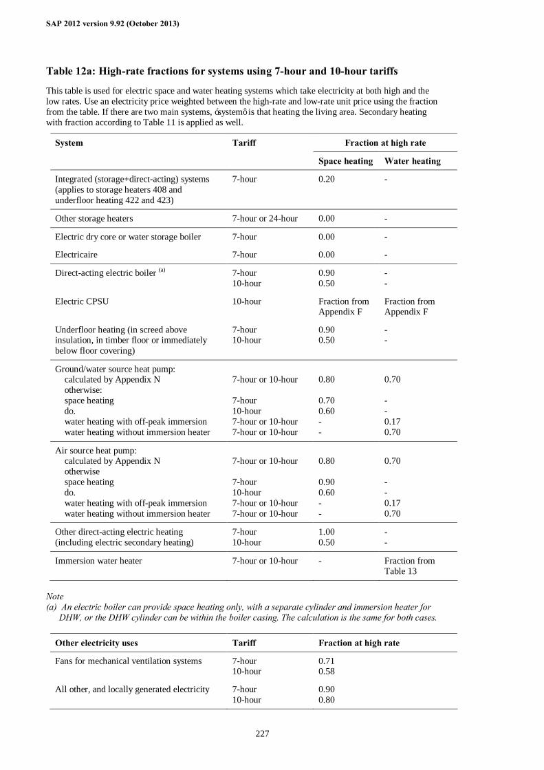
SAP 2012 version 9.92 (October 2013)
227
Table 12a: High-rate fractions for systems using 7-hour and 10-hour tariffs
This table is used for electric space and water heating systems which take electricity at both high and the low rates. Use an electricity price weighted between the high-rate and low-rate unit price using the fraction from the table. If there are two main systems, ‘system’ is that heating the living area. Secondary heating with fraction according to Table 11 is applied as well.
Fraction at high rate System Tariff
Space heating Water heating
Integrated (storage+direct-acting) systems (applies to storage heaters 408 and underfloor heating 422 and 423)
7-hour 0.20 -
Other storage heaters 7-hour or 24-hour 0.00 -
Electric dry core or water storage boiler
Electricaire
7-hour
7-hour
0.00
0.00
-
-
Direct-acting electric boiler (a)
Electric CPSU
Underfloor heating (in screed above insulation, in timber floor or immediately below floor covering)
7-hour 10-hour
10-hour
7-hour 10-hour
0.90 0.50
Fraction from Appendix F
0.90 0.50
- -
Fraction from Appendix F
- -
Ground/water source heat pump: calculated by Appendix N otherwise: space heating do. water heating with off-peak immersion water heating without immersion heater
7-hour or 10-hour 7-hour 10-hour 7-hour or 10-hour 7-hour or 10-hour
0.80 0.70 0.60 - -
0.70 - - 0.17 0.70
Air source heat pump: calculated by Appendix N otherwise space heating do. water heating with off-peak immersion water heating without immersion heater
7-hour or 10-hour 7-hour 10-hour 7-hour or 10-hour 7-hour or 10-hour
0.80 0.90 0.60 - -
0.70 - - 0.17 0.70
Other direct-acting electric heating (including electric secondary heating)
7-hour 10-hour
1.00 0.50
- -
Immersion water heater 7-hour or 10-hour - Fraction from Table 13
Note (a) An electric boiler can provide space heating only, with a separate cylinder and immersion heater for
DHW, or the DHW cylinder can be within the boiler casing. The calculation is the same for both cases.
Other electricity uses Tariff Fraction at high rate
Fans for mechanical ventilation systems 7-hour 10-hour
0.71 0.58
All other, and locally generated electricity 7-hour 10-hour
0.90 0.80
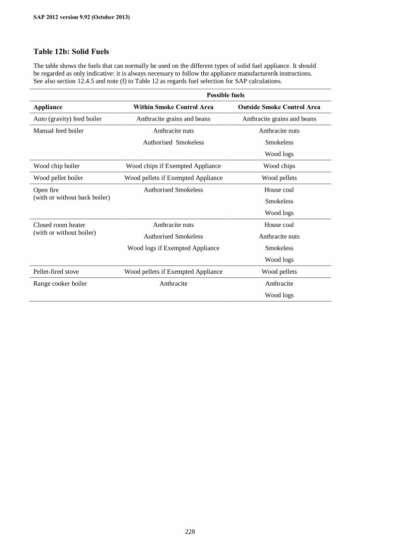
SAP 2012 version 9.92 (October 2013)
228
Table 12b: Solid Fuels
The table shows the fuels that can normally be used on the different types of solid fuel appliance. It should be regarded as only indicative: it is always necessary to follow the appliance manufacturer’s instructions. See also section 12.4.5 and note (f) to Table 12 as regards fuel selection for SAP calculations.
Possible fuels
Appliance Within Smoke Control Area Outside Smoke Control Area
Auto (gravity) feed boiler Anthracite grains and beans Anthracite grains and beans
Manual feed boiler Anthracite nuts
Authorised Smokeless
Anthracite nuts
Smokeless
Wood logs
Wood chip boiler Wood chips if Exempted Appliance Wood chips
Wood pellet boiler Wood pellets if Exempted Appliance Wood pellets
Open fire (with or without back boiler)
Authorised Smokeless House coal
Smokeless
Wood logs
Closed room heater (with or without boiler)
Anthracite nuts
Authorised Smokeless
Wood logs if Exempted Appliance
House coal
Anthracite nuts
Smokeless
Wood logs
Pellet-fired stove Wood pellets if Exempted Appliance Wood pellets
Range cooker boiler Anthracite Anthracite
Wood logs
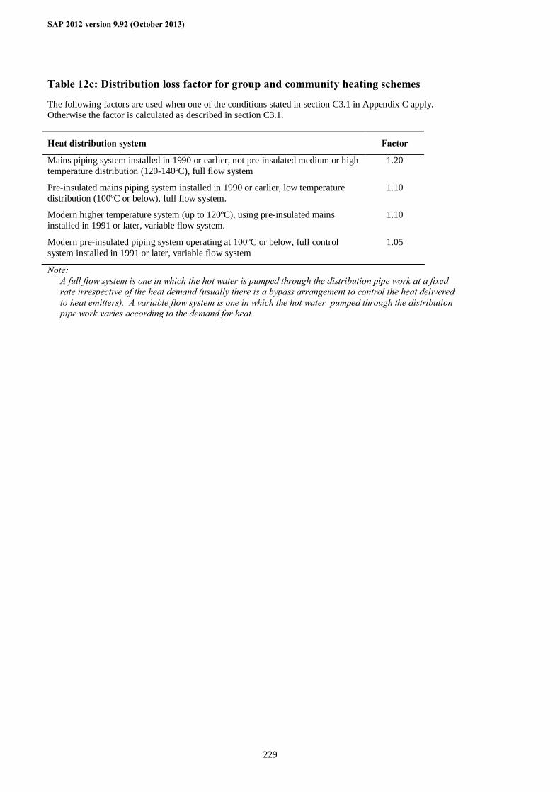
SAP 2012 version 9.92 (October 2013)
229
Table 12c: Distribution loss factor for group and community heating schemes
The following factors are used when one of the conditions stated in section C3.1 in Appendix C apply. Otherwise the factor is calculated as described in section C3.1.
Heat distribution system Factor
Mains piping system installed in 1990 or earlier, not pre-insulated medium or high temperature distribution (120-140ºC), full flow system
1.20
Pre-insulated mains piping system installed in 1990 or earlier, low temperature distribution (100ºC or below), full flow system.
1.10
Modern higher temperature system (up to 120ºC), using pre-insulated mains installed in 1991 or later, variable flow system.
1.10
Modern pre-insulated piping system operating at 100ºC or below, full control system installed in 1991 or later, variable flow system
1.05
Note: A full flow system is one in which the hot water is pumped through the distribution pipe work at a fixed
rate irrespective of the heat demand (usually there is a bypass arrangement to control the heat delivered to heat emitters). A variable flow system is one in which the hot water pumped through the distribution pipe work varies according to the demand for heat.
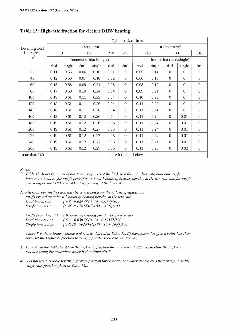
SAP 2012 version 9.92 (October 2013)
230
Table 13: High-rate fraction for electric DHW heating
Cylinder size, litres 7-hour tariff 10-hour tariff
110 160 210 245 110 160 210 Immersion (dual/single) Immersion (dual/single)
Dwelling total floor area,
m2
dual single dual single dual dual dual single dual single dual
20 0.11 0.55 0.06 0.16 0.01 0 0.05 0.14 0 0 0 40 0.12 0.56 0.07 0.18 0.02 0 0.06 0.16 0 0 0 60 0.15 0.58 0.09 0.21 0.03 0 0.08 0.19 0 0 0 80 0.17 0.60 0.10 0.24 0.04 0 0.09 0.21 0 0 0
100 0.18 0.61 0.11 0.25 0.04 0 0.10 0.23 0 0 0 120 0.18 0.61 0.11 0.26 0.04 0 0.11 0.23 0 0 0 140 0.18 0.61 0.11 0.26 0.04 0 0.11 0.24 0 0 0 160 0.19 0.61 0.12 0.26 0.04 0 0.11 0.24 0 0.01 0 180 0.19 0.61 0.12 0.26 0.05 0 0.11 0.24 0 0.01 0 200 0.19 0.61 0.12 0.27 0.05 0 0.11 0.24 0 0.01 0 220 0.19 0.61 0.12 0.27 0.05 0 0.11 0.24 0 0.01 0 240 0.19 0.61 0.12 0.27 0.05 0 0.11 0.24 0 0.01 0 260 0.19 0.62 0.12 0.27 0.05 0 0.11 0.25 0 0.02 0
more than 260 use formulae below Notes: 1) Table 13 shows fractions of electricity required at the high rate for cylinders with dual and single
immersion heaters, for tariffs providing at least 7 hours of heating per day at the low rate and for tariffs providing at least 10 hours of heating per day at the low rate.
2) Alternatively, the fraction may be calculated from the following equations: tariffs providing at least 7 hours of heating per day at the low rate Dual immersion: [(6.8 - 0.024V)N + 14 - 0.07V]/100 Single immersion: [(14530 - 762N)/V - 80 + 10N]/100 tariffs providing at least 10 hours of heating per day at the low rate Dual immersion: [(6.8 - 0.036V)N + 14 - 0.105V]/100 Single immersion: [(14530 - 762N)/(1.5V) - 80 + 10N]/100 where V is the cylinder volume and N is as defined in Table 1b. (If these formulae give a value less than
zero, set the high-rate fraction to zero; if greater than one, set to one.) 3) Do not use this table to obtain the high-rate fraction for an electric CPSU. Calculate the high-rate
fraction using the procedure described in Appendix F. 4) Do not use this table for the high-rate fraction for domestic hot water heated by a heat pump. Use the
high-rate fraction given in Table 12a.
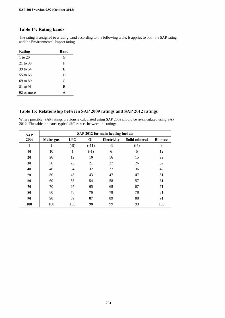
SAP 2012 version 9.92 (October 2013)
231
Table 14: Rating bands
The rating is assigned to a rating band according to the following table. It applies to both the SAP rating and the Environmental Impact rating. Rating Band 1 to 20 G 21 to 38 F 39 to 54 E 55 to 68 D 69 to 80 C 81 to 91 B 92 or more A Table 15: Relationship between SAP 2009 ratings and SAP 2012 ratings
Where possible, SAP ratings previously calculated using SAP 2009 should be re-calculated using SAP 2012. The table indicates typical differences between the ratings.
SAP 2012 for main heating fuel as: SAP 2009 Mains gas LPG Oil Electricity Solid mineral Biomass
1 1 (-9) (-11) -3 (-5) 3 10 10 1 (-1) 6 5 12 20 20 12 10 16 15 22 30 30 23 21 27 26 32 40 40 34 32 37 36 42 50 50 45 43 47 47 51 60 60 56 54 58 57 61 70 70 67 65 68 67 71 80 80 78 76 78 78 81 90 90 89 87 89 88 91
100 100 100 98 99 99 100
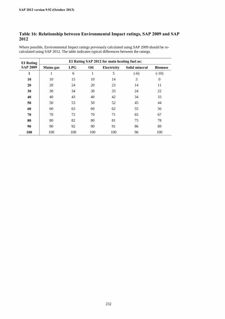
SAP 2012 version 9.92 (October 2013)
232
Table 16: Relationship between Environmental Impact ratings, SAP 2009 and SAP 2012
Where possible, Environmental Impact ratings previously calculated using SAP 2009 should be re-calculated using SAP 2012. The table indicates typical differences between the ratings.
EI Rating SAP 2012 for main heating fuel as: EI Rating SAP 2009 Mains gas LPG Oil Electricity Solid mineral Biomass
1 1 6 1 5 (-6) (-10) 10 10 15 10 14 3 0 20 20 24 20 23 14 11 30 30 34 30 33 24 22 40 40 43 40 42 34 33 50 50 53 50 52 45 44 60 60 63 60 62 55 56 70 70 72 70 71 65 67 80 80 82 80 81 75 78 90 90 92 90 91 86 89
100 100 100 100 100 96 100