Embed Size (px)
Citation preview

SAP Conventions 11 March 2011 (v2.0) Conventions apply to all SAP versions throughout the UK except where otherwise indicated under 'Limitations'. Conventions applied for design stage calculations submitted to building control may be carried through to the as-built stage. New and amended conventions for v2.0 indicated by light blue background. Note. This list will be extended as appropriate. # Limitations Topic Conventions Issue date
GENERAL
1.01 Default values SAP provides default values for many items, such as window U-values and boiler efficiency.
Whenever specific product information is available, that should be used rather than default values.
However when using any specific values there needs to be documentary evidence to support them, and such evidence should be made available to building control on request. For items using the database, the evidence required is that the specific named product, e.g. boiler, is the one being used.
Issued Sept 2010
1.02 Not Scotland Pressure test (as-built assessment)
The as-built assessment cannot be processed unless
(a) pressure test data is provided, either for the dwelling concerned or on another of the same type in the same development, or
(b) in England & Wales the special conditions of AD L1A 2010 paragraph 5.23, or AD L1A 2006 paragraph 63, apply, or
(c) In Northern Ireland the special conditions of TB F1 2006 paragraph 2.54 apply, or
(d) specific dispensation has been given by Building Control.
Issued Sept 2010
amended March 2011
11 March 2011 (v2.0) Page 1 of 24

11 March 2011 (v2.0) Page 2 of 24
# Limitations Topic Conventions Issue date
1.03 Not Scotland Regulations compliance report
As a minimum, building control should be provided with: - the regulations compliance report, and - listing of the input data list, and - PEA (if design stage, E&W only) or EPC (if as-built stage).
They should also be supplied with any supporting information that they may request. The compliance report may show a fail under some headings; in these circumstances it is the decision of building control as to whether or not they approve the construction.
Any differences between the as-designed specification and the as-built specification should be highlighted on the input data list.
(Note. In Scotland, assessment of compliance with CO2 emissions is at the design stage, prior to issue of building warrant. Production of a compliance report is not mandatory but should be considered good practice, where generated by the SAP software.)
Issued Sept 2010
amended March 2011

11 March 2011 (v2.0) Page 3 of 24
# Limitations Topic Conventions Issue date
1.04 England & Wales only
When to issue an EPC
The Predicted Energy Assessment (PEA) is appropriate for all developers selling dwellings off-plan. PEAs should be replaced with an EPC once the dwelling is physically complete. A dwelling is deemed ‘physically complete’ when all of the following conditions are met:
a) Commissioning of the heating system has been satisfactorily completed, and
b) Accredited details are signed off, and
c) Air permeability is confirmed via pressure testing of representative dwellings, and
d) The dwelling itself is complete and could be pressure tested.
It is the developer’s responsibility to use the PEA until a dwelling is physically complete, at which time they should feed information about changes from the design stage to the as-built stage to the OCDEA so that an EPC can be produced. You should not produce an EPC without such information. However, you may find you need to prompt the developer to produce the required information.
Provide a copy of the EPC to the client (in electronic or paper form) as well as the RRN, to be passed to the building control body.
(Note. In Scotland, on completion of building works, the EPC must also be affixed within the completed dwelling. A copy of the EPC must be provided to the verifier with the completion certificate for each new dwelling. The EPC must reflect any variations or additional information, such as air infiltration test results, arising during the construction phase).
Issued Sept 2010
amended March 2011
1.05 SAP version for EPCs
EPCs are always produced using the latest SAP version. If the dwelling concerned was assessed for building regulation compliance using an earlier SAP version the data is transferred to a SAP calculator that uses the current SAP version for EPC production.
EXCEPTION UNTIL 17 APRIL 2011: All EPCs are generated using SAP 2005.
Issued Sept 2010
1.07 SAP 2009
England & Wales only
Design water use For new build in England & Wales it is now required that the dwelling is designed to use not more than 125 litres/person/day for compliance with E&W Part G. SAP assessors may assume that building control will establish compliance with E&W Part G and tick the applicable box in SAP software for new dwellings in England & Wales.
In other countries, and for any existing dwelling, this option does not apply.
Issued Sept 2010

11 March 2011 (v2.0) Page 4 of 24
# Limitations Topic Conventions Issue date
DIMENSIONS
2.01 Average storey height
Where there are rooms extending into the roof space, the average storey height is needed for the volume calculation. This is the average height of the habitable area (plus the thickness of the intermediate floor if it is the upper storey of a house).
Issued Sept 2010
2.02 Storey height of flats over garages
In the case of a flat over an unheated garage (or similar) where the entrance to the flat is on the ground floor with a heated stairway leading to the main part of the flat (see Figure 1 at the end of these conventions), an exception is made to the rule in 2.01:
a) The intermediate floor thickness is added to the ground floor height (dimension X in Figure 1);
b) The first floor height is measured from internal floor to ceiling (dimension Y in Figure 1).
Issued Sept 2010
OPENINGS
3.01 U values of doors to unheated spaces
It is generally not necessary to adjust the U-values of doors in semi-exposed walls, in particular when the area of the element covered by the unheated space is less than 10% of the total exposed area of all external walls.
In some cases (such as a flat with very small external elements) the door may be more than 10%, in which case the U-value of the door in the semi-exposed wall should be adjusted in the same way as that for a semi-exposed wall (SAP documentation section 3.3.2).
Note: Attached garages are disregarded altogether.
Issued Sept 2010
VENTILATION
4.01 Mixed centralised and decentralised mechanical ventilation
Where there is a mixed mechanical system, e.g. consisting of two centralised MEV systems or a centralised MEV system serving part of the dwelling and decentralised MEV serving the remainder, the data for the two systems are combined and the result entered into SAP software. A spreadsheet to assist the process is available from www.bre.co.uk/sap2009.
Issued Sept 2010
4.02 Mechanical ventilation but no data for the number of wet rooms
If there is mechanical ventilation but no data for the number of wet rooms served, use the default data (SAP Table 4g).
Issued Sept 2010

11 March 2011 (v2.0) Page 5 of 24
# Limitations Topic Conventions Issue date
4.03 Solar ventilation Solar powered vents should be entered into SAP software as passive vents. Issued Sept 2010
U-VALUES AND HEAT LOSS
5.01 Correct U-value calculations
U-values are calculated using the conventions given in BR 443.
The SAP assessor should establish the specification of the construction for each element and should satisfy himself that the U-values used in the calculation are correct. Acceptable routes are:
- calculation provided by a person accredited for U-value calculations
- calculation undertaken by the assessor
- calculation provided by another party and checked by the assessor
Issued Sept 2010
amended March 2011
5.02 England & Wales only
Swimming pools In England & Wales U-values of swimming pool basins need to be checked for building control applications from 1 October 2010. However for entry into the SAP calculator the U-value of the floor is to be obtained as if the swimming pool were not there.
Issued Sept 2010
amended March 2011

11 March 2011 (v2.0) Page 6 of 24
# Limitations Topic Conventions Issue date
5.03 SAP 2009 Party wall U-values In the context of U-values, ‘party wall’ includes any wall between the dwelling and another heated space which can be: - another dwelling - commercial premises - a heated corridor or stairwell in a block of flats - a heated common area
The only U-values at present for party walls are 0, 0.2 and 0.5. This applies to both flats and houses regardless of construction type (masonry, timber frame etc)
A solid party wall has U = 0.
Where the party wall is closed at ceiling level by a robust construction element such as a concrete floor slab (not a mineral wool cavity barrier) the U-value is 0.2.
U = 0.5 should be used for all other party walls unless documentary evidence is provided in which case:
To qualify for U = 0.2 (effective edge sealing): - the sealing must prevent air going in or out of the cavity - the sealing required top and bottom and vertically.
To qualify for U = 0: - the cavity must be sealed as above, and - the cavity must be fully filled
Issued Sept 2010
5.04 Window U-values The U-value is that of the complete window, not that of the glazing alone.
It is acceptable to use an average U-value, as long as the U-value used is based upon a standard Glass and Glazing Federation (GGF) 1230 x 1480 mm test window in accordance with BS EN ISO 10077-1. The GGF window is a two-pane window with one open and one fixed pane. However, it is preferable to assign a specific U-value to individual windows (which manufacturers can usually provide). If the design has large areas of glazing a better DER usually results by using individual window U-values (and individual frame factors for solar gain).
Issued Sept 2010

11 March 2011 (v2.0) Page 7 of 24
# Limitations Topic Conventions Issue date
5.05 SAP 2005 Thermal bridging For SAP 2005 and associated building regulations a y-value can be used if it is:
(a) the default value of 0.15; or
(b) a value of 0.08 if the builder confirms in writing that all junctions conform with Accredited Construction Details (ACD, see weblinks at the end of these conventions), or
(c) a value of 0.04 if the builder confirms in writing that Enhanced Construction Details (ECD, see weblinks at the end of these conventions) have been used, or
(d) derived from HTB calculated following the rules in SAP 2005 Appendix K, or
(e) calculated for another dwelling that is identical except for orientation.
Issued Sept 2010
Re-written March 2011

11 March 2011 (v2.0) Page 8 of 24
# Limitations Topic Conventions Issue date
5.06 SAP 2009 Thermal bridging, general
For SAP 2009 and building regulation standards based on SAP 2009 the transmission heat transfer coefficient associated with non-repeating thermal bridges HTB must be calculated, or the calculation verified, by the SAP assessor; a y value can only be used if it is:
(a) the default value of 0.15, or
(b) derived from HTB calculated following the rules in SAP 2009 Appendix K, or
(c) calculated for another dwelling that is identical except for orientation.
When calculating thermal bridges at either design or as-built stage: All bridging types listed in SAP Table K1 and in these conventions should be considered. Evidence is required for values other than the defaults in SAP Table K1. Junction types that are neither listed in SAP Table K1 nor in these conventions are disregarded.
At the design stage: For a junction to be assigned a psi value for an Accredited Construction Detail (ACD) or an Enhanced Construction Detail (ECD) (see weblinks at the end of these conventions) for the purposes of SAP calculations, a list of the intended junction detail reference numbers should be confirmed by the client. The thermal bridging should be specified using (a), (b) or (c) above.
At the as-built stage: For a junction to be assigned a psi value for an Accredited Construction Detail (ACD) or an Enhanced Construction Detail (ECD) (see weblinks at the end of these conventions) for the purposes of SAP calculations, confirmation is needed from the builder that the specific junction has been built in accordance with Accredited Construction Details and that the associated checklists have been completed. A list of the junction detail reference numbers should be confirmed by the client. The values for the design stage are used provided that (a) they were fully specified at the design stage and (b) it is confirmed that no design alterations were made.
Issued Sept 2010
Re-written March 2011

11 March 2011 (v2.0) Page 9 of 24
# Limitations Topic Conventions Issue date
5.07 SAP 2009 Thermal bridging, sources of psi values
The psi value for each junction is obtained from:
1. For any junction for which an ACD is being used use the applicable psi value in the ‘accredited’ column in Table K1, or
2. For any junction for which an ECD is being used use the psi value associated with the junction reference number, or
3. For any junction for which a calculated psi value is provided, this may be used subject to written confirmation that the calculation was performed by someone with suitable experience and expertise defined in AD L1A paragraph 5.12, or
4. If none of the above applies for any junction, use the psi value for the applicable junction type in the ‘default’ column in Table K1.
The factors (0.02 or 25% whichever is the larger) stated in Approved Document L1A and SAP Appendix K are not applicable at present (until the Government announces that thermal bridging ‘schemes’ are launched). Also, these factors are not applied in Scotland.
Values for accredited details can be used only for those junctions with an ACD/ECD reference number. If a psi value for any junction is not available use the applicable default value from Table K1.
When there is more than one type of a given junction type which have different psi values (e.g. corners in the main dwelling and stud wall corner in a roof room; multiple types of lintel), either: (a) use the highest psi value for the junction type with the total length, or
(b) calculate a weighted average (psi value for each type weighted by the length of each type) and enter the result into the SAP calculator along with the total length.
March 2011
5.08 SAP 2009 Thermal bridging, additional junction types
For the treatment of - elements adjacent to an unheated space - dormers - bay windows - roofs with parapets see Appendix A to these conventions.
March 2011

11 March 2011 (v2.0) Page 10 of 24
# Limitations Topic Conventions Issue date
5.09 SAP 2009 Thermal mass The Thermal Mass Parameter (TMP) required for calculations by SAP 2009. It can be:
a. calculated from the areas and kappa values of each element, including party walls, party floors and party ceilings and both sides of internal partitions (which include internal walls and intermediate floors), or
b. entered into software as a TMP value that has been calculated as in a. (for example using a spreadsheet), or
c. treated as being low, medium or high using the global values of 100, 250 or 450 kJ/m²K given in SAP 2009 Table 1f.
Guidelines for selection of values for c. are:
- timber frame and AAC or lightweight masonry construction is usually low;
- it is medium if there are dense blocks in external or partition walls;
- it is high if at least two of external wall, internal partition wall, party wall have dense blocks
- internal insulation makes it low irrespective of the construction;
- in all of the above, only the innermost 100 mm of the construction influences the thermal mass
If the choice is unclear, consult Table 1 at the end of these conventions.
In case of a dispute, a detailed calculation via a. or b. should be undertaken.
Issued Sept 2010
SPACE HEATING
6.01 Micro-CHP If the system is unavailable in the database, select condensing boiler with SAP default efficiency.
Issued Sept 2010

11 March 2011 (v2.0) Page 11 of 24
# Limitations Topic Conventions Issue date
6.02 SAP 2009 Two main heating systems
Although in the large majority of cases there is only one main heating system, SAP 2009 provides for two main systems.
A second main system is not to be confused with a secondary heater. The latter are rooms heater(s) heating individual room(s) either as a supplement to the main heating in the room (e.g. a wood burning stove in the main room) or for rooms not heated by the main system.
A main system is generally one that would be described as central heating (a heat generator providing heat to several rooms via a heat distribution system), although the term does also include for example storage heaters and fixed direct-acting heaters in each room.
When there are two main systems, system 1 always heats the living area.
Issued Sept 2010
6.03 SAP 2009 Two solid fuel boilers Where there are two solid fuel boilers feeding the same distribution system, the fraction of heat should be taken as 0.5 from each.
Issued Sept 2010
6.04 SAP 2009 Boiler using liquid biofuel
The boiler must be found in the Product Characteristic Data File for the fuel concerned. Issued Sept 2010
6.05 Community heating systems
SAP assessors need to obtain details of heat generators, distribution loss, etc from the system designers.
Issued Sept 2010
6.06 CHP supplying both dwellings and commercial buildings
Where a CHP system is providing heat to the block of flats (domestic hot water) and electricity to commercial premises, the electricity generation must be credited only once.
a) If the electricity generated is included in the assessment of the commercial premises only the CHP heat efficiency is be entered into the SAP software (electrical efficiency is zero or heat-to-power ratio of 10,000).
b) If the electricity generated is not included in the assessment of the commercial premises both the CHP heat and electrical efficiencies are entered into the SAP software.
Issued Sept 2010

11 March 2011 (v2.0) Page 12 of 24
# Limitations Topic Conventions Issue date
DHW HEATING
7.01 SAP 2009 Separate boiler for DHW
Sometimes there is a separate boiler providing DHW only. If there is information about it in the PCDF, it can be entered into SAP software as follows:
- two main systems - main system 1 is that providing space heating - main system 2 is that DHW boiler - fraction of main heat from system 2 is zero - water heating from main system 2.
Issued Sept 2010
7.02 More than one hot water system
Except in the case of heat pump systems, solid fuel room heaters with back boilers and where there is solar water heating, it is only possible to include one water heating system in the SAP 2005 or SAP 2009 calculation. In the event of there being more than one specified, the one selected should be that which is intended to heat most of the hot water, e.g. an immersion heater that is provided primarily as a backup should be disregarded.
Issued Sept 2010
7.03 Independent programming of DHW heating
Many heating system programmers have a single channel time control with a separate switch that can be set to ‘H/W only’, ‘H/W and space heating’, ‘Space heating only’ and similar combinations. Such a device does not provide independent programming of the hot water. In order to qualify as water separately timed it must be possible to program the space heating for two or more time periods a day and the hot water to be programmed for at least two different periods per day. This requires a time switch or programmer with more than one time control channel.
Issued Sept 2010
RENEWABLES
8.01 SAP 2005 Multiple PV orientations
Where there are two PV arrays with different orientation:
- collect data for the two sets of PVs, getting the kWp, tilt, orientation and overshading for each one;
- apply equation M1 in SAP Appendix M to each; and
- add the resulting kWh/year figures.
A spreadsheet is available www.bre.co.uk/sap2009 to assist making the above calculation. Once all relevant data has been entered, the spreadsheet gives instructions as to what to enter into the SAP calculator for the installed peak power (kWp), collector orientation, collector tilt and overshading of the PV system.
Issued Sept 2010
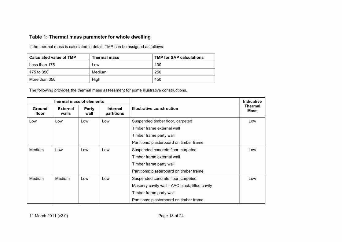
Table 1: Thermal mass parameter for whole dwelling If the thermal mass is calculated in detail, TMP can be assigned as follows: Calculated value of TMP Thermal mass TMP for SAP calculations
Less than 175 Low 100
175 to 350 Medium 250
More than 350 High 450 The following provides the thermal mass assessment for some illustrative constructions.
Thermal mass of elements
Ground floor
External walls
Party wall
Internal partitions
Illustrative construction
IndicativeThermal
Mass
Low Low Low Low Suspended timber floor, carpeted
Timber frame external wall
Timber frame party wall
Partitions: plasterboard on timber frame
Low
Medium
Low Low Low Suspended concrete floor, carpeted
Timber frame external wall
Timber frame party wall
Partitions: plasterboard on timber frame
Low
Medium
Medium Low
Low Suspended concrete floor, carpeted
Masonry cavity wall - AAC block, filled cavity
Timber frame party wall
Partitions: plasterboard on timber frame
Low
11 March 2011 (v2.0) Page 13 of 24

11 March 2011 (v2.0) Page 14 of 24
Thermal mass of elements
Ground floor
External walls
Party wall
Internal partitions
Illustrative construction
IndicativeThermal
Mass
Medium
Medium Medium
Low Suspended concrete floor, carpeted
Masonry cavity wall - AAC block, filled cavity
AAC party wall
Partitions: plasterboard on timber frame.
Medium
Medium
Medium Medium
Medium Suspended concrete floor, carpeted
Masonry cavity wall - AAC block, filled cavity
AAC party wall
Partitions: medium block, plasterboard on dabs
Medium
High
Medium Medium
Medium Slab on ground, carpeted
Masonry cavity wall - AAC block, filled cavity
AAC party wall
Partitions: dense block, plasterboard on dabs
Medium
High
High Medium
Medium Slab on ground, carpeted
Masonry cavity wall - dense block, filled cavity
AAC party wall
Partitions: medium block, plasterboard on dabs
Medium
High
High High Medium Slab on ground, carpeted
Masonry cavity wall - dense block, filled cavity
Dense block party wall
Partitions: medium block, plasterboard on dabs
High

11 March 2011 (v2.0) Page 15 of 24
Thermal mass of elements
Ground floor
External walls
Party wall
Internal partitions
Illustrative construction
IndicativeThermal
Mass
High
High High High Slab on ground, carpeted
Masonry cavity wall - dense block, filled cavity
Dense block party wall
Partitions: dense block, dense plaster
High

Figure 1
Heated stairway
Floor
Flat
Unheated garage
Floor
Y
X
11 March 2011 (v2.0) Page 16 of 24

11 March 2011 (v2.0) Page 17 of 24
Weblinks for thermal bridge details
ACD: England & Wales: www.planningportal.gov.uk/buildingregulations/approveddocuments/partl/bcassociateddocuments9/acd Scotland: www.scotland.gov.uk/Topics/Built-Environment/Building/Building-standards/profinfo/techguide/acdscot The Scotland ones can be used in England & Wales if the actual construction corresponds.
ECD: www.energysavingtrust.org.uk/business/Business/Housing-professionals/Interactive-tools/Enhanced-Construction-Details/Enhanced-Construction-Details-Matrix Revision history September 2010 First issue
Conventions: 1.01 to 1.07, 2.01 to 2.02, 3.01, 4.01 to 4.03, 5.01 to 5.07, 6.01 to 6.06, 7.01 to 7.03, 8.01
March 2011 Second issue
Re-numbered: 5.07 to 5.09
Amended: 1.02, 1.03, 1.04, 1.07, 5.01, 5.02, 5.03, 5.05, 5.06
1.06 deleted pending clarification
Added: 5.07, 5.08, Appendix 1
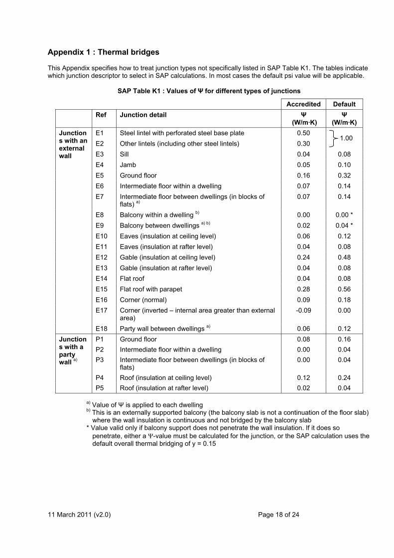
Appendix 1 : Thermal bridges This Appendix specifies how to treat junction types not specifically listed in SAP Table K1. The tables indicate which junction descriptor to select in SAP calculations. In most cases the default psi value will be applicable.
SAP Table K1 : Values of Ψ for different types of junctions
Accredited Default Ref Junction detail Ψ
(W/m·K) Ψ
(W/m·K) E1 Steel lintel with perforated steel base plate 0.50 E2 Other lintels (including other steel lintels) 0.30
1.00
E3 Sill 0.04 0.08 E4 Jamb 0.05 0.10 E5 Ground floor 0.16 0.32 E6 Intermediate floor within a dwelling 0.07 0.14 E7 Intermediate floor between dwellings (in blocks of
flats) a) 0.07 0.14
E8 Balcony within a dwelling b) 0.00 0.00 * E9 Balcony between dwellings a) b) 0.02 0.04 * E10 Eaves (insulation at ceiling level) 0.06 0.12 E11 Eaves (insulation at rafter level) 0.04 0.08 E12 Gable (insulation at ceiling level) 0.24 0.48 E13 Gable (insulation at rafter level) 0.04 0.08 E14 Flat roof 0.04 0.08 E15 Flat roof with parapet 0.28 0.56 E16 Corner (normal) 0.09 0.18 E17 Corner (inverted – internal area greater than external
area) -0.09 0.00
Junctions with an external wall
E18 Party wall between dwellings a) 0.06 0.12 P1 Ground floor 0.08 0.16 P2 Intermediate floor within a dwelling 0.00 0.04 P3 Intermediate floor between dwellings (in blocks of
flats) 0.00 0.04
P4 Roof (insulation at ceiling level) 0.12 0.24
Junctions with a party wall a)
P5 Roof (insulation at rafter level) 0.02 0.04
a) Value of Ψ is applied to each dwelling b) This is an externally supported balcony (the balcony slab is not a continuation of the floor slab)
where the wall insulation is continuous and not bridged by the balcony slab * Value valid only if balcony support does not penetrate the wall insulation. If it does so
penetrate, either a Ψ-value must be calculated for the junction, or the SAP calculation uses the default overall thermal bridging of y = 0.15
11 March 2011 (v2.0) Page 18 of 24

11 March 2011 (v2.0) Page 19 of 24
Elements adjacent to unheated spaces
Elements adjacent to unheated spaces
Junction Reference in SAP Table K1
Exposed upper floors and floors above garages E5
Floor above heated space E7
Floor above unheated space E5
Walls adjacent to heated corridors / stairwells, or other heated space: treat as party walls.
E18
Walls adjacent to garages (or other unheated space) walls: treat as external walls.
E16
Walls adjacent to enclosed unheated corridors / stairwells: treat as external walls.
E16
Dormers See also Figures A1 and A2.
Dormers
Junction Reference in SAP Table K1
Wall of dormer / Roof of dormer, insulation at ceiling
E10 and E12
Wall of dormer / Roof of dormer, insulation at rafters
E11 and E13
Corner wall of dormer E16
Inverted corner E17 Junctions where the dormer meets the main structure are disregarded.

Figure A1
11 March 2011 (v2.0) Page 20 of 24

Figure A2
11 March 2011 (v2.0) Page 21 of 24

11 March 2011 (v2.0) Page 22 of 24
Bay windows Junctions between walls:
- If the insulation is continuous the junctions are disregarded.
- If not continuous insulation, use the default values from SAP Table K1 for junctions between two walls (E16 and E17).
Junctions of wall with ground floor, intermediate floor and roof: according to the following table.
Bay windows – walls to ground floor, intermediate floor and roof
Junction of wall of bay window with: Reference in SAP Table K1
Ground floor E5
Intermediate floor E6
Flat roof E14
Pitched roof, insulation at ceiling level E10
Pitched roof, insulation at rafter level E11 Junctions between two roofs Disregarded. Parapet on flat roof There are separate psi values in SAP Table K1 for flat roofs with and without a parapet..
From the thermal bridging point of view the principal difference between a parapet and not is whether the wall passes over the edge of the roof, or the roof passes over the top of the wall. These two possibilities form different types of junction.
If the wall passes over the edge of the roof, treat as a roof with parapet.
If the roof passes over the top of the wall, treat it as a roof without a parapet.

Heated basement
11 March 2011 (v2.0) Page 23 of 24

Roof room
Partial flat roof
11 March 2011 (v2.0) Page 24 of 24