Embed Size (px)
Citation preview
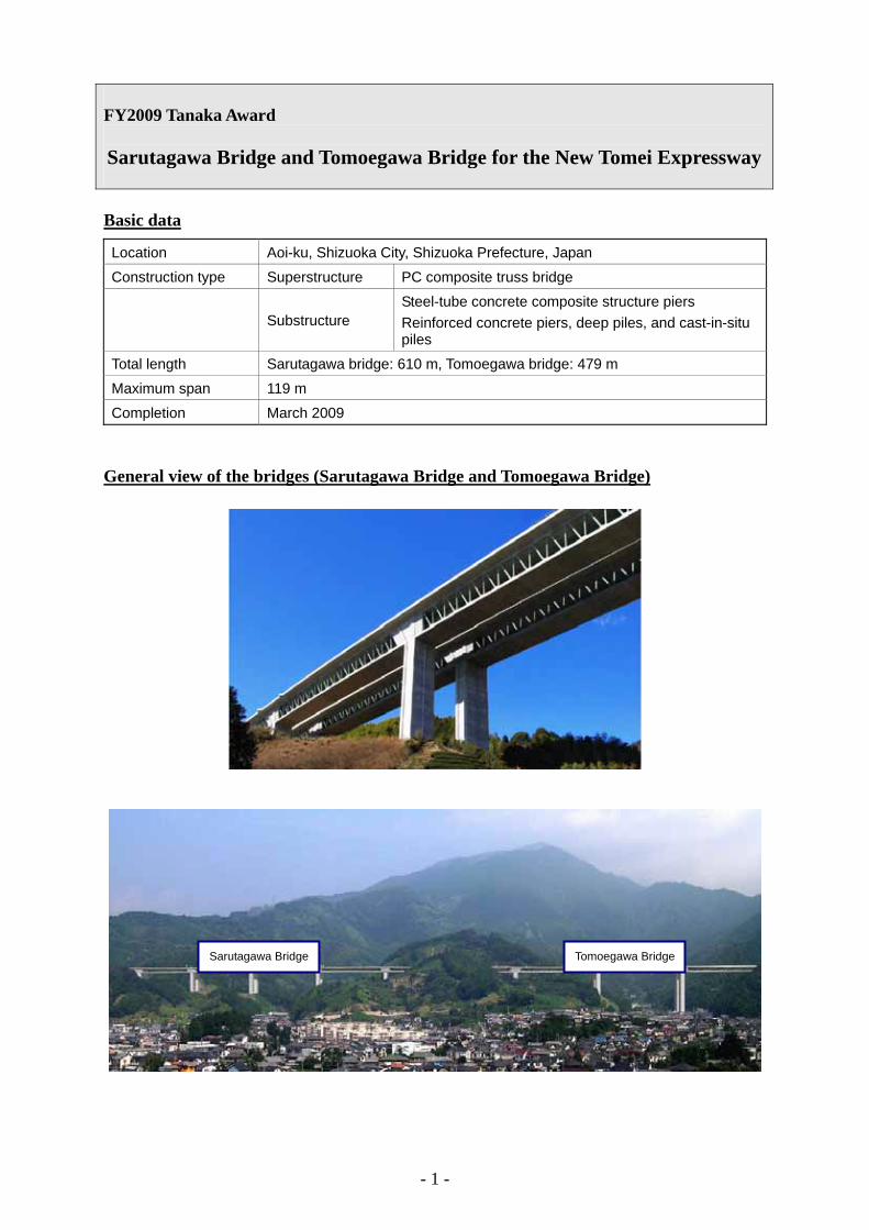
FY2009 Tanaka Award Sarutagawa Bridge and Tomoegawa Bridge for the New Tomei Expressway Basic data
Location Aoi-ku, Shizuoka City, Shizuoka Prefecture, Japan
Construction type Superstructure PC composite truss bridge
Substructure Steel-tube concrete composite structure piers Reinforced concrete piers, deep piles, and cast-in-situ piles
Total length Sarutagawa bridge: 610 m, Tomoegawa bridge: 479 m
Maximum span 119 m
Completion March 2009 General view of the bridges (Sarutagawa Bridge and Tomoegawa Bridge)
Tomoegawa Bridge
Sarutagawa Bridge
- 1 -

Location
New Tomei Expressway
Shizuoka
Sarutagawa Bridge and Tomoegawa Bridge
Outline The Sarutagawa Bridge and Tomoegawa Bridge are river bridges located between
Yoshihara JCT and Shizuoka IC (provisional names) constructed for the New Tomei Expressway. The total length of the bridges is approximately 1.2 km (including the civil work section about 65 m). The construction site is visible from as far as the center of Shizuoka city and also lies close to a residential area. Under these circumstances, so that the bridges will blend in with the surrounding landscape and to impart a lightweight impression, the bridges were constructed by introducing a PC composite truss structure into their superstructure for the first time in Japan. Furthermore, considering that the location is in the area where disaster prevention measures are strictly enforced, the overall seismic capacity was enhanced in the bridges through 1) slender shape of superstructure, 2) adoption of steel-pipe concrete composite structural piers, and 3) rigid connection of super- and substructures. The foundations and piers were erected by employing a ring beam-guided earth retaining work method, with the aim of reducing excavation size and thus minimizing alterations to nature.
In the construction work, attention was paid to management points specific to PC
composite truss bridge construction and in order to achieve higher construction accuracy and shorter work period, adjustment of construction machinery and review of execution procedures were carried out as needed.
In the outbound lane work which commenced in advance, the development of nodal
structures, actual bridge loading testing, analytical verification, and other tasks were performed, and the adequacy of the design technique employed for the PC composite truss bridges and the safety of their structures were verified. Particularly for the nodal structures to serve as a critical structural element, in pursuit of the rationality in terms of structure and construction, two types of nodal structures, a double-tube nodal structure and a two-face gusset nodal structure, were newly developed while verifying with prototype experimental study and then applied to the bridges. In the following inbound lane work, the knowledge acquired from the inbound lane work was utilized and for further pursuit of rationality, a reduced number of main truss systems (decreased from four to three main truss systems), compact nodal structure construction, and other achievements were worked out.
- 2 -

Tomoegawa Bridge [Outbound lane]
Sarutagawa Bridge
Fig.-1 Steel and concrete composite truss bridges
Technological features (1) PC composite truss bridge PC composite truss bridge consists of a web structure built with steel truss members in
place of a standard concrete web and has upper and lower concrete slabs. Characteristics:
1) Lightweight superstructure: → Compact sized foundation structure and substructure
→ Enhanced seismic capacity 2) Less heavyweight impression,
and airy image: → Alleviated sense of oppression to the to the
residents in the vicinity → The distinctive shapes of the bridges are
created as “monumental architecture.”
Nodal point Lower concrete slab
Concrete stringer
Steel truss member
Outer cable
Inner cable
Upper concrete slab
- 3 -

(2) Technological development up to the completion of the PC composite truss bridges PC composite truss bridge is a bridge structure developed overseas and its construction
was introduced in this project for the first time in Japan. Under these circumstances, various studies were conducted ranging from review of design methods to the development of nodal structures to function as a connection between concrete and steel truss, and the establishment of an work execution plan to ensure construction accuracy, quality, and adherence to work schedule.
Further, further rationality in the design and construction of the succeeding inbound lane
was attained, drawing on the knowledge obtained from the preceding inbound lane work. ◆ Establishment of design method
Design based on the analysis of three-dimensional frames built with modeled members Design of details by actively employing 3D FEM analysis
Verification with actual bridges
- 4 -

◆ Development of nodal structure
Steel truss member
PBL and through reinforcing steel
Gusset plate
Verification testing of nodal structure performance 1/2-sized model
Connecting plate
“Two-face gusset nodal structure” which imparts high yield strength
Perforated steel tube with inner and outer ribs
Outer ribbed stetube
el
Steel truss
“Double-tube nodal structure” which excels in constructability
◆ Rationality Quality, constructability, and economy were analyzed for the outbound lane work and the
results of the analysis were used to enhance rationality in the design and construction for the inbound lane.
Subsequent inbound lane work
Preceding outbound lane work
Three main truss system
Four main truss system
- 5 -
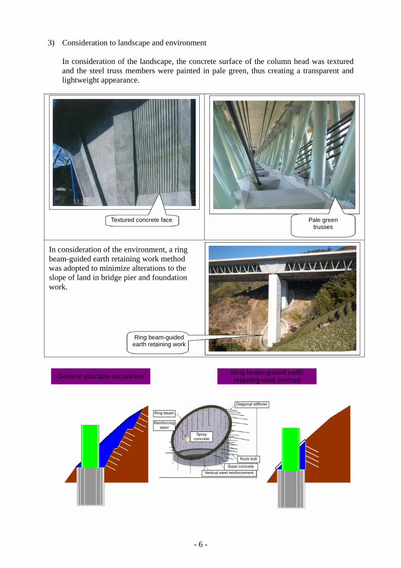
3) Consideration to landscape and environment In consideration of the landscape, the concrete surface of the column head was textured
and the steel truss members were painted in pale green, thus creating a transparent and lightweight appearance.
Textured concrete face Pale green trusses
In consideration of the environment, a ring beam-guided earth retaining work method was adopted to minimize alterations to the slope of land in bridge pier and foundation work.
Ring beam-guided earth retaining work
Vertical steel reinforcementBase concrete
Rock bolt
Spray concrete
Reinforcing steel
Diagonal stiffener
Ring beam
Ring beam-guided earth retaining work method
General structure excavation
- 6 -

Overview of Construction
Photo-1 Steel-tube concrete composite structure bridge pier
Photo-2 Column head completed
- 7 -

Photo-3 Overhangs under erection
Photo-4 Closure in the central part
- 8 -