Embed Size (px)
Citation preview

SAS Progressive withAtronic Display Link (ADL)
Rev. 1.1

2April 2007 | rev.1.1
AD
L -
Atronic
Dis
pla
y L
ink
Document Information
Document type: Technical Information
Target group: qualified technical personnel
Document title: SAS Progressive with Atronic Display Link (ADL)
Revision: 1.1
Release: April 2007
Copyright Notice:© 2007, Atronic. All rights reserved.No part of this publication may be copied or distributed, transmitted, transcribed,stored in a retrieval system, or translated into any human or computer language, in anyform or by any means, electronic, mechanical, magnetic, manual, or otherwise, ordisclosed to third parties without the express written permission obtained from a properlyauthorized official of Atronic.
DISCLAIMERAtronic makes no representation or warranties, express or implied, with respect tothis publication, or any product of Atronic, including but not limited to warranties ofmerchantability or fitness for any particular purpose. Atronic reserves the right tomake changes, enhancements, revisions and alterations of any kind to this publicationor the product(s) it covers without obligation to notify any person, institution ororganization of such changes, enhancements, revisions and alterations.
TRADEMARKSThis document may contain trademarks of Atronic. All other brand and product namesare trademarks or registered trademarks of their respective companies.
Document Information
3April 2007 | rev.1.1
AD
L -
Atronic
Dis
pla
y L
ink
ABOUT THIS MANUAL
ScopeThis document describes how to set up and configure a SAS progressive withthe Atronic Display Link (ADL). It describes how to set up the participatinggaming machines, how to link them and how to carry out the jackpot configuration.
Target AudienceWe address qualified technical personnel, who are involved in setup andconfiguration of a system progressive link. With this user group we assume thatthey are basically computer literate and familiar with gaming machine and pro-gressive jackpot terminology.
Please read this document carefully before you start, to avoid incorrectconfiguration.
What is the Atronic Display Link (ADL) about?The ADL is a hardware interface that has been developed by Atronic to operatea multilevel system progressive jackpot link. The machines are linked with standardCAT-5 network cables, using a RS485 bus interface, which is implemented to theAtronic commboard.
To operate more than 16 gaming machines in an Atronic multilevel jackpot link(e.g. Cash Fever™, Game of Life® or King Kong Cash™) it is mandatory to set upthe link as a system progressive. The jackpot values and increments are determinedby an extern jackpot controller.
Atronic linked gaming concepts comes with a signage which features one or twoplasma or LCD displays. The display(s) are driven by the Media Controller, whichis a small PC with a customized display software. If a bonus feature entry orjackpot hit has been triggered, the Media Controller starts the correspondingoverhead display animation.
The ADL ensures that a jackpot hit or bonus feature entry within a systemprogressive link is broadcasted to the master machine which is connected to theMedia Controller.
Important!If a Cash Fever™ link is operated as an system progressive jackpot link with ADL,it is not possible to prevent "meter overtake"!
ADL | Introduction

4April 2007 | rev.1.1
AD
L -
Atronic
Dis
pla
y L
ink
ADL | Setup
CABLING
ADL Wiring DiagrammThis figure shows a wiring diagramm of a typical ADL link with up to 16 machines.The APL/ADL power supply can be connected to each end of the link.
If more than 16 machines are to be linked, the APL/ADL power supply has to beconnected in the middle of the link using a RJ45 Y-adapter Adapter WE8-2 WE8.
UPSunit
SignagePC
Display 1 Display 2
Monitor Out
Audio Out
Converter
MDC
BSO
MDC
BSO
MDC
BSO
APLPowerSupply
GM 1Master
GM 16ADL Slave
GM 17ADL Slave
AdapterWE8 - 2 WE8
MDC
BSO
GM 32ADL Slave
Legend | GM: Gaming Machine | ADL: Atronic Display Link | MDC: Machine Data Controller | EP: Earth Print | BSO: Base Socket | PFU: Power Feeding Unit
Floo
rN
etw
ork
TCP/
IP
PFU
PowerSupply
HUB
EPEP EP EP
SignagePC
Display 1 Display 2
Monitor Out
Audio Out
Converter
MDC
BSO
MDC
BSO
MDC
BSO
APLPowerSupply
Floo
rN
etw
ork
TCP/
IP
GM 1Master EPEP
GM 2ADL Slave
GM 16ADL Slave EP
PFU
PowerSupply
HUB
UPSunit
Legend | GM: Gaming Machine | ADL: Atronic Display Link | MDC: Machine Data Controller | EP: Earth Print | BSO: Base Socket | PFU: Power Feeding Unit
5April 2007 | rev1.1
AD
L -
Atronic
Dis
pla
y L
ink
P5
P18
P9
P10
P7
P3
P15
P12 P4P19
P11
P14
P13P2
P20
S1 S2 S3 S4 S6 S7 S5 S8
S9
5V
12V
U34 U35
U28
0
5
1
23
46
78
90
5
1
23
46
78
90
5
1
23
46
78
90
5
1
23
46
78
90
5
1
23
46
78
90
5
1
23
46
78
9
1 2 3 4 5 6 7 8
ON
1 2 3 4 5 6 7 8
ON
Battery 3.6V +
P1
B1CPU 68k
P17
P16
P4P31
P2
Overhead Display Board
Commboard 68kRev. 2.10
Not
connected
Converter
P5
P18
P9
P10
P7
P3
P15
P12 P4P19
P11
P14
P13P2
P20
S1 S2 S3 S4 S6 S7 S5 S8
S9
5V
12V
U34 U35
U28
0
5
1
23
46
78
90
5
1
23
46
78
90
5
1
23
46
78
90
5
1
23
46
78
90
5
1
23
46
78
90
5
1
23
46
78
9
1 2 3 4 5 6 7 8
ON
1 2 3 4 5 6 7 8
ON
Battery 3.6V +
P1
B1CPU 68k
P17
P16
Commboard 68kRev. 2.10
P5
P18
P9
P10
P7
P3
P15
P12 P4P19
P11
P14
P13P2
P20
S1 S2 S3 S4 S6 S7 S5 S8
S9
5V
12V
U34 U35
U28
0
5
1
23
46
78
90
5
1
23
46
78
90
5
1
23
46
78
90
5
1
23
46
78
90
5
1
23
46
78
90
5
1
23
46
78
9
1 2 3 4 5 6 7 8
ON
1 2 3 4 5 6 7 8
ON
Battery 3.6V +
P1
B1CPU 68k
P17
P16
Commboard 68kRev. 2.10
APL Power Supply
MA
STE
RSLA
VE
SLA
VE
MachineData Controller
(MDC)
MachineData Controller
(MDC)
MachineData Controller
(MDC)
connect tomains
connect tosignage PC
CABLING
Commboard Wiring Diagramm
Connector P10 and P11As connectors P10 and P11 on the commboardare wired parallel, it does not matter which one isused for input or output. However it isrecommended to use this wiring pattern for easeof maintenance.
CAT-5 Network cable
SAS Channel 1 OutputConnect P12 of each commboard to aMDC (Machine Data Controller) or a SMIB(slot machine interface board) to connectthe machine to the floor network.
ADL MasterThe Media Controller has to be connectedto the commboard of the ADL mastermachine.
ADL | Setup

6April 2007 | rev1.1
AD
L -
Atronic
Dis
pla
y L
ink
COMMBOARD SETUP
This section describes how to set up thecommboards in a SAS progressive with ADL link.It describes required settings to operate ADL.
The commboard is located in the logic box (cardcage) of the machine. It is the topmost board. Pullthe green release lever to remove the commboard(with the machine switched off). The commboardsetup has to be done with the machine switchedoff.
Important: Do not remove, insert orconfigure the commboard or themainboard with the machine switched on.
Following settings are described on the next pages:
Required Settings
• Activate system progressive mode and con-figure the gaming machine ID´s.
• Activate ADL mode and configure an ADLmaster machine.
• Communication to an online system via a slotmachine interface board (SMIB).
Optional Settings
• SAS dual channel communication.
• Lock machine, if the online system is notconnected.
Commboard
ADL | Setup
7April 2007 | rev1.1
AD
L -
Atronic
Dis
pla
y L
ink
COMMBOARD SETUP
Required SettingsFollowing commboard settings are required tooperate a SAS progressive with ADL.
Activate SAS progressive with ADL mode andconfigure an ADL master machine.
1.Set an ADL Progressive Address with rotaryswitches S1 and S2 on the commboard. Eachmachine in the link must have a unique addressfrom "01" to "32". Address "00" is not valid.
S1: Set ADL Progressive Address x10S2: Set ADL Progressive Address x 1
2.Enable SAS channel 1 communication viacommboard connector P12 (RS-232 interface)or connector P2 (TTL interface) with rotaryswitches S6 and S7 on the commboard.
If the accounting system address is determinedby a MDC or SMIB set rotary switch S7 to 1.
If the accounting system address is notdetermined by a MDC or SMIB it is mandatoryto set for each machine a unique address!
S6: Set Accounting System Address x 10S7: Set Accounting System Address x 1
Example: To set ADL Pro-gressive Address "15", setS1 to "1" and S2 to "5"
P7
P13P2
P20
S1 S2 S3 S4 S6 S7 S5 S8
U34 U35
0
5
1
23
46
78
90
5
1
23
46
78
90
5
1
23
46
78
90
5
1
23
46
78
90
5
1
23
46
78
90
5
1
23
46
78
9
1 2 3 4 5 6 7 8
ON
1 2 3 4 5 6 7 8
ON
Battery 3.6V +
P1
Commboard 68kRev. 2.10
Example: To set AccountingSystem Address "15", setS6 to "1" and S7 to "5"
Note: Close jumper B1 onthe commboard if you use anAtronic Systems MDC.
ADL | Setup

8April 2007 | rev1.1
AD
L -
Atronic
Dis
pla
y L
ink
COMMBOARD SETUP
3.Configure commboard DIP switch S5 / 1 - 3.(on all commboards in the link)Set S5 / 1 to ONSet S5 / 2 to ONSet S5 / 3 to ONThis activates the SAS progressive with ADLmode in general.
4.Configure one commboard in the link as ADLmaster:Set S5 / 4 to ONThis sets ADL master mode and activates thelink functionality.
Note: The Media Controller has to be connectedto the ADL master commboard.
On all other (ADL slave) commboards S5 / 4has to be set to OFF.
5.Set S5 /6 to ONThis enables communication to an online systemin general.
DIP switch overview
S5
Rotary switches
5ShctiwS noitcnuF1-5 2-5 3-5
NO NO NO )semagdeknilrof(LDAhtiwevissergorPSAS
4-5
NO retsaMsatcaMGELPA *
FFO evalSsatcaMGELPA *
6-5
NO metsySgnitnuoccAdetnemelpmietavitcA
FFO metsySgnitnuoccAdetnemelpmielbasiD
hctiwS noitcnuF1S sserddAmetsySevissergorPsMGE **
2S sserddAmetsySevissergorPsMGE **
6S 1lennahCsserddAmetsySgnitnuoccAsMGE ***
7S 1lennahCsserddAmetsySgnitnuoccAsMGE ***
ADL | Setup
S5MASTER
1 2 3 4 5 6 7 8
ON
S5SLAVE
1 2 3 4 5 6 7 8
ON
9April 2007 | rev1.1
AD
L -
Atronic
Dis
pla
y L
ink
COMMBOARD SETUP
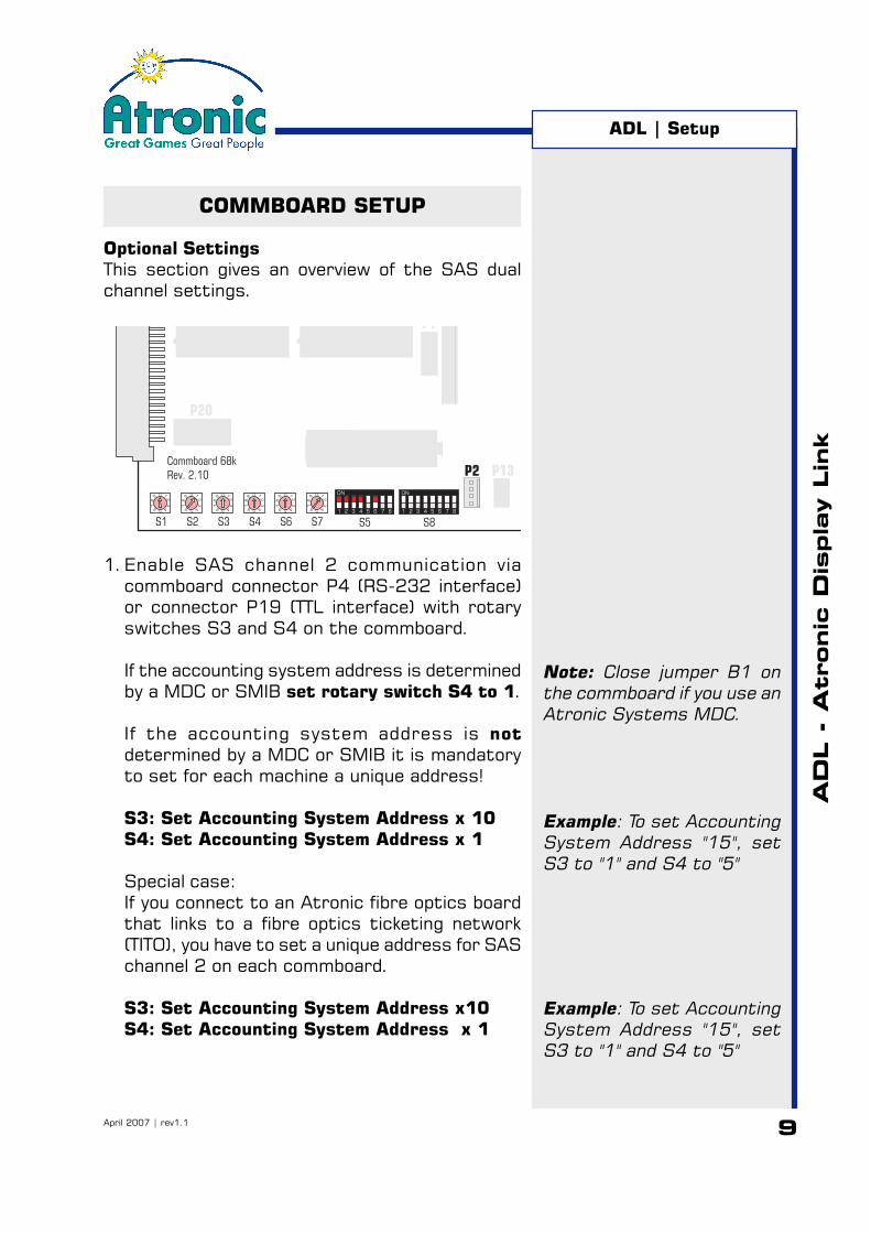
Optional SettingsThis section gives an overview of the SAS dualchannel settings.
1.Enable SAS channel 2 communication viacommboard connector P4 (RS-232 interface)or connector P19 (TTL interface) with rotaryswitches S3 and S4 on the commboard.
If the accounting system address is determinedby a MDC or SMIB set rotary switch S4 to 1.
If the accounting system address is notdetermined by a MDC or SMIB it is mandatoryto set for each machine a unique address!
S3: Set Accounting System Address x 10S4: Set Accounting System Address x 1
Special case:If you connect to an Atronic fibre optics boardthat links to a fibre optics ticketing network(TITO), you have to set a unique address for SASchannel 2 on each commboard.
S3: Set Accounting System Address x10S4: Set Accounting System Address x 1
P7
P13P2
P20
S1 S2 S3 S4 S6 S7 S5 S8
U34 U35
0
5
1
23
46
78
90
5
1
23
46
78
90
5
1
23
46
78
90
5
1
23
46
78
90
5
1
23
46
78
90
5
1
23
46
78
9
1 2 3 4 5 6 7 8
ON
1 2 3 4 5 6 7 8
ON
Battery 3.6V +
P1
Commboard 68kRev. 2.10
ADL | Setup
Example: To set AccountingSystem Address "15", setS3 to "1" and S4 to "5"
Note: Close jumper B1 onthe commboard if you use anAtronic Systems MDC.
Example: To set AccountingSystem Address "15", setS3 to "1" and S4 to "5"

10April 2007 | rev1.1
AD
L -
Atronic
Dis
pla
y L
ink
COMMBOARD SETUP
Optional SettingsSAS Dual Channel Communication continued
2.Allocate SAS long polls to a SAS channel.The Atronic commboard 68k allows to allocateparticular SAS long polls to channel 1 or chan-nel 2. This is done with DIP switches S8 / 2 - 6.
Set S8 / 2 - 6 to OFF= SAS channel 1Set S8 / 2 - 6 to ON = SAS channel 2
S8 / 2Allocates Progressive Jackpot PollsAffected long polls: 80, 86
S8 / 3Allocates EFT PollsAffected long polls: 22-26, 28, 29, 62-67
S8 / 4Allocates Legacy Bonusing PollsAffected long polls: 2E, 8A, 8B
S8 / 5Allocates Control PollsAffected long polls: 03-07, 0A-0C, 94, A8
S8 / 6Allocates Ticketing Polls and ExceptionsAffected long polls: 4C, 4D, 57, 58, 70, 71, 7DAffected exceptions:3F, 57, 67, 68
Lock machine if the online system is notconnected
Set DIP switch S8 / 8 to ON to force a machinelock, if the commboard does not receive broad-casts from the online system for more than 15seconds. In this case an error message is dis-played on screen and all play is locked.
With S8 / 8 set to OFF (default) the machineremains playable without communication to theonline system.
ADL | Setup
11April 2007 | rev1.1
AD
L -
Atronic
Dis
pla
y L
ink
Note: Although an ADL slavemachine can send progres-sive jackpot values to theMedia Controller, it has to beconnected to the ADLmaster. Only the ADLmaster can send the triggersignal to start the jackpothit presentation.
MEDIA CONTROLLER SETUP
This section describes how to connect the MediaController and the plasma/LCD display(s).
GeneralThe Media Controller is a small PC that providesvideo animations and jackpot values which aredisplayed on the plasma/LCD display(s). Twodisplays and a audio device can be connected. Themains voltage for the Media Controller is providedby an Uninterruptible Power Supply (UPS).
The Media Controller receives jackpot broadcastsand bonus feature entries from the ADL mastermachine and starts the appropriate videoanimations. It is connected by a RS485-to-RS232converter and a small commboard add-on board,the OH Displayboard.
Media Controller LocationThe Media Controller has to be connected to theADL master machine. It is recommended to situatethe Media Controller and its UPS in the base standof the ADL master machine.
Important: The base stand or boxwhere the Media Controller is situatedhas to be actively vented to preventthe Media Controller from overheating.The environmental temperature mustnot exceed 40°C/104°F.
Signage CablingThe VGA cable, the audio cable and the signagemains cable is usually threaded through one of theposts that hold the signage. You may need totemporarily remove the signage mains plug tothread it through the post.
The plasma/LCD display(s) which are connected tothe Media Controller have to support a 1024 x768 pixel display resolution at 60 Hz with highest(32 bit) color quality via VGA (RGB) connector.
ADL | Setup
12April 2007 | rev1.1
AD
L -
Atronic
Dis
pla
y L
ink
MEDIA CONTROLLER SETUP
This section describes how to connect the MediaController. As the signage type may vary thesesteps are described in general.
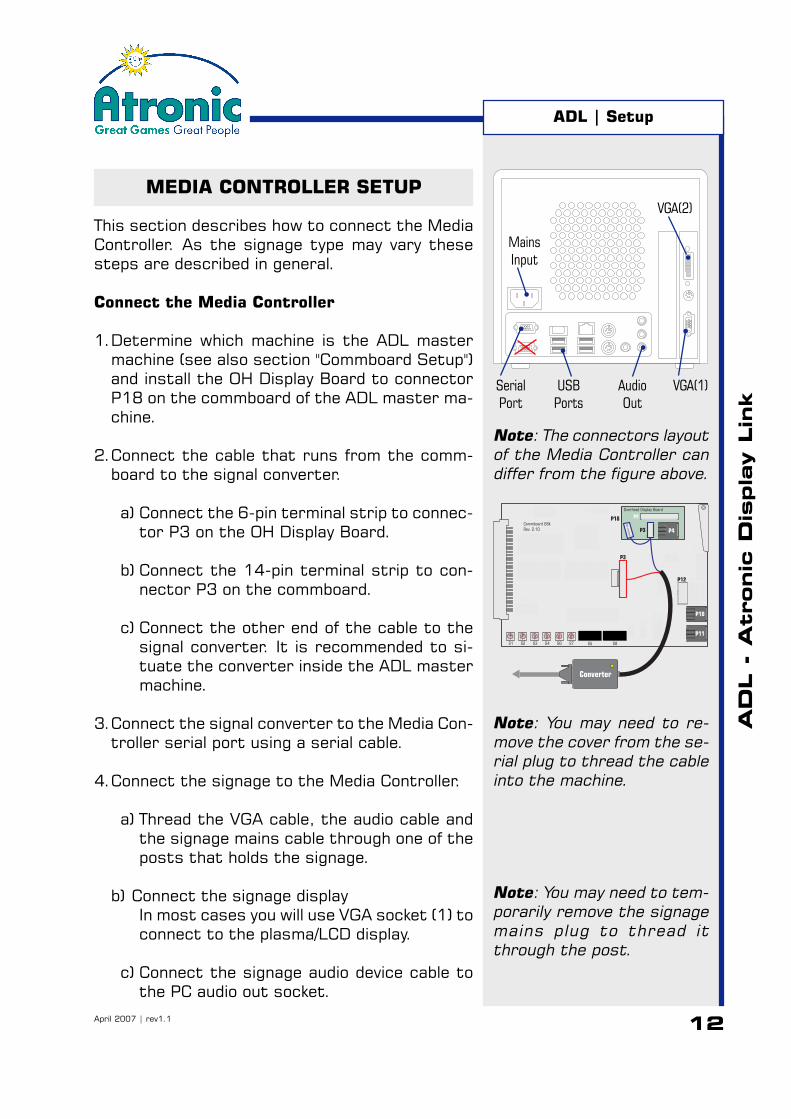
Connect the Media Controller
1.Determine which machine is the ADL mastermachine (see also section "Commboard Setup")and install the OH Display Board to connectorP18 on the commboard of the ADL master ma-chine.
2.Connect the cable that runs from the comm-board to the signal converter.
a) Connect the 6-pin terminal strip to connec-tor P3 on the OH Display Board.
b) Connect the 14-pin terminal strip to con-nector P3 on the commboard.
c) Connect the other end of the cable to thesignal converter. It is recommended to si-tuate the converter inside the ADL mastermachine.
3.Connect the signal converter to the Media Con-troller serial port using a serial cable.
4.Connect the signage to the Media Controller.
a) Thread the VGA cable, the audio cable andthe signage mains cable through one of theposts that holds the signage.
b) Connect the signage displayIn most cases you will use VGA socket (1) toconnect to the plasma/LCD display.
c) Connect the signage audio device cable tothe PC audio out socket.
Note: You may need to re-move the cover from the se-rial plug to thread the cableinto the machine.
Note: You may need to tem-porarily remove the signagemains plug to thread itthrough the post.
P5
P18
P9
P10
P7
P3
P15
P12 P4P19
P11
P14
P13P2
P20
S1 S2 S3 S4 S6 S7 S5 S8
S9
5V
12V
U34 U35
U28
0
5
1
23
46
78
90
5
1
23
46
78
90
5
1
23
46
78
90
5
1
23
46
78
90
5
1
23
46
78
90
5
1
23
46
78
9
1 2 3 4 5 6 7 8
ON
1 2 3 4 5 6 7 8
ON
Battery 3.6V +
P1
B1CPU 68k
P17
P16
P4P31
P2
Overhead Display Board
Commboard 68kRev. 2.10
Not
connected
Converter
Note: The connectors layoutof the Media Controller candiffer from the figure above.
SerialPort
USBPorts
AudioOut
VGA(1)
VGA(2)
MainsInput
ADL | Setup
13April 2007 | rev1.1
AD
L -
Atronic
Dis
pla
y L
ink
ADL | Setup
MEDIA CONTROLLER SETUP
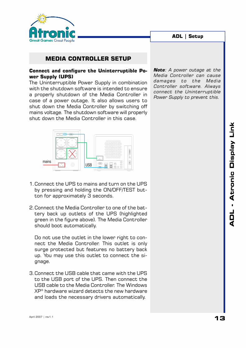
Connect and configure the Uninterruptible Po-wer Supply (UPS)The Uninterruptible Power Supply in combinationwith the shutdown software is intended to ensurea properly shutdown of the Media Controller incase of a power outage. It also allows users toshut down the Media Controller by switching offmains voltage. The shutdown software will properlyshut down the Media Controller in this case.
1.Connect the UPS to mains and turn on the UPSby pressing and holding the ON/OFF/TEST but-ton for approximately 3 seconds.
2.Connect the Media Controller to one of the bat-tery back up outlets of the UPS (highlightedgreen in the figure above). The Media Controllershould boot automatically.
Do not use the outlet in the lower right to con-nect the Media Controller. This outlet is onlysurge protected but features no battery backup. You may use this outlet to connect the si-gnage.
3.Connect the USB cable that came with the UPSto the USB port of the UPS. Then connect theUSB cable to the Media Controller. The WindowsXP® hardware wizard detects the new hardwareand loads the necessary drivers automatically.
Note: A power outage at theMedia Controller can causedamages to the MediaController software. Alwaysconnect the UninterruptiblePower Supply to prevent this.
mainsUSB
14April 2007 | rev1.1
AD
L -
Atronic
Dis
pla
y L
ink
MEDIA CONTROLLER SETUP
Install and configure the shutdown software
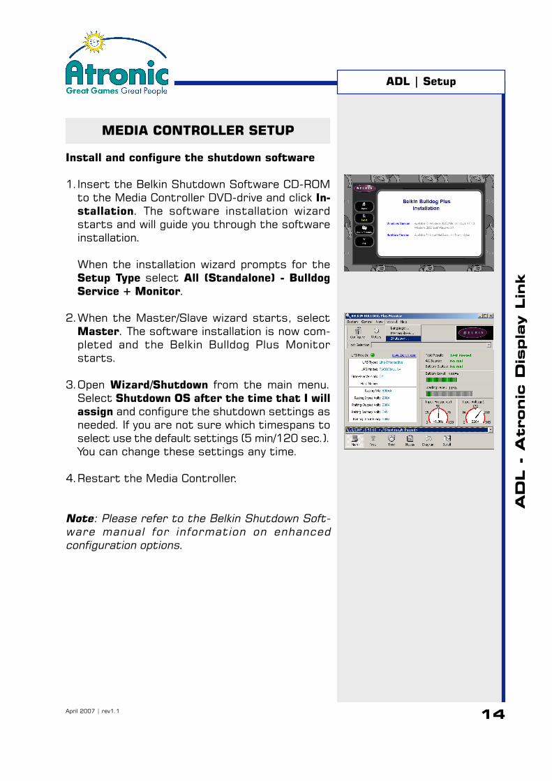
1.Insert the Belkin Shutdown Software CD-ROMto the Media Controller DVD-drive and click In-stallation. The software installation wizardstarts and will guide you through the softwareinstallation.
When the installation wizard prompts for theSetup Type select All (Standalone) - BulldogService + Monitor.
2.When the Master/Slave wizard starts, selectMaster. The software installation is now com-pleted and the Belkin Bulldog Plus Monitorstarts.
3.Open Wizard/Shutdown from the main menu.Select Shutdown OS after the time that I willassign and configure the shutdown settings asneeded. If you are not sure which timespans toselect use the default settings (5 min/120 sec.).You can change these settings any time.
4.Restart the Media Controller.
Note: Please refer to the Belkin Shutdown Soft-ware manual for information on enhancedconfiguration options.
ADL | Setup

15April 2007 | rev1.1
AD
L -
Atronic
Dis
pla
y L
ink
MACHINE SETUP
OverviewAtronic machines usually come configured asspecified with the order. However it may benecessary to re-configure basic machine settings,such as denomination, metering, paytable, etc.These settings can not be altered during normaloperation, as they require a machine reinitialisationfor technical or jurisdictional reasons. Applying newprogressive jackpot settings also requires a RAMReset.
ADL | Setup

16April 2007 | rev1.1
AD
L -
Atronic
Dis
pla
y L
ink
MACHINE SETUP
To re-configure basic machine and jackpot settings:
1.Perform a RAM ResetThis will clear all machine data, statistics andsettings, including progressive jackpot configu-ration.
2.Carry out the Initial SetupAfter a RAM Reset has been performed, themachine automatically enters the Initial Setupmenu. The Initial Setup allows to configure allbasic machine setting.
Required initial setup settings
• Player DenominationConfigure only one player denomination! If morethan one player denomination has beenconfigured the machine/link will not operateproperly.
• Set Progressive GroupDepending on the Jackpot controller this settingmay vary.If the Jackpot controller requires the machineprogressive group number, it is necessary toconfigure the same progressive group numberon the machine and the jackpot controller.If the Jackpot controller do not require themachine progressive group number, set theprogressive group number to “1”.
• Commboard RequiredSet Commboard Required to “YES”.
ADL | Setup

17April 2007 | rev1.1
AD
L -
Atronic
Dis
pla
y L
ink
MACHINE SETUP
3.Jackpot ConfigurationAfter the Initial Setup has been carried out, itis necessary to carry out the progressive jack-pot configuration. Do not insert credits beforethe jackpot configuration is done.
In an ADL link the jackpot configuration has tobe carried out at the APL master machine only.The jackpot configuration is then transferred toall linked ADL slave machines.
Required alink setup settings
Set the currency <in machine> according tothe machine configuration.
Set Jackpot Type 1-4 to normal and select save.The jackpot values and increments are providedby the accounting system.
ADL | Setup

18April 2007 | rev1.1
AD
L -
Atronic
Dis
pla
y L
ink
COMMBOARD DIP SWITCH TABLE
Use the tables below to set up progressive systemaddress, accounting system address, progressivemode, APL mode and SAS channel allocation on thecommboard, before you carry out the RAM Reset.
* Configure one gaming machine asmaster and the remaining gamingmachines as slave.
** Configure for each machine aunique progressive systemaddress.
*** If the accounting system addressis determined by a MDC or SMIBset the accounting progressivesystem address to 1 to activatechannel 1.If the accounting system addressis not determined by a MDC orSMIB it is mandatory to set foreach machine a unique address!
hctiwS noitcnuF1S sserddAmetsySevissergorPsMGE **
2S sserddAmetsySevissergorPsMGE **
3S )tesfilennahCdn2elbaneyllacitamotuA(2lennahCsserddAmetsySgnitnuoccAsMGE
4S )tesfilennahCdn2elbaneyllacitamotuA(2lennahCsserddAmetsySgnitnuoccAsMGE
6S 1lennahCsserddAmetsySgnitnuoccAsMGE
7S 1lennahCsserddAmetsySgnitnuoccAsMGE
hctiwS noitcnuF1-5 2-5 3-5
FFO FFO FFO evissergorP01-SMnhokiM
NO FFO FFO evissergorPgnitnuoccA
FFO NO FFO )morpenidedulcnifi(FCLPA/evissergorPLPA
NO NO FFO yretsyM72-SMnhokiM
FFO FFO NO evissergorP+yretsyM72-SMnhokiM
NO FFO NO lennahCdr3metsySgnitnuoccA
FFO NO NO 01-SMnhokiMotstluafed,desuton
NO NO NO )semagdeknilrof(LDAhtiwevissergorPSAS
4-5
NO retsaMsatcaMGELPA *
FFO evalSsatcaMGELPA *
5-5
NO )sretemevissergorpgnikatrevo(1reveFhsaC
FFO )sretemevissergorpgnikatrevo-non(2reveFhsaC
6-5
NO metsySgnitnuoccAdetnemelpmietavitcA
FFO metsySgnitnuoccAdetnemelpmielbasiD
7-5 8-5
NO FFO daertonfinettirwrevotekcitDNAyapdnaH
FFO NO daertonfinettirwrevoeblliwylnoofnitekciT
hctiwS noitpircseD slloPgnoLdetceffA1-8
FFO
NOnoitpmedernopuoclennahC2
)PZE2nahc,lanoitomorpyllab1nahc(
2-8
FFO 1nahcPJgorP 68x0,08x0
NO 2nahcPJgorP
3-8
FFO 1nahcTFE 92x0,82x0,62x0ot22x0
NO 2nahcTFE 92x0,82x0,76x0ot26x0
4-8
FFO 1nahcsunoB B8x0,A8x0,E2x0
NO 2nahcsunoB
5-8
FFO 1nahclortnoC C0x0otA0x0,70x0ot30x0
NO 2nahclortnoC 8Ax0,49x0
6-8
FFO 1nahcnopuoC 17x0,07x0,85x0,75x0,D4x0,C4x0
NO 2nahcnopuoC )86x0,76x0,75x0,F3x0pxE(D7x0
7-8
FFO tsohotretemporDlatoTsdnesBC
NO )yllaB(retempordnioCsdnesBC
8-8
NO detcennoct´nsimetsysgnitnuoccafiegasseM
FFO detcennoct´nsimetsysgnitnuoccafiegassemoN
***
***
ADL | Appendix

19April 2007 | rev1.1
AD
L -
Atronic
Dis
pla
y L
ink
ADL | Appendix
COMMBOARD CONNECTORS
The Atronic commboard 68k Rev. 2.10 featuresseveral connectors for different systems andprotocols.
Connector Interface Protocol / Function
P2 TTL SAS channel 1 (current loop)P3 - Cash-Now trigger signalsP4* RS232 SAS channel 2 or GRIPS™P5 - Comm Key (Ticket in dongle)P7 - External DisplayP9 - +12VP10, P11 RS485 A-LINK™P12 RS232 SAS channel 1P13 TTL Bally® SDS™P14 TTL DACOM®
P15 - not usedP16 RS422 VLC®
P17 - Manufacturer useP18 RS422 Overhead OH DisplayboardP19 TTL SAS channel 2 (current loop)P20 - not used
S9 Close to apply +5V or +12V to pin 1 of connector P2B1 Close jumper to bridge electrical (galvanic) isolation
of SAS connectors (close SAS digital ground toelectrical ground).
*Connector function depends on commboard software protocol version.
Note: Connectors P10 andP11 are parallel wired.
P5
P18
P9
P10
P7
P3
P15
P12 P4P19
P11
P14
P13P2
P20
S1 S2 S3 S4 S6 S7 S5 S8
S9
5V
12V
U34 U35
U28
0
5
1
23
46
78
90
5
1
23
46
78
90
5
1
23
46
78
90
5
1
23
46
78
90
5
1
23
46
78
90
5
1
23
46
78
9
1 2 3 4 5 6 7 8
ON
1 2 3 4 5 6 7 8
ON
Battery 3.6V +
P1
B1CPU 68k
P17
P16
Note: You may close jumperB1 to enhance signal quality,if the connected interfacedevice provides galvanicisolation of groundconnection.
20April 2007 | rev1.1
AD
L -
Atronic
Dis
pla
y L
ink
ADL | Appendix
COMMBOARD CONNECTORS
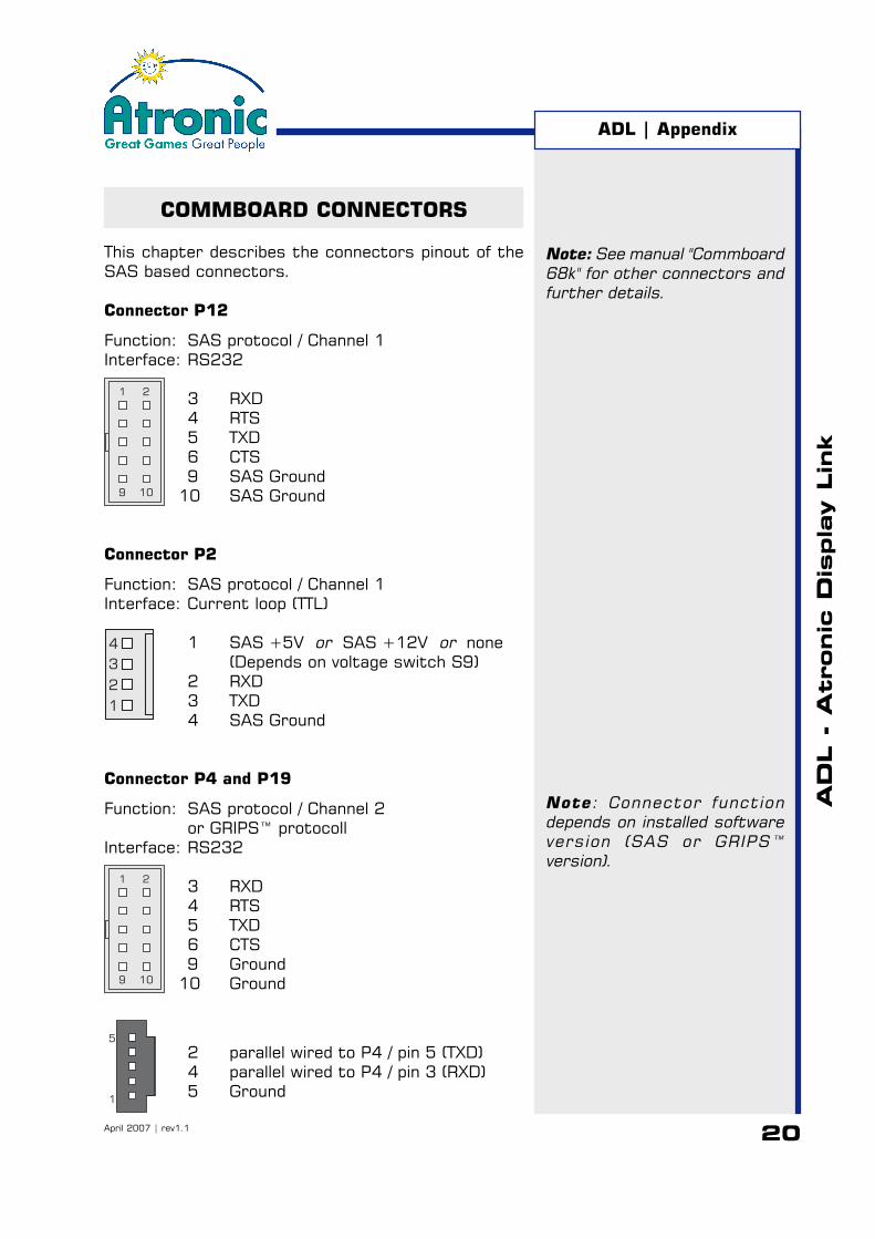
This chapter describes the connectors pinout of theSAS based connectors.
Connector P12
Function: SAS protocol / Channel 1Interface: RS232
3 RXD4 RTS5 TXD6 CTS9 SAS Ground
10 SAS Ground
Connector P2
Function: SAS protocol / Channel 1Interface: Current loop (TTL)
1 SAS +5V or SAS +12V or none(Depends on voltage switch S9)
2 RXD3 TXD4 SAS Ground
Connector P4 and P19
Function: SAS protocol / Channel 2or GRIPS™ protocoll
Interface: RS232
3 RXD4 RTS5 TXD6 CTS9 Ground
10 Ground
2 parallel wired to P4 / pin 5 (TXD)4 parallel wired to P4 / pin 3 (RXD)5 Ground
1
4
3
2
1 2
9 10
1
5
Note: See manual "Commboard68k" for other connectors andfurther details.
1 2
9 10
Note: Connector functiondepends on installed softwareversion (SAS or GRIPS™version).