Embed Size (px)
Citation preview
1
SASY 60i Busbar System
Table of Contents
SASY 60i Busbar System
Busbar supports Page xx
60 mm System Page xx
D-Type Fuse-Bases Page xx
Busbar-Slide Switch-Disconnector-Fuses Page xx
NH-Fuse-Switch-Disconnectors Page xx
Dimensions Page xx
UL/CSA approvals list Page xx
Copper weight, extra charges Page xx
2
SASY 60i Busbar System
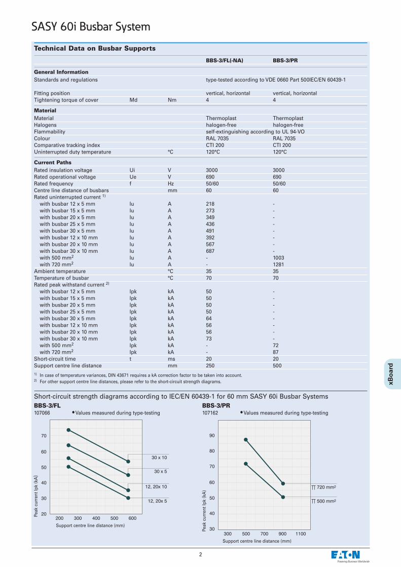
Technical Data on Busbar Supports
BBS-3/FL(-NA) BBS-3/PR
General InformationStandards and regulations type-tested according to VDE 0660 Part 500IEC/EN 60439-1
Fitting position vertical, horizontal vertical, horizontalTightening torque of cover Md Nm 4 4
MaterialMaterial Thermoplast ThermoplastHalogens halogen-free halogen-freeFlammability self-extinguishing according to UL 94-VOColour RAL 7035 RAL 7035Comparative tracking index CTI 200 CTI 200Uninterrupted duty temperature °C 120°C 120°C
Current PathsRated insulation voltage Ui V 3000 3000Rated operational voltage Ue V 690 690Rated frequency f Hz 50/60 50/60Centre line distance of busbars mm 60 60Rated uninterrupted current 1)
with busbar 12 x 5 mm Iu A 218 -with busbar 15 x 5 mm Iu A 273 -with busbar 20 x 5 mm Iu A 349 -with busbar 25 x 5 mm Iu A 436 -with busbar 30 x 5 mm Iu A 491 -with busbar 12 x 10 mm Iu A 392 -with busbar 20 x 10 mm Iu A 567 -with busbar 30 x 10 mm Iu A 687 -with 500 mm2 Iu A - 1003with 720 mm2 Iu A - 1281
Ambient temperature °C 35 35Temperature of busbar °C 70 70Rated peak withstand current 2)
with busbar 12 x 5 mm Ipk kA 50 -with busbar 15 x 5 mm Ipk kA 50 -with busbar 20 x 5 mm Ipk kA 50 -with busbar 25 x 5 mm Ipk kA 50 -with busbar 30 x 5 mm Ipk kA 64 -with busbar 12 x 10 mm Ipk kA 56 -with busbar 20 x 10 mm Ipk kA 56 -with busbar 30 x 10 mm Ipk kA 73 -with 500 mm2 Ipk kA - 72with 720 mm2 Ipk kA - 87
Short-circuit time t ms 20 20Support centre line distance mm 250 5001) In case of temperature variances, DIN 43671 requires a kA correction factor to be taken into account. 2) For other support centre line distances, please refer to the short-circuit strength diagrams.
BBS-3/FL 107066 • Values measured during type-testing
Short-circuit strength diagrams according to IEC/EN 60439-1 for 60 mm SASY 60i Busbar Systems BBS-3/PR107162 • Values measured during type-testing
Peak
cur
rent
Ipk
(kA
)
Peak
cur
rent
Ipk
(kA
)
Support centre line distance (mm)
Support centre line distance (mm)

3
SASY 60i Busbar System
BBS-3/FL-NA107067 • Values measured during type-testing
Short-circuit strength diagrams according to UL 845 for 60 mm SASY 60i Busbar Systems BBS-3/PR107162 • Values measured during type-testing
Current load TT 500 mm2
Current load TT 720 mm2
Peak
cur
rent
Ir.m
.s. (
RM
S) i
n kA
Peak
cur
rent
Ir.m
.s. (
RM
S) i
n kA
Support centre line distance (mm) Support centre line distance (mm)
Rate
d co
nsta
nt c
urre
nt Iu
in A
Busbar temperature Ts in °C
Rate
d co
nsta
nt c
urre
nt Iu
in A
Busbar temperature Ts in °C
Ambient temperature °C
Ambient temperature °C

4
SASY 60i Busbar System
Technical Data on the 60 mm System
Conductor connections The ratios between conductor cross-sections in mm2 and AWG/MCM-sizes are listed below:1.5 mm2 16 AWG2.5 mm2 14 AWG4 mm2 12 AWG6 mm2 10 AWG10 mm2 8 AWG16 mm2 6 AWG25 mm2 4 AWG35 mm2 2 AWG50 mm2 0 AWG70 mm2 2/0 AWG95 mm2 3/0 AWG120 mm2 250 MCM150 mm2 300 MCM185 mm2 350 MCM240 mm2 500 MCM300 mm2 600 MCM
Busbar supports60 mm system according to IEC1-pole for busbars 12x5 – 30x10, double-T-bars2-pole for busbars 12x5 – 30x103-pole for busbars 12x5 – 30x10 and 12/20/ 30 x 5/103-pole for double-T-barsTighten screws for fixing the cover and bottom of the support at a torque of 4 Nm min.
60 mm system according to UL3-pole for busbars 12/20/ 30 x 5/103-pole for double-T-bars Tighten screws for fixing the cover and bottom of the support at a torque of 4 Nm min.
Silicone-free, chlorine-free Temperature resistant up to 120°CSelf-extinguishing according to UL 94Comparative tracking index CTI 200
Busbars according to DIN EN 13601Tin-plated Cu-bars significantly reduce the work necessary for preparing the contact points. Cu-busbars are effectively protected against aggressive environments.
Dimension Cross-sectionDouble-T 500 mm2
Double-T 720 mm2
Permissible tolerances:Radius R 0.3 … 0.7Width: + 0.1 / – 0.5Thickness: + 0.1 / – 0.1
Center line distance:± 0.5 mm (60 mm system)Variance on the contacting level: 0.4 mm
Ampacity with copper barsCross-sections of bars Surface Ampacity according to IEC Ampacity according to UL/CSAmm mm2 35°C ambient temperature A
65°C bar temperatureA
12 x 5 60 200 20020 x 5 100 320 32030 x 5 150 450 45012 x 10 120 360 36020 x 10 200 520 52030 x 10 300 630 630Double-T 500 950 950Double-T 720 1200 1200
5
SASY 60i Busbar System
Technical Data on the 60 mm System
Busbars according to DIN EN 13601For busbar applications that have not been type-tested, UL508A allows an ampacity of 1000A/inch2 (1.55A/mm²) if no tests have been carried out. This value may be higher if the product or the application has been tested accordingly. Moeller has conducted extensivetests for the user’s maximum benefit in using the SASY 60i busbar system. The advantage of such tests is that one can use the SASY60ibusbar system with higher rated currents than the default value allows. A busbar of size 30x10 mm for example can be charged with 630Ainstead of 465A only.Higher current carrying capacities to DIN 43671 were obtained under operating conditions. Busbar temperature is normally positively influenced by mounting components on the busbar and by air circulation within the installa-tion. Depending on the respective ambient temperature, you can calculate the correction factor k2 according to DIN 43 671 for flat busbars. Ifambient conditions change, a correction factor needs to be taken into account.On the other hand, increased loads may occur if the components feature a correspondingly high temperature resistance. A 30 x 10 tin-plated busbar can under normal conditions be loaded with 630 A . With a load of 800A, for instance, a k2 correction factor of1.3 is necessary. It follows from the diagram that with this factor and 35° C air temperature, the busbar heats up to approx. 85°C.
Base plate Silicone-free, chlorine-free Temperature resistant up to 110°CSelf-extinguishing according to UL 94
Busbar coversfor busbars of 12 x 5, 12–30 x 5, 12–30 x 10Double-T-profiles
Silicone-free, chlorine-free Temperature resistant up to 110°CSelf-extinguishing according to UL 94
Modular system coverto be attached to 60 mm systems, 3-poleto busbars of 12/20/30 x 5/10, 25 x 5,to double-T-profiles
Cover profile frontCover profile top/bottomCover profile support
Silicone-free, chlorine-free Temperature resistant up to 120°CSelf-extinguishing according to UL 94
6
SASY 60i Busbar System
Technical Data on the 60 mm System
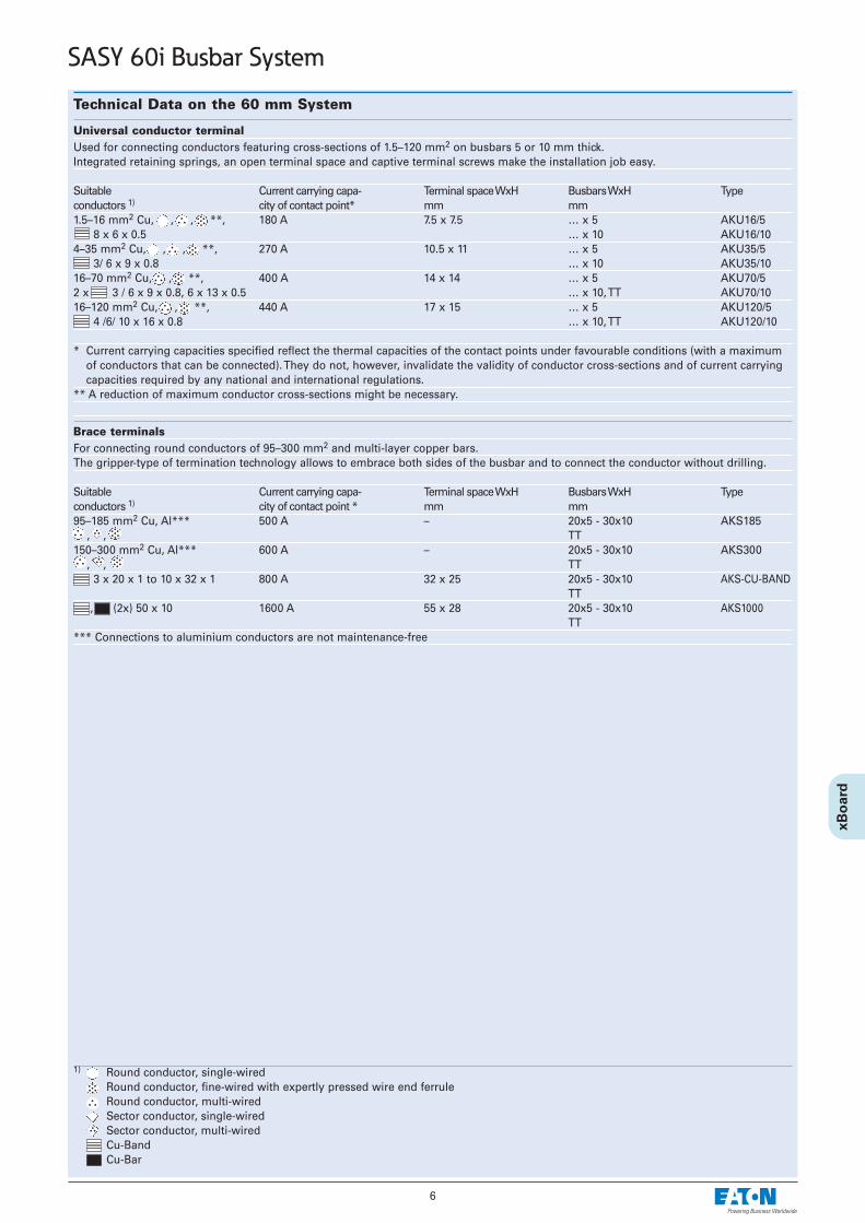
Universal conductor terminalUsed for connecting conductors featuring cross-sections of 1.5–120 mm2 on busbars 5 or 10 mm thick. Integrated retaining springs, an open terminal space and captive terminal screws make the installation job easy.
Suitable Current carrying capa- Terminal space WxH Busbars WxH Typeconductors 1) city of contact point* mm mm1.5–16 mm2 Cu, , , **, 180 A 7.5 x 7.5 … x 5 AKU16/5
8 x 6 x 0.5 … x 10 AKU16/104–35 mm2 Cu, , , **, 270 A 10.5 x 11 … x 5 AKU35/5
3/ 6 x 9 x 0.8 … x 10 AKU35/1016–70 mm2 Cu, , **, 400 A 14 x 14 … x 5 AKU70/52 x 3 / 6 x 9 x 0.8, 6 x 13 x 0.5 … x 10, TT AKU70/1016–120 mm2 Cu, , **, 440 A 17 x 15 … x 5 AKU120/5
4 /6/ 10 x 16 x 0.8 … x 10, TT AKU120/10
* Current carrying capacities specified reflect the thermal capacities of the contact points under favourable conditions (with a maximumof conductors that can be connected). They do not, however, invalidate the validity of conductor cross-sections and of current carryingcapacities required by any national and international regulations.
** A reduction of maximum conductor cross-sections might be necessary.
Brace terminalsFor connecting round conductors of 95–300 mm2 and multi-layer copper bars.The gripper-type of termination technology allows to embrace both sides of the busbar and to connect the conductor without drilling.
Suitable Current carrying capa- Terminal space WxH Busbars WxH Typeconductors 1) city of contact point * mm mm95–185 mm2 Cu, Al*** 500 A – 20x5 - 30x10 AKS185
, , TT150–300 mm2 Cu, Al*** 600 A – 20x5 - 30x10 AKS300
, , TT3 x 20 x 1 to 10 x 32 x 1 800 A 32 x 25 20x5 - 30x10 AKS-CU-BAND
TT, (2x) 50 x 10 1600 A 55 x 28 20x5 - 30x10 AKS1000
TT*** Connections to aluminium conductors are not maintenance-free
1) Round conductor, single-wired Round conductor, fine-wired with expertly pressed wire end ferruleRound conductor, multi-wiredSector conductor, single-wired Sector conductor, multi-wired Cu-BandCu-Bar
7
SASY 60i Busbar System
Technical Data on the 60 mm System
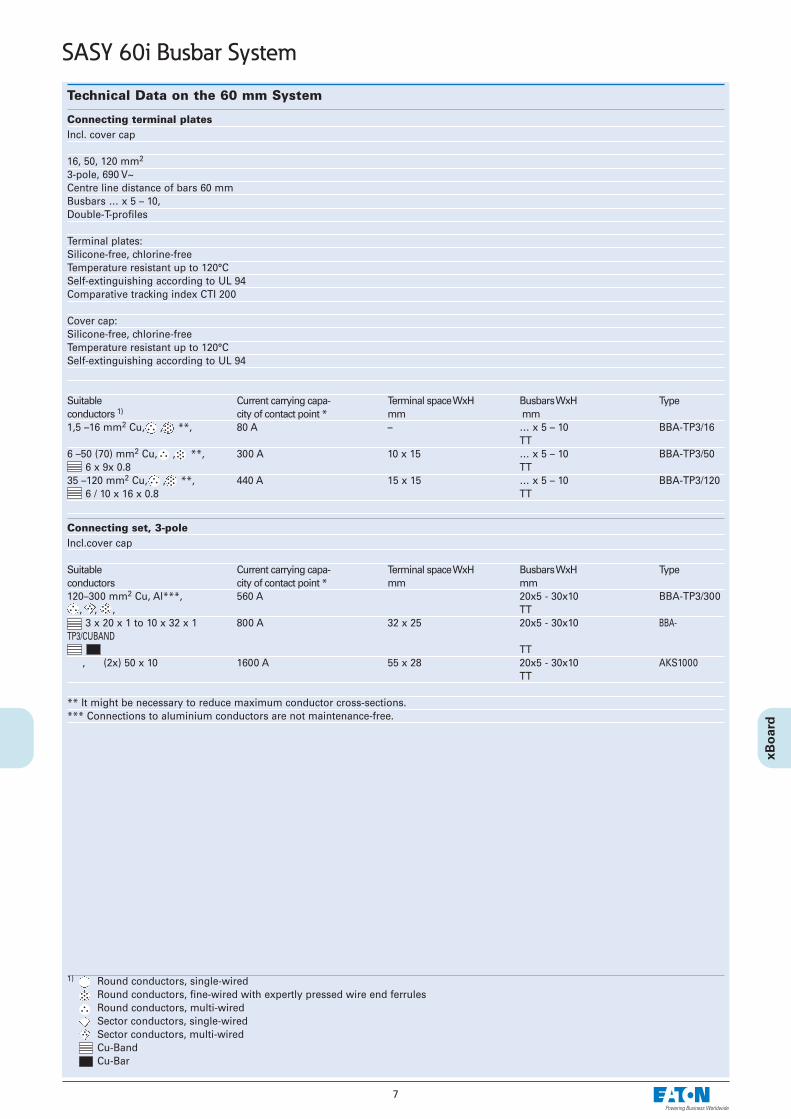
Connecting terminal plates Incl. cover cap
16, 50, 120 mm2
3-pole, 690 V~Centre line distance of bars 60 mmBusbars … x 5 – 10,Double-T-profiles
Terminal plates:Silicone-free, chlorine-freeTemperature resistant up to 120°CSelf-extinguishing according to UL 94Comparative tracking index CTI 200
Cover cap:Silicone-free, chlorine-free Temperature resistant up to 120°CSelf-extinguishing according to UL 94
Suitable Current carrying capa- Terminal space WxH Busbars WxH Typeconductors 1) city of contact point * mm mm1,5 –16 mm2 Cu, , **, 80 A – … x 5 – 10 BBA-TP3/16
TT6 –50 (70) mm2 Cu, , **, 300 A 10 x 15 … x 5 – 10 BBA-TP3/50
6 x 9x 0.8 TT35 –120 mm2 Cu, , **, 440 A 15 x 15 … x 5 – 10 BBA-TP3/120
6 / 10 x 16 x 0.8 TT
Connecting set, 3-poleIncl.cover cap
Suitable Current carrying capa- Terminal space WxH Busbars WxH Typeconductors city of contact point * mm mm120–300 mm2 Cu, Al***, 560 A 20x5 - 30x10 BBA-TP3/300
, , , TT3 x 20 x 1 to 10 x 32 x 1 800 A 32 x 25 20x5 - 30x10 BBA-
TP3/CUBANDTT
, (2x) 50 x 10 1600 A 55 x 28 20x5 - 30x10 AKS1000TT
** It might be necessary to reduce maximum conductor cross-sections.*** Connections to aluminium conductors are not maintenance-free.
1) Round conductors, single-wiredRound conductors, fine-wired with expertly pressed wire end ferrulesRound conductors, multi-wired Sector conductors, single-wired Sector conductors, multi-wired Cu-BandCu-Bar
8
SASY 60i Busbar System
Technical Data on the 60 mm System
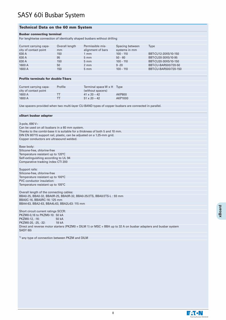
Busbar connecting terminalFor lenghtwise connection of identically shaped busbars without drilling
Current carrying capa- Overall length Permissible mis- Spacing between Typecity of contact point mm alignment of bars systems in mm630 A 150 1 mm 100 - 110 BBT-CU12-20X5/10-150630 A 95 5 mm 50 - 60 BBT-CU20-30X5/10-95630 A 150 5 mm 100 - 110 BBT-CU20-30X5/10-1501600 A 50 2 mm 9 -20 BBT-CU-BAR500/720-501600 A 150 5 mm 100 - 110 BBT-CU-BAR500/720-150
Profile terminals for double-T-bars
Current carrying capa- Profile Terminal space W x H Typecity of contact point (without spacers)1600 A TT 41 x 20 – 42 AKP8001600 A TT 51 x 20 – 42 AKP1000
Use spacers provided when two multi-layer CU-BAND types of copper busbars are connected in parallel.
xStart busbar adapter
3-pole, 690 V~Can be used on all busbars in a 60 mm system.Thanks to the combi-base it is suitable for a thickness of both 5 and 10 mm. DIN EN 60715 support rail, plastic, can be adjusted on a 1.25-mm grid.Copper conductors are ultrasound welded.
Base body:Silicone-free, chlorine-free Temperature resistant up to 120°CSelf-extinguishing according to UL 94Comparative tracking index CTI 200
Support rails:Silicone-free, chlorine-free Temperature resistant up to 100°CPVC conductor insulation: Temperature resistant up to 105°C
Overall length of the connecting cables:BBA0-25, BBA0-32, BBA0R-25, BBA0R-32, BBA0-25/2TS, BBA0/2TS-L : 93 mmBBA0C-16, BBA0RC-16: 125 mmBBA4-63, BBA2-63, BBA4L-63, BBA2L-63: 115 mm
Short circuit current ratings SCCR:PKZM0-0,16 to PKZM0-10: 50 kAPKZM0-12, -16: 50 kAPKZM0-20, -25, -32: 18 kADirect and reverse motor starters (PKZM0 + DILM 1) or MSC + BBA up to 32 A on busbar adapters and busbar system SASY 60i
1) any type of connection between PKZM and DILM
9
SASY 60i Busbar System
Technical Data on the 60 mm System
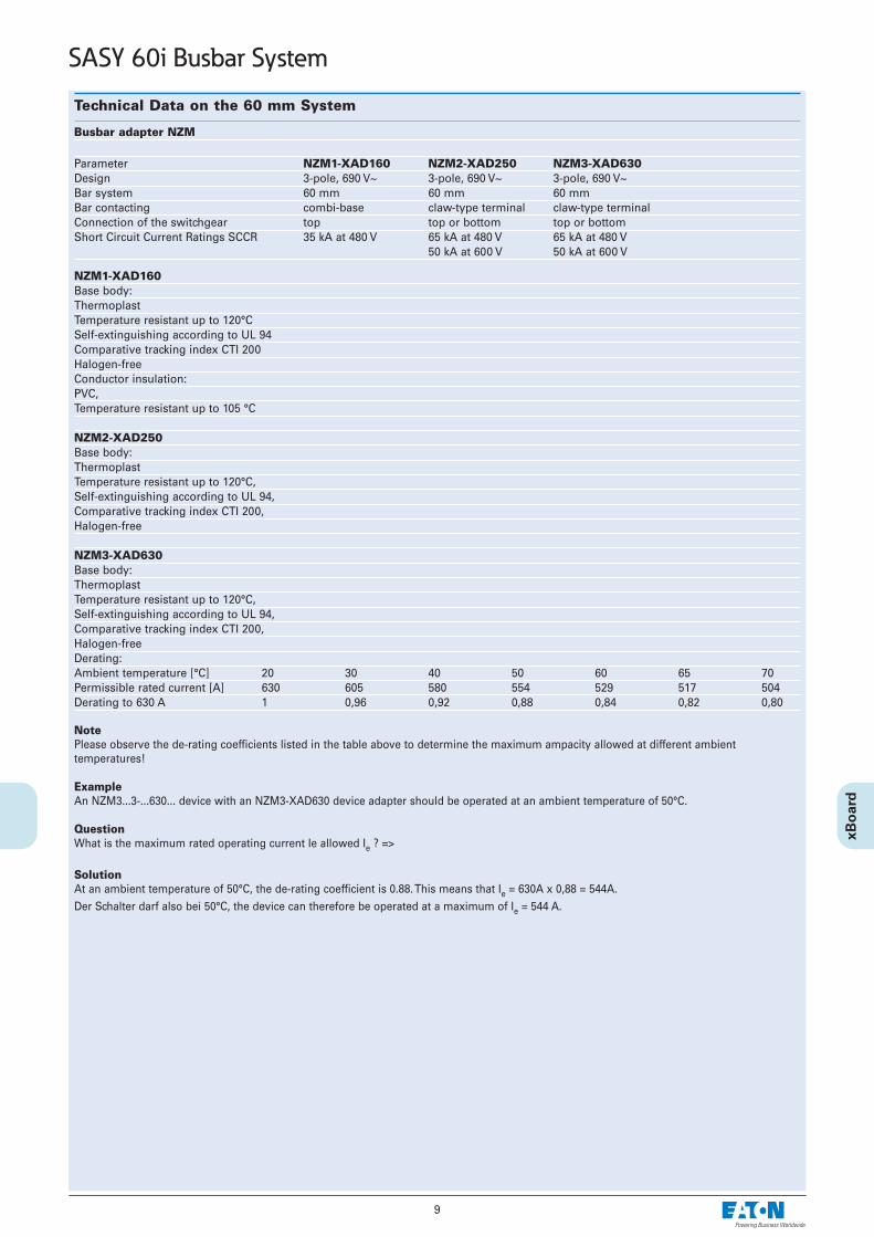
Busbar adapter NZM
Parameter NZM1-XAD160 NZM2-XAD250 NZM3-XAD630Design 3-pole, 690 V~ 3-pole, 690 V~ 3-pole, 690 V~Bar system 60 mm 60 mm 60 mmBar contacting combi-base claw-type terminal claw-type terminalConnection of the switchgear top top or bottom top or bottomShort Circuit Current Ratings SCCR 35 kA at 480 V 65 kA at 480 V 65 kA at 480 V
50 kA at 600 V 50 kA at 600 V
NZM1-XAD160Base body:ThermoplastTemperature resistant up to 120°CSelf-extinguishing according to UL 94Comparative tracking index CTI 200Halogen-freeConductor insulation:PVC,Temperature resistant up to 105 °C
NZM2-XAD250Base body:ThermoplastTemperature resistant up to 120°C,Self-extinguishing according to UL 94,Comparative tracking index CTI 200,Halogen-free
NZM3-XAD630Base body:ThermoplastTemperature resistant up to 120°C,Self-extinguishing according to UL 94,Comparative tracking index CTI 200,Halogen-free Derating:Ambient temperature [°C] 20 30 40 50 60 65 70Permissible rated current [A] 630 605 580 554 529 517 504Derating to 630 A 1 0,96 0,92 0,88 0,84 0,82 0,80
NotePlease observe the de-rating coefficients listed in the table above to determine the maximum ampacity allowed at different ambient temperatures!
ExampleAn NZM3...3-...630... device with an NZM3-XAD630 device adapter should be operated at an ambient temperature of 50°C.
QuestionWhat is the maximum rated operating current Ie allowed Ie ? =>
SolutionAt an ambient temperature of 50°C, the de-rating coefficient is 0.88. This means that Ie = 630A x 0,88 = 544A. Der Schalter darf also bei 50°C, the device can therefore be operated at a maximum of Ie = 544 A.

10
SASY 60i Busbar System
D-Type Slide Fuse-Base
D02-SO/63/3-R-27 DII-SO/25/3-R(-PS) DIII-SO/63/3-R(-PS)Z-D02/R/3...
ElectricalNumber of poles 3 3 3Rated operational voltage Ue 400 V AC 500 V AC 690 V ACRated frequency 40-60 Hz 40-60 Hz 40-60 HzRated operational current Ie 63 A 25 A 63 AConv. thermal current with fuse-links Ith 63 A 25 A 63 ARated duty uninterrupted duty uninterrupted duty uninterrupted dutyRated conditional short-circuit current 50 kAr.m.s. 50 kAr.m.s. 50 kAr.m.s.Overvoltage category IV III IIIRated impulse withstand voltage Uimp 6 kV 4 kV 4 kVPower loss per current path 0.5 W 0.4 W 3.34 WPower loss of base without fuse-links 1.5 W 1.2 W 10 WMax. permissible power loss of fuse-links 5.5 W 4 W 7 W
MechanicalDevice height 201 mm 200 mm 200 mmWidth 27 mm 45 mm 54 mmWeight 150 g 140 g 150 gMounting onto busbars, without drilling or screwing 12x5/10 12x5/10 12x5/10
15x5/1020x5/10 20x5/10 20x5/1025x5/10 25x5/10 25x5/1030x5/10 30x5/10 30x5/10
Degree of protection while operating IP20 IP20 IP20Terminals Lift terminals Lift terminals Lift terminalsTerminal capacity 1.5-35 mm2 1.5-25 mm2 1.5-25 mm2
Tightening torque of terminal screws 3-4 Nm 2.6 Nm 2.6 NmElectrical thread type E18 E27 E33Ambient temperature range -25 to +55°C -25 to +55°C *) -25 to +55°C *)
*) (35°C normal temperature, at 55°C with reduced operating current)Pollution degree 3 3 3Climatic resistance: moist heat constant acc. to IEC 60068-2-78, cyclical acc. to IEC 60068-2-30
Busbar-Slide Switch Disconnector with Fuses D02-S/63/3-RS• Design according to IEC/EN 60947-3• Vertical and horizontal mounting possible• Supplied empty, without screw caps• Current coding by means of cartridge-ring adapter insert• Suitable for fuse-links
D01: 2, 4, 6, 10, 16 A in combination with cartridge-ring adapter insertsZ-D02-D01/PE-.. and adapter spring Z-D02/SIKA-HF
D02: 20, 25, 35, 50, 63 A• Can be sealed with lead
Technical Data
ElectricalNumber of poles 3PRated operational voltage Ue
AC 400 V / 40-60 HzRated operational current Ie 63 AConv. thermal current
with fuse-links Ith 63 ARated duty Uninterrupted dutyRated conditional short-circuit current 50 kAr.m.s.Utilization category AC 23 BOvervoltage category IIIRated impulse withstand voltage Uimp 8 kVPower loss per current path 0.5 W with IePower loss per current path
with fuse-link 7.5 W with IeMax. permissible power loss
of fuse-links 5.5 W
MechanicalDevice height 212 mmWidth 36 mmWeight 260 gMounting onto busbars, 20x5/10 mm
without drilling or screwing 30x5/10 mmDegree of protection while operating IP30Terminals Lift terminalsTerminal capacity 1.5-25 mm2 CuTightening torqueof terminal screws max. 2.6 NmElectrical thread type E18Temperature range -25 to +55°CPollution degree 3
Connection diagram
Technical Data
• Design according to IEC/EN 60269-1, VDE 0636 Part 301• Vertical and horizontal mounting possible• Delivered empty, without screw caps
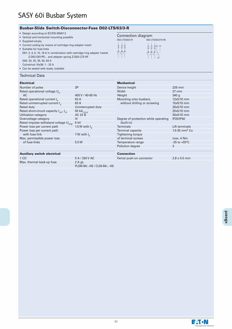
Busbar-Slide Switch-Disconnector-Fuse D02-LTS/63/3-R• Design according to IEC/EN 60947-3• Vertical and horizontal mounting possible• Supplied empty• Current coding by means of cartridge-ring adapter insert• Suitable for fuse-links
D01: 2, 4, 6, 10, 16 A in combination with cartridge-ring adapter insertsZ-D02-D01/PE-.. and adapter spring Z-D02-LTS-HF
D02: 20, 25, 35, 50, 63 ACylindrical 10x38: 1 - 32 A
• Can be sealed with leads, lockable
Technical Data
ElectricalNumber of poles 3PRated operational voltage Ue
AC 400 V / 40-60 HzRated operational current Ie 63 ARated uninterrupted current Iu 63 ARated duty Uninterrupted dutyRated short-circuit capacity Icm, Icn 50 kAr.m.s.Utilization category AC 22 BOvervoltage category IVRated impulse withstand voltage Uimp 6 kVPower loss per current path 1.5 W with IePower loss per current path
with fuse-link 7 W with IeMax. permissible power loss
of fuse-links 5.5 W
MechanicalDevice height 226 mmWidth 27 mmWeight 340 gMounting onto busbars, 12x5/10 mm
without drilling or screwing 15x5/10 mm20x5/10 mm25x5/10 mm30x5/10 mm
Degree of protection while operating IP20/IP40(built-in)
Terminals Lift terminalsTerminal capacity 1.5-35 mm2 CuTightening torqueof terminal screws max. 4 NmTemperature range -25 to +55°CPollution degree 3
Connection diagram
11
SASY 60i Busbar System
D02-LTS/63/3-R D02-LTS/63/3-R-HK
Auxiliary switch electrical1 CO 5 A / 250 V ACMax. thermal back-up fuse 2 A gL
PLSM-B4/..-HS / CLS6-B4/...-HS
Connection Femal push-on connector 2.8 x 0.5 mm
12
SASY 60i Busbar System
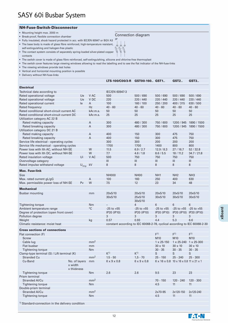
NH-Fuse-Switch-Disconnector• Mounting height max. 2000 m• Break-proof, flexible connection chamber• Fully insulated, shock hazard protected in acc. with IEC/EN 60947 or BGV A3• The base body is made of glass fibre reinforced, high-temperature resistant,
self-extinguishing and halogen-free plastic• The contact system consists of separately spring-loaded silver-plated copper
contacts• The switch cover is made of glass fibre reinforced, self-extinguishing, silicone and chlorine-free thermoplast• The switch cover features large viewing windows allowing to read the labelling and to see the flat indicator of the NH-fuse-links• The viewing windows provide test holes • Vertical and horizontal mounting position is possible • Delivery without NH-fuse-links
LTS-100/C00/3-R GST00-160.. GST1.. GST2.. GST3..
ElectricalTechnical data according to IEC/EN 60947-3Rated operational voltage Ue V AC 500 500 / 690 500 / 690 500 / 690 500 / 690Rated operational voltage Ue V DC 220 220 / 440 220 / 440 220 / 440 220 / 440Rated operational current Ie A 100 160 / 100 250 / 200 400 / 315 630 / 500Rated frequency Hz 40 - 60 40 - 60 40 - 60 40 - 60 40 - 60Rated conditional short-circuit current AC kAr.m.s. 50 50 50 50 50Rated conditional short-circuit current DC kAr.m.s. 25 25 25 25 25Utilization category AC 22 B
Rated making capacity A 300 480 / 300 750 / 600 1200 / 945 1890 / 1500Rated breaking capacity A 300 480 / 300 750 / 600 1200 / 945 1890 / 1500
Utilization category DC 21 B Rated making capacity A 400 150 300 475 750Rated breaking capacity A 400 150 300 475 750
Service life electrical - operating cycles 300 300 200 200 200Service life mechanical - operating cycles 1700 1700 1400 800 800Power loss with Ith AC, without NH-SE W 11.5 6.9 / 2.7 12.9 / 8.3 27 / 16.7 52 / 32.8Power loss with Ith DC, without NH-SE W 7.7 4.6 / 1.8 8.6 / 5.5 18 / 11.2 34.7 / 21.8Rated insulation voltage Ui V AC 500 750 750 750 750Overvoltage category III III III III IIIRated impulse withstand voltage Uimp kV 8 8 8 8 8
Max. Fuse-linkSize NH000 NH00 NH1 NH2 NH3Max. rated current gL/gG A 100 160 250 400 630Max. permissible power loss of NH-SE Pv W 7.5 12 23 34 48
MechanicalBusbar mounting mm 20x5/10 20x5/10 20x5/10 20x5/10 20x5/10
30x5/10 25x5/10 30x5/10 30x5/10 30x5/1030x5/10
Tightening torque Nm – 4 6 6 6Ambient temperature range °C -25 to +55 -25 to +55 -25 to +55 -25 to +55 -25 to +55Degree of protection (open front cover) IP20 (IP10) IP20 (IP10) IP20 (IP10) IP20 (IP10) IP20 (IP10)Pollution degree 3 3 3 3 3Weight kg 0.57 0.93 4.4 5.3 6.6Climatic resistance: moist heat constant according to IEC 60068-2-78, cyclical according to IEC 60068-2-30
Cross sections of connectionsFlat connection (F) F1) F1) F1)
Screw M10 M10 M10Cable lug mm2 1 x 25-150 1 x 25-240 1 x 25-300Flat busbar mm 30 x 10 30 x 10 30 x 10Tightening torque Nm 30 - 35 30 - 35 30 - 35
Clamp-type terminal (S) / Lift terminal (K) K1) K1) S S SStranded Cu mm2 1.5 - 50 1,5 - 70 25 - 150 25 - 240 25 - 300Cu-Band No. of layers mm 6 x 9 x 0.8 6 x 9 x 0.8 6 x 16 x 0.8 10 x 16 x 0.8 11 x 21 x 1
x widthx thickness
Tightening torque Nm 2.6 2.6 9.5 23 23Prism terminal
Stranded Al/Cu mm2 70 - 150 120 - 240 120 - 300Tightening torque Nm 4.5 11 11
Double-prism terminal Stranded Al/Cu mm2 2x70-95 2x120-150 2x120-240Tightening torque Nm 4.5 11 11
1) Standard-connection in the delivery condition
Connection diagram3P
13
SASY 60i Busbar System
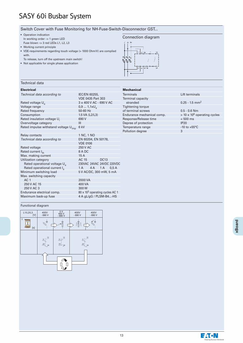
Switch Cover with Fuse Monitoring for NH-Fuse-Switch-Disconnector GST...• Operation indication
In working order –> 1 green LED Fuse blown –> 3 red LEDs L1, L2, L3
• Working current principle• VDE-requirements regarding touch voltage (> 1000 Ohm/V) are complied
with.To release, turn off the upstream main switch!
• Not applicable for single phase application
Connection diagram
Technical data
Electrical Technical data according to IEC/EN 60255,
VDE 0435 Part 303Rated voltage Ue 3 x 400 V AC - 690 V ACVoltage range 0,9 ... 1,1xUeRated frequency 50-60 HzConsumption 1.5 VA (L2/L3)Rated insulation voltage Ui 690 VOvervoltage category IIIRated impulse withstand voltage Uimp 6 kV
Relay contacts 1 NC, 1 NOTechnical data according to EN 60204, EN 50178,
VDE 0106Rated voltage 250 V ACRated current Ith 8 A DCMax. making current 15 AUtilization category AC 15 DC13
Rated operational voltage Ue 230VAC 24VAC 24VDC 220VDCRated operational current Ie 1 A 4 A 1 A 0,5 A
Minimum switching load 5 V AC/DC, 300 mW, 5 mAMax. switching capacity
AC 1 2000 VA250 V AC 15 400 VA250 V AC 3 300 W
Endurance electrical comp. 80 x 103 operating cycles AC 1Maximum back-up fuse 4 A gL/gG / PLSM-B4...-HS
MechanicalTerminals Lift terminalsTerminal capacity
stranded 0.25 - 1.5 mm2
Tightening torqueof terminal screws 0.5 - 0.6 NmEndurance mechanical comp. > 10 x 106 operating cyclesResponse/Release time < 500 msDepree of protection IP20Temperature range -10 to +55°CPollution degree 3
Functional diagram
14
SASY 60i Busbar System
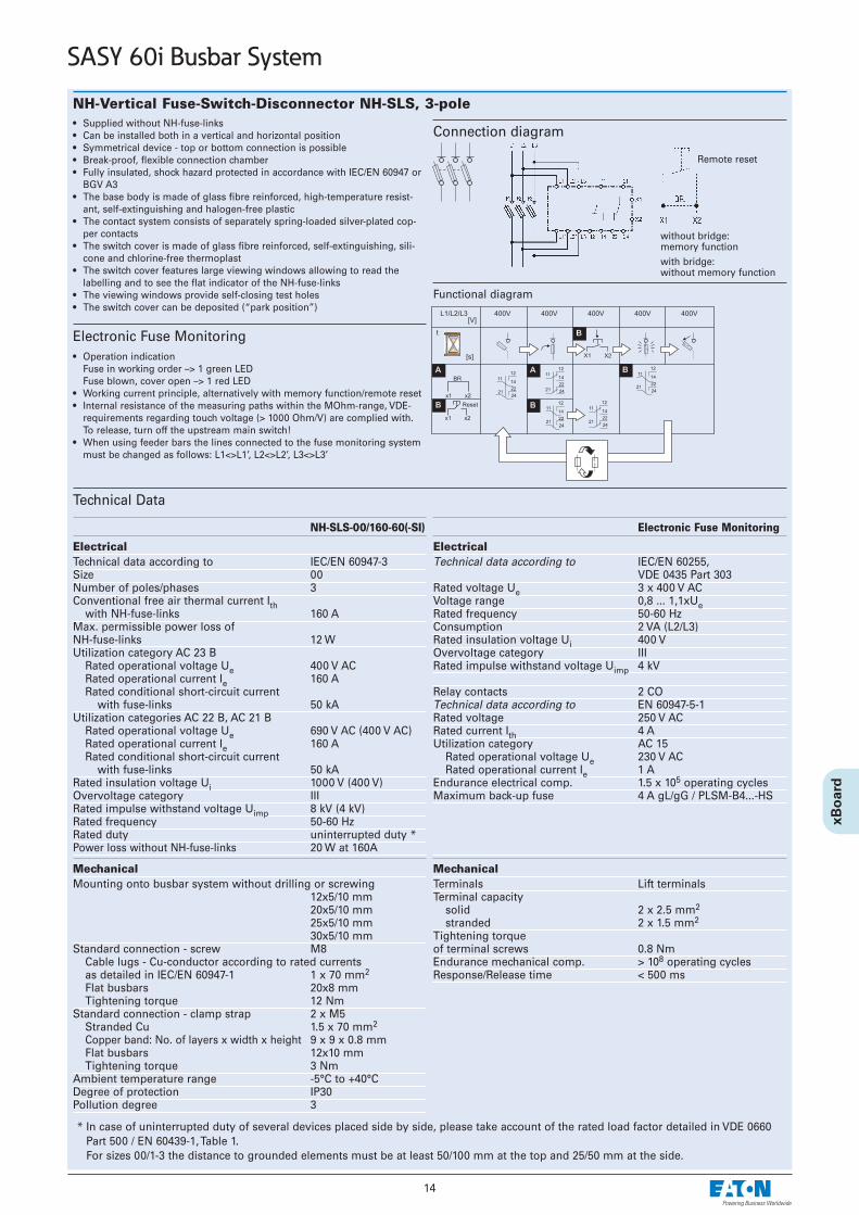
NH-Vertical Fuse-Switch-Disconnector NH-SLS, 3-pole• Supplied without NH-fuse-links • Can be installed both in a vertical and horizontal position • Symmetrical device - top or bottom connection is possible• Break-proof, flexible connection chamber• Fully insulated, shock hazard protected in accordance with IEC/EN 60947 or
BGV A3• The base body is made of glass fibre reinforced, high-temperature resist-
ant, self-extinguishing and halogen-free plastic • The contact system consists of separately spring-loaded silver-plated cop-
per contacts• The switch cover is made of glass fibre reinforced, self-extinguishing, sili-
cone and chlorine-free thermoplast • The switch cover features large viewing windows allowing to read the
labelling and to see the flat indicator of the NH-fuse-links • The viewing windows provide self-closing test holes • The switch cover can be deposited (“park position”)
Technical Data
NH-SLS-00/160-60(-SI)
Electrical Technical data according to IEC/EN 60947-3Size 00Number of poles/phases 3Conventional free air thermal current Ith
with NH-fuse-links 160 AMax. permissible power loss ofNH-fuse-links 12 WUtilization category AC 23 B
Rated operational voltage Ue 400 V AC Rated operational current Ie 160 ARated conditional short-circuit current
with fuse-links 50 kAUtilization categories AC 22 B, AC 21 B
Rated operational voltage Ue 690 V AC (400 V AC)Rated operational current Ie 160 ARated conditional short-circuit current
with fuse-links 50 kARated insulation voltage Ui 1000 V (400 V)Overvoltage category IIIRated impulse withstand voltage Uimp 8 kV (4 kV)Rated frequency 50-60 HzRated duty uninterrupted duty *Power loss without NH-fuse-links 20 W at 160A
Mechanical Mounting onto busbar system without drilling or screwing
12x5/10 mm20x5/10 mm25x5/10 mm30x5/10 mm
Standard connection - screw M8Cable lugs - Cu-conductor according to rated currentsas detailed in IEC/EN 60947-1 1 x 70 mm2
Flat busbars 20x8 mmTightening torque 12 Nm
Standard connection - clamp strap 2 x M5Stranded Cu 1.5 x 70 mm2
Copper band: No. of layers x width x height 9 x 9 x 0.8 mmFlat busbars 12x10 mmTightening torque 3 Nm
Ambient temperature range -5°C to +40°CDegree of protection IP30Pollution degree 3
Connection diagram
* In case of uninterrupted duty of several devices placed side by side, please take account of the rated load factor detailed in VDE 0660Part 500 / EN 60439-1, Table 1. For sizes 00/1-3 the distance to grounded elements must be at least 50/100 mm at the top and 25/50 mm at the side.
Remote reset
without bridge: memory functionwith bridge:without memory function
Electronic Fuse Monitoring• Operation indication
Fuse in working order –> 1 green LED Fuse blown, cover open –> 1 red LED
• Working current principle, alternatively with memory function/remote reset• Internal resistance of the measuring paths within the MOhm-range, VDE-
requirements regarding touch voltage (> 1000 Ohm/V) are complied with. To release, turn off the upstream main switch!
• When using feeder bars the lines connected to the fuse monitoring systemmust be changed as follows: L1<>L1’, L2<>L2’, L3<>L3’
Functional diagram
Electronic Fuse Monitoring
Electrical Technical data according to IEC/EN 60255,
VDE 0435 Part 303Rated voltage Ue 3 x 400 V ACVoltage range 0,8 ... 1,1xUeRated frequency 50-60 HzConsumption 2 VA (L2/L3)Rated insulation voltage Ui 400 VOvervoltage category IIIRated impulse withstand voltage Uimp 4 kV
Relay contacts 2 COTechnical data according to EN 60947-5-1Rated voltage 250 V ACRated current Ith 4 AUtilization category AC 15
Rated operational voltage Ue 230 V ACRated operational current Ie 1 A
Endurance electrical comp. 1.5 x 10⁵ operating cyclesMaximum back-up fuse 4 A gL/gG / PLSM-B4...-HS
MechanicalTerminals Lift terminalsTerminal capacity
solid 2 x 2.5 mm2
stranded 2 x 1.5 mm2
Tightening torqueof terminal screws 0.8 NmEndurance mechanical comp. > 108 operating cyclesResponse/Release time < 500 ms
15
SASY 60i Busbar System
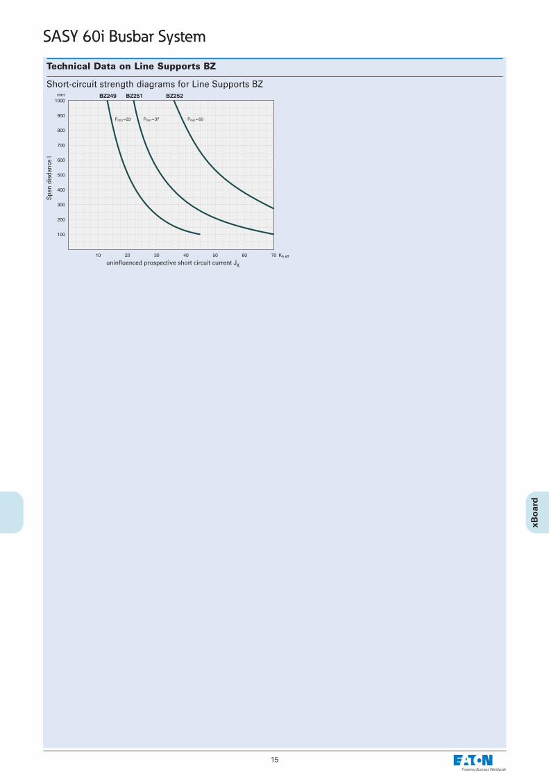
Technical Data on Line Supports BZ
Short-circuit strength diagrams for Line Supports BZ
Spa
n di
sdan
ce l
uninfluenced prospective short circuit current JK

16
SASY 60i Busbar System
Dimensions
BBS-3/FL
ES-BBS-3/FL
BBS-3/FL-NA
BBS-2/FL
17
SASY 60i Busbar System
Dimensions
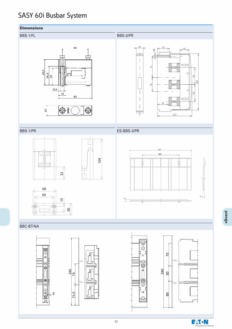
BBS-1/FL
BBS-1/PR
BBS-3/PR
ES-BBS-3/PR
BBC-BT-NA
18
SASY 60i Busbar System
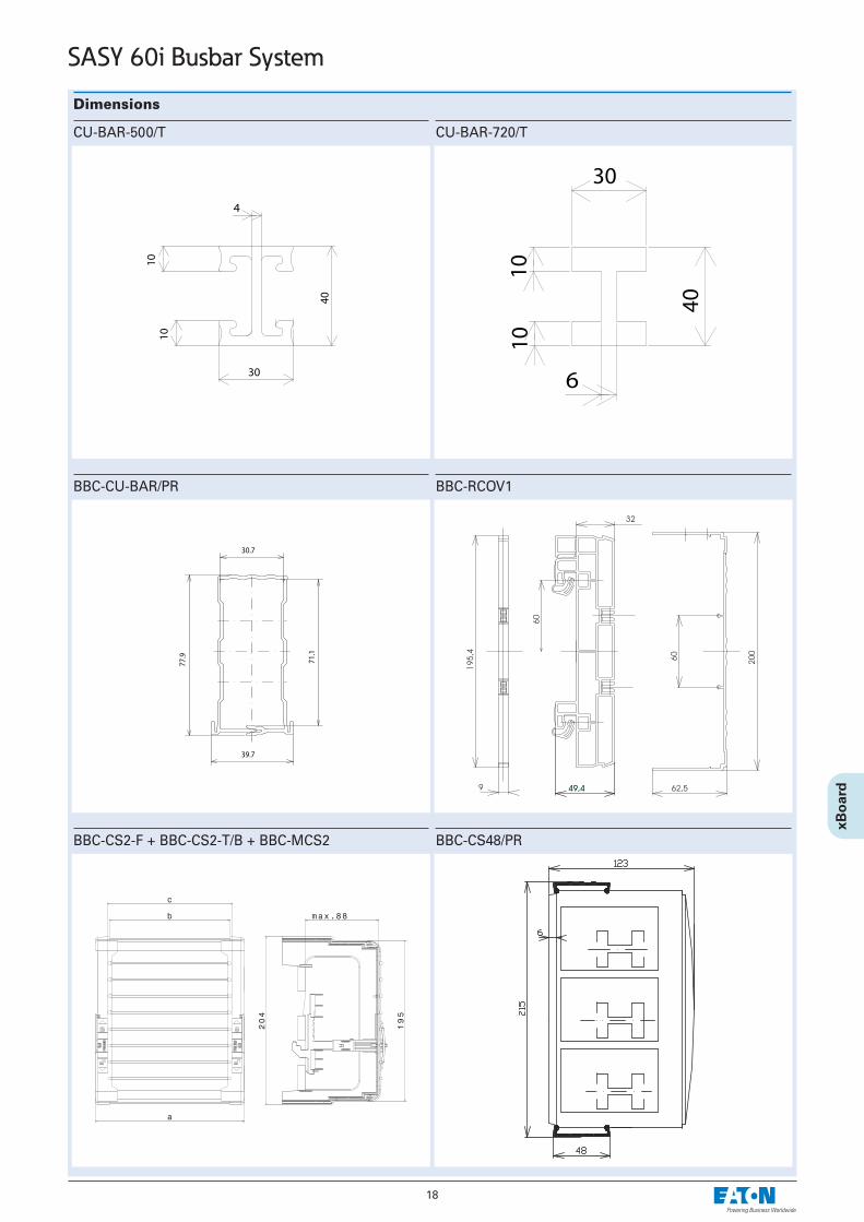
Dimensions
CU-BAR-500/T
BBC-CU-BAR/PR
CU-BAR-720/T
BBC-RCOV1
BBC-CS2-F + BBC-CS2-T/B + BBC-MCS2 BBC-CS48/PR
19
SASY 60i Busbar System
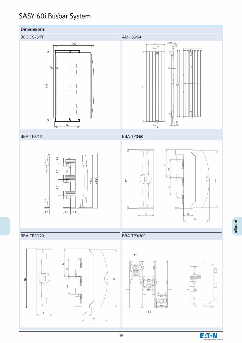
Dimensions
BBC-CS76/PR
BBA-TP3/16
AM-195/54
BBA-TP3/50
BBA-TP3/120 BBA-TP3/300
20
SASY 60i Busbar System
Dimensions
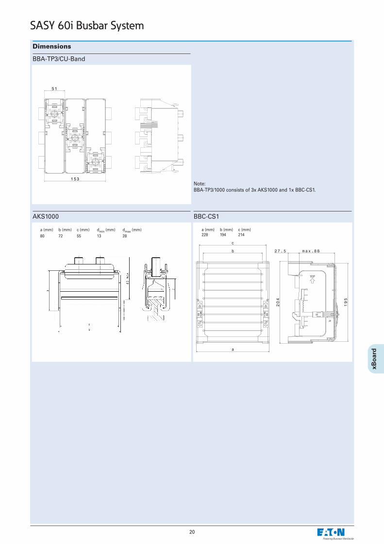
BBA-TP3/CU-Band
AKS1000 BBC-CS1
a (mm) b (mm) c (mm)228 194 214
a (mm) b (mm) c (mm) dmin (mm) dmax (mm)80 72 55 13 28
Note:BBA-TP3/1000 consists of 3x AKS1000 and 1x BBC-CS1.
21
SASY 60i Busbar System
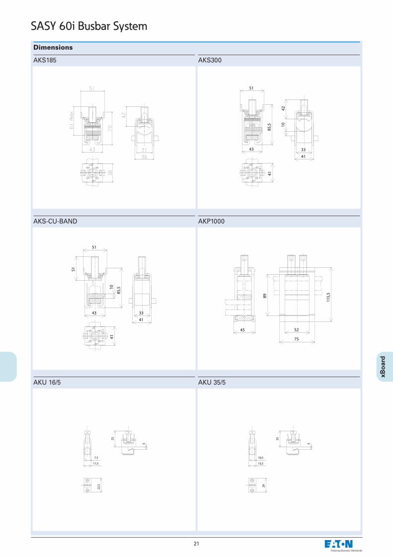
Dimensions
AKS185
AKS-CU-BAND
AKS300
AKP1000
AKU 16/5 AKU 35/5
22
SASY 60i Busbar System
Dimensions
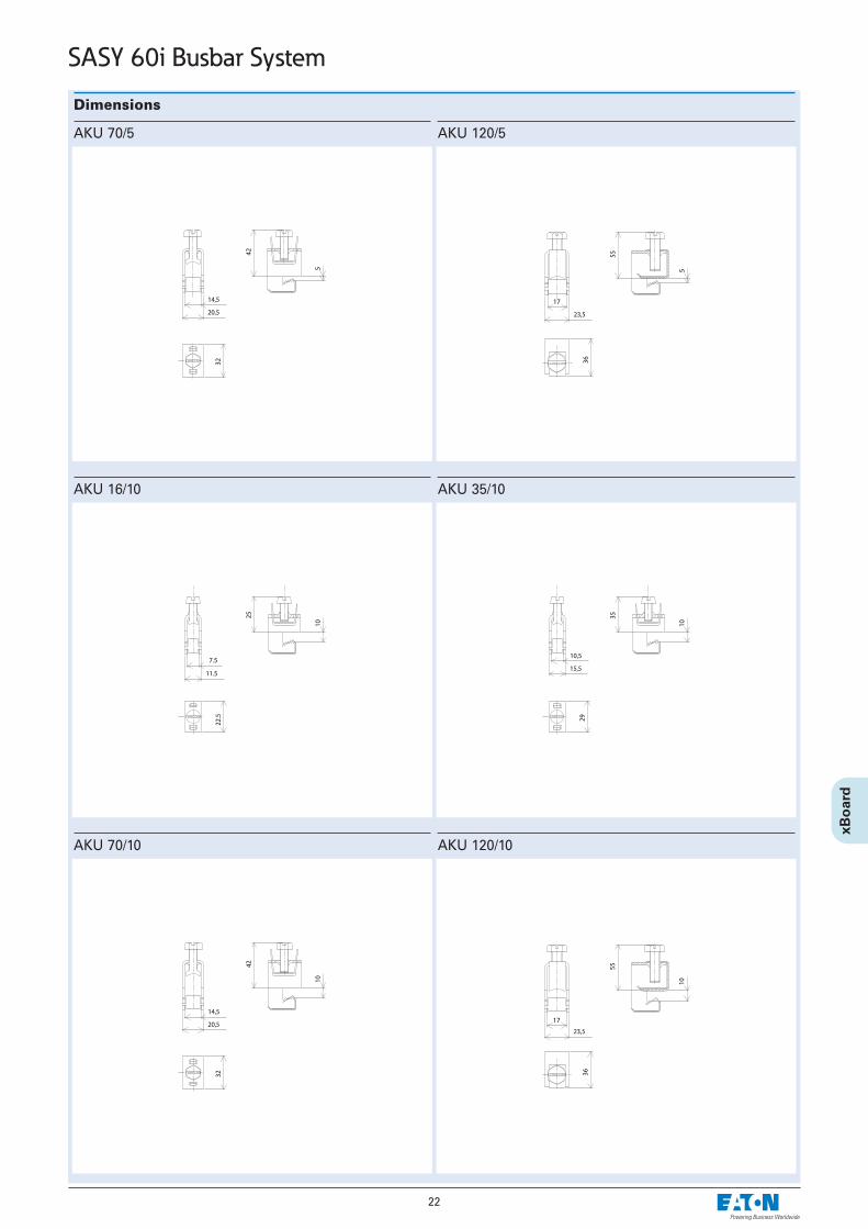
AKU 70/5
AKU 16/10
AKU 120/5
AKU 35/10
AKU 70/10 AKU 120/10

23
SASY 60i Busbar System
Dimensions
BBT-CU20-30X5/10-95
BBT-CU-BAR500/720-50
BBT-CU20-30X5/10-150
BBT-CU-BAR500/720-150
BBT-CU12-20x5/10-150

24
SASY 60i Busbar System
Dimensions
NZM1-XAD160
NZM2-XAD250
25
SASY 60i Busbar System
Dimensions
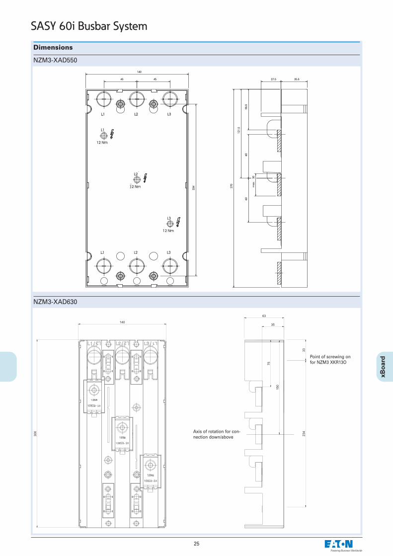
NZM3-XAD550
NZM3-XAD630
Axis of rotation for con-nection down/above
Point of screwing onfor NZM3 XKR13O
Dimensions
26
SASY 60i Busbar System
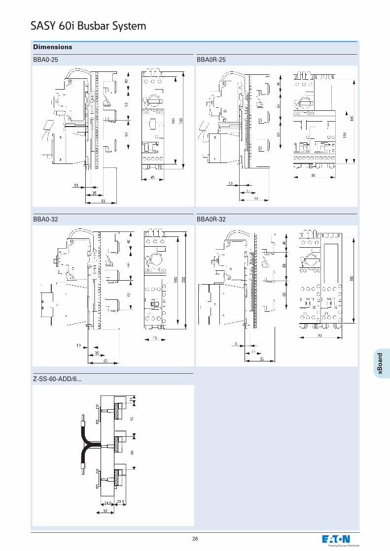
BBA0R-25
BBA0-32
BBA0-25
BBA0R-32
Z-SS-60-ADD/6...
Dimensions
27
SASY 60i Busbar System
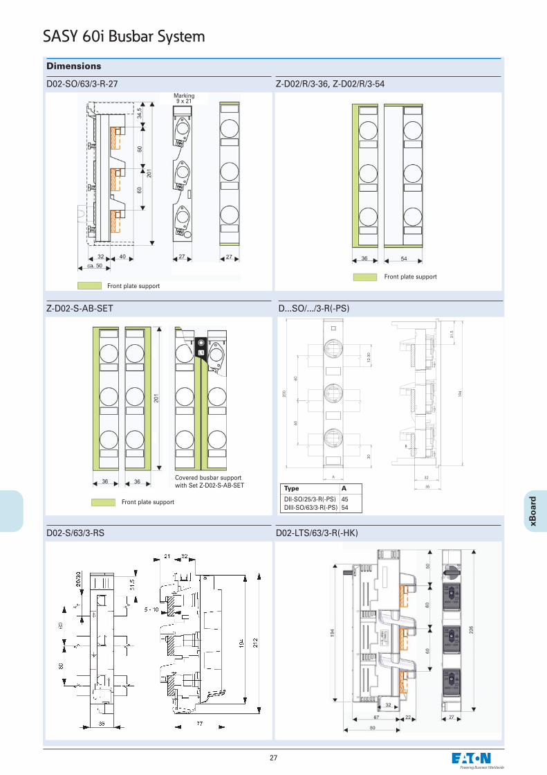
Z-D02/R/3-36, Z-D02/R/3-54D02-SO/63/3-R-27
Z-D02-S-AB-SET
Front plate supportFront plate support
Marking9 x 21
Front plate support
Covered busbar supportwith Set Z-D02-S-AB-SET
D...SO/.../3-R(-PS)
Type A
DII-SO/25/3-R(-PS) 45DIII-SO/63/3-R(-PS) 54
D02-S/63/3-RS D02-LTS/63/3-R(-HK)
28
SASY 60i Busbar System
Dimensions
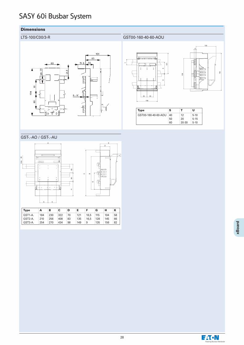
GST00-160-40-60-AOU
GST-.-AO / GST-.-AU
Type S T U
GST00-160-40-60-AOU 40 12 5-1050 20 5-1560 20-30 5-10
Type A B C D E F G H K
GST1-A. 184 230 322 70 121 16,5 115 104 58GST2-A. 210 256 408 83 135 16,5 128 145 66GST3-A. 254 270 434 98 149 9 135 156 82
LTS-100/C00/3-R
29
SASY 60i Busbar System
Dimensions
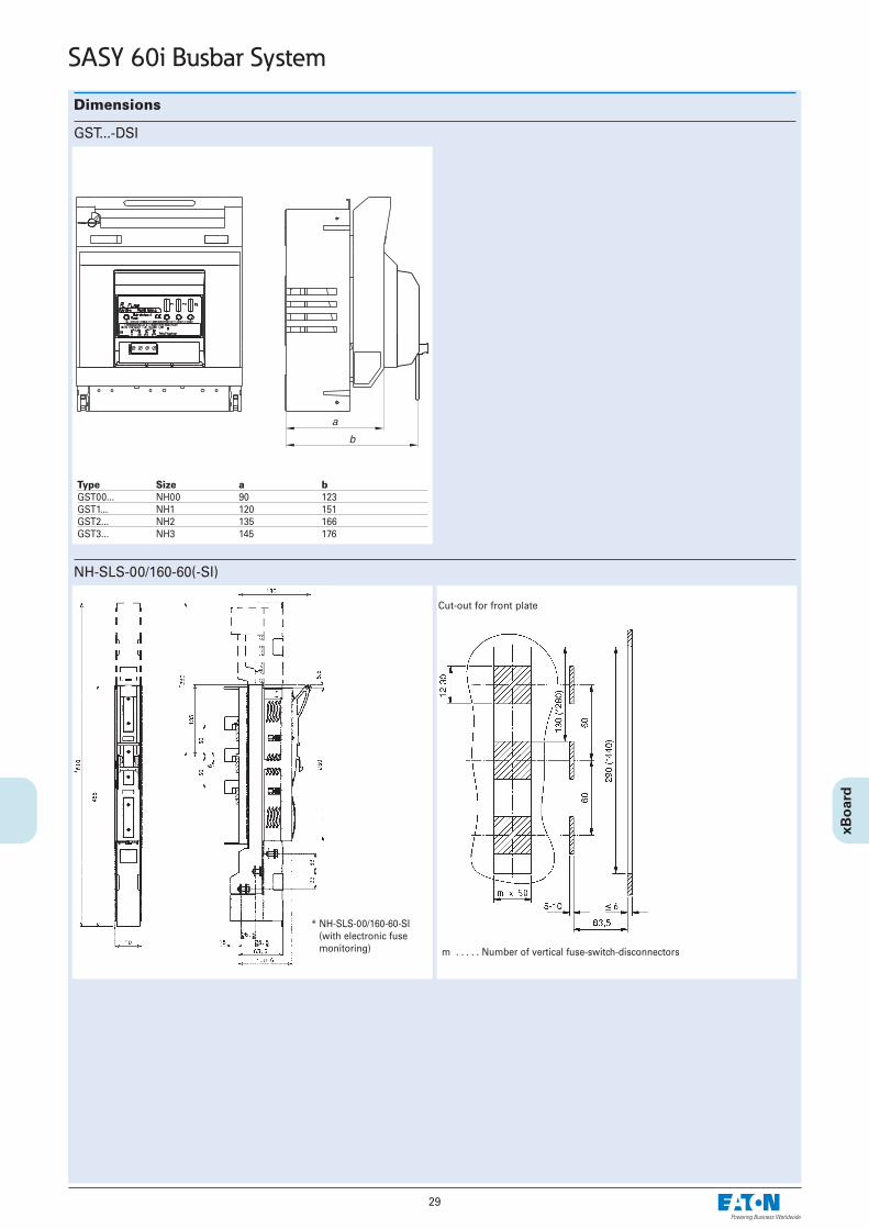
NH-SLS-00/160-60(-SI)
m . . . . . Number of vertical fuse-switch-disconnectors
* NH-SLS-00/160-60-SI (with electronic fusemonitoring)
Cut-out for front plate
GST...-DSI
Type Size a bGST00... NH00 90 123GST1... NH1 120 151GST2... NH2 135 166GST3... NH3 145 176