Embed Size (px)
Citation preview

1
© Dr Z SUN, University of Surrey1Satellite Networking
Satellite Networkingas a component of Satellite Communications B (EEM.scmB)
Dr Zhili SUN Centre for Communication Systems Research
School of Electronic Engineering, Information Technology & MathematicsUniversity of Surrey
GuildfordSurrey
GU2 7XHTel: 01483 68 9493Fax: 01483 68 6011
Email: [email protected]
Satellite Networkingas a component of Satellite Communications B (EEM.scmB)

2
© Dr Z SUN, University of Surrey2Satellite Networking
Contents
� Network Protocols basics and reference models� Satellite networks and network services� PDH and SDH transmissions technology� SDH - Intelsat scenarios� ISDN� ATM and B-ISDN over satellite� TCP/IP over satellite� IP QoS over satellite

3
© Dr Z SUN, University of Surrey3Satellite Networking
Satellite Networking Review
� Network protocol basics and reference models� Telecommunication Services� Network Description and Architecture� Basic Technical Issues� Digital Transmission (PDH & SDH)� SDH over Satellite - Intelsat scenarios� Satellite system performance related service requirement� Issues on ISDN and B-ISDN� ATM and broadband networks over Satellite� Internet over Satellite and QoS� Standards - ITU-T and ITU-R
Satellite communication is another method of extending the communication networks. The links may be used for telephony, data, facsimile, and video, and also for broadband services and Internet services.
Historically, communication was closely associated with telecommunication networks or telephony networks. All the services and applications were based on the telephony channel of about 4 KHz bandwidth.
Due to the need of data communication, a term, the protocol came into popular use in 1960s. According to the IEEE, the protocol can be defined as: “a formal set of rules and convention governing the format and relative timing of message exchange among two or more communication terminals.”
The protocol provides transport service to the applications of real time and non-real time. The protocol also shields the transmission technologies such copper cable, optical fibre and radio and satellite links from the applications. Different protocol architectures have been developed based on different the transmission technologies to support different types of applications.
When satellite links become a integrated part of the infrastructure, the protocol has significant impact on the performance of the network, quality of service (QoS) provided to the application, and efficiency of making used of the satellite resources.
This lecture discuss all the relevant issues listed in the above slide related to satellite networking and protocols.

4
© Dr Z SUN, University of Surrey4Satellite Networking
Protocol basics

5
© Dr Z SUN, University of Surrey5Satellite Networking
Protocol architecture
� Layers, protocols and interfaces
� Connection-oriented and connectionless services
There are two types of transmission technologies: broadcast and point-to-point transmissions. The scale of physical size of networks can be LAN, MAN and WAN. Satellite networks are inherently and most useful where broadcast property is important. They can also be set up to support point-to-point transmissions in a very wide area.
What is a protocol? It is the rules and convention used in conversation by agreement between communication parties.
Why networking need protocols? It is to reduce design complexity that each layer is designed to offer certain services to high layers, shielding those layer from the details of how the services are actually implemented.
Each layer has an interface with primitive operations which can be used to access to the offered services.
A network architecture is a set of layers and protocols.
A protocol stack is a list of protocols (one protocol per layer)

6
© Dr Z SUN, University of Surrey6Satellite Networking
The ISO reference model
An entity is the active element in each layer.
Peer entities is the entities in the same layer on different machines.
Virtual and actual communication are very useful concepts in protocol design. For example, the HTTP is the protocol used by the WWW. The virtual communication is at the application layer between the local client machine and remote server using the HTTP protocol. The actual communication is in the physical layer with a bit stream.
A network layer such as the ATM provides a connection oriented service where a connection needs to be set up before data exchange and is released after being used. Another such as the IP protocol provides connectionless service where connections are not needed for data exchanges.
Basic protocol functions include segmentation and reassembly, encapsulation, connection control, ordered delivery, flow control, error control, routeing and multiplexing.

7
© Dr Z SUN, University of Surrey7Satellite Networking
Data Transmission in the OSI model
The physical layer (bit stream): it specifies mechanical, electrical and procedure interfaces and the physical transmission medium. In satellite network, radio links are the physical transmission.
Data link layer: it provides a line that appears free of undetected transmission errors to the network layer. Broadcast networks have an additional issues in data link layer, i.e., how to control access to the shared medium. A special sublayer called medium access control (such as Polling, Aloha, FDMA, TDMA, DAMA) deals with this problem.
The network routes packets from source to destination. The functions include network addressing, congestion control, accounting, disassembling and reassembling, coping with heterogeneous network protocols and technologies. In broadcast network, the routing problem is simple. The routing protocol is often thin or even non-existent.
The transport layer provides reliable data delivery service for high layer users. It is the highest layer of the services associated with the provider of communication services. The higher layers are user data services. It has functions of ordered delivery, error control, flow control and congestion control.
The session layer provides the means of for cooperating presentation entities to organise and synchronise their dialogue and to manage the data exchange.
The presentation layers are concerned with data transformation, data formatting and data syntax.
The application layer is the highest layer of the ISO architecture. It provides services to application processes.

8
© Dr Z SUN, University of Surrey8Satellite Networking
Internet - the TCP/IP reference model
The slide shows the initial Internet protocol architecture. It is based on datagram and best effort approach without guarantee quality of service (QoS).
The idea is that the design of a network should only be concerned with transport packets from their source to their destination address. The network is inherently unreliable no matter how you design it. It leaves to users to make it to be reliable if required.
It is claimed to be a successful approach based on 40 years experience of Internet supporting data networks.

9
© Dr Z SUN, University of Surrey9Satellite Networking
The B-ISDN ATM reference model
The slide shows the ATM protocol architecture. It based on connection oriented approach with guarantee quality of service (QoS).
The idea is that the network should be designed very reliable so that users don’t have to worry about if there may be some problems in their data transfer.
It is claimed to be a successful approach based on 100 years experience of telephone networks.

10
© Dr Z SUN, University of Surrey10Satellite Networking
Satellite networks and network services
11
© Dr Z SUN, University of Surrey11Satellite Networking
Custom Designed Networks
� Telecommunication networks� Custom Designed Networks
• Broadcast TV• TV distribution• Small Dish / VSAT type date network
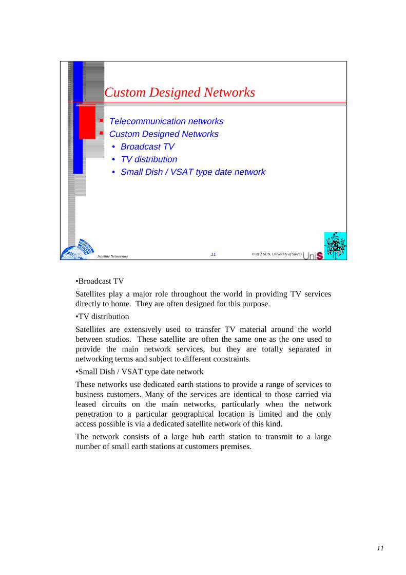
•Broadcast TV
Satellites play a major role throughout the world in providing TV services directly to home. They are often designed for this purpose.
•TV distribution
Satellites are extensively used to transfer TV material around the world between studios. These satellite are often the same one as the one used to provide the main network services, but they are totally separated in networking terms and subject to different constraints.
•Small Dish / VSAT type date network
These networks use dedicated earth stations to provide a range of services to business customers. Many of the services are identical to those carried via leased circuits on the main networks, particularly when the network penetration to a particular geographical location is limited and the only access possible is via a dedicated satellite network of this kind.
The network consists of a large hub earth station to transmit to a large number of small earth stations at customers premises.

12
© Dr Z SUN, University of Surrey12Satellite Networking
Basic Technical Problems
� Propagation Delay� Limited bandwidth� Transmission Errors� Transmission Power
GEO
MEO
LEO
terrestrial
Naturally, there are far greater losses. For LOS microwave we encounter free-space losses possibly as high as 145 dB. In the case of a satellite with a range of 22,300 miles operating on 4.2 GHz, the free-space loss is 196 dB and at 6 GHz, 199 dB. At 14 GHz the loss is about 207 dB. This presents no insurmountable problem from earth to satellite, where comparatively high power transmitters and very high gain antennas may be used. On the contrary, from satellite to earth the link is power-limited for two reasons:
(1) in bands shared with terrestrial services such as the popular 4-GHz band to ensure noninterference with those services and (2) in the satellite itself, which can derive power only from solar cells. It takes a great number of solar cells to produce the RF power necessary; thus the down-link, from satellite to earth, is critical, and received signal levels will be much lower than on comparative radio-links, as low as -150 dBW. A third problem is crowding. The equatorial orbit is filling with geostationary satellites. Radio-frequency interference from one satellite system to another is increasing. This is particularly true for systems employing smaller antennas at earth stations with their inherent wider beamwidths. It all boils down to a frequency congestion of emitters.
It should be noted that low earth-orbit satellites typically orbit some 500 km above the earth.

13
© Dr Z SUN, University of Surrey13Satellite Networking
Error Control Mechanisms
� Re-transmission for non-real time applications� Forward Error Control (FEC)
• such as Adaptive Reed-Solomon Coding� Interleaving Techniques to randomise burst errors as it is
easier to correct random errors than burst errors• such as cell based interleaving technique used in
COMSAT equipment
As we have mentioned previously, satellite communications is down-link limited because down-link EIRP level is strictly restricted. Still we want to receive sufficient power to meet the error performance objectives. One way to achieve such a goal is to FEC-code the links where lowerEb/N0 ratios will still meet error objectives. Thus INTELSAT requires coding on their digital accesses. Typical INTELSAT digital link for the Intermediate Data Rate (IDR) Digital Carrier System are required to use R = 3/4 FEC convolutional coding. INTELSAT recommends using standard information rates specified by CCITT.
The occupied satellite bandwidth unit for IDR carriers is approximately equal to 0.6 times the transmission rate. The transmission rate is defined as the coded symbol rate. To provide guard-bands between adjacent carriers on the same transponder, the nominal satellite bandwidth unit is 0.7 times the transmission rate.
IDR carriers are designed to provide a service in accordance with CCIR Recs. 522, 614, and 579. To achieve these requirements, the system is designed to provide a nominal BER of 1 x 10E-7 under clear sky conditions.
Under degraded sky conditions (typically with rainfall), a worst-case BER of 1 x 10E-3 for all but 0.04% of the year is provided.
14
© Dr Z SUN, University of Surrey14Satellite Networking
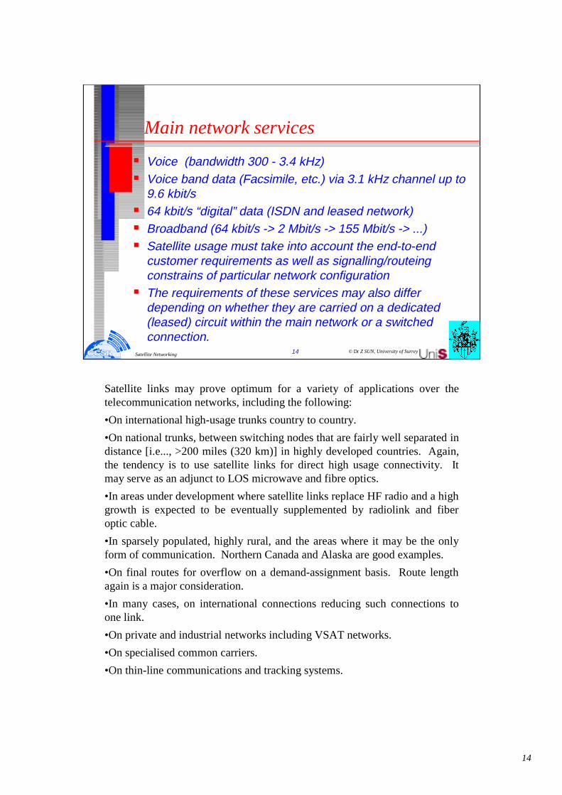
Main network services
� Voice (bandwidth 300 - 3.4 kHz)� Voice band data (Facsimile, etc.) via 3.1 kHz channel up to
9.6 kbit/s� 64 kbit/s “digital” data (ISDN and leased network)� Broadband (64 kbit/s -> 2 Mbit/s -> 155 Mbit/s -> ...)� Satellite usage must take into account the end-to-end
customer requirements as well as signalling/routeing constrains of particular network configuration
� The requirements of these services may also differ depending on whether they are carried on a dedicated (leased) circuit within the main network or a switched connection.
Satellite links may prove optimum for a variety of applications over the telecommunication networks, including the following:
•On international high-usage trunks country to country.
•On national trunks, between switching nodes that are fairly well separated in distance [i.e..., >200 miles (320 km)] in highly developed countries. Again, the tendency is to use satellite links for direct high usage connectivity. It may serve as an adjunct to LOS microwave and fibre optics.
•In areas under development where satellite links replace HF radio and a high growth is expected to be eventually supplemented by radiolink and fiberoptic cable.
•In sparsely populated, highly rural, and the areas where it may be the only form of communication. Northern Canada and Alaska are good examples.
•On final routes for overflow on a demand-assignment basis. Route length again is a major consideration.
•In many cases, on international connections reducing such connections to one link.
•On private and industrial networks including VSAT networks.
•On specialised common carriers.
•On thin-line communications and tracking systems.

15
© Dr Z SUN, University of Surrey15Satellite Networking
Network architecture
International Node
Main Network
Node
Local Network
Node
Customer’s terminal
International Node
Main Network
Node
Local Network
Node
Customer’s terminal
Switching function
Switching function
Main Network
Node
Local Network
Node
Main Network
Node
Local Network
Node
INTERNATIONAL NETWORK
Before 1980 the ITU-T routing plan was based on a network with a hierarchical structure with descending levels called CT1, CT2, CT3, and CTX (central transits), Since 1980 ITU-T has made a radical change in its international routing plan. The new plan might be called a "free routing structure." It assumes that national administrations (telephone companies) will maintain national hierarchical networks. Obviously the change was brought about by the long reach of satellite communications with which international high-usage (HU) trunks can terminate practically anywhere in the territory of a national administration.
The CCITT International Telephone Routing Plan is contained in CCITT Rec. E.171 and is reviewed below.
In practice, the large majority of international telephone traffic is routed on direct circuits (i.e.., no intermediate switching point) between international switching centres (ISCs). It should be noted that it is the rules governing routing of connections consisting of a number of circuits in tandem that this recommendation primarily addresses. These connections have an importance in the network because:
•they are used as alternate routes to carry overflow traffic in busy periods to increase network efficiency
•they can provide a degree of service protection in the event of failure of other routes
•they can facilitate network management when associated with ISCs having temporary alternative routing capabilities.
16
© Dr Z SUN, University of Surrey16Satellite Networking
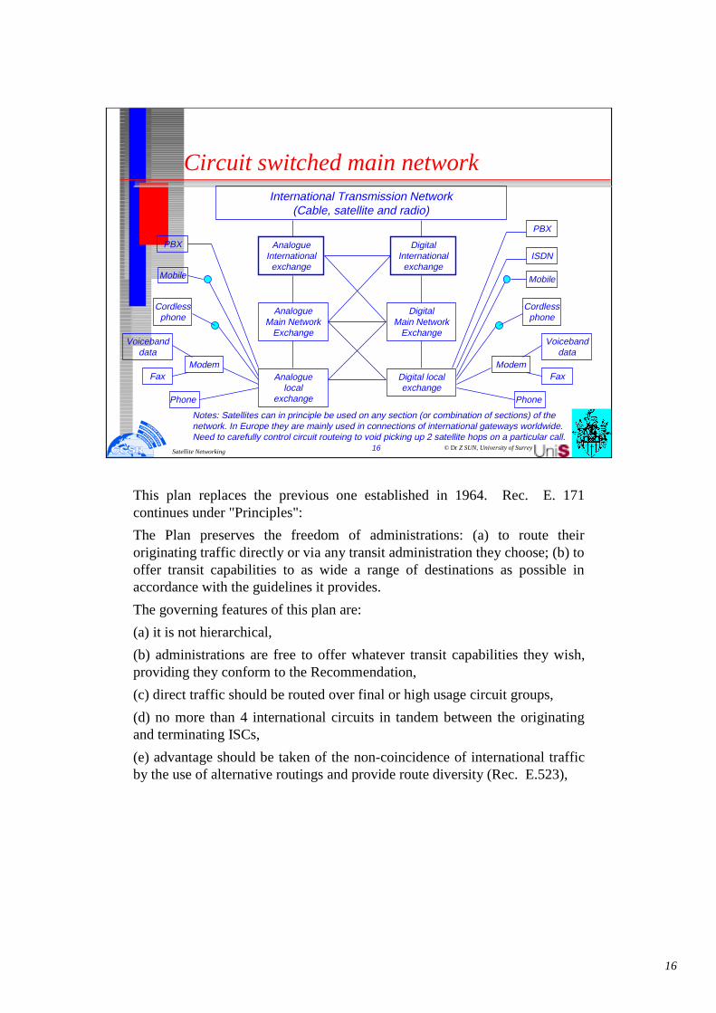
Circuit switched main networkInternational Transmission Network
(Cable, satellite and radio)
Analogue International
exchange
Analogue Main Network
Exchange
Analogue local
exchangePhone
Fax
Voicebanddata
Cordless phone
Mobile
PBX
Modem
Digital International
exchange
Digital Main Network
Exchange
Digital local exchange
Phone
Fax
Voicebanddata
Cordless phone
Mobile
ISDN
Modem
PBX
Notes: Satellites can in principle be used on any section (or combination of sections) of the network. In Europe they are mainly used in connections of international gateways worldwide. Need to carefully control circuit routeing to void picking up 2 satellite hops on a particular call.
This plan replaces the previous one established in 1964. Rec. E. 171 continues under "Principles":
The Plan preserves the freedom of administrations: (a) to route their originating traffic directly or via any transit administration they choose; (b) to offer transit capabilities to as wide a range of destinations as possible in accordance with the guidelines it provides.
The governing features of this plan are:
(a) it is not hierarchical,
(b) administrations are free to offer whatever transit capabilities they wish, providing they conform to the Recommendation,
(c) direct traffic should be routed over final or high usage circuit groups,
(d) no more than 4 international circuits in tandem between the originating and terminating ISCs,
(e) advantage should be taken of the non-coincidence of international traffic by the use of alternative routings and provide route diversity (Rec. E.523),

17
© Dr Z SUN, University of Surrey17Satellite Networking
Main network transmission � Local Access
• Analogue: standard 2-wire, 3.1 kHz local line• 64 kbit/s: leased line for access using ITU-T X-series
interfaces• 144 kbit/s: ISDN two 64 kbit/s information channels
plus a 16 kbit/s signalling link to control these channels • 2 Mbit/s: used for wideband leased circuit access or to
connect a PBX with 30x64 kbit/s information channels plus a 64 kbit/s signalling channel.
� Main Network• Analogue transmission (this is being replaced by digital
transmission• Digital transmission (120 Mbit/s TDMA, IDR 2 Mbit/s)
(f) the routing of transit switched traffic should be planned to avoid possibility of circular routings,
(g) when a circuit group has both terrestrial and satellite circuits, the choice of routing should be governed by:
•the guidance given in (CCITT) Rec. G. 114 (e.g., no more than 400 ms one-way propagation time),
•the number of satellite circuits likely to be utilised in the overall connection,
•the circuit which provides the better transmission quality and overall service quality,
(h) the inclusion of two or more satellite circuits in the same connection should be avoided in all but exceptional cases. Regarding (h), reference should be made to Annex A of Recs. E. 171 and Q. 14.

18
© Dr Z SUN, University of Surrey18Satellite Networking
Analogue transmission hierarchy
Single Channel (3100 Hz)
Group (12 or 16 channels)
Super-Group (60 channels)
Master-Group (300 Channels)
12 MHz (2700 Channels)
16 Super-Group (960 channels)
60 MHz (10800 Channels)
12 MHz (2700 Channels)
Super-Master-Group (900 Channel)
Hyper-Group (900 Channels)
nLower order systems from a single channel up to 60 channels.nHigher order systems from 300 up to 10800 channels
Notes: Analogue satellite channels using a variety of access/modulation techniques are still used internationally to support this hierarchy. This is rapidly being replaced in the network by the digital hierarchies.
This uses mainly FDMA.
19
© Dr Z SUN, University of Surrey19Satellite Networking
PDH and SDH transmissions technology

20
© Dr Z SUN, University of Surrey20Satellite Networking
History of Digital Transmission Systems
� Until 1970 achievement in long-haul routes: • Frequency Division Multiplexing (FDM)
� Early 1970s begin to appear:• Digital Transmission Systems
� Pulse Code Modulation (PCM) technique• Represent standard 4 kHz analogue telephone signal as a 64
Kbit/s digital bit stream
A Brief History of Transmission Systems
In the early 1970s, digital transmission systems began to appear, utilizing a method known as Pulse Code Modulation (PCM), first proposed in 1937. PCM allowed analogue waveforms, such as the human voice, to be represented in binary form, and using this method it was possible to represent a standard 4 kHz analogue telephone signal as a 64 kbit/s digital bit stream. Engineers saw the potential to produce more cost effective transmission systems by combining several PCM channels and transmitting them down the same copper twisted pair as had previously been occupied by a single analogue signal.
In Europe, and subsequently in many other parts of the world, a standard TDM scheme was adopted whereby thirty 64 kbit/s channels were combined, together with two additional channels carrying control information, to produce a channel with a bit rate of 2.048 Mbit/s.
As demand for voice telephony increased, and levels of traffic in the network grew ever higher, it became clear that the standard 2 Mbit/s signal was not sufficient to cope with the traffic loads occurring in the trunk network. In order to avoid having to use excessively large numbers of 2 Mbit/s links, it was decided to create a further level of multiplexing. The standard adopted in Europe involved the combination of four 2 Mbit/s channels to produce a single 8 Mbit/s channel. This level of multiplexing differed slightly from the previous in that the incoming signals were combined one bit at a time instead of one byte at a time i.e.. bit interleaving was used as opposed to byte interleaving. As the need arose, further levels of multiplexing were added to the standard at 34 Mbit/s, 140 Mbit/s, and 565 Mbit/s to produce a full hierarchy of bit rates.

21
© Dr Z SUN, University of Surrey21Satellite Networking
Transmission Hierarchies
64 Kbit/s64 Kbit/s
15441544
20482048
North American
Europe
X24
63126312 4473644736X4 X7 X6
X4 X4 X4 X4X30
274176274176
84488448 3436834368 139264139264 564992564992
X3X3
Deployment of synchronous transmission systems will be straightforward due to their ability to interwork with existing plesiochronous systems. The SDH defines a structure which enables plesiochronous signals to be combined together and encapsulated within a standard SDH signal. This protects network operators’ investment in plesiochronous equipment, and enables them to deploy synchronous equipment in a manner suited to the particular needs of their network.
As synchronous equipment becomes established within the network, the full benefits it brings will become apparent. The network operator will experience significant cost savings associated with the reduced amount of hardware in the network, and the increased efficiency and reliability of the network will lead to savings resulting from a reduction in maintenance and operations. Another result of increased reliability will be a reduction in the need to hold spare equipment.
The sophisticated network management capabilities of a synchronous network will give a vast improvement in the control of transmission networks. Improved network restoration and reconfiguration capabilities will result in better availability, and faster provisioning of services.
SDH has been designed to support future services such as Metropolitan Area Networks (MANs), Broadband ISDN, and personal Communications networks.

22
© Dr Z SUN, University of Surrey22Satellite Networking
Principles of Plesiochronous Operation
" Greek meaning of plesiochronous: almost synchronous"
1234
123
"fast" incoming bitsat 2 Mbit/s channel
"slow" incoming bitsat 2 Mbit/s channel
Bit rate adaptor
1234JJ
Bit rate adaptor
123JJJ
Masteroscillator
Less justification bit added
More justification bit added
Principles of Plesiochronous Operation
The multiplexing hierarchy described above appears simple enough in principle but there are complications. When multiplexing a number of 2Mbit/s channels they are likely to have been created by different pieces of equipment, each generating a slightly different bit rate. Thus, before these 2Mbit/s channels can be bit interleaved they must all be brought up to the same bit rate adding ’dummy’ information bits, or ’justification bits’. The justification bits are recognize as demultiplexing occurs, and discarded, leaving the original signal. This process is know as plesiochronous operation, from Greek, meaning “almost synchronous”.
The same problems with synchronization, as described above, occur at every level of the multiplexing hierarchy, so justification bits are added at each stage. The use of plesiochronous operation throughout the hierarchy has led to adoption of the term “plesiochronous digital hierarchy”, or PDH.
23
© Dr Z SUN, University of Surrey23Satellite Networking
The Synchronous Digital Hierarchy (SDH)
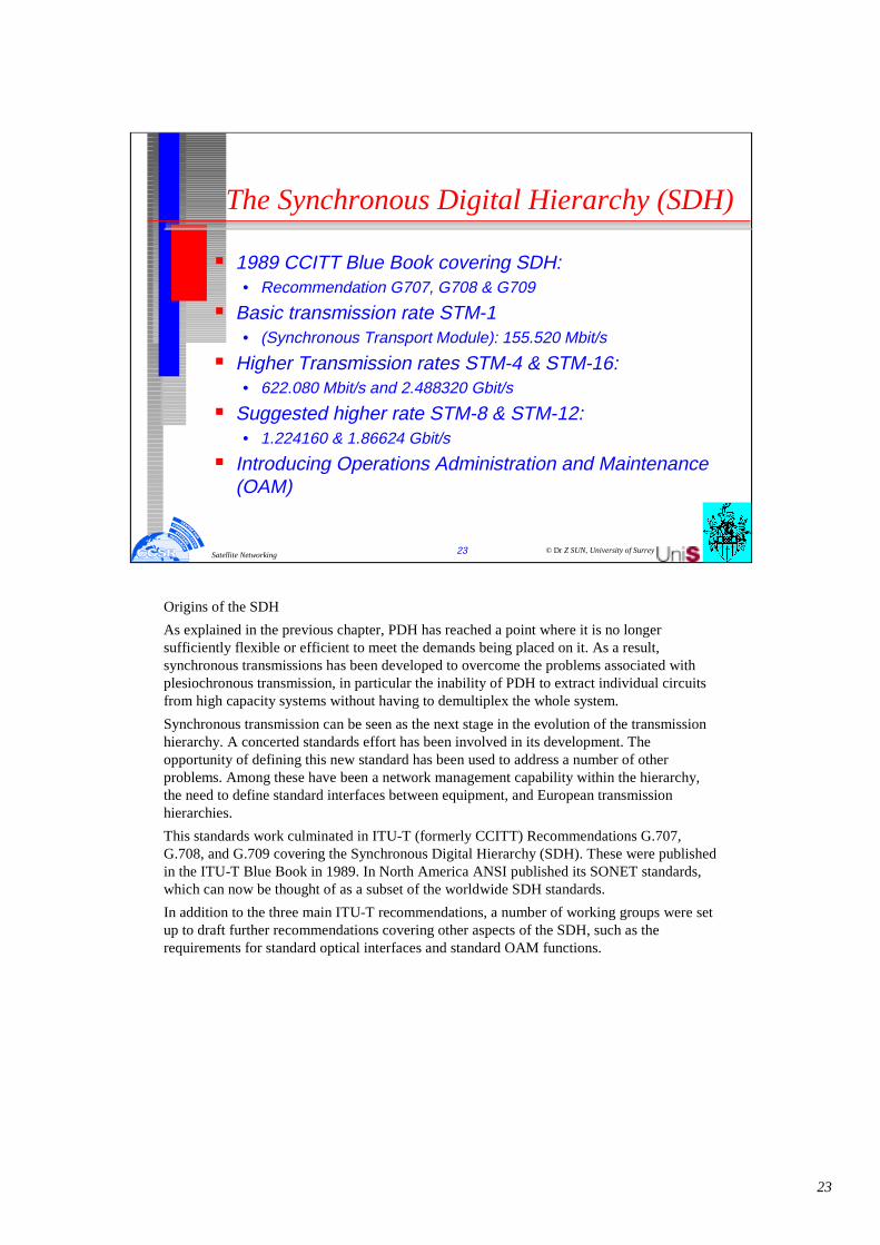
� 1989 CCITT Blue Book covering SDH: • Recommendation G707, G708 & G709
� Basic transmission rate STM-1• (Synchronous Transport Module): 155.520 Mbit/s
� Higher Transmission rates STM-4 & STM-16:• 622.080 Mbit/s and 2.488320 Gbit/s
� Suggested higher rate STM-8 & STM-12:• 1.224160 & 1.86624 Gbit/s
� Introducing Operations Administration and Maintenance (OAM)
Origins of the SDH
As explained in the previous chapter, PDH has reached a point where it is no longer sufficiently flexible or efficient to meet the demands being placed on it. As a result, synchronous transmissions has been developed to overcome the problems associated withplesiochronous transmission, in particular the inability of PDH to extract individual circuits from high capacity systems without having to demultiplex the whole system.
Synchronous transmission can be seen as the next stage in the evolution of the transmission hierarchy. A concerted standards effort has been involved in its development. The opportunity of defining this new standard has been used to address a number of other problems. Among these have been a network management capability within the hierarchy, the need to define standard interfaces between equipment, and European transmission hierarchies.
This standards work culminated in ITU-T (formerly CCITT) Recommendations G.707, G.708, and G.709 covering the Synchronous Digital Hierarchy (SDH). These were published in the ITU-T Blue Book in 1989. In North America ANSI published its SONET standards, which can now be thought of as a subset of the worldwide SDH standards.
In addition to the three main ITU-T recommendations, a number of working groups were set up to draft further recommendations covering other aspects of the SDH, such as the requirements for standard optical interfaces and standard OAM functions.

24
© Dr Z SUN, University of Surrey24Satellite Networking
Digital transmission hierarchy (SDH)
� The “primary rate” STM-1 (synchronous transport module - 1) has a bit rate of 155.520 Mbit/s
� Each frame consists of “payload” space of carrying a PDH 140 Mbit/s signal completely, with extra capacity for error-checking and management channels.
� The current defined higher SDH levels are STM-4 (4 STM-1s) and STM-16 (16 STM-1s).
� The proposed STM-R, the reduced bitrate STM-1 is an attempt to design STM with a bit rate of 51.84 Mbit/s.
� The satellite community should note that all levels of the SDH contain a considerable percentage of overhead (3.33%) much of which is at present undefinded.
The ITU-T recommendations define a number of basic transmission rates within the SDH. The first of these is 155 Mbit/s, normally referred to as STM - 1 (where STM stands for ’synchronous Transport Module’). Highertransmission rates of STM - 4 and STM - 16 (622 Mbit/s and 2.4 Gbit/s respectively) are also defined, with further levels proposed for study.
The recommendations also define a multiplexing structure whereby an STM -1 signal can carry a number of lower rate signals as payload, thus allowing existing PDH signals to be carried over a synchronous network. This process will be explained in more detail below.

25
© Dr Z SUN, University of Surrey25Satellite Networking
Mapping PDH to SDH
STM-NXN
AUGX1
AU-4
AU-3
VC-4
VC-3
TUG-3
TUG-2 TU-2X1
VC-2
C-4
TU-12
X3
VC-12 C-12
TU-11
X4
VC-11 C-11
C-2
C-3
140 Mb/s
45/34 Mb/s
TU-3 VC-3X3
X3
6 Mb/s
2 Mb/s
1.5 Mb/s
X7
X7
s
s
s
s
e
e
e
X1 e
s: ANSI SONET specific optione: Europe ETSI specific option
AUG: Administrative Unit GroupTUG: Tributary Unit GroupVC: Virtual Container
multiplexingmappingaligning
Principles of the Synchronous Digital Hierarchy (SDH)
Despite its obvious advantages over PDH, SDH would have been unlikely to have gained acceptance if its adoption had immediately made all existing PDH equipment obsolete. This is why the ITU-T Recommendations made provisions from the outset for any currently used transmission rate to be packaged into an STM-1 frame. All plesiochronous signals between 1.5 Mbit/s and 140Mbit/s can be accommodated, with the ways in which they can be combined to form an STM-1 signal defined in Recommendation G.709. The SDH multiplexing hierarchy is shown in the slide. A brief explanation of how the hierarchy works follows.
Mapping PDH to SDH
SDH defines a number of “Containers”, each corresponding to an existing plesiochronousrate. Information from a plesiochronous signal is mapped into the relevant container. The way in which this is done is similar to the bit stuffing procedure carried out in a conventional PDH multiplexer. Each container then has some control information known as the “path overhead” added to it . The path overhead bytes allow the network operator to achieve end-path monitoring of things such as error rates. Together the container and the path overhead form a “Virtual Container”.

26
© Dr Z SUN, University of Surrey26Satellite Networking
Simplification of PDH Add-Drop principle
140 Mbit/s line terminator
140
34
140
34
140
34
140 Mbit/s line terminator
140
34
140
34
140
34
Customer site
PDH
Customer site
SDH
SDH
Multipleter
SDH
Multipleter
SDH
Multipleter
In a synchronous network, all equipment is synchronised to an overall network clock. It is important to note, however, that the delay associated with a transmission link may vary slightly with time. As a result, the location of virtual containers within an STM-1 frame may not be fixed. These variations are accommodated by associating a pointer with each VC. The pointer indicates the position of the beginning of the VC in relation to the STM-1 frame. It can be increased or decreased as necessary to accommodate of the position of the VC.
G.709 defines different combinations of virtual containers which can be used to fill up the payload area of an STM - 1 frame. The process of loading containers, and attaching overhead is repeated at several levels in the SDH, resulting in the “nesting” of smaller VCs within larger ones. This process is repeated until the largest size of VC (a VC - 4 in Europe) is filled, and this is then loaded into the payload of the STM - 1 frame. (This subject will be discussed in more detail in Chapter 4). When the payload area of the STM - 1 frame is full, some more control information bytes are added to the frame to form the “Section Overhead”. The section overhead bytes are so-called because they remain with the payload for the fibersection between two synchronous multiplexers. Their purpose is to provide communication channels for functions such as OAM; facilities, alignment and a number of other functions.
When a higher transmission rate than 155 Mbit/s of STM-1 is required in synchronous network, it is achieved by using a relatively straightforward byte - interleaved multiplexing scheme. In this way, rates of 622 Mbit/s (STM - 4) and 2.4 Gbit/s (STM - 16) can be achieved.

27
© Dr Z SUN, University of Surrey27Satellite Networking
Synchronous Operation
Example: European mapping route for primary rate service
STM-1X1
AU-4 VC-4 TUG-3 TUG-2
TU-12
X3
VC-12 C-12
VC-11 C-11
2 Mb/s
1.5 Mb/s
s: ANSI SONET specific optione: Europe ETSI specific option
AUG: Administrative Unit GroupTUG: Tributary Unit GroupVC: Virtual Container
multiplexingmappingaligning
AUGX1 X3 X7
s
Synchronous Operation
The basic element of the STM signal consisting of a group of bytes allocated to carry the transmission rates defined in G.702 (i.e.. 1.5Mbit\s and 2Mbit\s transmission hierarchies).
VIRTUAL CONTAINER VC-n : (n = 1-4)
Built up from the container plus additional capacity to carry the path overhead (POH). The path overhead provides end-to-end path control and monitoring information.
For a VC-3 or VC-4 the payload may be a number of TUs or TUGs as opposed to a simple basic vc-n, where n=1,2.
TRIBUTARY UNIT TU-n: (n= 1-3)
The tributary unit consists of a Virtual Container plus a Tributary Unit Pointer. The position of the VC within the TU is not fixed, however the position of the TU pointer is fixed with relation to the next step of the multiplex structure, and indicates the start of the VC.
TRIBUTARY UNIT GROUP TUG:
This is formed by a group of identical TUs.
ADMINISTRATION UNIT AU-n: (n=3,4)
This consists of a VC plus an AU pointer. The phase alignment of the AU pointers are fixed with relation to the STM-1 frame as a whole and indicate the positions of the VC.

28
© Dr Z SUN, University of Surrey28Satellite Networking
Transmission rates
Levels Referring to SDH:
STM-1: 155.520 Mbit/s
STM-4: 622.080 Mbit/s
STM-8: 1224.160 Mbit/s
Sugested high rates:
STM-12: 1866.240 Mbit/s
STM-16: 2488.320 Mbit/s
Levels Referring to PDH:
11 1.544 Mbit/s
12 2.048 Mbit/s
21 6.312 Mbit/s
22 8.488 Mbit/s
31 34.368 Mbit/s
32 44.736 Mbit/s
4 139.264 Mbit/s
SYNCHRONOUS TRANSPORT MODULE: LEVEL 1 (STM-1)
This is the basic element of the SDH. It is formed from a payload (made up of the AU) and additional bytes to form a section overhead (SOH). The section overhead allows control information to be passed between adjacent synchronous network elements.
SYNCHRONOUS TRANSPORT MODULE: LEVEL N (STM-N)
Formed by combining lower level STM signals using byte interleaving. The basic transmission rate defined in the SDH standards is 155.520 Mbit/s (STM-1). Given that an STM-1 frame consists of 2430 8-bit bytes, this corresponds to a frame duration of 125 microseconds. Two higher bit rates are also defined: 622.080 Mbit/s (STM-4) and 2,488.320Mbit/s (STM-16).
Within an STM-1 frame, information type repeats every 270 bytes. Thus, the STM-1 frame is often considered as a 270 byte x 9 line structure, as shown in the figure bellow. The first 9 columns of this structure constitutes the “Section Overhead” area, while the remaining 261 columns are the “Payload” area.
The synchronous digital hierarchy does away with a number of the lower multiplexing levels defined in PDH. 2 Mbit/s tributaries are multiplexed to the STM-1 level in a single step. However, in order to achieve compatibility with non-synchronous equipment, the SDH recommendations define methods of subdividing the payload area of an STM-1 frame in various ways so that it can carry different combinations of tributaries, both synchronous and asynchronous. Using this method, synchronous transmission systems can accommodate signals generated by equipment from various levels of the plesiochronous digital hierarchy.

29
© Dr Z SUN, University of Surrey29Satellite Networking
The STM-1 Frame270 bytes
11
2
3
4
5
6
7
8
9
Section overhead
AU ptr
Section overhead
9 10 270
9 bytes
125 microseconds
STM-1 Payload
J1
B3
C2
G1
F2
H4
Z3
Z4
Z5
VC-4
POH
The STM-1 Frame
As was explained in the last section an STM-1 frame consists of 2430 bytes which can be considered as a structure of 270 columns x 9 lines. The frame is divided into three main sections:
•Payload Area
•AU Pointer Area
•Section Overhead Area
PAYLOAD
We have seen previously that signals from all levels of the PDH can be accommodated in a synchronous network by packaging them together in the payload area of an STM-1 frame.
The plesiochronous tributaries are mapped into the appropriate synchronous container, and a single column of nine bytes, known as the Path Overhead (POH), is added to form the relevant Virtual Container (VC). The path overhead provides information for use in end-to-end management of a synchronous path.
The slide describes VC-4 packaging with VC-4 Path Overhead
B3 BIP-8 (Bit Interleaved Parity): This byte provides bit error monitoring over the path using an even bit parity code, BIP-8.
C2 Signal Label: This byte indicates the composition of the VC-n payload.
F2 Path User Channel: This byte provides a user communication channel.
G1 Path Status: This byte allows the status of the received signal to be returned to the transmitting end of the path from the receiving end.
H4 Multiframe indicator: Single byte for multiframe indication.
J1 Path Trace: This byte verifies the VC-n path connection.
Z3-Z5: Three bytes for National use.
After the path overhead is added, a pointer indicates the start of the VC relative to the STM-1 frame. This unit is then known as a Tributary Unit (TU) if it carries lower order tributaries, or an Administrative Unit (AU) for higher order.

30
© Dr Z SUN, University of Surrey30Satellite Networking
STM-1 Section Overhead
Bytes reserved for future use. For example, these are proposed by whin ITU-T to be used for media specific applications, e.g. Forward error correction in radio systems.
A1 A1 A1 A2 A2
B1
D1
AU pointers
A2 C1
B2 B2 B2 K1 K2
D4
E1
D5 D6
D7 D8 D9
D10
Z1 Z1 Z1 Z2 Z2 Z2 E2
D11 D12
D2 D3
F1
Regenerator section overhead
Multiplex section overhead
STM-1 Payload
TUs can be bundled together into Tributary Unit Groups (TUGs), which are then mapped into a higher order VC.Once the STM-1 payload area is filled by the largest unit available, a pointer is generated which indicates the position of the unit in relation to the STM-1 frame. This is known as the AU pointer. It forms part of the section overhead area of the frame.The use of pointers in the STM-1 frame structure means that plesiochronous signals can be accommodated within the synchronous network without the use of buffers. This is because the signal can be packaged into a VC and inserted into the frame at any point at time. The pointer then indicates its position. Use of the pointer method was made possible by defining synchronous virtual containers as slightly larger than the payload they carry. This allows the payload to slip in time relative to the STM-1 frame in which it is contained.Adjustment of the pointers is also possible where slight changes of frequency and phase occur as a result of variations in propagation delay and the like.The result of this is that in any data stream, it is possible to identify individual tributary channels, and drop or insert information, thus overcoming one of the main drawbacks of PDH.Section OverheadThe Section Overhead (SOH) bytes are used for communication between adjacent pieces of synchronous equipment. As well as being used for frame synchronization, they perform a variety of management and administration facilities. The purpose of individual bytes is detailed below:A1, A2: FramingB1, B2: These bytes are simple parity checks for error detection.C1: Identifies an STM-1 in an STM-N frame.D1-D12: Data communication channel. Used for network management.E1, E2: Orderwire channels.F1: User channel.K1, K2: Automatic Protection Switching (APS) channelZ1, Z2: Reserved bytes for National use.

31
© Dr Z SUN, University of Surrey31Satellite Networking
SDH over satellite - Intelsat Scenarios (1/2)
� Full STM-1 transmission (point to point) through a standard 70 MHz transponder.
� STM-R uplink with STM-1 downlink (point to multipoint)
Intelsat, in conjunction with its signatories and ITU-T & ITU-R standards bodies has developed a series of SDH compatible network configurations with satellite forming part of the transmission link. A full description of these network configurations, refer to by Intelsat as “scenarios”, is out side the scope of this lecture. Recent chairman’s report of the ITU-R SG4 contain fuller descriptions of these scenarios. In summary, the options are as follows:
(a) Full STM-1 transmission (point to point) through a standard 70 MHz transponder. -This requires the development of an STM-1 modem capable of converting the STM-1 digital signal to an analogue format which can be transmitted through a standard 70 MHz transponder. While this development work is generally supported by the Intelsat signatories, there is limited confidence that this approach will yield reliable long term results. It has been suggested in the Technical Advisory committee of the Intelsat Board of Governors that the carriage of an STM-1 will very closely approach the theoretical limits of a 70 MHz transponder.
In addition there is (as yet) no recognised need for this amount of capacity via an SDH satellite links. Current high bit rate PDH IDR links are generally used for submarine cable restoration (although there are some exceptions), but for SDH cables, the capacity of submarine cables is such that a complete current generation Intelsat satellite would have to be held in reserve for SDH restoration. This is clearly not a cost-effected use for telecommunication satellites.
(b) STM-R uplink with STM-1 downlink (point to multipoint) - This scenario suggests a multi-destinational system, and requires considerable on-board processing of SDH signals, however, the advantage is flexible transponder usage for the network operator(s) using the system. This approach is not generally favoured by most network operators for reliability and future proofing reasons. This approach may prevent alternative usage of the satellite transponders in the future, and additional complexity is likely to reduce the reliability/lifetime of the satellite, and increase its initial expense.

32
© Dr Z SUN, University of Surrey32Satellite Networking
SDH over satellite - Intelsat Scenarios (2/2)
� Intermediate data rate (IDR) of 2 Mbit/s � PDH IDR link with SDH to PDH conversion at the earth
station
(c) Extended TU-12 Intermediate data rate (IDR) of 2 Mbit/s - This approach is favoured by a large number of signatories, since it retains the inherent flexibility of the satellite (regarded as a major advantage over cable systems), and would require the minimum of alterations to satellite and earth station design. Additionally, some of the management advantages of SHD are retained, including end-to-end path performance monitoring, signal labelling and other part of the “Overhead”. Current development work is centred around determining what aspects of the Data Communication Channels could also be carried with the TU-12.
Since the bit rate of the TU-12 is not much greater than an existing 2 Mbit/s PDH signal, it is likely that minimal rearrangement of the transponder band-plans would be required, with the possibility of mixing PDH and SDH compatible IDR carriers. Additionally, development work is currently taking place to modify existing IDR modems to carry the TU-12 signal, rather than more expensive options of develop new modems (for example, for the STM-1 and STM-R options.
(d) PDH IDR link with SDH to PDH conversion at the earth station - This is the simplest option of all, but provide the operator with any SDH compatibility. All the advantages of SHD are lost, with additional costs incurred in the SDH to PDH conversion equipment. In the early days of SDH implementation, it mat be the only available method, however.

33
© Dr Z SUN, University of Surrey33Satellite Networking
Satellite system performance related to service requirement
� Echo: some form of echo control is always advisable on satellitebased networks carrying voice traffic, irrespective of the associated delay.
� Delay: the one way propagation delay between satellite earth station via a geostationary satellite is approximately 260 ms - see ITU-T G.114
� Digital transmission error performance objective:• G.821 based on 64 Kbit/s circuit switched connection:
– Bit Error Ratio (BER): is the ratio of the number of bits in error to the total number of bits transmitted during a measurement period. Objective is to get BER < 10 E-6.
– Errored second (ES) - BER > 10E-6– Severely errored second (SES) - BER > 10E-3
• G.826: define ES and SES differently at high bit rates
Echo: some form of echo control is always advisable on satellite based networks carrying voice traffic, irrespective of the associated delay. The ITU-T recommends if the mean round-trip propagation time exceed 50 ms for a particular circuit, an echo suppresser or echocancellor should be used.
Delay: the one way propagation delay between satellite earth station via a geostationarysatellite is approximately 260 ms - see ITU-T G.114).
Errors: The principle measure of quality of service (QoS) of a data circuit is its error performance. The parameters are defined In G821: “the percentage of averaging periods each of time interval T(0) during which the error bit rate (BER) exceeds a threshold value. The percentage is assessed over a much longer time interval T(L)”. A suggested T(L) is 1 month.
ITU-T G.821 based on 64 Kbit/s circuit switched connections:
•BER: is the ratio of the number of bits in error to the total number of bits transmitted during a measurement period. Objective is to get BER < 10 E-6.
•Errored second (ES): is any 1-s interval containing at least 1 error.Objective is to get fewer than 8% of 1-second intervals to have any errors worse (equivalent to 92% error free seconds).
•Severely errored second (SES): is any 1-s interval with BER > 10E-3.Objective is to get Fewer than 0.2% of 1-second intervals to have a bit errors worse that 1x10E-3.
ITU-T G.826 makes use of block-based error measurement so that in-service (error) measurements (ISM) are easier to carry out.
•Error block (EB): a block one or more bits are in error
•Error Second (ES): A 1-second period with one or more errored blocks.
•Severely Error Second (SES): A 1-second period that contain more than 30% Ebs.
•Background block error (BBE): An EB not occurring as part of an SES.

34
© Dr Z SUN, University of Surrey34Satellite Networking
Error Performance Objectives for G.826
� Hypothetical reference path (HRP)
Path end point (PEP)
Path end point (PEP)
Intermediate countries (4 assumed)
IG IG IG IG IG IG
Intercountrypath (e.g. cable, sat.)
International portion
Hypothetical reference path: 27,500 km
Terminating country
Terminating country
IG: International Gateway
2% 2% 2% 2%
17%
17%
1% 1%
1% per 500 km
•ES ratio (ESR): The ratio of ESs to total seconds available time during a fixed measurement interval.
•SES ratio (SESR): The ratio of SESs to total seconds in available time during a fixed measurement interval.
•BBE ratio: The ratio of Ebs to total blocks during a fixed measurement interval, excluding SESs and unavailable time.
Error performance objectives (EPOs) are measured over available time in a fixed measurement interval. All three objectives (i.e.., ESR, SESR and BBER) must hold concurrently to satisfy G.826, they apply end-to-end for a 27,500 km hypothetical reference path (HRP), which is shown in the slide. The following table show the objectives for G826:
Under the assumption of 4 intermediate countries and no satellite hop, the following breakdown for the apportionment can be obtained. Terminating Countries: 2 x 17.5% + 2 x1% = 37%Intermediate Countries: 4 x 2% = 8%Distance allowance: (27500/500) x 1% = 55%Total: 100%
If satellites are used, each receive 35% of the apportionment which corresponding to a nominal hop distance of 17,500 km. But the distance of the hop is removed from the distance allowance.
Rate (Mbit/s) Bits/block ESR SESR BBER1.5 - 5 2000 - 8000 0.04 0.002 3 x 10 e-45 - 15 2000 - 8000 0.05 0.002 2 x 10 e-415 - 55 4000 - 20000 0.075 0.002 2 x 10 e-455 - 160 6000 - 20000 0.16 0.002 2 x 10 e-4
35
© Dr Z SUN, University of Surrey35Satellite Networking
ISDN over Satellite

36
© Dr Z SUN, University of Surrey36Satellite Networking
Issues on ISDN?
� The ITU definition of an Integrated Services Digital Network (ISDN) is:
A network evolved from the telephony IDN that provides end-to-end digital connectivity to support a wide range of services, including voice and non-voice services, to which users have access by a limited set of standard multipurpose customer interfaces.
ISDN is an effort to standardize subscriber services, user/network services and inter-network capabilities. It is supposed to ensure a level of international compatibility.
Standardizing the User and Network Interfaces (UNI) stimulates development
and marketing not only by large manufacturers of central office equipment
but also by third party manufacturers. It achieved the goal of Worldwide
Connectivity because ISDN easily provides intercommunication
between them.
The ISDN UNI includes beyond the physical network a wide range of protocols. The ISDN Standards with the advantages provide the
telecommunication world with new capabilities for users and standardizes
connection to most equipment/networks. It also gives a good start for new
standards like Broadband-ISDN and ATM.

37
© Dr Z SUN, University of Surrey37Satellite Networking
ISDN Access
� Two customer access schemes - the basic rate access and the primary rate access.
� Large business customers will access an ISDN network via a digital PABX at the primary (or possibly higher) PCM multiplex rates of 1.544 (US) or 2.048 Mbits/s (European)
� This corresponds to a TDM group of 30 B-channels in Europe (or 23 in US) plus 1 D-channel operating at 64 kbits.
� The signalling over this D-channel will be handled using an extension to the No 7 signalling scheme.
� The small business or domestic customer will access at 2 B-channels of b4 Kbit/s plus a D-channel of 16 Kbit/s
BASIC RATE INTERFACE (BRI)
The basic rate interface is specified in ITU-T recommendation I.430.
The recommendation defines ISDN communication between terminal equipment. The BASIC RATE INTERFACE (BRI) comprises two B-channels and one D-channel (2B+D).
Basic rate access may use a point-to-point or point-to-multipoint configuration. In a point-to-point configuration, the network terminals (NT1 or NT2) and terminals equipment (TE1 or TA) can be up to 1 km apart.
The physical connection between the TE and NT requires at least two wire pairs, one pair for each direction of transmission, these are the transmit and receive loops.
The ISDN TAs and TEs will have some internal memory identifying its address and bearer service attribute profile and supporting the ISDN protocols.
Primary rate interface (PRI)
The PRI is defined by physical layer protocol and also by higher protocols included LAPD. It has a full duplex point to point serial, synchronous configuration. The CCITT recommendation G703, G704 defines the electrical interfaces and the frame formats.
There are two different interfaces:
North America T1 (1.544Mbit/s): It multiplexes 24 of 64khz channels. One PRI frame contains 1 framing bit plus a single 8-bit sample from each of 24 channels-193 bits per frame.
Europe CEPT E1 (2.048Mbit/s): it multiplexes 32 channels.

38
© Dr Z SUN, University of Surrey38Satellite Networking
ISDN over satellite
Satellite links can easily support ISDN services with� Basic rate:
144 Kbit/s (2 x 64 Kbit/s B-channel + 16 Kbit/s D-channel)� Primary rate:
• 1.544 Mbit/s = 23B + D = 23x64 + 64 (for North America configuration)
• 2.048 Mbit/s = 30B + D = 30x64 + 2x64 (for Europe) -where one time slot is used for framing and one general network maintenance
� Routeing Plan - no hierarchical, no more than 2 hops

39
© Dr Z SUN, University of Surrey39Satellite Networking
ATM and B-ISDN over Satellite

40
© Dr Z SUN, University of Surrey40Satellite Networking
Broadband ?
� B-ISDN or Broadband ISDN: Broadband Integrated Services Digital Network
� ITU-T definition: • A service or system requiring transmission channels
capable of supporting rates greater than the primary rate.
ATM Fundamental Concept
From a technical point of view, the fundamental underpinning of ATM is:
•to support all existing services as well as emerging services in the future,
•fixed-size cells with VPI and VCI to minimises the switching complexity,
•statistical multiplexing to utilises network resources very efficiently,
•to minimise the processing time at the intermediate nodes and supports very high transmission speeds as well as very low speed by negotiate service contract for a connection with required quality of services,
•to minimise the number of buffers required at the intermediate nodes to bound the delay and the complexity of buffer management,
•guarantees performance requirements of existing and emerging applications,
•layered architecture, and
•Capable of handling bursty traffic.

41
© Dr Z SUN, University of Surrey41Satellite Networking
Relationship Between ATM and B-ISDN
� ATM evolved from the standardization efforts for B-ISDN. � ATM is the technology upon which B-ISDN is based.
ATM Principle
ATM is a fast packet oriented transfer mode based on asynchronous time division multiplexing and it uses fixed length (53 bytes) cells. Each ATM cell consists of a information field (48 bytes) and a header (5 bytes). The header is used to identify cells belonging to the same virtual channel and thus used in appropriate routing. Cell sequence integrity is preserved per virtual channel. ATM Adaptation layers (AAL) are used to support various services and provide service specific functions. This AAL specific information is contained in the information field of the ATM cell. Basic ATM cell structure is used for the following functions.
Routing
ATM is a connection oriented mode. The header values (i.e.. VCI and VPI etc.) are assigned during the connection set up phase and translated when switched from one section to other. Signalling information is carried on a separate virtual channel than the user information. In routing, there are two types of connections, i.e.., Virtual channel connection(VCC) and Virtual path connection(VPC). A VPC is an aggregate of VCCs. Switching on cells is first done on the VPC and then on the VCC.
ATM Resources Management
ATM is connection-oriented and the establishment of the connections includes the allocation of a virtual channel identifier (VCI) and/or virtual path identifier (VPI). It also includes the allocation of the required resources on the user access and inside the network. These resources, expressed in terms of throughput and quality of service, can be negotiated between user and network either before the call-set up or during the call.
ATM Cell Identifiers
ATM cell identifiers including VPI, VCI and Payload Type Identifier (PTI) are used to recognise an ATM cell on a physical transmission medium. VPI and VCI are same for cells belonging to the same virtual connection on a shared transmission medium.

42
© Dr Z SUN, University of Surrey42Satellite Networking
ATM Technology
� Cell Switching and fixed-length cells• 53 bytes cells• 48 payload and 5 byte header
� Negotiated Service Contract• Connection Oriented • end-to-end Quality of Services.
Head
5 Octets
Payload
48 Octets
Why 53 bytes?
Throughput
Peak Cell Rate (PCR) can be defined as a throughput parameter which in turn is defined as the inverse of the minimum interarrival time T between two consecutive basic events and T is the peak emission interval of the ATM connection. PCR applies to both constant bit rate (CBR) and variable bit rate (VBR) services for ATM connections. It is an upper bound of the cell rate of an ATM connection and there is another parameter sustainable cell rate (SCR) allows the ATM network to allocate resources more efficiently.
Quality Of Service
Quality of Service (QOS) parameters include cell loss, the delay and the delay variation incurred by the cells belonging to the connection in an ATM network. QOS parameters can be either specified explicitly by the user or implicitly associated with specific service requests. A limited number of specific QOS classes will be standardised in practice.
Usage Parameter Control
In ATM, excessive reservation of resources by one user affects traffic for other users. So the throughput must be policed at the user-network interface by a Usage Parameter Control (UPC) function in the network to ensure that the negotiated connection parameters per VCC or VPC between network and subscriber is maintained by each other user. Traffic parameters describe the desired throughput and QOS in the contract. The traffic parameters are to be monitored in real time at the arrival of each cell. ITU-T (formerly CCITT) recommends a check of the peak cell rate (PCR) of the high priority cell flow (CLP = 0) and a check of the aggregate cell flow (CLP = 0 and 1), per virtual connection.
Flow Control
In order to control the flow of traffic on ATM connections from a terminal to the network, a General Flow Control (GFC) mechanism is proposed by ITU-T at the User to Network Interface (UNI). This function is supported by GFC field in the ATM cell header. Two sets of procedures are associated with the GFC field, i.e.., Uncontrolled Transmission which is for use in point-to-point configurations and Controlled Transmission which can be used in both point-to-point and shared medium configurations.

43
© Dr Z SUN, University of Surrey43Satellite Networking
Mapping ATM into STM-1
270 bytes
11
2
3
4
5
6
7
8
9
Section overhead
AU ptr
Section overhead
9 10 270
9 bytes
125 microseconds
STM-1 Payload
J1
B3
C2
G1
F2
H4
Z3
Z4
Z5
VC-4
POH
...... ......
ATM Cells
155 Mbits/s, SONET STS-3c
Let’s start with SONET, which is probably the physical layer most often associated with ATM.
The essential feature of SONET is to keep track of boundaries of streams that don’t really depend on the particular medium. So, although we typically think about it as fibre, it will in fact operate over other media. Some of the work going on currently in The ATM Forum on a physical specification for using (copper) unshielded-twisted pair will be using the SONET type framing.
This is the SONET frame at 155 Mbits/s. To read this chart, start in the upper left-hand corner. The bytes are transmitted across the medium a row at a time, wrapping to the next row. By the time you go through all nine rows, the elapsed time is nominally 125 microseconds.
In the above figure, the first 9 bytes of each row have various overhead functions. For example, the first two bytes here are used to identify where the beginning of this frame is so the receiver can lock on to this frame.
In addition, although not shown here, there is another column of bytes which are included in the "Synchronous Payload Envelope" that are additional overhead, with the result that each row has 260 bytes of information. Consequently, 260 bytes per row times 9 rows times 8 bits divided by 125 microseconds, you get 149.76 Mbits/s of payload.
This is called the STS-3C. It is also known as the STM-1 because in the international carrier networks, this will be the smallest package that you’ll see available in terms of the Synchronous Digital Hierarchy (SDH), the international flavour of SONET. The bit rates for SDH STM-n are three times the bit rates for SONET STS-n for the same "n."
For Higher Bit Rate
SONET also has some nice features in that if you want to go to higher rates -- like 622Mbits/s -- it becomes basically a recipe of how you take four of these STM-1 structures and simply interleave the bytes to get to 622 Mbits/s (STM-4, or STS-12). There are additional steps up to 1.2 gigabits, 2.4 gigabits, etc. And -- at least in theory -- the recipe tells you how to get as high a speed interface as you would like.

44
© Dr Z SUN, University of Surrey44Satellite Networking
Mapping ATM into Cell Based Transmission
......1 2 26 27 28
......1 2 26 27 28
29
OMA Cell
ATM layer: 149.760 Mbit/s
Physical Layer: 155.520 Mbit/s
SONET Cell Delineation
The cells within the SONET payload are delineated by using the Header Error Check (HEC) in the ATM cell.
The receiver, when it’s trying to find the cell boundaries, takes five bytes and says, "I wonder if this five bytes is a header." It does the HEC calculation on the first four bytes and matches that calculation against the fifth byte. If it matches, the receiver then counts 48 bytes and tries the calculation again. And if it finds that calculation correct several times in a row, you can probably safely assume that in fact it’s found the cell boundaries. If it tries the calculation and it fails, you just slide the window and try the calculation again.
This kind of process must be used because, of course, we don’t really know what’s in the 48 bytes of payload, but the chances that the user data would contain these patterns separated by 48 bytes is essentially zero for any length of time.
Consider for a moment what happens if you come across a series of empty cells. Then how do you determine the cell boundaries? This is especially important since the a CRC for an all zero (empty cell) header would be all zeros. Consequently, the HEC must be based on something other than a simple CRC.
The answer is that the HEC is calculated by first calculating the CRC value, then performing an “exclusive or” operation of the CRC value with a bit pattern called the coset, resulting in a non-zero HEC. Thus, the HEC is unique from the zeros in the empty cells, and the HEC may still be used for cell delineation. At the receiving end, another "exclusive or" operation is performed, resulting in the original CRC for comparison.
If you calculate how much payload you get on a SONET STS-3C, it comes out to 135Mbits/s, assuming that the entire cell payload may carry user information. (The amount of the payload that actually carries information depends on the AAL in use.).

45
ATM layer
ATM layer is the layer above the physical layer. As shown in the , it does the 4 functions which can be explained as follows.
Cell header generation/extraction: This function adds the appropriate ATM cell header (except for the HEC value) to the received cell information field from the AAL in the transmit direction. VPI/VCI values are obtained by translation from the SAP identifier. It does opposite, i.e.. removes cell header in the receive direction. Only cell information field is passed to the AAL.
Cell multiplex and demultiplex: This function multiplexes cells from individual VPs and VCs into one resulting cell stream in the transmit direction. It divides the arriving cell stream into individual cell flows based on the cell header VCI or VPI in the receive direction.
VPI and VCI translation: This function is performed at the ATM switching and/or cross-connect nodes. At the VP switch, the value of the VPI field of each incoming cell is translated into a new VPI value of the outgoing cell. The values of VPI and VCI are translated into new values at a VC switch.
Generic Flow Control(GFC): This function supports control of the ATM traffic flow in a customer network. This is defined at the B-ISDN User-to-network interface (UNI).
The is a system whereby information is transferred asynchronously with its appearance at the input of the communications system. Information is buffered as it arrives and is inserted into an ATM cell when there is enough to fill the cell, the cell is then transported across the network. At a multiplexing stage a cell from a particular stream is transmitted as soon as there is an unused ATM cell available to carry it; if there is no information to be transmitted an idle cell is transmitted instead It is clear that the principle is very similar to that of a packet-switched network. However, ATM is different in several ways.
© Dr Z SUN, University of Surrey45Satellite Networking
ATM Layer - Head Structure
GFC
CLPPTVCI
VCI
VPI
VPI VCI
HEC
1 2 3 4 5 6 7 8
1
2
3
4
5
at the UNI
CLPPTVCI
VCI
VPI
VPI VCI
HEC
1 2 3 4 5 6 7 8
at the NNI

46
Virtual Connections
Once the cell size is fixed at 53 bytes, the next issue is how to get the cells from place to place.
The important fields for this in the header are the VPI/VCI fields, as shown in this example of a number of virtual connections through an ATM switch. Within the switch, there has to be a connection table (or routing table) and that connection table associates a VPI/VCI and port number with another port number and another VPI/VCI.
When a cell comes into the switch, the switch looks up the value of the VPI/VCI from the header. Assume that the incoming VPI/VCI is 0-37. Because the cell came in on port one, the switch looks in the port one entries and discovers that this cell has to go to port three. And, by the way, when you send it out on port three, change the VPI/VCI value to 0-76.
So as this cell goes through the switch, it pops out with a different header on it. Of course, the information content remains the same.
The VPI/VCI values change for two reasons. First, if the values were unique, there would only be about 17 million different values for use. As networks get very large, 17 million connections will not be enough for an entire network.
© Dr Z SUN, University of Surrey46Satellite Networking
VPs and VCs
Physical LayerVirtual Path (VP)
Virtual Channel (VC)
Each VP within the Physical Layer has itsown distinct VPI; each VC within a VP has itsown distinct VCI

47
© Dr Z SUN, University of Surrey47Satellite Networking
B-ISDN ATM Adaptation Layer (AAL) Types (363)
Higher Layer Functions
Convergence
Generic Flow ControlCell header generation/extractionCell VPI/VCI TranslationCell Multiplexing and Demultiplexing
Cell rate decouplingHEC header generation/verificationCell delineationTransmission frame adaptationTransmission frame generation/recovery
Segmentation and Reassembly
Bit timingPhysical Media
Layermanagement
CS
SARAAL
ATM
Physicallayer
TC
PM
ATM Adaptation Layer (AAL)
Two Sublayers
AAL is divided into two sub-layers as shown in : Segmentation and reassembly (SAR), and Convergence sublayer(CS).
SAR sublayer: This layer performs segmentation of the higher layer information into a size suitable for the payload of the ATM cells of a virtual connection and at the receive side, it reassembles the contents of the cells of a virtual connection into data units to be delivered to the higher layers.
CS sublayer: This layer performs functions like message identification and time/clock recovery. This layer is further divided into Common Part Convergence Sublayer (CPCS) and a Service Specific Convergence Sublayer (SSCS) to support data transport over ATM. AAL service data units are transported from one AAL Service Access Point (SAP) to one or more others through the ATM network. The AAL users can select a given AAL-SAP associated with the QOS required to transport the AAL-SDU. There are 5 AALs have been defined, one for each class of service.

48
© Dr Z SUN, University of Surrey48Satellite Networking
B-ISDN ATM Adaptation Layer (AAL) Service Classification(362)
Timing relationBitrate
Connectionmode
Class A Class B Class C Class D
required not required
constant variable
connection-oriented connection-less
Examples: A - Circuit emulation, CBR VideoB - VBR video and audioC - CO data transferD - CL data transfer
Broadband Services and Applications
There are several practical applications using ATM Technology. ATM is going to be the Backbone Network for many broadband applications including Information SuperHighway. Some of the key applications include: video conferencing, desktop conferencing, multimedia communications, ATM over satellite communications, mobile computing over ATM for wire-less networks.
The ITU-T has classified broadband services into the following categories:
•Interactive services: Conversational services, Message services, and Retrieval services.
•Distribution services: Distribution services with user control, and Distribution services without user control.
All these services will be transported by ATM cells from sources to destinations.
The role of the ATM Adaptation Layers (AALs) is to define how to put the into the ATM cell payload. The services and applications are different and therefore require different types of AAL. It is important to know what kinds of services are required.
The above table illustrates the results of the ITU-T's efforts for defining service classes. To read the diagram, take a vertical slice under each of the letters.
Class A has these attributes: End-to-end timing is required, Constant bit rate, and Connection oriented.
Thus, Class A is emulating a circuit connection on top of ATM. This is very important for initial multimedia applications because virtually all methods and technologies today for carrying video and voice assume a circuit network connection. Taking this technology and moving it into ATM requires supporting circuit emulation service (CES).
Class B is similar except that it has a variable bit rate. This might be doing video encoding but not playing at a constant bit rate. The variable bit rate really takes advantage of thebursty nature of the original traffic.
Class C and D have no end-to-end timing and have variable bit rates. They really are oriented toward data communications, and the only difference between the two is connection-oriented versus connection-less.

49
© Dr Z SUN, University of Surrey49Satellite Networking
AAL1 for Class A
Header functions include:
• Lost cell detect: used by Adaptive Clock Method
• Byte alignment: allows channelise circuit emulation, e.g.,channelised DS 1
• Time stamp: used for end-to-end clock synchronisation, e.g., Synchronous Residual Time Stamp method
AAL1header
Payload
1 byte 47 bytes
AAL type 1 for Class A
The slide shows AAL1 for Class A, illustrating the use of the 48-byte payload. This illustrates that one of the bytes of the payload must be used for this protocol.
There are a number of functions here, including detecting lost cells and providing time stamps to support a common clock between the two end systems. It is also possible that this header could be used to identify byte boundaries. For example, if this were emulating a DS-1 connection, one could identify the subchannels (the DS-0s) within that stream.
50
© Dr Z SUN, University of Surrey50Satellite Networking
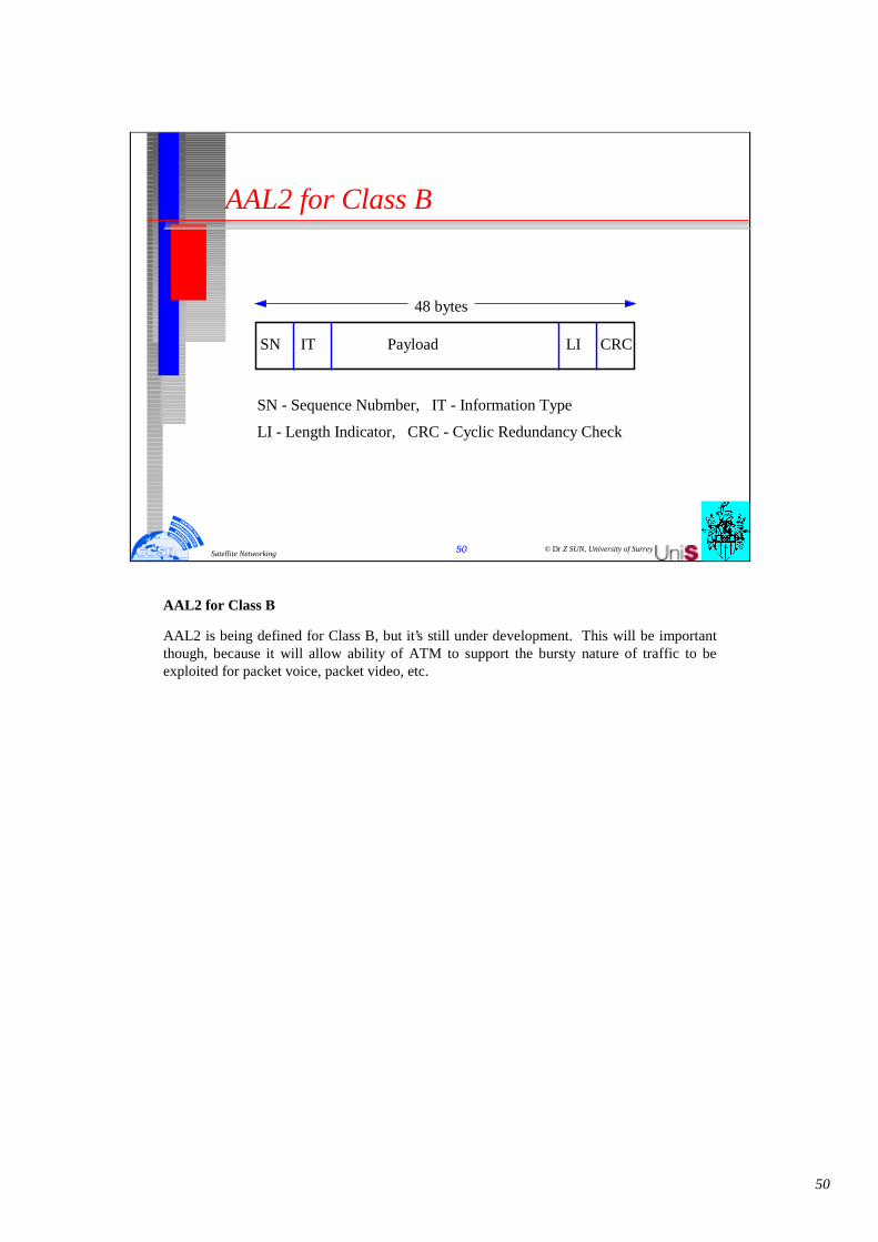
AAL2 for Class B
PayloadIT
48 bytes
SN CRCLI
SN - Sequence Nubmber, IT - Information Type
LI - Length Indicator, CRC - Cyclic Redundancy Check
AAL2 for Class B
AAL2 is being defined for Class B, but it’s still under development. This will be important though, because it will allow ability of ATM to support the bursty nature of traffic to be exploited for packet voice, packet video, etc.

51
© Dr Z SUN, University of Surrey51Satellite Networking
AAL3/4 for Class C&D
44 bytes of data per cellCyclic Redundancy Check (CRC) per cellMessage Identifier (MID) allows muitipleinterleaved packets on a virtual connection
MID CRC
ErrorChecking
User Data
2 2
4
44
Data
ErrorChecking
4 or 8 bytes
0 - 65535 bytes
MID CRC User Data
2 244
MID CRCUser Data
2 244
PAD
AAL 3/4 for Classes C & D
In AAL 3/4, the protocol first puts error-checking functions before and after the original data. Then the information is chopped into 44-byte chunks. The cell payloads include two bytes of header and two bytes of trailer, so this whole construct is exactly 48 bytes.
Notice that there is a CRC check on each cell to check for bit errors.
There is also an MID (Message ID). The MID allows multiplexing and interleaving large packets on a single virtual channel. This is useful in a context where the cost of a connection was very expensive since it would help to guarantee high utilisation of that connection.

52
© Dr Z SUN, University of Surrey52Satellite Networking
AAL5 for Class C&D
48 bytes of data per cellUse PTI bit to indicate last cellOnly one packet at a time on a virtual connection
0 User Data
48
Data
0 - 65535 bytes
0 User Data
48
148
PAD
Last cell flag
0-47
0 LEN
CRC
2 2 4 bytes
Error Detection Fields
AAL5 for Classes C & D
The other data-oriented adaptation layer is AAL5. Here, the CRC is appended to the end and the padding is such that this whole construct is exactly an integral number of 48-byte chunks. This fits exactly into an integral number of cells, so the construct is broken up into 48-byte chunks and put into cells.
To determine when to reassemble and when to stop reassembling, remember the spare bit for PT that was in the header. This bit is zero except for the last cell in the packet (when it is one).
A receiver reassembles the cells by looking at the VPI-VCI and, for a given VPI-VCI, reassembling them into the larger packet. This means that a single VPI-VCI may support only one large packet at a time. Multiple conversations may not be interleaved on a given connection. This is attractive where connections are cheap.

53
© Dr Z SUN, University of Surrey53Satellite Networking
ATM Networks and Interfaces
ATMSwitch
ATMSwitch
PrivateUNI
Terminal
Terminal
ATMSwitch
ATMSwitch
ATMSwitch
PublicNNI
MetropolisData ServiceInc.
ATMSwitch
ATMSwitch
ATMSwitch
PublicNNI
CountryWide CarrierServices
Terminal
Terminal
ATMDXI
PublicUNI
B-ICI
PrivateNNI
Other ATM Interfaces
In the above figure, first consider the private ATM network in the upper left corner. The interface between the terminal and the switch is referred to as the private User-to-Network Interface (UNI). The interface to the public network is a public UNI. Now, these two interfaces are quite similar. For example, the cell size is the same; the cell format is the same. There are some differences, though. For example, the Public UNI interface is likely to be a DS3 interface early on, but it’s very unlikely that one would deploy a DS3 across the campus. Consequently, we’ll probably see some differences at the physical layer.
Within a private ATM network, there is the issue of connecting multiple switches together into an ATM network. This is referred to as the Network Node Interface (NNI). In some ways, the NNI is misnamed because it’s really more than an interface. It is a protocol that allows multiple devices to be interconnected in somewhat arbitrary topologies and still work as one single network.
There’s a corresponding protocol in the public arena called the public NNI. It has basically the same function, but, because of the context of the problem that’s being addressed, it ends up in detail to be quite different.
The private NNI protocol is being specified by The ATM Forum and the public NNI is being specified by ITU. One of the major differences is that in the case of the public NNI, there’s going to be a strong dependence on the signalling network.
The B-ICI specifies how two carriers can use ATM technology to multiplex multiple services onto one link, thereby exchanging information and co-operating to offer services. This is discussed in more detail in a later section.

54
© Dr Z SUN, University of Surrey54Satellite Networking
ATM Networks and Interfaces (cont.)
� Public and private networks� User network interface (UNI)� Network node interface (NNI)� ATM DXI� B-ICI
ATM DXIThe ATM Data Exchange Interface (DXI) allows a piece of existing equipment -- in this case, a router -- to access the ATM network without having to make a hardware change. The hardware impact is in a separate Channel Service Unit / Data Service Unit (CSU/DSU). Typical physical layers for the DXI are like V35 or high-speed serial interface (HSSI). Since this is a data-oriented interface, the frames are carried in HDLC frames. All that is required is a software change in the router and the CSU-DSU to perform the "slicing" segmentation and reassembly (SAR) function. The CSU-DSU takes the frames, chops them up into cells, does traffic shaping if it’s required to abide by the traffic contract, and ends up with a UNI.NNIThe difference in the header at the NNI, as compared with the UNI, is found in the first four bits. Instead of being a GFC field, they have been dedicated to the virtual path identifier, extending it to 12 bits. For a connection between two switches, the total number of virtual path connections goes up by a factor of 16, making this a very large number. This is most desirable at places in the network where a lot of connections go over one physical path.The NNI also provides some other functions, like distribution of topology information. Also, in the case of network failure, the switches in the network need to know that the failure happened, which connections have broken, and which ones need to be re-established.B-ICIThe Broadband Inter-Carrier Interface (B-ICI), in its initial version, is a multiplexing technique. It specifies how two carriers can use ATM technology to multiplex multiple services onto one link, thereby exchanging information and co-operating to offer services. The services specified in the B-ICI are: cell relay service, a circuit emulation service, frame relay, and SMDS.Users of the carrier network don’t "see" this interface, but it is important because it will help provide services across carriers.

55
© Dr Z SUN, University of Surrey55Satellite Networking
ATM over satellite
ATMSwitch
ATMSwitch
ATMSwitch
PublicNNI
Public Network
ATMSwitch
ATMSwitch
ATMSwitch
PublicNNI
Public Network
B-ICIATMSwitch
ATMSwitch
PrivateUNI
Terminal
PublicUNI
P rivateNNI
ATM
Switch
ATM
Switch
ATM
Switch
Public
NNI
PublicNetwork
The reference models have been developed in the context of Wireless ATM within the ATM forum. There address the development of implementation requirements necessary to support the Radio Access Layer of the Wireless ATM (WATM) specification as applicable to ATM access over Geosynchronous satellite link.
It has been recognised that it is important to include the class of applications involving long the geostationary satellite link.
Satellite communication systems are essential components of the Information Infrastructure. The unique operating environment of the satellite communications leads to a number of major challenges in its ability to provide broadband (ATM) services. These challenges stem from the fundamental differences in the satellite and fiber environments and that the ATM and data communications protocols are designed for fiber optic cable infrastructure.
Satellite communication links will be the predominant method of spanning the large distances from information source to destination. At times, satellite links are the only available means to deliver information effectively.
In the commercial arena the need to provide broadband services over satellite is expected to increase significantly. Examples of currently identified applications include linking remote office sites (e.g. oil rigs) to the enterprise backbone and providing broadband entertainment services to mobile platforms (e.g. airplanes, ships. Other examples include disaster relief (e.g. FEMA operation) scenarios and remote/rural medical care where the infrastructure is either disrupted or lacking.

56
© Dr Z SUN, University of Surrey56Satellite Networking
ATM Forum Scenarios
Major work items identified for consideration by the WATM working group.
(A) "Radio access layer" protocols including (but not limited to):A.1 Radio physical layer. A.2 Medium access control for wireless channel (with QoS, etc.).A.3 Data link control for wireless channel errors.A.4 Wireless control protocol for radio resource management.
(B) "Mobile ATM" protocol extensions including (but not limited to):B.1 Handoff control (signaling/NNI extensions, etc.)B.2 Location management for mobile terminalsB.3 Routing considerations for mobile connections.B.4 Traffic/QoS control for mobile connections.B.5 Wireless Network Management
For a geostationary satellite link to conform to the new WATM System Reference Model, the fixed network will interface with a WATM radio port through the “W”NNI, which will provide a duplex link to a geostationary communications satellite. The “W”NNI is the union of the “M”NNI and the “R”RAL interface. Two different modes of satellite implementation are under study. In the first mode the satellite acts as a relay or “bent-pipe” between two switching end points. In the second mode the satellite acts as a switching point within the network and is interconnected with more than two terrestrial network end-points.
The interoperability problems between satellite and terrestrial networks manifest themselves mainly in four ways: (a) Errors, (b) Delay, (c) Bandwidth Limitation and (d) Availability.
Errors: The satellite RF links in certain circumstances operate with higher bit error rates than fiber optic links and satellite links with forward error correction will have bursty errors with variable error rate as opposed to random errors on fiber links. An example of the lack of compatibility is that ATM operation is intolerant to burst errors. Also, ATM Quality of Service requirements for multimedia applications appear to be more stringent than what the application requires and so impose an unnecessary cost penalty on networks with satellite links.
Delay: The round trip propagation delay of around 0.54 seconds, which is intrinsic to thegeosynchronous satellite communication, can have an adverse impact on the performance of ATM traffic and congestion control procedures and transport protocol operation.

57
© Dr Z SUN, University of Surrey57Satellite Networking
Reference Model for ‘W’UNI to ‘M’NNI usage via ATM Switch enabled Satellite
Radio Access Segment Fixed Network SegmentRadio Access SegmentSatelliteSegment
MobilityEnabledATMSwitch
ATMNetwork
ATMHost
WATMRadio Port
WATMTerminal
WATMTA
WATMRadioPort
Satellite-Based
M.E.Switch
WATMRadioPort
MobilityEnabledATMSwitch
WATM‘R’ RAL
ATMNNI
ATMUNI
ATM‘M’NNI
ATM‘W’ UNI
WATM‘R’ RAL
ATM‘W’NNI
User Process
AAL
ATM
WATM
RAL
User Process
AAL
ATM
ATM
PHY
ATM
ATM ATM
PHY PHYU-PLANE
ATM
WATM ATM
RAL PHY
ATM
WATM WATM
RAL RAL
ATM
ATM ATM
PHY PHY
C-PLANE
W-CTL
W-CTL
SIG,NNI + M
SAAL
ATM
ATM ATM
RAL RAL
SIG, UNI
SAAL
ATM
ATM PHY
SIG,NNI
SAAL
ATM
ATM ATM
PHY PHY
SIG,NNI + M
SAAL
ATM
WATM ATM
RAL PHY
W-CTL
SIG,NNI + M
SAAL
ATM
ATM ATM
PHY PHY
SIG, UNI
SAAL
ATM
WATM RAL
W-CTL
Bandwidth: Satellite communication bandwidth being a limited resource will continue to be a precious asset and is at odds with bandwidth inefficient ATM protocols. For example, ATM Constant Bit Rate (CBR) Speech will require a satellite bearer channel exceeding 70 kbps for carrying one voice channel at a penalty of at least twice the bandwidth needed to run the application.
Availability: At the higher frequency bands that are being investigated for satellite delivery of ATM, achieving availability rates of 99.95% at required BERs is costly. Yet lowering required availability rates by even .05% dramatically lowers satellite link costs. An optimum availability level must be a compromise between cost and performance.

58
© Dr Z SUN, University of Surrey58Satellite Networking
Reference Model for ‘M’NNI to ‘M’NNI usage via ATM Switch enabled Satellite
Radio Access Segment Fixed Network SegmentRadio Access Segment Satellite SegmentMobile Multi-User Platform
WATM‘R’ RAL
WATM‘R’ RAL
WATMRadioPort
Satellite-Based
M.E.Switch
WATMRadioPort
ATM‘W’NNI
ATMNNI
ATMUNI
MobilityEnabledATMSwitch
WATMRadio Port
ATMNetwork
ATMHost
ATMNNI
ATMUNI
ATM‘M’NNI
MobilityEnabledATMSwitch
ATMNetwork
ATMHost
WATMRadio Port
MobilityEnabledATMSwitch
ATM‘W’NNI
U-PLANE
User Process
AAL
ATM
ATM
PHY
ATM
ATM ATM
PHY PHY
ATM
WATM ATM
RAL PHY
ATM
WATM WATM
RAL RAL
User Process
AAL
ATM
ATM
PHY
ATM
ATM WATM
PHY RAL
ATM
ATM ATM
PHY PHY
ATM
ATM ATM
PHY PHY
C-PLANE
IG, UNI
SAAL
ATM
ATM PHY
SIG,UNI
SAAL
ATM
ATM PHY
SIG,NNI
SAAL
ATM
ATM ATMPHY PHY
SIG,NNI + M
SAAL
ATM
ATM ATMRAL PHY
W-CTL
W-CTL
W-CTL
SIG,NNI + M
SAAL
ATM
WATM WATMRAL RAL
SIG,NNI + M
SAAL
ATM
ATM ATMPHY PHY
SIG,NNI + M
SAAL
ATM
ATM ATMPHY RAL
W-CTL
SIG, NNI
SAAL
ATM
ATM ATMPHY PHY
In order to provide ATM services over satellite without established standards the operators of satellite networks could either live with the current satellite specifications and its resultant inefficiencies, or design additional special signal processing functionality at an added cost and/or performance penalty to the end user. A number of techniques have been studied to overcome many of these problems. A set of specifications, that address the above issues, is needed to standardize high quality, bandwidth efficient ATM operation via satellite and interoperability with its terrestrial counterparts.
As mentioned previously, consideration of geostationary (GEO) satellites does not cover the full spectrum of satellite-based access scenarios. GEO satellites have coverage areas spanning thousands of miles thus eliminating the need for call hand-off and minimizing (or eliminating) the need for antenna tracking. However, the scenario involving Low Earth Orbit (LEO) satellites will have to address these issues in addition to the issues pertinent to the GEO case. Investigation of point-to-point links via GEO satellites is an appropriate starting point for the satellite based WATM specification because of the near-term market need for this class of satellite networks.

59
© Dr Z SUN, University of Surrey59Satellite Networking
Reference Model for ‘W’UNI to ‘M’NNI usage via Relay Satellite
Radio Access Segment Fixed Network SegmentRadio Access SegmentSatellite Segment
WATM‘R’ RAL
ATMNNI
ATMUNI
ATM‘M’NNI
ATM‘W’ UNI
WATM‘R’ RAL
MobilityEnabledATMSwitch
ATMNetwork
ATMHost
WATMRadio Port
WATMTerminal
WATMTA
RelaySatellite
WATMRadio Port
WATMRadio Port
User Process
AAL
ATM
WATM
RAL
User Process
AAL
ATM
ATM
PHY
ATM
ATM ATM
PHY PHYU-PLANE
ATM
WATM ATM
RAL PHY
ATM
ATM ATM
PHY PHY
WATM WATM
RAL RAL
C-PLANE
SIG, UNI
AAL
ATM
WATM RAL
SIG, UNI
AAL
ATM
ATM PHY
SIG,NNI
SAAL
ATM
ATM ATM
PHY PHY
W-CTL
SIG,NNI + M
SAAL
ATM
ATM ATM
RAL PHY
W-CTL
SIG,NNI + M
SAAL
ATM
ATM ATM
PHY PHY
WATM WATM
RAL RAL
Radio Access Layer•Radio Physical Layer: The RAL layer for satellite access must take into account the performance requirements for GEO satellites. A frequency independent specification is preferred. Parameters to be specified include range, bit rates, transmit power. modulation/coding, framing formats, and encryption. Techniques for dynamically adjusting to varying link conditions and coding techniques for achieving maximum bandwidth efficiencies need to be considered.•Medium Access Control: The MAC protocol is required to support the shared use of the satellite channel by multiple switching nodes. A primary requirement for the MAC protocol is to ensure bandwidth provisioning for all the traffic classes as identified in UNI 4.0. The protocol should satisfy both the fairness and efficiency criteria.•Data Link Control: The DLC layer is responsible for the reliable delivery of ATM cells across the GEO satellite link. Since higher layer performance is extremely sensitive to cell loss, error control procedures need to be implemented. Special cases for operation over simplex (or highly bandwidth asymmetric) links needs to be developed. DLC algorithms tailored to special specific QoS classes will be considered.
•Wireless Control: Wireless control is needed for support of control plane functions related to resource control and management of the PHY, MAC, and DLC layers specific to establishing a wireless link over GEO satellite. This would also include metasignaling for mobility support.

60
© Dr Z SUN, University of Surrey60Satellite Networking
Reference Model for ‘M’NNI to ‘M’NNI usage via Relay Satellite
Radio Access Segment Fixed Network SegmentRadio Access Segment Satellite SegmentMobile Multi-UserPlatform
WATM‘R’ RAL
WATM‘R’ RAL
ATMNNI
ATMUNI
ATM‘M’NNI
ATM‘M’NNI
ATMNNI
ATMUNI
MobilityEnabledATMSwitch
ATMNetwork
ATMHost
WATMRadio Port
MobilityEnabledATMSwitch
WATMRadio Port
ATMNetwork
ATMHost
RelaySatellite
WATMRadio Port
WATM Radio Port
U-PLANE
User Process
AAL
ATM
ATM
PHY
AT
ATM
PHY
ATM
WATM ATM
RAL
AT
ATM
PHY PHY
User Process
AAL
ATM
WAT
PHY
ATM
ATM
PHY RAL
AT
ATM
PHY PHY
WATM
RAL
C-
User Process
AAL
ATM
ATM
SIG, UNI
AAL
ATM
ATM PHY
SIG,NNI
SAAL
ATM
ATMPHY
SIG,NNI + M
SAAL
AT
ATMRAL
W-CTL
SIG,NNI + M
SAAL
AT
ATMPHY PHY
SIG,NNI + M
SAAL
ATM
ATM ATMPHY RAL
WCTL
SIG, NNI
SAAL
AT
ATMPHY PHY
WATM
RAL RAL
Mobile ATM•Hand-off control: Hand-off is a basic mobile network capability that allows for the migration of a node across the network backbone without dropping an ongoing call. Because of the geographical distances involved, hand-off for access over GEO satellite is expected not to be an issue in most applications. In some instances, for example intercontinental flights, a slow hand-off between GEO satellites with overlapping coverage areas will be required. To support this, an extension of the PNNI signaling specifications for rerouting an ongoing call needs to be implemented.•Location Management: Location management refers to the capability of one-to-one mapping a mobile nodes ‘name’ and current ‘routing-id.’ Location management primarily applies to the scenario involving switching on board the satellite, where the issues are relevant to Wireless P-NNI.
Work items for further reasearch:Requirements for Radio Access Layer and Mobile ATM functions for ATM over satellite pertinent to both the ‘bent-pipe’ and ‘switching’ scenarios.
The impact of a geostationary satellite delay on the traffic management and congestion control procedures defined in the ATM Forum TM 4.0 Specification, and upper layer protocols such as TCP, and to develop specifications of additional algorithms (if needed) for ATM operation over satellite.
Requirements and specifications for bandwidth efficient operation of ATM speech over a satellite link.
ATM scenarios and corresponding requirements for satellite using simplex (or highly bandwidth asymmetric) links.
Frequency spectrum availability issues.

61
© Dr Z SUN, University of Surrey61Satellite Networking
Internet over satellite

62
© Dr Z SUN, University of Surrey62Satellite Networking
Protocol reference architectures
PLATM
TDMA
Satellite ATM Architecture
AAL
Services & Applications
PLEther FDDI DQDB ATM
IP (Internetwork)TCP UDP
XDR
RPC
YPftp, mail , rcp, rlogin , rsh, telnet , talk, name
voice , video , multimedia
Existing Network Architecture
PL PL PL
NFS
Satellite
Note. For details about TCP/IP, refer the TCP/IP section.
The SatelliteNearly all commercial communication satellites are geostationary. Such satellites orbit the earth in a 24-hr period. Thus they appear stationary over a particular geographic location on earth. For a 24-hr synchronous orbit the altitude of a geostationary satellite is 22,300 statute miles or 35,900 km above the earth’s equator.
Most of the presently employed communication satellites are RF repeaters. A typical RF repeater used in a communication satellite. The tendency today is to call these types of satellite "bent pipe" satellites as opposed to processing satellites. A processing satellite, as a minimum, regenerates the received digital signal. It may decode and recode a digital bit stream. It also may have some bulk switching capability, switching to crosslinks connecting to other satellites. Theoretically, as mentioned earlier, three such satellites placed correctly in equatorial geostationary orbit could provide communication from one earth station to anyother located anywhere on the earth surface. However, high latitude service is marginal and nil north of 80 North and south of 80 South.
Three Basic Technical Problems
Satellite communication is nothing more than radiolink (microwave LOS) communication using one or two RF repeaters located at great distances from the terminal earth stations.
We thus are dealing with very long distances. The time required to traverse these distances -- namely, earth station to satellite to another earth station -- is on the order of 250 ms. Round-trip delay will be 2 x 250 or 500 ms. These propagation times are much greater than those encountered on conventional terrestrial systems. So one major problem is propagation time and resulting echo on telephone circuits. It influences certain data circuits in delay to reply for block or packet transmission systems and requires careful selection of telephone signaling systems, or call-setup time may become excessive.

63
© Dr Z SUN, University of Surrey63Satellite Networking
IP Throughput Issues
Version Header Len. Type of service
Total length
D M Fragment offset
Time-to-live Protocol
Header checksum
Identification
Source address
Destination address
Options
Data(<=65536 octets)
Bit order1 16
Hea
der
IP Throughput IssuesIP (the Internet Protocol) is the network layer protocol in the TCP/IP protocol suite. IP’s function is to provide a protocol to integrate heterogeneous networks together. In brief, a media-specific way to encapsulate IPdatagrams is defined for each media (e.g., satellite, Ethernet, or Asynchronous Transfer Mode). Devices called routers move IP datagramsbetween the different media and their encapsulations. Routers pass IPdatagrams between different media according to routing information in the IPdatagram. This mesh of different media interconnected by routers forms an IP Internet, in which all hosts on the integrated mesh can communicate with each other using IP.
The actual service IP implements is unreliable datagram delivery. IP simply promises to make a reasonable effort to deliver every datagram to its destination. However IP is free to occasionally lose datagrams, deliverdatagrams with errors in them, and duplicate and reorder datagrams.
Because IP provides such a simple service, one might assume that IP places no limits on throughput. Broadly speaking, this assumption is correct. IP places no constraints on how fast a system can generate or receive datagrams. A system transmits IP datagrams as fast as it can generate them. However, IP does have two features that can affect through-put: the IP Time to Live and IP Fragmentation.

64
© Dr Z SUN, University of Surrey64Satellite Networking
Time to live (8 bits, about 4.26 minutes)
� The field is decremented at least once at every router thedatagram encounters and when the TTL reaches zero, thedatagram is discarded.
� Specifications for higher layer protocols like TCP usually assume that the maximum time a datagram can live in the network is only two minutes.
� The significance of the maximum datagram lifetime is that it means higher layer protocols must be careful not to send two similar datagrams within a few minutes of each other.
� This limitation is particularly important for sequence numbers.
IP Time To Live - In certain situations, IP datagrams may loop among a set of routers. These loops are sometimes transient (a datagram may loop for a while and then proceed to its destination) or long-lived. To protect againstdatagrams circulating semipermanently, IP places a limit on how long adatagram may live in the network.
The limit is imposed by a Time To Live (TTL) field in the IP datagram. The field is decremented at least once at every router the datagram encounters and when the TTL reaches zero, the datagram is discarded.Originally, the IP specification also required that the TTL also be decremented at least once per second. Since the TTL field is 8-bits wide, this means a datagram could live for approximately 4.25 minutes. In practice, the injunction to decrement the TTL once a second is ignored, but, perversely, specifications for higher layer protocols like TCP usually assume that the maximum time a datagram can live in the network is only two minutes.The significance of the maximum datagram lifetime is that it means higher layer protocols must be careful not to send two similar datagrams (in particular, two datagrams which could be confused for each other) within a few minutes of each other. This limitation is particularly important for sequence numbers. If a higher layer protocol numbers its datagrams, it must ensure that it does not generate two datagrams with the same sequence number within a few minutes of each other, lest IP deliver the seconddatagram first and confuse the receiver. We discuss this issue more in the next section when we discuss TCP sequence space issues.

65
© Dr Z SUN, University of Surrey65Satellite Networking
IP Fragmentation
� Different network media have different limits on the maximum datagram - Maximum Transmission Unit (MTU).
� IP supports fragmentation and reassembly� Fragments are identified using a fragment offset field .� Datagrams are uniquely identified by their source,
destination, higher layer protocol type, and a 16 bit IP identifier.
� there’s a clear link between the TTL field and the IP identifier
� MTU Discovery is a mechanism that allows hosts to determine the MTU of a path reliably.
IP Fragmentation - Different network media have different limits on the maximum datagramsize. This limit is typically referred to as the Maximum Transmission Unit (MTU). When a router is moving a datagram from one media to another, it may discover that the datagram, which was of legal size on the inbound media, is too big for the outbound media. To get around this problem, IP supports fragmentation and reassembly, in which a router can break the datagram up into smaller datagrams to fit on the outbound media. The smaller datagramsare reassembled into the original larger datagram at the destination (not the intermediate hops).
Fragments are identified using a fragment offset field (which indicates the offset of the fragment from the start of the original datagram). Datagrams are uniquely identified by their source, destination, higher layer protocol type, and a 16bit IP identifier (which must be unique when combined with the source, destination and protocol type).
Observe that there’s a clear link between the TTL field and the IP identifier. An IP source must ensure that it does not send two datagrams with the same IP identifier to the same destination, using the same protocol within a maximum datagram lifetime, or fragments of two different datagrams may be incorrectly combined. Since the IP identifier is only 16 bits, if the maximum datagram lifetime is two minutes, we are limited to a transmission rate of only 546 datagrams per second. That’s clearly not fast enough. The maximum IP datagramsize is 64 KB, so 546 datagrams is, at best, a bit less than 300 Mb/s.
The problem of worrying about IP identifier consumption has largely been solved by the development of MTU Discovery a technique for IP sources to discover the MTU of the path to a destination. MTU Discovery is a mechanism that allows hosts to determine the MTU of a path reliably. The existence of MTU discovery allows hosts to set the Don’t Fragment (DF) bit in the IP header, to prohibit fragmentation, because the hosts will learn through MTU discovery if their datagrams are too big. Sources that set the DF bit need not worry about the possibility of having two identifiers active at the same time. Systems that do not implement MTU discovery (and thus cannot set the DF bit) need to be careful about this problem.

66
© Dr Z SUN, University of Surrey66Satellite Networking
TCP Segment Header
Data offset Reserved Flags
Urgent pointer
Header checksum
Sequence number
Options & Padding
Data Size (Optional)
Bit order1 16
Hea
der
Source port
Destination port
Acknowledgment number
Window size
TCP Throughput Issues
The Transmission Control Protocol (TCP) is the primary transport protocol in the TCP/IP protocol suite. It implements a reliable byte stream over the unreliable datagram service provided by IP. As part of implementing the reliable service, TCP is also responsible for flow and congestion control: ensuring that data is transmitted at a rate consistent with the capacities of both the receiver and the intermediate links in the network path. Since there may be multiple TCP connections active in a link, TCP is also responsible for ensuring that a link’s capacity is responsibly shared among the connections using it. As a result, most throughput issues are rooted in TCP.
Many of these performance issues have been discovered over the past few years as link transmission speeds have increased and so called high delay-bandwidth path (paths where the product of the path delay and available path bandwidth is big) have become common. In the 1970s, the typical long link was a 56 kb/s circuit across the United States, with a delay-bandwidth product of approximately 0.250 x 56,000 bits or 1.8 KB.

67
© Dr Z SUN, University of Surrey67Satellite Networking
Throughput Expectations
� TCP throughput determines how fast most applications can move data across a network. such as HTTP, FTP
� TCP performance directly impacts application performance.
� No formal TCP performance standards� A TCP connection should be able to fill the available
bandwidth of a path and to share the bandwidth with other users.
Throughput Expectations
TCP throughput determines how fast most applications can move data across a network. Application Protocol such as HTTP (the World Wide Web protocol), and the File Transfer Protocol (FTP), rely on TCP to carry their data. So TCP performance directly impacts application performance.
While there are no formal TCP performance standards, TCP expertsgenerally expect that, when sending large datagrams (to minimize the overhead of the TCP and IP headers), a TCP connection should be able to fill the available bandwidth of a path and to share the bandwidth with other users. If a link is otherwise idle, a TCP connection is expected to be able to fill it. If a link is shared with three other users, we expect each TCP to get a reasonable share of the bandwidth.
These expectations reflect a mix of practical concerns. When users of TCP acquire faster data lines, they expect their TCP transfers to run faster. And users acquire faster lines for different reasons. Some need faster lines because as their aggregate traffic has increased, they have more applications that need network access. Others have a particular application that requires more bandwidth. The requirement that TCP share a link effectively reflects the needs of aggregation; all users of a faster link should see improvement. The requirement that TCP fill an otherwise idle link reflects the needs of more specialized applications.

68
© Dr Z SUN, University of Surrey68Satellite Networking
TCP Sequence Numbers
� TCP keeps track of all data in transit by assigning each byte a unique sequence number. The receiver acknowledges received data up to a particular byte number.
� TCP allocates its sequence numbers from a 32-bit wraparound sequence space.
� For a given sequence number uniquely identifies a particular byte, TCP requires that no two bytes with the same sequence number be active at the same time.
� Timestamps using an algorithm called PAWS (Protection Against Wrapped Sequence numbers) to distinguish between two identical sequence numbers sent less than two minutes apart.
TCP Sequence NumbersTCP keeps track of all data in transit by assigning each byte a unique sequence number. The receiver acknowledges received data by sending an acknowledgment which indicates that the receiver has received all data up to a particular byte number.TCP allocates its sequence numbers from a 32-bit wraparound sequence space. To ensure that a given sequence number uniquely identifies a particular byte, TCP requires that no two bytes with the same sequence number be active in the network at the same time. Recall the early discussion of IP datagram lifetime indicated a datagram was assumed to live for up to two minutes. Thus when TCP sends a byte in an IP datagram, the sequence number of that byte cannot be reused for two minutes. Unfortunately, a 32-bit sequence space spread over two minutes gives a maximum data rate of only 286 Mb/s.To fix this problem, the Internet End-to-End Research Group devised a set of TCP options and algorithms to extend the sequence space. These changes were adopted by the Internet Engineering Task Force (IETF) and are now part of the TCP standard. The option is a timestamp option which concatenates a timestamp to the 32-bit sequence number. Comparing timestamps using an algorithm called PAWS (Protection Against Wrapped Sequence numbers) makes it possible to distinguish between two identical sequence numbers sent less than two minutes apart.Depending on the actual granularity of the timestamp (the IETF recommends between 1 second and I millisecond), this extension is sufficient for link speeds of between 8 Gb/s and 8 Tb/s (terabits per second).

69
© Dr Z SUN, University of Surrey69Satellite Networking
TCP Transmission Window
� To allow the receiving TCP to control how much data is being sent, by advertising a window size to the sender.
� The window measures, in bytes, the amount of unacknowledged data that the sender can have in transit .
� The distinction between the sequence numbers and the window is that sequence numbers are designed to allow the sender to keep track of the data in flight, while the window is to allow the receiver to control the receiving rate.
� The standard TCP window size cannot exceed 64 KB, with the window of 16 bits wide.
� IETF enhanced TCP to negotiate a window scaling option.
TCP Transmission Window
The purpose of the transmission window is to allow the receiving TCP to control how much data is being sent to it at any given time. The receiver advertises a window size to the sender. The window measures, in bytes, the amount of unacknowledged data that the sender can have in transit to the receiver. The distinction between the sequence numbers and the window is that sequence numbers are designed to allow the sender to keep track of the data in flight, while the window’s purpose is to allow the receiver to control the rate at which it receives data.
Obviously, if a receiver advertises a small window (due, perhaps, to buffer limitations) it is impossible for TCP to achieve high transmission rates. And many implementations do not offer a very large window size (a few kilobytes is typical).
However, there is a more serious problem. The standard TCP window size cannot exceed 64 KB, because the field in the TCP header used to advertise the window is only 16 bits wide. This limits the TCP effective bandwidth to 2E16 bytes divided by the round-trip time of the path. For long delay links, such as those through satellites with a geosynchronous orbit (GEO), this limit gives a maximum data rate of just under 1 Mb/s.
As part of the changes to add timestamps to the sequence numbers, the End-To-End Research Group and IETF also enhanced TCP to negotiate a window scaling option. The option multiplies the value in the window field by a constant. The effect is that the window can only be adjusted in units of the multiplier. So if the multiplier is 4, an increase of 1 in the advertised window means the receiver is opening the window by 4 bytes.
The window size is limited by the sequence space (the window must be no larger than one half of the sequence space so that it is unambiguously clear that a byte is inside or outside the window). So the maximum multiplier permitted is 2E14. This means the maximum window size is 2x10E30 and the maximum date rate over a GEO satellite link is approximately 15Gb/s. Given we have achieved Tb/s data rates in terrestrial fiber, this value is depressingly small, but in the absence of a major change to the TCP header format it is not clear how to fix the problem.

70
© Dr Z SUN, University of Surrey70Satellite Networking
Slow Start Algorithm
44 40 36 32 28 24 201612840
0 2 4 6 8 10 12 14 16 18 20 22 24
Timeout
Threshold
Threshold
Slow Start - When a TCP connection starts up, the TCP specification requires the connection to be conservative and assume that the available bandwidth to the receiver is small. TCP is supposed to use an algorithm called slow start to probe the path to learn how much bandwidth is available.
The slow start algorithm is quite simple and based on data sent per round trip. At the start, the sending TCP sends one TCP segment (datagram) and waits for an acknowledgment. When it gets the acknowledgment, it sends two segments. Many TCPs acknowledge every one segment they receive, so the slow start algorithm effectively sends 100 percent more data every round trip. It continues this process (sending 50 percent more data each round trip) until a segment is lost. This loss is interpreted as indicating congestion and the connection scales back to a more conservative approach (described in the next section) for probing bandwidth for the rest of the connection.
There are two problems with the slow start algorithm on high-speed networks. First, the probing algorithm can take a long time to get up to speed. The time required to get up to speed is R(l + log2 (DB/L)), where R is the round-trip time, DB is the delay-bandwidth product and L is the average segment length. If we are trying to fill a pipe with a single TCP connection (and, if the TCP connection is the sole user of the link, filling the link is considered the canonical goal), then DB should be the product of the bandwidth available to the connection and the round-trip time.
An important point is that as the bandwidth goes up or round-trip time increases, or both, thisstartup time can be quite long. For instance, on a Gb/s GEO satellite link with a 0.5 second round-trip time, it takes 29 round-trip times or 14.5 seconds to finish startup. If the link is otherwise idle, during that period most of the link bandwidth will be unused (wasted).

71
© Dr Z SUN, University of Surrey71Satellite Networking
Slow Start Algorithm (continue)
� The slow start algorithm is based on data sent per round trip. � This loss is interpreted as indicating congestion and the
connection scales back to a more conservative approach.� There are two problems
• The probing algorithm can take a long time to get up to speed. The time is R(1 + log2 (DB/L)) , where, R: round trip time, DB: delay bandwidth product, L: average segment size.
• The second problem is interpreting loss as indicating congestion.
� There is no easy way to distinguish losses due to transmission errors from losses due to congestion (assuming that all losses are due to congestion.)
Even worse is that, in many cases, the entire transfer will complete before the slow start algorithm has finished. The user will never experience the full link bandwidth. All the transfer time will be spent in slow start. This problem is particularly severe for HTTP (the World Wide Web protocol), which is notorious for starting a new TCP connection for every item on a page. This poor protocol design is a (major) reason Web performance on the Internet is perceived as poor: the Web protocols never let TCP get up to full speed.
The IETF is in the early stages of considering a change to allow TCPs to transmit more than one segment (the current proposal permits between two and four segments) at the beginning of the initial slow start. If there is capacity in the path, this change will reduce the slow start by up to three round-trip times. This change mostly benefits shorter transfers that never get out of slow start.
The second problem is interpreting loss as indicating congestion. TCP has no easy way to distinguish losses due to transmission errors from losses due to congestion, so it makes the conservative assumption that all losses are due to congestion.

72
© Dr Z SUN, University of Surrey72Satellite Networking
Congestion Avoidance
� The sending TCP maintains a congestion window � Every round trip, the sending TCP increases its estimate of
the available bandwidth by one maximum-sized segment. Whenever the sender either finds a segment was lost or receives an indication from the network (e.g., an ICMP Source Quench) that congestion exists, the sender halves its estimate of the available bandwidth.
� The major issue with this algorithm is that over high-delay-bandwidth links and the linear probing algorithm
� Another issue is that the rate of improvement under congestion avoidance is a function of the delay-bandwidth product.
Congestion Avoidance
Throughout a TCP connection, TCP runs a congestion avoidance algorithm which is similar to the slow start algorithm. Essentially, the sending TCP maintains a congestion window, an estimate of the actual available bandwidth of the path to the receiver. This estimate is set initially by the slow start at the start of the connection. Then the estimate is varied up and down during the life of the connection based on indications of congestion (or the absence thereof). In general, congestion is assumed to be indicated by loss of one or more datagrams.
The basic estimation algorithm is as follows. Every round trip, the sending TCP increases its estimate of the available bandwidth by one maximum-sized segment. Whenever the sender either finds a segment was lost (conservatively assumed to be due to congestion) or receives an indication from the network (e.g., an ICMP Source Quench) that congestion exists, the sender halves its estimate of the available bandwidth. The sender then resumes the one segment per round-trip probing algorithm. (In certain, extreme, loss situations, the sender will do a slow start).
Like the slow start algorithm, the major issue with this algorithm is that over high-delay-bandwidth links, a datagram lost to transmission error will trigger a low estimate of the available bandwidth, and the linear probing algorithm will take a long time to recover.
Another issue is that the rate of improvement under congestion avoidance is a function of the delay-bandwidth product. Basically congestion avoidance allows a sender to increase its window by one segment, for every round-trip time’s worth of data sent. In other words, congestion avoidance increases the transmission rate by 1/DB each round trip.

73
© Dr Z SUN, University of Surrey73Satellite Networking
Selective Acknowledgments
� An extension to TCP by IETF� SACKs have two major benefits.
• improve the efficiency of TCP retransmissions by reducing the retransmission period.
• better evaluate the available path bandwidth in a period of successive losses and avoid doing a slow start.
� Inter-Relations - It is important to keep in mind that all the various TCP mechanisms are interrelated• the sequence space, window size, ... • More broadly, tinkering with TCP algorithms tends to
show odd interrelations.
Selective Acknowledgments
Recently the Internet Engineering Task Force has approved an extension to TCP called Selective Acknowledgments (SACKS). SACKs make it possible for TCP to acknowledge data received out of order. Previously TCP had only been able to acknowledge data received in order.
SACKs have two major benefits. First, they improve the efficiency of TCP retransmissions by reducing the retransmission period. Historically, TCP has used a retransmission algorithm that emulates selective-repeat ARQ using the information provided by in-order acknowledgments. This algorithm works, but takes roughly one round-trip time per lost segment to recover. SACK allows a TCP to retransmit multiple missing segments in a round trip. Second, and more importantly, it has been shown that with SACKs a TCP can better evaluate the available path bandwidth in a period of successive losses and avoid doing a slow start.
Inter-Relations - It is important to keep in mind that all the various TCP mechanisms are interrelated, especially when applied to problems of high performance. If the sequence space and window size are not large enough, no improvement to congestion windows will help, since TCP cannot go fast enough anyway. Also, if the receiver chooses a small window size, it takes precedence over the congestion window, and can limit throughput.
More broadly, tinkering with TCP algorithms tends to show odd interrelations. For instance, the individual TCP Vegas performance improvements were shown to work only when applied together applying only some of the changes actually degraded performance. And there are also known TCP syndromes where the congestion window gets misestimated, causing the estimation algorithm to briefly thrash before converging on a congestion window. (The best known is a case where a router has too little buffer space, causing bursts of datagrams to be lost even though there is link capacity to carry all the datagrams).

74
Satellites and TCP/IP Throughput
For the rest of this article we apply the general discussion of the previous section to the specific problem of achieving high throughput over satellite links. First, we point out the need to implement the extensions to the TCP sequence space and window size. Then we discuss the relationship between slow start and performance over satellite links and some possible solutions.
Currently satellites offer a range of channel bandwidths, from the very small (a compressed phone circuit of a few kb/s) to the very large (the Advanced Communications and Telecommunications Satellite with 622-Mb/s circuits). They also have a range of delays, from relatively small delays of low earth orbit (LEO) satellites to the much larger delays of GEO satellites. Our concern is making TCP/IP work well over those ranges.
General Performance
Many of the problems described in the previous section on TCP/IP performance were ones that became acute only over high-delay-bandwidth paths. One of the first things to note is that all but the slowest satellite links are, by definition, high delay-bandwidth paths, because the transmission delays to and from the satellite from the Earth’s surface are large.
Table 1 illustrates for a range of common bandwidths, when the TCP enhancements of PAWS and large windows are required to fully utilize the bandwidth on a LAN link with 5 ms one-way delay, a LEO link (100 ms one-way) and GEO (250 ms one-way) link, for a range of link speeds. We also indicate how long slow start takes to get to full link speed, assuming 1 KB datagrams (a typical size) are transmitted and how much data is transferred during the slow start phase.
The table highlights some key challenges for satellites (and also for transcontinental terrestrial links, which have delays similar to LEO satellite links). One simply cannot get a TCP/IP implementation to perform well at higher speeds unless it supports large windows, and at speeds past about 100 Mb/s, PAWS. Thus anyone who has not had their TCP/IP software upgraded with PAWS and large windows will not be able to achieve high performance over a satellite link.
© Dr Z SUN, University of Surrey74Satellite Networking
Satellites and TCP/IP Throughput
� The need to implement the extensions to the TCP sequence space and window size.
� The relationship between slow start and performance over satellite links and some possible solutions.
� Satellites offer a range of channel bandwidths with relatively small delays of LEO and much larger delays of GEO satellites.
� The satellite performance problems are due to high-delay-bandwidth paths.
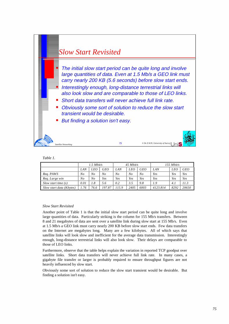
75
© Dr Z SUN, University of Surrey75Satellite Networking
Slow Start Revisited
� The initial slow start period can be quite long and involve large quantities of data. Even at 1.5 Mb/s a GEO link must carry nearly 200 KB (5.6 seconds) before slow start ends.
� Interestingly enough, long-distance terrestrial links will also look slow and are comparable to those of LEO links.
� Short data transfers will never achieve full link rate. � Obviously some sort of solution to reduce the slow start
transient would be desirable. � But finding a solution isn’t easy.
Table 1.
Slow Start Revisited
Another point of Table 1 is that the initial slow start period can be quite long and involve large quantities of data. Particularly striking is the column for 155 Mb/s transfers. Between 8 and 21 megabytes of data are sent over a satellite link during slow start at 155 Mb/s. Even at 1.5 Mb/s a GEO link must carry nearly 200 KB before slow start ends. Few data transfers on the Internet are megabytes long. Many are a few kilobytes. All of which says that satellite links will look slow and inefficient for the average data transmission. Interestingly enough, long-distance terrestrial links will also look slow. Their delays are comparable to those of LEO links.
Furthermore, observe that the table helps explain the variation in reported TCP goodput over satellite links. Short data transfers will never achieve full link rate. In many cases, a gigabyte file transfer or larger is probably required to ensure throughput figures are not heavily influenced by slow start.
Obviously some sort of solution to reduce the slow start transient would be desirable. But finding a solution isn’t easy.
1.5 Mbit/s 45 Mbit/s 155 Mbit/s
LAN LEO GEO LAN LEO GEO LAN LEO GEO
Req. PAWS No No No No No No Yes Yes Yes
Req. Large win No No Yes Yes Yes Yes Yes Yes Yes
Slow start time (s) 0.01 1.8 5.6 0.2 3.5 9.8 1.9 4.1 11.3
Slow start data (Kbytes) 1.76 76.6 197.87 115.9 2405 6003 4123.814 8292 20650

76
One obvious solution is to dispense with slow start and just start sending as fast as one can until data is dropped, and then slow down. This approach is known to be disasterous. Indeed, slow start was invented in an environment in which TCP implementations behaved this way and were driving the Internet into congestion collapse. As one example of how this scheme goes wrong, consider a Gb/s capable TCP launching several 100s of megabits of data over a path that turns out to have only 9.6 kb/s of bandwidth. There’s a tremendous bandwidth mismatch which will cause datagrams to be discarded or suffer long queuing delays.
As this example illustrates, one of the important problems is that a sending TCP has no idea, when it starts sending, how much bandwidth a particular transmission path has. In the absence of knowledge, a TCP should be conservative. And slow start is conservative - it starts by sending just one datagram in the first round trip.
However, it is clear that somehow we need to be able to give TCP more information about the path if we are to avoid the peril of having TCP chronically spend its time in slow start. One nice aspect of this problem is that it is not specific to satellites. Terrestrial lines need a solution too, and thus if we can find a general solution that works for both satellites and terrestrial lines, everyone will be happy to adopt it.
Improving Slow Start - If the TCP had more information about the path, it could presumably skip at least some of the slow start process possibly by starting the slow start at a somewhat higher rate than one datagram. (The IETF initiative to use a slightly larger beginning transmission size for the initial slow start is a step in this direction). But actually learning the properties of the path is hard. IP keeps no path bandwidth information, so TCP cannot ask the network about path properties. And while there are ways to estimate path bandwidth dynamically, such as packet-pair, the estimates can easily be distorted in the presence of cross traffic.
© Dr Z SUN, University of Surrey76Satellite Networking
Improving Slow Start
� Protect the Internet from congestion collapse. One of the important problems is that a sending TCP has no idea how much bandwidth a particular transmission path has.
� In the absence of knowledge, a TCP should be conservative: slow start by sending just one datagram in the first round trip.
� If the TCP had more information about the path, it could presumably skip at least some of the slow start process possibly by starting the slow start at a somewhat higher rate than one datagram.
� But actually learning the properties of the path is hard. IP keeps no path bandwidth information.

77
© Dr Z SUN, University of Surrey77Satellite Networking
Spoofing
� To have router near the satellite link to send back acknowledgements for the TCP data to give the sender the illusion of a short delay path. The router then suppresses acknowledgements returning from the receiver, and takes responsibility for retransmitting any segments lost downstream of the router.
� There are a number of problems with this scheme. • Must buffer the data segment. • Requires symmetric paths.• Vulnerable to unexpected failures. • Doesn’t work if the data in the IP datagram is encrypted
unable to read the TCP header.
TCP Spoofing - Another idea for getting around slow start is a practice known as "TCP spoofing,". The idea calls for a router near the satellite link to send back acknowledgements for the TCP data to give the sender the illusion of a short delay path. The router then suppresses acknowledgements returning from the receiver, and takes responsibility for retransmitting any segments lost downstream of the router.
There are a number of problems with this scheme. First, the router must do a considerable amount of work after it sends an acknowledgement. It must buffer the data segment because the original sender is now free to discard its copy (the segment has been acknowledged) and so if the segment gets lost between the router and the receiver, the router has to take full responsibility for retransmitting it. One side effect of this behaviour is that if a queue builds up, it is likely to be a queue of TCP segments that the router is holding for possible retransmission. Unlike IP datagrams, this data cannot be deleted until the router gets the relevant acknowledgements from the receiver.
Second, spoofing requires symmetric paths: the data and acknowledgements must flow along the same path through the router. However, in much of the Internet, asymmetric paths are quite common.
Third, spoofing is vulnerable to unexpected failures. If a path changes or the router crashes, data may be lost. Data may even be lost after the sender has finished sending and, based on the router’s acknowledgements, reported data successfully transferred.
Fourth, it doesn’t work if the data in the IP datagram is encrypted because the router will be unable to read the TCP header.

78
Cascading TCP - Cascading TCP, also know as split TCP, is a idea where a TCP connection is divided into multiple TCP connections, with a special TCP connection running over the satellite link. The thought behind this idea is that the TCP running over the satellite link can be modified, with knowledge of the satellite’s properties, to run faster.
Because each TCP connection is terminated, cascading TCP is not vulnerable to asymmetric paths. And in cases where applications actively participate in TCP connection management (such as Web caching) it works well. But otherwise cascading TCP has the same problems as TCP spoofing.
Error Rates for Satellite Paths
Experience suggests that satellite paths have higher error rates than terrestrial lines. In some cases, the error rates are as high as 1 in 10-5.
Higher error rates matter for two reasons. First, they cause errors in datagrams, which will have to be retransmitted. Second, as noted above, TCP typically interprets loss as a sign of congestion and goes back into a modified version of slow start. Clearly we need to either reduce the error rate to a level acceptable to TCP or find a way to let TCP know that thedatagram loss is due to transmission errors, not congestion (and thus TCP should not reduce its transmission rate).
© Dr Z SUN, University of Surrey78Satellite Networking
Cascading
� A TCP connection is divided into multiple TCP connections, with a special TCP connection running over the satellite link. Also know as split TCP.
� Because each TCP connection is terminated, cascading TCP is not vulnerable to asymmetric paths. In cases where applications actively participate in TCP connection management (e.g. Web caching) it works well. But otherwise cascading TCP has the same problems as spoofing.
� Higher error rates cause retransmissions and typically interpreted as a sign of congestion (goto slow start).
� Need to either reduce the error rate or to let TCP know that the datagram loss is due to transmission errors, not congestion.

79
© Dr Z SUN, University of Surrey79Satellite Networking
Acceptable Error Rates
� There is no hard and fast answer to this problem. � The established TCP connection with data to send will
alternate between two modes:• congestion avoidance • slow start when loss becomes severe.
� To reach full capacity lasts p round-trip times, where p is the largest value such that the following inequality is true:
pΣ j < b or p(1+p)/2 < b j=1
� where b is the buffering in segments at the bottleneck in the path.
Acceptable Error Rates - What is an acceptable link error rate in a TCP/IP environment? There is no hard and fast answer to this problem. This section presents one way to think about the problem for satellites: looking at TCP’s natural frequency of congestion avoidance starts, and seeking an error rate that is substantially less than that frequency.
Suppose we consider the performance of a single established TCP over an otherwise idle link. Once past the initial slow start, the established TCP connection with data to send will alternate between two modes:
Performing congestion avoidance until a segment is dropped, at which point the TCP falls back to half its window size and resumes congestion avoidance
Occasionally performing a slow start when loss becomes severe.
During much of the congestion avoidance phase, the TCP will typically be using the path at or near full capacity. Roughly speaking this phase lasts p round-trip times, where p is the largest value such that the following inequality is true:
p
Σ j < b
j=1
where b is the buffering in segments at the bottleneck in the path. (Why this equation? In congestion avoidance the TCP is sending an additional segment every round trip. Suppose we start congestion avoidance at exactly the right window size, namely the delay-bandwidth product. In the first round trip of congestion avoidance the TCP will be sending one segment more than the capacity of the path, so this segment will end up sitting in a queue. In the second round trip, the TCP will send two segments more than the capacity and these two segments will join the first one segment in the queue. And so forth, until the queue is filled and a segment is dropped.) Table 2 shows the number of bits sent during the congestion avoidance phase for a range of GEO link speeds, buffer sizes and values of p.

80
Table 2. Approximate number of bits sent over GEO link during conjestion avoidance.
Clearly we would like to avoid terminating the congestion avoidance phase early, since it causes TCP to underestimate the available bandwidth. Turning this point around, we can say that a link should have an effective error rate sufficiently low that it is very unlikely that the congestion avoidance phase will be prematurely ended by a transmission error. Table 2 suggests this requirement means that satellite error rates on higher-speed links need to be on the order of 1 in 10E+12 or better. That’s about the edge of the projected error rates for new satellites. The ACTS satellite routinely sends 10E+13 bits of data without an error. Proposed Ka band systems are aiming for an effective error rate of about 1 in 10E12.
Teaching TCP to Ignore Transmission Errors - As an alternative to, or in conjunction with, reducing satellite error rates we might wish to teach TCP to be more intelligent about handling transmission errors. There are basically two approaches: either TCP can explicitly be told that link errors are occurring or TCP can infer that link errors are occurring.
NASA has funded some experiments with explicit error notification as part of a broader study on very long space links. One general challenge in explicit notification is that TCP and IP rarely know that transmission errors have occurred because transmission layers discard the errored datagrams without passing them to TCP and IP.
Having TCP infer which errors are due to transmission errors rather than congestion also presents challenges. One has to find a way for TCP to distinguish congestion from transmission errors reliably, using only information provided by TCP acknowledgements. And the algorithm better never make a mistake, because a failure to respond to congestion loss can exacerbate network congestion. So far as we know, no one has experimented with inferring transmission errors.
© Dr Z SUN, University of Surrey80Satellite Networking
Teach TCP to Ignore Transmission Errors
� A link should have an effective error rate sufficiently low that it is very unlikely that the congestion avoidance phase will be prematurely ended by a transmission error.
� As an alternative to, or in conjunction with, reducing satellite error rates we might wish to teach TCP to be more intelligent about handling transmission errors.
� There are basically two approaches: either TCP can explicitly be told that link errors are occurring or TCP can infer that link errors are occurring.
� NASA has funded some experiments with explicit error notification as part of a broader study on very long space links.
Buffer sizein segm ent p
Link rates
1.5 M bit/s 45 Mbit/ 155 Mbit/s
10 4 3 x 10E6 9 x 10E7 3.1 x 10E8
100 13 9.8 x 10E6 2.9 x 10E8 1 x 10E9
1000 44 3.3 x 10E7 9.9 x 10E8 3.4 x 10E9

81
© Dr Z SUN, University of Surrey81Satellite Networking
Summary of Internet over satellite
� Satellite links are today’s high-delay-bandwidth paths. Tomorrow high-delay-bandwidth paths will be everywhere.
� Most of the problems described in this article need to be solved not just for satellites but for high-delay paths in general.
� TCP implementations should contain all the modern features (large windows, PAWS, and SACK).
� The TCP window space is larger than the delay-bandwidth product of the path.
� Reduce the impact of slow start.
Conclusions
satellite links are today’s high-delay-bandwidth paths. Tomorrow high-delay-bandwidth paths will be everywhere. (Consider that some carriers are already installing terrestrial OC-768 [40 Gb/s] network links.) So most of the problems described in this article need to be solved not just for satellites but for high-delay paths in general.
The first step to achieving high performance is making sure the sending and receive TCP implementations contain all the modern features (large windows, PAWS, and SACK) and that
the TCP window space is larger than the delay-bandwidth product of the path. Any user worried about high performance should take these steps now.
The next step is to find ways to further improve the performance of TCP over long delay paths and in particular, reduce the impact of slow start. Slow start provides an essential service; the issue is whether there are ways to reduce its start up time, especially when the connection first starts. Long delay satellite links are an instance of the larger problem of high-delay bandwidth paths, we are interested in point solutions that address the performance problems for satellites. We also look with hope for solutions that benefit both terrestrial and satellite links.

82
© Dr Z SUN, University of Surrey82Satellite Networking
Internet Quality of Service (QoS) over Satellite
What are the QoS requirement from applications?
How to IP QoS can be achieved over satellite?
What mechanisms can be used?

83
© Dr Z SUN, University of Surrey83Satellite Networking
Internet Applications and QoS
Elastic
Interactive e.g. Telnet, X-windows
Interactive bulk e.g. FTP, HTTP
Asynchronous e.g. E-mail, voice-mail
In the future, networks will carry at least two types of applications. Some applications (which are already common in the Internet) arerelatively insensitive to the performance they receive from the network. For example, a file transfer application would prefer to have an infinite bandwidth and zero end-to-end delay. On the other hand, it works correctly, through with degraded performance, as the available bandwidth decreases and the end-to-end delay increases. In other words, the performance requirements of such applications are elastic, they can adopt to the resources available.

84
© Dr Z SUN, University of Surrey84Satellite Networking
Inelastic applications
Inelastic(real-time)
Tolerant
In-tolerant
Rate Adaptive
Non-adaptive
Adaptive
Non-adaptive
Delay adaptive
Rate Adaptive
traditionalreal-timeapplications
newerreal-timeapplications
Besides best effort application, we expect future networks to carry traffic from applications that do require a bound on performance. For example an application that carry voice as a 64 Kbit/s stream become nearly unusable if the network provide less that 64Kbit/s on end-to-end path. More over, if the application is two-way and interactive, human ergonomic constraints require the round-trip delay to be smaller than around 150 ms. If the network want to support a perceptually “good” two-way voice application, it must guarantee, besides a bandwidth of64 Kbit/s, a round trip delay of around 150 ms. The performance requirements of such applications are inelastic.

85
© Dr Z SUN, University of Surrey85Satellite Networking
Integrated Services (Inteserv) Architecture
The InteServ architecture uses the following function to manage congestion and provide QoS transport:
� Admission Control� Routing Algorithm� Queuing discipline� Discard policy
The purpose of Inteserv architecture is to enable the provision of QoS support over IP-based internets. The central design issue for ISA is how to share the available capacity in times of congestion.
For an IP-based internet that provides only a best-effort service, the tools for controlling congestion and providing service are limited. In essence, routers have two mechanisms to work with the following:
• Routing algorithm: Most routing protocols in use in internees allow routes to be selected to minimize delay. Routers exchange information to get a picture of the delays throughout the internet.
• Packet discard: When a router's buffer overflows, it discards packets. Typically, the most recent packet is discarded. The effect of lost packets on a TCP connection is that the sending TCP entity backs off and reduces its load, thus helping to alleviate internet congestion.
These tools have worked reasonably well. However, as the discussion in the preceding subsection shows, such techniques are inadequate for the variety of traffic now coming to internets.
In the Inteserv architecture, each IP packet can be associated with a flow. The Inteservmakes use of the following functions to manage congestion and provide OoS transport:
• Admission control: For QoS transport (other than default best-effort transport), TheInterserv archtecture requires that a reservation be made for a new flow. If the routers collectively determine that there are insufficient resources to guarantee the requested OoS, then the flow is not admitted. The protocol RSVP is used to make reservations.
• Routing algorithm. The routing decision may be based on a variety of QoS parameters, not just minimum delay. E.g. the routing protocol OSPFcan select routes based on QoS.
• Queuing discipline: A vital element of the Inteserv architecture is an effective queuing policy that takes into account the differing requirements of different flows.
• Discard policy: A queuing policy determines which packet to transmit next if a number of packets are queued for the same output port. A separate issue is the choice and timing of packet discards. It can be an important element in managing congestion and meeting QoSguarantees.

86
© Dr Z SUN, University of Surrey86Satellite Networking
Service categories
� Guaranteed• Assured data rate• Upper bound on queuing delay• No queuing loss• Real time playback
� Controlled load• Approximates behavior to best efforts on unloaded
network• No specific upper bound on queuing delay• Very high delivery success
� Best Effort
Inteserv service for a flow of packets is defined on two levels. First, a number of general categories of service are provided, each of which provides a certain general type of service guarantees. Second, within each category, the service for a particular flow is specified by the values of certain parameters; together, these values are referred to as a traffic specification (TSpec). Currently, three categories of service are defined:
Guaranteed Service
• The service provides assured capacity level, or data rate.
• There is a specified upper bound on the queuing delay through the network. This must be added to the propagation delay, or latency, to arrive at the bound on total delay through the network.
• There are no queuing losses. That is, no packets are lost due to buffer overflow; packets may be lost due to failures in the network or changes in routing paths.
Controlled Load
• The service tightly approximates the behaviour visible to applications receiving best-effort service under unloaded conditions.
• There is no specified upper bound on the queuing delay through the network. However, the service ensures that a very high percentage of the packets do not experience delays that greatly exceed the minimum transit delay (i.e., the delay due to propagation time plus router processing time with no queuing delays). A very high percentage of transmitted packets will be successfully delivered (i.e., almost no queuing loss).
Best effort
It is the service provided by today’s Internet.

87
© Dr Z SUN, University of Surrey87Satellite Networking
Call admission in Intserv
� Traffic characterisation and specification of desired QoS• Rspec defines specific QoS being requested• Tspec characterises traffic being sent by source, or
being received by destination� Signalling for call setup
• RSVP protocol carries Tspec and Rspec to routers on source-destination path
� Per-element call admission• Determine whether or not to admit call, depending on
existing commitments as well as requested Tspec and Rspec
Admission control
When a new flow is requested, the reservation protocol invokes the admission control function. This function determines if sufficient resources are available for this flow at the requested QoS. This determination is based on the current level of commitment to other reservations and/or on the current load on the network.

88
© Dr Z SUN, University of Surrey88Satellite Networking
RSVP and soft state
� Reservations are maintained with what is called “soft state” in Inteserv• each reservation has an associated timer• if timer expires, then reservation is removed• to maintain reservation, need periodic refresh
messages� Contrast with hard state
• explicit action required to establish and remove connections
Soft state
In essence, a connection-oriented scheme takes a hard-state approach, in which the nature of the connection along a fixed route is defined by the state information in the intermediate switching nodes. RSVP takes a soft-state, or connectionless, approach, in which the reservation state is cached information in the routers that is installed and periodically refreshed by end systems. If a state is not refreshed within a required time limit, the router discards the state. If a new route becomes preferred for a given flow, the end systems provide the reservation to the new routers on the route.
Data Flows
Three concepts relating to data flows form the basis of RSVP operation: session, flow specification, and filter specification.
A session is a data flow identified by its destination [rfc 1633]. Once a reservation is made at a router by a particular destination, the router considers this as a session and allocates resources for the life of that session.
A reservation request issued by a destination end system is called a flow descriptor and consists of a flowspec and a filterspec. The flowspec specifies a desired quality of service and is used to set parameters in a node’s packet scheduler. That is, the router will transmit packets with a given set of preferences based on the current flowspecs. The filterspec defines the set of packets for which a reservation is requested. Thus, the filterspec and the session define the set of packets, or flow, that are to receive the desired QoS. Any other packets addressed to the same destination are handled as best-effort traffic.
The content of the flowspec is beyond the scope of RSVP, which is merely a carrier of the request. In general, a flowspec contains a service class, an Rspee (R for reserve), and a Tspec(T for traffic). The service class is an identifier of a type of service being requested. The other two parameters are sets of numeric values. The Rspee parameter defines the desired quality of service, and the Tspec parameter describes the data flow. The contents of Rspecand Tspec are opaque to RSVP.

89
© Dr Z SUN, University of Surrey89Satellite Networking
Differentiated services
� Challenges of per-flow Intserv resource reservation• Scalability – maintaining per-flow state information for
each flow through router is a significant overhead• Pre-specified classes limit flexibility of service models
� Hence Diffserv, which is:• Scalable, through provision of simple functionality in
core, with more complex functions at edge• Flexible, in that it provides functional components to
define services� Diffserv provides bulk QoS
DIFFRRNTIATED SERVICES
The Inteserv Architecture (ISA) and RSVP are intended to support quality-of-service (QoS) offering in the Internet and in private internets. Although ISA in general and RSVP in particular are useful tools in this regard, these features are relatively complex to deploy. Further, they may not scale well to handle large volumes of traffic because of the amount of control signaling required to coordinate integrated QoS offerings and because of the maintenance of state information required at routers.
As the burden on the Internet grows, and as the variety of applications grow, there is an immediate need to provide differing levels of QoS to different traffic flows. The differentiated services Architecture (RFC 2475) is designed to provide a simple, easy-to-implement, low-overhead tool to support a range of network services that are differentiated on the basis of performance.

90
© Dr Z SUN, University of Surrey90Satellite Networking
DifferServ architecture
� Packets are labelled for differing QoS using existing IPv4 Type of Service or IPv6 Traffic class.
� Service level agreement is established between provider and customer prior to use of Differentiated Service (DS).
� DS provides a built-in aggregation mechanism.� It is implemented by queuing and forwarding based on DS
octet.� DS services are defined within DS domain (contiguous
portion of internet) including: • Consistent set of DS policies are administered• Typically under control of one organization• Defined by service level agreements (SLA)
Several key characteristics of DS contribute to its efficiency and ease of deployment:
• IP packets are labeled for differing OoS treatment using the existing IPv4 Type of Service octet or IPv6 Traffic Class octet. Thus, no change is required to IP.
• A service level agreement (SLA) is established between the service provider (internet domain) and the customer prior to the use of DS. This avoids the need to incorporate DS mechanisms in applications. Thus, existing applications need not be modified to use DS.
• DS provides a built-in aggregation mechanism. All traffic with the same DS octet is treated the same by the network service. For example, multiple voice connections are not handled individually but in the aggregate. This provides for good scaling to larger networks and traffic loads.
• DS is implemented in individual routers by queuing and forwarding packets based on the DS octet. Routers deal with each packet individually and do not have to save state information on packet flows.
Services
The DS type of service is provided within a DS domain. Typically, a DS domain would be under the control of one administrative entity. The services provided across a DS domain are defined in a service level agreement (SLA), which is a service contract between a customer and the service provider that specifies the forwarding service that the customer should receive for various classes of packets.
A draft DS framework document lists the following detailed performance parameters that might be included in an SLA:
• Detailed service performance parameters such as expected throughput, drop probability, latency
• Constraints on the ingress and egress points at which the service is provided, indicating the scope of the service
• Traffic profiles that must be adhered to for the requested service to be provided, such as token bucket parameters
• Disposition of traffic submitted in excess of the specified profile.

91
© Dr Z SUN, University of Surrey91Satellite Networking
Core function: forwarding
� Per-hop behaviour (PHB) is “a description of the externally observable forwarding behaviour of a Diffserv node applied to a particular Diffserv behaviour aggregate, i.e. forwarding behaviour depends on DS field “mark”
� So, a PHB allows different traffic to receive different QoS� A PHB does NOT specify any particular mechanism � Differences in behaviour must be observable
Routers in a domain can be either boundary node or interior node. Within the domain, interpretation of DS code points is uniform to provide uniform and consistent services. Typically, the interior nodes implement simple mechanisms for handling packets (such as queuing discipline and packet dropping rules).
The DS specifications refer to the forwarding treatment provided at a router as per-hop behaviour (PHB). This PHB must be available at all routers.
DS Octet
Packets are labeled for service handling by means of the DS octet, which is placed in the Type of Service field of an 1Pv4 header or the Traffic Class field of the IPV6 header. RFC 2474 defines the DS octet as having the following format: The leftmost 6 bits form a DS code-point and the rightmost 2 bits are currently unused. The DS code-point is the DS label used to classify packets for differentiated services.
With a 6-bit code-point, there are in principle 64 different classes of traffic that could be defined. These 64 code-points are allocated across three pools of code-points, as follows:
• Code-points of the form xxxxx0, where x is either 0 or 1, are reserved for assignment as standards.
• Code-points of the form xxxx11 are reserved for experimental or local use.
• Code-points of the form xxxx01 are also reserved for experimental or local use, but may be allocated for future standards action as needed.

92
© Dr Z SUN, University of Surrey92Satellite Networking
Edge functions
� Packet classification• packets are classified, depending on IP address, port
number, protocol ID, etc• they are then marked, using the DS field• the mark identifies behaviour aggregate
� Traffic conditioning• after being marked, a packet may be forwarded into the
network immediately, delayed, or discarded• uses shaping/dropping functions, such as leaky bucket,
to do conditioning
The boundary nodes include PHB mechanisms but also more sophisticated traffic conditioning mechanisms required to provide the desired service. Thus, interior routers have minimal functionality and minimal overhead in providing the DS service, while most of the complexity is in the boundary nodes.
The boundary node function can also be provided by a host system attached to the domain, on behalf of the applications at that host system.
The traffic conditioning function consists of five elements:
• Classifier. Separates submitted packets into different classes. This is the foundation of providing differentiated services. A classifier may separate traffic only on the basis of the DS code-point (behaviour aggregate classifier) or based on multiple fields within the packet header or even the packet payload (multi-field classifier).
• Meter. Measures submitted traffic for conformance to a profile. The meter determines whether a given packet stream class is within or exceeds the service level guaranteed for that class.
• Marker. Polices traffic by re-marking packets with a different code-point as needed. This may be done for packets that exceed the profile; for example, if a given throughput is guaranteed for a particular service class, any packets in that class that exceed the throughput in some defined time interval may be re-marked for best effort handling. Also, re-marking may be required at the boundary between two DS domains. For example, if a given traffic class is to receive the highest supported priority, and this is a value of 3 in one domain and 7 in the next domain, then packets with a priority 3 value traversing the first domain are remarked as priority 7 when entering the second domain.
• Shaper: Polices traffic by delaying packets as necessary so that the packet stream in a given class does not exceed the traffic rate specified in the profile for that class.
• Dropper: Drops packets when the rate of packets of a given class exceeds that specified in the profile for that class.

93
© Dr Z SUN, University of Surrey93Satellite Networking
IP QoS over satellite
� Satellite links can be integrated into IP networks� With Inteserv, QoS can be achieved by resource
reservation:• Guaranteed service• Controlled load service• Best effort services
� With Diffserv, QoS can be achieved by Per-Hop-Behaviour (PHB) at all routers and traffic conditioning function at edge router:• Classifier, Meter, Marker, Shaper and Dropper
Both the Integrated Service (InteServ) and Differentiated Services (DiffServ) architectures provide mechanism for an end-to-end multimedia satellite link to achieve acceptable IP Quality of Service (QoS).

94
© Dr Z SUN, University of Surrey94Satellite Networking
ITU-T standards
� Those of most interest to Main Network Satellite operation are as follows:• E-series: Telephone Network and ISDN• G-series: Transmission• I-series: N-ISDN, B-ISDN and ATM• M-series: Administration, operation and Maintenance• Q-series: Switching and signalling• V-series: data communication over the telephone
network• X-series: data communication network

95
© Dr Z SUN, University of Surrey95Satellite Networking
ITU-R standards
� The ITU-R is currently reorganising its documentation to more closely align with the ITU-T practice of putting more detail in its recommendations. Those of most relevant to Main Network Satellite operation are as follows:• Recommendation R.614: Allowable Error Performance
for a Hypothetical Reference Digital Path in the Fixed Satellite Service Operating below 15 GHz when forming part of an international connection in an ISDN.
• Report 997: Characteristics of a Fixed Satellite Service Hypothetical Reference Digital Path forming part of an an ISDN.

96
© Dr Z SUN, University of Surrey96Satellite Networking
Internet Standards
� DoD IAB (1983) - Internet Activities/Architecture Board� Technical report RFCs (Request for Comments)� IRTF/IETF (1989) - Internet Research/Engineering Task
Force (long term research / short term engineering)� Internet society (1992)� More formal standardisation processing (learn from ISO)� RFC -> Proposed standard -> Draft standard -> Internet
standard � Rough consensus and running code

97
© Dr Z SUN, University of Surrey97Satellite Networking
Satellites versus Fibre
� As recently as 20 years ago, data transmit was based 1200-bps modems over telephone lines.
� Since 1980s, long-haul networks have been replaced with optical fibre and high-bandwidth services like SMDS and B-ISDN.
� Communication satellites have some major niche markets that fibre does not (and sometimes, cannot) address.
� Many users still trust old twisted pair local loop with only 28.8 Kbit/s or 36.4 Kbit/s for fast modem.
� Some may wish to bypass local loop.
Satellites versus Fibre
A comparison between satellite communication and terrestrial communication is instructive. As recently as 20 years ago, a case could be made that the future of communication lay with communication satellites. After all, the telephone system had changed little in the past 100 years and showed no signs of changing in the next 100 years. This glacial movement was caused in no small part by the regulatory environment in which the telephone companies were expected to provide good voice service at reasonable prices (which they did), and in return got a guaranteed profit on their investment. For people with data to transmit, 1200-bps modems were available. That was pretty much all there was.
The introduction of competition in 1984 in the United States and somewhat later in Europe changed all that radically. Telephone companies began replacing their long-haul networks with optical fibre and Introduced high-bandwidth services like SMDS and B-ISDN. They also stopped their long-time practice of charging artificially high prices to long-distance users to subsidise local service.
All of a sudden, terrestrial fibre connections looked like the long-term winner. Nevertheless, communication satellites have some major niche markets that fibre does not (and sometimes, cannot) address. We will now look at a few of these.
While a single fibre has, in principle, more potential bandwidth than all the satellites ever launched, this bandwidth is not available to most users. The fibres that are now being installed are used within the telephone system to handle many long distance calls at once, not to provide individual users with high bandwidth. Furthermore, few users even have access to a fibre channel because the trusty old twisted pair local loop is in the way. Calling up the local telephone company end office at 28.8 Kbit/s will never give more bandwidth than 28.8Kbit/s, no matter how wide the intermediate link is. With satellites, it is practical for a user to erect an antenna on the roof of the building and completely bypass the telephone system. For many users, bypassing the local loop is a substantial motivation.

98
© Dr Z SUN, University of Surrey98Satellite Networking
Satellites versus Fibre (continue)
� Fibre is not available everywhere, but satellite service is.� A second niche is for mobile communication. It is possible
to combine cellular radio and fibre for most users (but probably not for those airborne or at sea).
� A third niche is for situations in which broadcasting is essential. as in transmitting a stream of stock prices .
� A fourth niche is for communication in places with hostile terrain or a poorly developed terrestrial infrastructure.
� A fifth niche market for satellites is where obtaining the right of way for laying fibre is difficult or unduly expensive.
� Sixth, when rapid deployment is critical, as in military communication systems in time of war.
For users who (sometimes) need 40 or 50 Mbit/s, an option is leasing a (44.736-Mbits/s) T3 carrier. However, this is an expensive undertaking. If that bandwidth is only needed intermittently, SMDS may be a suitable solution, but it is not available everywhere, and satellite service is.
A second niche is for mobile communication. Many people nowadays want to communicate while jogging, driving, sailing, and flying. Terrestrial fibre optic links are of no use to them, but satellite links potentially are. It is possible, however, that a combination of cellular radio and fibre will do an adequate job for most users (but probably not for those airborne or at sea).
A third niche is for situations in which broadcasting is essential. A message sent by satellite can be received by thousands of ground stations at once. For example, an organisation transmitting a stream of stock, bond, or commodity prices to thousands of dealers might find a satellite system much cheaper than simulating broadcasting on the ground.
A fourth niche is for communication in places with hostile terrain or a poorly developed terrestrial infrastructure. Indonesia, for example, has its own satellite for domestic telephone traffic. Launching one satellite was much easier than stringing thousands of undersea cables among all the islands in the archipelago.
A fifth niche market for satellites is where obtaining the right of way for laying fibre is difficult or unduly expensive. Sixth, when rapid deployment is critical, as in military communication systems in time of war, satellites win easily.
In short, it looks like the mainstream communication of the future will be terrestrial fibre optics combined with cellular radio, but for some specialised uses, satellites are better. However, there is one caveat that applies to all of this: economics. Although fibre offers more bandwidth, it is certainly possible that terrestrial and satellite communication will compete aggressively on price. If advances in technology radically reduce the cost of deploying a satellite (e.g., some future space shuttle can toss out dozens of satellites on one launch), or low orbit satellites catch on, it is not certain that fibre will win in all markets.

99
© Dr Z SUN, University of Surrey99Satellite Networking
Summary
� Protocol basics and reference models� Network Description and Architecture� SDH over Satellite - Intelsat scenarios� Satellite system performance related service requirement� Issues on ISDN and B-ISDN� ATM over Satellite� Internet over Satellite � Standards - ITU-T, ITU-R, Internet


![Computer Networking By Brian Bogue. Internet Service Provider [ISP] Satellite, Wireless, Cable and Dial-up Direcway Satellite is our ISP with a connection](https://img.pdfslide.net/doc/110x75/56649d605503460f94a40d4d/computer-networking-by-brian-bogue-internet-service-provider-isp-satellite.jpg)