Embed Size (px)
Citation preview

TOYOTA SOLARA CONVERTIBLE 2006 - XM SATELLITE RADIO Preparation
Page 1 of 13 pages Issue: A 04/06/06
Part Number: Mounting Kit PT546-06061
Tuner Assy 86180-0W030 Tuner Assy Kit Contents (86180-0W030) Item # Quantity Reqd. Description 1 1 Tuner Assy, Stereo Component
Mounting Kit Contents (PT546-06061) Item # Quantity Reqd. Description
1 Ground Cable 1 1 Wire, to Radio Installation 2 Bracket, Radio Receiver 2 Bracket, Radio Receiver Base 1 Template
2
4 pieces Butyl Cushions 3 1 Antenna 4 1 XM Brochure
Hardware Bag Contents – 1 (PT546-06061) Item # Quantity Reqd. Description 1 9 Cushion Tape A
(Cord Styling) 2 9 Lock Tie A
Hardware Bag Contents – 2 (PT546-06061) Item # Quantity Reqd. Description 1 4 Nut (M6) 2 4 Screw (M5 x 8)
Hardware Bag Contents - 3 (PT546-06061) Item # Quantity Reqd. Description 1 1 Antenna 2 1 Ground Plate 3 1 Corrugated Tube 4 4 Nylon Tape 5 3 Cushion Tape B
Additional Items Required For Installation Item # Quantity Reqd. Description
Conflicts Note:
NOTE: Part number of this accessory may not be the same as the part number shown.
Recommended Tools Safety Tools Safety Goggles Seat Covers Floor Protectors Protective Cloth Special Tools None Installation Tools Ratchet Extension Socket 10mm, 12mm, 13mm,
14mm Phillips Screwdriver Nylon Removal Tool Masking tape (50 mm wide) Torque Wrench 36 lbf-in., and 31 lbf-ft. Side Cutter Special Chemicals Cleaner VDC approved cleaner and
cleaning method
General Applicability Note: - Convertible only. Premium Audio required.
Recommended Sequence of Application Item # Accessory
*Mandatory
Vehicle Service Parts (may be required for reassembly) Item # Quantity Reqd. Description 1 As required Quarter panel trim clips. P/N:
75868-06020 & 90467-1016
Legend STOP: Damage to the vehicle may occur. Do not
proceed until process has been complied with. OPERATOR SAFETY: Use caution to avoid risk of injury. CAUTION: A process that must be carefully observed in order to reduce the risk of damage to the accessory/vehicle and to ensure a quality installation.TOOLS & EQUIPMENT: Used in Figures calls out the specific tools and equipment recommended for this process. REVISION MARK: This mark highlights a change in installation with respect to previous issue.

TOYOTA SOLARA CONVERTIBLE 2006 - XM SATELLITE RADIO Preparation
Page 2 of 13 pages Issue: A 04/06/06
Parts Description of Tuner Assy (86180-0W030)
Item # Parts Name Parts No. Qty 1 Tuner 86180-0W030 1
Item # Parts Name Parts No. Qty
1 GROUND CABLE 1 2 WIRE, TO RADIO INSTALLATION 1 3 CUSHION TAPE A 9 4 LOCK TIE A 9 5 BRACKET RADIO RECEIVER 2 6 BRACKET RADIO RECEIVER BASE 2 7 NUT (M6) 4 8 SCREW (M5 x L8) 4 9 TEMPLATE 1 10 BUTYL TAPE 4
A ANTENNA 1 B GROUND PLATE 1 C CORRUGATED TUBE 1 D NYLON TAPE 4 (1 Required + 3 Extra)
11
E CUSHION TAPE B
3 (1 Required + 2 Extra)

TOYOTA SOLARA CONVERTIBLE 2006 - XM SATELLITE RADIO Procedure
Page 3 of 13 pages Issue: A 04/06/06
Care must be taken when installing this accessory to ensure damage does not occur to the vehicle. The installation of this accessory should follow approved guidelines to ensure a quality installation. These guidelines can be found in the "Accessory Installation Practices" document. This document covers such items as:-
• Vehicle Protection (use of covers and blankets, cleaning chemicals, etc.). • Safety (eye protection, rechecking torque procedure, etc.). • Vehicle Disassembly/Reassembly (panel removal, part storage, etc.). • Electrical Component Disassembly/Reassembly (battery disconnection, connector removal, etc.).
Please see your Toyota dealer for a copy of this document.
1. Ignition ON.
(a) Lower the convertible top.
(b) Slide the driver’s seat forward.
(c) Ignition OFF, then remove the key.
2. Vehicle Disassembly
(a) Remove the negative battery cable. (Fig. 2-1)
(b) Protect the fender before removing the battery cable.
NOTE: Be careful not to touch the positive terminal.
(c) Disassemble the rear seat.
(1) Remove the seat bottom. Pull upward on the front of the seat cushion to release. (Fig. 2-2)
(2) Remove headrests. Remove the cover plates with a nylon removal tool, and then remove the two (2) nuts. (Fig. 2-3)
(3) Remove the seat belt covers with a nylon removal tool, and then remove the cover plate screws. Separate the plastic back from cushion with a nylon removal tool. (Fig. 2-3)
Fig. 2-2
Claws
Fig. 2-3
Nuts (x2)
Cover
Screws x 2
Phillips Screwdriver Nylon Removal Tool10mm Socket
Fig. 2-1 10 mm Socket Ratchet Extension
Negative Battery Cable

TOYOTA SOLARA CONVERTIBLE 2006 - XM SATELLITE RADIO Procedure
Page 4 of 13 pages Issue: A 04/06/06
(4) Unbolt the rear seatback, and then slide the seatback upward to remove. (Fig. 2-4)
NOTE: Be careful not to damage the seat, door and other vehicle parts when removing the seat from the vehicle.
(d) Remove the passenger side door scuff plate, disengage the clips and claws. (Fig. 2-5) (Clip P/N: 75868-06020)
(e) Remove the passenger side rear quarter trim panel.
(1) Remove the seat belt cover plate, and then remove the bolt under the cover. (Fig. 2-6)
(2) Remove and disconnect the courtesy light. (Fig. 2-6)
(3) Remove the coaster at the bottom of the cup holder then remove the screw. (Fig. 2-7)
(4) Pull the armrest upward to disengage the clips, and then remove the screw under the armrest. (Fig. 2-7)
Bolts x 2
Fig. 2-4 12 mm Socket
Cover plate
Bolt
Courtesy light
Fig. 2-6
10mm Socket, Nylon Removal Tool
Fig. 2-7 Phillips ScrewdriverNylon Removal Tool
Armrest
Coaster
Screw x 2
Clips x 7
Clips x 5
Claws x 4
Fig. 2-5 Nylon Removal Tool
TOYOTA SOLARA CONVERTIBLE 2006 - XM SATELLITE RADIO Procedure
Page 5 of 13 pages Issue: A 04/06/06
(5) Remove the front passenger seat belt anchor cover and bolt. (Fig. 2-8)
(6) Disengage the quarter panel trim clips. Remove the top section first, then the bottom section. (Fig. 2-9) (Clip P/N: 75868-06020 and 90467-1016)
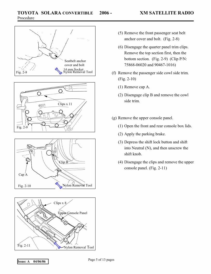
(f) Remove the passenger side cowl side trim. (Fig. 2-10)
(1) Remove cap A.
(2) Disengage clip B and remove the cowl side trim.
(g) Remove the upper console panel.
(1) Open the front and rear console box lids.
(2) Apply the parking brake.
(3) Depress the shift lock button and shift into Neutral (N), and then unscrew the shift knob.
(4) Disengage the clips and remove the upper console panel. (Fig. 2-11)
Seatbelt anchor cover and bolt
Fig. 2-8 Nylon Removal Tool14 mm Socket
Fig. 2-9
Clips x 11
Fig. 2-10
Clip B
Cap A
Nylon Removal Tool
Fig. 2-11
Clips x 8
Upper Console Panel
Nylon Removal Tool

TOYOTA SOLARA CONVERTIBLE 2006 - XM SATELLITE RADIO Procedure
Page 6 of 13 pages Issue: A 04/06/06
(h) Remove the front console box.
(1) Disengage the clips, and then remove the front console box. (Fig. 2-12)
(2) Disconnect the connectors.
(i) Remove the instrument cluster upper finish panel.
(1) Apply masking tape to protect the surface trim.
(j) Insert the nylon removal tool at the side edge of the upper panel to disengage the clips, and then slide the upper panel toward the rear of the vehicle to remove it. (Fig. 2-13)
(1) Place a protective cloth on the dash and place the upper panel on top of the dash.
NOTE: Connectors do not need to be disconnected. Do not put tension on the connectors.
(k) Remove the instrument cluster finish panel lower and head unit.
(1) Remove the bolts, and then pull the instrument cluster lower finish panel toward you to remove the head unit. (Fig. 2-14)
NOTE: Connectors do not need to be disconnected. Do not put tension on the connectors.
(l) Remove the glove compartment door.
(1) Disconnect the damper from the right end of the glove compartment box. (Fig. 2-15)
Fig. 2-12
Clips x 4
Front console box
Nylon Removal Tool
Fig. 2-13
Guide pins x 3
Clips x 5
Masking tape
Insert tool here
Nylon Removal ToolMasking Tape
Fig. 2-14
Clips x 4
Bolts x 4 Nylon Removal Tool
Socket 10 mm
Fig. 2-15
Screw Damper
Phillips screwdriver

TOYOTA SOLARA CONVERTIBLE 2006 - XM SATELLITE RADIO Procedure
Page 7 of 13 pages Issue: A 04/06/06
(2) Squeeze both ends of the glove compartment door, and then fully extend the box past the stoppers. (Fig. 2-16)
(3) Disengage the claws, and then remove the glove compartment door. (Fig. 2-16)
(m) Remove the lower glove box trim.
(1) Disengage the three (3) clips and claw to remove the lower glove box. (Fig. 2-17)
(n) Remove the upper glove box trim. (Fig. 2-18)
(1) Remove the four (4) screws and bolt as shown. (Fig. 2-18)
(o) Remove the A pillar trim on the passenger side. (Fig. 2-19)
Fig. 2-17 Glove box lower trim
Clips x 3
Claw
Nylon Removal Tool
Fig. 2-18 Screws x 4
Glove box upper trim
10 mm Socket Nylon Removal Tool
Bolt
Fig. 2-16 Claws x 3
Stoppers x 2
Nylon Removal Tool
Claw
Fig. 2-19
Clips x 2
A pillar

TOYOTA SOLARA CONVERTIBLE 2006 - XM SATELLITE RADIO Procedure
Page 8 of 13 pages Issue: A 04/06/06
3. Install the antenna.
(a) Clean the ground plate mounting area.
(b) Peel off the backside protective sheet of ground plate and affix the ground plate onto the dashboard as shown. (Fig. 3-1)
NOTE: Align the back edge of the ground plate with the dashboard line and right side of defroster vent as shown and install it carefully. Once attached, the antenna cannot be easily removed.
(c) Remove the backing from the antenna, and then fasten the antenna onto the middle of the ground plate with the antenna wire pointing forward. (Fig. 3-2)
(d) Tuck the three foam-covered sections of the antenna wire into the space between the instrument panel and windshield. (Fig. 3-2, 3-3)
(e) Insert the antenna wire into the corrugated tube right after the Nylon tape. Secure the corrugated tube with the cushion tape B. (Fig. 3-3, 3-4)
(f) Route the antenna wire downward toward the cowl side trim board area along the existing harness then rearward along the front and rear passenger doorsills.
Fig. 3-3
Nylon tape
Antenna wire
Nylon Removal Tool
FrontDashboard Passenger side
Fig. 3-1
Ground Plate
Front support bar
Corrugated tube (Antenna wire inside)
Cushion tape B
Fig. 3-4
Antenna
FrontFig. 3-2

TOYOTA SOLARA CONVERTIBLE 2006 - XM SATELLITE RADIO Procedure
Page 9 of 13 pages Issue: A 04/06/06
4. Route the Tuner Wire.
(a) Install and route the tuner wire from the center cluster and along the front support bar. (Fig. 4-1)
(b) Provide sufficient wire slack to connect to the tuner, and then secure the wire to the existing wire harness with five (5) lock ties A. (Fig. 4-1, Fig 4-2)
(c) Route the tuner wire and the antenna wire along the doorsill using the existing clamps. Use the cushion tape A to secure the wire to the body as shown. (Fig. 4-2)
(d) Route the tuner wire and the antenna wire along the existing cable and secure the tuner wire and the antenna wire to the existing cable with lock ties. Route the tuner wire and the antenna wire, then use the cushion tape A to secure the tuner wire and the antenna wire to the body as shown. (Fig. 4-3)
5. Install the Tuner.
(a) Install the L-brackets and ground cable onto the tuner. (Fig. 5-1)
Fig. 4-2
Lock tie x 4
Cushion tape A
Existing clamps
Antenna wire
Fig. 4-1
Foam
Lock tie A
Fig. 4-3
Lock Tie x 4
Tuner wireAntenna wire
Cushion tape A x 5
Fig. 5-1
GND wire
Phillips Screwdriver

TOYOTA SOLARA CONVERTIBLE 2006 - XM SATELLITE RADIO Procedure
Page 10 of 13 pages Issue: A 04/06/06
(b) Clean the bottom of the base brackets and apply butyl tape on them as shown. (Fig. 5-2)
(c) Clean the base bracket mounting area. Using the template, install base brackets with butyl tape to the rear floor pan of the vehicle. (Fig. 5-2)
(d) Remove, and then discard the template.
(e) Install the tuner and L-bracket assembly onto the base brackets using the M6 nuts. (Fig. 5-3)
(f) Secure the GND cable to the existing GND point on the vehicle, then bundle and secure the remaining wire length with cushion tape as shown. (Fig. 5-4)
(g) Plug in the tuner cable, then bundle and secure the remaining wire length with cushion tape A as shown. (Fig. 5-4)
(h) Plug the antenna cable into the tuner. (Fig. 5-4)
Fig. 5-4
Antenna cable Tuner cable
Cushion tape A
GND wire
Cushion tape A x 2
Fig. 5-2
Base bracket x 2
Template
Fig. 5-3 Mount nut x 4 10mm Socket

TOYOTA SOLARA CONVERTIBLE 2006 - XM SATELLITE RADIO Procedure
Page 11 of 13 pages Issue: A 04/06/06
6. Reinstall the Radio/Player Head Unit.
(a) Connect the satellite tuner cable and the connectors removed in Step 2. (i) (2) into the rear of the head unit.
(b) Insert head unit into opening and re-install the four (4) screws.
7. In Process Functional Test.
(a) Temporarily reconnect battery negative cable.
(b) Turn ignition key to ACC position.
(c) Press the power button on the receiver/player head unit. Verify the backlighting illuminates.
(d) Press and release the "SAT" button on the head unit.
(1) Verify that a satellite channel is received, or a "NO SIGNAL" message appears on the display.
NOTE: If "ANTENNA" appears (flashing) on the display - then the antenna cable is disconnected from the satellite tuner.
NOTE: If the head unit will not tune or go into satellite mode - then the tuner cable is disconnected from the satellite tuner.
(e) Disconnect battery negative cable.
8. Complete the Reassembly of the Vehicle.
(a) Reconnect any disconnected connectors.
(b) Verify the panels fit together properly with no uneven gaps between them.
(c) Rear seat back installation: Specified tightening torque: 18 N·m (185 kgf·cm) (13 lbf•ft)

TOYOTA SOLARA CONVERTIBLE 2006 - XM SATELLITE RADIO Procedure
Page 12 of 13 pages Issue: A 04/06/06
(d) Front passenger seat belt installation: Specified tightening torque: 42 N-m (430 kgf·cm) (31 lbf-ft)
(e) Reconnect the vehicle’s negative battery cable. (Fig. 8-1)
(1) Position the battery negative cable at the original factory position.
(2) Tighten the nut to 4.1 N-m (36 lbf-in).
(3) Do not touch the positive terminal with any tool when replacing the cable.
(f) Clean up and remove any trash.
(g) Place the owner "XM Satellite Radio" brochure and the "Owners Manual" in the glove box.
(h) Start engine to ON. Close the convertible top and reposition the driver’s seat. Switch to OFF
Fig. 8-1
Socket (10 mm), Torque Wrench
Negative Battery Cable

TOYOTA SOLARA (CONVERTIBLE) 2006 - XM SATELLITE RADIO Checklist - these points MUST be checked to ensure a quality installation.
Check: Look For:
Page 13 of 13 pages Issue: A 04/06/06
Accessory Function Checks
Satellite Radio Tuner.
Receiver/player Assembly.
Vehicle Function Checks
Courtesy light
Hazard switch.
Rear passenger seat back
Proper operation of the removed seat lock
mechanism.
HVAC.
Multi-information displays.(Clock,
Temp., and MPG meter)
Operation of the L&R seat heater switch.
Operation of the 12V outlet switch.
*Verify the proper operation of the
Satellite Radio Tuner.
*Verify the proper operation of the
Receiver/player Assembly
*(Refer to the receiver assembly and
radio owner’s manuals.)
Proper function of the courtesy light
Proper operation of the hazard switch.
Verify the rear passenger seat back is in
the upright position and the latch secured
Proper operation of the removed seat lock
mechanism.
Proper operation of the air conditioning
system.
Verify the proper operation of the multi-
information displays.
Verify the proper operation of the L&R
seat heater switch.
Verify the proper operation of the 12V
outlet switch.