Embed Size (px)
Citation preview

Federal SystemsDivisionTRW Space &Technology Group
(IAS1-CJB-174904) SATELLITE VCICE BROADCASTSYSTEM STUDY. VCIUHE I: EXECUTIVE SUMMARYContractor Report, 11 Apr. 1S£4 - 11 Jul.1985 (TRW, Inc., Eedondo Eeach, Calif.)
RrV
N86-24678
Unclasp HC A03/af CSCL 17B G3/32 43076
Satellite Voice BroadcastSystem Study
Volume 1 - Executive Summary
July 1985
Prepared forNASA Lewis Research Center
https://ntrs.nasa.gov/search.jsp?R=19860015407 2018-06-02T18:55:49+00:00Z

1. Report No.
CR 1749042. Government Accession No 3 Recipient's Catalog No
4 Title and Subtitle
SATELLITE VOICE BROADCAST SYSTEM STUDYVOLUME 1 - EXECUTIVE SUMMARY
S. Report Date
July 1985
6. Performing Organization Code
7 Author(s)
Dr. Michael Horstein
8. Performing Organization Report No
10 Work Unit No.
9 Performing Organization Name and Address
TRW Inc.One Space ParkRedondo Beach, CA 90278
11. Contract or Grant No
NAS3-24232
12. Sponsoring Agency Name and Address
National Aeronautics and Space AdministrationWashington D.C., 20546
13. Type of Report and Period Covered
Contractor Report4-11-84 through 7-11-85
14. Sponsoring Agency Code
15. Supplementary Notes
Contract Monitor Charles E. Provencher, Jr.NASA Lewis Research CenterCleveland, Ohio
16. Abstract . -This study investigates.the feasibility of providing Voice of America (VOA) broad-casts by satellite relay, rather than via terrestrial relay stations. Satellitevoice broadcast systems are described for three different frequency bands: HF(26 MHz), VHF (68 MHz), and L-band (1.5 GHz). The geographical areas of interest•at HF and L-band include all major land masses worldwide with the exception of theth-S-., Canada, and Australia. Geostationary satellite configurations are consideredfor both frequency bands. In addition, a system of subsynchronous, circularsatellites with an orbit period of 8 hours is developed for the HF band. VHFbroadcasts,-wWch-a-re~oonfiwd"to~ the So'vtetrtlnionv are provided by a system ofMolniya satellites.
•Satellites intended for HF or, VHF broadcasting are extremely large and heavy. Sat-ellite designs presented here are limited in size and weight to the capability ofthe STS/Centaur launch vehicle combination. Even so, at HF it would take 47 geo-stationary satellites or 20 satellites in '8-hour orbits to fully satisfy the voice-channel requirements of the broadcast schedule provided by VOA. On the other hand,three Molniya satellites suffice for the geographically restricted schedule at VHF.
-i
At L-band, only four geostationary satellites are needed to meet the requirementsof the complete broadcast schedule. .Moreover, these satellites are comparable insize and weight to current satellites designed for direct broadcast of videoprogram material.
17 Key Words (Suggested by Authors))
Voice of AmericaSatellite voice broadcastingLarge space structuresPhased-array antennasHiqh-oower transmitters
19. Security Classif (of this report)
Unclassified
18 Distribution Statement
Unclassified - unlimited
20 Security Classif. (of this page) 21. No. of pages 22. Price*
Unclassified 42
*For sale by the National Technical Information Service, Springfield. Virginia 22161

Federal SystemsDivisionTRW Space &Technology Group
Satellite Voice BroadcastSystem Study
Volume 1 - Executive Summary
July 1985
Prepared forNASA Lewis Research Center
Federal SystemsDivisionTRW Space &Technology Group
Satellite Voice BroadcastSystem Study
Volume 1 - Executive Summary
July 1985
Contract No. NAS3-24232
TRW SpaceTechnology GroupOne Space ParkRedondo Beach, CA 90278
Prepared for:NASALewis Research Center21000 Brookpark RoadCleveland, Ohio 44135
Approved:
M/HorsteinProject Manager
:. SharpiesManager, Systems Engineering

1. INTRODUCTION
The Voice of America (VGA), a division of the U.S. Information Agency
(USIA), provides voice broadcasts to most areas of the world. These
include, on a daily basis, more than 30 hours of English broadcasts andmore than 100 hours of foreign language broadcasts. The dominant broadcasttype is news, followed by features, news related material, music, and
editorials. News sources include the wire services, domestic and foreign
news bureaus, foreign broadcasts, and periodicals.
VGA's technical headquarters are in Washington, DC. VOA programming,
which originates in Washington, is transmitted to listeners via relay
stations located in the U.S. and in a number of foreign countries, as wellas through leased facilities. Most transmissions to U.S. and foreign relaystations are at high frequency (HF), although in some cases satellite linksare now used.
Many of the relay station transmission facilities are quite old and/orof lower power than desired. Consequently, VOA has embarked on a $1 billionmodernization program to replace antennas at high priority sites, upgrade
transmitters at existing relay stations, and begin construction of severalnew projects.
In conjunction with the modernization effort, VOA is considering thepotential application of new technologies. To this end, the USIA has
funded NASA to contract with two satellite manufacturers to investigate therole that satellite direct broadcasting might play in VGA's future opera-tions. This volume summarizes findings of a 1-year study conducted by TRWin answer to this question.
To be of value, broadcasting must take place at frequencies within the
bandwidth of receivers in the hands of the populace. The most widelyreceived shortwave bands are between 6 and 11 megahertz. A considerablysmaller percentage of radios can receive frequencies between 20 and 26
megahertz. However, to be reasonably assured that satellite transmissionswill penetrate the ionosphere, they should be above 20 megahertz. An
additional reason for desiring a higher broadcast frequency is to reduce
R5-059-85

the size of the satellite antenna, as the antenna diameter needed to pro-duce a given beamwidth varies inversely with frequency.
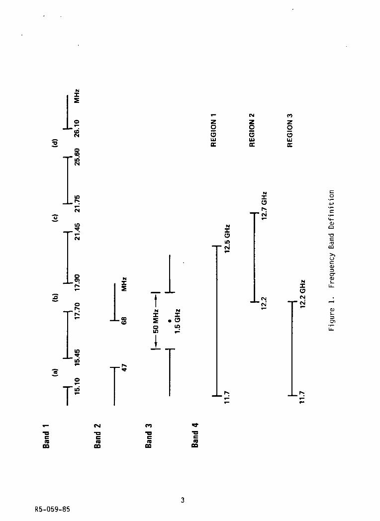
The array of frequency bands considered in this study is indicated inFigure 1. Band 1 comprises four RF subbands for which direct broadcasting
allocations exist. Because of the questionable nature of ionospheric pene-tration at the lower subbands, Band 1 system designs are described for the
top subband.
Band 2, which lies in the VHF band, was considered in this study only
for broadcasts to the Soviet Union, in which there exists a significant
population of suitably tunable receivers. Because of the inverse rela-
tionship between antenna size and frequency, Band 2 systems are assumed tooperate at 68 megahertz.
Band 3 receivers are virtually nonexistent today. However, because of
the long-range objectives of this study and the attractiveness of thehigher frequency bands for direct broadcasting, the characteristics of Band
3 broadcast systems were investigated as well.
The three frequency bands under the Band 4 heading are currently .
allocated to direct broadcasting in Regions 1, 2, and 3 as defined by theInternational Telecommunications Union. Following the initial phase of
this study, TRW was directed by NASA to pursue system concepts only for
Bands 1, 2, and 3.
Band 1 transmissions employ double-sideband amplitude modulation
(DSB-AM), with a maximum baseband frequency of 5 kilohertz. Broadcasts inBands 2 and 3 use frequency modulation (FM), with a maximum baseband fre-
quency of 15 kilohertz and a maximum deviation of 75 kilohertz. The RF
bandwidths of the DSB-AM and FM transmissions are 10 and 250 kilohertz,
respectively.
The present study is confined to developing satellite voice broadcast
system concepts for the different frequency bands. A subsequent contractwill be awarded by VOA to develop projections of receiver populationsworldwide. The results of the latter study will be evaluated by VOA inconjunction with the system concepts developed under the present pair of
contracts to assess the attractiveness of those system concepts.
R5-059-85
z5
8
guiDC
CM
O5UJtr
CO
g5UJoc
X),r*
CM
.*.CM
ZOinCM'
co
14-a>o
(OCQ
or*
'i^
NZ
.00to
CNJ
'CM'
ZCJCMCM'
NZ
oIT)
Zoin
oa)3
ai
a>
in•*in
T!
COO3
reCQ
re00
reCO
R5-059-85

Once this assessment has been made, it will be possible to evaluate
the merits of satellite broadcast systems as a complement to, or substitutefor, terrestrial broadcast facilities. This comparison will be facilitated
by life-cycle costs developed for each of the satellite systems as part of
the present study.
The feasibility of satellite voice broadcasting depends on the
required electric field strength. The baseline system requirement is 300yV/m in Band 1 and 250 uV/m in Band 2. In Band 3, the signal strengthrequirement is stated differently — namely, to produce a demodulated
signal-to-noise ratio of 49 dB with an indoor receiver and an outdoor
antenna. The field strength requirements in Bands 1 and 2 weresubsequently relaxed in considering a number of system variations.
Following a series of tradeoffs and analyses performed in the initialstudy phase, four system concepts were selected for further investigation.
They are enumerated by frequency band and orbit below. The inclination of
the 8-hour orbit is 28.5 degrees (equal to the latitude of Cape Canaveral),
to maximize the satellite weight in orbit.
System Band Orbit
1 1 Geostationary
2 1 8-hour circular
3 2 Molniya
4 3 Geostationary
Each of the four satellite systems is designed to satisfy the channel
requirements of a broadcast schedule provided by VOA. This schedule spec-ifies the number of voice channels to be provided to each of 15 geographi-cal zones at 15-minute intervals throughout the day. The broadcast zonesare defined in Figure 2. (System 3 deals only with the four zones thatconstitute the Soviet Union.) A compressed version of the broadcast
schedule, in which the channel requirements are allowed to change only at1/2-hour intervals, is shown in Figure 3.
R5-059-85

co
O)O
OJ
O
01to
oCO
O)
R5-059-85

<N
<D
to
O3
Orsj
60
03
CO
CJ
O3O'o
*o
Q3
"|
03
"coO
COO3
ID
1-r-
»-
T—
1-
CM
CM
CM
f
r-t-
CM
CM
CM
CM
CM
CM
CM
CM
CM
r-
*-
CMCM
r-CM
CM
CM
CM
CM
t-
V
t-
«-
t-
«-
CM
CM
CM
CM
CM
CM
CM
CM
CM
r-
V-
»-
i-
CM
CM
CM
CM
«-
»-
»-
«-
t-
r-
r-
»-
r-
CM
CM
CM
CM
CM
CM
i-
i-
w-
«-
CM
CM
*-
i-
f-
i-
T—CM
i-
T-
^
1-
,-
t-
r-
CM
CM
f
(005
PO
(OCM
T—
t-
t-
«-
t-
r"
t—»-
CM
(0O)
r-
00CM
t-
r-
»-
•-CM
CMCM
CM
CM
CM
CM
CM
CM
CM
CM
«-
T-
«-
CM
CM
CM
CM
«-
r-
f
i-
CM
CO
CO
COCO
COCO
CM
CM
CM
CO
t-
CM
i-
CM
T—r-
CM
CO
CO
CO
CO
i-
CM
t-
t-
»—.-
t-
»-
•-t-
t-
t-
«-
^CM
r-r-
r-
f-
r-
r-r-
r-
«-
CM
CM
f
t-
«-
T-
r-
f
»-
i-
tr>CM
*-*"r-
^
t-
(O
CM
i-
t-
«
»-
»-
<-
r-
^CM
*-
.-
»-
r-
r-
»-i-
i-
CM
CM
CM
r-
«-
f-
•-t-
t-
<-
COCOCOCO
CM
CO
*•CM
*•
CM
CM
CO
CM
,-
r-
^m
i-
t-
»-
i-
i-
CM
»-
»-
TJ-
in
CM
r-
r-
CM
CM
CO
CO
CO
CO
CM
CO
*•
(O
CM
CM
CM
CM
CM
CM
CM
T-
1-
t-
r-
«-
T"
<-
CM
»-
»-
i-
r-»-
i-
r-
»-
«-
r-
r-
r-
f-
»-
»-
i-
»-
8wCM
(M
S
in
CJ
o>
00ccDOzI
LU
V}crLJU
zD
O)
3-oO)
1/1
<T3O
X3(O
co
O)
3cn
(8
in
M
CM n to
UJ
1
R5-059-85
2. SATELLITE SYSTEM DESIGN
Because of the large satellite power requirements in Bands 1 and 2,
the antenna beamwidth is a critical design parameter. It is found that a
3-degree beamwidth, as viewed from geostationary orbit, represents a goodcompromise between the joint desires to: 1) avoid radiating power outside
zone boundaries, and 2) minimize antenna size. For orbits other thangeostationary, the beamwidth is modified to illuminate the same size area
as from geostationary orbit. The power requirements in any frequency bandare thereby rendered invariant to the choice of orbit.
The satellite RF power requirements depend on the number of channelstransmitted to each beam area. It is assumed that the same number of
channels are transmitted to each area of a particular zone (but not neces-sarily by a single satellite). Because it is not necessary that every
channel be transmitted throughout an entire zone, the number of channels
per beam area will sometimes be less than the corresponding entry in Figure
3. The transmitter power assigned to Zone i can be written as C-jN-jP^g,where Ci is the number of channels required in each beam area of Zone i, NI-is the number of beams needed to cover Zone i, and P^g is the transmitterpower assigned to each channel in a given beam (i.e., the transmitter power
per channel-beam). Thus, the transmission requirements of a zone arecharacterized by its C x N product (i.e., the number of channel-beams
associated with that zone).
The channel-beam demand of the broadcast schedule, as it applies toSystems 1,2, and 4, is shown in Figure 4. Broadcast service is measured
in units of channel-beam-hours (CBH). The total daily service called forby the schedule in Figure 4 is 894 CBH.
The channel-beam demand for System 3 is given in Figure 5. Differencesbetween corresponding entries in Figures 4 and 5 result from different num-
bers of beams being required for zonal coverage from geostationary orbitand Molniya apogee.
The number of satellites required to meet the demands of the broadcast
schedule depends on the channel-beam capacity of an individual satellite.Satellite capacity, in turn, depends on the lift capability to low earth
R5-059-85

O »- CM CO ir>CM
CM
CMCM
CM
O)
<0
c/)
CO
"O
CO
CO
"coeoOcu
CDO*-•
CO
.ex
CO
° CO•o -cu•a £co
03 £
ao
eo «-3o O)
ECO03
CO
"a3
CO
CJ
«*05CO
co
(O
in
co
CM
(M
CM
CM
(M
CM
V
*•
«
CM
(M
CM
*
V
V**
*
•fM
CM
V
t
CM
CM
V
V
V
tf
<»
CM
CM
CM
CM
CM
CM
V
«
«»•
V
V
*
^
V
^
t—r+rxr-«
-
^r»«•<r-vt"»vr-*^r*
r*r«
r*.h.
r*.r»r**t
i»vv«•V-V
nnwn<o(0
n
n
coa
n<£>
CO
cvCM
CM
CM
CM
CM
CM
CM
CM
*r(0
or-CM»0
(0
CM
CM
CM
CM
CM
CM
CM
CM
CM
CM
(0
0
CM
00
CM
CM
«
CO
CO
co<B
(O
to<fi(O
(0
10
10<o(O
toCO
CO
CO
(0ID
to(O
CO
CO
r»rsfv»v»•vn»nr-VT"Vf"«
^V
r«*r»
*f>.rv«•?"vT»**vr«.
^r»
CM
CM
CM
CM
CM
CM
CM
CM
CM
CM
CM
*CM
CM
(M
CM
CM
CM
CM
CM
CM
V
«»
CM
CM
CM
CM
CM
«••
^T-
inCM
f—•-•-^
^(0
CM
v~
^
nCO
CO
CO
coCO
(0
CO
CO
CO
CO
CO
coco
CO
(O
V
to
coco
*•
<«vvCM
CM
CM*•CMT-
00
CM
i—to9-00
(Ofto00
eoCM
00
CM
CM
CM
CM
CM
CM
CM
CM
«»
CM
CM
fNCM
CM*•
rvr»
v~4
CM
CM
CM
CM
CM
CM
CM
CMV
^nT-
n
^
^•«•
CM
CM
CM
CM
CM
CM
CM
*•
CM
CM
CM
CM
CM
CM
CM
CM
CM
CM
CM
CM
CM
<M
CM
CM
CM
CM
COCM
CMCM
CM
\t>
co
coocDoz
a>3-aa>o
CO
rao•ooca•oa>
oc01>zD
roO)
CO
O)
C(O
^ta)
in
UJ
ON
R5-059-85

COS
CO
_JUJzZ
o0oc .
CNI UJ03
" 1_C: Z*-<
^'g
CD03
CD
"55CDtn
CM
<o
«
CM
CM
rt
«
00
00
00
*
CO
en
CM
CM
CM
CM
CM
*CM
CM
CM
O
CM
CM
CM
CM
CM
*
(M
CM
CM
CM
CO
CO
CO
CO
O
CM
•
o
•> ,« *°•CO 5Boc 5
0 gr. z ',
1 J1 UJill z
1 Z* H z
•J u^ u.
« S o"* UJ OC
> UJ
z i«. D D
Z
CM
CM
CM
CO
*CM
CM
CM
CM
*
*
*
*
*00
•»*•**
en
en
en
en
en
*
*
*
*CM
CM
1-
en
*
*•*
*CM
CM
CM
CM
CM
O
00
CD
coo
«o
«*•^^
en
OO
tv +J<N -r-
O
r* rO
S CO s:OC
S oO °O» T3™ 1 Cuj is 1« H °^5 «^ QJ
CO CD
^ !£ "oj^ c
«D = 5
CM
T3
•- 03
LOr^ OJ
23CD
CO Ll_^»
Ul
I
UJ
ON
R5-059-85

orbit (LEO) of the Space Transportation System (STS). The latter is takento be 65,000 pounds; this capability should be available by the end of the
decade.
The resulting satellite capacity values are shown in Figure 6.
Differences in satellite capacity between Systems 1 and 2 result from thedisparity in STS/Centaur payload capability. On the other hand, the pay-
load difference between 8-hour and Molniya orbits is minor. The difference
in satellite capacity between Systems 2 and 3 results, instead, from the
difference in RF power requirements.
2.1 Baseline System Designs
For the geostationary satellite systems, three satellite locations are
needed to provide broadcasting to all 15 zones: 65° west, 30° east, and
115° east longitude Each zone is assigned to one of the three locations.
The associated channel-beam requirements at each location are then summed
for each 1/2-hour of the day. The maximum sum for any 1/2-hour period at
each location determines the satellite requirements at that location.
In the case of the Band 1 geostationary system, the number of satel-lites needed at each location is found by dividing the maximum channel-beamdemand by two, which is the satellite capacity. The resulting numbers ofsatellites are: 11 at 65° west, 22 at 30° east, and 14 at 115° east. Thetotal number of satellites is therefore 47.
By contrast with the Band 1 and 2 requirements, the required RF power
per channel-beam in Band 3 is only 70 watts. Moreover, a 16-ft antenna
suffices to produce a 3-degree beam from geostationary orbit. As a result,
a single satellite could provide all required broadcasting from each of the
orbit locations. However, the maximum channel-beam demand is considerably
greater at 30° east than at either of the other two locations. It is more
efficient, therefore, to design a satellite to handle the maximum require-
ment at either 65° west or 115° east (which is 27 channel-beams) and todeploy two such satellites at 30° east. Thus, four satellites are requiredin all. Each satellite weighs about 4000 pounds.
As can be seen from Figures 5 and 6, the satellite capacity in Molniyaorbit (12 channel-beams) exceeds the maximum broadcast requirement -in any
1/2-hour period (10 channel-beams). Moreover, a single satellite can be
10R5-059-85

09
5 re reCO O9 CO
5 m >-09
CO CSI
ECO09
-Q
"3
O9
09
03 CO
•E COk. 09
CO 09 QQ
CO
CD•
CDCDCD
LT)LO
re -53r re >« -2 =
co£fCO £
CO«3-COCO
COr--.
kk
CDCM
cn05
CO
aLUCD
oI
CO
CO
oo*—•en
OooCO
03
cuu.CO
».
CO
COCQ
« 'S•^^ _a2 ocu
cao
- oco cu03 05
uQ.ro
(U(O00
OJ
re
Qi O• "
«
r- ^ CNJ CO
09
.— QJ^5 *-
re -CO
CO
09 coE§>- euoo -a• •
cu*—*o
11R5-059-85

placed in Molniya orbit so as to maintain continuous visibility of the four
Soviet zones for nine hours. It follows that three such satellites, each
broadcasting for eight hours per day, can fully satisfy the Band 2 broad-
cast requirements. The eight-hour broadcast interval for each satellite iscentered about apogee passage. Because of the slow angular motion of thesatellite near apogee, transmission requirements during the broadcast per-iod may be assumed constant and equal to those obtaining at apogee.
System design for subsynchronous orbits is considerably more difficult
than for either geostationary or Molniya orbit. The reason is that satel-
lite coverage of the various zones is time varying. Orbit periods of 6, 8,
and 12 hours were considered. The 8-hour orbit was selected, primarilybecause it provides a better balance between satellite coverage and
capacity.
Because the broadcast schedule is divided into 1/2-hour intervals, the
following rules are observed:
a) Broadcasts must begin on the hour or 1/2-hour
b) The minimum continuous broadcast period is 1 hour
c) Broadcast periods are constrained to be multiples of 1/2 hour
Additionally, it is assumed that satellite/zone assignments are not varied
during any 1/2-hour period. .
With these ground rules, it is found that 20 satellites in 8-hour
orbit are required to provide at least single-satellite coverage of the 15
zones during broadcast periods. However, this minimum-coverage constella-
tion does not include sufficient satellite capacity to satisfy the channel-
beam requirements throughout the day. Of the daily total of 894 CBH speci-
fied in Figure 4, only 735 CBH can be provided.
Feeder links for satellite broadcasts should operate in real time, ifat all possible. The alternative (which does not apply to stationary
satellites) is to record the program material when the satellite is in viewof a feeder-link station, for subsequent broadcast when the satellite is in
view of the target area. In order of preference, feeder-link stationlocations include:
12R5-059-85

1) U.S. (CONUS plus Alaska and Hawaii)
2) U.S. territories
3) Friendly host countries.
If none of these possibilities exists, real-time transmission can still be
accomplished by satellite relay.
For the two geostationary satellite systems, each of the three orbit
locations is visible from at least one of the desired station locations.
Therefore, real-time feeder links can be established in all cases. For theMolniya system, each satellite is visible from CONUS throughout its 8-hour
broadcast period. Consequently, real-time feeder links are possible in
this case as well.
Two different ground tracks are involved in the 20-satellite, 8-hoursystem. For one ground track, real-time feeder links can be established
for all but 1 hour of the day. For the other ground track, there is a
2 1/2-hour period during which the satellite is not in view of any of thedesired station locations. For these intervals, either satellite relay orstorage of program material is necessary.
2.2 System Variations
A number of system variations were examined, based on reductions in
coverage, number of broadcast channels, or required field strength. Of
these, two sets of variations are of particular interest.
The first variation involves transmission of a single voice channel to
each of the 15 zones during prime listening hours. The latter are definedto comprise two hours in early morning and two hours in early evening. A
broadcast schedule that accomplishes this objective is shown in Figure 7.
The entries, which represent the channel-beam requirements in each 1/2-hour
period, are equal to the number of beams needed for zonal coverage. Theschedule in Figure 7 minimizes the maximum number of channel-beams required
of any satellite.
For a geostationary system designed to operate in Band 1, foursatellites are needed at each of the previously selected orbit locations to
satisfy the broadcast requirements of Figure 7. In all, 12 satellites are
13R5-059-85

CD
03
OCD
"CDo
CDDC
co
CDCD
CO
O
CD_a
=3
CD+-*CDo
COCU
CO
03-a
CD
03aV)
ECD03
op"33
CD
COCD
CD^-^O
CM
COCM
CMCM
CM
O)
00
CD
If)
CO
CM
oo
CO
CM
CM
CM
CM
CM
CM
CM
CM
CM
CM
CM
CM
CM
CM
CM
CM
IX
IX
IX
IX
^
^
^IX
CO
CO
CO
CO
COCOCOCO
CM
CM
CM
CM
CM
CM
CM
CM
CO
CO
CO
CO
CO
CO
CO
CO
px
|X
^
^
%
^
^IX
CMCM
CM
CM
CM
CM
CM
CM
,-
«-
i-
r-
«-
I-
»—t-
CO
COCO
CO
CO
COCO
CO
^^1
Tt
5tn-
*^1
CMCM
CM
CM
CM
CM
CM
CM
IX
rxrx
^
»
rxIX
IX
CM
CM
CM
CM
CM
CM
CM
CM
CM
CM
CMCM
CM
CM
CM
CM
CMCM
CM
O)
co
CM
COccDOzI
UJ
CCLU
O)
00
«0
<Dco
O)Q.
O)
c
*oO)
oC7)
aCL.
<D
O)
UC/O
OT3
O
CQ
dJ
OJ
S-D-
O)
co
CM
in
UJZON
R5-059-8514
required. For a Band 3 system, a single satellite with a capacity of sevenchannel-beams is needed at each orbit location.
For an 8-hour-orbit system, the orbit inclination is increased to 37
degrees. This reduces the satellite capacity from six to five channel-
beams, but it also reduces the number of satellites needed for complete24-hour zonal coverage from 20 to 16. Some gaps in northern coverage
result from use of a smaller number of satellites. However, a 12-satellite
constellation can provide 180 CBH of broadcasting daily, compared with 192CBH provided by a 16-satellite constellation and 196 CBH called for by the
schedule in Figure 7. Therefore, a 12-satellite constellation is thepreferred choice.
In the second set of variations, the field strength requirement isreduced to 150 wV/m in both Band 1 and Band 2. This represents a 6 dBpower reduction in Band 1 and a 4.4 dB power reduction in Band 2. These
power reductions permit a decrease in number of satellites and/or satellite
complexity.
For the geostationary Band 1 system, the fourfold reduction in field
strength can be translated into a similar increase in satellite capacity,to eight channel-beams. As a result, 11 satellites suffice to (nearly)
satisfy the requirements of the broadcast schedule in Figure 4.
The baseline Molniya satellite capacity of 12 channel-beams (at afield strength of 250 vV/m) completely satisfied the demands of the broad-cast schedule for the four Soviet zones. Nothing would be accomplished,
therefore, if the reduced field strength were used to increase the satel-lite capacity. Instead, the satellite size and weight are reduced, with an
individual satellite still capable of providing the full broadcast service.
If the antenna diameter is halved, for example, the satellite beams
are expanded to 5.4 degrees. Each of the four Soviet zones can be coveredby a single beam of this size. With a minor adjustment to the broadcast
schedule, the maximum broadcast requirement in any 1/2-hour period
(expressed in terms of a 5.4-degree beamwidth) is three channel-beams.
On the other hand, the satellite capacity based on the full STS liftcapability is nine channel-beams. It is possible, therefore, to downsizethe satellite by using less than the full STS lift capability. A satellite
15R5-059-85
capable of supporting three channel-beams requires only 40,000 pounds oflift capability, as compared with the full STS capability of 65,000 pounds.Three such satellites, spaced by eight hours along a common ground track,fully satisfy the demands of the broadcast schedule.
For a subsynchronous satellite system, the most straightforward way to
take advantage of the field-strength reduction is to increase the orbit
inclination from the 28-degree value used in the 8-hour baseline system.
As mentioned earlier, 16 satellites can provide 24-hour coverage of all 15
zones at an inclination of 37 degrees, while a reduction in the number of
satellites to 12 introduces some gaps in zonal coverage. Nevertheless,
because of the 24-channel-beam satellite capacity at the reduced fieldstrength, 12 satellites can provide 864 CBH of broadcasting daily (out of
894 demanded).
A second option is to reduce the satellite antenna size through a
doubling of the equivalent geostationary beamwidth to 6 degrees. Because asingle beam will now radiate power well outside the boundaries of many zones,the effective capacity of the satellite is reduced by this approach. How-
ever, 12 satellites can still provide 845 CBH daily (expressed in terms of an
equivalent geostationary beamwidth of 3 degrees).
A final system alternative is to increase the orbit altitude to a
value corresponding to (for example) a 12-hour period, while maintaining a
3-degree beamwidth. The wider coverage from 12-hour orbit permits a signi-ficant reduction in the number of satellites needed for 24-hour coverage ofall zones. Because of the increased satellite capacity that accompanies afield strength reduction to 150 uV/m, an 8-satellite constellation can
provide as many as 851 CBH daily.
The salient features of the system designs for a 150 pV/m field
strength requirement are summarized in Figure 8.
One final system variation concerns the use of single-sideband ampli-
tude modulation (SSB-AM), rather than DSB-AM, in Band 1. An SSB-AM signalformat requires 7.8 dB less transmitter power than DSB-AM, based on a100-percent modulated double-sideband signal. This decrease in transmitterpower is equivalent to a field strength requirement of 122 pV/m. The
satellite requirements are therefore somewhat less than those for a field
16R5-059-85

0
fc•= ««
00
^ ^ COCO
cO)
o>
3CT
+= 52 E*> 2§ CD
CD
oCO
oCO
oCO
oCO
oCO
enO)
-o'oi
oLO
s-o
oB09
TOCO
r— r- t— *— CM
H3
CO
OJ
3O)
CD
CO
eoo03
CD
CD>-
•fr -r CMCO CO T—
R5-059-8517

strength of 150 yV/m. It is found that seven geostationary satellites can
provide a daily total of 882 CBH. For an 8-hour-orbit system, 12 satel-
lites are again needed for reasonably complete zonal coverage. Each of thesatellites can be made lighter than for the 150 uV/m field strengthrequirement, while providing the'same amount of broadcast service.
3. LIFE CYCLE COSTS
To develop life cycle costs (LCC) for the various systems, a nominal20-year program span was adopted, together with a satellite life of 7
years. Schedules depicting the satellite development period and the cumu-
lative launch profile for the four baseline systems are shown in Figure 9.
Two complete sets of satellites (i.e., twice the fleet quantity) arerequired in each case. In addition, a 10-percent spare-satellite contin-gent (not shown) has been assumed. If the broadcast service provided is
taken proportional to the number of satellites on orbit, each system pro-
vides the equivalent of 14 full years of service over the program span.
In addition to the satellite costs, the LCC include launch costs of$100 million for a full STS load and $58 million for a Centaur-class upper
stage. Additionally, there are earth stations for satellite control and
feeder-link transmission. There are two such stations in System 3, four in
Systems 1 and 4, and seven in System 2. The cost per station is taken as
$10 million. Finally, there are operations and maintenance costs of $12.5mi 11 ion/station/year. The LCC for each baseline system is given in Figure10.
To provide a measure of system effectiveness, the LCC are normalizedto the broadcast service provided. The latter is computed by multiplying
the number of CBH provided daily by 5110, which is the number of days in 14years. The entries in the last column of Figure 10 are the normalized LCC
for the four baseline systems.
The high normalized cost of the geostationary system is attributable
to the small satellite capacity of two channel-beams. By contrast, thecapacity of a satellite in 8-hour orbit is six channel-beams. The dailynumber of CBH per satellite is approximately the same for the Molniya and
8-hour systems. However, the 8-hour system benefits from considerably more
18R5-059-85

cu
cuCOCO
COcu
cucoCO
CO
0CM
O3
CO
r-
CO
LO
«3-
CO
CM
^CD
03
CO
P»-
CO
LT5
*i-
CO
CM
-COCU>-
^fCD
r .CO
CDr*.
r>.
coCO
IDin
r .«a-CD*rCMco
^-CNJ
CO«—
CO
X
X
X
X
X
03 >•
•BaLU 03 .c08 "5 yj
o iio co _J
= E«u £co coCO >-
CD CO
Orl-
COCO
CMCO
COCNI
1-CNJ
Ocsj
CO
CSJ
CO
•3-
X
X
X
X
a, >r.20
LU CD t-
o3 "5 «S iia C_D _j
CNJ
.1 E-= 03QJ 4>^co coCO =>-
CO CO
CO
^~
CO
-X
X
X
X
X
2 -.2 aLU CO r-o3 "5 "£ iia co _j
CO
I Eeu £co coCO >-
CO CO
CO
CO
«3-
CNJ
X
X
X
eu £T•£&
LU fS j=o3 "5 cj
£ iia cj _3
*3-
.1 EQ3 22co coCO >-
CO CO
Q5O
a>co
COCOO-a
COO
O
CO
CO<u
CO
cu
COOi
T3
CU*coCO
uCO
cu
3T3a>-Co
OO
c3to
-oc(O
cQJ
Q.O
'aiO)o
CD
GO
CDC
airo
CQ
CTi
aiS-3
19R5-059-85

*
ilCOcncd
oor*.CO
inIT)
ECOen O03 *—
CD
O3
=CD
_CC_D
£23O
LOco *3-r». inco CD
LTJ
OO
03
O3
CO *—
CD
CDCNJ
OUJCD
CO
CD>.'co
o
CDCO
09
00
T— t— CN
OUJCD
CO
T— CM CO
O3
CO
CDO3
O3
oO3
O3
£ *— OCD i_ •= 03 £-g S «^J O Qj
— 0 3 - 9
illn g «- -o «£ = 0 3 , .
2 S3 "00 > -^
O "53 CQCD Q CJ)* •«— *
CO4->COO
(_>
0)
13>,CJ
£_jE(U
4-»CO>,ooO)
o>toto
CO
s_3CD
20R5-059-85

"learning" and also has the nonrecurring satellite cost spread over alarger number of satellites. Hence, the smaller LCC/CBH for the 8-hoursystem.
. System 4 has by far the smallest LCC/CBH. The satellites in this system
are not very different in size from some current commercial satellites.Operations and maintenance costs, which are minor for the other three sys-
tems, are estimated to approach 50 percent of the System 4 LCC.
Measures of system cost other than the normalization of LCC with
respect to CBH may be of interest. For example, the system cost per year
of (full) operation is found by dividing the LCC by 14. In round numbers,
the annual costs of Systems 2 and 4, which provide comparable amounts ofprogramming (735 versus 894 CBH daily), are $1 billion and $140 million,
respectively.
Life cycle costs for the system variations are presented in Figure 11.The effectiveness of the Band 1 geostationary, prime-time system is com-parable to that of the 8-hour system because both require the same numberof satellites. The relative loss of effectiveness of the 8-hour system for
prime-time broadcasting is attributable to underutilization of satellitecapacity, particularly over the mid-latitude zones. The LCC/CBH of the
Band 3 geostationary, prime-time system is four times that of the baseline
system, because the service provided is five times smaller while the
life-cycle number of satellites is only reduced from nine to seven.
The number of satellites in the 8-hour system designed for a field
strength of 150 p.V/m is determined by coverage requirements, as is the casefor the 8-hour prime-time system. The LCC/CBH is much smaller for the
former system because of the greater broadcast service provided. The smallLCC/CBH for the geostationary system has the same explanation. The LCC/CBHfor the 12-hour system is only slightly lower than for the 8-hour system,despite the decrease in number of satellites, because the satellites are
larger and more complex. Finally, the Molniya system LCC/CBH is onlymodestly smaller than for the baseline system, because the number of
satellites is unchanged.
The LCC/CBH for SSB-AM in Band 1 are $1300 for the geostationary
system and $1880 for a system of 8-hour satellites.
21R5-059-85

**CO OO O
O £*
LT3
O)
CO «—00 CO
COCO
i-^ CM ^
inCD
COCD
O .2 LT) *— COO5 O3 ^
inCO
OCD
CO CNJ
cO
O ^
a s COCM
COCNJ CM
CO COCM T—
09
3O
CM CM CO *— CM CO CO
O03
CD CO
OQi
CD
O _S ^^CU •*? CM
CD CO t—
CO>.'cO
CDOiI
"53
CD_CJ^
*—<CO
O)
OO
S-o
to.uo
O)
oo
(Dm
CD CIS
"o T3
OJ
3
«— «— CO *— *— T— CM
re
cuE"T E03 CU
.i >ol co
0)
E C09^~- i_
^> •*—'3. CO
o 2LT3 CU
CD4-> CJ
22R5-059-85

4. SATELLITE CONFIGURATIONS AND TECHNOLOGY
The baseline system satellite configurations are largely determined bytwo technology selections: antenna type and primary power source. The
antenna choice is between a parabolic reflector and a phased array. The
narrow beamwidths required from geostationary and Molniya orbit necessitatethe use of a reflector type of antenna. The particular reflector chosen is
the cable-catenary. A 10-ft model of the reflector is shown in Figure 12.
At subsynchronous altitudes, the phased array is preferred because of its
greater flexibility in generating multiple, steerable beams. The phasedarray also reduces considerably the power required from any single
transmitter.
Three types of primary power source were considered: solar panels,
nuclear reactor, and solar dynamic power conversion. Based on a weight
analysis, it was concluded that only solar panels lead to an acceptableelectrical power subsystem weight for the required power levels. A signi-
ficant factor in this analysis is the absence of a requirement for eclipseoperation.
With the antenna and primary power source specified, it is possible to
configure satellites for the various baseline systems. A satellite concept
for the Band 2 Molniya system is shown in Figure 13. The Band 1 geosta-
tionary satellite concept is similar except for the dimensions. Speci-
fically, the antenna diameter for the geostationary satellite is 267meters. The solar panels are placed outboard of the antenna to avoid both
shadowing of the panels and blockage of the reflected RF signals.
The antenna feed geometry is shown in Figure 14. Each feed element
generates a distinct 3-degree beam from geostationary orbit or a 2.7-degree
beam from Molniya orbit. The feed element is the crossed dipole, which
consists of two orthogonal, unequal-length dipole arms. The relative
dipole lengths are adjusted for phase quadrature, to obtain circular polar-
ization, which is needed to combat the effects of Faraday rotation. The
bandwidth of the crossed-dipole element is typically 3 percent, which isadequate for the present application. The dipole arms are designed to foldduring launch.
23R5-059-85

OJ-oo
O)
ooo
iCD
c.O)
szO)-I-J
IQJ
-Qn3O
CM
OlS-
C7)
R5-059-8524

Q-(1)OcooOJ
ai(T3
OO
n3CO
+JfO
OO)
(OGO
T3c:(O
OJ
R5-059-8525

ccUJ
oQ01IDU.
(TJccCD
UJ
i-oOO)
OJac
Ol
oCD
C5
T3O)OJ
3cr>
26R5-059-85

The satellite concept for the 8-hour-orbit system is shown in Figure
15. The 8 by 8 element array, which is 80 meters on a side, produces a
beamwidth of 6 degrees. Element spacing is one wavelength. The element
selected is the short-backfire dipole (Figure 16). This element is short,mechanically rigid, self-supporting, and has a "flat-top" gain pattern.
The latter feature is important in minimizing scan loss. Circular polari-
zation is conveniently obtained by unequal-length dipoles. The antenna is
very compact and lightweight, and can be designed to fold during launch.
By contrast with the Band 1 and 2 satellite designs, the Band 3geostationary satellite (Figure 17) is comparable in weight to present-day
(video) direct-broadcast satellites. The 16-ft antenna is required toproduce a 3-degree beamwidth at 1.5 GHz. Individual transmitters mustsupport as many as three separate voice channels. The transmitter outputpower in this multicarrier mode is 210 watts, which is three times the
per-carrier requirement of 70 watts.
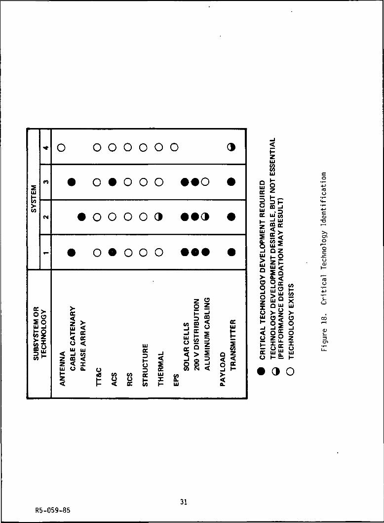
Besides the antenna development (whether cable-catenary or
phased-array) for the Band 1 and 2 satellite designs, other critical
technologies include the electrical power subsystem and the transmitters(Figure 18). Silicon solar cells of 2-mil thickness have been assumed
throughout. Cells of this thickness have been developed in 2 x 4 cm size.
From a cost standpoint, larger cells (e.g., 3x6 cm) of 2-mil thickness
are needed for an array generating on the order of 100 kW. To avoid exces-sive distribution losses, a 200-V distribution system is needed. This
level of distribution voltage is likely to be developed for Space Station.
There is also a need for lightweight, flexible cabling material, particu-larly with the large dimensions of the Band 1 geostationary satellite.
High-power transmitter development is crucial to Band 1 and 2 opera-
tion. Individual power amplifier outputs are about 10 kW for the Band 1geostationary satellites and the Band 2 Molniya satellites, and about 1 kWfor the 8-hour Band 1 system. The high reliability and high efficiency of
MOS-FET devices makes them the preferred power-amplifier technology,
provided the indicated power levels can be achieved.
27R5-059-85

N C3T LU5 Qr 2 NtO CM (OOJ 35
ui£
3?UJ t
00
o
oLUa.CO
DC UJ SLU t~ <a. Z LUO < CD
g5t
- ° S§ §i£i mm
oc 5< §cc s
< i33CO LU
\
+J•i—.ao
I00
s_o
O-aiocooa;
cu(OI/O
LO
a;
cn
28R5-059-85

u
LU
a.0
U
toc.cO)-Mc
<c
<cI
-oO)(/)(O
_c:Q_
(U
QJ
oa.O
O)
CO
OJ
3CD
R5-059-8529

01
OJ-l->to
(Oco
cooO)
XJc
CQ
o>3O)
30R5-059-85
-
n
UJ
fe
toM
r"
te .
SU
BS
YS
TE
M O
lT
EC
HN
OLO
GY
O O O O O
• 0 • O O
• o o o o
• o o o o
.oc< >UJ ^»- oc< oc0 < uj
_ UJ m CC< -I V) -3z 3 < jfZ < X oUl O Q. o 2H 08 CO CO OCz C o o £< f- < OC <o
o
0
3
o
_J
zocUJX
o
• •0
• •3
• €•
z 2o 5
SO
LAR
CE
LLS
200V
DIS
TR
IBU
T
ALU
MIN
UM
CA
BL
(/)
UJ
a
,
*
•
LOA
D
TR
AN
SM
ITT
ER
>
UJ
UJ
too
UJ — 3OC uj'wH d "JZ g CCUJ J* >Z -<fr w 5O UJ «_i O Z£ H2> ^ CUJO>
UJ
"O -JIZ <"I UJ U *~?! +Z\u ino ^ <^ —
^ tJ UJ LU
2 Si 5•- o5 o_J -I * _l< o£ oo z o z— = u. =L_ X rr X
E a£ aO H-£i I-
3 O
CDo0cuai
(Co
CO
3en
31R5-059-85
It is anticipated that the emphasis by the Japanese government on
solid-state devices for commercial broadcasting will propel MOS-FET devel-
opment to the power levels needed for Bands 1 and 2.
The evolutionary expectations for solid-state devices in Bands 1 and 2
do not apply to Band 3. There is no apparent commercial impetus for devel-
opment of MOS-FETs or other devices more efficient than current bipolar
transistors. Unless the low (30-percent) efficiency of these transistorsor the lower reliability of TWTs is acceptable, technology enhancement will
be necessary to achieve the required Band 3 transmitter power levels.
The need for technology development in the area of attitude control isuncertain at this point. This question should be resolved by further
analysis. Pending this determination, altitude control has been labeled asa critical technology in Figure 18.
5. SINGLE-CHANNEL SATELLITE BROADCAST SYSTEMS
The original set of broadcast requirements (as embodied in the
broadcast schedule of Figure 4) led to Band 1 satellite systems comprisingmany satellites of extremely large physical dimensions, with very large
costs. As a result, TRW was directed to perform an additional task todetermine the broadcast capability that can be derived from a single
satellite with sufficient power to broadcast just one voice channel. Threevalues of field strength- 300 vV/m (the baseline value), 150 uV/m, and 50
uV/m — were to be considered.
Six different orbits were examined. These include geostationary and
Molniya orbits, as well as subsynchronous orbits with 6-, 8-, and 12-hourperiods. The inclination of the 6- and 8-hour orbits is 28.5 degrees,while that of the 12-hour orbit is 37 degrees. The sixth orbit is referredto as a "triply-sync" orbit. It is a highly elliptical, sun-synchronous
orbit, with apogee of 7843 kilometers, perigee of 521 kilometers, andinclination of 116.6 degrees. The orbit period is 3 hours. Apogee is
placed at a latitude of 63.4 degrees, which is the maximum value achieved.
32R5-059-85

5.1 Satellite Visibility
Visibility for a geostationary satellite is simply described. The
visible region is shown in Figure 19 as a function of latitude and longi-tudinal offset, for a minimum elevation angle of 20 degrees. Visibility
periods for a satellite in Molniya orbit are immediately evident from a set
of instantaneous visibility contours. Visibility contours valid for either
of two consecutive 12-hour orbits are shown in Figure 20. The only dis-tinction between the two orbit passes is that the longitudinal reference(i.e., the longitude of apogee) is shifted by 180 degrees.
Satellite visibility for each open contour in Figure 20 (e.g., for t =
4 hr) extends to all points above that contour. Visibility for the closedcontours (e.g., t = 5 hr) is restricted to those points within the contour.
Continuous satellite visibility for the period (t t,,) requires that theobserver be located above or within all open or closed contours, respec-
tively, for times between t^ and t2< Visibility regions for variousminimum periods are indicated in Figure 20.
The triply-sync orbit offers the possibility of several significant(from a broadcast standpoint) visibility periods per day. Moreover, these
visibility periods occur at the same local time each day. Figure 21 showsthe period of visibility for three different latitudes as a function of
displacement from the longitude of apogee. Because of the 3-hour orbitperiod, a given latitude is crossed, in either the north-south or south-
north direction, at a longitudinal separation of 45 degrees on successiveorbits. Therefore, dividing the longitudinal span over which the visibil-ity period is approximately constant by 45 degrees gives the number of
successive orbits on which this degree of visibility is realized.
Satellite visibility is summarized below for the three values ofobserver latitude. For a latitude of 20 degrees, visibility during onepass in the middle of the sequence will be less than 30 minutes.
Latitude Period of Number(Degrees) Visibility (Min) of Passes
60 50 5
40 50 4
20 30 6
33R5-059-85

o>fl3
S_
Ca
to
O0)
CD
O)
3cn
UI V)O *"D £
R5-059-8534

COUIUJtrOuiQ
1/5U.U.o
ZQ3
5o
.5c:'o
to-ao
O)D.
d)
toGO
OCVJ
O)s_3CT)
§ s
Q UI3 uiHtt^~ ill
R5-059-8535

°0CO
8 5)in"~ 111
cco
S U4O
LU
2 U
"8
OOCu.
o
I1I
Q.
s-
5-o
S-0)Q.
«Sc
CM
Oli.
cn
Oin o oCM
36R5-059-85

Visibility of a satellite in subsynchronous orbit will be described asa function of observer latitude and longitudinal separation from the satel-
lite ascending node. For a 6-hour orbit, there can be as many as three
separate visibility periods daily; for an 8-hour orbit, two visibilityperiods; and for a 12-hour orbit, only one visibility period. Visibilityperiods for the three orbits are shown in Figures 22-24, for an observerlocated at the longitude of the ascending node. Visibility is consideredonly in multiples of 1/2-hour. In extreme cases, therefore, the visibility
periods may be understated by nearly 1 hour.
Because of the wide range of required field strengths and the need for
only a single voice channel, suitable orbital transfer vehicles (OTVs)range from the Centaur class to the PAM-A. In addition to these two OTVs,
a custom bipropel 1 ant second stage was considered. For each of the 18
orbit/field strength combinations, a representative set of satellite char-
acteristics was determined in conjunction with the choice of an appropriateOTV. The results are shown in Figure 25.
Since no antenna beamwidth is specified, a tradeoff exists between
antenna aperture and RF power. The approach adopted is to minimize theantenna aperture. The resulting beamwidth is indicated in each case. For
the geostationary, Molniya, and triply-sync orbits, the aperture refers to
a reflector type of antenna. For the three circular, subsynchronous
orbits, the aperture size is the dimension of a phased array.
The satellite weights in all but three cases reflect the benefits of
advanced technology, circa 1995. For the 6-, 8-, and 12-hour orbits and afield strength requirement of 50 pV/m, the satellite weights reflect current
technology. In all three cases, the antenna is of modest size. For the 6-and 8-hour orbits, the 11-meter aperture implies a 2 by 2 phased array.
Because the triply-sync orbit is confined to a radiation belt
encircling the earth, silicon solar cells cannot be used. The three
satellites designed for this orbit use a GaAs concentrator array, which isrelatively impervious to radiation. Because of the considerable weight of
this technology, fully half the satellite weight in each case is attribut-able to the electrical power subsystem.
37R5-059-85

«*N
00
* .N JSUlQoZ wf
azi <Mz ™Ul
< 00 5 "S o?= „_ UJ 00
o 9— D1- t
1 z_l ^
s 2«b f «+
• •
§
s
o00
§
go(O
o<o
g
oU)
§ oCO
oCO
8
8
o
':V::
O
HI V.3 uD UJHOC
0
••: •:
O
•
O
o
°
oCM
O
.* .' -.
o«?
?
0
o
o
?
o
15
o
o00
o00
?
o
CM
CM<N
os
00
(O
oc
*t O? X
UlCM 5
O (/)«- ocUl_
W z
O
(O
CJ
s-3O
S_O
Ol
O)
OOIo;en
c/o
C\JCM
O)
3CD
38R5-059-85

o o o o o o o o o* - w p
o o
N
NN
o
00
oo „-N ™UlOi *r-0z5 .,Z i-Ul
< 0
« | "
» "• M-» Ul *
o §
1 Z1 /^
o Zj— <4 V
O
'!'jv:*•>!";
-. ...
N
MM
OCM
CO
CO
*~ COccD
* X2Ul
CN 5
O CO
Ul_
o
o
s_os_to3O
o
30
CO!_
0)
0)
0)
en
CMo>3
o o of » w u > o o o o o o o o o o o
IUCOO ui
39R5-059-85

S o o o o o
X
P4S
oCM
00
ooCD
It 1=111OoCD
1 ™z «-UJ
%. o
• E .z §— D
1 Z"1 /
§ 3 ^
• •
(M
O
• .:;:•::
:•••: :•:•
<N
CM(SI
N
CO
(O
oc
•«• o? I
UJCM 5
_J
O CO«- oc
UJ_
•*
w
o
S-os_re
r—3O
•r—O
s-3O
ICM
o<4-
>^
cu
01-l-»ret/5
I(U
enc
(1)i-3CD
* - ( N C O « i r >
UJ COQ UJD "
UJ
40R5-059-85

UJ
_i O fflu H3d<sCO
UJ CCU uj
ceo i111 Q. £S> u.< cc
< UJ2pC
m 1- 5ticce
§1z- JEtj Q-2!o = a5 UJ § UJ^ CJ S Q_^5 l
O J"UJ ffi
Q<o
tooysr*" _J — ' •tf\ V_ -k ^
^ o "**"
< 1-a.
. oc
OR
BIT
AL
TR
AN
SF
EI
VE
HIC
LE
X
301iyui>1 1 ff T_i c i
Ecco
COot— "
*"
o
CO
in
oo
inCO
CE
NT
AU
R
0oCO
0mo
T—inr-**™
Oin
COCO
CNCN^—
O0oinCO
CE
NT
AU
R
oin
0UJCJ
|
•"
in
o
0oCN
Oooo"
CU
ST
OM
BIP
RO
P
oin
0UJO
CNO)T"
co"*~
enin
oCO
00CO
ooo.inCO
CE
NT
AU
R
§CO
OL
NIY
A
s
iCO**"
COCO
CNCD
.j.'^»-
O0oin"CO
CE
NT
AU
R
oin
VA
INIO
I
s
CNOco_f»,"
00CN
CNCO
O00CN
Oooo"
CU
ST
OM
BIP
RO
P
oin
O5
1en
in
£
.CO
oo0o"CO
CU
ST
OM
BIP
RO
P
ooCO
_l o
Hco
enCMCOen"
*••
COCO
CM(<
Oo
o"CO
CU
ST
OM
BIP
RO
P
oin
hcz >Hco
COCOin"
<Dcc(O
I0)
COCO
oo
o-CN
o
sO)
4->(Jns
10
Ol
O)-(->IO
0)
H3 >,-(-> •!->C -i-O) r—</) -i-O) -OS_ (Oa. a.CU «3a: o
inCNJ
CDs_3
oin
41R5-059-85

LU
tH_J X —_i a CQ£Lu=J
CO
UJ CCa LU<5^cco5UJ 0. ;£> U.< CC
< UJz °-Sfcsi_ CC £.? UJ
< °"
t£ f"j^Q-d o = a< LU g UJ>osaD <~~"0 mIjj CO
O<o»o"jsto>-o —
< H-a.
. CC-Juj UJ< u. -Ji-co oCD z 3;CC<LUO tt >
H
X« -«?0 £-> 2 -CUJ £ >
u. cc 3-^—CO
1-mcc0
CO
co_en
CMCO
5
oin
o§
s
US
TO
MIP
RO
P
U CO
o0CO
CCX(O
CDCMinCO*
CMCO
£
0ot—
o§00CO
US
TO
MIP
RO
P
U 03
Oin*~
CCX(O
*oo"*
inCO
-
oo
oo
co"
sa.
oin
ccX(O
CMOCO
oo"
,—CO
$
0U)
o§CM
US
TO
MIP
RO
P
U CO
0on
ccX00
O)o
r»"
,_CO
^
oo
o0
oo"CO
US
TO
MIP
RO
P
U CO
0in
ccX00
*oin°l"*
oin
-
o
^~
o0in5
iSa.
oin
ccX00
CM
§O
*—CO
in<o
oin
o
in
US
TO
MIP
RO
P
U CO
ooCO
ccXCM
CMCMCMoo"
,—CO
COCM
00
oi00
US
TO
MIP
RO
P
U CO
oin
ccXCM*~
*o§in
iin
en
oCO
oo
CMU
ST
OM
IPR
OP
U CO
0in
ccXCM*~
0
ozX(JLU1-1_r^
LUccCC
UzoaLUCO
<l)ccto
(_J1
a>01
OO
s-oH-
coO
00
CU
a(T3
rQ •* —
C3 <U
OJ C+J •!-
•i— 4-Ji— Ci— 0
i _> v^^
(BOO N
>"s:i —<O * D
CM
> 4->•i— (O
<O >>•*-> •*-*C •!—
ai i—00 T-
O) JDS- (Oa. a.CD (Oo: o
•Lf)C>J
OJ
3
*-"•r—U_
CO
R5-059-8542