Embed Size (px)
Citation preview
Juliette Marais INRETS – LEOST [email protected]
Satellite propagation analysis in a masking environment for GNSS applications
1. INTRODUCTION
Most of the applications for localization and navigation in the field of transport use satellite systems (such as GPS, GLONASS, or the future European GALILEO system) [1][2]. They are now widespread all over the world. Moreover, every prediction of their evolutions in the next years, especially with the development of the European Galileo system, agree on a large increase of these products and of new services. They have been generally developed for road applications. Some are easily transposable in a railway environment for non-safety applications (fleet management...) [3]. Nevertheless, the development of critical applications concerning safety such as railway control and command, relies on the accurate determination of many parameters for which system availability is a crucial point [4][5]. Furthermore, there is a growing need to develop low-cost, safe localization and navigation systems, such as the core of a train command-control system on low density railway lines, or for automated highway applications.
The performances and reliability of the localization system are strongly related to parameters such as localization accuracy, receiver acquisition rate, availability and integrity of the signals. The overall availability of the system is defined as the percentage of time that the services of the system are usable [6]. For satellite-based systems, the availability depends on several criteria such as the number of visible satellites, their relative position within the constellation, the radio electric coverage of the constellation and the health status of these satellites which have an impact on the integrity of the signals.
Availability, accuracy and integrity are not always satisfactory for transport applications. The availability of most satellite-based localization processes of terrestrial mobiles is considerably degraded in transport environments because of significant mask effects. Indeed, a classical receiver requires a minimal number of four satellites for triangulation. That will not always be reached in an urban canyon or in railway cuttings. Moreover the satellite states of reception impact on accuracy and integrity. Most of the localization and navigation systems in operation today compensate the lack of availability of the satellite constellation [7][8][9] by adding the so-called “augmentation” solutions. This consists of a sensor fusion approach [10] between the information given by the satellite receiver and others such as broadcasting of local geographic information, map matching [11][12], analysis of mechanical information (gyroscope, speedometer…) [13] and sometimes information given by terrestrial localization beacons judiciously deployed along the vehicle trajectory. For the development of safe localization applications for road and railway transport, it is in particular necessary to be able to predict the availability of the satellite constellation with an evaluation tool in order to simulate the overall system. The major goal of such a tool would be to provide system safety demonstrations with accurate availability parameters.
A real application : The LOCOPROL project
Today, every national railway administrations of the EU have developed its signalling as well as train positioning systems. In the existing systems, the train positioning is achieved by track circuits and/or axle counters, which check if a rail route is free or occupied by
vehicles. A lot of sensors are today installed on tracks. This leads to very high installation and maintenance costs. An other problem today is the existence of incompatible systems between countries, thus, high costs again when engines have to carry equipment that match with different signalling systems. The European Train Control System (ETCS) is intended to develop a common standard, improving also operating efficiency and reducing costs.
As the ETCS is dedicated to high-speed lines, with different cost objectives, UIC has started a specification project for the new levels of ERTMS/ETCS, called ETCS-LC where LC stands for Low Cost. The ETCS-LC will be applicable for other lines like national main lines or regional/secondary lines, with a lower traffic density, representing about 20% of the European lines. The possibilities of GNSS based train location are seriously considered in the ETCS-LC because :
• The systems doesn’t know any frontiers, • No equipment is needed on tracks (benefit : less maintenance needs and no
vandalism damages), • The service is continuous, • The GNSS achieve an absolute position and do not drift (as the odometer does), • Facility to install and integrate receivers on trains.
For these reasons, in the context of the European research program and with the development of the EGNOS and ultimately the Galileo European GNSS system, the European Commission (EU) and the European Space Agency (ESA) are encouraging efforts in the development of new control-command systems based on satellite technologies.
Satellite based localisation systems are already in deployment for non-safety railway applications [14]. The major drawbacks for a safety use of these systems are :
• the lack of availability previously mentioned, Requirements of non-safety applications fit in general with GNSS specifications. For example, a container localization does not need to be localized continuously or more than one time every 10 or 15 minutes. Moreover, if the inaccuracy of the information is 50 meters, the service can be assured. That is not the case, of course, of safety related applications. • a lack of integrity information (the position can be computed but not safely).
Today, GPS does not give any integrity information on the transmitted message. In practical, that means that a receiver can use a signal coming from a failing satellite before the control segment will flag the satellite as unsafe. This is today one of the major challenges of GNSS for railways. A part of the answer will be given with the EGNOS integrity information. EGNOS is the first step towards GALILEO, the European GPS. EGNOS is composed of 3 geostationary satellites, used as an augmentation of GPS solution. Because of their geostationary status, the satellites will be viewed with a low elevation angle (30°) at our latitudes and the availability of EGNOS signals will not be guaranteed in high-elevated environments [15]. This has been a major challenge for the LOCOPROL consortium, in order to develop a fail-safe control-command system based on satellite navigation. In § 4.1 we will present how we have used PREDISSAT in the LOCOPROL project.
2. SATELLITE-BASED NAVIGATION SYSTEMS
2.1. Fundamentals Satellite-based positioning methods are funded on the propagation time measurement
and a triangulation principle. The best-known Global Navigation Satellite Systems (GNSS) is today the American Global Position System (GPS). But a Russian constellation does also exist : GLONASS, that should survive to the severe maintenance difficulties encountered the last decade but which is today only used as a complementary system. In the next ten years, Europe will have its own system called GALILEO. Both of these systems are composed of non-geostationary satellites.
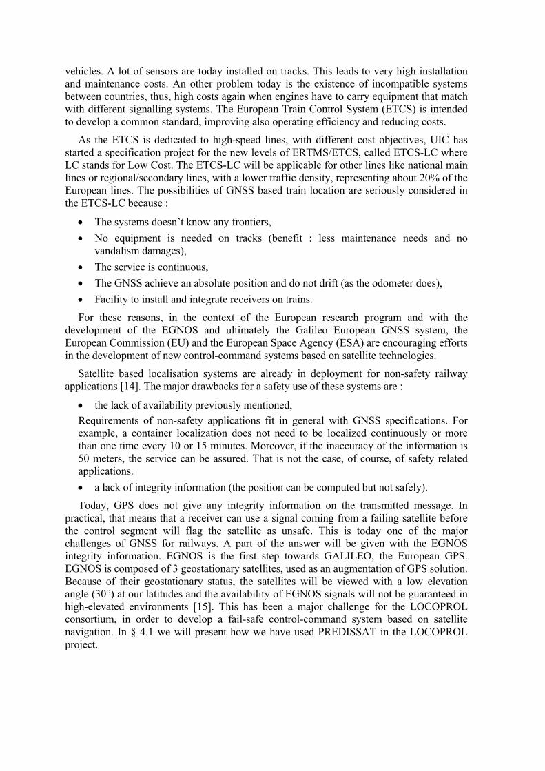
The GPS constellation, property of the US Department of Defence, was declared operational at the end of 1993. The constellation is composed of 24 satellites (at least) – 4 in each of the six circular orbits with inclination of 55 deg [16] as represented figure 1, against 30 satellites for GALILEO - distributed over three planes in Medium Earth Orbit (MEO). The service is free and available for every owner of an adapted receiver. Each of the satellites broadcasts a continuous coded signal. The code is different for every satellite. The receiver is then able to separate one message from another and to identify the transmitter identity.
The message contains :
• ephemeris that allow to determine the satellite position in a terrestrial reference system,
• and the time “t” of the message emission.
The receiver decodes the messages of visible satellites and, knowing the time of arrival and the propagation speed of the signal, extracts the distance between the satellite and the receiver “d” called pseudo-distance. The receiver is then positioned on a sphere centred on the satellite with radius d. Intersection of three spheres obtained from three received satellites allows the receiver to compute its position as represented figure 2 (in practice, a fourth one is used to solve the time ambiguity).
Figure 1. GPS Constellation.
Figure 2. Triangulation principle.
2.2. The drawbacks/difficulties in a masking environment
2.2.1. Propagation errors Today, the accuracy of the GPS system is around 10 meters. The major causes for the
inaccuracy are related to a bad estimation of the satellite-receiver distance due to [17] :
• signal availability function of time,
• bad geometry of the visible satellites, • propagation phenomena (ionospheric and tropospheric errors, multipath…), • ephemeris errors, • clock errors, • receiver errors (clock bias, noise…).
Models or dual frequency use permit to correct some of the propagation errors. Furthermore, some augmentations are developed, among which :
• DGPS (Differential-GPS) uses a base station that broadcast to local users the difference between its well-known coordinates and the computed position in order to obtain a better accuracy.
• GALILEO will broadcast “wide area” corrections via a geostationary satellite.
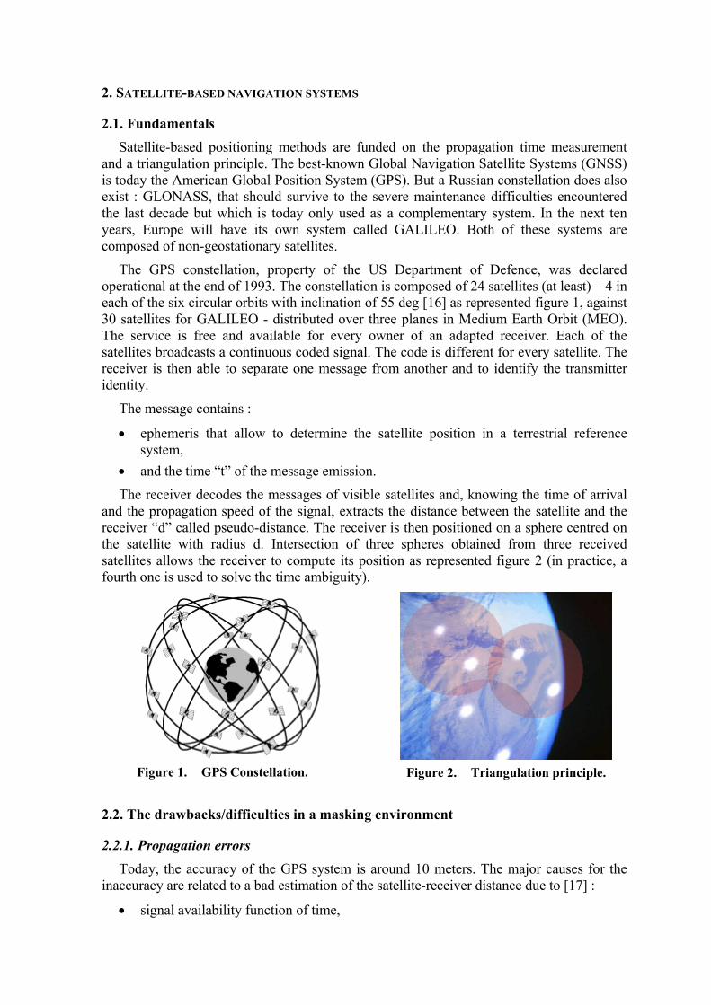
In any case, the position given by a satellite-based system relies on propagation time measurement (TOA Time Of Arrival). Hence, the environment of the antenna will play a major role because the propagation phenomena caused by the environment induce indirect propagation paths that introduce delays. In a typical canyon environment, the conditions of each satellite signal reception can be classified into three states. As presented in figure 3, they are :
• Direct reception when no obstacle occurs between satellite and receiver (Line Of Sight),
• Alternate path reception when the direct signal cannot be received and another one, received after multipath, is used as the only data for pseudo-range extraction. Considering results from [18] we assume that multipath is restricted to one reflection.
• Blocked reception when the signal is completely blocked and cannot be used.
Visible
Alternate path
Blocked
Figure 3. States of satellite reception.
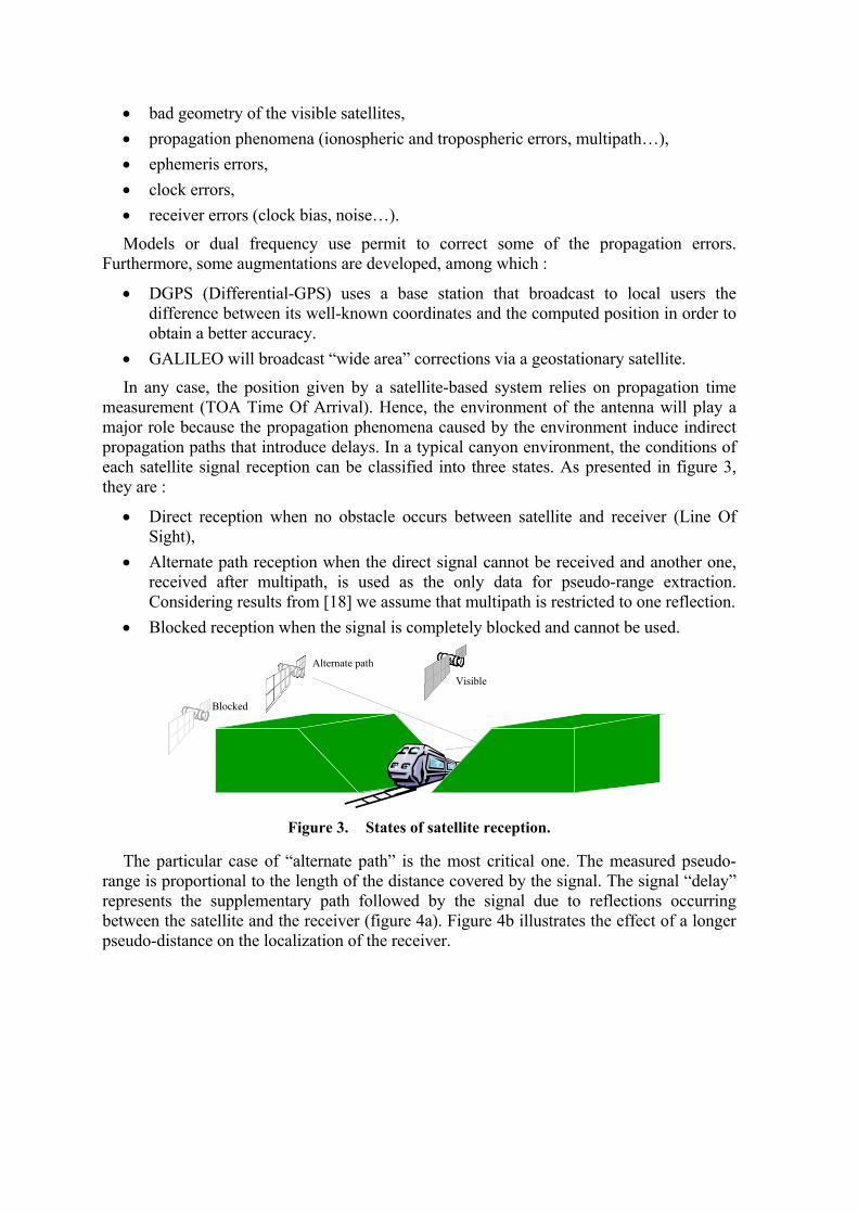
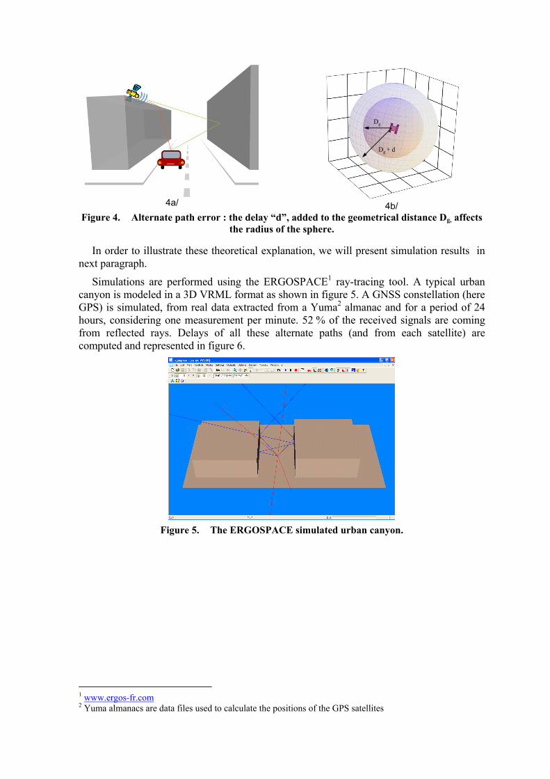
The particular case of “alternate path” is the most critical one. The measured pseudo-range is proportional to the length of the distance covered by the signal. The signal “delay” represents the supplementary path followed by the signal due to reflections occurring between the satellite and the receiver (figure 4a). Figure 4b illustrates the effect of a longer pseudo-distance on the localization of the receiver.
4a/
Dg
Dg + d
4b/
Figure 4. Alternate path error : the delay “d”, added to the geometrical distance Dg, affects the radius of the sphere.
In order to illustrate these theoretical explanation, we will present simulation results in next paragraph.
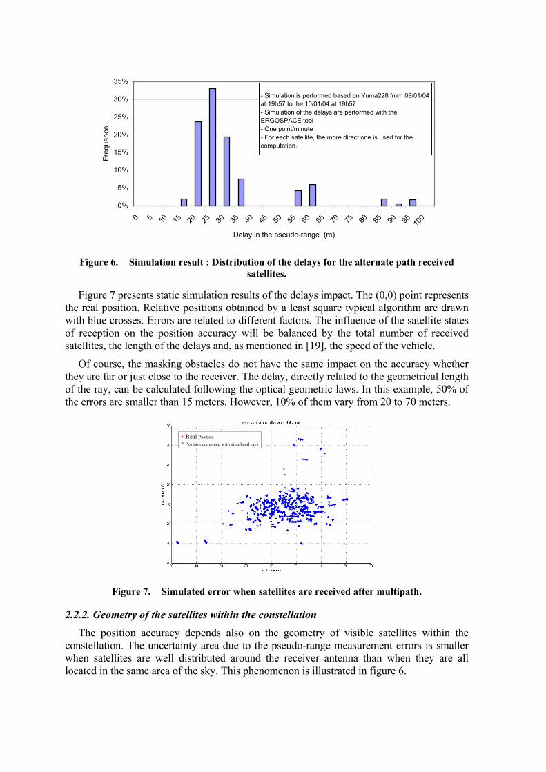
Simulations are performed using the ERGOSPACE1 ray-tracing tool. A typical urban canyon is modeled in a 3D VRML format as shown in figure 5. A GNSS constellation (here GPS) is simulated, from real data extracted from a Yuma2 almanac and for a period of 24 hours, considering one measurement per minute. 52 % of the received signals are coming from reflected rays. Delays of all these alternate paths (and from each satellite) are computed and represented in figure 6.
Figure 5.
The ERGOSPACE simulated urban canyon.
1 www.ergos-fr.com 2 Yuma almanacs are data files used to calculate the positions of the GPS satellites
0%
5%
10%
15%
20%
25%
30%
35%
0 5 10 15 20 25 30 35 40 45 50 55 60 65 70 75 80 85 90 95 100
Delay in the pseudo-range (m)
Freq
uenc
e- Simulation is performed based on Yuma228 from 09/01/04 at 19h57 to the 10/01/04 at 19h57- Simulation of the delays are performed with the ERGOSPACE tool- One point/minute- For each satellite, the more direct one is used for the computation.
Figure 6.
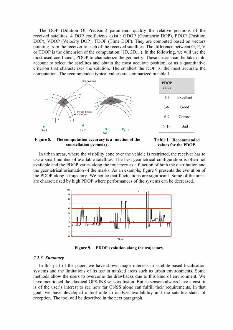
Simulation result : Distribution of the delays for the alternate path received satellites.
Figure 7 presents static simulation results of the delays impact. The (0,0) point represents the real position. Relative positions obtained by a least square typical algorithm are drawn with blue crosses. Errors are related to different factors. The influence of the satellite states of reception on the position accuracy will be balanced by the total number of received satellites, the length of the delays and, as mentioned in [19], the speed of the vehicle.
Of course, the masking obstacles do not have the same impact on the accuracy whether they are far or just close to the receiver. The delay, directly related to the geometrical length of the ray, can be calculated following the optical geometric laws. In this example, 50% of the errors are smaller than 15 meters. However, 10% of them vary from 20 to 70 meters.
Real Position * Position computed with simulated rays
+
Figure 7. Simulated error when satellites are received after multipath.
2.2.2. Geometry of the satellites within the constellation The position accuracy depends also on the geometry of visible satellites within the
constellation. The uncertainty area due to the pseudo-range measurement errors is smaller when satellites are well distributed around the receiver antenna than when they are all located in the same area of the sky. This phenomenon is illustrated in figure 6.
The DOP (Dilution Of Precision) parameters qualify the relative positions of the received satellites. 4 DOP coefficients exist : GDOP (Geometric DOP), PDOP (Position DOP), VDOP (Velocity DOP), TDOP (Time DOP). They are computed based on vectors pointing from the receiver to each of the received satellites. The difference between G, P, V or TDOP is the dimension of the computation (1D, 2D…). In the following, we will use the most used coefficient, PDOP to characterize the geometry. These criteria can be taken into account to select the satellites and obtain the most accurate position, or as a quantitative criterion that characterizes the solution. The smallest the DOP is, the most accurate the computation. The recommended typical values are summarized in table I.
User position
Pseudo-distance uncertainty
Sat 1 Sat 2Sat 1
Sat 2
Figure 8. The computation accuracy is a function of the constellation geometry.
PDOP value
Quality
1-3 Excellent
3-6 Good
6-9 Correct
≥ 10 Bad
Table I. Recommended values for the PDOP.
In urban areas, where the visibility cone over the vehicle is restricted, the receiver has to use a small number of available satellites. The best geometrical configuration is often not available and the PDOP varies along the trajectory as a function of both the distribution and the geometrical orientation of the masks. As an example, figure 9 presents the evolution of the PDOP along a trajectory. We notice that fluctuations are significant. Some of the areas are characterized by high PDOP where performances of the systems can be decreased.
0
1
2
3
4
5
6
7
8
9
10
09:41:17 09:4
1:32 09:41:47 09:4
2:02 09:42:17 09:4
2:32 09:42:47 09:4
3:02 09:43:17 09:4
3:3209:43:47
09:44:02
09:44:17
09:44:32
09:44:47
09:45:02
09:45:17
09:45:32
09:45:47
09:46:02
09:46:17
09:46:32
09:46:47
09:47:02
09:47:17
09:47:32
09:47:47
09:48:02
09:48:17
09:48:32
09:48:47
09:49:02
09:49:17 09:4
9:32 09:49:47
Time
Figure 9. PDOP evolution along the trajectory.
2.2.3. Summary In this part of the paper, we have shown major interests in satellite-based localisation
systems and the limitations of its use in masked areas such as urban environments. Some methods allow the users to overcome the drawbacks due to this kind of environment. We have mentioned the classical GPS/INS sensors fusion. But as sensors always have a cost, it is of the user’s interest to see how far GNSS alone can fulfill their requirements. In that goal, we have developed a tool able to analyze availability and the satellite states of reception. The tool will be described in the next paragraph.
3. OUR APPROACH : THE PREDISSAT TOOL A method to predict the availability of a satellite system along a fixed trajectory could be
simply to run a large number of times along this railway line or road in order to compute statistical values of the GPS satellite visibility as a function of time and space. However, this method needs a huge quantity of data particularly in the case of non-geostationary constellations and is obviously time consuming. This is the reason why we did not chose it.
In a guided-transportation context, we assume that the environment of the vehicle will not change from one travel or mission to another on the same line. The PREDISSAT tool (PREDIctive Software for Satellite Availability in the field of Transport) allows us to determine the number of satellites that will be received and available for localization, at any time and anywhere along a given trajectory. The tool includes a simulation stage for the knowledge of the satellite positions relying on the STK3 (Satellite Tool Kit) software and an image-processing stage based on a video record of the optical environment surrounding the receiving antenna. This is performed in order to extract the satellites that could be received effectively.
The optical approach allows us to define an “optical horizon line” such that a satellite is “visible” above it, and “blocked” under it. Nevertheless, as expressed in §2, satellites can be received without direct ray. The satellite elevation is then under the optical mask horizon line and the signal is received by a reflected ray. As suggested in [20]-[22] and illustrated in figure 3, we classify the satellite signal into three states: Direct, Alternate path, Blocked.
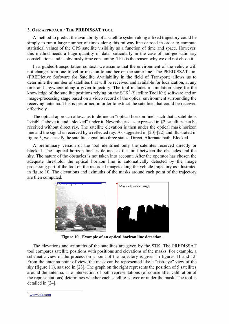
A preliminary version of the tool identified only the satellites received directly or blocked. The “optical horizon line” is defined as the limit between the obstacles and the sky. The nature of the obstacles is not taken into account. After the operator has chosen the adequate threshold, the optical horizon line is automatically detected by the image processing part of the tool on the recorded images along the vehicle trajectory as illustrated in figure 10. The elevations and azimuths of the masks around each point of the trajectory are then computed.
Mask elevation angle
Figure 10.
Example of an optical horizon line detection.
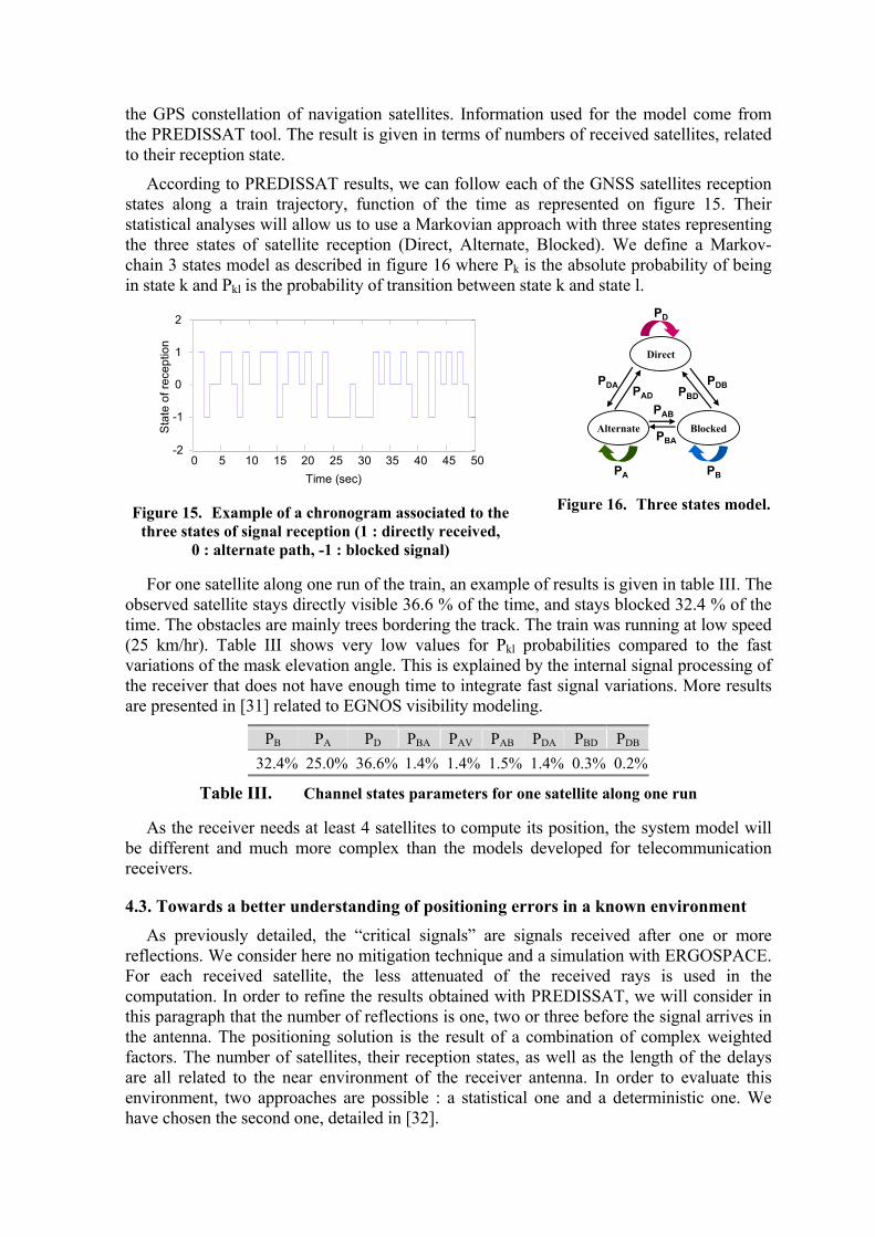
The elevations and azimuths of the satellites are given by the STK. The PREDISSAT tool compares satellite positions with positions and elevations of the masks. For example, a schematic view of the process on a point of the trajectory is given in figures 11 and 12. From the antenna point of view, the mask can be represented like a “fish-eye” view of the sky (figure 11), as used in [23]. The graph on the right represents the position of 5 satellites around the antenna. The intersection of both representations (of course after calibration of the representations) determines whether each satellite is over or under the mask. The tool is detailed in [24].
3 www.stk.com
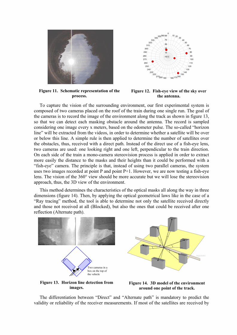
Figure 11. Schematic representation of the process.
-10
10
30
50
70
900
10 20 30
40 50
60 70
80 90 100
110 120
130 140
150 160 170 180 190200210
220230
240250
0
0
0
0
310320
330340
350360
26
27
280
29
30
Figure 12. Fish-eye view of the sky over the antenna.
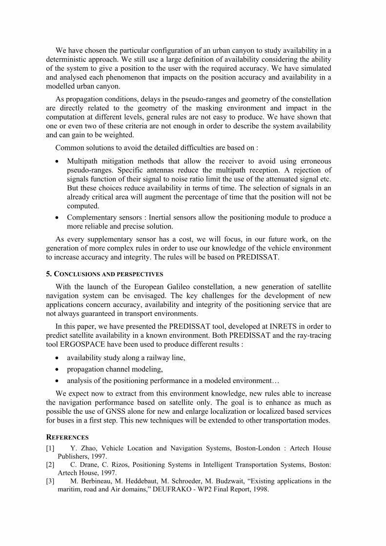
To capture the vision of the surrounding environment, our first experimental system is composed of two cameras placed on the roof of the train during one single run. The goal of the cameras is to record the image of the environment along the track as shown in figure 13, so that we can detect each masking obstacle around the antenna. The record is sampled considering one image every x meters, based on the odometer pulse. The so-called “horizon line” will be extracted from the videos, in order to determine whether a satellite will be over or below this line. A simple rule is then applied to determine the number of satellites over the obstacles, thus, received with a direct path. Instead of the direct use of a fish-eye lens, two cameras are used: one looking right and one left, perpendicular to the train direction. On each side of the train a mono-camera stereovision process is applied in order to extract more easily the distance to the masks and their heights than it could be performed with a “fish-eye” camera. The principle is that, instead of using two parallel cameras, the system uses two images recorded at point P and point P+1. However, we are now testing a fish-eye lens. The vision of the 360° view should be more accurate but we will lose the stereovision approach, thus, the 3D view of the environment.
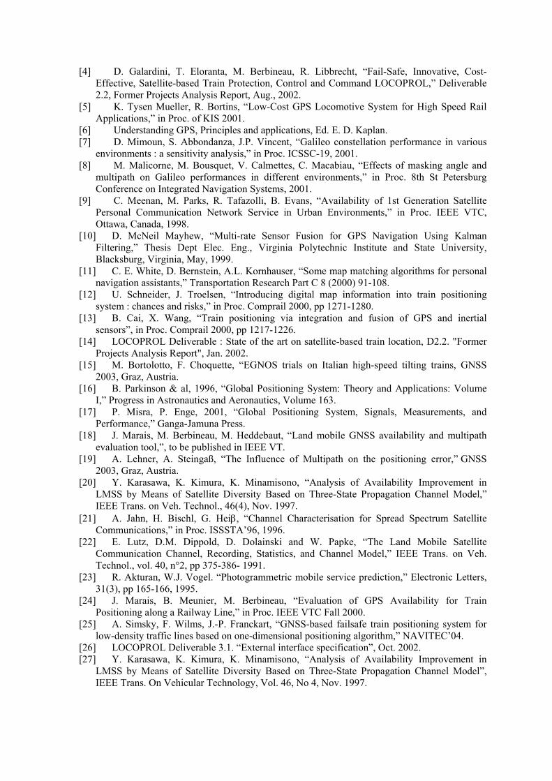
This method determines the characteristics of the optical masks all along the way in three dimensions (figure 14). Then, by applying the optical geometrical laws like in the case of a “Ray tracing” method, the tool is able to determine not only the satellite received directly and those not received at all (Blocked), but also the ones that could be received after one reflection (Alternate path).
Two cameras in a box on the top of the vehicle
Figure 13. Horizon line detection from images.
trajectoire
P
Figure 14. 3D model of the environment around one point of the track.
The differentiation between “Direct” and “Alternate path” is mandatory to predict the validity or reliability of the receiver measurements. If most of the satellites are received by

alternate paths, the user should consider that the probability that the receiver position has deviated from the correct position is high.
4. APPLICATIONS OF THE PREDISSAT TOOL The tool has been applied for different types of applications. In European projects, the
goal of its use was to perform an analysis of availability along dedicated (railway) lines. But the tool, completed with ray tracing tools, has also been applied in order to perform channel propagation models or for a better understanding of the positioning errors in known environments. We will illustrate these uses in this paragraph.
4.1. Analysis of satellite availability in a real railway environment As introduced in the beginning of this paper, the LOCOPROL4 (LOw COst satellite
based train location system for signalling and train PROtection for Low-density traffic railway lines) project intends to develop a new cost-effective satellite based fail-safe and innovative train protection, control and command system, specifically to be used on railways with low traffic density. The fail-safe constraint has been a high input in the design of a new satellite-based localisation algorithm described in [27]. The PREDISSAT tool has been used first to determine, along the test track, if the minimum required 4 satellites could be received at anytime, then, in order to characterise the reception states of the GNSS satellites along a railway line and to evaluate the probability of alternate paths for a global view of the multipath conditions. The probability Pn,m to get signals from n satellites of which m are masked has been computed.
An example of the presented results is summarized on table II [28]. It represents the probability that m satellites from n received are received via alternate path for a specific train mission considering that the mask elevation angle is 20° all along the track.
m : masked satellites 0 1 2 3 4
6 11 % 1 % 0 7 2 % 6 % 1 % 1 % 8 0 7 % 10 % 3 % 1 % 9 4 % 10% 16 % 4 % 5 % n
: rec
eive
d sa
telli
tes
10 0 4 % 7 % 3 % 3 %
Table II. Simulated probabilities that m satellites from n received are received via alternate path (mask elevation angle around the antenna : 20°).
The impact has been the enhancement of the robustness of the satellites choice and the development of a redundancy principle regarding the high probability of the alternate path signals.
4.2. Satellite propagation path model definitions The influence of the satellite states of reception on the position accuracy is balanced by
environmental factors... A good knowledge of the satellite channel behaviour allows us to assess the performance of the system. Statistics of Land Mobile Satellite Channel are presented in the literature using the Markov-chain based model [29][30]. Results are extracted from measurements or more often from simulations. We applied this approach to
4 www.locoprol.org
the GPS constellation of navigation satellites. Information used for the model come from the PREDISSAT tool. The result is given in terms of numbers of received satellites, related to their reception state.
According to PREDISSAT results, we can follow each of the GNSS satellites reception states along a train trajectory, function of the time as represented on figure 15. Their statistical analyses will allow us to use a Markovian approach with three states representing the three states of satellite reception (Direct, Alternate, Blocked). We define a Markov-chain 3 states model as described in figure 16 where Pk is the absolute probability of being in state k and Pkl is the probability of transition between state k and state l.
0 5 10 15 20 25 30 35 40 45 50-2
-1
0
1
2
Time
Sta
te o
frec
eptio
n
Time (sec) Figure 15. Example of a chronogram associated to the
three states of signal reception (1 : directly received, 0 : alternate path, -1 : blocked signal)
Blocked
Direct
PB
PDBPBD
Alternate
PD
PA
PBA
PAB
PADPDA
Figure 16. Three states model.
For one satellite along one run of the train, an example of results is given in table III. The observed satellite stays directly visible 36.6 % of the time, and stays blocked 32.4 % of the time. The obstacles are mainly trees bordering the track. The train was running at low speed (25 km/hr). Table III shows very low values for Pkl probabilities compared to the fast variations of the mask elevation angle. This is explained by the internal signal processing of the receiver that does not have enough time to integrate fast signal variations. More results are presented in [31] related to EGNOS visibility modeling.
PB PA PD PBA PAV PAB PDA PBD PDB 32.4% 25.0% 36.6% 1.4% 1.4% 1.5% 1.4% 0.3% 0.2%
Table III. Channel states parameters for one satellite along one run
As the receiver needs at least 4 satellites to compute its position, the system model will be different and much more complex than the models developed for telecommunication receivers.
4.3. Towards a better understanding of positioning errors in a known environment As previously detailed, the “critical signals” are signals received after one or more
reflections. We consider here no mitigation technique and a simulation with ERGOSPACE. For each received satellite, the less attenuated of the received rays is used in the computation. In order to refine the results obtained with PREDISSAT, we will consider in this paragraph that the number of reflections is one, two or three before the signal arrives in the antenna. The positioning solution is the result of a combination of complex weighted factors. The number of satellites, their reception states, as well as the length of the delays are all related to the near environment of the receiver antenna. In order to evaluate this environment, two approaches are possible : a statistical one and a deterministic one. We have chosen the second one, detailed in [32].
We have chosen the particular configuration of an urban canyon to study availability in a deterministic approach. We still use a large definition of availability considering the ability of the system to give a position to the user with the required accuracy. We have simulated and analysed each phenomenon that impacts on the position accuracy and availability in a modelled urban canyon.
As propagation conditions, delays in the pseudo-ranges and geometry of the constellation are directly related to the geometry of the masking environment and impact in the computation at different levels, general rules are not easy to produce. We have shown that one or even two of these criteria are not enough in order to describe the system availability and can gain to be weighted.
Common solutions to avoid the detailed difficulties are based on :
• Multipath mitigation methods that allow the receiver to avoid using erroneous pseudo-ranges. Specific antennas reduce the multipath reception. A rejection of signals function of their signal to noise ratio limit the use of the attenuated signal etc. But these choices reduce availability in terms of time. The selection of signals in an already critical area will augment the percentage of time that the position will not be computed.
• Complementary sensors : Inertial sensors allow the positioning module to produce a more reliable and precise solution.
As every supplementary sensor has a cost, we will focus, in our future work, on the generation of more complex rules in order to use our knowledge of the vehicle environment to increase accuracy and integrity. The rules will be based on PREDISSAT.
5. CONCLUSIONS AND PERSPECTIVES
With the launch of the European Galileo constellation, a new generation of satellite navigation system can be envisaged. The key challenges for the development of new applications concern accuracy, availability and integrity of the positioning service that are not always guaranteed in transport environments.
In this paper, we have presented the PREDISSAT tool, developed at INRETS in order to predict satellite availability in a known environment. Both PREDISSAT and the ray-tracing tool ERGOSPACE have been used to produce different results :
• availability study along a railway line, • propagation channel modeling, • analysis of the positioning performance in a modeled environment…
We expect now to extract from this environment knowledge, new rules able to increase the navigation performance based on satellite only. The goal is to enhance as much as possible the use of GNSS alone for new and enlarge localization or localized based services for buses in a first step. This new techniques will be extended to other transportation modes.
REFERENCES [1] Y. Zhao, Vehicle Location and Navigation Systems, Boston-London : Artech House
Publishers, 1997. [2] C. Drane, C. Rizos, Positioning Systems in Intelligent Transportation Systems, Boston:
Artech House, 1997. [3] M. Berbineau, M. Heddebaut, M. Schroeder, M. Budzwait, “Existing applications in the
maritim, road and Air domains,” DEUFRAKO - WP2 Final Report, 1998.
[4] D. Galardini, T. Eloranta, M. Berbineau, R. Libbrecht, “Fail-Safe, Innovative, Cost-Effective, Satellite-based Train Protection, Control and Command LOCOPROL,” Deliverable 2.2, Former Projects Analysis Report, Aug., 2002.
[5] K. Tysen Mueller, R. Bortins, “Low-Cost GPS Locomotive System for High Speed Rail Applications,” in Proc. of KIS 2001.
[6] Understanding GPS, Principles and applications, Ed. E. D. Kaplan. [7] D. Mimoun, S. Abbondanza, J.P. Vincent, “Galileo constellation performance in various
environments : a sensitivity analysis,” in Proc. ICSSC-19, 2001. [8] M. Malicorne, M. Bousquet, V. Calmettes, C. Macabiau, “Effects of masking angle and
multipath on Galileo performances in different environments,” in Proc. 8th St Petersburg Conference on Integrated Navigation Systems, 2001.
[9] C. Meenan, M. Parks, R. Tafazolli, B. Evans, “Availability of 1st Generation Satellite Personal Communication Network Service in Urban Environments,” in Proc. IEEE VTC, Ottawa, Canada, 1998.
[10] D. McNeil Mayhew, “Multi-rate Sensor Fusion for GPS Navigation Using Kalman Filtering,” Thesis Dept Elec. Eng., Virginia Polytechnic Institute and State University, Blacksburg, Virginia, May, 1999.
[11] C. E. White, D. Bernstein, A.L. Kornhauser, “Some map matching algorithms for personal navigation assistants,” Transportation Research Part C 8 (2000) 91-108.
[12] U. Schneider, J. Troelsen, “Introducing digital map information into train positioning system : chances and risks,” in Proc. Comprail 2000, pp 1271-1280.
[13] B. Cai, X. Wang, “Train positioning via integration and fusion of GPS and inertial sensors”, in Proc. Comprail 2000, pp 1217-1226.
[14] LOCOPROL Deliverable : State of the art on satellite-based train location, D2.2. "Former Projects Analysis Report", Jan. 2002.
[15] M. Bortolotto, F. Choquette, “EGNOS trials on Italian high-speed tilting trains, GNSS 2003, Graz, Austria.
[16] B. Parkinson & al, 1996, “Global Positioning System: Theory and Applications: Volume I,” Progress in Astronautics and Aeronautics, Volume 163.
[17] P. Misra, P. Enge, 2001, “Global Positioning System, Signals, Measurements, and Performance,” Ganga-Jamuna Press.
[18] J. Marais, M. Berbineau, M. Heddebaut, “Land mobile GNSS availability and multipath evaluation tool,”, to be published in IEEE VT.
[19] A. Lehner, A. Steingaß, “The Influence of Multipath on the positioning error,” GNSS 2003, Graz, Austria.
[20] Y. Karasawa, K. Kimura, K. Minamisono, “Analysis of Availability Improvement in LMSS by Means of Satellite Diversity Based on Three-State Propagation Channel Model,” IEEE Trans. on Veh. Technol., 46(4), Nov. 1997.
[21] A. Jahn, H. Bischl, G. Heiβ, “Channel Characterisation for Spread Spectrum Satellite Communications,” in Proc. ISSSTA’96, 1996.
[22] E. Lutz, D.M. Dippold, D. Dolainski and W. Papke, “The Land Mobile Satellite Communication Channel, Recording, Statistics, and Channel Model,” IEEE Trans. on Veh. Technol., vol. 40, n°2, pp 375-386- 1991.
[23] R. Akturan, W.J. Vogel. “Photogrammetric mobile service prediction,” Electronic Letters, 31(3), pp 165-166, 1995.
[24] J. Marais, B. Meunier, M. Berbineau, “Evaluation of GPS Availability for Train Positioning along a Railway Line,” in Proc. IEEE VTC Fall 2000.
[25] A. Simsky, F. Wilms, J.-P. Franckart, “GNSS-based failsafe train positioning system for low-density traffic lines based on one-dimensional positioning algorithm,” NAVITEC’04.
[26] LOCOPROL Deliverable 3.1. “External interface specification”, Oct. 2002. [27] Y. Karasawa, K. Kimura, K. Minamisono, “Analysis of Availability Improvement in
LMSS by Means of Satellite Diversity Based on Three-State Propagation Channel Model”, IEEE Trans. On Vehicular Technology, Vol. 46, No 4, Nov. 1997.
[28] L. Husson, J.C. Dany, K. Berradi, S. Chambon, A. Beffani, “Scalable multi-state markovian modeling of time series of received power from measurements of mobile satellite transmissions in the L-Band”, ICSSC 2002, Montréal.
[29] J. Marais, S. Lefebvre, M. Berbineau, “Satellite Propagation Path Model along a Railway Track for GNSS Applications,” in Proc. VTC’04.
[30] J. Marais, A. Flancquart, S. Ambellouis, “Analysis of GNSS availability for Communication, Navigation and surveillance applications in urban buses,” in Proc. WCTR’04.