Embed Size (px)
Citation preview
1
Saturday Sept 16, 2006
Update on hardware11:55 – 12:15
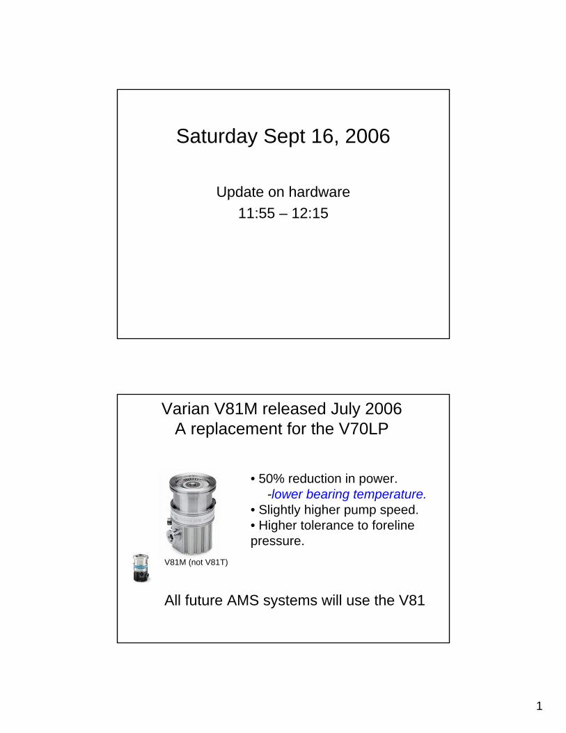
V81M (not V81T)
• 50% reduction in power. -lower bearing temperature.
• Slightly higher pump speed.• Higher tolerance to forelinepressure.
All future AMS systems will use the V81
Varian V81M released July 2006A replacement for the V70LP
2
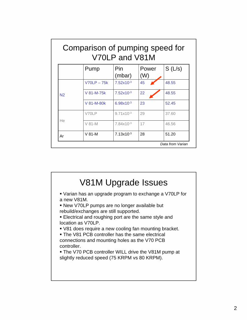
Comparison of pumping speed for V70LP and V81M
51.20287.13x10-3V 81-MAr
46.56177.84x10-3V 81-M
37.60299.71x10-3V70LP
He
52.45236.98x10-3V 81-M-80k
48.55227.52x10-3V 81-M-75k
48.55457.52x10-3V70LP – 75k
N2
S (L/s)Power (W)
Pin (mbar)
Pump
Data from Varian
V81M Upgrade IssuesVarian has an upgrade program to exchange a V70LP for
a new V81M.New V70LP pumps are no longer available but
rebuild/exchanges are still supported.Electrical and roughing port are the same style and
location as V70LP.V81 does require a new cooling fan mounting bracket.The V81 PCB controller has the same electrical
connections and mounting holes as the V70 PCB controller.
The V70 PCB controller WILL drive the V81M pump at slightly reduced speed (75 KRPM vs 80 KRPM).
3
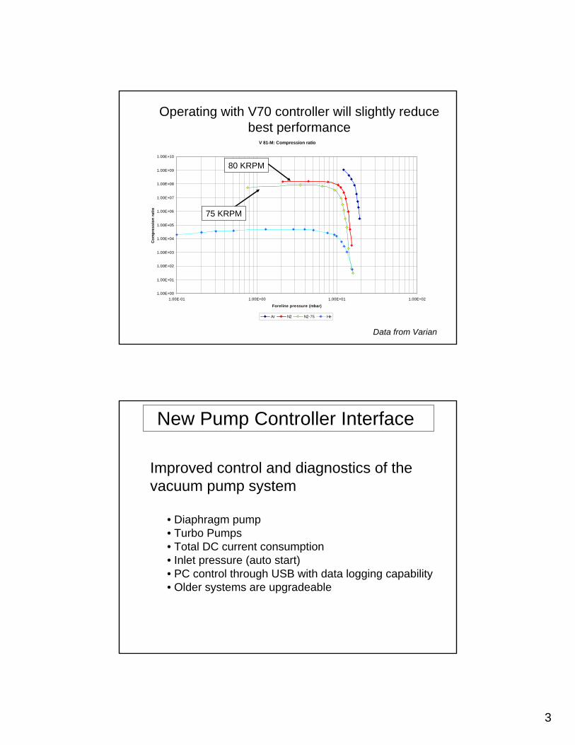
V 81-M: Compression ratio
1.00E+00
1.00E+01
1.00E+02
1.00E+03
1.00E+04
1.00E+05
1.00E+06
1.00E+07
1.00E+08
1.00E+09
1.00E+10
1.00E-01 1.00E+00 1.00E+01 1.00E+02
Foreline pressure (mbar)
Com
pres
sion
ratio
Ar N2 N2-75 He
Operating with V70 controller will slightly reduce best performance
75 KRPM
80 KRPM
Data from Varian
New Pump Controller Interface
Improved control and diagnostics of the vacuum pump system
• Diaphragm pump• Turbo Pumps• Total DC current consumption• Inlet pressure (auto start)• PC control through USB with data logging capability• Older systems are upgradeable
4
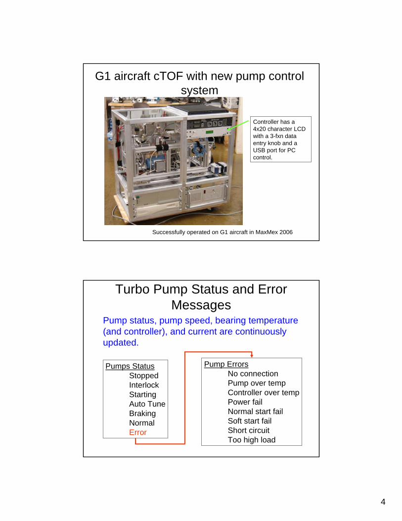
G1 aircraft cTOF with new pump control system
Controller has a 4x20 character LCD with a 3-fxn data entry knob and a USB port for PC control.
Successfully operated on G1 aircraft in MaxMex 2006
Turbo Pump Status and Error Messages
Pump ErrorsNo connectionPump over tempController over tempPower failNormal start failSoft start failShort circuitToo high load
Pumps StatusStoppedInterlockStartingAuto TuneBrakingNormalError
Pump status, pump speed, bearing temperature (and controller), and current are continuously updated.
5
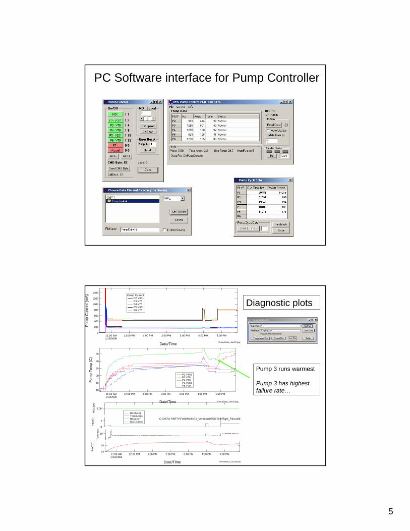
PC Software interface for Pump Controller
20
10Box
T(C
)
11:00 AM1/19/2006
12:00 PM 1:00 PM 2:00 PM 3:00 PM 4:00 PM 5:00 PM
Date/Time
10
TotA
mps
2
0
P(to
rr)
6.00
MD
1Spd
BoxTemp TotalAmps Baratron MD1Speed
PumpStats_Jan19.pxp
35
30
25
20
15
10
Pum
p Te
mp
(C)
11:00 AM1/19/2006
12:00 PM 1:00 PM 2:00 PM 3:00 PM 4:00 PM 5:00 PM
Date/Time
P2 V301 P3 V70 P4 V70 P5 V301 P6 V70
PumpStats_Jan19.pxp
1400
1200
1000
800
600
400
200
0
Pum
p C
urre
nt (m
A)
11:00 AM1/19/2006
12:00 PM 1:00 PM 2:00 PM 3:00 PM 4:00 PM 5:00 PM
Date/Time
Pump Current P2 V301 P3 V70 P4 V70 P5 V301 P6 V70
PumpStats_Jan19.pxp
C:\DATA PARTY\FieldWork\G1_Veracruz06\G1TestFlight_Pasco06
Pump 3 runs warmest
Pump 3 has highest failure rate…
Diagnostic plots
6
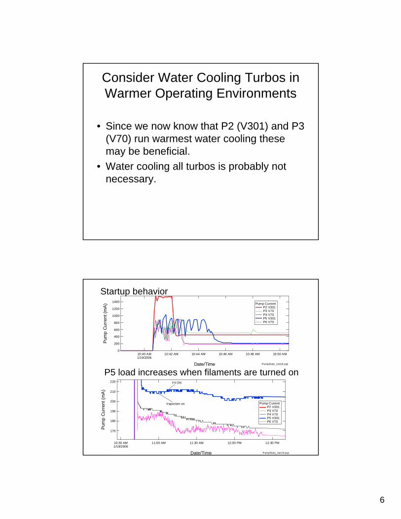
Consider Water Cooling Turbos in Warmer Operating Environments
• Since we now know that P2 (V301) and P3 (V70) run warmest water cooling these may be beneficial.
• Water cooling all turbos is probably not necessary.
1400
1200
1000
800
600
400
200
0
Pum
p C
urre
nt (m
A)
10:40 AM1/19/2006
10:42 AM 10:44 AM 10:46 AM 10:48 AM 10:50 AM
Date/Time
Pump Current P2 V301 P3 V70 P4 V70 P5 V301 P6 V70
PumpStats_Jan19.pxp
220
210
200
190
180
170
Pum
p C
urre
nt (m
A)
10:30 AM1/19/2006
11:00 AM 11:30 AM 12:00 PM 12:30 PM
Date/Time
Pump Current P2 V301 P3 V70 P4 V70 P5 V301 P6 V70
Vaporizer on
Fil ON
PumpStats_Jan19.pxp
Startup behavior
P5 load increases when filaments are turned on
7
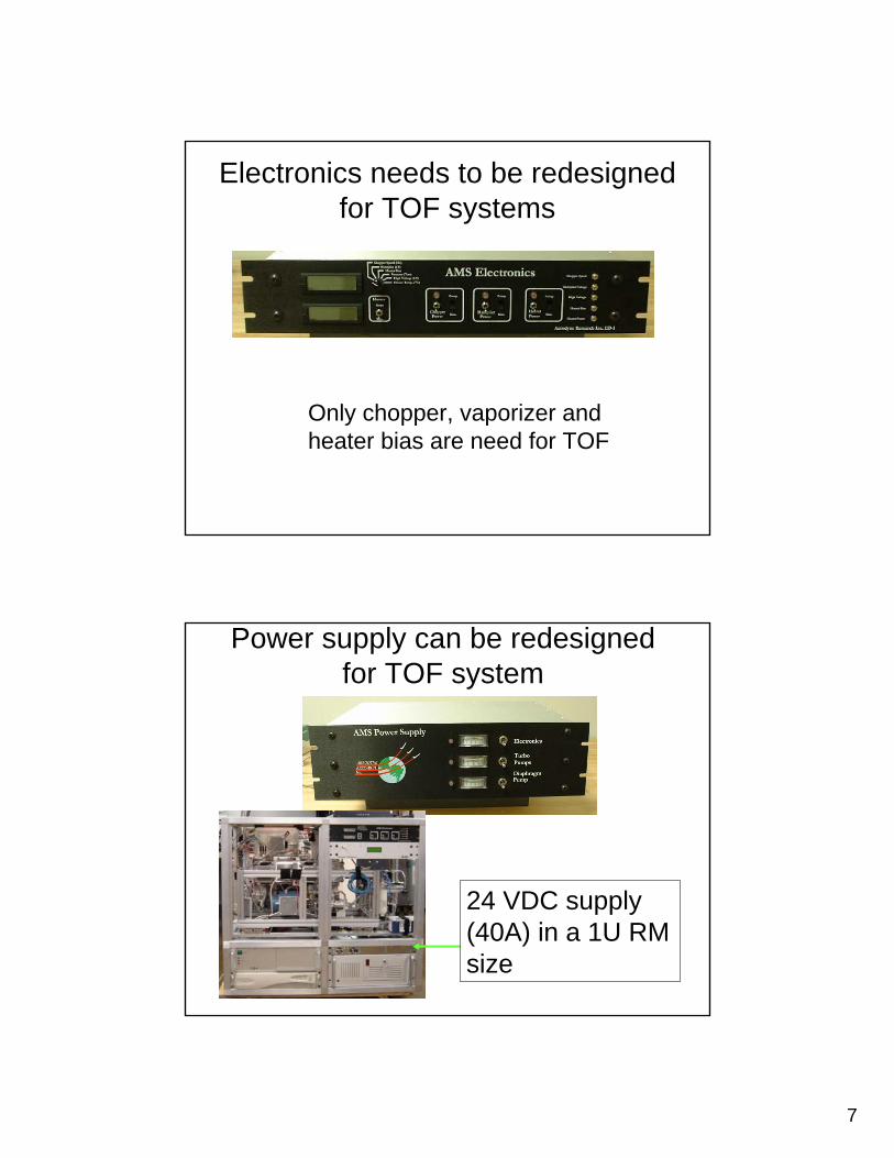
Electronics needs to be redesigned for TOF systems
Only chopper, vaporizer and heater bias are need for TOF
Power supply can be redesigned for TOF system
24 VDC supply (40A) in a 1U RM size
8
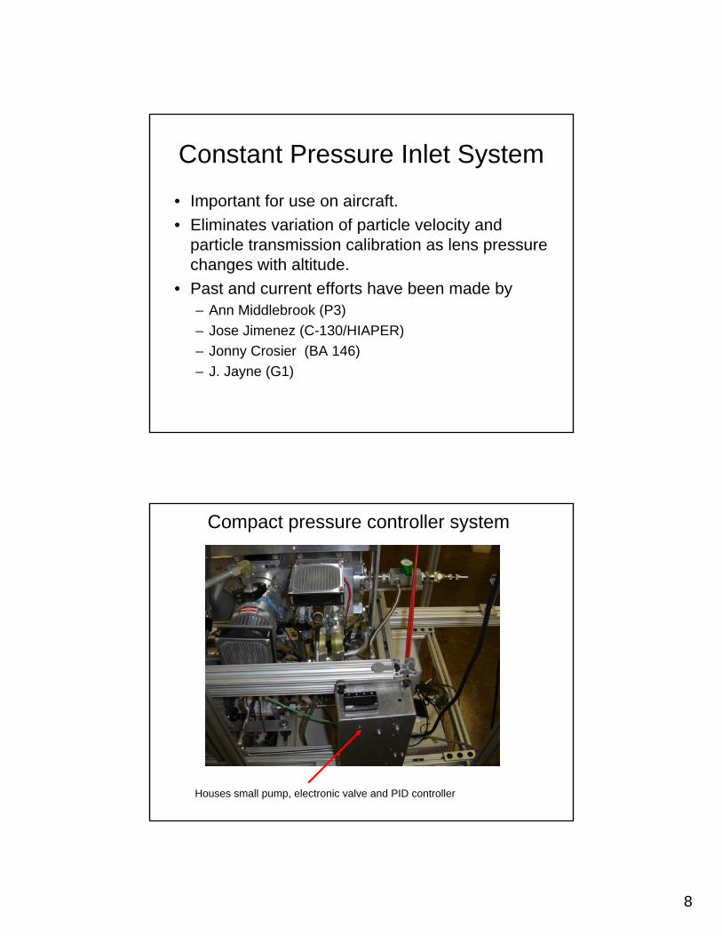
Constant Pressure Inlet System
• Important for use on aircraft. • Eliminates variation of particle velocity and
particle transmission calibration as lens pressure changes with altitude.
• Past and current efforts have been made by – Ann Middlebrook (P3)– Jose Jimenez (C-130/HIAPER)– Jonny Crosier (BA 146)– J. Jayne (G1)
Compact pressure controller system
Houses small pump, electronic valve and PID controller
9
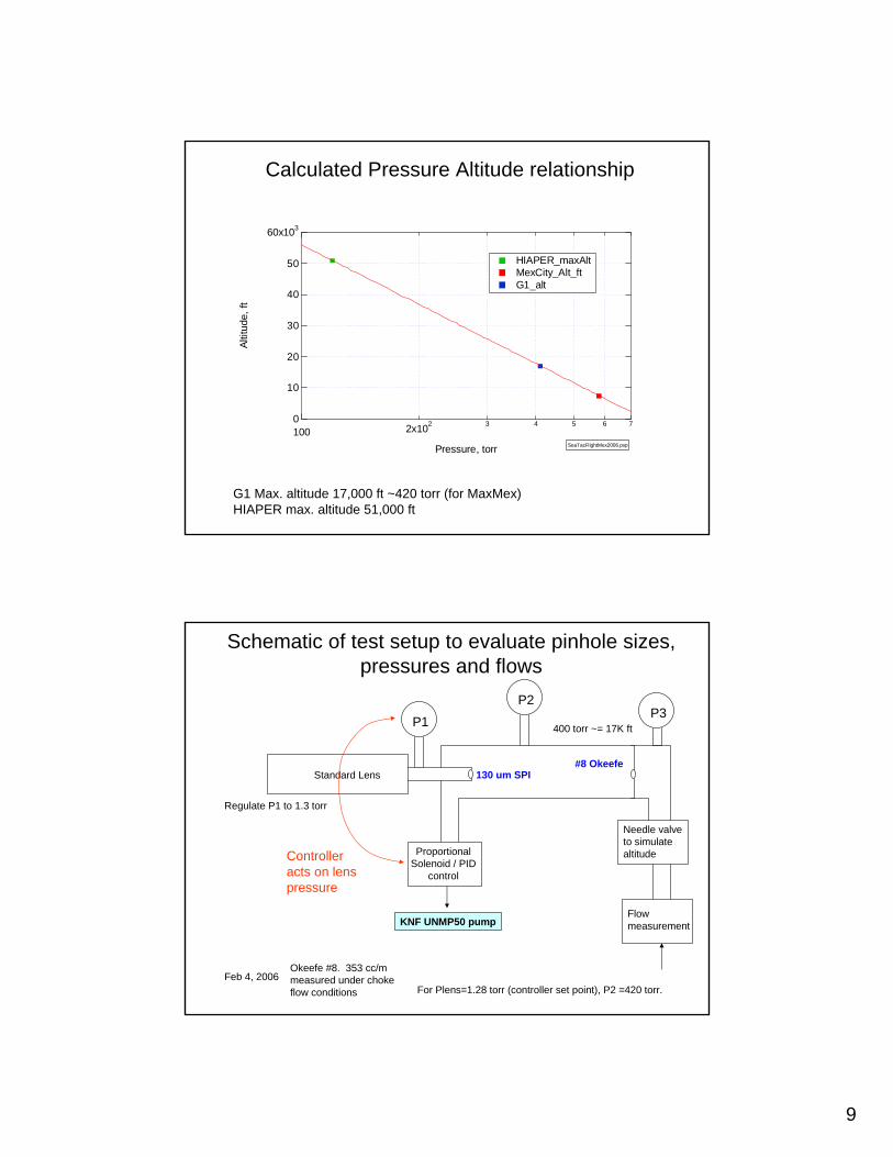
Calculated Pressure Altitude relationship
G1 Max. altitude 17,000 ft ~420 torr (for MaxMex)HIAPER max. altitude 51,000 ft
60x103
50
40
30
20
10
0
Altit
ude,
ft
100 2x10² 3 4 5 6 7
Pressure, torr
HIAPER_maxAlt MexCity_Alt_ft G1_alt
SeaTacFlightMex2006.pxp
P2
Proportional Solenoid / PID
control
P1
Standard Lens
400 torr ~= 17K ft
Regulate P1 to 1.3 torr
Feb 4, 2006
130 um SPI#8 Okeefe
For Plens=1.28 torr (controller set point), P2 =420 torr.
Okeefe #8. 353 cc/m measured under choke flow conditions
Schematic of test setup to evaluate pinhole sizes, pressures and flows
Flow measurement
Needle valve to simulate altitude
P3
KNF UNMP50 pump
Controller acts on lens pressure
10
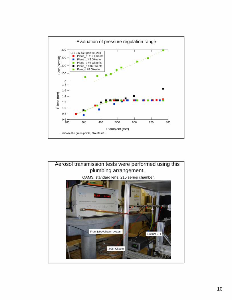
Evaluation of pressure regulation range
I choose the green points, Okeefe #8…
1.8
1.6
1.4
1.2
1.0
0.8
0.6
P le
ns (t
orr)
800700600500400300200
P ambient (torr)
400
300
200
100
0
Flow
(cc/
min
)
130 um, Set point=1.260 Plens_b #10 Okeefe Plens_c #5 Okeefe Plens_d #8 Okeefe. Plens_e #16 Okeefe Flow_d #8 Okeefe
Aerosol transmission tests were performed using this plumbing arrangement.
QAMS, standard lens, 215 series chamber.
From DMA/dilution system
.008” Okeefe
130 um SPI
11
1000
800
600
400
200
0
AMS
(#/c
c)
10008006004002000
CPC (#/cc)
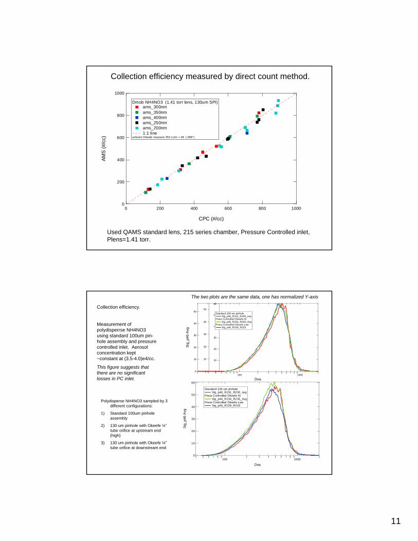
Dmob NH4NO3 (1.41 torr lens, 130um SPI) ams_300nm ams_350nm ams_400nm ams_250nm ams_200nm 1:1 line
unkown Okeefe measure 353 cc/m = #8 (.008")
Collection efficiency measured by direct count method.
Used QAMS standard lens, 215 series chamber, Pressure Controlled inlet, Plens=1.41 torr.
60
50
40
30
20
10
0
Sig_
p46
Avg
4 5 6 7 8 9100
2 3 4 5 6 7 8 91000
2
Dva
Standard 100 um pinhole Sig_p46_R231_R230_avg
Press Controlled Okeefe Hi Sig_p46_R234_R235_Avg
Press Controlled Okeefe Low Sig_p46_R228_R233
50
40
30
20
10
0
Sig_
p46
Avg
2 3 4 5 6 7 8 9100
2 3 4 5 6 7 8 91000
2
Dva
50
40
30
20
10
0
60
50
40
30
20
10
0
Standard 100 um pinhole Sig_p46_R231_R230_avg
Press Controlled Okeefe Hi Sig_p46_R234_R235_Avg
Press Controlled Okeefe Low Sig_p46_R228_R233
Polydisperse NH4NO3 sampled by 3 different configurations:
1) Standard 100um pinhole assembly
2) 130 um pinhole with Okeefe ¼” tube orifice at upstream end (high)
3) 130 um pinhole with Okeefe ¼” tube orifice at downstream end
The two plots are the same data, one has normalized Y-axis
Collection efficiency.
Measurement of polydisperrse NH4NO3 using standard 100um pin-hole assembly and pressure controlled inlet. Aerosol concentration kept ~constant at (3.5-4.0)e4/cc.
This figure suggests that there are no significant losses in PC inlet.
12
Pressure Controller Summary• Determine lowest pressure range for
operation…select pinholes and pump.• Use the lens pressure as the pressure to
regulate. – Eliminates a second pressure gauge
• For sampling pressures >~400 torr losses seem to be small.
• For sampling pressures <~400 torr losses may be significant. Need to design better sampling interface to minimize losses.
• Application: tunable pressure lens
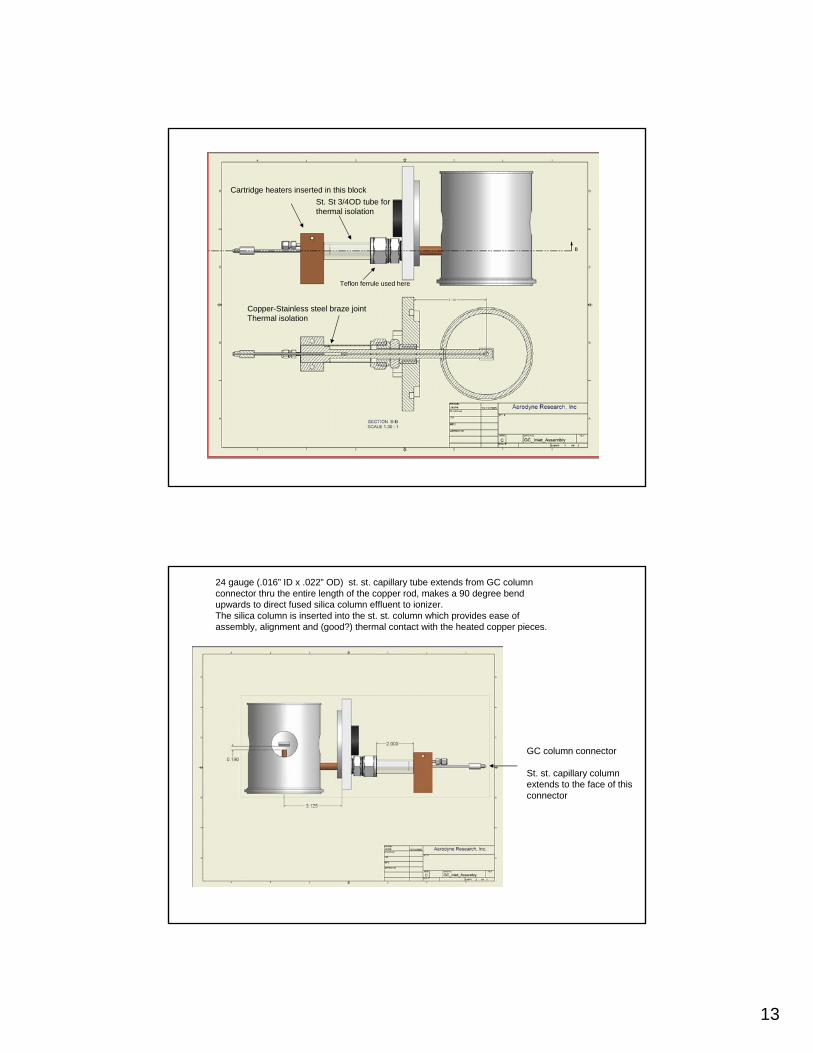
Direct Probe GC Inlet
• Designed for Dr. Akiama at Japanese Automobile Research Institute (JARI)
• Allows use of TOF spectrometer to measure effulents from GC capilarycolumn
13
Copper-Stainless steel braze jointThermal isolation
Cartridge heaters inserted in this blockSt. St 3/4OD tube for thermal isolation
Teflon ferrule used here
24 gauge (.016” ID x .022” OD) st. st. capillary tube extends from GC column connector thru the entire length of the copper rod, makes a 90 degree bend upwards to direct fused silica column effluent to ionizer.The silica column is inserted into the st. st. column which provides ease of assembly, alignment and (good?) thermal contact with the heated copper pieces.
GC column connector
St. st. capillary column extends to the face of this connector
14
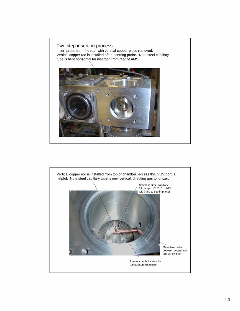
Two step insertion process.Insert probe from the rear with vertical copper piece removed.Vertical copper rod is installed after inserting probe. Note steel capillary tube is bent horizontal for insertion from rear of AMS.
Vertical copper rod is installed from top of chamber, access thru VUV port is helpful. Note steel capillary tube is now vertical, directing gas to ionizer.
Thermocouple location for temperature regulation
Stainless Steel capillary24 gauge. .016” ID x .022 OD (hard to see in photo)
Make No contact between copper rod and Al. cylinder…
15
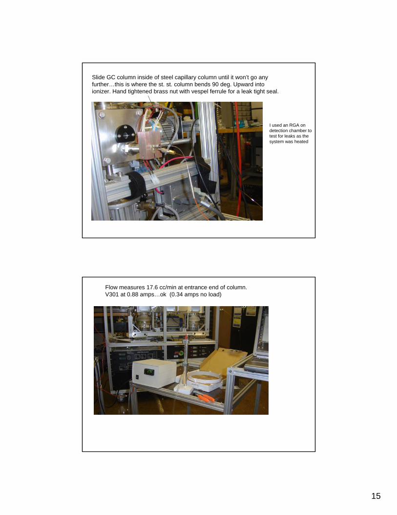
Slide GC column inside of steel capillary column until it won’t go any further…this is where the st. st. column bends 90 deg. Upward into ionizer. Hand tightened brass nut with vespel ferrule for a leak tight seal.
I used an RGA on detection chamber to test for leaks as the system was heated
Flow measures 17.6 cc/min at entrance end of column.V301 at 0.88 amps…ok (0.34 amps no load)
16
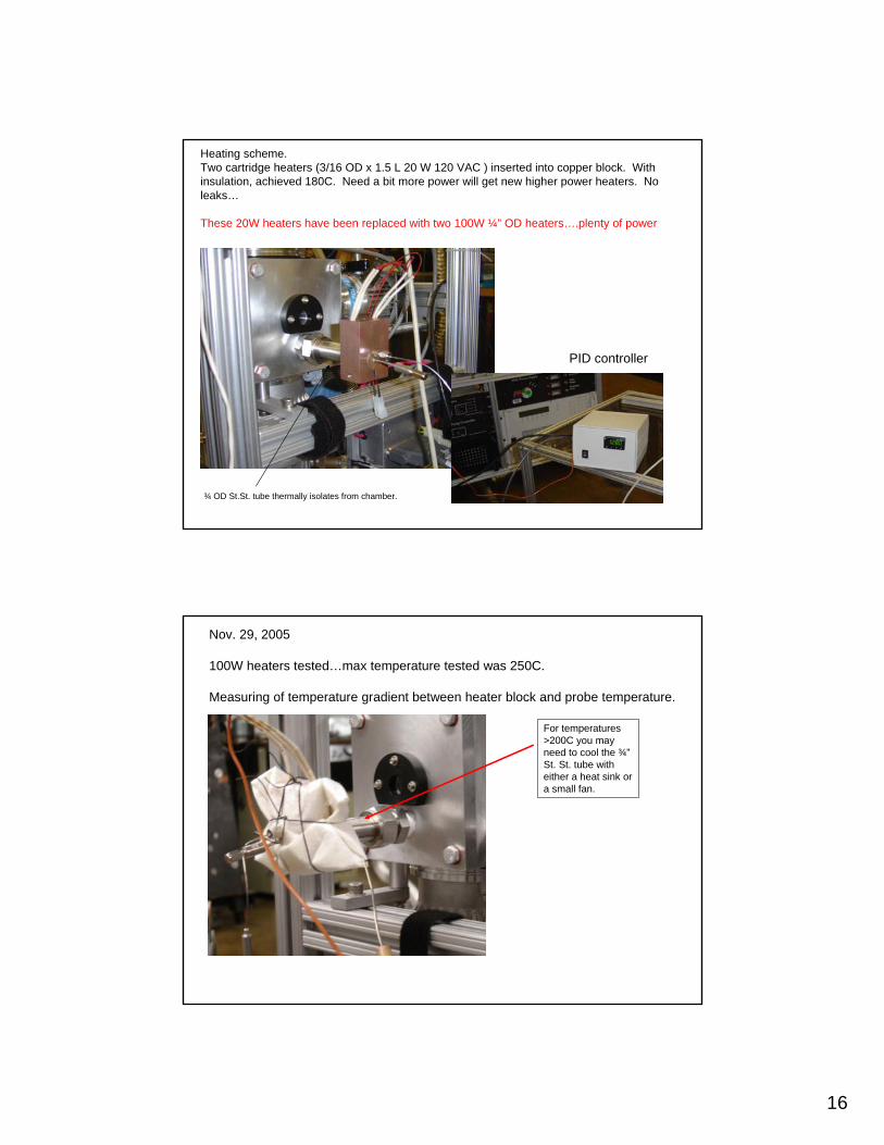
Heating scheme. Two cartridge heaters (3/16 OD x 1.5 L 20 W 120 VAC ) inserted into copper block. With insulation, achieved 180C. Need a bit more power will get new higher power heaters. No leaks…
These 20W heaters have been replaced with two 100W ¼” OD heaters….plenty of power
¾ OD St.St. tube thermally isolates from chamber.
PID controller
Nov. 29, 2005
100W heaters tested…max temperature tested was 250C.
Measuring of temperature gradient between heater block and probe temperature.
For temperatures >200C you may need to cool the ¾” St. St. tube with either a heat sink or a small fan.
17
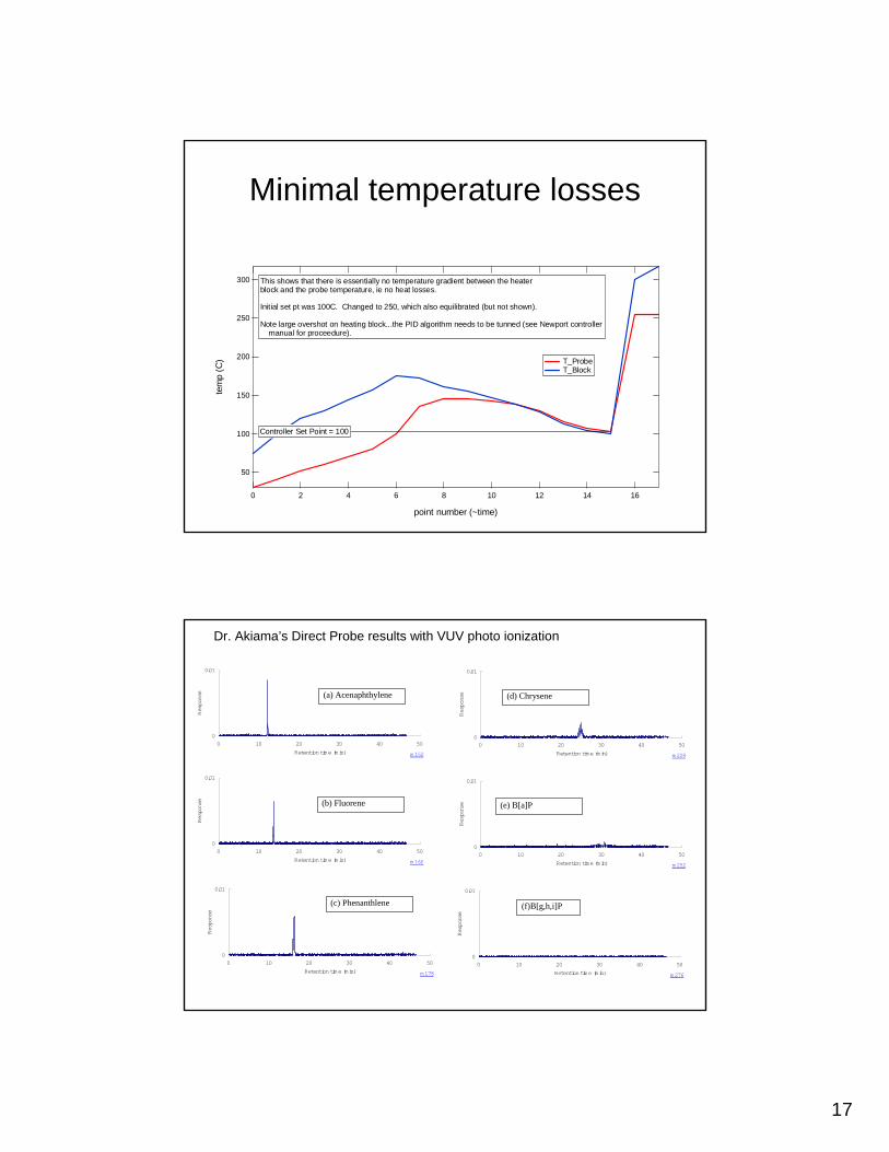
Minimal temperature losses
300
250
200
150
100
50
tem
p (C
)
1614121086420
point number (~time)
T_Probe T_Block
Controller Set Point = 100
This shows that there is essentially no temperature gradient between the heater block and the probe temperature, ie no heat losses. Initial set pt was 100C. Changed to 250, which also equilibrated (but not shown). Note large overshot on heating block...the PID algorithm needs to be tunned (see Newport controller manual for proceedure).
0
0.01
0 10 20 30 40 50Retention time (min)
Response
m 152
0
0.01
0 10 20 30 40 50Retention time (min)
Response
m 166
0
0.01
0 10 20 30 40 50Retention time (min)
Response
m178
0
0.01
0 10 20 30 40 50Retention time (min)
Response
m228
0
0.01
0 10 20 30 40 50Retention time (min)
Response
m252
0
0.01
0 10 20 30 40 50Retention time (min)
Response
m276
(a) Acenaphthylene
(b) Fluorene
(c) Phenanthlene
(d) Chrysene
(e) B[a]P
(f)B[g,h,i]P
Dr. Akiama’s Direct Probe results with VUV photo ionization


![WELCOME [] · Saturday Sept. 9 5:00 pm LaRoux Children by Harold & Mary LaRoux Sunday Sept. 10 9:00 am Rodney Auck (RIP) by Jimmy & Sandy Nichols Saturday Sept. 16 5:00 pm James Mack](https://img.pdfslide.net/doc/110x75/5fc0fae1de50622f15134baf/welcome-saturday-sept-9-500-pm-laroux-children-by-harold-mary-laroux.jpg)

![Udaipur Engineers : [startup saturday] 13 Sept 14](https://img.pdfslide.net/doc/110x75/568c57531a28ab4916ca1568/udaipur-engineers-startup-saturday-13-sept-14.jpg)