Embed Size (px)
Citation preview
SAVI: an actively controlled teleconferencing system
R. Herpersa,b,*, K. Derpanisa, W.J. MacLeanc, G. Verghesed, M. Jenkina, E. Miliosa, A. Jepsond,J.K. Tsotsosa
aYork Centre for Vision Research, Department of Computer Science, York University, 4700 Keele Street, Toronto, Ontario, Canada, M3J 1P3bDepartment of Applied Computer Science, University of Applied Sciences, Fachhochschule Bonn-Rhein-Sieg, Grantham Allee 20,
53757 Sankt Augustin, GermanycDepartment of Electrical and Computer Engineering, University of Toronto, 6 King's College Road, Toronto, Ontario, Canada, M5S 3G4
dDepartment of Computer Science, University of Toronto, 10 King's College Road, Toronto, Ontario, Canada, M5S 3G4
Accepted 10 December 2000
Abstract
A Stereo Active Vision Interface (SAVI) is introduced which detects frontal faces in real world environments and performs particular
active control tasks dependent on hand gestures given by the person the system attends to. The SAVI system is thought of as a smart user
interface for teleconferencing, telemedicine, and distance learning applications.
To reduce the search space in the visual scene the processing is started with the detection of connected skin colour regions applying a new
radial scanline algorithm. Subsequently, in the most salient skin colour region facial features are searched for while the skin colour blob is
actively kept in the centre of the visual ®eld of the camera system. After a successful evaluation of the facial features the associated person is
able to give control commands to the system. For this contribution only visual control commands are investigated but there is no limitation
for voice or any other commands. These control commands can either effect the observing system itself or any other active or robotic system
wired to the principle observing system via TCP/IP sockets.
The system is designed as a perception-action-cycle (PAC), processing sensory data of different kinds and qualities. Both the vision
module and the head motion control module work at frame rate on a PC platform. Hence, the system is able to react instantaneously to
changing conditions in the visual scene. q 2001 Elsevier Science B.V. All rights reserved.
Keywords: Active vision interface; Teleconferencing system; Face and hand gesture recognition; Computer Vision System
1. Introduction
Most current vision systems just record, compress and
transmit video signals with video being captured from static
cameras with a wide angle view. They mostly don't include
any sophisticated features to react appropriately to changing
conditions, e.g. the observed person has moved a bit or is
pointing to a particular object or location of interest.
Furthermore, based on their need to use wide angle optics
no sophisticated but important features are available such as
zoom in or track on an object of interest. For that reason
static vision systems have to be replaced by more active
vision systems, in which sensory data are processed in a
closed loop and basic information about the observed
scene can be analyzed. The derived information is then
reused to guide and/or control the system.
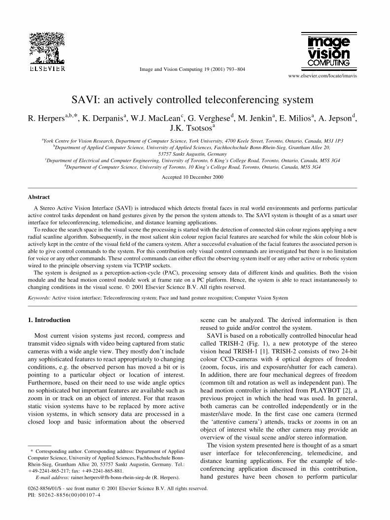
SAVI is based on a robotically controlled binocular head
called TRISH-2 (Fig. 1), a new prototype of the stereo
vision head TRISH-1 [1]. TRISH-2 consists of two 24-bit
colour CCD-cameras with 4 optical degrees of freedom
(zoom, focus, iris and exposure/shutter for each camera).
In addition, there are four mechanical degrees of freedom
(common tilt and rotation as well as independent pan). The
head motion controller is inherited from PLAYBOT [2], a
previous project in which the head was used. In general,
both cameras can be controlled independently or in the
master/slave mode. In the ®rst case one camera (termed
the `attentive camera') attends, tracks or zooms in on an
object of interest while the other camera may provide an
overview of the visual scene and/or stereo information.
The vision system presented here is thought of as a smart
user interface for teleconferencing, telemedicine, and
distance learning applications. For the example of tele-
conferencing application discussed in this contribution,
hand gestures have been chosen to perform particular
Image and Vision Computing 19 (2001) 793±804
0262-8856/01/$ - see front matter q 2001 Elsevier Science B.V. All rights reserved.
PII: S0262-8856(00)00107-4
www.elsevier.com/locate/imavis
* Corresponding author. Corresponding address: Department of Applied
Computer Science, University of Applied Sciences, Fachhochschule Bonn-
Rhein-Sieg, Grantham Allee 20, 53757 Sankt Augustin, Germany. Tel.:
149-2241-865-217; fax: 149-2241-865-881.
E-mail address: rainer.herpers@fh-bonn-rhein-sieg-de (R. Herpers).
control tasks. The hand gesture commands are used to
control either the observing system itself or another active
vision system connected to the principle one (see Fig. 2).
The control commands are thought of as an obvious way to
interact with a mostly autonomous or self-guided system.
Based on our system design the active vision system is
performing closed control loops in real time on visual data
only.
The presented work is mostly related to the work done in
the area of intelligent environments [3,4], multimodal user
interfaces, and advanced multi-media systems [5,6]. Most of
these systems do not include any active control. They are
based on a ®xed camera setup with a wide angle view and do
not provide any possibility of changing their internal
settings with respect to the above mentioned degrees of
freedom. Kjeldsen and Kender [7] devised a technique for
doing skin-tone segmentation in HSV space, based on the
premise that skin tone in images occupies a connected
volume in HSV space. They further developed a system
which used a back-propagation neural network to recognize
gestures from the segmented hand images [8,9]. Freeman
and Weissman [10] use hand movements to adjust `control
bars' by detecting rising hand movements (as a trigger to
start the system) and then relative hand movements to
manipulate the controls. Freeman et al. [11] also report on
the development of a system where hand gestures are substi-
tuted for mouse interaction. The hand is imaged against an
uncluttered background, and the hand's movements in 2-D
are interpreted the same as mouse movements. The system
is demonstrated using a ¯ight-simulator game, where hand
movements control the joystick. Utsumi and Ohta [12] used
a 5-camera setup to view a hand against a uniform back-
ground, and segment it using Sobel edge detection. Their
system was capable of recognising seven different gestures
(based on the number of ®ngers being held up). Hamdam et
al. [13] studied the dynamics of hand gestures, and used
hidden Markov models (HMMs) to model the transitions
between gestures. Recognition involves eigenimages
derived from a training set, but the system is sensitive to
the scale and orientation of the hand, and like previous
approaches requires an uncluttered background. Finally,
Jennings [14] demonstrates robust gesture detection results
against cluttered backgrounds in a system which uses four
cameras (three grey-scale, one colour). However, the
method is very compute-intensive.
In the next section the different logical units of the system
and their interrelationship will be introduced brie¯y. Subse-
quently, several modules will be presented completely.
Some details concerning hardware speci®cations and
conclusions are given at the end of the contribution.
2. SAVI system description
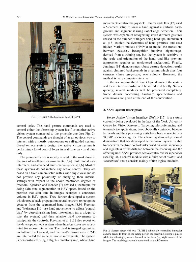
Stereo Active Vision Interface (SAVI) [15] is a system
currently being developed in the labs of the York University
Centre for Vision Research. Targeting teleconferencing and
telemedicine applications, two robotically controlled binocu-
lar heads and their processing units have been connected via
TCP/IP sockets (Fig. 2). The chosen system setup should
demonstrate that our developed active vision system is able
to cope with real time control tasks based on visual input only
and regardless of the distance between the receiving and the
affecting unit. SAVI provides active control via its supervisor
(see Fig. 3), a control module with a ®nite set of `states' and
`transitions' and it consists mainly of ®ve logical modules:
R. Herpers et al. / Image and Vision Computing 19 (2001) 793±804794
Fig. 1. TRISH-2, the binocular head of SAVI.
Fig. 2. System setup with two TRISH-2 robotically controlled binocular
camera heads. In front of the acting person the receiving system is placed
while the affecting system is located in the back (top right corner of the
image). The receiving system is monitored on the PC-screen.
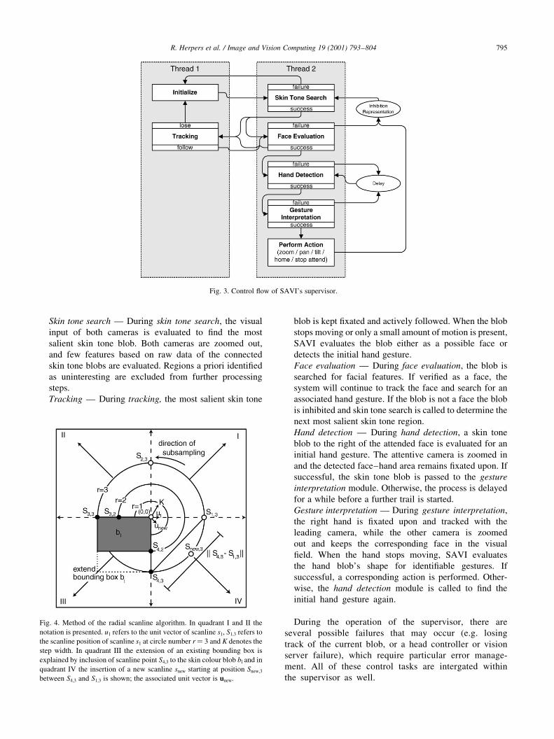
Skin tone search Ð During skin tone search, the visual
input of both cameras is evaluated to ®nd the most
salient skin tone blob. Both cameras are zoomed out,
and few features based on raw data of the connected
skin tone blobs are evaluated. Regions a priori identi®ed
as uninteresting are excluded from further processing
steps.
Tracking Ð During tracking, the most salient skin tone
blob is kept ®xated and actively followed. When the blob
stops moving or only a small amount of motion is present,
SAVI evaluates the blob either as a possible face or
detects the initial hand gesture.
Face evaluation Ð During face evaluation, the blob is
searched for facial features. If veri®ed as a face, the
system will continue to track the face and search for an
associated hand gesture. If the blob is not a face the blob
is inhibited and skin tone search is called to determine the
next most salient skin tone region.
Hand detection Ð During hand detection, a skin tone
blob to the right of the attended face is evaluated for an
initial hand gesture. The attentive camera is zoomed in
and the detected face±hand area remains ®xated upon. If
successful, the skin tone blob is passed to the gesture
interpretation module. Otherwise, the process is delayed
for a while before a further trail is started.
Gesture interpretation Ð During gesture interpretation,
the right hand is ®xated upon and tracked with the
leading camera, while the other camera is zoomed
out and keeps the corresponding face in the visual
®eld. When the hand stops moving, SAVI evaluates
the hand blob's shape for identi®able gestures. If
successful, a corresponding action is performed. Other-
wise, the hand detection module is called to ®nd the
initial hand gesture again.
During the operation of the supervisor, there are
several possible failures that may occur (e.g. losing
track of the current blob, or a head controller or vision
server failure), which require particular error manage-
ment. All of these control tasks are intergated within
the supervisor as well.
R. Herpers et al. / Image and Vision Computing 19 (2001) 793±804 795
Fig. 3. Control ¯ow of SAVI's supervisor.
Fig. 4. Method of the radial scanline algorithm. In quadrant I and II the
notation is presented. u1 refers to the unit vector of scanline s1, S1,3 refers to
the scanline position of scanline s1 at circle number r� 3 and K denotes the
step width. In quadrant III the extension of an existing bounding box is
explained by inclusion of scanline point S4,3 to the skin colour blob bl and in
quadrant IV the insertion of a new scanline snew starting at position Snew,3
between S4,3 and S1,3 is shown; the associated unit vector is unew.
3. Skin tone search
For ef®cient real-time skin colour blob detection, a radial
scanline detection method has been developed. Starting at
the center of a particular rectangular image region (region of
interest, ROI), it scans radially outward along approxi-
mately concentric circles with a particular step width K
(Figs. 4 and 5). A scanline s is de®ned by its unit vector uand the circle number r, which is multiplied by the constant
factor K mentioned previously. The unit vector u is de®ned
by its origin O� (0,0) and a point Punit� (x,y) on the unit
circle, with iui� 1. For simplicity the unit vector is de®ned
only by its point on the unit circle u:� (x,y) assuming that
the origin O is ®xed. The inital set of scanlines is given by
an ordered set (counter clockwise) of unit vectors
U:� {u1,¼,uh} with h:� 2a, a $ 2. The head position
Sui ;r�x; y� or for simplicity Si,r(x,y) of a particular scanline
si is calculated by:
Si;r�x; y� � ui�x; y� £ r £ K
Fig. 4 shows the main principles of the scanline
algorithm. Fundamental to the radial scanline algorithm is
the construction and continuous update of a number of
bounding box representations, bj, which cover the under-
lying connected skin tone regions. For the computations
of the bounding box representations, some additional
functions are necessary:
² A boolean function:
skin�x� :�1; if colour�x� � skin tone
0; otherwise
(
² A neighbourhood function N�si� :��Si;r21; Si21;r
for
i . 1. For i� 1 the neighbourhood N is reduced to N�s1� :� �
S1;r21
: Only at the beginning of the scan, the bound-
ing box representations bj are initialized so that in this
case no neighbourhood exists.
² A blob association function bl(x):� bj with bj blob
number of the blob list B, B :� {null; b1;¼bm};,
m [ N. A skin tone blob is de®ned as b:� (TL, BR,V ),
where TL:� (x,y) refers to the top left corner, BR:� (x,y)
refers to the bottom right corner of the associated bound-
ing box, and V is a set of scanline positions associated
with that blob, V j:� {Si,j; Si,j are associated to bj}. For
the blob association of a scanline position St,r with t [Indexset of U several cases have to be considered:
where bnew denotes a new blob representation to be
included in B and sk�X� :� P jX jskin�xi�jji�1 where X is a
set of positions X:� {x1,¼,xn}. To ensure that the neigh-
bourhood relationship between the ®rst S1,r and the last
Sh,r scanline heads with respect to a particular circle r is
also considered, these two scanlines are checked if they
are both skin colour after each complete scanning itera-
tion. If so and they do not point to the same blob bl, the
merge function M(b1,bh) is called. Therefore, to be
precise, the just mentioned blob association function
has to be expanded by the following special case:
M�b1; bh�; if skin�S1;r� � skin�Sh;r� � 1 ^ bl�S1;r� ±bl�Sh;r�:In quadrant III of Fig. 4 the extension of an existing
bounding box according to this scheme is explained by
a sample scanline point S4,3 to be included in the skin
colour blob bl.
² A merge function M�bi; bj� � M��TLi;BRi;V i�;�TLj;BRj;V j�� :� bnew if bi and bj
are adjacent, that
means they share at least one direct neighbour in terms
of the neighbourhood de®nition of N.
M�bi; bj� �
TLnew�x� �TLi�x�; if TLi�x� # TLj�x�TLj�x�; otherwise
(
TLnew�y� �TLi�y�; if TLi�y� $ TLj�y�TLj�y�; otherwise
(
BRnew�x� �BRi�x�; if BRi�x� $ BRj�x�BRj�x�; otherwise
(
BRnew�y� �BRi�y�; if BRi�y� # BRj�y�BRj�y�; otherwise
(Vnew � Vi < V j
8>>>>>>>>>>>>>>>>>>><>>>>>>>>>>>>>>>>>>>:bj has to be removed from B while bi will be replaced by
the new merged blob bnew.
If the distance between the heads of two successive scan-
lines exceeds a prede®ned threshold��Si;rf
2 Si11;rf
�� . D�����
then a new scanline is spawned and inserted between
them with intermediate orientation (Fig. 4, quadrant IV).
The new scanline snew is de®ned only for circle numbers
r $ rf. The ®rst head position is calculated using the
R. Herpers et al. / Image and Vision Computing 19 (2001) 793±804796
bl�St;r� �
bnew; if skin�St;r� � 1 ^ sk�N�St;r�� � 0;
bl�N�St;r��; if skin�St;r� � 1 ^ sk�N�St;r�� � 1_�sk�N�St;r�� � 2 ^ bl�St;r21� � bl�St21;r��;
M�bi; bj�; if skin�St;r� � 1 ^ sk�N�St;r�� � 2 ^ bl�St;r21� ± bl�St21;r�;null; otherwise:
8>>>>>>><>>>>>>>:
following equation:
Snew;rf� Si;rf
1 Si11;rf
2
while the corresponding unit vector unew is given by:
unew �Snew;rf
Snew;rf
The new unit vector unew must be inserted into U, hence,
the elements of U must be reindexed appropriately to main-
tain the ordered set. In quadrant IV of Fig. 4, the insertion of
a new scanline snew starting at position Snew,3 is shown.
The processing of the scan line algorithm presented
ensures that the entire area of interest is considered, by
starting with a high density in the center and reducing
slightly the scan-density in the periphery (Fig. 5). Subse-
quently, the most salient skin colour blob satisfying par-
ticular constraints, e.g. with respect to the size and
position, is processed further.
4. Tracking
Based on a modi®ed version of the radial scan algorithm,
an ef®cient tracking method has been developed. The
dynamic change in position(s) of the bounding box(es)
surrounding the skin tone blob in each frame of the video
sequence is considered and motion vectors with respect to
the centroid(s) of the bounding box(es) are calculated. A
history of past centroid positions is maintained for each
bounding box. Error management ensures that possible
misleading positions are excluded. Only a ®xed fraction of
centroid positions ®tting a special homogeneity criterion are
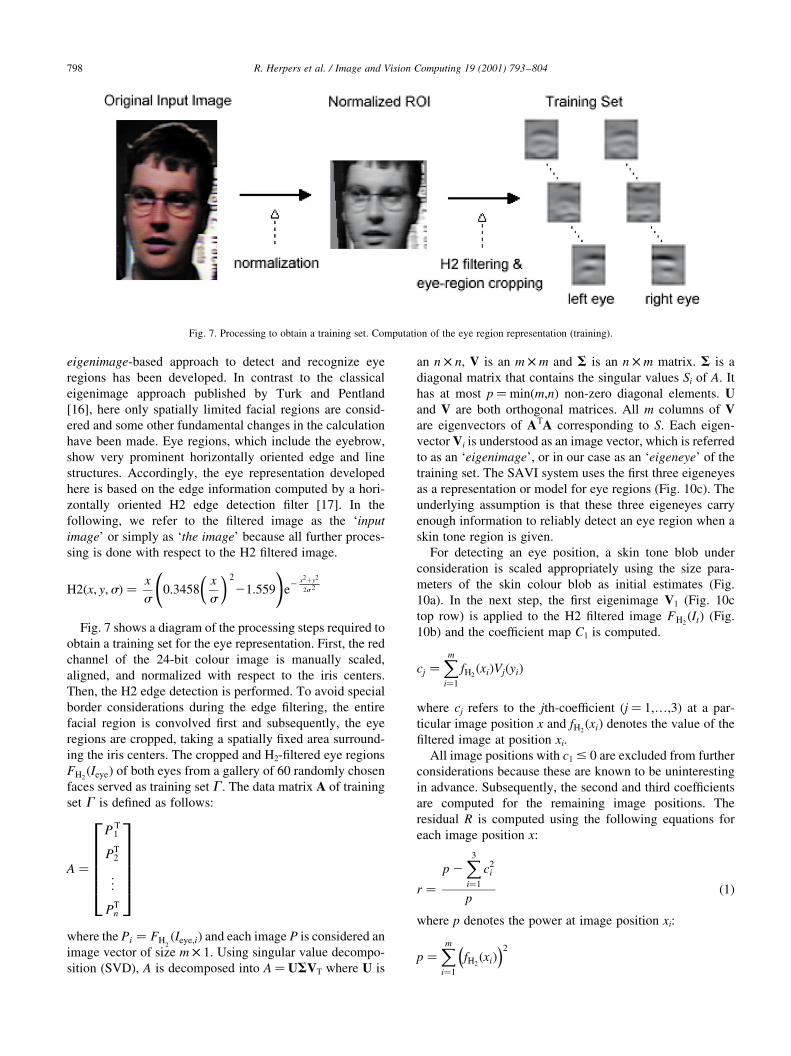
kept. A streak of bright plus signs (approximately 30 tail
positions of the centroid) in Fig. 6 indicates the past posi-
tions of the bounding box centroids, which are stored and/or
updated in the location history. During tracking, the size of
the bounding box of the attended skin colour object is dyna-
mically adjusted by continuously applying a simpli®ed
version of the radial scan algorithm. Furthermore, another
error management process ensures that image collisions that
occur, while the supervisor is attending multiple moving
objects, can also be handled.
To predict the position of the blob's centroid with respect
to a particular future time step, a ®nite set of past motion
steps is evaluated. The green square in Fig. 6 indicates the
predicted centroid position in the next time step. The
computation of a time dependent prediction is particularly
important in maintaining the tracking of a skin tone blob
because tracking cannot be performed continuously without
any break. Breaks may occur if processing power is used for
other tasks or if multiple targets are tracked simultaneously.
It is clear that con®dence will drop rapidly with increasing
time delays, but based on a history of past locations for a
number of frames of the sequence, such a prediction may be
useful for a small time range.
5. Face evaluation
After the skin colour blob detection, a veri®cation of the
most salient skin colour blob is performed. Typical facial
features must be detected in the bounding box area to
ensure that a face is present. The most characteristic and
distinctive facial features are the eye regions. Therefore, an
R. Herpers et al. / Image and Vision Computing 19 (2001) 793±804 797
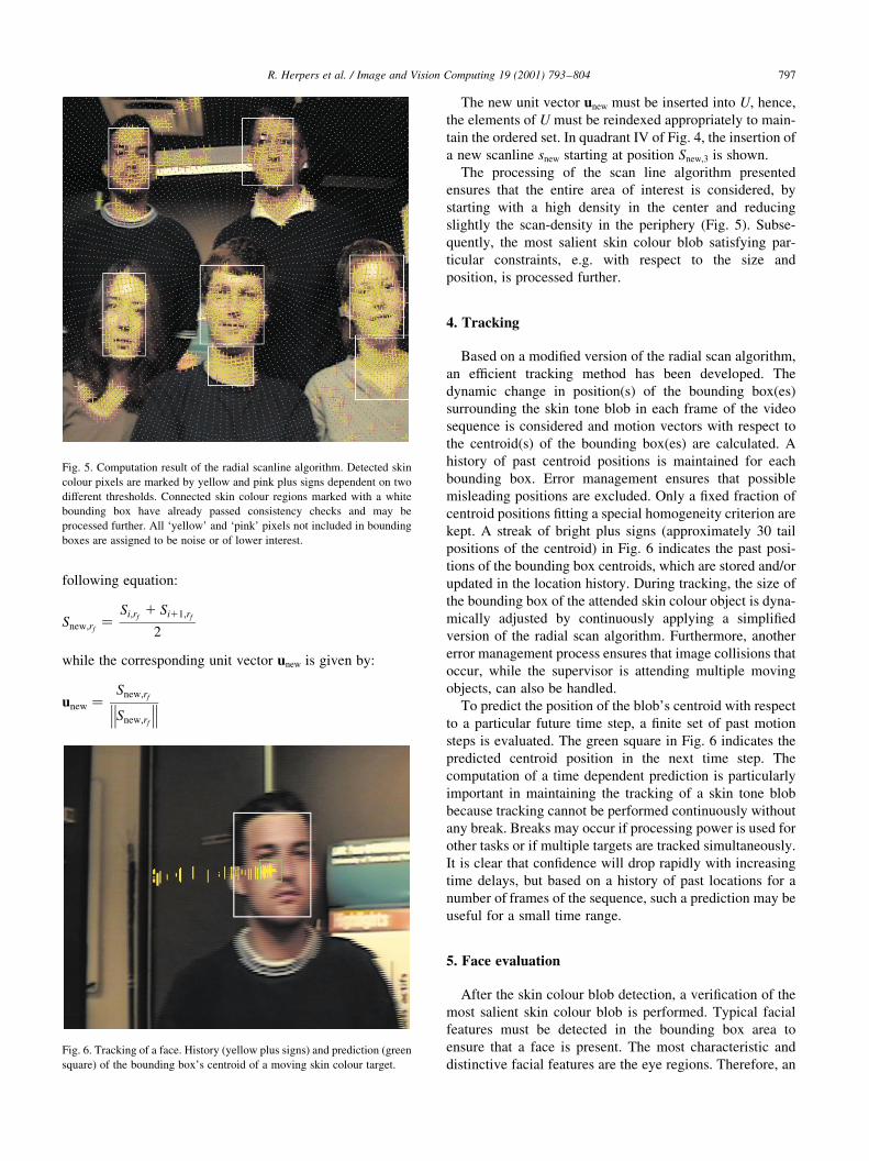
Fig. 5. Computation result of the radial scanline algorithm. Detected skin
colour pixels are marked by yellow and pink plus signs dependent on two
different thresholds. Connected skin colour regions marked with a white
bounding box have already passed consistency checks and may be
processed further. All `yellow' and `pink' pixels not included in bounding
boxes are assigned to be noise or of lower interest.
Fig. 6. Tracking of a face. History (yellow plus signs) and prediction (green
square) of the bounding box's centroid of a moving skin colour target.
eigenimage-based approach to detect and recognize eye
regions has been developed. In contrast to the classical
eigenimage approach published by Turk and Pentland
[16], here only spatially limited facial regions are consid-
ered and some other fundamental changes in the calculation
have been made. Eye regions, which include the eyebrow,
show very prominent horizontally oriented edge and line
structures. Accordingly, the eye representation developed
here is based on the edge information computed by a hori-
zontally oriented H2 edge detection ®lter [17]. In the
following, we refer to the ®ltered image as the `input
image' or simply as `the image' because all further proces-
sing is done with respect to the H2 ®ltered image.
H2�x; y;s� � x
s0:3458
x
s
� � 2
21:559
!e
2 x21y2
2s 2
Fig. 7 shows a diagram of the processing steps required to
obtain a training set for the eye representation. First, the red
channel of the 24-bit colour image is manually scaled,
aligned, and normalized with respect to the iris centers.
Then, the H2 edge detection is performed. To avoid special
border considerations during the edge ®ltering, the entire
facial region is convolved ®rst and subsequently, the eye
regions are cropped, taking a spatially ®xed area surround-
ing the iris centers. The cropped and H2-®ltered eye regions
FH2�Ieye� of both eyes from a gallery of 60 randomly chosen
faces served as training set G . The data matrix A of training
set G is de®ned as follows:
A �
P T1
PT2
..
.
PTn
266666664
377777775where the Pi � FH
2�Ieye;i� and each image P is considered an
image vector of size m £ 1. Using singular value decompo-
sition (SVD), A is decomposed into A� USVT where U is
an n £ n, V is an m £ m and S is an n £ m matrix. S is a
diagonal matrix that contains the singular values Si of A. It
has at most p�min(m,n) non-zero diagonal elements. Uand V are both orthogonal matrices. All m columns of Vare eigenvectors of ATA corresponding to S. Each eigen-
vector Vi is understood as an image vector, which is referred
to as an `eigenimage', or in our case as an `eigeneye' of the
training set. The SAVI system uses the ®rst three eigeneyes
as a representation or model for eye regions (Fig. 10c). The
underlying assumption is that these three eigeneyes carry
enough information to reliably detect an eye region when a
skin tone region is given.
For detecting an eye position, a skin tone blob under
consideration is scaled appropriately using the size para-
meters of the skin colour blob as initial estimates (Fig.
10a). In the next step, the ®rst eigenimage V1 (Fig. 10c
top row) is applied to the H2 ®ltered image FH2�It� (Fig.
10b) and the coef®cient map C1 is computed.
cj �Xmi�1
fH2�xi�Vj�yi�
where cj refers to the jth-coef®cient (j� 1,¼,3) at a par-
ticular image position x and fH2�xi� denotes the value of the
®ltered image at position xi.
All image positions with c1 # 0 are excluded from further
considerations because these are known to be uninteresting
in advance. Subsequently, the second and third coef®cients
are computed for the remaining image positions. The
residual R is computed using the following equations for
each image position x:
r �p 2
X3
i�1
c2i
p�1�
where p denotes the power at image position xi:
p �Xmi�1
fH2�xi�
� �2
R. Herpers et al. / Image and Vision Computing 19 (2001) 793±804798
Fig. 7. Processing to obtain a training set. Computation of the eye region representation (training).
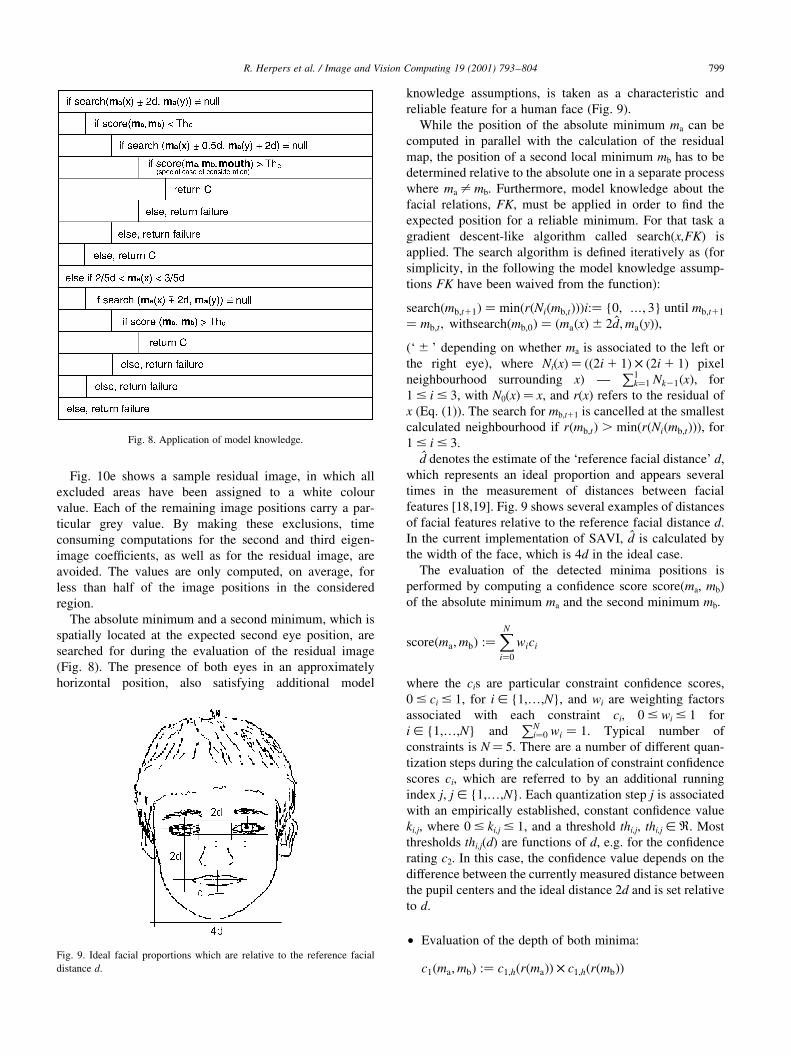
Fig. 10e shows a sample residual image, in which all
excluded areas have been assigned to a white colour
value. Each of the remaining image positions carry a par-
ticular grey value. By making these exclusions, time
consuming computations for the second and third eigen-
image coef®cients, as well as for the residual image, are
avoided. The values are only computed, on average, for
less than half of the image positions in the considered
region.
The absolute minimum and a second minimum, which is
spatially located at the expected second eye position, are
searched for during the evaluation of the residual image
(Fig. 8). The presence of both eyes in an approximately
horizontal position, also satisfying additional model
knowledge assumptions, is taken as a characteristic and
reliable feature for a human face (Fig. 9).
While the position of the absolute minimum ma can be
computed in parallel with the calculation of the residual
map, the position of a second local minimum mb has to be
determined relative to the absolute one in a separate process
where ma ± mb. Furthermore, model knowledge about the
facial relations, FK, must be applied in order to ®nd the
expected position for a reliable minimum. For that task a
gradient descent-like algorithm called search(x,FK) is
applied. The search algorithm is de®ned iteratively as (for
simplicity, in the following the model knowledge assump-
tions FK have been waived from the function):
search�mb;t11� � min�r�Ni�mb;t���i:� {0; ¼; 3} until mb;t11
� mb;t; withsearch�mb;0� � �ma�x�^ 2d̂;ma�y��;(` ^ ' depending on whether ma is associated to the left or
the right eye), where Ni(x)� ((2i 1 1) £ (2i 1 1) pixel
neighbourhood surrounding x) ÐP1
k�1 Nk21�x�; for
1 # i # 3, with N0(x)� x, and r(x) refers to the residual of
x (Eq. (1)). The search for mb,t11 is cancelled at the smallest
calculated neighbourhood if r�mb;t� . min�r�Ni�mb;t���; for
1 # i # 3.
dà denotes the estimate of the `reference facial distance' d,
which represents an ideal proportion and appears several
times in the measurement of distances between facial
features [18,19]. Fig. 9 shows several examples of distances
of facial features relative to the reference facial distance d.
In the current implementation of SAVI, dà is calculated by
the width of the face, which is 4d in the ideal case.
The evaluation of the detected minima positions is
performed by computing a con®dence score score(ma, mb)
of the absolute minimum ma and the second minimum mb.
score�ma;mb� :�XNi�0
wici
where the cis are particular constraint con®dence scores,
0 # ci # 1, for i [ {1,¼,N}, and wi are weighting factors
associated with each constraint ci, 0 # wi # 1 for
i [ {1,¼,N} andPN
i�0 wi � 1: Typical number of
constraints is N� 5. There are a number of different quan-
tization steps during the calculation of constraint con®dence
scores ci, which are referred to by an additional running
index j, j [ {1,¼,N}. Each quantization step j is associated
with an empirically established, constant con®dence value
ki,j, where 0 # ki,j # 1, and a threshold thi,j, thi,j [ R. Most
thresholds thi,j(d) are functions of d, e.g. for the con®dence
rating c2. In this case, the con®dence value depends on the
difference between the currently measured distance between
the pupil centers and the ideal distance 2d and is set relative
to d.
² Evaluation of the depth of both minima:
c1�ma;mb� :� c1;h�r�ma�� £ c1;h�r�mb��
R. Herpers et al. / Image and Vision Computing 19 (2001) 793±804 799
Fig. 8. Application of model knowledge.
Fig. 9. Ideal facial proportions which are relative to the reference facial
distance d.
where c1;h�r�xl�� :�k1;j;l; if r�xl� , th1;j;l
0; otherwise
(
and xl [ {ma;mb} and l :� {1; 2}:
² Distance between pupil centers:
c2�ma;mb� :�k2;j; if uu2d 2 uuma 2 mbuuuu , th2;j�d�0; otherwise
(
² Horizontal displacement of the pupil centers:
c3�ma;mb� :�k3;j; if uu face width
22 ma�x�1mb�x�
2uu , th3;j�d�
0; otherwise
(
² Vertical displacement of the pupil centers:
c4�ma;mb� :�k4;j; if uu face height
32 ma�y�1mb�y�
2uu , th4;j�d�
0; otherwise
8<:² Tilt of the eyes:
c5�ma;mb� :�k5;j; if uu arctan�uuma�y�1mb�y�uu�
uuma�x�1mb�x�uu uu , th5;j�d�0; otherwise
8<:During a possible postprocessing step, several additional
facial features of a more precise value can be examined in
more detail (see for instance Refs. [20,21]). To enable such
a processing, the facial region has to be zoomed in and
tracked appropriately. The tracking of the face will be
continued until either it disappears from the visual ®eld or
a particular command indicates a new action.
6. Hand detection
The process of hand detection starts when the supervisor
detects skin-tone blobs to the left of the currently attended
face (all gestures are assumed to be made with the right
hand). It is expected that the hand will be in a standard
pose, speci®cally the hand is upright, ®ngers outstretched,
and the palm is facing the camera. For each blob the super-
visor de®nes a region of interest (ROI) dependent on the
location of the face, and segments the image part into a
single connected skin-tone region. The red-channel image
of the segmented skin tone blob is then ®ltered using an
elongated and vertical oriented G2 ®lter [17] and one
oriented at 458. The ®lters are tuned to respond to spatial
objects about the expected width for a ®nger. Scale assump-
tions are derived from detected facial features. It is expected
that the three central ®ngers will produce strong responses
from the vertical ®lter, and that the thumb will produce a
strong response from the 458 ®lter.
Let IF represent the image ®ltered with the vertical
(®nger) ®lter, and IT represent the image ®ltered with the
458 (thumb) ®lter. Each ®ltered image is thresholded to
remove responses less than its average intensity value.
Next, IF is searched to ®nd the three largest responses.
The search algorithm ®nds a maximum, reports its location,
and then `removes' it by deleting all pixels from around the
maximum until a bounding valley is found (thus removing the
`hill' corresponding to the maximum). When the search is
repeated, it will ®nd the next largest peak, etc. In a similar
fashion, the location of the maximum response in the right
R. Herpers et al. / Image and Vision Computing 19 (2001) 793±804800
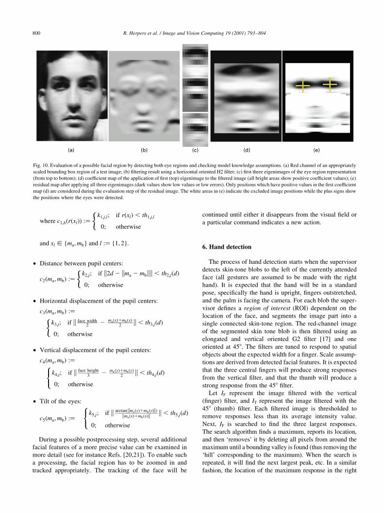
Fig. 10. Evaluation of a possible facial region by detecting both eye regions and checking model knowledge assumptions. (a) Red channel of an appropriately
scaled bounding box region of a test image; (b) ®ltering result using a horizontal oriented H2 ®lter; (c) ®rst three eigenimages of the eye region representation
(from top to bottom); (d) coef®cient map of the application of ®rst (top) eigenimage to the ®ltered image (all bright areas show positive coef®cient values); (e)
residual map after applying all three eigenimages (dark values show low values or low errors). Only positions which have positive values in the ®rst coef®cient
map (d) are considered during the evaluation step of the residual image. The white areas in (e) indicate the excluded image positions while the plus signs show
the positions where the eyes were detected.
third of IT is determined. Designate the locations of the three
peak responses from IF as j1, j2, and j3, where j1� ( f1x, f1y)T,
etc. These location vectors are ordered so that j3x $ j2x $ j1x.
Likewise designate the locations of the two maximum
responses in the right third of IT as t1 and t2. (Two peaks are
used by the thumb scoring function to ensure that a dominant
peak is present.) The locations of the IF maxima are then
checked applying additional model knowledge assumptions.
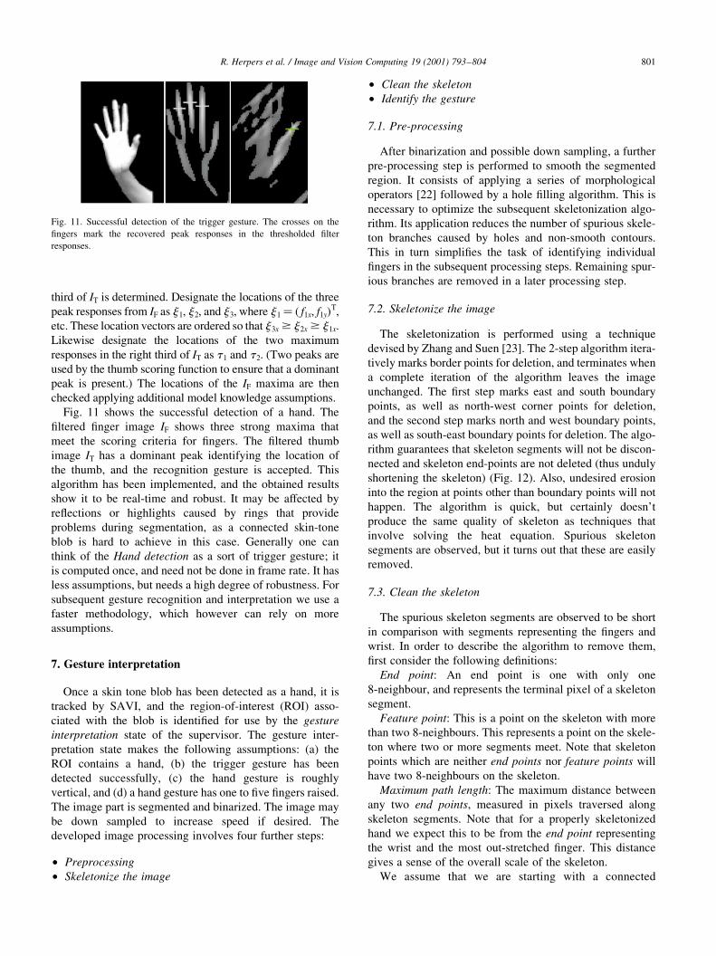
Fig. 11 shows the successful detection of a hand. The
®ltered ®nger image IF shows three strong maxima that
meet the scoring criteria for ®ngers. The ®ltered thumb
image IT has a dominant peak identifying the location of
the thumb, and the recognition gesture is accepted. This
algorithm has been implemented, and the obtained results
show it to be real-time and robust. It may be affected by
re¯ections or highlights caused by rings that provide
problems during segmentation, as a connected skin-tone
blob is hard to achieve in this case. Generally one can
think of the Hand detection as a sort of trigger gesture; it
is computed once, and need not be done in frame rate. It has
less assumptions, but needs a high degree of robustness. For
subsequent gesture recognition and interpretation we use a
faster methodology, which however can rely on more
assumptions.
7. Gesture interpretation
Once a skin tone blob has been detected as a hand, it is
tracked by SAVI, and the region-of-interest (ROI) asso-
ciated with the blob is identi®ed for use by the gesture
interpretation state of the supervisor. The gesture inter-
pretation state makes the following assumptions: (a) the
ROI contains a hand, (b) the trigger gesture has been
detected successfully, (c) the hand gesture is roughly
vertical, and (d) a hand gesture has one to ®ve ®ngers raised.
The image part is segmented and binarized. The image may
be down sampled to increase speed if desired. The
developed image processing involves four further steps:
² Preprocessing
² Skeletonize the image
² Clean the skeleton
² Identify the gesture
7.1. Pre-processing
After binarization and possible down sampling, a further
pre-processing step is performed to smooth the segmented
region. It consists of applying a series of morphological
operators [22] followed by a hole ®lling algorithm. This is
necessary to optimize the subsequent skeletonization algo-
rithm. Its application reduces the number of spurious skele-
ton branches caused by holes and non-smooth contours.
This in turn simpli®es the task of identifying individual
®ngers in the subsequent processing steps. Remaining spur-
ious branches are removed in a later processing step.
7.2. Skeletonize the image
The skeletonization is performed using a technique
devised by Zhang and Suen [23]. The 2-step algorithm itera-
tively marks border points for deletion, and terminates when
a complete iteration of the algorithm leaves the image
unchanged. The ®rst step marks east and south boundary
points, as well as north-west corner points for deletion,
and the second step marks north and west boundary points,
as well as south-east boundary points for deletion. The algo-
rithm guarantees that skeleton segments will not be discon-
nected and skeleton end-points are not deleted (thus unduly
shortening the skeleton) (Fig. 12). Also, undesired erosion
into the region at points other than boundary points will not
happen. The algorithm is quick, but certainly doesn't
produce the same quality of skeleton as techniques that
involve solving the heat equation. Spurious skeleton
segments are observed, but it turns out that these are easily
removed.
7.3. Clean the skeleton
The spurious skeleton segments are observed to be short
in comparison with segments representing the ®ngers and
wrist. In order to describe the algorithm to remove them,
®rst consider the following de®nitions:
End point: An end point is one with only one
8-neighbour, and represents the terminal pixel of a skeleton
segment.
Feature point: This is a point on the skeleton with more
than two 8-neighbours. This represents a point on the skele-
ton where two or more segments meet. Note that skeleton
points which are neither end points nor feature points will
have two 8-neighbours on the skeleton.
Maximum path length: The maximum distance between
any two end points, measured in pixels traversed along
skeleton segments. Note that for a properly skeletonized
hand we expect this to be from the end point representing
the wrist and the most out-stretched ®nger. This distance
gives a sense of the overall scale of the skeleton.
We assume that we are starting with a connected
R. Herpers et al. / Image and Vision Computing 19 (2001) 793±804 801
Fig. 11. Successful detection of the trigger gesture. The crosses on the
®ngers mark the recovered peak responses in the thresholded ®lter
responses.
skeleton. For each end point on the skeleton we evalu-
ate the path length from that end point to a feature
point. The end-point/feature-point pair de®nes a skele-
ton segment. If the length of this segment is less than
10% of the maximum path length, the segment is
removed. Note that when determining the length of a
segment, if we start at an end point and arrive at
another end point without encountering a feature
point, then either the skeleton is a simple line, or the
assumption of a connected skeleton has been violated.
In either case an error is ¯agged and the gesture inter-
pretation fails. However, since we assume we start with
a connected skin-tone region, this situation should never
be encountered in practice.
7.4. Identify the gesture using model knowledge
This part of the gesture recognition involves examining
end points to see if they correspond to potential ®ngers or a
thumb. The current algorithm assigns segments to be ®ngers
or thumbs based on the position of their end points. For each
end point, it is ®rst checked to see if it is a thumb. Let
r � (px,py)T be the location of an end point, and let w and
h be the width and height, respectively, of the ROI. An end
point is considered to be a thumb if px $ 2w/3 and h/
4 # py # 3h/4. Any end point which is not considered a
thumb is considered a ®nger if py # h/3. If more than one
end point is identi®ed as a potential thumb, or if the number
of ®nger candidates is zero or greater than four, then the
gesture identi®cation fails. Note that this requires that the
ROI bounding the hand skin-tone blob be accurately deter-
mined prior to invoking the algorithm. Finally, it should be
mentioned that even if the thumb is not found, a valid
gesture can be identi®ed.
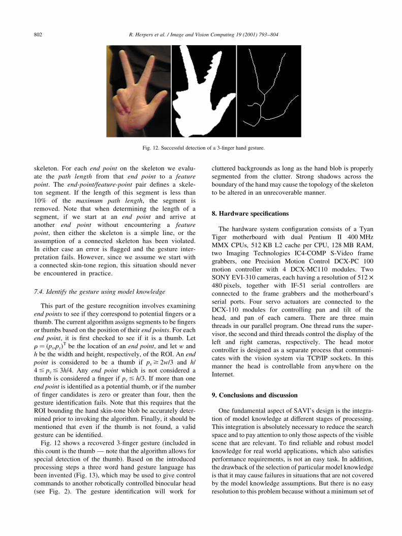
Fig. 12 shows a recovered 3-®nger gesture (included in
this count is the thumb Ð note that the algorithm allows for
special detection of the thumb). Based on the introduced
processing steps a three word hand gesture language has
been invented (Fig. 13), which may be used to give control
commands to another robotically controlled binocular head
(see Fig. 2). The gesture identi®cation will work for
cluttered backgrounds as long as the hand blob is properly
segmented from the clutter. Strong shadows across the
boundary of the hand may cause the topology of the skeleton
to be altered in an unrecoverable manner.
8. Hardware speci®cations
The hardware system con®guration consists of a Tyan
Tiger motherboard with dual Pentium II 400 MHz
MMX CPUs, 512 KB L2 cache per CPU, 128 MB RAM,
two Imaging Technologies IC4-COMP S-Video frame
grabbers, one Precision Motion Control DCX-PC 100
motion controller with 4 DCX-MC110 modules. Two
SONY EVI-310 cameras, each having a resolution of 512 £480 pixels, together with IF-51 serial controllers are
connected to the frame grabbers and the motherboard's
serial ports. Four servo actuators are connected to the
DCX-110 modules for controlling pan and tilt of the
head, and pan of each camera. There are three main
threads in our parallel program. One thread runs the super-
visor, the second and third threads control the display of the
left and right cameras, respectively. The head motor
controller is designed as a separate process that communi-
cates with the vision system via TCP/IP sockets. In this
manner the head is controllable from anywhere on the
Internet.
9. Conclusions and discussion
One fundamental aspect of SAVI's design is the integra-
tion of model knowledge at different stages of processing.
This integration is absolutely necessary to reduce the search
space and to pay attention to only those aspects of the visible
scene that are relevant. To ®nd reliable and robust model
knowledge for real world applications, which also satis®es
performance requirements, is not an easy task. In addition,
the drawback of the selection of particular model knowledge
is that it may cause failures in situations that are not covered
by the model knowledge assumptions. But there is no easy
resolution to this problem because without a minimum set of
R. Herpers et al. / Image and Vision Computing 19 (2001) 793±804802
Fig. 12. Successful detection of a 3-®nger hand gesture.
constraints and restrictions a real-time system on currently
modest hardware may be impossible.
To evaluate the performance of both hand gesture
processing modules a testing sequence has been
developed. The task was to show a two word hand gesture
language; ®rst the ®ve ®nger trigger gesture followed by a
arbitrary `®nger counting gesture'. For simplicity subjects
were asked to count ten times upwards and downwards. Ten
subjects performed the sequence and everybody showed
in total 100 `®nger counting gestures'. During the evaluation
of the results we distinguished between hand gestures shown
including and excluding the thumb, because the system is
designed to determine if the thumb is raised or not.
We obtained an overall correct `®nger counting rate' of
95.4%. The individual rates for the several numbers of
®ngers raised differ signi®cantly. If two ®ngers are raised
the obtained detection rate was 100% regardless if the
thumb was raised or not. Nearly the same results could be
obtained for the three ®nger gesture. For the ®ve ®nger
gesture we obtained a detection rate of 90%, in most cases
the pinkie ®nger wasn't detected correctly. Showing just
one ®nger was also not so successful with 94.5% because
the segmentation failed due to shadows. For the four ®nger
gesture the detection rate including the thumb was signi®-
cantly higher with 96.9%, in contrast to the gesture exclud-
ing the thumb of 92.2%. Much of the success of the
algorithm depends on good segmentation of the skin-tone
blob. To date this has worked well against cluttered back-
grounds and during tracking (Fig. 14).
SAVI is still under construction and changes may be
necessary to improve its performance. But the general
underlying idea of SAVI will remain the same. Static vision
systems, which do not enable any kind of reaction to
changing conditions, will be replaced by more sophisticated
R. Herpers et al. / Image and Vision Computing 19 (2001) 793±804 803
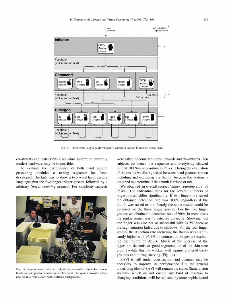
Fig. 13. Three word language developed to control a second binocular stereo head.
Fig. 14. System setup with wo robotically controlled binocular camera
heads and an operator who has raised her hand. The system provides robust
and reliable results even with cluttered backgrounds.
solutions incorporating a particular set of active behaviors
needed to cope with more speci®c and/or extensive applica-
tions. The set of actions provided by these new systems is
then mainly dependent on the task or application and the
environment for which they are designed.
Acknowledgements
We thank the many students and staff members at York
University and the University of Toronto who have con-
tributed: Lee Chang, Chakra Chennubhotla, Karine
Darcourt, Laura Hopkins, Jonathan Kaufman, Andrea
Levin, Rob McCready, Caroline Pantofaru, Douglas
Topalovic, Cathrine Stinson, Joyce Wong, Laura Wood,
Nancy Yuen. Development of SAVI has been funded by
IRIS (Institute for Robotics and Intelligent Systems, a
Government of Canada Network of Centres of Excellence),
NSERC (the Natural Science and Engineering Council of
Canada) and IBM Canada, Centre of Advanced Studies. R.
Herpers acknowledges the support of the Deutsche
Forschungsgemeinschaft (DFG), Grant: He-2967/1-1 and
the German Academic Exchange Service (DAAD) Grant:
222-stpd-III-23/00-cdn.
References
[1] E. Milios, M. Jenkin, J.K. Tsotsos, Design and performance of trish, a
binocular robot head with torsional eye movements, IJPRAI 7 (1)
(1993) 51±68.
[2] J.K. Tsotsos, G. Verghese, S. Dickinson, M. Jenkin, A. Jepson, E.
Milios, S. Stevenson, M. Black, D. Metaxas, S. Culhane, Y. Ye, R.
Mann, Playbot a visually-guided robot for physically disabled chil-
dren, IVC 19 (1998) 275±292.
[3] C.R. Wren, A. Azarbayejani, T. Darrell, A. Pentland, P®nder: real-
time tracking of the human body, IEEE Trans. PAMI 19 (7) (1997)
780±785.
[4] M. Lucente, G.-J. Zwart, A.D. George, Visualization space: a testbed
for deviceless multimodal user interfaces, Intelligent Environments
Symposium `98, AAAI Spring Symposium, 1998.
[5] J. Cai, A. Goshtasby, C. Yu, Detecting human faces in color images,
in: International Workshop on Multi-Media Database Management
Systems, 1998.
[6] Y. Raja, S.J. Mckenna, S. Gong, Tracking and segmenting people in
varying lighting conditions using colour, in: Third International
Conference on Automatic Face and Gesture Recognition, Nara,
Japan, IEEE Computer Society Press, 1998, pp. 228±233.
[7] R. Kjeldsen, J. Kender, Finding skin in colour images, in: Proceedings
of the IEEE International Conference on Automatic Face and Gesture
Recognition, 1996, pp. 312±317.
[8] R. Kjeldsen, J. Kender, Visual hand gesture recognition for window
system control, in: Proceedings of the International Workshop on
Automatic Face and Gesture Recognition, 1995, pp. 184±188.
[9] R. Kjeldsen, J. Kender, Toward the use of gesture in traditional user
interfaces, in: Proceedings of the IEEE International Conference on
Automatic Face and Gesture Recognition, IEEE, 1996, pp. 151±156.
[10] W.T. Freeman, C. Weissman, Television control by hand gestures, in:
Proceedings of the International Workship on Automatic Face and
Gesture Recognition, 1995, pp. 179±183.
[11] W.T. Freeman, K. Tanaka, J. Ohta, K. Kyuma, Computer vision
for computer games, in: Proceedings of the IEEE International
Conference on Face and Gesture Recognition, 1996, pp. 100±105.
[12] A. Utsumi, Jun Ohya, Multiple-hand-gesture tracking using multiple
cameras, in: Proceedings of the IEEE Computer Society Conference
on Computer Vision and Pattern Recognition, vol. 1, 1999, pp. 473±
478.
[13] R. Hamdam, F. Heitz, L. Thoraval, Gesture localization and recogni-
tion using probabilistic visual learning, in: Proceedings of the IEEE
Computer Society Conference on Computer Vision and Pattern
Recognition, vol. 2, 1999, pp. 98±103.
[14] C. Jennings, Robust ®nger tracking with multiple cameras, Proceed-
ings of the IEEE International Workshop on Recognition, Analysis
and Tracking of Faces and Gestures in Real-Time Systems, 1999,
pp. 152±160.
[15] R. Herpers, G. Verghese, K. Derpanis, R. McCready, J. Maclean, A.
Levin, D. Topalovic, L. Wood, A. Jepson, Detection and tracking of
faces in real environments, in: Proceedings of the IEEE International
Workshop on Recognition, Analysis and Tracking of Faces and
Gestures in Real-Time Systems, 1999, pp. 96±104.
[16] M. Turk, A. Pentland, Eigenfaces for recognition, J. Cogn. Neurosci.
3 (1991) 71±86.
[17] W.T. Freeman, E.H. Adelson, The design and use of steerable ®lters
for image analysis, IEEE Trans. PAMI 13 (1991) 891±906.
[18] L. da Vinci, Treatise on Painting, Vol. 1, Princteon University Press,
Princeton, New Jersey, 1550.
[19] R. Herpers, GAZE: a common attentive processing strategy for the
detection and investigation of salient image regions, Tech-Rep. No.
9714, University of Kiel, Germany, 1997.
[20] R. Herpers, H. Kattner, H. Rodax, G. Sommer, GAZE: an attentional
processing strategy to detect and analyze the prominent facial regions,
in: M. Bichsel (Ed.), International Workshop on Automatic Face- and
Gesture-Recognition, Zurich, Switzerland, 1995, pp. 214±220.
[21] R. Herpers, M. Michaelis, K.H. Lichtenauer, G. Sommer, Edge
and keypoint detection in facial regions, in: Second International
Conference on Automatic Face and Gesture Recognition, Killington,
Vermont, IEEE Computer Society Press, 1996, pp. 212±217.
[22] R. Klette, P. Zamperoni, Handbook of Image Processing Operators,
J. Wiley and Sons, 1996.
[23] T.Y. Zhang, C. Suen, A fast parallel algorithm for thinning digital
patterns, Comm. ACM 27 (3) (1984) 236±239.
R. Herpers et al. / Image and Vision Computing 19 (2001) 793±804804


![The impact of resource title on tags in collaborative tagging …web.cs.dal.ca/~eem/cvWeb/pubs/titleToTag-ht65-lipczak... · 2010-04-13 · The collaborative model [5, 7, 10, 23]](https://img.pdfslide.net/doc/110x75/5e7dcf956b74d718f3141cb6/the-impact-of-resource-title-on-tags-in-collaborative-tagging-webcsdalcaeemcvwebpubstitletotag-ht65-lipczak.jpg)