Embed Size (px)
DESCRIPTION
artcam
Citation preview
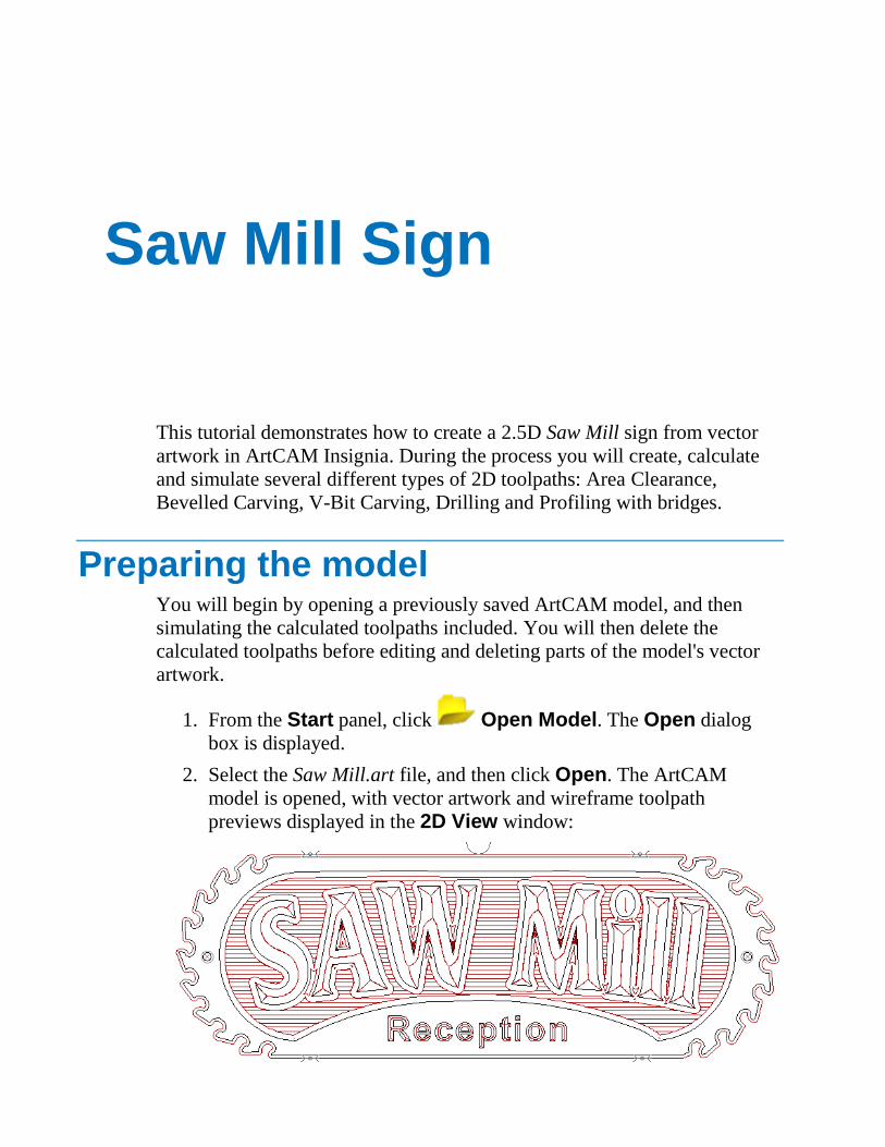
This tutorial demonstrates how to create a 2.5D Saw Mill sign from vector
artwork in ArtCAM Insignia. During the process you will create, calculate
and simulate several different types of 2D toolpaths: Area Clearance,
Bevelled Carving, V-Bit Carving, Drilling and Profiling with bridges.
Preparing the model You will begin by opening a previously saved ArtCAM model, and then
simulating the calculated toolpaths included. You will then delete the
calculated toolpaths before editing and deleting parts of the model's vector
artwork.
1. From the Start panel, click Open Model. The Open dialog
box is displayed.
2. Select the Saw Mill.art file, and then click Open. The ArtCAM
model is opened, with vector artwork and wireframe toolpath
previews displayed in the 2D View window:
Saw Mill Sign
3. From the Project panel, click to the right of Toolpaths in the
Project Tree. The wireframe toolpath previews are hidden in the 2D View window; leaving only the vector artwork shown.
4. Press the F3 key to display the 3D View window. The material block
is displayed along with the zero plane. No toolpaths are shown.
5. From the Project panel, click beside Toolpaths in the Project
Tree to show the Area Clear, Bevelled Carving, V-Bit
Carving, Drilling and Profile toolpaths.
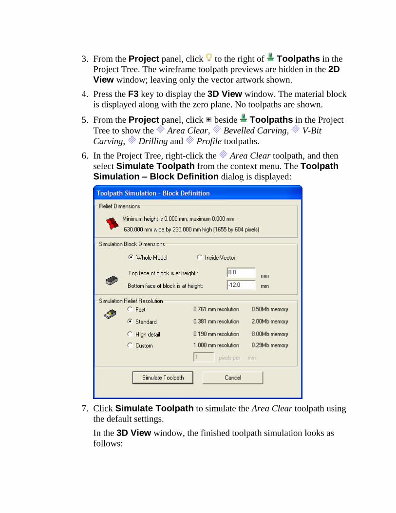
6. In the Project Tree, right-click the Area Clear toolpath, and then
select Simulate Toolpath from the context menu. The Toolpath Simulation – Block Definition dialog is displayed:
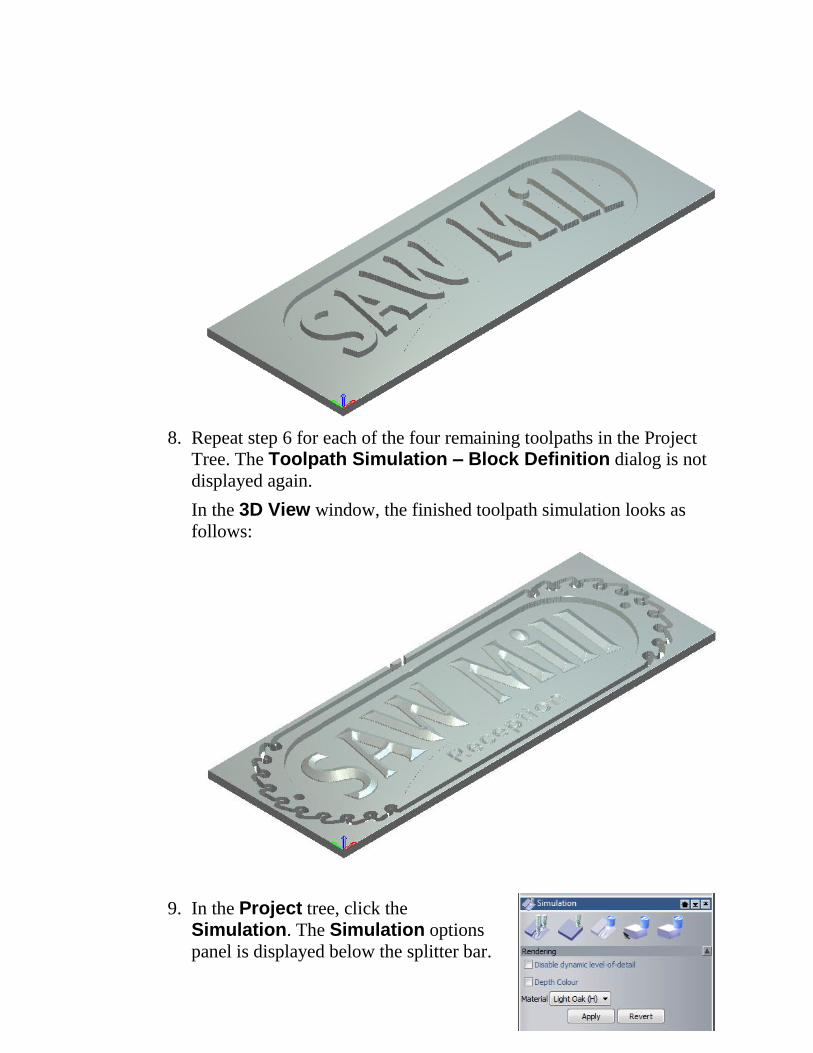
7. Click Simulate Toolpath to simulate the Area Clear toolpath using
the default settings.
In the 3D View window, the finished toolpath simulation looks as
follows:
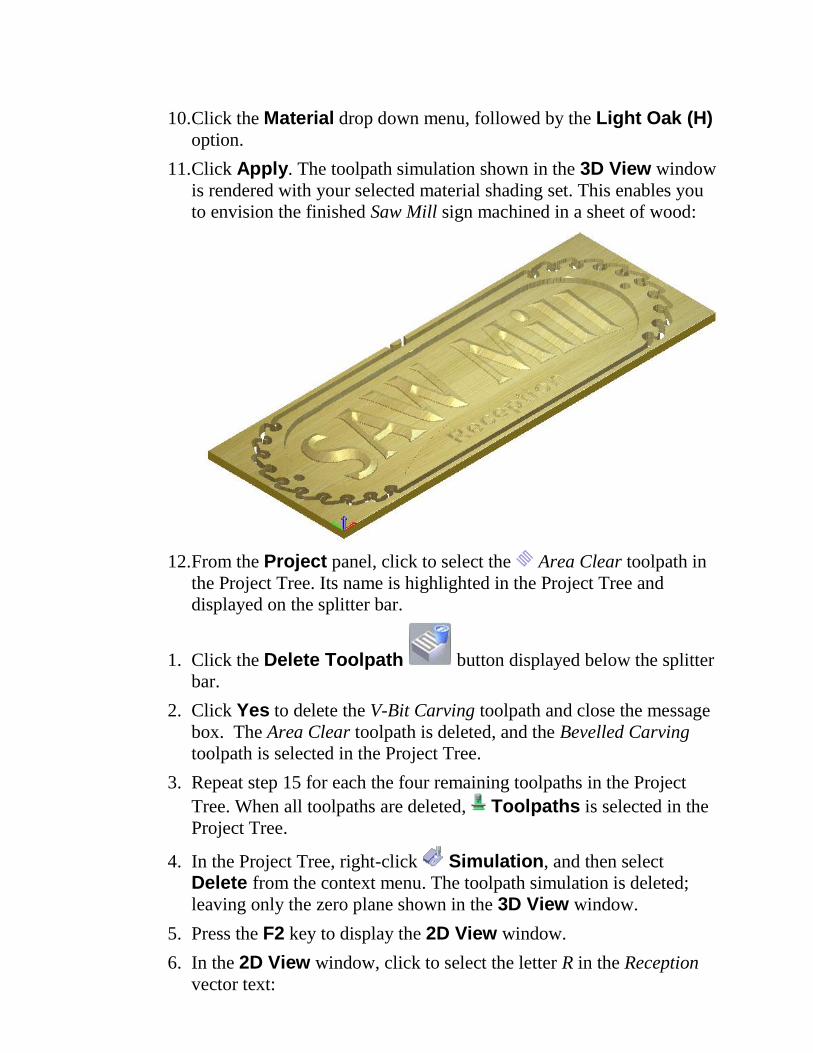
8. Repeat step 6 for each of the four remaining toolpaths in the Project
Tree. The Toolpath Simulation – Block Definition dialog is not
displayed again.
In the 3D View window, the finished toolpath simulation looks as
follows:
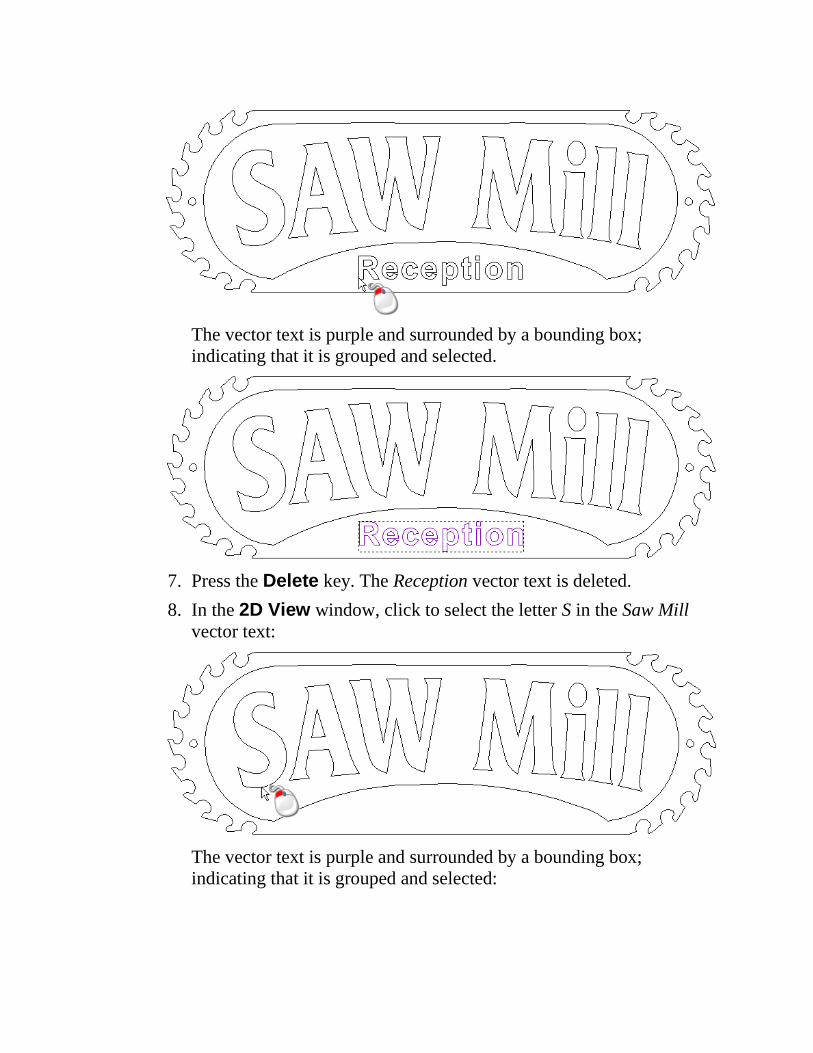
9. In the Project tree, click the
Simulation. The Simulation options
panel is displayed below the splitter bar.
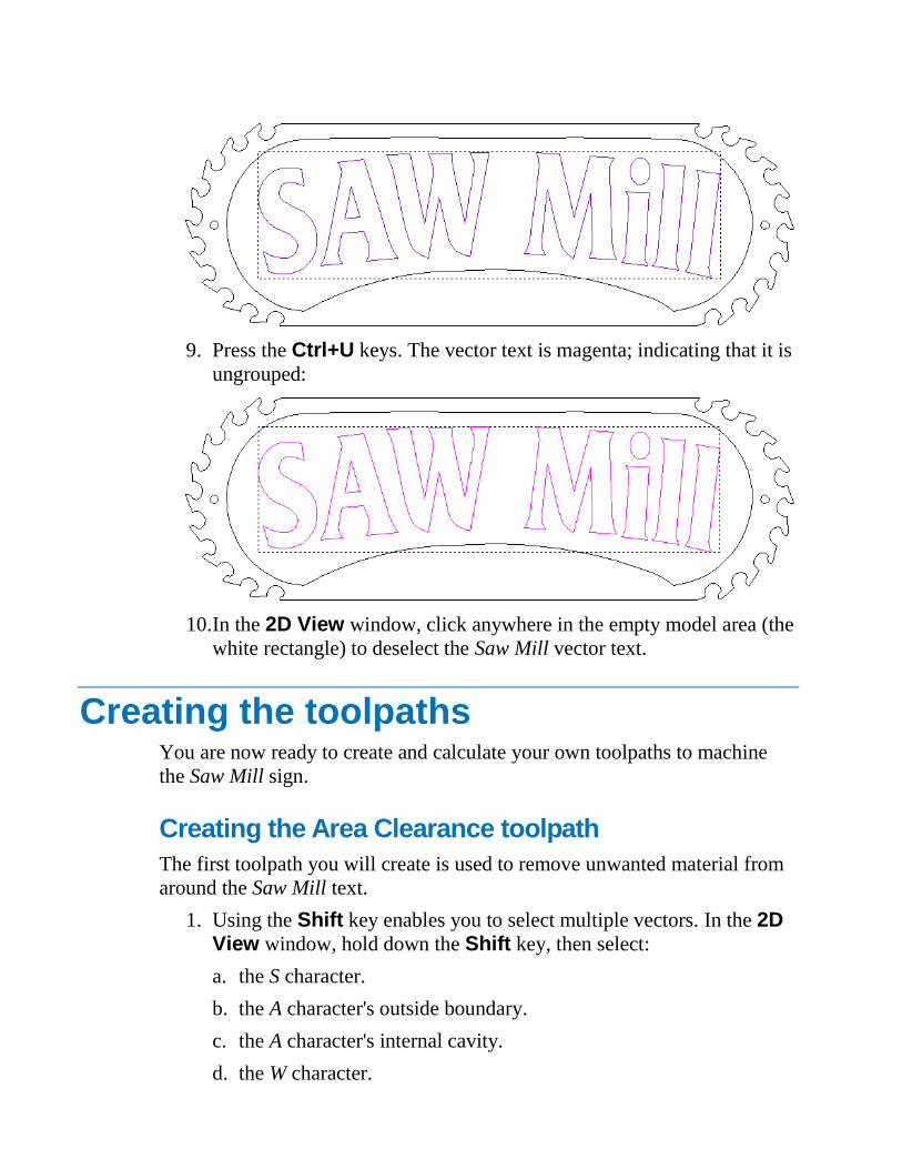
10. Click the Material drop down menu, followed by the Light Oak (H) option.
11. Click Apply. The toolpath simulation shown in the 3D View window
is rendered with your selected material shading set. This enables you
to envision the finished Saw Mill sign machined in a sheet of wood:
12. From the Project panel, click to select the Area Clear toolpath in
the Project Tree. Its name is highlighted in the Project Tree and
displayed on the splitter bar.
1. Click the Delete Toolpath button displayed below the splitter
bar.
2. Click Yes to delete the V-Bit Carving toolpath and close the message
box. The Area Clear toolpath is deleted, and the Bevelled Carving
toolpath is selected in the Project Tree.
3. Repeat step 15 for each the four remaining toolpaths in the Project
Tree. When all toolpaths are deleted, Toolpaths is selected in the
Project Tree.
4. In the Project Tree, right-click Simulation, and then select
Delete from the context menu. The toolpath simulation is deleted;
leaving only the zero plane shown in the 3D View window.
5. Press the F2 key to display the 2D View window.
6. In the 2D View window, click to select the letter R in the Reception
vector text:
The vector text is purple and surrounded by a bounding box;
indicating that it is grouped and selected.
7. Press the Delete key. The Reception vector text is deleted.
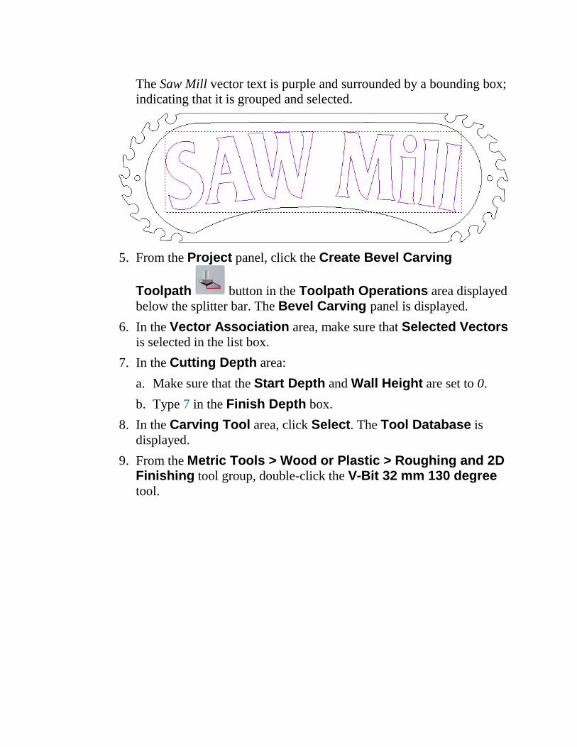
8. In the 2D View window, click to select the letter S in the Saw Mill
vector text:
The vector text is purple and surrounded by a bounding box;
indicating that it is grouped and selected:
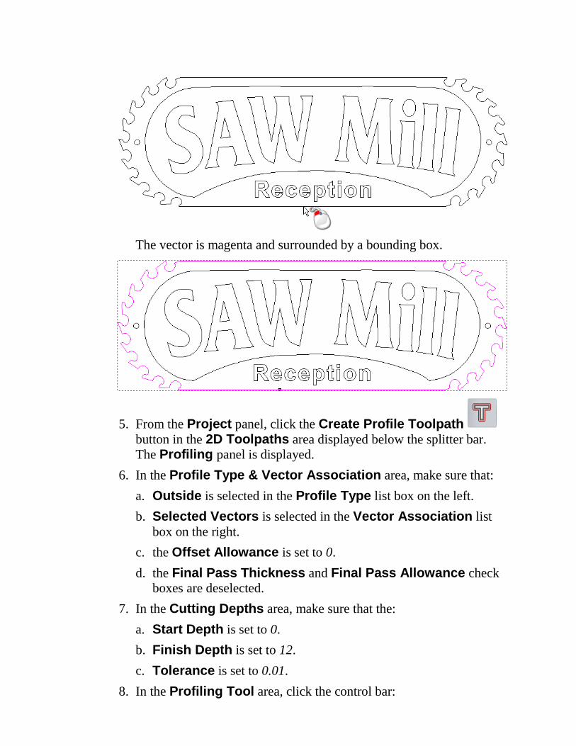
9. Press the Ctrl+U keys. The vector text is magenta; indicating that it is
ungrouped:
10. In the 2D View window, click anywhere in the empty model area (the
white rectangle) to deselect the Saw Mill vector text.
Creating the toolpaths You are now ready to create and calculate your own toolpaths to machine
the Saw Mill sign.
Creating the Area Clearance toolpath
The first toolpath you will create is used to remove unwanted material from
around the Saw Mill text.
1. Using the Shift key enables you to select multiple vectors. In the 2D View window, hold down the Shift key, then select:
a. the S character.
b. the A character's outside boundary.
c. the A character's internal cavity.
d. the W character.
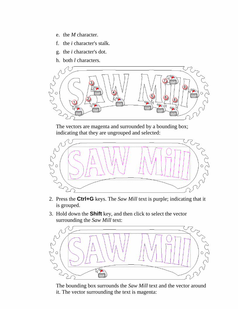
e. the M character.
f. the i character's stalk.
g. the i character's dot.
h. both l characters.
The vectors are magenta and surrounded by a bounding box;
indicating that they are ungrouped and selected:
2. Press the Ctrl+G keys. The Saw Mill text is purple; indicating that it
is grouped.
3. Hold down the Shift key, and then click to select the vector
surrounding the Saw Mill text:
The bounding box surrounds the Saw Mill text and the vector around
it. The vector surrounding the text is magenta:
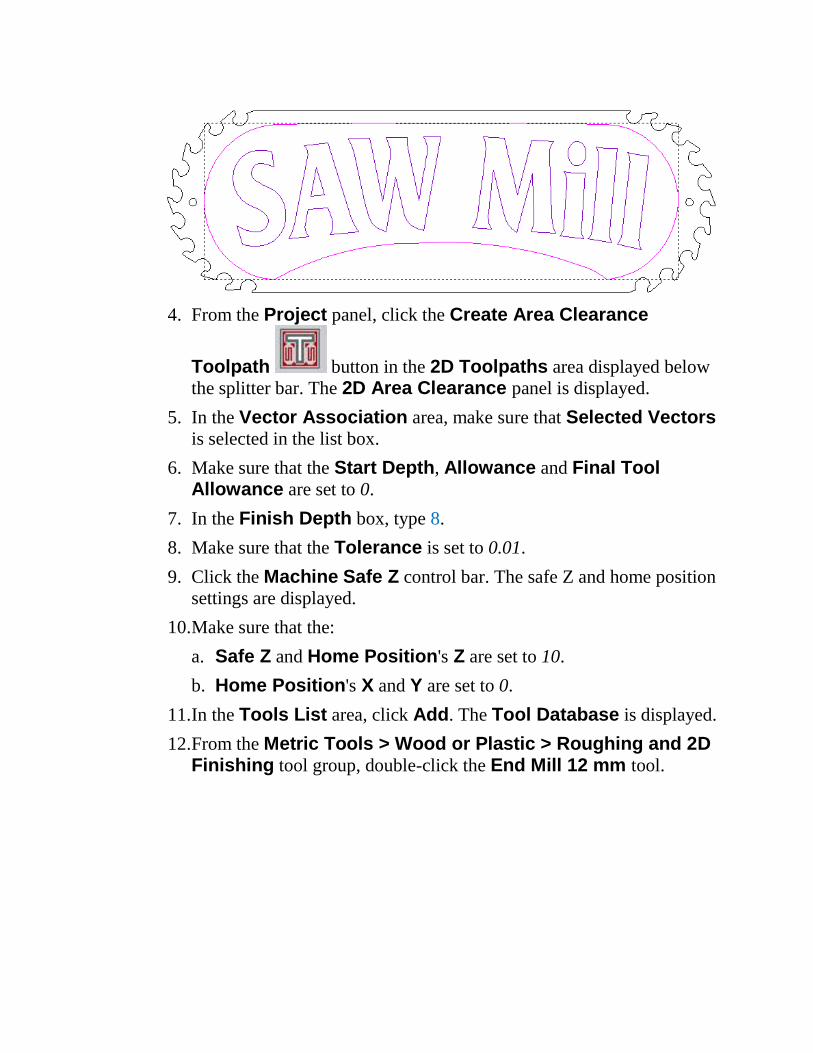
4. From the Project panel, click the Create Area Clearance
Toolpath button in the 2D Toolpaths area displayed below
the splitter bar. The 2D Area Clearance panel is displayed.
5. In the Vector Association area, make sure that Selected Vectors
is selected in the list box.
6. Make sure that the Start Depth, Allowance and Final Tool Allowance are set to 0.
7. In the Finish Depth box, type 8.
8. Make sure that the Tolerance is set to 0.01.
9. Click the Machine Safe Z control bar. The safe Z and home position
settings are displayed.
10. Make sure that the:
a. Safe Z and Home Position's Z are set to 10.
b. Home Position's X and Y are set to 0.
11. In the Tools List area, click Add. The Tool Database is displayed.
12. From the Metric Tools > Wood or Plastic > Roughing and 2D Finishing tool group, double-click the End Mill 12 mm tool.
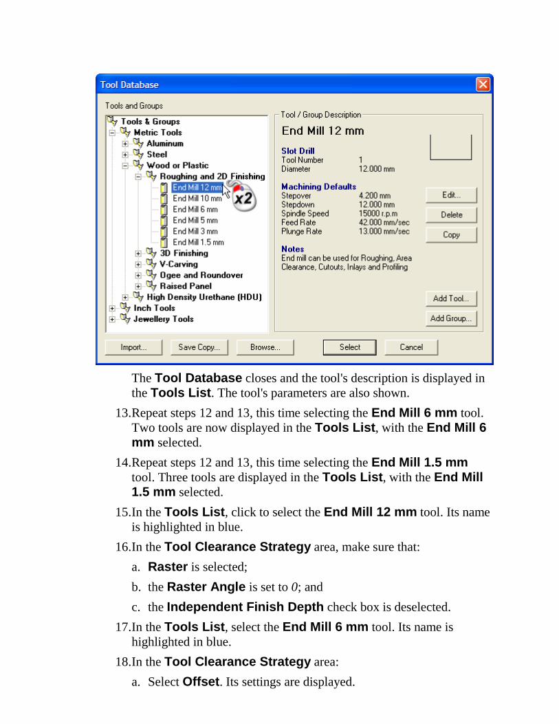
The Tool Database closes and the tool's description is displayed in
the Tools List. The tool's parameters are also shown.
13. Repeat steps 12 and 13, this time selecting the End Mill 6 mm tool.
Two tools are now displayed in the Tools List, with the End Mill 6 mm selected.
14. Repeat steps 12 and 13, this time selecting the End Mill 1.5 mm
tool. Three tools are displayed in the Tools List, with the End Mill 1.5 mm selected.
15. In the Tools List, click to select the End Mill 12 mm tool. Its name
is highlighted in blue.
16. In the Tool Clearance Strategy area, make sure that:
a. Raster is selected;
b. the Raster Angle is set to 0; and
c. the Independent Finish Depth check box is deselected.
17. In the Tools List, select the End Mill 6 mm tool. Its name is
highlighted in blue.
18. In the Tool Clearance Strategy area:
a. Select Offset. Its settings are displayed.
b. Make sure that the Cut Direction is set to Climb Mill.
c. Make sure that the Start Point is set to Inside.
d. Make sure that the Independent Finish Depth check box is
deselected.
19. Repeat step 16, this time selecting the End Mill 1.5 mm tool in the
Tools List.
20. Make sure that the Add Ramping Moves check box is deselected.
21. In the Material area, click Setup. The Material Setup dialog is
displayed:
22. Make sure that the:
a. Material Thickness is set to 12.
b. Material Z Zero is set to the top of the material block.
c. Model Position In Material is set to the top of the material
block.
23. Click OK to close the Material Setup dialog box.
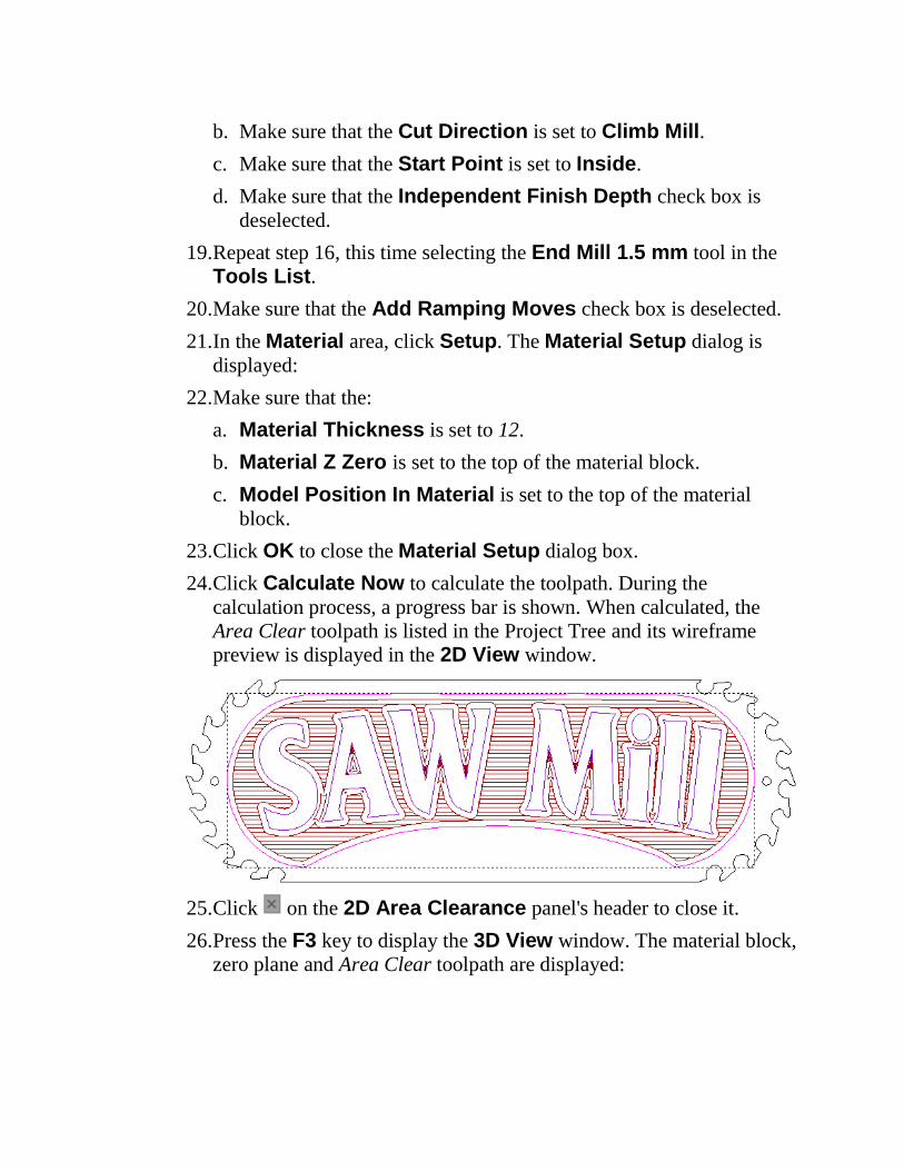
24. Click Calculate Now to calculate the toolpath. During the
calculation process, a progress bar is shown. When calculated, the
Area Clear toolpath is listed in the Project Tree and its wireframe
preview is displayed in the 2D View window.
25. Click on the 2D Area Clearance panel's header to close it.
26. Press the F3 key to display the 3D View window. The material block,
zero plane and Area Clear toolpath are displayed:
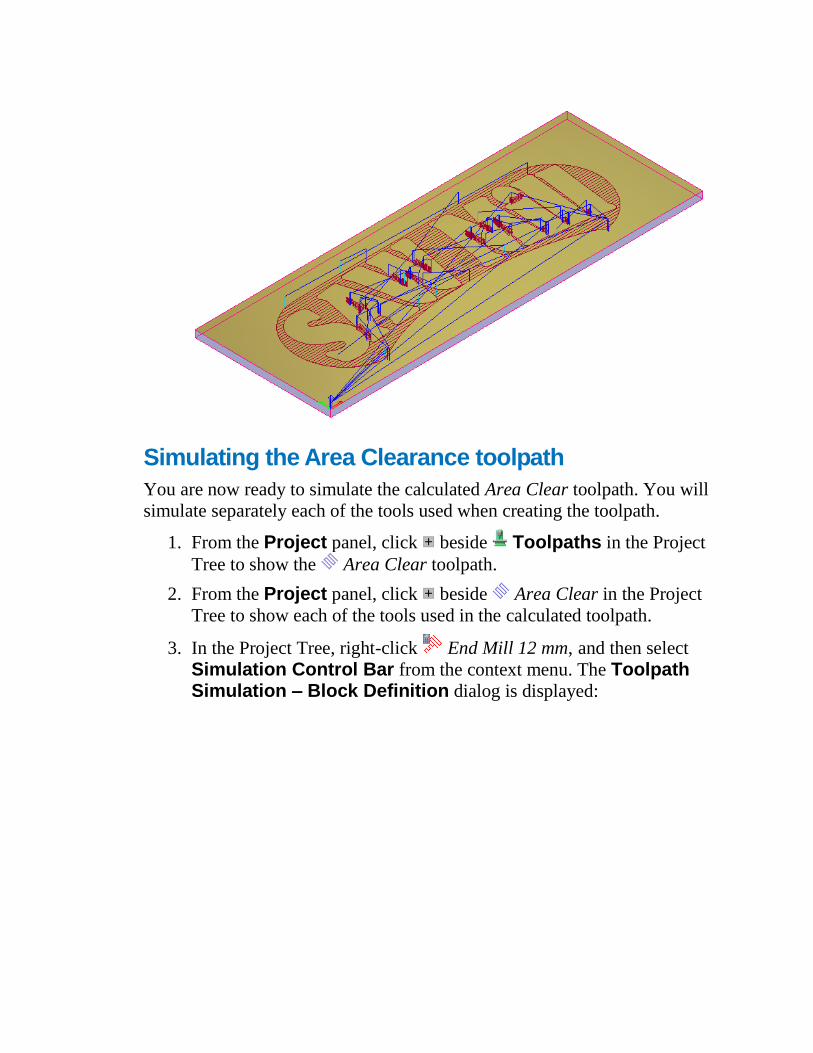
Simulating the Area Clearance toolpath
You are now ready to simulate the calculated Area Clear toolpath. You will
simulate separately each of the tools used when creating the toolpath.
1. From the Project panel, click beside Toolpaths in the Project
Tree to show the Area Clear toolpath.
2. From the Project panel, click beside Area Clear in the Project
Tree to show each of the tools used in the calculated toolpath.
3. In the Project Tree, right-click End Mill 12 mm, and then select
Simulation Control Bar from the context menu. The Toolpath Simulation – Block Definition dialog is displayed:
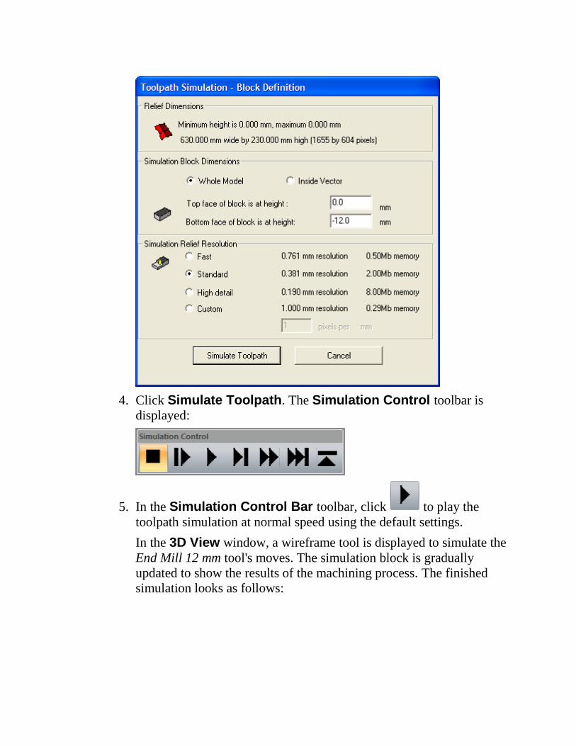
4. Click Simulate Toolpath. The Simulation Control toolbar is
displayed:
5. In the Simulation Control Bar toolbar, click to play the
toolpath simulation at normal speed using the default settings.
In the 3D View window, a wireframe tool is displayed to simulate the
End Mill 12 mm tool's moves. The simulation block is gradually
updated to show the results of the machining process. The finished
simulation looks as follows:
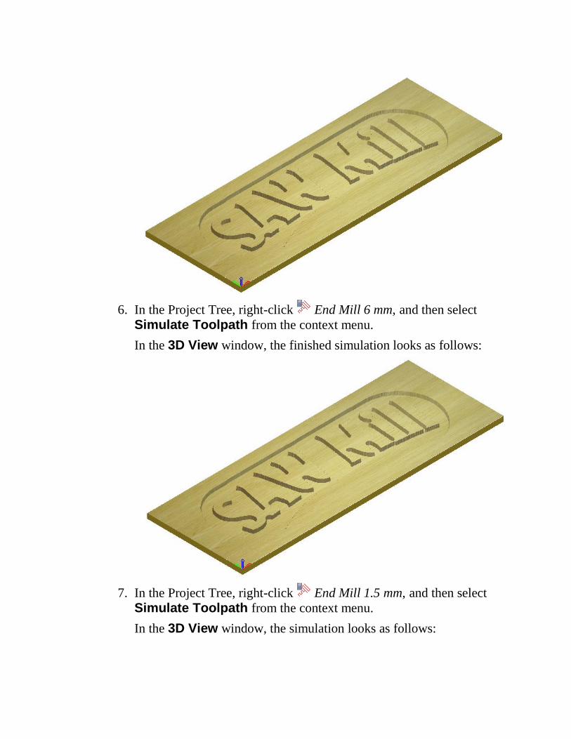
6. In the Project Tree, right-click End Mill 6 mm, and then select
Simulate Toolpath from the context menu.
In the 3D View window, the finished simulation looks as follows:
7. In the Project Tree, right-click End Mill 1.5 mm, and then select
Simulate Toolpath from the context menu.
In the 3D View window, the simulation looks as follows:
Creating the Bevelled Carving Toolpath
You are now ready to create the second toolpath in the model. This will be
used to create prismatic lettering in the Saw Mill sign.
1. Press the F2 key to display the 2D View window. The vector artwork
and the calculated Area Clear toolpath's wireframe preview are
displayed.
2. From the Project panel, click to the right of Area Clear in the
Project Tree. The wireframe toolpath preview is hidden in the 2D View window.
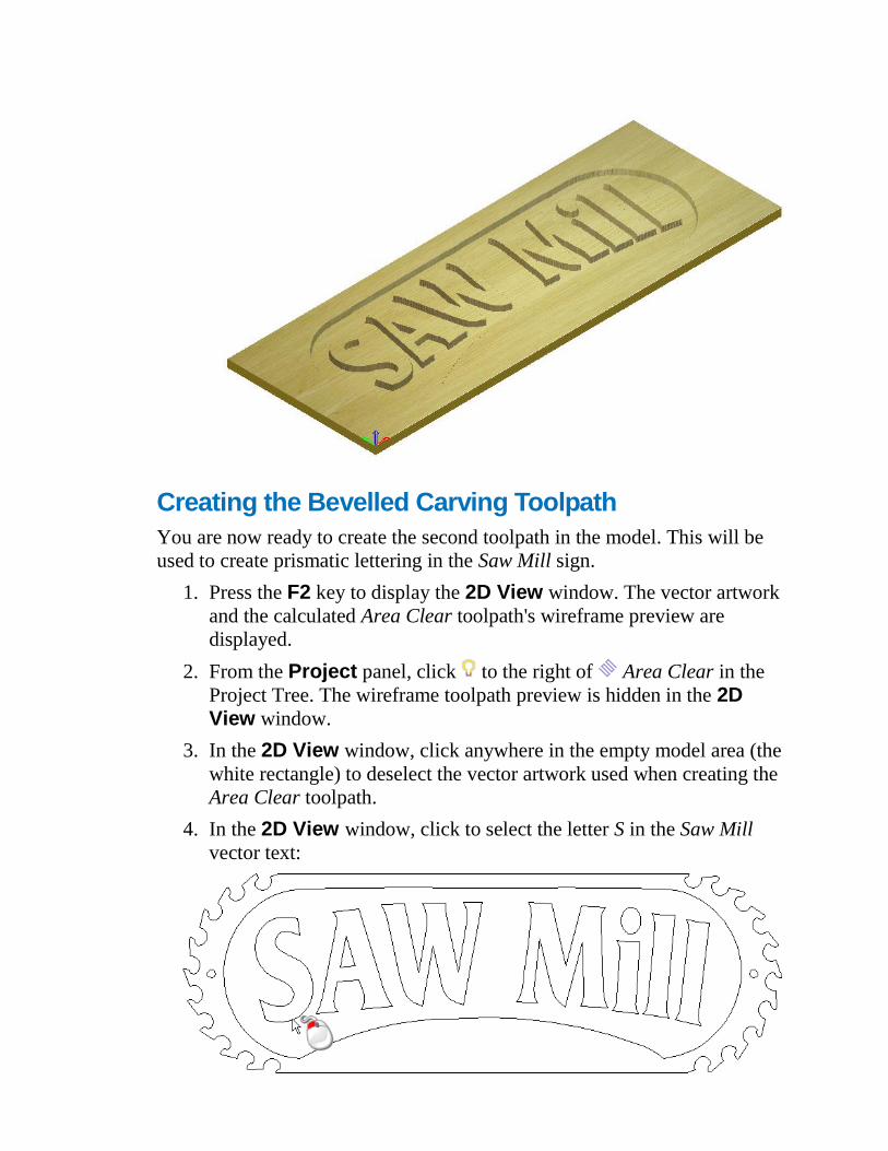
3. In the 2D View window, click anywhere in the empty model area (the
white rectangle) to deselect the vector artwork used when creating the
Area Clear toolpath.
4. In the 2D View window, click to select the letter S in the Saw Mill
vector text:
The Saw Mill vector text is purple and surrounded by a bounding box;
indicating that it is grouped and selected.
5. From the Project panel, click the Create Bevel Carving
Toolpath button in the Toolpath Operations area displayed
below the splitter bar. The Bevel Carving panel is displayed.
6. In the Vector Association area, make sure that Selected Vectors
is selected in the list box.
7. In the Cutting Depth area:
a. Make sure that the Start Depth and Wall Height are set to 0.
b. Type 7 in the Finish Depth box.
8. In the Carving Tool area, click Select. The Tool Database is
displayed.
9. From the Metric Tools > Wood or Plastic > Roughing and 2D Finishing tool group, double-click the V-Bit 32 mm 130 degree tool.
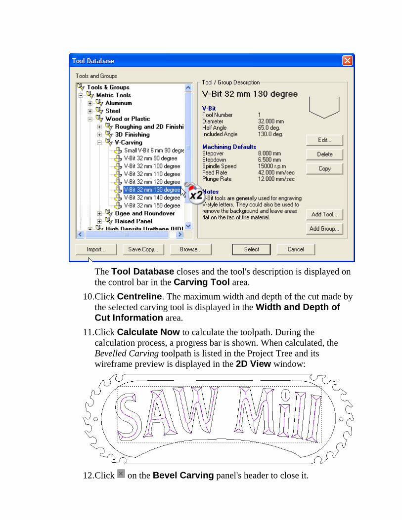
The Tool Database closes and the tool's description is displayed on
the control bar in the Carving Tool area.
10. Click Centreline. The maximum width and depth of the cut made by
the selected carving tool is displayed in the Width and Depth of Cut Information area.
11. Click Calculate Now to calculate the toolpath. During the
calculation process, a progress bar is shown. When calculated, the
Bevelled Carving toolpath is listed in the Project Tree and its
wireframe preview is displayed in the 2D View window:
12. Click on the Bevel Carving panel's header to close it.
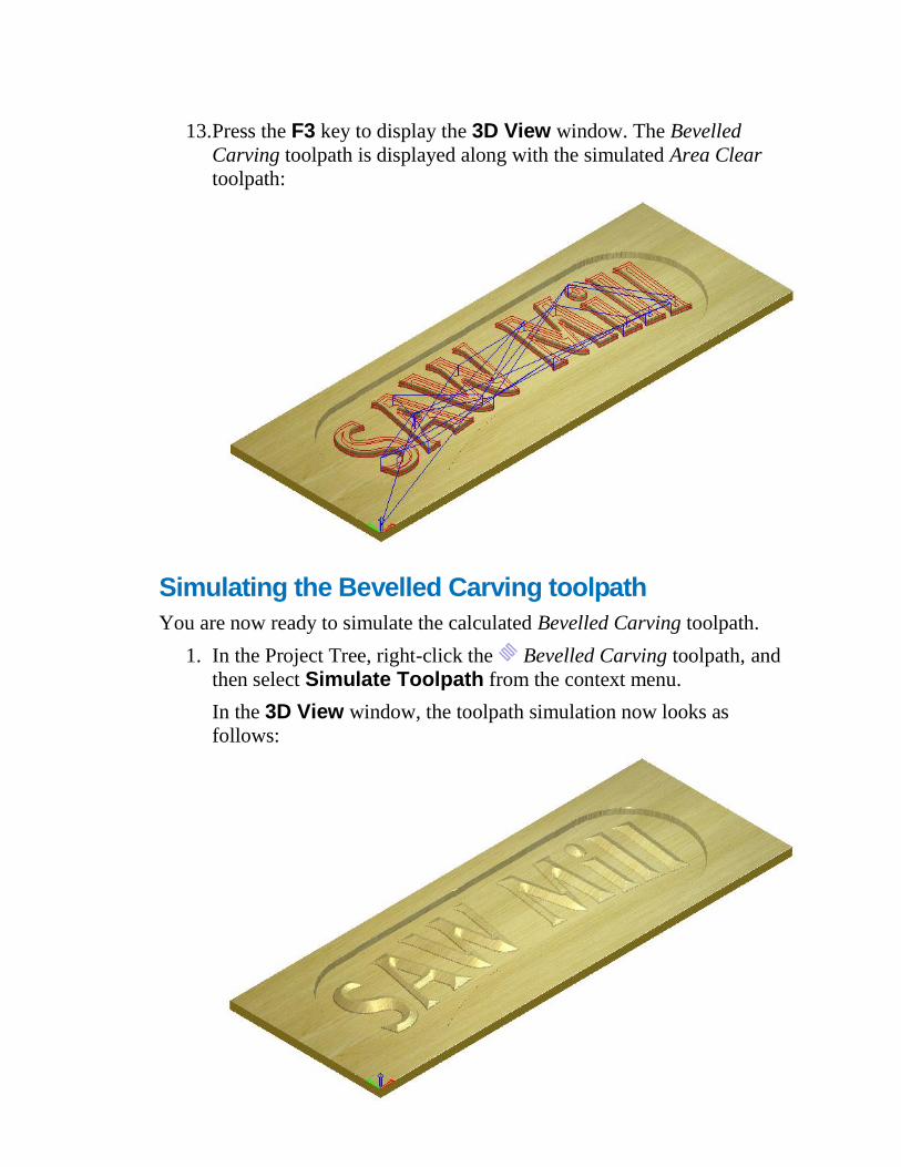
13. Press the F3 key to display the 3D View window. The Bevelled
Carving toolpath is displayed along with the simulated Area Clear
toolpath:
Simulating the Bevelled Carving toolpath
You are now ready to simulate the calculated Bevelled Carving toolpath.
1. In the Project Tree, right-click the Bevelled Carving toolpath, and
then select Simulate Toolpath from the context menu.
In the 3D View window, the toolpath simulation now looks as
follows:
Creating additional vector text
You are now ready to create some additional vector text. This will be used
when creating the third toolpath in the model.
1. Press the F2 key to display the 2D View window. The vector artwork
and the calculated Bevelled Carving toolpath's wireframe preview are
displayed.
2. From the Project panel, click to the right of Bevelled Carving
in the Project Tree. The wireframe toolpath preview is hidden in the
2D View window.
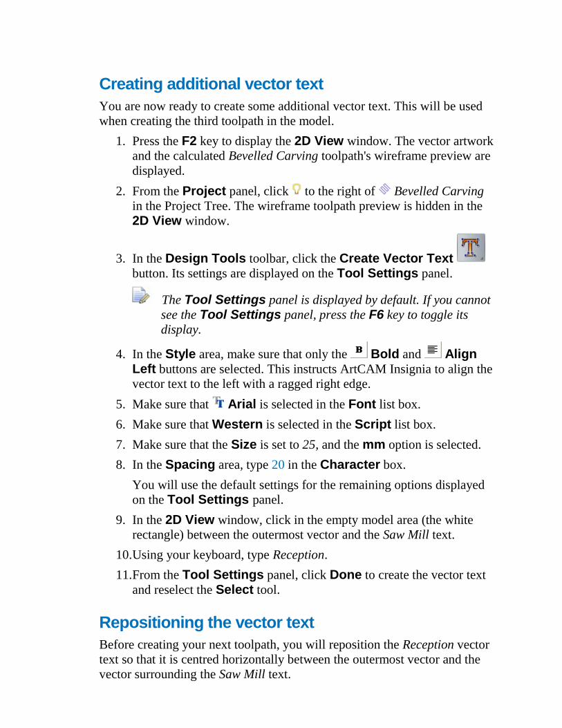
3. In the Design Tools toolbar, click the Create Vector Text
button. Its settings are displayed on the Tool Settings panel.
The Tool Settings panel is displayed by default. If you cannot
see the Tool Settings panel, press the F6 key to toggle its
display.
4. In the Style area, make sure that only the Bold and Align Left buttons are selected. This instructs ArtCAM Insignia to align the
vector text to the left with a ragged right edge.
5. Make sure that Arial is selected in the Font list box.
6. Make sure that Western is selected in the Script list box.
7. Make sure that the Size is set to 25, and the mm option is selected.
8. In the Spacing area, type 20 in the Character box.
You will use the default settings for the remaining options displayed
on the Tool Settings panel.
9. In the 2D View window, click in the empty model area (the white
rectangle) between the outermost vector and the Saw Mill text.
10. Using your keyboard, type Reception.
11. From the Tool Settings panel, click Done to create the vector text
and reselect the Select tool.
Repositioning the vector text
Before creating your next toolpath, you will reposition the Reception vector
text so that it is centred horizontally between the outermost vector and the
vector surrounding the Saw Mill text.
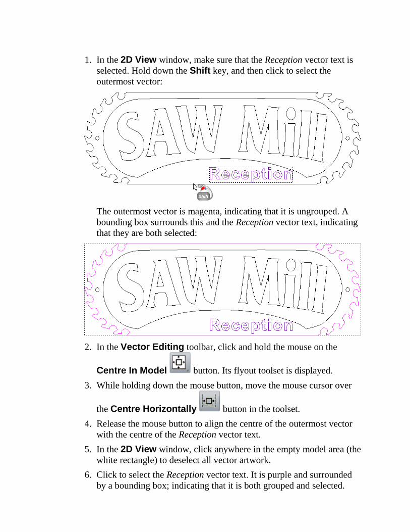
1. In the 2D View window, make sure that the Reception vector text is
selected. Hold down the Shift key, and then click to select the
outermost vector:
The outermost vector is magenta, indicating that it is ungrouped. A
bounding box surrounds this and the Reception vector text, indicating
that they are both selected:
2. In the Vector Editing toolbar, click and hold the mouse on the
Centre In Model button. Its flyout toolset is displayed.
3. While holding down the mouse button, move the mouse cursor over
the Centre Horizontally button in the toolset.
4. Release the mouse button to align the centre of the outermost vector
with the centre of the Reception vector text.
5. In the 2D View window, click anywhere in the empty model area (the
white rectangle) to deselect all vector artwork.
6. Click to select the Reception vector text. It is purple and surrounded
by a bounding box; indicating that it is both grouped and selected.
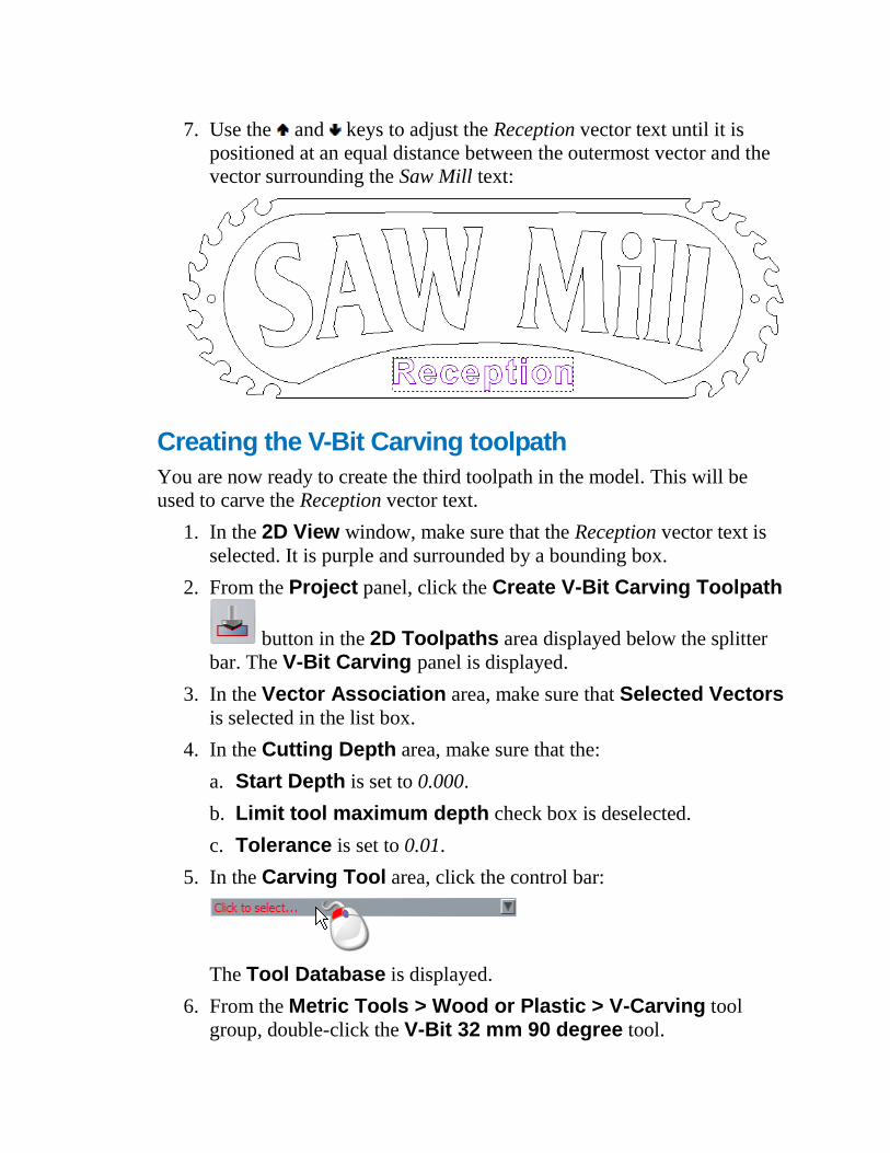
7. Use the and keys to adjust the Reception vector text until it is
positioned at an equal distance between the outermost vector and the
vector surrounding the Saw Mill text:
Creating the V-Bit Carving toolpath
You are now ready to create the third toolpath in the model. This will be
used to carve the Reception vector text.
1. In the 2D View window, make sure that the Reception vector text is
selected. It is purple and surrounded by a bounding box.
2. From the Project panel, click the Create V-Bit Carving Toolpath
button in the 2D Toolpaths area displayed below the splitter
bar. The V-Bit Carving panel is displayed.
3. In the Vector Association area, make sure that Selected Vectors
is selected in the list box.
4. In the Cutting Depth area, make sure that the:
a. Start Depth is set to 0.000.
b. Limit tool maximum depth check box is deselected.
c. Tolerance is set to 0.01.
5. In the Carving Tool area, click the control bar:
The Tool Database is displayed.
6. From the Metric Tools > Wood or Plastic > V-Carving tool
group, double-click the V-Bit 32 mm 90 degree tool.
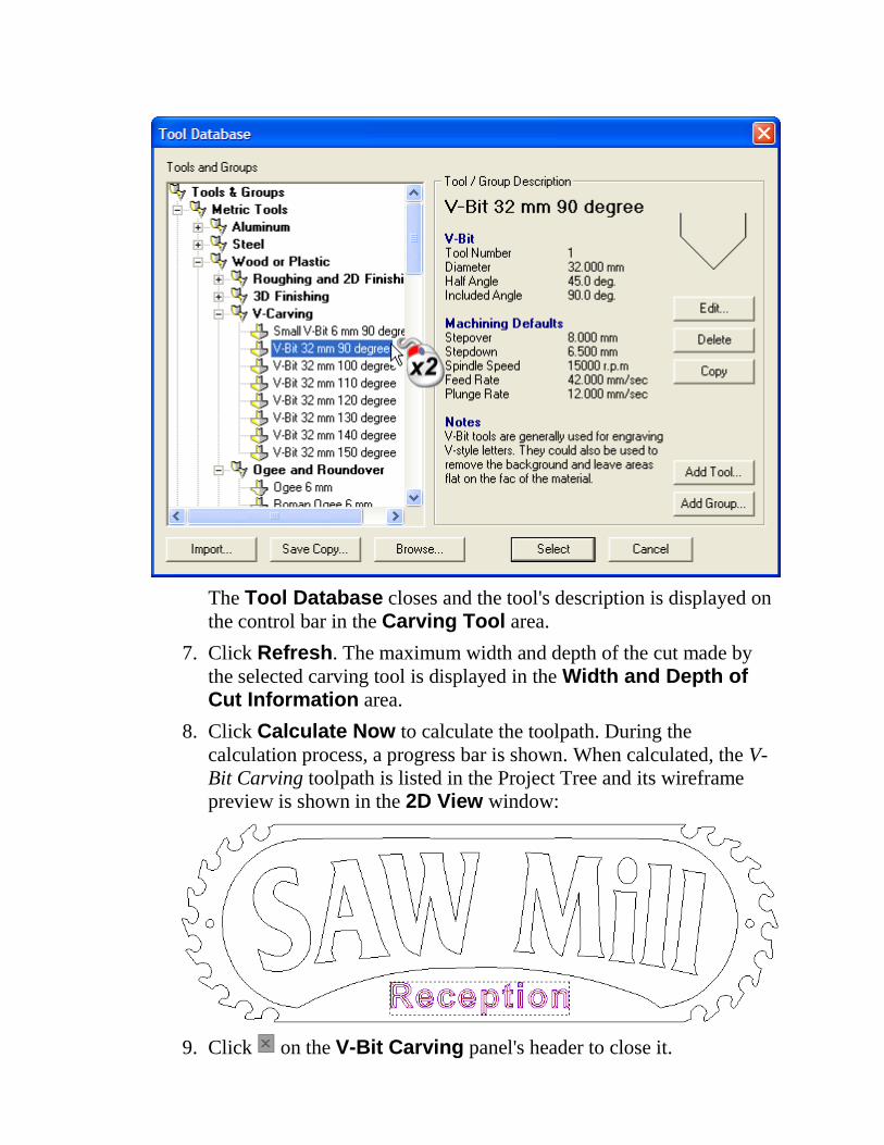
The Tool Database closes and the tool's description is displayed on
the control bar in the Carving Tool area.
7. Click Refresh. The maximum width and depth of the cut made by
the selected carving tool is displayed in the Width and Depth of Cut Information area.
8. Click Calculate Now to calculate the toolpath. During the
calculation process, a progress bar is shown. When calculated, the V-
Bit Carving toolpath is listed in the Project Tree and its wireframe
preview is shown in the 2D View window:
9. Click on the V-Bit Carving panel's header to close it.
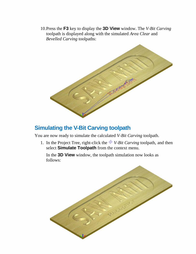
10. Press the F3 key to display the 3D View window. The V-Bit Carving
toolpath is displayed along with the simulated Area Clear and
Bevelled Carving toolpaths:
Simulating the V-Bit Carving toolpath
You are now ready to simulate the calculated V-Bit Carving toolpath.
1. In the Project Tree, right-click the V-Bit Carving toolpath, and then
select Simulate Toolpath from the context menu.
In the 3D View window, the toolpath simulation now looks as
follows:
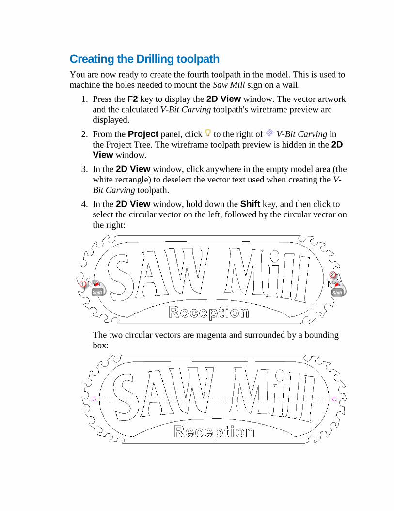
Creating the Drilling toolpath
You are now ready to create the fourth toolpath in the model. This is used to
machine the holes needed to mount the Saw Mill sign on a wall.
1. Press the F2 key to display the 2D View window. The vector artwork
and the calculated V-Bit Carving toolpath's wireframe preview are
displayed.
2. From the Project panel, click to the right of V-Bit Carving in
the Project Tree. The wireframe toolpath preview is hidden in the 2D View window.
3. In the 2D View window, click anywhere in the empty model area (the
white rectangle) to deselect the vector text used when creating the V-
Bit Carving toolpath.
4. In the 2D View window, hold down the Shift key, and then click to
select the circular vector on the left, followed by the circular vector on
the right:
The two circular vectors are magenta and surrounded by a bounding
box:
5. From the Project panel, click the Create Drilling Toolpath
button in the 2D Toolpaths area displayed below the splitter bar.
The Drilling panel is displayed.
6. In the Vector Association area, make sure that Selected Vectors
is selected in the list box.
7. In the Cutting Depth area, make sure that the:
a. Start Depth is set to 0.
b. Finish Depth is set to 12.
c. Plunge Clearance is set to 2.
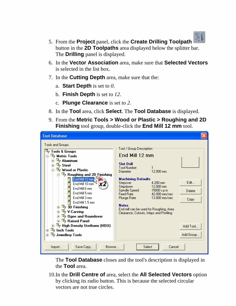
8. In the Tool area, click Select. The Tool Database is displayed.
9. From the Metric Tools > Wood or Plastic > Roughing and 2D Finishing tool group, double-click the End Mill 12 mm tool.
The Tool Database closes and the tool's description is displayed in
the Tool area.
10. In the Drill Centre of area, select the All Selected Vectors option
by clicking its radio button. This is because the selected circular
vectors are not true circles.
11. In the Drilling Strategy area, make sure that the Use Peck Drilling check box is deselected.
12. In the Sequencing area, make sure that:
a. the Auto option is selected.
b. Optimise is selected in the list box.
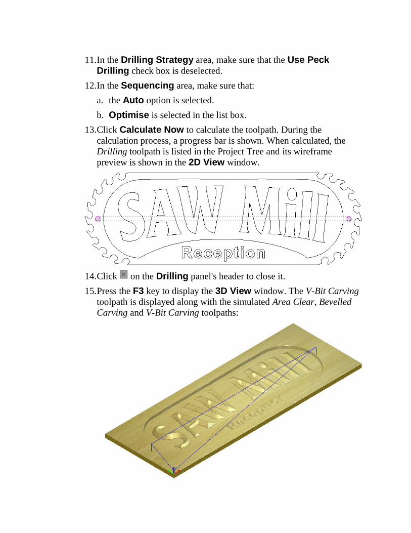
13. Click Calculate Now to calculate the toolpath. During the
calculation process, a progress bar is shown. When calculated, the
Drilling toolpath is listed in the Project Tree and its wireframe
preview is shown in the 2D View window.
14. Click on the Drilling panel's header to close it.
15. Press the F3 key to display the 3D View window. The V-Bit Carving
toolpath is displayed along with the simulated Area Clear, Bevelled
Carving and V-Bit Carving toolpaths:
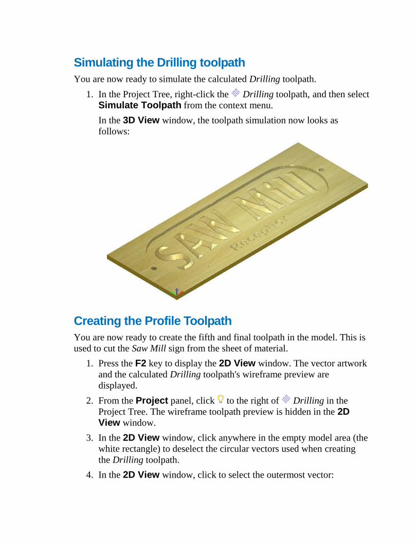
Simulating the Drilling toolpath
You are now ready to simulate the calculated Drilling toolpath.
1. In the Project Tree, right-click the Drilling toolpath, and then select
Simulate Toolpath from the context menu.
In the 3D View window, the toolpath simulation now looks as
follows:
Creating the Profile Toolpath
You are now ready to create the fifth and final toolpath in the model. This is
used to cut the Saw Mill sign from the sheet of material.
1. Press the F2 key to display the 2D View window. The vector artwork
and the calculated Drilling toolpath's wireframe preview are
displayed.
2. From the Project panel, click to the right of Drilling in the
Project Tree. The wireframe toolpath preview is hidden in the 2D View window.
3. In the 2D View window, click anywhere in the empty model area (the
white rectangle) to deselect the circular vectors used when creating
the Drilling toolpath.
4. In the 2D View window, click to select the outermost vector:
The vector is magenta and surrounded by a bounding box.
5. From the Project panel, click the Create Profile Toolpath
button in the 2D Toolpaths area displayed below the splitter bar.
The Profiling panel is displayed.
6. In the Profile Type & Vector Association area, make sure that:
a. Outside is selected in the Profile Type list box on the left.
b. Selected Vectors is selected in the Vector Association list
box on the right.
c. the Offset Allowance is set to 0.
d. the Final Pass Thickness and Final Pass Allowance check
boxes are deselected.
7. In the Cutting Depths area, make sure that the:
a. Start Depth is set to 0.
b. Finish Depth is set to 12.
c. Tolerance is set to 0.01.
8. In the Profiling Tool area, click the control bar:
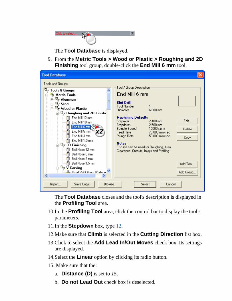
The Tool Database is displayed.
9. From the Metric Tools > Wood or Plastic > Roughing and 2D Finishing tool group, double-click the End Mill 6 mm tool.
The Tool Database closes and the tool's description is displayed in
the Profiling Tool area.
10. In the Profiling Tool area, click the control bar to display the tool's
parameters.
11. In the Stepdown box, type 12.
12. Make sure that Climb is selected in the Cutting Direction list box.
13. Click to select the Add Lead In/Out Moves check box. Its settings
are displayed.
14. Select the Linear option by clicking its radio button.
15. Make sure that the:
a. Distance (D) is set to 15.
b. Do not Lead Out check box is deselected.

c. Angle In is set to 45°
d. Angle Out is set to 45°
e. Over Cut (O) is set to 0.
f. Automatic Positioning check box is selected.
g. Add Ramping Moves check box is deselected.
16. Click Calculate Now to calculate the toolpath. During the
calculation process, a progress bar is shown. When calculated, the
Profile toolpath is listed in the Project Tree and its wireframe preview
is shown in the 2D View window.
At the top of the toolpath preview, you can see the circular arc lead.
With the Automatic Positioning check box selected when
calculating the Profile toolpath, ArtCAM Insignia positions the lead
move in the middle of the longest linear span. When deselected, the
position of the lead move is controlled by the position of the selected
vector's start node.
17. Click on the Profiling panel's header to close it.
18. Press the F3 key to display the 3D View window. The Profile
toolpath is displayed along with the simulated Area Clear, Bevelled
Carving, V-Bit Carving and Drilling toolpaths:
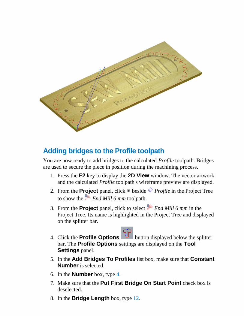
Adding bridges to the Profile toolpath
You are now ready to add bridges to the calculated Profile toolpath. Bridges
are used to secure the piece in position during the machining process.
1. Press the F2 key to display the 2D View window. The vector artwork
and the calculated Profile toolpath's wireframe preview are displayed.
2. From the Project panel, click beside Profile in the Project Tree
to show the End Mill 6 mm toolpath.
3. From the Project panel, click to select End Mill 6 mm in the
Project Tree. Its name is highlighted in the Project Tree and displayed
on the splitter bar.
4. Click the Profile Options button displayed below the splitter
bar. The Profile Options settings are displayed on the Tool Settings panel.
5. In the Add Bridges To Profiles list box, make sure that Constant Number is selected.
6. In the Number box, type 4.
7. Make sure that the Put First Bridge On Start Point check box is
deselected.
8. In the Bridge Length box, type 12.
9. In the Bridge Thickness box, type 1.
10. Make sure that the 3D Bridges check box is selected.
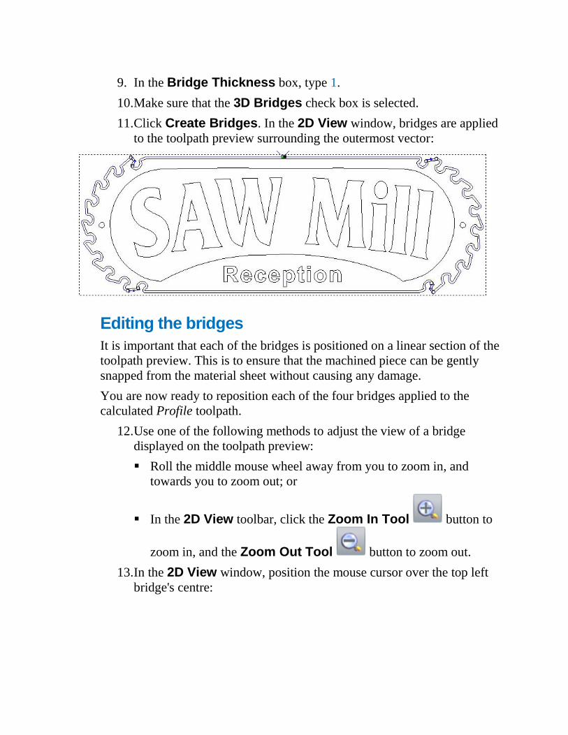
11. Click Create Bridges. In the 2D View window, bridges are applied
to the toolpath preview surrounding the outermost vector:
Editing the bridges
It is important that each of the bridges is positioned on a linear section of the
toolpath preview. This is to ensure that the machined piece can be gently
snapped from the material sheet without causing any damage.
You are now ready to reposition each of the four bridges applied to the
calculated Profile toolpath.
12. Use one of the following methods to adjust the view of a bridge
displayed on the toolpath preview:
Roll the middle mouse wheel away from you to zoom in, and
towards you to zoom out; or
In the 2D View toolbar, click the Zoom In Tool button to
zoom in, and the Zoom Out Tool button to zoom out.
13. In the 2D View window, position the mouse cursor over the top left
bridge's centre:
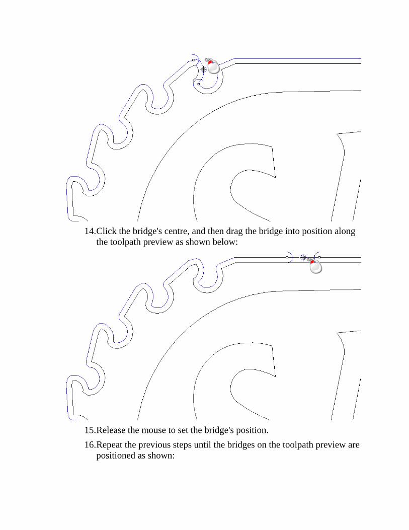
14. Click the bridge's centre, and then drag the bridge into position along
the toolpath preview as shown below:
15. Release the mouse to set the bridge's position.
16. Repeat the previous steps until the bridges on the toolpath preview are
positioned as shown:
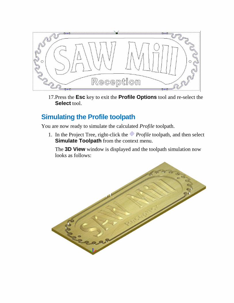
17. Press the Esc key to exit the Profile Options tool and re-select the
Select tool.
Simulating the Profile toolpath
You are now ready to simulate the calculated Profile toolpath.
1. In the Project Tree, right-click the Profile toolpath, and then select
Simulate Toolpath from the context menu.
The 3D View window is displayed and the toolpath simulation now
looks as follows:
Saving the toolpaths You are now ready to save the calculated toolpaths so that you can machine
the Saw Mill sign.
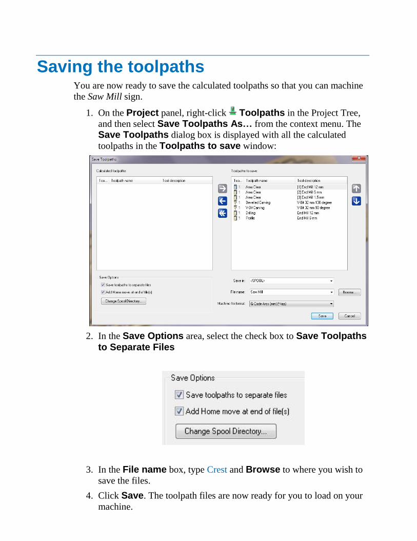
1. On the Project panel, right-click Toolpaths in the Project Tree,
and then select Save Toolpaths As… from the context menu. The
Save Toolpaths dialog box is displayed with all the calculated
toolpaths in the Toolpaths to save window:
2. In the Save Options area, select the check box to Save Toolpaths to Separate Files
3. In the File name box, type Crest and Browse to where you wish to
save the files.
4. Click Save. The toolpath files are now ready for you to load on your
machine.