Embed Size (px)
Citation preview

Sayfa / Page 1 www.orsanops.com
ISO 9001:2000 Kalite Yönetim Sistemi
Quality Management System

Sayfa / Page 2 www.orsanops.com
MODELLER : FOR STYLES :
4000 / 4000H
ÖNSÖZ FOREWORD Versiyon Değişim Tarihi: 06.09.2007 / R.00 Version Date: 06.09.2007 / R.00 Basım yeri İstanbul / Türkiye Printed in İstanbul / Turkey
Bu teknik el kitabı yeni Orsan OPS makinenizin bakımında size kılavuzluk etmesi için hazırlanmıştır. Bu makineleri çalıştırmak ve ayarlamak için dikkatle hazırlanmış bilgiler sizin tüm Orsan OPS makinelerinizin yüksek performansını ve güvenilirliğini sürdürmeyi olanaklı kılacak şekilde tasarlanıp geliştirilmiştir. Ayar tanımı ile ilgili bölüm, ilmiklere şekil veren her parçanın uygun şekilde kurulması ve makinenin fonksiyonlarını tamamlamasını ayrıntılı biçimde açıklamaktadır. Belirli parçaların kurulmasında yol göstermek amacıyla resimli şekiller kullanılmıştır. Mantıksal bir ilerleme sağlama açısından ayarlar ardarda sunulmuştur ki bazı ayarların diğer ilişik parçalarla karşıt sonuçlar doğurması söz konusu olmasın. Makinenize yeni parça yerleştirilmesi ve onarmanın gerekli olduğu hallerde Orsan OPS’nin ürettiği yedek parçaları kullandığınızdan emin olun ve bu hususta ısrarcı bir tutum sergileyin. Bu parçalar makineniz için özel olarak tasarlanmış olup elden geldiğince uzun süreli servisi garanti etmek için üretilmiştir. Her Orsan OPS makinesi, bu sınıftaki makineler üzerinde sağ ön tarafına iliştirilmiş stil plakası üzerine damgalanmış bir stil numarası ile tanımlanmıştır. Seri numarası makine tabanının sağ ön tarafında döküm yatağı içine damgalanmıştır.
This technical manual has been prepared to guide you in the maintenance of your new Orsan OPS machine. Careful attention to the instructions for operating and adjusting these machines will enable you to maintain the superior performance and reliability designed and built by every Orsan OPS machine. The portion of this manual consisting of adjusting instructions explains in detail the proper setting for each of the components related to forming the stitch and completing the functions of the machine. Figures are used to illustrate the adjustments using reference letters to point out specific items discussed. Adjustments are presented in sequence so that a logical progression is accomplished. Some adjustments performed out of sequence may have an adverse effect on the function of other related parts. Whenever it becomes necessary to make repairs or replace parts on your machine, be sure to insist on genuine Orsan OPS replacement parts. These parts are designed specifically for your machine and manufactured with the utmost precision to assure long lasting services. Each Orsan OPS machine is identified by a style number which, on this class machine, is stamped into the style plate affixed to the front right of the machine. The serial number is stamped into bed casting at the right front of the base of the machine.
Sayfa / Page 3 www.orsanops.com
İÇİNDEKİLER TABLE OF CONTENTS
PAGE / SAYFA GÜVENLİK KURALLARI………………………………………………………………………. 4 – 5 SAFETY RULES…………………………………………………………………………………. YEDEK PARÇA SİPARİŞİ VE………………………………………………………………….. 6 ORDERING REPAIR PARTS……………………………………………………………………. MAKİNE AÇIKLAMASI………………………………………………………………………… 6 STYLES OF MACHINE…………………………………………………………………………. SERVİSE KONULMASI VE İŞLETME………………………………………………………… 7 PUTTING INTO SERVICE AND OPERATION………………………………………………... YAĞLAMA ŞEMASI……………………………………………………………………………. 8 LUBRICATION DIAGRAM…………………………………………………………………….. BAKIM, YAĞLAMA VE ÇALIŞTIMA İÇİN HAZIRLIK…………………………………….... 9 MAINTENANCE, LUBRICATION AND PREPARING FOR OPERATION………………….. İĞNELER, İPLİKLEME VE ÇALIŞTIRMA…………………………………………………….. 10 NEEDLES, THREADING AND OPERATING…………………………………………………. İPLİKLEME ŞEMASI……………………………………………………………………………. 11 THREADING DIAGRAM……………………………………………………………………….. AYARLAMA TALİMATLARI………………………………………………………………….. 12 – 23 ADJUSTING INSTRUCTIONS………………………………………………………………….. BÜYÜTÜLMÜŞ GÖRÜNÜMLER VE PARÇALARIN TANIMLANMASI…………………… 24 – 45 EXPLODED VIEWS AND DESCRIPTION OF PARTS……………………………………….. PARÇALAR İÇİN NUMARALI FİHRİST………………………………………………………. 46 – 50 NUMERICAL INDEX OF PARTS……………………………………………………………….

Sayfa / Page 4 www.orsanops.com
GÜVENLİK KURALLARI 1- Bu kılavuzda anlatılan makineyi kullanıma almadan önce talimatları iyice okuyun. Her makinenin kullanıma başlamadan önce buradaki talimatlar iyice dikkate alınıp, sadece bu makineye kullanabilecek kalifiye elemanlar tarafından kullanılmalıdır. ÖNEMLİ! Makineyi kullanıma sokmadan önce ,motor imalatçısının da talimatlarını iyice okuyun. 2- Kendi ülkenizin ulusal güvenlik kurallarına uyunuz. 3- Bu kullanım kılavuzundaki belirtilen dikiş makinelerinin çalıştırılması , dikiş makinelerin konulduğu dikiş ünitesinin EC Makine şartnamesi 98/37/EC ,Ek 2B şartlarına uygun olduğunun tespit edildikten sonra yapılmalıdır. Her makine sadece öngörülen biçimde kullanılmalıdır. Bu belirlenen makinenin öngörülen kullanımı , bu kılavuzun ‘Makine açıklaması’ bölümünde anlatılmaktadır. Bir başka kullanım şekli , bu tanımların dışına çıkmak, öngörülen olarak kabul edilmemektedir. 4- Makineyi çalıştırmaya başlamadan önce veya çalışırken, tüm güvenlik cihazlarının olması gereken yerde olması gerekmektedir. İlgili güvenlik cihazları yerlerinde olmadan makineleri çalıştırma yasaktır. 5- Güvenlik gözlüğü takınız. 6-Makineye herhangi bir tadilat veya değişiklik yapıldığında , tüm güvenlik kurallarına uyulmalıdır. Tadilat veya değişikliklerin riski size aittir. 7- Talimatlardaki uyarı ip uçları bu iki sembolden biriyle belirtilmiştir.
8- Aşağıdakileri yapmadan önce makinenin güç kaynağının ana şalterden cereyanı kesilmelidir veya makinenin ana fişi çekilerek kesilmelidir. 8.1- Lüperlere , tırnaklara , iğneye vs. iplik geçirirken. 8.2- İğne , baskı ayağı , lüper, tırnak, dişli, iğne siperi, kumaş dayama vs. gibi parçaların değişiminde. 8.3- İş yerinden çıkarken veya iş yeri gözetimsizken. 8.4- Bakım yapılırken. 8.5- Hareketlendirme kilidi olan veya olmayan Debriyajlı motor kullanırken motorun tamamen durmasını bekleyin.
SAFETY RULES 1- Before putting the machine(s) described in this manual into service, carefully read all the instructions. The starting of each machine is only permissible after taking notice of all the instructions and when operated by qualified operators. IMPORTANT! Before putting the machine into service, also read the safety rules and instructions from the motor supplier. 2- Observe the national safety rules valid in your country. 3- The sewing machines described in this instruction manual are prohibited from being put into service until it has been ascertained that the sewing units which these sewing machines will be installed onto have conformed to the provisions of EC Machinery Directive 98/37/EC Annex II B.
Each machine is only allowed to be used as foreseen. The foreseen use of the particular machine is described in the paragraph “STYLES OF MACHINES” of this instruction manual. Any other use, going beyond the description, is not as foreseen. 4- All safety devices must be in position when the machine is ready for work or in operation. Operation of the machine without the appertaining safety devices is prohibited. 5- Wear safety glasses. 6- In case of machine conversions and changes all valid safety rules must be considered. Conversions and changes are made at your own risk. Orsan OPS does not assume responsibility if conversions are made. 7- The warning hints in the instructions are marked with either one of these two symbols.
8- When doing the following, the machine has to be disconnected from the power supply by turning off the main switch or by pulling out the main plug:
8.1- When threading needle(s), looper, spreader, etc. 8.2- When replacing any part(s) such as needle,
presser foot, throat plate, looper, spreader, feed dog, needle guard, folder, fabric guide, etc.
8.3- When leaving the workplace and when the work place is unattended.
8.4- When doing maintenance work. 8.5- When using clutch motors with or without
actuation lock. Make sure the motor is stopped completely.

Sayfa / Page 5 www.orsanops.com
9- Bakım, tamir ve tadilat (bkz. No:8) sadece eğitilmiş teknisyenler veya özel kalifiye personel tarafından , talimatlar doğrultusunda yapılmalıdır.
Tamirler yapılırken sadece ORSAN OPS tarafından üretilmiş yedek parçalar kullanılmalıdır. Bu parçalar makineniz için özel olarak tasarlanıp yüksek hassasiyette ve uzun ömürlü olarak üretilmiştir. 10- Her hangi bir elektrik ekipmanındaki çalışma bir elektrikçi veya özel kalifiye personel tarafından direkt veya denetlenerek yapılmalıdır. 11- Elektrik güç altında bulunan parçalar ve ekipmanlar üzerinde çalışmak yasaktır. İzin verilen istisnalar EN 50 110/VDE 0105 standart kağıdında bulunan ve belirlenen bölümde belirtilmektedir. 12- Pnömatik ekipmanlar üzerinde bakım ve tamir çalışması yapmadan önce, makine sıkıştırılmış hava ünitesinden bağlantıyı kesmeniz gerekir.Eğer arta kalan basınçlı hava kalmışsa (mesela hava tanklı pnömatik ekipman) bu basınç sızdırılarak çıkarılmalıdır. İstisnalar sadece özel kalifiye personel tarafından yapılan ayar işlemleri ve fonksiyonları için geçerlidir.
9- Maintenance, repair and conversion work (see item 8) must be done only by trained technicians or specially skilled personnel under consideration of the instructions. Genuine spare parts produced only by ORSAN OPS have to be used for repairs. These parts are designed specifically for your machine and manufactured with the utmost precision to assure a long life and long lasting service. 10- Any work on the electrical equipment must be done by an electrician or by specially qualified personnel directly or under supervision. 11- Work on parts and equipment while electrical power is on is not permitted. Permissible exceptions are stated in the applicable section found in the standard sheet EN 50 110/VDE 0105. 12- Before doing maintenance and repair work on the pneumatic equipment, the machine has to be disconnected from the compressed air supply unit. In case of residual pressurized air after disconnecting from the compressed air supply (e.g. pneumatic equipment with air tank), the air pressure has to be removed by bleeding. Exceptions are only allowed for adjustment and function checks done by specially skilled personnel.

Sayfa / Page 6 www.orsanops.com
YEDEK PARÇA SİPARİŞİ ORDERING REPAIR PARTS
Yedek parça siparişini kolaylaştırmak için mekanizmanın çeşitli parçalarının büyütülmüş görüntüleri gösterilmiştir ki parçaların makinedeki gerçek pozisyonları görülebilsin. Resimli sayfanın karşısındaki sayfada bu resimdeki parçaların parça numaraları, açıklamaları gereken parça adetleri listelenmiştir. İlk sütundaki numaralar sadece referans numaralarıdır ve sadece resimdeki parçanın pozisyonunu göstermektedir. Referans numaraları parçaların siparişinde asla kullanılmamalıdır. Daima ikinci sütundaki listelenmiş parça numaralarını kullanınız. Onarım için tedarik edilen alt parçalar, esas parçanın açıklamasının altında içe girintili olarak açıklamalarıyla yazılmıştır. Kataloğun arkasında bu katalogda gösterilen bütün parçaların numaralı indeksini bulacaksınız. Bu indeks sadece parça numaralarının bilindiği durumlarda açıklama ve resmin bulunmasını kolaylaştıracaktır. Önemli: Tüm siparişlerde lütfen sipariş ettiğiniz parçanın parça numarası, parça adını, istenilen miktarı ve makine cinsini belirtiniz.
MAKİNE AÇIKLAMASI 4000 ve 4000 H serisi makineler 2 iğneli 4
iplikli overlok+zincir dikiş makinesidir. Çift transportlu, manule yağlamalıdır.
Polipropilen ve jüt kumaşın kenarında 10mm.lik overlok dikiş yapabilen ve buna 5 mm. uzaklıkta ek zincir çift kilitli dikiş yapabilen çok ağır çuval kumaşı için üretilmiş makinedir. Dikiş özellikleri : İğne uzaklığı 5mm. Toplam dikiş genişliği 15mm. Dikiş alanı 6-13 mm Baskı ayağının altındaki kapasite 22mm`ye kadar İşleme bağlı hız dakika başına 1400 devir. Baskı ayağı ve üst dişli için hava gereksinimi: 6 – 6,5 Bar’dır ( 4000 H ) Hava tüketimi : 20 litre/ dakika Tavsiye edilen devirde kullanılan makinenin sesi yaklaşık 84 db (A) DIN 45635-48 / ISO 10 821 4000 H: 4000 serisinin aynısıdır , tek farkı baskı ayak sisteminin pnomatik oluşudur. Net ağırlık: 40 kg.
To simplify ordering repair parts, various sections of the mechanism are shown with exploded views so that the parts may be seen in their actual positions in the machine. On the page opposite the illustration, a listing of the parts with their part numbers, descriptions and the number of pieces required in the particular view are shown. Numbers in the first column are reference numbers only and merely show the position of that part in the illustration. Reference numbers should never be used for ordering parts. Always use the part number listed in the second column.
Component parts of sub-assemblies which can be supplied for repairs are indicated with a description by indentation under the description of the main sub-assembly. At the back of the catalog a numerical index of all parts shown in this catalog can be found. This will facilitate locating the illustration and description when only the part number is known. Important: On all orders, please include part number, part name, quantity required and style of machine for the part ordered.
STYLES OF MACHINE
Styles 4000 and 4000 H are two needle, four thread, double transport safety stitch machines with manual lubrication. For matched seaming of very heavy bag fabrics made of jute, burlap or woven polypropylene with a 10 mm(3/8 inch) wide overedge stitch on the fabric edge and in a distance of 5 mm (13 gauge) to this with an additional double locked stitch. Seam specifications: Needle distance: 5 mm (13 gauge) Seam width: overall 15 mm (19/32 inch) Stitch range: 6 to 13 mm (2 to 4 SPI) Capacity below the presser foot: up to 22 mm (7/8inch) Speed: up to 1400 stitches per minute depending on the operation. Working pressure for presser foot and upper feed dog lifter must be: 6 – 6,5 bar (for 4000 H) Air consumption: 20 Nl/min. Equivalent continuous A-weighted sound pressure level on work stations at recommended operating speed: 84 db (A) according to DIN 45638-48 / ISO 10 821 4000 H: Same as 4000, but pneumatically operated presser foot and upper feed dog lifter. Weight net: 40 kg.

Sayfa / Page 7 www.orsanops.com
DİKKAT ! - CAUTION ! SERVİSE KONULMASI PUTTING INTO SERVICE
Ana voltaj ve devir sayısı fabrikada belirtilen servis voltajı ve devir sayısıyla uyumlu olmalıdır. Kullanmaya başlamadan önce belirtilen servis voltajı ve devir syısını not edin.
Makinenin sağ, sol, ön, yada arkası gibi yön ve yerini bildiren talimatlar aksi belirtilmedikçe kullanıcının makinedeki pozisyonuna göre verilmiştir. Makineye sağ taraftan bakıldığı zaman çalışma sırasında kasnak saat yönünde döner.
DİKKAT Makineyi üretime almadan önce kasnağın dönüş yönünü kontrol ediniz. Aksi taktirde parça kırılması meydana gelebilir.
İŞLETME Sadece kalifiye personelin makineyi çalıştırmasına izin verilmelidir. Güvenlik gözlükleri takınız. Aşağıdakiler için ana düğme kapalı durumda olmalıdır:
- İpliği iğneden, lüperden, çatal lüperden vb. den geçirmek için,
- İğne, baskı ayağı, plaka, lüper, çatal lüper, dişli, iğne siperi, kumaş dayama vb. gibi dikiş aletlerini değiştirmek için,
- Çalışma yeri terkedilince ve boş olunca, - Bakım çalışması yapıldığı zaman.
Ana düğme açık olduğu zaman hareket halindeki
makine parçalarına dokunmayınız. Yaralanma tehlikesi olabilir. Bu aynı zamanda ayarlamalar için de geçerlidir.
Bütün güvenlik aletleri makine çalışmaya ve işe
hazır olduğu zaman yerlerinde olmalıdır. Dikiş ünitesi sadece tasarlanmış amaç için
kullanılmalıdır. Herhangi bir değişim söz konusu olduğunda uygun güvenliğin sağlanması gereklidir.
Before using the machine, note the specified service voltage and number of cycles. The main voltage and the number of cycles of the machine must match the specified factory service voltage and the number of cycles.
Instructions stating direction or location, such as right, left, front or rear of machine, are given relative to operator’s position at the machine unless otherwise noted. The pulley rotates clockwise in the operating direction when viewed from the right end of the machine.
CAUTION Before putting into service, check the direction of the rotation. Breakage may occur when the direction of the rotation is wrong.
OPERATION Only qualified persons should be allowed to start and operate the machine. Wear safety glasses. The main switch has to be turned-off for the following:
- For threading the needle, looper, spreader, etc.
- For replacing sewing tools such as the needle, presser foot, throat plate, looper, spreader, feed dog, needle guard, folder, fabric guide, etc.
- When the work place is unattended and when leaving the work place.
- For maintenance work.
Do not touch moving machine parts while the main switch is turned on. This applies also to adjustments. Danger of injury!
All safety devices must be in position when the machine is ready for work or in operation.
The sewing unit should only be used for the intended purpose. In case of any conversions made to the machine, all applicable safeguarding provisions must be considered.

Sayfa / Page 8 www.orsanops.com
YAĞLAMA NOKTALARI LUBRICATING POINTS
ŞEKİL 1 FIG. 1
DİKKAT Yağlamaya başlamadan önce motorun şalterini kapatınız. Motorun tamamiyle durmasını bekleyiniz.
CAUTION: Turn off main power switch before lubricating! When using clutch motors with or without actuation lock, wait until the motor has completely stopped.
Sayfa / Page 9 www.orsanops.com
BAKIM MAINTENANCE
Önemli : Elektrikli aletle ilgili herhangibir iş yetkili kişiler tarafından ve ana fiş çekildikten sonra yapılmalıdır. DIN 57 105, veya VDE 0105`e bağlı olarak oluşan izin verilen sapmalarda hareketli parçalar ve aletler üzerinde çalışmaya izin verilmez. Büyük çaplı bakım çalışmaları ve tamiratta ana fişi çekin. Pnömatik aletlerin bakım ve onarımından önce dikiş ünitesinin sıkıştırılmış hava kaynağıyla bağlantısını kesin. İstisnalar sadece ayarlamalar ve fonksiyon testlerinin yetkili personel tarafından yapıldığı durumlarda geçerlidir. Ayrıca çalıştırma ve ayarlama talimatlarındaki tüm güvenlik kurallarına uyulmasına dikkat edin.
YAĞLAMA ve ÇALIŞMAYA HAZIRLAMA 4000 sınıfındaki makinelerin yağlama şemasında gösterildiği gibi günde 2 kez sabah makineyi kullanmaya başlamadan önce ve öğleden sonra makineyi kullanmaya başlamadan önce yağlanıp temizlenmelidir (şekil 1). Yağ kabı besleme gösterisi dolu tutulup dakikada 2-3 damla besleme yapacak şekilde ayarlanmalıdır. Yağ kabı, yağ miktarı en fazla 2/3`e indiği zaman tekrar doldurulmalıdır.
Yağlama için “ POLY markanın DM2 ” modelini tavsiye etmekteyiz.
Makineyi ilk kez çalıştırmadan önce iğne mili siperi (E,şekil 1) ve görüş besleme yağlayıcısı (maki-ne aksesuarlarıyla birlikte gelen) vidalanmalıdır. Yağ kabı ayarlanmalıdır. Yağlama şemasında (şekil 1) gösterilen tüm yağlama noktaları yağlanmalıdır. Ayarlama için yağ kabını yarısına kadar yağla doldurun ve ölçme iğnesini yaklaşık olarak dakikada 2 damla yağ akana kadar biraz içeri çevirin (A, şekil 1). Bu görüş camından kontrol edilebilir (B, şekil 1). Ölçme iğnesini güvenli şekilde yerleştirmeyi kilit somunu ile sağlayın (C, şekil 1). ÖNEMLİ!
Important: Any work on the electrical equipment should be done by authorized persons only and with the main plug pulled out. Apart from the permissible deviations according to DIN 57 105 or VDE 0105, work on live parts and equipment is not permitted. For extensive maintenance work and for repairs, pull out the main plug. Disconnect the sewing unit from the compressed air supply before making maintenance work or repairs on pneumatic equipment. Exceptions are allowed only if the adjustments and function tests are done by authorized persons. Also observe all safety rules included in the operating and adjusting instructions.
LUBRICATION AND PREPARING FOR OPERATION
The machines of class 4000 have to be cleaned and lubricated twice a day on the lubricating points indicated on the oiling diagram (fig.1). This action should be done once in the morning and once in the afternoon before starting work. The sight feed oiler has to be kept full and should be adjusted so that it feeds two to three drops of oil per minute. The sight feed oiler has to be refilled so that it is never less than 1/3 full. For lubrication we recommend “Mobil Oil DTE Medium.” Before operating a new machine for the first time, the needle bar guard (E, Fig.1) and the sight feed oiler, which come along with the accessories of the machine, have to be screwed in. The sight feed oiler has to be adjusted. All lubricating points, indicated on the oiling diagram (Fig.1), have to be oiled. For adjusting, fill the sight feed oiler half-way with oil and turn the metering pin (A, Fig.1) a little bit out. Then turn it in until it starts flowing at a rate of approximately two drops of oil per minute. This can be checked on the sight glass (B. Fig.1). Secure the setting of the metering pin with lock nut (C, Fig.1). Fill the oiler. IMPORTANT! The oil flow has to be turned on again before operating the machine.
Makineyi çalıştırmadan önce yağ akışı tekrar sağlanmalıdır.

Sayfa / Page 10 www.orsanops.com
Yağ kabını doldurun. Yeni makinenin yağlama işlemini çalıştırdıktan 10 dakika sonra tekrarlayın! Makinenin çalışması bittiği zaman yağ akışı, yağ kabındaki yana yatırma manivelası (D, Şekil 1) ile durdurulabilir.
İĞNELER Her iğnenin bir çeşit ve büyüklük numarası vardır. Her çeşit numarası, sapın çeşidi, ucu, uzunluğu, oluğu, finişi ve diğer ayrıntıları belirtir. Metrik ebat numarası, iğne sapı üzerine damgalanmıştır ve en büyük bıçak çapınıı gösterir. Bu çap sap ve gözün arasında mm.nin yüzde biriyle ölçülmüştür. Toplam oalarak çeşit ve ebat numarası (metre, inç) bütün sembolü Orsan OPS şirketi tarafından paketlenip satılan tüm iğnelerin üstündeki etiketlerde gösterir. Sözü edilen makine için standart iğne UY 9853 GA 430/172 çeşidir. Aşağıda açıklamalar ve uygun ebatlar verilmiştir. Çeşit Numarası Açıklama ve Ebatlar UY 9853 GA Yataklı yuvarlak sap,
yuvarlandırılmış kare uç, tek oluk,noktalı,krom kaplamalı.
Boyutlar: 300/120, 400/156, 430/172
İğne siparişini hızlı ve doğru olarak doldur-mak için boş bir paket, örnek iğne ya da çeşit ve ebat numarası gönderilmelidir. Etiketteki açıklama-yı kullanın. Tam sipariş şöyle görülmelidir. “ UY 9853 GA 430/172 - 100 Adet ”
İPLİKLEME 4000 serisi makinler şekil 2 de gösterildiği gibi ipliklenir.
İğneye iplik takmak için kasnağı iğnenin en üst noktaya gelene kadar çalıştırma yönünde çevirin. Lüper ipliğini takmak için makine hareketli kapağını pimini ( Resim 2 A )yukarı kaldırarak açın.
İpliği taktıktan sonra tekrar kapatın. ÇALIŞTIRMA 1- Ana şalteri açın. 2- Kumaşı dikilmek üzere baskı ayağını kaldırmadan, iğnenin önüne ve kumaş dayamasına sağa mümkün olduğunca yanaştırın. 3- Motor pedalına basınca makine dikişi yapar siz kumaşı yönlendirin. 4- Motor pedalını serbest bırakınca makine durur. İpliği kesin ve kumaşı makineden çıkarın. Dikilecek kumaşı yönlendirirken el ile iğne arasında 100 mm. Civarı bir güvenlik aralığını koruyun.
Repeat the oiling of a new machine after 10 minutes of operation! When the machine is out of operation, the oil flow can be stopped by tilting lever (D, Fig.1) on the sight feed oiler.
NEEDLES Each needle has a number for both type and size. The type number denotes the kind of shank, point, length, groove, finish and other details. The metric size number, stamped on the needle shank, denotes the largest diameter of blade measured in hundreds of a millimeter. Collectively, type and size number (metric/inch) represent the complete symbol which is printed on the label of all needles packaged and sold by Orsan OPS Corporation. The standard needle for the machine covered is type UY 9853 GA 430/172. Below are the description and available sizes: Type No: Description and sizes UY 9853 GA Round shank with seat, rounded square
point, single groove, spotted, chromium plated.
Sizes: 300/120, 400/156, 430/172 To have needle orders promptly and accurately filled, an empty package, and a sample needle or the type and size number should be forwarded. Use description on the label. A complete order would read: “ UY 9853 GA 430/172 - 100 Pcs.”
THREADING 4000 series machines are threaded as shown in Fig.2. For threading the needle, turn the hand wheel in the operating direction until the needle is in the uppermost position. For looper threading, open the hinge plate by lifting locking bolt knob (A fig 2). Close the hinge plate again after threading. OPERATING 1- Switch on main power switch. 2- Without lifting the presser foot, place the fabric to be sewn as close as possible in front of the needle and to the right on the edge guide. 3- Depress the motor treadle. The machine sews, guiding the fabric to be sewn. 4- Release the motor treadle. The machine stops. Cut the thread chain at the trailing edge of the fabric. Keep a security distance of approximately 10 cm. between your hand and sewing needle when guiding the fabric to be sewn!
DİKKAT!
Dikilecek kumaşı hizalamak için baskı ayağını ve üst dişliyi kaldırmanın gerekli olduğu durumlarda , makinenin istemeden çalışmasını engellemek için ayak motor pedalı üzerinden çekilir.
CAUTION!
Remove your foot from the motor treadle to avoid inadvertently starting the machine in case it is necessary to lift the presser foot and upper feed dog for aligning the fabric to be sewn!

Sayfa / Page 11 www.orsanops.com
İPLİKLEME ŞEMASI THREADING DIAGRAM
ŞEKİL 2 FIG. 2
İpliklemeden önce ana düğmeyi kapatınız. Kavramalı motor kullanılıyorsa motorun tamamen durmasını bekleyiniz.
UYARI!
CAUTION!
Turn-off main switch before threading! When using clutch motors with or without actuation lock, wait until the motor has completely stopped!
Sayfa / Page 12 www.orsanops.com
ŞEKİL 3 - FIG. 3
ŞEKİL 4 - FIG. 4
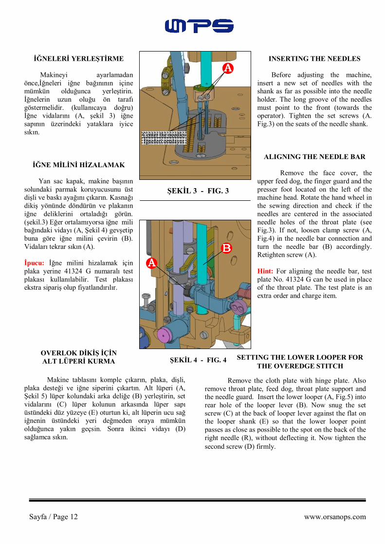
İĞNELERİ YERLEŞTİRME Makineyi ayarlamadan önce,İğneleri iğne bağınının içine mümkün olduğunca yerleştirin. İğnelerin uzun oluğu ön tarafı göstermelidir. (kullanıcaya doğru) İğne vidalarını (A, şekil 3) iğne sapının üzerindeki yataklara iyice sıkın.
İĞNE MİLİNİ HİZALAMAK Yan sac kapak, makine başının solundaki parmak koruyucusunu üst dişli ve baskı ayağını çıkarın. Kasnağı dikiş yönünde döndürün ve plakanın iğne deliklerini ortaladığı görün. (şekil.3) Eğer ortalamıyorsa iğne mili bağındaki vidayı (A, Şekil 4) gevşetip buna göre iğne milini çevirin (B). Vidaları tekrar sıkın (A). İpucu: İğne milini hizalamak için plaka yerine 41324 G numaralı test plakası kullanılabilir. Test plakası ekstra sipariş olup fiyatlandırılır.
OVERLOK DİKİŞ İÇİN ALT LÜPERİ KURMA
INSERTING THE NEEDLES Before adjusting the machine, insert a new set of needles with the shank as far as possible into the needle holder. The long groove of the needles must point to the front (towards the operator). Tighten the set screws (A. Fig.3) on the seats of the needle shank.
ALIGNING THE NEEDLE BAR Remove the face cover, the upper feed dog, the finger guard and the presser foot located on the left of the machine head. Rotate the hand wheel in the sewing direction and check if the needles are centered in the associated needle holes of the throat plate (see Fig.3). If not, loosen clamp screw (A, Fig.4) in the needle bar connection and turn the needle bar (B) accordingly. Retighten screw (A). Hint: For aligning the needle bar, test plate No. 41324 G can be used in place of the throat plate. The test plate is an extra order and charge item.
Makine tablasını komple çıkarın, plaka, dişli, plaka desteği ve iğne siperini çıkartın. Alt lüperi (A, Şekil 5) lüper kolundaki arka deliğe (B) yerleştirin, set vidalarını (C) lüper kolunun arkasında lüper sapı üstündeki düz yüzeye (E) oturtun ki, alt lüperin ucu sağ iğnenin üstündeki yeri değmeden oraya mümkün olduğunca yakın geçsin. Sonra ikinci vidayı (D) sağlamca sıkın.
SETTING THE LOWER LOOPER FOR THE OVEREDGE STITCH
Remove the cloth plate with hinge plate. Also remove throat plate, feed dog, throat plate support and the needle guard. Insert the lower looper (A, Fig.5) into rear hole of the looper lever (B). Now snug the set screw (C) at the back of looper lever against the flat on the looper shank (E) so that the lower looper point passes as close as possible to the spot on the back of the right needle (R), without deflecting it. Now tighten the second screw (D) firmly.
Center the needles İğneleri ortalayın
Sayfa / Page 13 www.orsanops.com
45
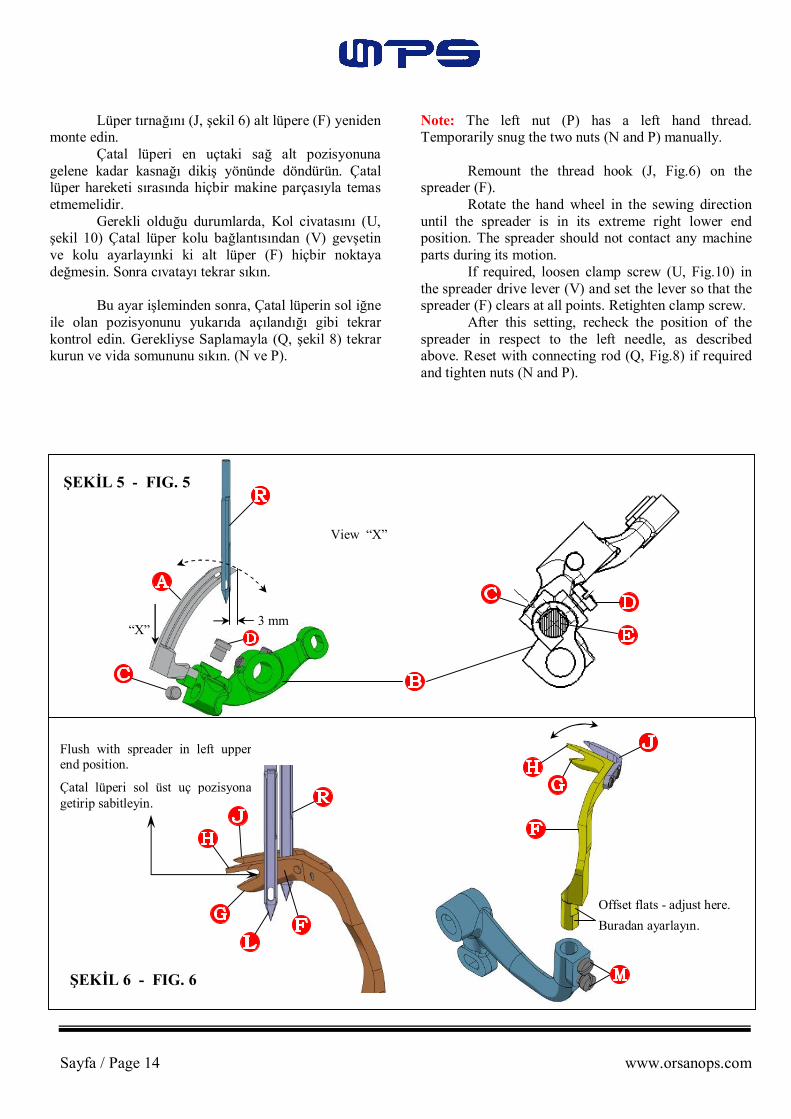
İĞNE MİLİ YÜKSEKLİĞİNİ AYARLAMAK Kasnağı dikiş yönünde alt lüperin ucu (A, Şekil 5) sağ iğnenin sağ tarafından sağa doğru 3 mm.çıkıntı oluşuncaya kadar döndürün. Lüperin aşağı ucu ve iğne gözünün üst ucu bu pozisyonda düz olmalıdır. Eğer ayarlama gerekliyse iğne mili bağı vidasını (A, Şekil 4) gevşetin ve iğne milini (B) gerektiği şekilde aşağı yukarı hareket ettirin. Bu ayarlamayı yaparken iğne barında yapılan hizalamaları bozulmaması için gereken özen gösterilmelidir. İğne mili bağı vidalarını sıkın.
OVERLOK İLMİKLERİ İÇİN SAĞ ÜST TIRNAK
BAĞINI YERLEŞTİRMEK Yeni çatal lüperi (F Şekil 6) koymadan önce Lüper tırnağını (J) çıkarın. Bu ayarlamanın gözle kontrolünü kolaylaştırır. Alt lüper (F Şekil 6 ve 7) ve iğnelerin (L ve R) ayarlanması için alt lüper sapının (F) iki tane düz taşlanmış yüzeyi var. İzlenecek Yol: Öncelikle bir vidayı (M, Şekil 6) alt lüper orta yerinin yüzeyine sıkıştırın. Bu şekilde alt lüper Şekil 6`daki pozisyonu sağlayacak. Kasnağı dikiş doğrultusunda döndürürken, alt lüper (F, Şekil 7) onun üst dişinin (H) ucundan 0,25-0,3 mm uzaklıkta sol iğnenin (L) akasından geçmelidir ve onun yüzü (K) sağ iğnenin (R) önüyle temas etmemelidir. Son olarak ikinci vidayı (M, Şekil 6) sıkıştırın. İpucu: Alt lüper sapının üzerindeki iki düz yüzey kullanılarak ayarlama yapılamazsa tüm alt lüper şaft yatağı (S, şekil 8), vidaları (R) gevşetirken hafifçe aşağı yukarı oynatılabilir. Vidaları yeniden sıkıştırın. Çatal lüperin en uç sol üst pozisyonunda (F, Şekil 6) çatal lüperin iç çukuru (G ve H) sol iğnenin (L) sol yanı ile hizaya gelmelidir. Ayarlama gerekliyse mafsal saplama somunlarını gevşetin (N ve P Şekil 8) ve (Q) gerekli pozisyonu elde etmek için ileri yada geri gerektiği şekilde ayarlayın.
SETTING HEIGHT OF NEEDLE BAR Rotate hand wheel in sewing direction until the point of lower looper (A, Fig. 5) projects 3 mm to the right from the right side of the right needle. The lower the edge of the looper and the upper edge of the needle eye must be flush in this position. If an adjustment is necessary, loosen clamp screw (A, Fig.4) in the needle bar connection and move the needle bar (B) up or down as required. Care should be taken not to disturb the alignment of the needle bar when making this adjustment. Retighten the clamp screw. SETTING THE RIGHT UPPER SPREADER FOR
THE OVEREDGE STITCH Before inserting a new spreader (F, Fig.6), remove the thread hook (J). This facilitates the visual check of the adjustment. For adjustment of the spreader (F, Figs. 6 and 7) with respect to the needles (L and R), the shank of the spreader (F) has two offset flats. Proceed as Follows: First, snug one screw (M, Fig.6) on the flat of the spreader shank which obtains the following position of the spreader. When rotating the hand wheel in the sewing direction, the spreader (F, Fig.7) should pass with the tip of its upper prong (H) at a distance of 0.25 to 0.3 mm behind the left needle (L) and its face (K) should not contact the front of the right needle (R). Now tighten the second screw (M, Fig.6) Hint: In case the adjustment of the spreader by means of the two offset flats on the spreader shank is not possible, the complete spreader shaft bearing (S, Fig.8) can be moved slightly up or down when loosening screws (R). Retighten screws. In the extreme left upper end position of the spreader (F, Fig.6), the bottom of the cut-out between the two spreader prongs (G and H) should be flush with the left side of the left needle (L). If an adjustment is necessary, loosen nuts (N and P, Fig. 8) and turn connecting rod (Q) forward or backward as required to obtain the required position. 1
Sayfa / Page 14 www.orsanops.com
Lüper tırnağını (J, şekil 6) alt lüpere (F) yeniden monte edin. Çatal lüperi en uçtaki sağ alt pozisyonuna gelene kadar kasnağı dikiş yönünde döndürün. Çatal lüper hareketi sırasında hiçbir makine parçasıyla temas etmemelidir. Gerekli olduğu durumlarda, Kol civatasını (U, şekil 10) Çatal lüper kolu bağlantısından (V) gevşetin ve kolu ayarlayınki ki alt lüper (F) hiçbir noktaya değmesin. Sonra cıvatayı tekrar sıkın. Bu ayar işleminden sonra, Çatal lüperin sol iğne ile olan pozisyonunu yukarıda açılandığı gibi tekrar kontrol edin. Gerekliyse Saplamayla (Q, şekil 8) tekrar kurun ve vida somununu sıkın. (N ve P).
Note: The left nut (P) has a left hand thread. Temporarily snug the two nuts (N and P) manually. Remount the thread hook (J, Fig.6) on the spreader (F). Rotate the hand wheel in the sewing direction until the spreader is in its extreme right lower end position. The spreader should not contact any machine parts during its motion. If required, loosen clamp screw (U, Fig.10) in the spreader drive lever (V) and set the lever so that the spreader (F) clears at all points. Retighten clamp screw. After this setting, recheck the position of the spreader in respect to the left needle, as described above. Reset with connecting rod (Q, Fig.8) if required and tighten nuts (N and P).
“X”
View “X”
3 mm
Offset flats - adjust here.
Buradan ayarlayın.
Flush with spreader in left upper end position.
Çatal lüperi sol üst uç pozisyona getirip sabitleyin.
ŞEKİL 5 - FIG. 5
ŞEKİL 6 - FIG. 6

Sayfa / Page 15 www.orsanops.com
Kasnağı dikiş yönünde döndürün.Çatal lüper yukarı doğru yol alırken (F, şekil 9) çatal (G) ucu, alt lüperin (A) gözünü arkasındaki girintiye temas etmeden olabildiğince yakın geçmelidir. Eğer ayarlama gerekirse, Lüper kolunun üzerindeki vida somununu (T, şekil 8) ve alt lüper kolunu, alt lüper ile sağa sola gereğince ayarlayın. Vida somununu (T) tekrar sıkın. Uyarı: Bu ayarlamayı yaptıktan sonra iğne mili yüksekliğinin ayarını kontrol edin ve gerekliyse yeniden ayarlayın. “İĞNE MİLİNİN YÜKSEKLİĞİNİN KURULMASI” başlıklı paragrafa gidin.
Rotate hand wheel in the sewing direction. On the upward travel of the spreader (F, Fig.9), the tip of its lower prong (G) must pass as close as possible in the recess behind the eye of the lower looper (A) without contacting it. If an adjustment is required, loosen nut (T, Fig.8) on the double joint and the lower looper lever with lower looper as necessary to the right or left. Retighten nut (T). Caution: Check the setting of the needle bar height after making this adjustment and reset if required. Refer to paragraph “SETTING HEIGHT OF NEEDLE BAR”.
ŞEKİL 7 - FIG. 7 ŞEKİL 8 - FIG. 8
ŞEKİL 10 - FIG. 10 ŞEKİL 9 - FIG. 9
0,25mm-0,3mm

Sayfa / Page 16 www.orsanops.com
OVERLOK İLMİK İÇİN İPLİK TIRNAĞININ KURULMASI
Makinenin sol tarafından bakıldığı zaman, iplik tırnağı (B, şekil 11) yukarı doğru hareket ederken alt lüperin sol yanından (A), temas etmeden olabildiğince yakın geçmelidir. Sallanma hareketinin en üst noktasında, iplik alt lüperin (B) plakanın altına veya dişliye mani olmamalıdır. Vidayı gevşettikten sonra (C, şekil 11) Tırnak (B) sağa veya sola hareket ettirilebilir. Vidayı tırnak sapının düz tarafına tekrar sıkın. Sabit iki vidayı (D) gevşettikten sonra, mil (E) iplik tutucuyla (B) döndürülerek doğru pozisyona getirilebilir. Sabit vidaları sıkarken, tırnağın boşluğunu alın.
ZİNCİR LÜPERİNİ TAKMAK Zincir lüperini (A, şekil 12) yerleştirin ve vida (B) ile sapının düz yüzeyine sıkın ki olabildiğince sol iğnenin arkasından, ona temas etmeden yakın geçsin. Şimdi sabit vidaları (C) sıkın.
SETTING THE THREAD RETAINER FOR THE OVEREDGE STITCH
Viewed from the left end of the machine, the thread retainer (B, Fig.11) should pass as close as possible on the left side of lower looper (A) when swinging upward without contacting it. On the most upward position of its swing motion, the thread retainer (B) should not interfere either with the bottom of the throat plate or with the feed dog. After loosening the screw (C, Fig.11), the thread retainer (B) can be moved to the right. Retighten the screw on the flat of the thread retainer shank. After loosening the two set screws (D), the shaft (E) with the thread retainer (B) can be rotated into the correct position. Make sure to remove all lateral end play when tightening the set screws.
SETTING THE DOUBLE LOCKED STITCH LOOPER
Insert the double locked stitch looper (A, Fig.12) and tighten it with screw (B) on the flat of its shank so that it passes as close as possible behind the left needle without touching it. Now tighten set screws (C).
ŞEKİL 11 - FIG. 11 ŞEKİL 12 - FIG. 12

Sayfa / Page 17 www.orsanops.com
KANCAYI ZİNCİR DİKİŞ İÇİN YERLEŞTİRMEK
Çekici lüperi hareket ettiren iki küre yatağının, merkezinden diğer merkeze olan uzaklığı (Standart uzaklık) 51 mm. olmalıdır (şekil 13). Temel olarak, küre yatağının önü (H, şekil 13), çekici lüper kolu (J) bağlantı deliğinin,mümkün olduğunca soluna bağlanmalıdır.
SETTING THE CROSS LOOPER FOR DOUBLE LOCKED STITCH
The distance (set at the factory) from center to center of the two ball joints driving the cross looper should be 51mm (2 in.) (See Fig.13). Basically, the front ball joint (H, Fig.13) should be positioned as far as it will go to the left in the fastening slot of the cross looper drive lever (J).
ŞEKİL 13 - FIG. 13
Kasnağı dikiş yönünde döndürürken, kanca (D, şekil 14) zincir lüperinin (A) üzerin-den, arkasındaki girintiye temas etmeden olabildiğince yakın geçmelidir. Soldaki sallanma hareketinde, kanca, (D, şekil 15) sol iğnenin (L), çekici lüper (D) kancasından asılı olan iplik ilmiği içinden, güvenli şekilde geçerek dikiş yapmasını sağlayacak şekilde yerleştirilmelidir. Çekici lüper sol iğnenin önünden 0,3mm uzaklıktan geçmelidir. (şekil 15).
When rotating the hand wheel in the sewing direction, the cross looper (D, Fig.14) should swing as close as possible in the recess behind the eye over the double locked stitch looper (A) without contacting it. At the left end of its swing motion, the cross looper (D, Fig.15) must be positioned so that the left needle (L) securely stitches into the thread loop hanging around the hook of cross looper (D). In front of the left needle, the cross looper should pass at a distance of 0.3mm (0.012in.) (See Fig.15).
51mm
Bu Şekilde Kontrol Edin: Kancanın etrafına, bir parça iplik sarın ve hafifçe dikiş yönünde çekin. Şimdi kasnağın dikiş yönünde döndürün, sol iğne güvenli bir şekilde iki iplik arasına girmelidir.
İki vidayı (E, Resim 15) gevşettikten sonra, sol iğneye olan 0,3mm`lik uzaklık ayarlanabilir. Vidaları, kancanın sapındaki düz taşlanmış yüzeye tekrar sıkın. Cıvatayı (G, Resim 14) gevşettikten sonra, kanca kolunu (F) kancanın (D) yüksekliğini ayarlamak için zincir lüperine (A) göre alçaltılıp yükseltilebilir ve kanca kolu, kancanın sallanma hareketini, sol iğneye göre ayarlamak için sağa sola yatırılabilir. Cıvatayı tekrar sıkın. Eğer istenirse, kanca sallanma hareketinin yol uzunluğu, küre yatağını (H, şekil 13) kanca kolu (J) bağlantı yuvasının sağına yerleştirerek azaltılabilir. Kancayı takarken, onun plakanın altını ya da başka bir makine parçasını engellemediğinden emin olun.
Check As Follows: Wind a piece of thread around the hook of the cross looper and draw it lightly in the sewing direction. Now rotate the hand wheel in the sewing direction. The left needle must enter securely between the two thread ends. After loosening the two screws (E, Fig.15), the 0.3mm (.012 in.) distance from the end of the cross looper to the left needle is adjustable. Retighten screws on the flat of the cross looper shank. After loosening clamp screw (G, Fig. 14), the cross looper lever (F) can be raised or lowered for setting the height of the cross looper (D) with respect to the double locked stitch looper (A), and it can be tilted to the right or left for adjusting the swing motion of the cross with respect to the left needle. Retighten the clamp screw. When required, the length of the path of the cross looper swing motion can be reduced by positioning the ball joint (H, Fig.13) to the right in the fastening slot of the cross looper drive lever (J). When setting the cross looper, make sure that it does not interfere with the bottom of the throat plate or other machine parts.

Sayfa / Page 18 www.orsanops.com
ŞEKİL 15 - FIG. 15 ŞEKİL 14 - FIG. 14
İĞNE SİPERİNİ TAKMAK İğne koruyucusu (A, Şekil 16) en ileri po-zisyonuna geldiği zaman, koruyucu yüzeyleri, iğneleri saptırmadan onların hemen arkalarına temas etmelidir. Vidayı (B, Şekil 16) gevşettikten sonra, iğne koruyucu (A) öne ve arkaya doğru hareket ettirilebilir. Vidayı yeniden sıkın. Not: İlmik uzunluğundaki herhangi bir değişiklik, iğne koruyucu yerleştirilmesine tekabül eden bir değişikliği gerekli kılar.
0.3mm
SETTING THE NEEDLE GUARD When the needle guard (A, Fig.16) is in its most forward end position, its guarding surface should just contact the back of the needles without deflecting them. After loosening the screw (8, Fig.16), the needle guard (A) can be moved accordingly to the front or rear. Retighten screw. Note: Any change in stitch length necessitates a corresponding change in the needle guard setting.
ŞEKİL 16 - FIG. 16 ŞEKİL 17 - FIG. 17
Sayfa / Page 19 www.orsanops.com
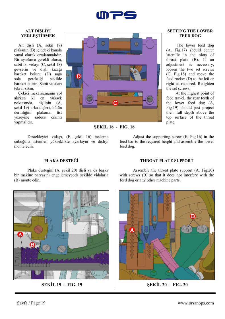
SETTING THE LOWER FEED DOG
The lower feed dog (A, Fig.17) should center laterally in the slots of throat plate (B). If an adjustment is necessary, loosen the two set screws (C, Fig.18) and move the feed rocker (D) to the left or right as required. Retighten the set screws. At the highest point of feed travel, the rear teeth of the lower feed dog (A, Fig.19) should just project their full depth above the top surface of the throat plate.
ALT DİŞLİYİ YERLEŞTİRMEK
Alt dişli (A, şekil 17) plakanın (B) içindeki kanala yanal olarak ortalanmalıdır. Bir ayarlama gerekli olursa, sabit iki vidayı (C, şekil 18) gevşetin ve dişli kızağı hareket kolunu (D) sağa sola gerektiği şekilde hareket ettirin. Sabit vidaları tekrar sıkın. Çekici mekanizmanın yol alırken ki en yüksek noktasında, dişlinin (A, şekil 19) arka dişleri, bütün derinliğini plakanın üst yüzeyine sadece çıkıntı yapmalıdır.
ŞEKİL 18 - FIG. 18
Destekleyici vidayı, (E, şekil 16) besleme çubuğuna istenilen yükseklikte ayarlayın ve dişliyi monte edin.
PLAKA DESTEĞİ Plaka desteğini (A, şekil 20) dişli ya da başka bir makine parçasını engellemeyecek şekilde vidalarla (B) monte edin.
Adjust the supporting screw (E, Fig.16) in the feed bar to the required height and assemble the lower feed dog.
THROAT PLATE SUPPORT Assemble the throat plate support (A, Fig.20) with screws (B) so that it does not interfere with the feed dog or any other machine parts.
ŞEKİL 19 - FIG. 19 ŞEKİL 20 - FIG. 20

Sayfa / Page 20 www.orsanops.com
ÜST DİŞLİYİ YERLEŞTİRME
Üst dişliyi (B, şekil 21) ve baskı ayağını (C) monte edin.Üst dişli, (B) baskı ayağı (C) kanallarında hareket ederken, ön ya da arka uçları itmemeli. Eş zamanda, üst dişli (B, şekil 19) dişlerinin ucu, alt dişlinin (A) diş boşluklarına temas etmeyecek şekilde girecek konuma geti-rilmelidir. Alt dişli (A) en yukarı ve üst dişli (B) en aşağı hareketindeyken, her iki dişli arasında küçük bir boşluk olma-lıdır.
ŞEKİL 21 - FIG. 21
ŞEKİL 23 - FIG. 23 ŞEKİL 22 - FIG. 22
Üst ve alt dişlinin besleme hareketi eş zamanlı olmalıdır. Üst dişliyi baskı ayağında biten oluğa ve alt dişlinin diş boşluklarına bağlı olarak yerleştirmek için, vidayı (D, şekil 21) gevşetin ve sürüş kolunu (E) uygun şekilde öne yada arkaya çevirin. Vidayı tekrar sıkın.
The feed travel of the upper and lower feed dog should be synchronous. For setting the upper feed dog with respect to the slot ends in the presser foot and the tooth spaces of the lower feed dog, loosen screw (D, Fig.21) and move drive lever (E) accordingly to the front or rear. Retighten screw.
SETTING THE UPPER FEED DOG
Assemble the upper feed dog (B, Fig.21) and the presser foot (C). The upper feed dog (B) should not push against the front or rear end when moving in the slots of the presser foot (C). Simultaneously the upper feed dog (B, Fig.19) should be positioned so that the tips of its teeth engage with the tooth spaces of the lower feed dog (A, Fig. 19), without contacting it. When the lower feed dog (A) is in its highest and the upper feed dog (B) in its lowest point of travel, there must be a small gap between both feed dogs.

Sayfa / Page 21 www.orsanops.com
Dişlilerin arasındaki küçük aralığı ayarlamak için vida somununu (F, şekil 22) gevşetin. Vidayı (G) içe döndürmek, aralığı arttırır, dışa döndürmek azaltır. Vida somununu (F) tekrar sıkın. Üst dişlinin hareketini, alt dişli ile uyumlu hale getirmek için vidayı (A, şekil 23) gevşetin. Ayar kolunun (B), oluğundaki küre bağlantısının öne hareketi üst dişlinin hareketini azaltır, arkaya hareketi ise hareketi arttırır. Vidayı (A) tekrar sıkın.
ÜST DİŞLİNİN KALDIRMA HAREKETİNİ AYARLAMAK
Dönüş hareketinde, üst dişli olabildiğince yukarı kalkmalıdır ki hiçbir kumaş yönüne karşı çekilmemelidir. Hareket ayarlanmalıdır ki, üst dişlinin arka dişlisinin (B, şekil 21) baskı ayağı kanallarına olan yükseklikleri, kaldırma esnasında yaklaşık olarak 1/3 oranında kalsın. Ayarlama için iki vidayı (H, şekil 22) gevşetin ve üst dişlinin daha fazla kalkması gerektiği zaman bağlantı parçasını (J) yükseltin, daha az kalkması gerektiğinde ise alçaltın. Vidaları (H) tekrar sıkın.
For setting the small gap between the feed dogs, loosen nut (F, Fig.22). Turning in the screw (G) increases the gap and turning it out decreases the gap. Retighten nut (F). For matching the upper feed dog travel with the lower feed dog travel loosen screw (A, Fig.23). Moving the ball link in the slot of the rocker lever (B) to the front decreases the upper feed dog travel and moving it to the rear increases the travel. Retighten screw (A).
SETTING THE LIFT MOTION OF THE UPPER FEED DOG
On the return travel, the upper feed dog should lift high enough so that no fabric will be pulled against the sewing direction. The motion should be set so that the rear four teeth of the upper feed dog (B, Fig.21) remain approximately 1/3 of their height in the presser foot slots when lifting. For adjustment, loosen the two screws (H, Fig.22) and raise the supporting yoke (J) when the upper feed dog should lift more, or lower it when it should lift less. Retighten screws (H).
ŞEKİL 24 - FIG. 24 ŞEKİL 25 - FIG. 25

Sayfa / Page 22 www.orsanops.com
BASKI AYAĞI BASINCI Kasnağı, alt dişli, plakanın altına gelene kadar döndürün. Baskı somununu (A, şekil 24) gevşetin ve T vidasını (B) yaprak yaylara basınç uygulamayana kadar kadar açın. Bu pozisyonda, baskı ayağına uygulanan basınç öyle güçlü olmalıdır ki, baskı ayağı altı ve baskı ayağı dilinin ön ucu tam olarak rahat bir şekilde plaka üzerinde dursun. Sol ve sağ baskı milinde, yaprak yaylarının oturağı olarak kullanılan bilezikleri (C, şekil 25) yeniden ayarlayarak basınç değişebilir. Bilezikleri yükseltmek basıncı arttırır, alçaltmak ise azaltır. Baskı ayağı yükselme derecesi, sağ baskı milinin üzerindeki üst durdurma bileziği (D, şekil 25) ile sınırlandırılmıştır. İğneler en alt seviyesindeyken ve baskı ayağı, baskı ayak kaldırma kolu ile kalkmış durumdayken, iğne bağı baskı ayağı ile temas etmemelidir. Bunun yanında, kalkmış olan baskı ayağı, sağ üst alt lüper yukarıya doğru hareket ederken, ona temas etmemelidir. Buna göre dur-durma bileziğini (D) ayarlayın. Her iki baskı milinin de yukarı aşağı birbirine yapışmadan hareket ettiğinden emin olun. Şimdi T vidasını (B, şekil 24) gerekli baskı ayağı basıncı, doğru besleme uygulayana kadar açın. (Dikiş testleriyle karar verin) baskı somunu (A) ile ayarlamayı sağlayın. Eş zamanlı olarak bu ayarlama üst kol koruyucusunu da tutturur. Yüz koruyucunu ve parmak koruyucusunu yeniden monte edin.
KUMAŞ DAYAMA VE KUMAŞ DAYAMA DİLİ
Kumaş dayama (A, şekil 26) baskı ayağına temas etmeden, olabildiğince yakına, yanal olarak kurun. İki vidayı (B) gevşetirken kumaş dayama (A) yanal olarak kurun. İki vidayı (B) gevşetirken kumaş dayama rehberi (A) yanal olarak hareket ettirilebilir. Vidaları tekrar sıkın. Kumaş dayama dilini (C, şekil 26) öyle kurun ki; iplik lüperinin arka tarafı, dil üzerinden, sağ iğne ilmiğe güvenli bir şekilde girene kadar ilmiğin ön tarafı tutulurken, kumaşın üzerine kaysın. Vidaları gevşettikten sonra, kumaş dayama dili (C) öne ve arkaya hareket ettirilebilir. Kumaş dayama dili arkaya hareket ettirilirken, iplik ilmiğinin ön kısmı daha uzun süreli, tutulu kalır. vidaları (D) tekrar sıkın. Hareket ederken, alt lüper (E, şekil 26) kumaş dayama dili (C) ile temas etmemelidir.
PRESSER FOOT PRESSURE Rotate the hand wheel until the lower feed dog is below the throat plate. Loosen the knurled nut (A, Fig. 24) and turn out the T-screw (B) until it does not exert any pressure on the leaf springs. In this position, the pressure exerted on the presser foot should be so strong that the presser foot bottom and the front end of the presser foot tongue rest squarely on the throat plate. By relocating the collars (C, Fig. 25) which serve as a leaf spring rest, on the left and right presser bar, the pressure can be changed. Raising the collars increases the pressure. Lowering the collars decreases the pressure. The presser foot lift is limited with the upper stop collar (D, Fig. 25) on the right presser bar. When the needles are in their lowest positions and the presser foot is lifted with the presser foot lifter lever, the needle holder should not contact the presser foot. Besides this, the lifted presser foot should not contact the right upper spreader moving upwards. Set the stop collar (D) accordingly. Make sure that both presser bars move up and down freely without binding. Now turn in the T-screw (B, Fig. 24) until the necessary presser foot pressure for proper feeding is exerted (Determine this by making a sewing test). Secure this setting with the knurled nut (A), which simultaneously fastens the upper arm cover. Remount the face cover and the finger guard.
EDGE GUIDE AND STITCH TONGUE
Set the edge guide (A, Fig. 26) laterally as close as possible to the presser foot, without contacting it. When loosening the two screws (B), the edge guide (A) can be moved laterally. Retighten screws. Set the stitch tongue (C, Fig. 26) so that the rear part of the thread loop slides over the tongue onto the fabric, while the front part of the loop is retained until the right needle securely has entered the loop. After loosening the screw (D), the stitch tongue (C) can be moved to the front or to the rear. When moving the stitch tongue to the rear, the front part of the thread loop is retained longer. Retighten screws (D). On its travel, the upper spreader (E, Fig. 26) should not contact stitch tongue (C).

Sayfa / Page 23 www.orsanops.com
DİKİŞ UZUNLUĞUNUN DEĞİŞTİRİLMESİ Dikişin uzunluğu, makinenin arka tarafında yer alan makine tablasının altındaki dişli kızağının oluk bölümünde bulunan yatak burç cıvatasını alçaltıp yükselterek ayarlanabilir. Civatayı (A şekil 27) alçaltmak dikişi uzatır, yükseltmek kısaltır. Somunu gevşettikten sonra cıvata (A) isteğe göre hareket ettirilebilir. İstenilen dikiş uzunluğuna ulaşıldığı zaman somunu (B) tekrar sıkın. Not: Dikiş uzunluğundaki herhangi bir değişiklik uygun, benzer bir iğne koruyucu yerleştirmeyi ve uygun bir üst dişli hareketini gerekli kılar.
CHANGING STITCH LENGTH The length of the stitch can be adjusted by raising the stud or lowering it (A, Fig. 27) in the segment slot of the feed rocker (C) located at the rear of the machine below the cloth plate. Lowering the stud (A) will lengthen the stitch. Raising the stud will shorten the stitch. After loosening nut (B), stud (A) can be moved accordingly. When the desired stitch length is obtained, retighten nut (B). Note: Any change in stitch length necessitates a corresponding change in the needle guard setting and matching of the upper feed dog travel.
ŞEKİL 26 - FIG. 26 ŞEKİL 27 - FIG. 27
İĞNE İPLİĞİ BOŞLUK ALMA VE İPLİK GERİLİMİ
Temel olarak, iğne ipliği boşluk alma yeri (B. Şekil 2), üst gövdenin sol ön tarafında, yüz koru- yucunun altında, olabildiğince alçakta kurulmuştur.
İğne ipliğinin çıkarılması gereken durum-larda, (kumaşa ve ipliğe bağlı olarak) iğne ipliği boşluk alma yerini uygun şekilde yükseltin.
Üst gövdenin üzerinde yer alan, ip yolu yatağını hemen hemen sapının ortasına tutturun.
İğne ipliklerinde uygulanan gerilim,dikişleri çıkarmak için oldukça güçlü olmalıdır. Zincir dikiş lüper ipliğine yapılan gerilim çok hafif olmalıdır ve sadece ipliği sabit tutmaya yetecek kadar olmalıdır. Overlok dikiş lüper ipliğinde uygulana gerilim çift kilitli dikiş lüper ipliğine uygulanan gerilimden biraz daha fazla olmalıdır.
NEEDLE THREAD TAKE-UP AND THEAD TENSIONS
Basically, the needle thread take-up roller, (B, Fig. 2) located left on the upper bed casting under the face cover, is set as low as possible. In case more needle thread should be pulled off (depending on the thread and fabric), raise the needle thread take-up roller accordingly. Fasten the needle thread roller guide located on the top of the upper bed casting, approximately in the middle of its shank. The tension applied on the needle threads should be fairly strong to produce uniform stitches. The tension applied to the double locked stitch looper thread should be very slight and just sufficient to steady the thread. The tension applied to the overedge stitch looper thread should be slightly higher than the tension applied to the double locked stitch looper thread.

Sayfa / Page 24 www.orsanops.com
GÖRÜNTÜLÜ VE AÇIKLAMALI PARÇALAR VIEWS AND DESCRIPTION OF PARTS
1
2
1
3
4
5
6
7
8
9 10 12
11 13 14
15
16 17
17
18
19 20
21
23 24
25
26 27
35
28 29 30 31
32 33
34
9
22
16

Sayfa / Page 25 www.orsanops.com
BURÇLAR VE YAĞLAMA PARÇALARI BUSHING AND OILING PARTS
Sıra No. Seri No. Kul.Ad. Ref No. Part No. Açıklama Description Amt.Req. 1 80862 Baskı Ayak Mili Burcu Presser Bar Bushing 4 2 81373 A İğne Mili Burcu Needle Bar Bushing 2 3 80293 A Yağ Hazne Yatağı Oil Distributor 1 4 22894 K Vida Spot Screw 1 5 22894 J Vida Set Screw 1 6 666-79 Yağ Haznesi Sight Feed Oiler 1 7 40846 Burç Bushing For Needle Lever Shaft 1 8 80846 Burç Bushing For Needle Lever Shaft 1 9 80644 Yatak Somunu Plug Screw 2 10 80694 DA Burç Bushing 1 11 22560 A Vida Screw 2 12 22560 S Vida Screw 2 13 95861 Cıvata Screw 3 14 3640 SA Burç Bushing 1 15 80692 EA Burç Bushing For Feed Rocker Shaft 2 16 22539 Yağ Tapası Plug Screw 2 17 80694 DA Burç Bushing For Crank Shaft 2 18 41240 DA Burç Bushing 2 19 81354 Burç Bushing 2 20 HA 95 Vida Screw 1 21 12987 AS Somun Nut 1 22 12987 AG Somun Nut 1 23 22894 W Vida Screw 2 24 15465 F Lüper Koniği Cone 1 25 81261 Mil Yatağı Bushing 1 26 81260 Yatak Mili Cone Shaft 1 27 29111 C Konik Şaft (komple) Cone Shaft Assembly 1 28 80885 B Krank Bağı Hub 1 29 22891 Vida Screw 2 30 80885 Krank Yatağı Kovanı Ball Bearing 1 31 999-106 D Rulman Deep Groove Ball Bearing 1 32 80885 C Sabitleme Kapağı Retaining Ring 1 33 22528 Vida Screw 3 34 80885 S Krank Yatağı Kovanı (Komple) Ball Bearing Assembly For Crank Shaft 1 35 HA 81 Vida Spot Screw, Headless 1
Sayfa / Page 26 www.orsanops.com
1
4 2
3 5
6
7
12
11 10
13
14
15
8 9
6
16
17

Sayfa / Page 27 www.orsanops.com
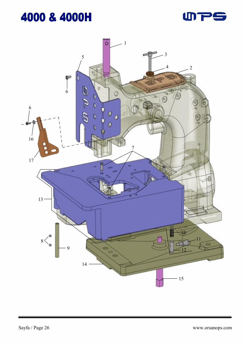
MAKİNE KAPAKLARI CLOTH PLATES AND MISCELLANEOUS COVERS
Sıra No. Seri No. Kul.Ad. Ref No. Part No. Açıklama Description Amt.Req. 1 80673 CB İğne Mili Koruyucu Needle Bar Guard 1 2 40888 Makine Üst Kapağı Arm Cover 1 3 80764 T Cıvata T-Screw 1 4 3573 Somun Nut 1 5 81387 Yan Sac Kapak Face Cover 1 6 22528 Vida Screw 2 7 22574 Vida Screw 3 8 88 Vida Screw 2 9 80437 A Kapak Mili Hinge Pin 1 10 80438 Yay Spring 1 11 80440 Kapak Cıvatası Locking Bolt Knop 1 12 81239 Kapak Pimi Locking Bolt 1 13 81301 D Makine Tablası Cloth Plate Assembly 1 14 4280 A Alt Tabla Base Plate 1 15 33681 Cıvata Screw 1 16 20 Pul Washer 1 17 A 9453 A Parmak Siperi Finger Guard 1

Sayfa / Page 28 www.orsanops.com
1
1
2
2 3
4
3
4
5
5
5
5
6
6
6
6
7
7
7
7 8
9
8
9
10
10
10
10
11
11
11
11
12
12
14 13
14 15
16
17
18
19
20
21 22
23 24
26 27 25
28
29
31
32 33
34 34
35
36
30
37
38
39

Sayfa / Page 29 www.orsanops.com
İP TANSİYON GRUBU VE İP YOLLARI THREAD TENSION AND GUIDE PARTS
Sıra No. Seri No. Kul.Ad. Ref No. Part No. Açıklama Description Amt.Req. 1 HS 106 İp Tertibat Mili Tension Post 2 2 81292 A İp Tertibat Mili Tension Post 2 3 80667 Pim Pin For Tension Discs 2 4 80655 A Pim Pin 2 5 80669 B Pul Bileziği Tension Post Ferrule 4 6 80676 B Tansiyon Pulu Tension Disc 8 7 HA 1349 Yay Burcu Tension Sleeve 4 8 110-2 Tansiyon Yayı Spring For Looper Thread Tension 2 9 HS 110 A Tansiyon Yayı Spring For Needle Thread Tension 2 10 107 Yay Tırtırı Tension Spring Ferrule 4 11 108 Tırtır Somun Tension Nut 4 12 81256 A İp Yolu Thread Sleeve 2 13 AS 3256 İp Yolu Thread Sleeve 2 14 22560 B Vida Screw 4 15 80250 G İp yolu Thread Sleeve 1 16 22894 AD Vida Screw 1 17 95 Vida Screw 1 18 22894 AD Vida Screw 1 19 81254 AG İp Yolu Thread Sleeve 1 20 81254 A İp Yolu Thread Sleeve 1 21 80696 H Yatak Cıvatası Stud 1 22 81350 D İp Yolu Looper Thread Guide 1 23 88 Vida Screw 1 24 80668 A İp Yolu Thread Guide Roller 1 25 81386 A Yay Yatağı Pimi Roller Stud 1 26 12964 C Bilye Tanesi Spring Ball 1 27 HA 1286 B Yay Spring 1 28 G 89 Vida Screw 1 29 81386 Yay Yatağı Pimi (komple) Needle Thread Take-Up Roller 1 30 81365 İp Yolu Yatağı Roller Support 1 31 81365 A İp Yolu Yatağı (komple) Thread Take-Up Roller Guide Assy. 1 32 BP 108 Cıvata Head Cap Screw 1 33 22894 Y Vida Screw 1 34 22894 W Vida Screw 2 35 41559 A Kol Needle Bar Connection 1 36 3254 A İp Yolu Thread Sleeve 2 37 88 Vida Screw 1 38 81267 GA İp yolu Thread Guide 1 39 93 A Vida Screw 1

Sayfa / Page 30 www.orsanops.com
27
2
33
1
3 4
5 6
7
8
9
9
9
10
11
12 13
14
15
16
17 18
19
20
21
22
23
24
25
26
29 28
30
31
32

Sayfa / Page 31 www.orsanops.com
İĞNE HAREKET KOLU BAĞLANTILARI NEEDLE BAR, NEEDLE LEVER
Sıra No. Seri No. Kul.Ad. Ref No. Part No. Açıklama Description Amt.Req. 1 81317 İğne Mili Needle Bar 1 2 77 K Vida Screw 1 3 81356 B İğne Bağı Pulu Needle Stop Plate 1 4 G 89 Vida Screw 1 5 22580 Vida Screw 1 6 96 B Vida Screw 1 7 81356 A İğne Bağı (komple) Needle Holder 1 8 UY 9853 GA 430/172 İğne Needle 2 9 34334 V Boru Burç Link Pin 4 10 HA 54 A Bakla Connecting Link 1 11 33643 Mil Needle Lever Shaft 1 12 22894 J Vida Screw 1 13 22894 H Vida Screw 1 14 98 Vida Screw 2 15 22894 Y Vida Screw 1 16 BP 108 Cıvata Hex. Head Cap Screw 1 17 80715 İğne Kolu Needle Lever 1 18 80774 Blok Guide 1 19 80776 Kol Pimi Stud 1 20 80772 Deri Pul Washer, Leather 1 21 80771 Blok Bağlantı Link 1 22 22894 Y Vida Screw 2 23 80770 Kol Bağlantı Lift Lever 1 24 80769 Bağlantı Blok Sliding Block 1 25 79 Vida Screw 2 26 80768 Bağlantı Parçası Supporting Yoke 1 27 22870 Cıvata Shank Screw 1 28 22894 AD Vida Screw 2 29 92127 Vida Screw 2 30 80732 İğne Mili Bağlantı Kolu Guide Link 1 31 22707 Vida Screw 1 32 907 Somun Nut 1 33 258 Somun Nut 1

Sayfa / Page 32 www.orsanops.com
15
1
3 4 5
2
6
8
7
9
10
11
12
13 14
16 17 18
19
7o
185 mm

Sayfa / Page 33 www.orsanops.com
KRANK BAĞLANTISI VE KASNAK GRUBU CRANK SHAFT AND HANDWHEEL
Sıra No. Seri No. Kul.Ad. Ref No. Part No. Açıklama Description Amt.Req. 1 22587 Vida Screw 2 2 80650 LA Küre Mafsal Yatak Shell 1 3 97 S Vida Screw 1 4 80636 A Çatal Guide Fork 1 5 80656 Saplı Küre Ball Stud 1 6 29066 LA Küre Mafsal Yatak (komple) Needle Lever Ball Link 1 7 80630 C Somun Nut, Left Hand Thread 1 8 80630 Yatak Gerdirici Needle Lever Connecting Rod 1 9 80630 D Somun Nut, Right Hand Thread 1 10 22587 Vida Screw 2 11 80652 Küre Mafsal Yatak Shell 1 12 HA 66 K Kama Woodruff Key 1 13 80885 S Krank Yatağı Kovanı Ball Bearing Assembly For Crank Shaft 1 14 81321 B Kasnak Handwheel 1 15 80621 A Kasnak Göbeği Hub For Handwheel 1 16 80 Vida Screw 3 17 80674 Pul Lock Washer For Hub 1 18 80 Vida Screw 1 19 81322 A Krank Crank Shaft 1

Sayfa / Page 34 www.orsanops.com
57
2
2
3
4
1
5
6 7
8
9
12 11 10
13
14 15 16
18
17
19 20
21
22
23 24
25 26
28
29
27
30
31
32
33
34
35 36
37
38
39
33
41 40
38
35
39
41
42
43
43
42
45
48
49
50
51
54 53
52 55
56
58 59
59 60
60
61
62 63
64
65
66
67
68
69
70
71
47
46
72
73
74
75 76 78
79
80 81
82
83
77
84 85
86
87
44
51 mm

Sayfa / Page 35 www.orsanops.com
LÜPER HAREKET MEKANİZMALARI LOOPER DRIVE MECHANISM
Sıra No. Seri No. Kul.Ad. Ref No. Part No. Açıklama Description Amt.Req. 1 81364 Üst Eksantrik Yatağı Drive Fork For Cross Looper 1 2 94 Vida Screw 4 3 85 Vida Screw 1 4 81364 A Eksantrik Plakası Guide Plate 2 5 9937 Somun Nut 1 6 97 A Vida Screw 2 7 271 E Küre Yatak Shell 1 8 11354 Küre Ball Stud 1 9 81363 A Küre Yatak (komple) Ball Joint Assembly 1 10 18 Somun Nut 1 11 81362 Lüper Gerdirici Connecting Rod 1 12 269 Somun Nut 1 13 97 A Vida Screw 2 14 6040 A Küre Yatak Shell 1 15 11354 Küre Ball Stud 1 16 81363 Küre Yatak (komple) Ball Joint Assembly 1 17 69 H Pul Washer 1 18 9936 Pul Washer 1 19 22824 Vida Screw 2 20 BP 108 Cıvata Hex. Head Cap Screw 1 21 81313 B Çekici Lüper Kolu Cross Looper Lever 1 22 81361 Kanca Hareket Kolu Drive Lever For Cross Looper 1 23 69 H Pul Washer 1 24 9937 Somun Nut 1 25 BP 108 Cıvata Hex. Head Cap Screw 1 26 96 Vida Screw 1 27 81360 Mil Shaft 1 28 95 Vida Screw 2 29 482 Bilezik Collar 1 30 22894 L Vida Screw 1 31 22894 C Vida Screw 1 32 81366 Üçgen Eksantrik Drive Eccentric For Cross Looper 1 33 88 F Vida Screw 8 34 22524 Vida Screw 4 35 81336 A Eksantrik Diski Guide Disc 2 36 98 Vida Screw 2 37 22894 L Vida Screw 2 38 81342 Eksantrik Eccentric 2 39 81349 Küre Ball Stud 2 40 80236 Büyük Küre Yatağı Connection 2 41 G 29442 L Büyük Küre Yatak (komple) Looper Drive Eccentric Assembly 2 42 97 A Vida Screw 4 43 81345 Küre Ball Stud 2 44 G 15442 R Küre Yatak Shell 1 45 G 15442 P Küre Yatak (komple) Ball Joint Assembly 1 46 81348 Tırtırlı Pul Locking Disc 1 47 81345 A Pul Washer 1 48 74 E Vida Screw 1 49 HA 95 Vida Screw 1 50 22580 Vida Screw 2 51 99240 Vida Screw 2 52 81313 Lüper Bağlantı Kolu Lower Looper Lever 1 53 20 Pul Washer 1 54 18 Somun Nut 1 55 90 Vida Screw 1 56 81251 B Tırnak Bağı Mili Shaft For Spreader Lever 1

Sayfa / Page 36 www.orsanops.com
57
2
2
3
4
1
5
6 7
8
9
12 11 10
13
14 15 16
18
17
19 20
21
22
23 24
25 26
28
29
27
30
31
32
33
34
35 36
37
38
39
33
41 40
38
35
39
41
42
43
43
42
45
48
49
50
51
54 53
52 55
56
58 59
59 60
60
61
62 63
64
65
66
67
68
69
70
71
47
46
72
73
74
75 76 78
79
80 81
82
83
77
84 85
86
87
44
95,5 mm

Sayfa / Page 37 www.orsanops.com
LÜPER HAREKET MEKANİZMALARI LOOPER DRIVE MECHANISM
Sıra No. Seri No. Kul.Ad. Ref No. Part No. Açıklama Description Amt.Req. 57 81354 Burç Bushing 2 58 81255 A Mil Yatağı Bearing For Spreader Lever Shaft 1 59 81257 Pul Washer 2 60 74 A Cıvata Screw 2 61 18 Somun Nut 1 62 20 Pul Washer 1 63 96 B Vida Screw 2 64 99240 Vida Screw 2 65 81313 A Lüper Bağlantı Kolu Spreader Lever 1 66 18 Somun Nut 1 67 81337 Lüper Kolu Bağlantısı Rocker Lever 1 68 80691 Konik Somun Nut 2 69 74 A Cıvata Hex. Head Cap Screw 2 70 81338 Küre Bağlantısı Rocker Lever 1 71 81240 Mil Rocker Shaft For Looper Drive 1 72 BP 108 Cıvata Hex. Head Cap Screw 1 73 81339 Lüper Kolu Bağlantısı Drive Lever For Upper Spreader 1 74 18 Somun Nut 1 75 97 A Vida Screw 2 76 81358 A Küre Yatak Shell 1 77 HS 36 K Pul Washer 1 78 81358 B Küre Ball Stud 1 79 81358 Küre Yatak (komple) Ball Joint Assembly 1 80 18 Somun Nut 1 81 35741 A Yatak Gerdirici Connecting Rod 1 82 269 Somun Nut 1 83 97 A Vida Screw 2 84 81357 A Küre Yatak Shell 1 85 81345 Küre Ball Stud 1 86 81357 Küre Yatak (komple) Ball Joint Assembly 1 87 81348 Tırtırlı Pul Locking Disc 1

Sayfa / Page 38 www.orsanops.com
36
1
2 3 4
5 6 6
7 7
8
9 10
11
8
12
13
14
15
15
16
16 17
19
18
20
19
200
21 21
22
23
24
25 26
8
27
28
29
30 31 32
33
34
35
37 38
39
40
41 42
43
44
45
46
47
48 49
52
51
50
46
54 55
56
53
57
130±mm 5 1/8±0.40in.

Sayfa / Page 39 www.orsanops.com
ALT VE ÜST DİŞLİ HAREKET MEKANİZMALARI UPPER AND LOWER FEED DRIVE MECHANISM
Sıra No. Seri No. Kul.Ad. Ref No. Part No. Açıklama Description Amt.Req. 1 80740 Mil Drive Shaft 1 2 BP 108 Cıvata Hex. Head Cap Screw 1 3 80790 Ayar Kolu Rocker Lever 1 4 21711 Somun Nut 1 5 21712 Pul Washer 1 6 98 Vida Screw 2 7 51147 Burç Collar 2 8 18 Somun Nut 3 9 21212 Pul Ring 1 10 81234 A Üst Dişli Kolu Feed Lever 1 11 81235 Kol Pimi Stud 1 12 BP 108 Cıvata Hex. Head Cap Screw 1 13 80791 Üst Transport Hareket Kolu Drive Lever 1 14 HS 36 K Pul Washer 1 15 97 A Vida Screw 4 16 36 E Küre Ball Stud 2 17 80755 Küre Yatak (komple) Connecting Link Assembly 1 18 11 Mil Feed Bar Shaft 1 19 96 B Vida Screw 4 20 482 C Bilezik Collar 2 21 22596 B Vida Screw 2 22 80233 Dişli Kızağı Hareket Kolu Feed Rocker 1 23 8 A Mil Feed Rocker Shaft 1 24 88 A Vida Screw 2 25 81334 Dişli Kızağı (5,35) Feed Bar (5,35) 1 26 20 Pul Washer 1 27 97 X Vida Screw 1 28 93 A Vida Screw 1 29 HA 23 Eksantrik Plakası Guide Plate 1 30 96 Vida Screw 1 31 HA 43 X Eksantrik Feed Lift Eccentric 1 32 HA 10 B Eksantrik Gönye Plakası Guide 1 33 93 A Vida Screw 2 34 HS 70 A Yağ Keçesi Oil Felt 1 35 10 A Yağ Keçesi Oil Felt 1 36 AS 70 A Yağ Keçesi Yatağı Holder For Oil Felt 1 37 HA 18 A Somun (5,35mm) Nut (5,35mm) 1 38 HA 20 A Pul Washer 1 39 80654 Yatak Burcu Bushing 1 40 22587 Vida Screw 2 41 22894 L Vida Screw 1 42 81395 Eksantrik Eccentric 1 43 81351 Eksantrik Yatağı Connecting Link 1 44 G 29099 R Eksantrik Yatağı (komple) Feed Drive Eccentric 1 45 80696 Yatak Burç Cıvatası Stitch Regulating Stud 1 46 22587 Vida Screw 2 47 1230 A Küre Yatak Shell 1 48 21710 Küre Ball Stud 1 49 G 29139 Küre Mafsal Yatak (komple) Ball Link 1 50 80630 C Somun Nut 1 51 80730 Yatak Gerdirici Connecting Rod 1 52 80630 D Somun Nut 1 53 15430 M Küre Mafsal Yatak Shell 1 54 22894 C Vida Screw 1 55 22894 L Vida Screw 1 56 81306 Eksantrik Eccentric 1 57 G 29099 Q Küre Yatak (komple) Drive Eccentric Assembly 1

Sayfa / Page 40 www.orsanops.com
4
1 2
3
5
4 5
6 7
8
9
11
10
12
13
17
16
15
14
Sayfa / Page 41 www.orsanops.com
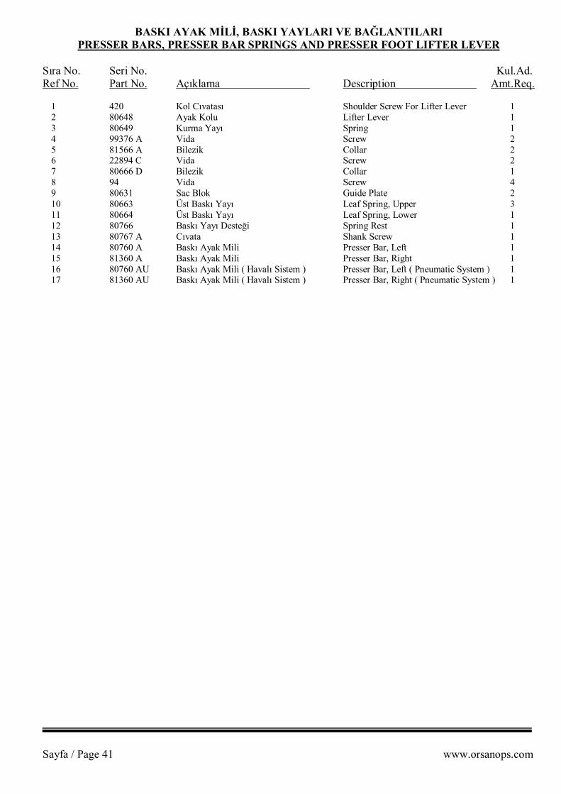
BASKI AYAK MİLİ, BASKI YAYLARI VE BAĞLANTILARI PRESSER BARS, PRESSER BAR SPRINGS AND PRESSER FOOT LIFTER LEVER
Sıra No. Seri No. Kul.Ad. Ref No. Part No. Açıklama Description Amt.Req. 1 420 Kol Cıvatası Shoulder Screw For Lifter Lever 1 2 80648 Ayak Kolu Lifter Lever 1 3 80649 Kurma Yayı Spring 1 4 99376 A Vida Screw 2 5 81566 A Bilezik Collar 2 6 22894 C Vida Screw 2 7 80666 D Bilezik Collar 1 8 94 Vida Screw 4 9 80631 Sac Blok Guide Plate 2 10 80663 Üst Baskı Yayı Leaf Spring, Upper 3 11 80664 Üst Baskı Yayı Leaf Spring, Lower 1 12 80766 Baskı Yayı Desteği Spring Rest 1 13 80767 A Cıvata Shank Screw 1 14 80760 A Baskı Ayak Mili Presser Bar, Left 1 15 81360 A Baskı Ayak Mili Presser Bar, Right 1 16 80760 AU Baskı Ayak Mili ( Havalı Sistem ) Presser Bar, Left ( Pneumatic System ) 1 17 81360 AU Baskı Ayak Mili ( Havalı Sistem ) Presser Bar, Right ( Pneumatic System ) 1
Sayfa / Page 42 www.orsanops.com
2
1
11
9
3 3A 3B
4 4A 4B 5
7 6
8 8A 8B 9
10
12
14 15
16
17
18
19
20 21 22
23 24
25
26
29
28 27
30 31
33
32
34
35
13
1A
10A

Sayfa / Page 43 www.orsanops.com
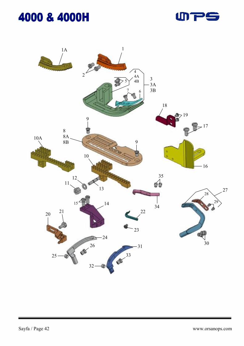
DİKİŞ PARÇALARI SEWING PARTS
Sıra No. Seri No. Kul.Ad. Ref No. Part No. Açıklama Description Amt.Req. 1 41326 Üst Dişli Feed Dog, Upper 1 1A 81326 Üst Dişli Feed Dog, Upper 1 2 136 A Vida Screw 2 3 81320 C Baskı Ayağı (Komple) Presser Foot Assy. 1 3A 81320 CU Baskı Ayağı (Komple-Yuvarlak Fitilli) Presser Foot Assy. For Filler Cord 1 3B 81320 CA Baskı Ayağı (Komple-Yassı Fitilli) Presser Foot Assy. For Flat Tape 1 4 81330 C Baskı Ayağı (Tek) Presser Foot Bottom 1 4A 81330 CU Baskı Ayağı (Tek-Yuvarlak Fitilli) Presser Foot Bottom For Filler Cord 1 4B 81330 CA Baskı Ayağı (Tek-Yassı Fitilli) Presser Foot Bottom For Flat Tape 1 5 22596 B Vida Screw 2 6 81597 A 10 Baskı Ayak Dili Presser Foot Tongue 1 7 22596 B Vida Screw 2 8 81324 A Plaka Throat Plate 1 8A 81324 A-YUV Plaka (Yuvarlak Fitilli) Throat Plate For Filler Cord 1 8B 81324 A-YAS Plaka (Yassı Fitilli) Throat Plate For Flat Tape 1 9 78057 Vida Screw 2 10 41305 A Alt Dişli Feed Dog, Lower 1 10A 81305 A Alt Dişli Feed Dog, Lower 1 11 HA 18 A Somun “5,35” Nut “5,35” 1 12 20 Pul Washer 1 13 99241 Saplama “5,35” Stud Bolt “5,35” 1 14 81585 Plaka Dayaması Throat Plate Support 1 15 22517 Vida Screw 2 16 81303 F Kumaş Dayama Edge Guide 1 17 22514 Vida Screw 2 18 81503 A Kumaş Dayama Dili Stitch Tongue 1 19 HS 24 C Vida Screw 2 20 81325 İğne Siperi Needle Guard 1 21 22567 Vida Screw 1 22 81511 Lüper Tırnağı Thread Retainer For Overedge Stitch 1 23 90 Vida Screw 1 24 81508 Üst Lüper Looper, Lower For Overedge Stitch 1 25 74 E Vida Screw 1 26 99240 Vida Screw 1 27 81507 Alt Lüper Spredaer, Upper For Overedge Stitch 1 28 81310 Lüper Tırnağı Thread Hook 1 29 22 KH Vida Screw 2 30 99240 Vida Screw 2 31 41308 C Kör Lüper Looper For Double Locked Stitch 1 32 HA 95 Vida Screw 1 33 99240 Vida Screw 1 34 81311 B Çekici Lüper Cross Looper For Double Locked Stitch 1 35 22824 Vida Screw 2

Sayfa / Page 44 www.orsanops.com
1
1
2
3
4
5
5
6 7
8
9
10
11
12

Sayfa / Page 45 www.orsanops.com
HAVALI SİSTEM PARÇALARI PNEUMATIC PARTS
Sıra No. Seri No. Kul.Ad. Ref No. Part No. Açıklama Description Amt.Req. 1 03020 Hava Rakoru Coupling 3 2 0302166 Hava Rakoru Coupling 1 3 235050 Piston – Tek Etkili Air Cylinder 1 4 235049 Piston – Çift Etkili Air Cylinder 1 5 98 Vida Screw 2 6 A 34455 B Piston Bağlantı Connection 1 7 A 4455 Piston Bağlantı Sacı Bracket 1 8 74 A Cıvata Screw 3 9 81257 Pul Washer 3 10 450-1950 Somun Nut 2 11 45291 Somun Nut 2 12 A 34455 D Piston Mili Sonlandırıcı Cylinder Rod End 2

Sayfa / Page 46 www.orsanops.com
PARÇA ARAMA LİSTESİ
NUMERICAL INDEX OF PARTS

Sayfa / Page 47 www.orsanops.com
PARÇA NO. SAYFA PARÇA NO. SAYFA PARÇA NO. SAYFA PART NO. PAGE PART NO. PAGE PART NO. PAGE 03020 45 22587 39 41308 C 43 0302166 45 22596 B 43 41326 43 10 A 39 22707 31 41559 A 29 107 29 22824 35 420 41 108 29 22824 43 4280 A 27 11 39 22870 31 450-1950 45 110-2 29 22891 25 45291 45 11354 35 22894 AD 29 482 35 1230 A 39 22894 AD 31 482 C 39 12964 C 29 22894 C 35 51147 39 12987 AG 25 22894 C 39 6040 A 35 12987 AS 25 22894 C 41 666-79 25 136 A 43 22894 H 31 69 H 35 15430 M 39 22894 J 25 74 A 37 15465 F 25 22894 J 31 74 A 37 18 35 22894 K 25 74 A 45 18 37 22894 L 35 74 E 35 18 39 22894 L 39 74 E 43 20 27 22894 W 25 77 K 31 20 35 22894 W 29 78057 43 20 37 22894 Y 29 79 31 20 39 22894 Y 31 8 A 39 20 43 235049 45 80 33 21212 39 235050 45 80233 39 21710 39 258 31 80236 35 21711 39 269 35 80250 G 29 21712 39 269 37 80293 A 25 22 KH 43 271 E 35 80437 A 27 22514 43 29066 LA 33 80438 27 22517 43 29111 C 25 80440 27 22524 35 3254 A 29 80621 A 33 22528 25 33643 31 80630 33 22528 27 33681 27 80630 C 33 22539 25 34334 V 31 80630 C 39 22560 A 25 3573 27 80630 D 33 22560 B 29 35741 A 37 80630 D 39 22560 S 25 36 E 39 80631 41 22567 43 3640 SA 25 80636 A 33 22574 27 40846 25 80644 25 22580 31 40888 27 80648 41 22580 35 41240 DA 25 80649 41 22587 33 41305 A 43 80650 LA 33

Sayfa / Page 48 www.orsanops.com
PARÇA NO. SAYFA PARÇA NO. SAYFA PARÇA NO. SAYFA PART NO. PAGE PART NO. PAGE PART NO. PAGE 80652 33 80885 C 25 81336 A 35 80654 39 80885 S 25 81337 37 80655 A 29 80885 S 33 81338 37 80656 33 81234 A 39 81339 37 80663 41 81235 39 81342 35 80664 41 81239 27 81345 35 80666 D 41 81240 37 81345 37 80667 29 81251 B 35 81345 A 35 80668 A 29 81254 A 29 81348 35 80669 B 29 81254 AG 29 81348 37 80673 CB 27 81255 A 37 81349 35 80674 33 81256 A 29 81350 D 29 80676 B 29 81257 37 81351 39 80691 37 81257 45 81354 25 80692 EA 25 81260 25 81354 37 80694 DA 25 81261 25 81356 A 31 80694 DA 25 81267 GA 29 81356 B 31 80696 39 81292 A 29 81357 37 80696 H 29 81301 D 27 81357 A 37 80715 31 81303 F 43 81358 37 80730 39 81305 A 43 81358 A 37 80732 31 81306 39 81358 B 37 80740 39 81310 43 81360 35 80755 39 81311 B 43 81360 A 41 80760 A 41 81313 35 81360 AU 41 80760 AU 41 81313 A 37 81361 35 80764 27 81313 B 35 81362 35 80766 41 81317 31 81363 35 80767 A 41 81320 C 43 81363 A 35 80768 31 81320 CA 43 81364 35 80769 31 81320 CU 43 81364 A 35 80770 31 81321 B 33 81365 29 80771 31 81322 A 33 81365 A 29 80772 31 81324 A 43 81366 35 80774 31 81324 A-YAS 43 81373 A 25 80776 31 81324 A-YUV 43 81386 29 80790 39 81325 43 81386 A 29 80791 39 81326 43 81387 27 80846 25 81330 C 43 81395 39 80862 25 81330 CA 43 81503 A 43 80885 25 81330 CU 43 81507 43 80885 B 25 81334 39 81508 43
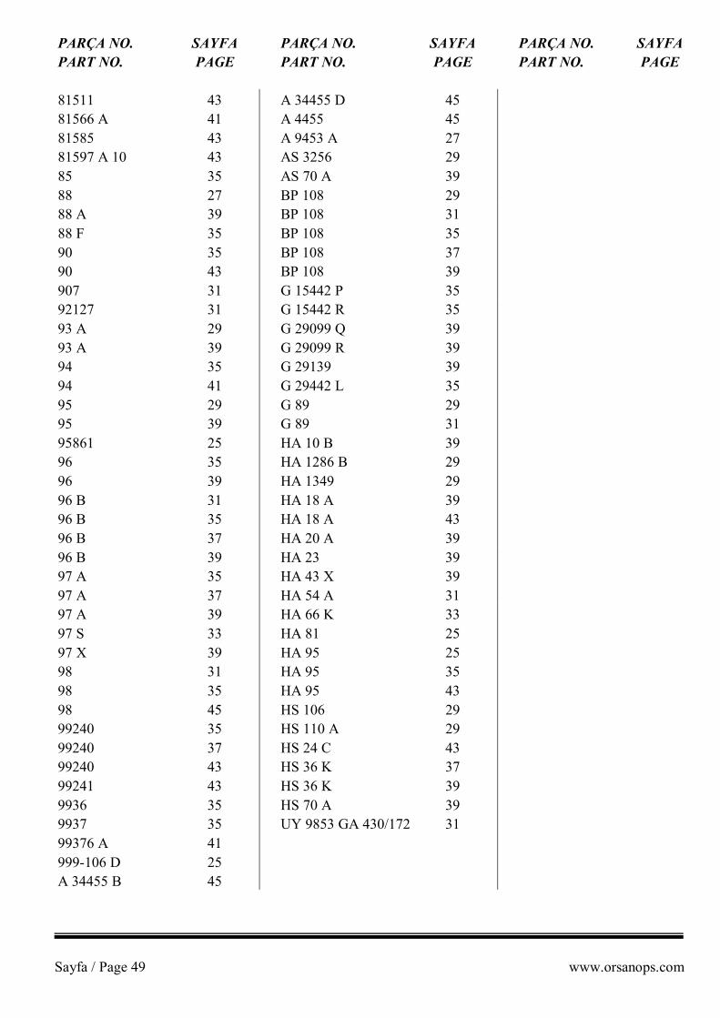
Sayfa / Page 49 www.orsanops.com
PARÇA NO. SAYFA PARÇA NO. SAYFA PARÇA NO. SAYFA PART NO. PAGE PART NO. PAGE PART NO. PAGE 81511 43 A 34455 D 45 81566 A 41 A 4455 45 81585 43 A 9453 A 27 81597 A 10 43 AS 3256 29 85 35 AS 70 A 39 88 27 BP 108 29 88 A 39 BP 108 31 88 F 35 BP 108 35 90 35 BP 108 37 90 43 BP 108 39 907 31 G 15442 P 35 92127 31 G 15442 R 35 93 A 29 G 29099 Q 39 93 A 39 G 29099 R 39 94 35 G 29139 39 94 41 G 29442 L 35 95 29 G 89 29 95 39 G 89 31 95861 25 HA 10 B 39 96 35 HA 1286 B 29 96 39 HA 1349 29 96 B 31 HA 18 A 39 96 B 35 HA 18 A 43 96 B 37 HA 20 A 39 96 B 39 HA 23 39 97 A 35 HA 43 X 39 97 A 37 HA 54 A 31 97 A 39 HA 66 K 33 97 S 33 HA 81 25 97 X 39 HA 95 25 98 31 HA 95 35 98 35 HA 95 43 98 45 HS 106 29 99240 35 HS 110 A 29 99240 37 HS 24 C 43 99240 43 HS 36 K 37 99241 43 HS 36 K 39 9936 35 HS 70 A 39 9937 35 UY 9853 GA 430/172 31 99376 A 41 999-106 D 25 A 34455 B 45

Sayfa / Page 50 www.orsanops.com