Embed Size (px)
Citation preview

SC-4 Routing and Control System
System Setup and Operations Guide

ii SC-4
SC-4 Routing and Control Customizing Guide
• Document Number: 82101-0100
• Document Version: 2.4.1
• Date: December 3, 2015
• Printed in U.S.A.
Copyrights and Trademarks
© 2015 Utah Scientific, Inc., All rights reserved. Any use or reproduction of this guide’s con-tents without the prior written consent of Utah Scientific, Inc. is strictly prohibited.
• SC-4 is a trademark of Utah Scientific, Inc.
• Windows(TM) is a registered trademark of Microsoft Corporation.
• All other product names and any registered or unregistered trademarks mentioned in this guide are used for identification purposes only and remain the exclusive property of their respective owners.
Notice
Information contained in this guide is subject to change without notice or obligation. While every effort has been made to ensure that the information is accurate as of the publication date, Utah Scientific, Inc. assumes no liability for errors or omissions. In addition, Utah Scientific, Inc. assumes no responsibility for damages resulting from the use of this guide.
FCC Compliance (USA) and Digital Equipment Compliance (Canada)
This equipment has been tested and found to comply with the limits for a Class A, digital device, pursuant to Part 15, Subpart B of the FCC Rules and the Canadian EMC Requirement (ICES-003). These limits are designed to provide reasonable protection against harmful interference when the equipment is operated in a commercial environment. This equipment generates, uses, and can radiate radio frequency energy and, if not installed and used in accordance with the instruction manual, may cause harmful interference to radio communications. Operation of this equipment in a residential area is likely to cause harmful interference, in which case, the user will be required to correct the interference at their own expense. Shielded cables must be used to ensure compliance with the FCC Class A limits.

Setup and Operations Guide
Declaration of Conformity
Utah Scientific, Inc.
4750 Wiley Post Way, Suite 150Salt Lake City, Utah 84116-2878 U.S.A.
We declare our sole responsibility that the Utah-400 Digital Routing Switcher is in conformance with the following standards:
Emission
• EN55022:1994+A1&A2
Immunity
• EN55024:1998
• EN61000-3-2
• EN61000-3-3
Safety
• IEC 60950-1:2001 /EN 60950-1:2001
Following the provisions of the Directive(s) of the Council of the European Union:
• EMC Directive 89/336/EED
• Low Voltage Electrical Directive 72/23/EEC
Utah Scientific, Inc. hereby declares that the product specified above conforms to the above Directive(s) and Standard(s).

iv SC-4
Important Safeguards and Notices
This section provides important safety guidelines for the Operator and Service Personnel. Specific warnings and cautions are found throughout the guide where they apply, but may not appear here. Please read and follow the important safety information, specifically those instructions related to risk of fire, electric shock, or injury to persons.
Safety Symbols
•Hazardous Voltage symbol
•Caution symbol. The product is marked with this symbol when it is necessary to refer to the manual to prevent damage to the product.
Warnings
Please observe the following important warnings:
•Any instructions in this guide that require opening the chassis, changing a power supply, or removing a board, should be performed by qualified personnel only. To reduce the risk of electric shock, do not perform any service unless you are qualified to do so.
•Heed all warnings on the unit and in the operating instructions.
•Do not use this product in or near water. Disconnect AC power before installing any options or servicing the unit unless instructed to do so by this manual.
•This product is grounded through the power cord ground conductor. To avoid electric shock, plug the power cord into a properly wired receptacle before con-necting the product inputs or outputs.
•Route power cords and other cables so they won’t be damaged.
•The AC receptacle (socket) should be located near the equipment and be easily accessible.
•Disconnect power before cleaning. Do not use any liquid or aerosol cleaner - use only a damp cloth.

Setup and Operations Guide v
•Dangerous voltages exist at several points in this product. To avoid personal injury, do not touch exposed conductors and components while power is on. Do not insert anything into either of the systems two-power supply cavities with power connected.
•Do not wear hand jewelry or watches when troubleshooting high current cir-cuits, such as power supplies. During installation, do not use the door handles or front panels to lift the equipment as they may open abruptly and injure you.
•To avoid fire hazard when replacing fuses, use only the specified correct type, voltage and current rating as referenced in the appropriate parts list for this product. Always refer fuse replacement to qualified service personnel.
•Have qualified personnel perform safety checks after any service.
Cautions
Please observe the following important cautions:
•When installing this equipment do not install power cords to building surfaces. To prevent damage when replacing fuses, locate and correct the problem that caused the fuse to blow, before reconnecting power.
•Use only specified replacement parts
Notices
Please observe the following important notes:
• When the adjacent symbol is indicated on the chassis, please refer to the man-ual for additional information.
• For the HD-2020 Chassis and Master Control Panel, refer to “Connecting and Disconnecting Power” - Chapter 2 (Hardware Installation).

vi SC-4
Company Information
Utah Scientific, Incorporated
4750 Wiley Post Way, Suite 150Salt Lake City, Utah 84116-2878 U.S.A.
• Telephone: +1 (801) 575-8801
• FAX: +1 (801) 537-3098
• Technical Services (voice): +1 (800) 447-7204
• Technical Services (FAX): +1 (801) 537-3069
• E-Mail -General Information: [email protected]
• E-Mail -Technical Services: [email protected]
• World Wide Web: http://www.utahscientific.com
• After Hours Emergency: +1 (800) 447-7204. Follow the menu instructions for Emergency Service.

Setup and Operations Guide
Warranty Policies
Hardware Warranty
Utah Scientific, Inc. warrants to the original purchaser that the Utah Scientific hardware is free from defects in materials and workmanship and will perform substantially in accordance with the accompanying written materials under normal use and service for a period of ten (10) years from the date of shipment. Any implied warranties on hardware are limited to ten (10) years. Some states/jurisdictions do not allow limitations on duration of an implied warranty, so the above limitation may not apply to certain specific purchasers.
Software Warranty
Utah Scientific warrants that the software will perform substantially in accordance with the accompanying written materials for a period of one (1) year from the date of shipment.
Customer Remedies
For the first one (1) year after purchase of the software and the first ten (10) years after the date of purchase of the hardware, Utah Scientific’s and its suppliers’ entire liability and purchaser’s exclusive remedy shall be, at Utah Scientific’s option, either:
• Return of the price paid, or
• Repair or replacement of the software or hardware that does not meet the above warranties and is returned to Utah Scientific under the returned materials authorization (RMA) process with freight and forwarding charges paid.
After the initial warranty periods, purchaser’s exclusive remedy is the repair or replacement of the hardware upon payment of a fixed fee to cover handling and service costs based on Utah Scientific’s then-current price schedule. The above warranties are void if failure of the software or hardware has resulted from an accident, abuse, or misapplication. Any replacement software or hardware will be warranted for the remainder of the original warranty period or thirty (30) days, whichever is longer.

viii SC-4
No other warranties. To the maximum extent permitted by applicable law, Utah Scientific and its suppliers disclaim all other warranties, either express or implied, including, but not limited to implied warranties of merchantability and fitness for a particular purpose, with regard to the software, the accompanying written materials, and any accompanying hardware. This limited warranty gives the purchaser specific legal rights. These rights may vary in certain states/jurisdictions.
No liability for consequential damages. To the maximum extent permitted by applicable law, in no event shall Utah Scientific or its suppliers be liable for any damages whatsoever (including without limitation, damages for loss of business profits, business interruption, loss of business information, or any other pecuniary loss) arising out of the use of or inability to use Utah Scientific products, even if Utah Scientific has been advised of the possibility of such damages. Because some states/jurisdictions do not allow the exclusion or limitation of liability for consequential or incidental damages, the above limitation may not apply in those circumstances.
SC-4 Setup and Operations Guide i
SC-4 Routing and Control Customizing Guide
Table of Contents
SC-4 Routing and Control Customizing Guide
Copyrights and Trademarks ....................................... ii
Notice ......................................................................... ii
FCC Compliance ........................................................... ii
Declaration of Conformity .......................................... iii
Important Safeguards and Notices ............................ iv
Company Information ................................................. vi
Warranty Policies ....................................................... vii
CHAPTER 1 Introduction
In this Guide ............................................................... 1-1
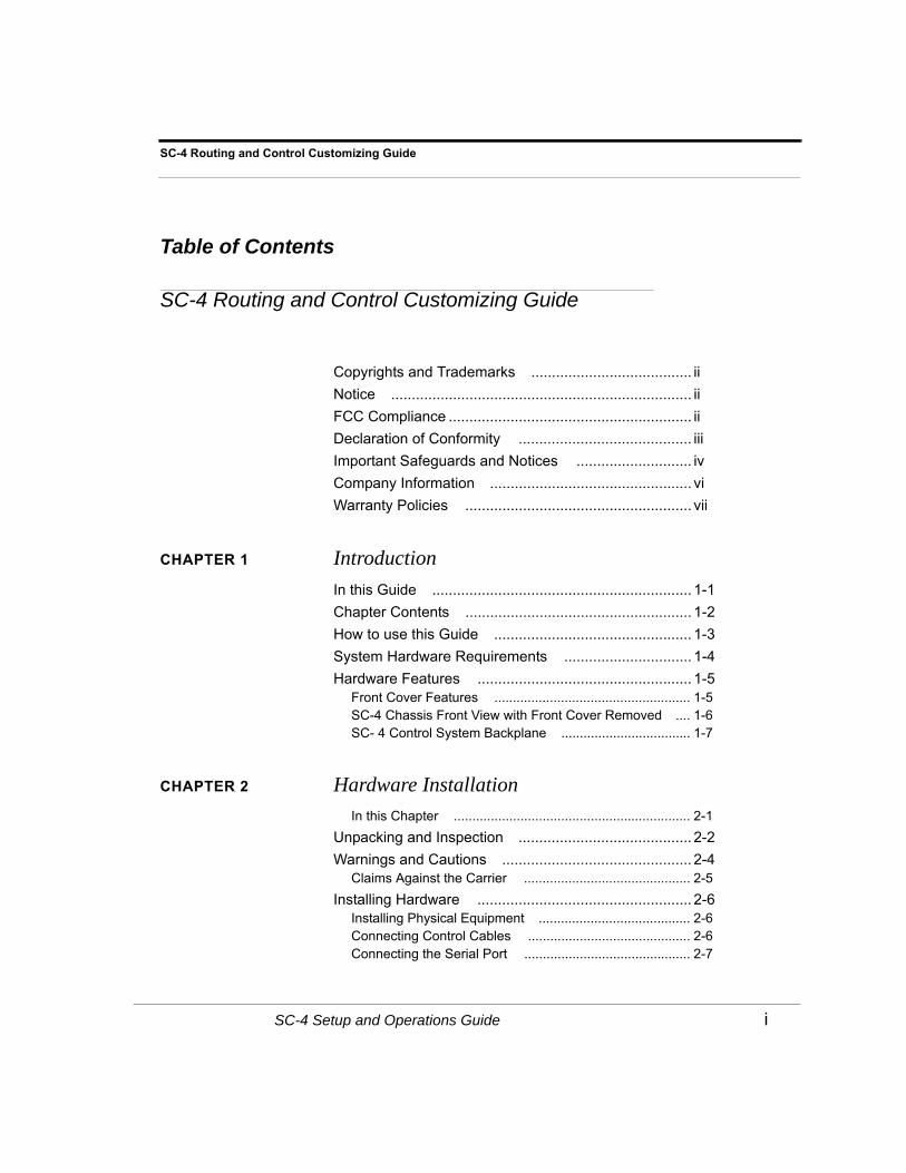
Chapter Contents ....................................................... 1-2
How to use this Guide ................................................ 1-3
System Hardware Requirements ............................... 1-4
Hardware Features .................................................... 1-5Front Cover Features ..................................................... 1-5SC-4 Chassis Front View with Front Cover Removed .... 1-6SC- 4 Control System Backplane ................................... 1-7
CHAPTER 2 Hardware Installation
In this Chapter ................................................................ 2-1
Unpacking and Inspection .......................................... 2-2
Warnings and Cautions .............................................. 2-4Claims Against the Carrier ............................................. 2-5
Installing Hardware .................................................... 2-6Installing Physical Equipment ......................................... 2-6Connecting Control Cables ............................................ 2-6Connecting the Serial Port ............................................. 2-7

ii Table of Contents
Connecting the Sync Ports ..............................................2-7Connecting Power - AC Systems ....................................2-8DC Power Connectivity ...................................................2-10Cable Considerations ......................................................2-11
SC-4 Setup and Operations ....................................... 2-12Overview .........................................................................2-12Unpacking and Installation Instructions ...........................2-12Connecting All Pieces to SC4 Chassis ...........................2-13Applying Power to SC4 Chassis .....................................2-18Changing IP address for SC4 chassis ............................2-18Changing the Chassis ID ................................................2-19Setting the Correct Time and Date ..................................2-20Proper Hot Swappable Removal of SC4 Cards ..............2-21Changing Serial Port Settings .........................................2-22Ethernet LEDs .................................................................2-25System LEDs ..................................................................2-25Sync LEDs ......................................................................2-25Power Supply LEDs ........................................................2-25
CHAPTER 3 System Configuration
In this Chapter .................................................................3-1
SC-4 Control Board System Operation ...................... 3-2Redundant Operation ......................................................3-2The Debug Port ...............................................................3-2
The SC-4 Control Board ............................................ 3-3SC-4 Front View Components and Functions .................3-3The SC-4 Control Board Hardware Settings ...................3-4Hardware Changes on the SC-4 Control Board ..............3-5
SC-4 Control Board Error and Status LED’s .............. 3-7Power Supply LED’s .......................................................3-7
System LED’s ............................................................ 3-9
The SC-4 Monitor Display Operation ......................... 3-11Features and Functions of the SC-4 Monitor Display .....3-11Monitor Display Formats .................................................3-12
The SC-4 Power - Supply and Connections .............. 3-18Voltage Alarms ................................................................3-19SC – 4 Power Supply – Top View ...................................3-20

SC-4 Setup and Operations Guide iii
SC-4 Routing and Control Customizing Guide
The SMPTE and Remote Alarms ............................... 3-21Alarm Port Pin-Outs ........................................................ 3-22Serial Port Pinouts .......................................................... 3-22
CHAPTER 4 Operations
In this Chapter ................................................................ 4-1
SC4 Operations ......................................................... 4-2The Debug Port .............................................................. 4-2Physical Connection ....................................................... 4-2Terminal Emulation software setup ................................. 4-2General Status ................................................................ 4-2Specific Operations ........................................................ 4-3Shutting down the SC4 application ................................ 4-4Resetting the SC4 .......................................................... 4-4Gathering data from the onboard log .............................. 4-5
APPENDIX A Audio Attributes Notice
Important Note ................................................................ A-1
APPENDIX B System Timing Consideration
Overview ....................................................................B-1Switching Example ......................................................... B-2The Critical Issue ............................................................ B-3Potential Alternatives ...................................................... B-3

iv Table of Contents

List of Figures i
List of Figures
List of Figures
Chapter 1
SC-4 Front Panel Components ...................................................................... 1-5Chassis Front with Cover Removed ............................................................... 1-6SC-4 Backplane with Callouts ........................................................................ 1-7
Chapter 2
SC-4 Basic Packaging and Contents ............................................................. 2-3SC-4 Expanded Packaging and Contents ...................................................... 2-3SC-4 Control System AC Power Connections ................................................ 2-9Burn Encode - screen 1 .................................................................................. 2-22Burn Encode - screen 2 .................................................................................. 2-23Burn Encode - screen 3 .................................................................................. 2-23Burn Encode - screen 4 .................................................................................. 2-24Burn Encode - screen 5 .................................................................................. 2-24
Chapter 3
SC-4 Control Board Components – Front View .............................................. 3-3SC-4 Control Board – Top View ..................................................................... 3-6SW3 Identification – Viewed from the Top Rear of the SC-4 ......................... 3-10Monitor Display Features ................................................................................ 3-11Time Display Edit Parameters ........................................................................ 3-14Date Display Edit Parameters ........................................................................ 3-14Name Display Edit Parameters ...................................................................... 3-14Network Setup Menu Display ......................................................................... 3-15Submenu-1; IP Address 1 .............................................................................. 3-15Submenu-2; IP Mask 1 ................................................................................... 3-15Submenu-3; Broadcast 1 Address .................................................................. 3-16Submenu-4: Route IP Address 1 Address ...................................................... 3-16Submenu-5; Route Mask 1 Address ............................................................... 3-16Submenu 6; Gateway 1 Address .................................................................... 3-16End Display of Network Setup Menu. ............................................................. 3-17Left and Right Power Supplies ....................................................................... 3-18Front View of the SC-4 Power Supply Features ............................................. 3-18SC-4 Power Supply – Top View ..................................................................... 3-20DB-9 Alarm Port Connectors .......................................................................... 3-21

ii SC-4 Routing and Control System
Chapter 4
Chassis terminal display ................................................................................. 4-7
Appendix B
PAL Sync ........................................................................................................ B-2Line Switching ................................................................................................ B-4

Introduction 1-1
CHAPTER 1 Introduction
In this Guide
This guide provides information on installing, configuring, and operating the SC-4 Control System. The following chapters and appendices are included.
• Chapter 1: “Introduction” summarizes the guide and introduces the SC-4 Control System.
• Chapter 2: “Hardware Installation” provides installation instructions for the user. Includes some “do’s” and “don’ts” regarding the installation.
• Chapter 3 “System Configuration” provides information the user needs to know when setting up or changing the SC-4 Control Boards.
• Chapter 4 “Operations” offers a detailed description of connections, software setup, and SC-4 system operations.
Introduction
1-2 Introduction
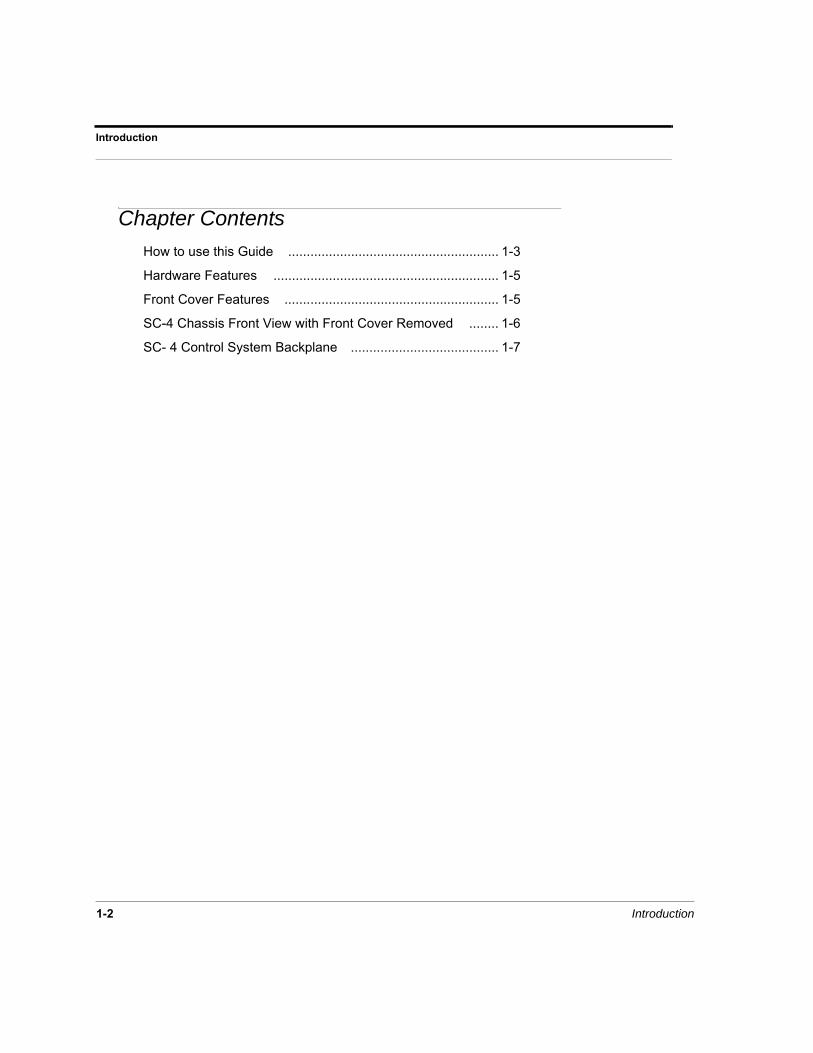
Chapter Contents
How to use this Guide ......................................................... 1-3
Hardware Features ............................................................. 1-5
Front Cover Features .......................................................... 1-5
SC-4 Chassis Front View with Front Cover Removed ........ 1-6
SC- 4 Control System Backplane ........................................ 1-7

SC-4 Control System 1-3
How to use this Guide
How to use this Guide
The chapters in this guide follow a logical sequence from the introduction through specifica-tions.
• Read this chapter “Introduction” to familiarize yourself with the product and its compo-nents.
• Follow the instructions in “Hardware Installation” to install the SC-4 Control System and related components including control panels signal levels and inter-system communica-tions.
• The chapter on “System Configuration” relates directly to the SC-4 Control Card(s) and what can be configured on them.
• “Operations” describes operational commands that can be sent to the SC-4 via Telnet or the system debug port. This section also describes various status messages available at the debug port.

Introduction
1-4 Introduction
System Hardware Requirements
Item Minimum Recommended
Processor Intel Pentium II Intel Pentium IV
Operating System Windows 2000 Windoes XP
Memory 128 MB Ram 512 MB Ram
Hard Disk 384 MB Free Space Including Swap File
--
Monitor 17” 1024x768 Color Monitor
--
Video Card 1024x768 capable, 8 MB of RAM
==
CD-ROM Any Any
Ethernet Adapter 10 Base T --
Serial Port Any Any

SC-4 Control System 1-5
Hardware Features
Hardware Features
The SC-4 Control System is normally shipped with the following components:
• One Front Cover
• One SC-4 Chassis
• Two Power supplies (Redundancy is supplied as standard)
• Two SC-4 Control Cards (Redundancy is supplied as standard)
• Two Power Cords
• Two (2) MX-Bus Terminator
• 8 UNET Terminators
• One PC to RJ-45 Adapter Plug (USI Part Number: 140100-2).
• One SC-4 Control System Users’ Guide (USI PN 82101-0100).
Front Cover Features
FIGURE 1-1. SC-4 Front Panel Components
Figure 1-1 shows the components of the SC-4 Front Panel. The function of each component is explained in the Table below.
SC-4POWER
POWER
Air Vents
Clear Display LensPower Supply Light Pipe
Release LatchRelease Latch
Power Supply Light Pipe

Introduction
1-6 Introduction
SC-4 Chassis Front View with Front Cover Removed
With the front cover removed the following components are visible from the front:
• The SC-4 Control Boards (Normally shipped with two control boards).
• Two Power Supplies.
• One Chassis Monitoring (Display) Module.
Figure 2 shows the location of each of the components.
FIGURE 1-2. Chassis Front with Cover Removed
TABLE 1-1. SC-4 Front Panel Functions
Component Function
Air Vents Allows airflow across the power supplies and control boards with the front cover installed
Release Latch(s) Releases the front cover when each latch is moved toward the center of the chassis.
Power Supply Light Pipes
Will show “Green” when both supplies are operating properly, “Red” indicates a fault
Clear Display Lens Allows the user to view the current display mode without removing the front cover.
PS Alarm
+5
+3.3
+12
-12
TMP
FAN
PS Alarm
+5
+3.3
+12
-12
TMP
FAN
Power Supply Chassis Monitor / Display Board Power Supply
SC-4 Control Board #1 SC-4 Control Board #2

SC-4 Control System 1-7
Hardware Features
SC- 4 Control System Backplane
The SC-4 Backplane provides all of the connections necessary to control Utah Scientific equipment.
• The SC-4 backplane is arranged into the following groups of connectors:
• Eight RJ-45 UNET Connectors
• Four BNC Party Line Connectors
• Three looping sync inputs
• Two RJ-45 Ethernet Connectors
• Two MX-Bus Connectors (25 pin D Connector – Female)
• Six Control Connectors (9 pin D Connector – Female)
Figure 1-3 shows the complete backplane identifying all of the groups above.
FIGURE 1-3. SC-4 Backplane with Callouts
TABLE 1-2. SC-4 Chassis Internal Component Functions
Component Function
Power Supplies 115 VAC – 230 VAC, auto sensing
Monitor / Display Board Selects and displays SC-4 system parameters
Control Boards Provides Control and Configuration
UNET ETHERNET
PARTYLINE1 2 3 4
SYNC 2 SYNC 3
DB-9S(FEMALE)
ALARM
DB-9S(FEMALE)
DB-9S(FEMALE)
SC
DB-9S(FEMALE)
DB-9S(FEMALE)
DB-9S(FEMALE)
DB-9S(FEMALE)
DB-9S(FEMALE)
DB-9S(FEMALE)
CONTROL1 2
4
6
3
5
DB-15P(MALE)
DB-15P(MALE)
DATA BUS
DB-25S (FEMALE)
DB-25S (FEMALE)
MX
SYNC 1
1 2 3 4GPIO
(4) Party Line Ports
(3) Looped-through Sync Ports
(4) GPIO Ports
(1) Alarm Port
(6) Serial Ports
(2) Ethernet Ports(8) UNET Ports
(2) Data Bus Ports(2) MX Bus Ports
AC Plug
AC Plug
(2) SC - Bus Ports
(2) SC - Bus Ports
NOT USED
(2) Data Bus Ports
NOT USED

Introduction
1-8 Introduction
TABLE 1-3. Backplane Connections and Functions
Port Function
AC Plug Connection for the AC Line Power Cord(s).
Party Line Use with CSP Panels or Party Line controlled devices.
UNET For use with UNET based control panels.
Ethernet Standard Ethernet Ports.
GPIO General Purpose Relay / Optos.
Alarm SMPTE and Remote Alarm 0 – 3.
Serial Hardware selectable as RS-232 / RS – 422.
Sync 1 - 3 NTSC Black Burst, PAL Black Burst, or TRI-Level Black Burst

SC-4 - Installation and Operations 2-1
CHAPTER 2 Hardware Installation
In this ChapterUnpacking and Inspection ...............................................2-2
Warnings and Cautions ...................................................2-4Claims Against the Carrier ......................................................... 2-5
Installing Hardware ..........................................................2-6Installing Physical Equipment .................................................... 2-6Connecting Control Cables ........................................................ 2-6Connecting the Serial Port ......................................................... 2-7Connecting the Sync Ports ........................................................ 2-7Connecting Power - AC Systems .............................................. 2-8DC Power Connectivity ..............................................................2-10Cable Considerations ................................................................ 2-11
SC-4 Setup and Operations ............................................2-12Overview .................................................................................... 2-12Unpacking and Installation Instructions ..................................... 2-12Connecting All Pieces to SC4 Chassis ...................................... 2-13Applying Power to SC4 Chassis ................................................2-18Changing IP address for SC4 chassis ....................................... 2-18Changing the Chassis ID ........................................................... 2-19Setting the Correct Time and Date ............................................ 2-20Proper Hot Swappable Removal of SC4 Cards ......................... 2-21Changing Serial Port Settings .................................................... 2-22Ethernet LEDs ........................................................................... 2-22System LEDs ............................................................................. 2-23Sync LEDs ................................................................................. 2-23Power Supply LEDs ................................................................... 2-23

Hardware Installation
2-2 Hardware Installation
Unpacking and Inspection
The SC-4 Control System, when shipped by itself, is packaged in a 25” x 25” x 13” car-ton and encased in Styrofoam. The SC-4 Chassis is in the bottom of the carton and all accessories are packed on top, packaged and wrapped in bubble wrap. See Figure 1-1: SC-4 Basic Packaging and Contents.
When the SC-4 Control System is shipped with control panels or other systems in the same carton it will be in a 25” x 25” x 29” carton and layered with the SC-4 on the bot-tom, other systems or control panels in the second layer and accessories on top. See Figure 1-2: SC-4 Expanded Packaging and Contents.
In either case, the SC-4 is wrapped in anti-static wrap and encased in Styrofoam.
The easiest method of removing the SC-4 Chassis from the package is to:
1. Open the top of the box and remove all the accessories.
2. Cut the sides of the box and break the Styrofoam away from the back of the SC-4 Chassis.
3. Gently pull the SC-4 from the Styrofoam packing.
Inspect the accessories package and inventory it for the following items:
1. Two (2) AC Power Cords.
2. Two (2) MX-Bus Terminators.
3. Two (2) SC-Bus Terminators. (USI Part # 70797-1)
4. Eight (8) UNET Terminators. (USI Part # 65324-04)
5. One (1) PC to RJ-45 adapter Plug; DB-9S to RJ-45 USI PN 140100-2.
6. One (1) SC-4 Control System Users’ Guide; USI PN 82101-0100.
If anything is missing from the above list, contact: Utah Scientific Technical Services at 1.800.447.7204 or your Utah Scientific Sales Representative.

SC-4 Guide 2-3
Unpacking and Inspection
FIGURE 2-1. SC-4 Basic Packaging and Contents
FIGURE 2-2. SC-4 Expanded Packaging and Contents
Styrofoam Lid
Inner Styrofoam Packing
25" x 25" x 13"Cardboard Box
Accessories
SC-4 Control System Chassis
Accessories
Styrofoam Lid
Inner Styrofoam Packing
25" x 25" x 29"Cardboard Box
SC-4 Control System Chassis
Other System Chassis, Control Panels; Etc.

Hardware Installation
2-4 Hardware Installation
Warnings and Cautions
Warning
The SC-4 Control System is designed to be continuously powered up. The power socket should be located near the equipment and easily accessible in case of an emergency.
Potentially lethal AC voltages are present when the SC-4 AC System is powered up. This equipment should be operated and maintained by technically qualified personnel.
Caution
Your warranty does not cover damage resulting from improper handling of, repairs to or unauthorized modifications of your equipment. Refer to the warranty page for further information.
This equipment contains components that are susceptible to damage from electro-static discharges. A static safe environment, including work-stations, tools and containers, is recommended when handling or ship-ping circuit cards or equipment.

SC-4 Guide 2-5
Warnings and Cautions
Claims Against the Carrier
Visually inspect the container your equipment was shipped in. You should receive car-tons in good condition with no visible physical damage such as tearing, crushing punc-ture or water damage.
Make a note of any physical damage to the shipping containers before unpacking them. If possible, note any damage on the shipping invoice from the carrier before you sign for it. In some cases it may be useful to take pictures of the damage to present to the carrier if a claim must be made.
As the SC-4 is unpacked for installation, carefully check for any internal damage. Exam-ine the frame and contents carefully as rough handling may dislodge cards and/or power supplies and cause internal damages not readily noticeable until the equipment is pow-ered up.
File all damage claims with the carrier and contact Utah Scientific for further instructions.
Note: Utah Scientific assumes no responsibility for loss or damage to equip-ment in shipment. You must direct all claims related to such damage to the insurer and / or carrier. Do not return damaged items to Utah Scientific until your claim is authorized and Utah Scientific provides you with a Returned Mate-rials Authorization (RMA).

Hardware Installation
2-6 Hardware Installation
Installing Hardware
The SC-4 Control System installation requires the following steps:
1. Installing the Physical Equipment.
2. Connecting Control Cables.
3. Connecting the Serial Ports.
4. Connecting the Sync Ports.
5. Connecting Power
Installing Physical Equipment
Install the SC-4 Control System in a standard 19 inch rack mount frame.
• The SC-4 Chassis is 3-1/2” high and occupies 2 rack units.
Locate the chassis where it is convenient and accessible with room for cabling and eas-ily accessible.
Connecting Control Cables
Since each site varies considerably, some general rule of thumb should be adhered to when connecting control cables.
• When connecting the MX-Bus Cables they must be terminated at each end of the daisy chain.
• The MX-Bus is a router control bus driven by the SC-4. All equipment with MX-Bus connections contain two female 25-pin ports. The MX bus daisy chains from one piece of equipment to the next, with the unused connector on each end of the MX-Bus receiving a terminator. The cable type used to interconnect multiple chassis is USI part number 80229-XX, where ‘XX’ details the length of the cable. The termina-tor used at each end of the bus is USI part number 70797-1.
• The U-NET is a panel control bus that interfaces UCP or SCP series control panels to the SC-4. Each U-NET port can support up to 32 panels at 1000 feet of cable. Panels can be placed on any one of the U-NET ports without regard to station number, although every panel must have a unique station number. The U-NET daisy chains through the panels (and every unused port). Termination must take place, whether at the back of the SC-4 or at the end of a panel chain, with the USI terminator. part number 65324-04.

SC-4 Guide 2-7
Installing Hardware
• Party Line coax cables do not need termination. If any party line connection does have ter-mination it will cause erratic responses to control signals.
• Unused UNET Ports on the back of the SC-4 must be terminated. Those ports, which are daisy chained to SCP or UCP panels, must be terminated at the end of the daisy chain.
• Ethernet Ports require no termination.
• The Serial Ports do not require termination.
Connecting the Serial PortNote: For additional serial port information, See “Serial Port Pinouts” on page 3-22.
(Default Serial Port Setup)
The Serial Ports are configured as:
• Serial Ports 1, 3 and 5 – 38400 Baud, 8 Data Bits, 1 Stop Bit and No Parity, Indexed.
• Serial Ports 2, 4 and 6 – 19200 Baud, 7 Data Bits, 2 Stop Bits and Even Parity, Numeric.
To select between RS-232 and RS-422:
• Extract the SC-4 Control Board from the chassis.
• The hardware selectable gang-jumpers are located on the Left Edge of the SC-4 Control Board.
• To select RS-232 (default position) – viewed from the front, the gang-jumper should be moved to the Right for the desired port.
• To select RS-422 - viewed from the front, move the gang-jumper to the Left for the desired port.
For more specific information, refer to the Hardware Specifics section of this manual, which also shows the serial port pin-outs.
Connecting the Sync Ports
As a default, the SC-4 uses sync 1 for vertical interval switching.
The sync ports should be fed with analog black burst signals, either NTSC, PAL, or Tri-Level. Do not connect composite sync or digital SDI or HD-SDI signals to these ports.

Hardware Installation
2-8 Hardware Installation
Each Sync must be terminated in the daisy chain with a BNC 75Ohm / 1% terminator (Furnished by Utah Scientific).
Connecting Power - AC Systems
There are two six foot IEC / 18 Gauge power cords furnished with the SC-4 Control System. The power cords connect into the two IEC plugs located on each side of the chassis’ backplane (Refer to Figure 2-3). The SC-4 is capable of full operation with only one power supply operating.
Important: The AC Power Cord is the only method to connect and disconnect power from the SC-4 Control System. The chassis does not have a power switch and is intended to be left ON indefinitely. In case of emergency, the AC power cord should be readily accessible for a quick disconnect.
To connect to system power:
1. On the SC-4 Backplane locate the Left and Right power connector.
2. Using the AC Power Cord, connect each power cord to a stable AC Power Source.

SC-4 Guide 2-9
Installing Hardware
3. Repeat steps 1 and 2 for any additional control systems.
FIGURE 2-3. SC-4 Control System AC Power Connections
DB-9S
(FEMALE)
SC
DB-9S(FEMALE)
DB-9S(FEMALE)
DB-9S(FEMALE)
CONTROL2
4
6
PARTYLINE1 2 3 4
SYNC 1
ACSource
ACSource

Hardware Installation
2-10 Hardware Installation
DC Power ConnectivityThe DC input at the rear of the chassis is noticeably different than its AC counterpart. The connection consists of three separate terminals:
• Ground - Frame or chassis grounding point
• 0V - Most positive leg of -48V DC connection.
• -48V - Most negative leg of -48V DC connection.
Note that this configuration is a DC-I or DC isolated connection.
The terminal strip is a small bracket containing three screws (see 1). Loosen the screws to remove the terminal from the back. This will expose the strip of wire (aprox. 1/4 of an inch).
Proper wire insertion into the removable terminal block
• Turn the screws counter clockwise to allow wire insertion (3 screws on block top).
• Strip 1/4” of the insulation from the new wires.
• Insert wire, then turn screw clockwise to tighten
Use 12 AWG wire (maximum)
The maximum branch circuit protection rating for the circuit feeding the SC-4 is 2 Amps
1

SC-4 Guide 2-11
Installing Hardware
Cable Considerations
Utah Scientific provides some pre-assembled cables for some of the SC-4 connections. You must assemble cables associated with the Serial Ports, GPIO Ports, Alarm Ports and coaxial cables. This section provides some guidelines regarding those cables.
Cables that may be ordered from Utah Scientific
The SC-4 Control System is not normally shipped with any control cables; these are usually shipped with the Utah Scientific routing systems.
The cables provided by Utah Scientific include:
• The MX-Bus Cable - Part Number 80229-10; this cable may be special ordered in lengths up to 50 foot.
Cables that need to be fabricated
• Sync1 and Sync 3 Ports – use any good grade of 75-Ohm coaxial cable.
• Party Line Ports – Utah Scientific recommends using Belden 8281: RG-59, 75-Ohm for lengths greater than 300 Meters (1000’).
• UNET and Ethernet Ports – use Ethernet Category 5, UTP with RJ-45 Connectors. Grounded and shielded cables are recommended.
• Serial Ports – use any 22 Gauge to 24 Gauge twisted pair with DB-9P (male) con-nectors for the SC-4 backplane.
• Alarms Port – use any 22 or 24 Gauge twisted pair with DB-9P (male) connector.
• GPIO Ports – use any 22 or 24 Gauge twisted pair to connect to the TB-1 male Phoenix Connector (furnished with the SC-4 System).

Hardware Installation
2-12 Hardware Installation
SC-4 Setup and Operations
Overview
This section will assist you with configuration and setup for any SC-4 within your facility. Inventory instructions and visual sequences are provided throughout the following steps where necessary.
Please contact Utah Scientific Customer Service if you have additional questions.
Unpacking and Installation Instructions
1. Inspect the SC4 equipment making sure that the SC4 cards and power supplies are still inserted firmly in their proper slots. A fully populated (redundant) chassis will have two cards installed horizontally in the upper two slots with one power supply on each side. A non-redun-dant system will have one SC4 only installed in the upper slot but still requires the use of two power supplies. There should also be a time display module on the lower portion of the chas-sis.
(REDUNDANT AND NON-REDUNDANT SYSTEMS
Redundant
Non-Redundant

SC-4 Guide 2-13
SC-4 Setup and Operations
2. List of materials includes:
a. (1) SC4 2 RU chassis
b. (2) SC4 control cards (redundant system) and 1 SC4 card (non-redundant)
c. (2) power supplies
d. (2) AC power cords
e. (8) UNET terminators (RJ45)
f. (2) MX-Bus Terminators
g. (1) System CD (containing SC-4 manual and rMan software)
h. (1) RJ45 to 9 pin adapter labeled SC4/2020
3. Find the best location to install the chassis that will accommodate the various connections which include – MX-Bus to router chassis, UNET to UNET type control panels, Ethernet to PC and Ethernet type control panels, SYNC to analog house black source, Party Line ports to Party Line type control panels and serial ports to automation type equipment.
Description of SC4 Chassis, Cards and Power Supplies
1. MX-Bus ports – 2 total – located in lower right section on rear of chassis.
2. UNET ports – 8 total – located center top on rear of chassis.
3. Ethernet ports – 2 total – located just right of the UNET ports on rear of chassis.
4. SYNC ports – 3 total – located upper left on rear of chassis.
5. Party Line ports – 4 total – located upper left on rear of chassis.
Connecting All Pieces to SC4 Chassis
Note: Make all connections to rear of SC4 before applying power
1. MX-Bus cable connections
a. UTSCI provides one 10’ MX-Bus cable for each chassis that uses the MX data bus. These include UT400, UT300, UT200, MXLator and MX-Hub equipment.
b. There are two possible options for connecting the various MX-Bus equipment. Option 1 is to connect one end of a cable to a single port on the SC4 chassis and the other end to either of

Hardware Installation
2-14 Hardware Installation
the dual ports on the MX-bus equipment. Then from that chassis 2nd port, another cable will run from there to the next piece of MX-Bus equipment.
Continue this looping topology until the final frame is attached. You must then attach one of the two MX-Bus terminators to the open port on the SC4 chassis and the other terminator to the open port on the final frame closing the MX-Bus loop. Option 1 View
Using option 2 you can essentially have the SC4 chassis in the middle of the different MX-Bus equipment. You will attach an MX-Bus cable to each of the two MX-Bus ports on the SC4 chassis and run them in two different directions to different MX-Bus equipment, looping through each chassis and putting an MX-Bus terminator on each final chassis open port.
c. The total overall length of MX-Bus cannot exceed 300 feet. To maximize the length of the bus, an MX-Bus hub (DA) may be used. This will allow up to 4 additional runs of 300 feet each to be used. The hub has 5 ports, which consist of 5 pairs of 25 pin MX-Bus connectors. The first pair of connectors is attached to the SC4 port using one cable. Then place one MX-Bus terminator on the open port on the SC4 and the other one on the open control port on the hub. The remaining 4 pairs of ports on the hub now act as 4 MX-Bus ports as if they were coming directly off the SC4. Each pair will use two terminators and can each go out to 300 feet. They can then be attached to any MX-Bus equipment using option 1 or 2.
2. UNET Connections
a. The UNET bus is the UTSCI proprietary protocol used to connect to the UCP/SCP models of control panels. There are 8 individual UNET ports on the back of the SC4 chassis. Each port is capable of looping up to a maximum of 32 control panels and a combined total over all length of 1000 feet. There are two options that can be used to connect multiple panels. Option 1 is a looping topology. Attach a standard, straight through CAT-5 cable to any of the 8 ports and run it to the back of the UCP/SCP control panel port labeled UNET. There are two ports on each panel. Connect to either port and use the other port to loop on to the next control panel. A UNET terminator must be placed on the end of the loop in the unused port of the last control panel. Also, place a UNET terminator in any unused UNET ports on the SC4 chassis.
SC-4 Guide 2-15
SC-4 Setup and Operations
Option 1 View
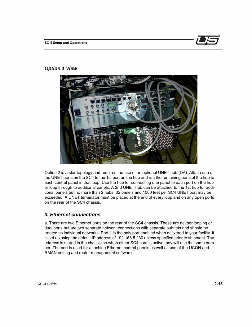
Option 2 is a star topology and requires the use of an optional UNET hub (DA). Attach one of the UNET ports on the SC4 to the 1st port on the hub and run the remaining ports of the hub to each control panel in that loop. Use the hub for connecting one panel to each port on the hub or loop through to additional panels. A 2nd UNET hub can be attached to the 1st hub for addi-tional panels but no more than 2 hubs, 32 panels and 1000 feet per SC4 UNET port may be exceeded. A UNET terminator must be placed at the end of every loop and on any open ports on the rear of the SC4 chassis.
3. Ethernet connections
a. There are two Ethernet ports on the rear of the SC4 chassis. These are neither looping or dual ports but are two separate network connections with separate subnets and should be treated as individual networks. Port 1 is the only port enabled when delivered to your facility. It is set up using the default IP address of 192.168.5.230 unless specified prior to shipment. The address is stored in the chassis so when either SC4 card is active they will use the same num-ber. The port is used for attaching Ethernet control panels as well as use of the UCON and RMAN editing and router management software.

Hardware Installation
2-16 Hardware Installation
b. Connect a standard straight through CAT5 cable to Ethernet port 1 if running to a local hub or a LAN and use a standard crossover cable if running directly to a PC. If another IP address is needed, refer to the end of this section for the proper procedure.
To enable Ethernet port 2, use IP2 instead of IP1 when setting up the IP address.
4. SYNC connections
a. There are three Sync ports on the rear of the SC4 chassis.
As a default, the SC-4 uses sync 1 for vertical interval switching.
The sync ports should be fed with analog black burst signals, either NTSC, PAL, or Tri-Level. Do not connect composite sync or digital SDI or HD-SDI signals to these ports.
Each Sync must be terminated in the daisy chain with a BNC 75Ohm / 1% terminator (Fur-nished by Utah Scientific).

SC-4 Guide 2-17
SC-4 Setup and Operations
5. Party Line Port connections
a. There are 4 individual Party Line ports. There can be up to 128 panels installed overall across the 4 ports.
b. Attach coax cable to any of the 4 ports and connect to desired panel using either of the two ports on the control panel. Then loop from the open port on the control panel to the next panel. The party line ports DO NOT require any termination.
6. Serial Port connections
a. There are 6 nine pin serial port connectors on the rear of the SC4 chassis. These ports are currently enabled to use only the UDI-1B (RCP-1) protocol. These can be used as either RS232 (factory default) or RS422 ports and are selectable by moving the appropriate jumper blocks on the SC4 card. Remove both cards and located on the rear left of the SC4 card the jumpers are labeled port 1- port 6. Move the block to the desired position and re-insert the cards. If these jumper blocks must be moved after power has been applied, follow steps at the end of this chapter for proper removal of SC4 cards.
b. Baud rates are currently hard coded for 2 settings. Ports 1,3 and 5 are set to 38.4k for the baud rate with parity set to 8N1. Ports 2,4 and 6 are set to 19.2k for the baud rate with parity set to 7E2. If a different baud rate and parity are required, refer to the end of this chapter for procedure on how to change serial port settings.
c. Serial ports only use TX, RX and GND for RS232, which are pins 2(TX), 3(RX) and 5(GND). For RS422 the pins are 7(TX+), 8(RX-), 2(TX-) and 3(RX+) If Attaching to a standard 9 pin PC port simply use a straight through 9 pin cable for RS232.

Hardware Installation
2-18 Hardware Installation
Applying Power to SC4 Chassis
1. Plug both AC cords in and verify that the power supplies and SC4 cards power up correctly.
2. The power supplies should come on with only green LED’s on.
3. One of the SC4 cards will come up as the active card and should have the power, SYNC and Ethernet 1 green LED’s on. The amber Ethernet traffic LED will also flicker.
4. The backup card will only have the green power and SYNC LED’s on.
5. The green ready LED will come on, on both cards after the information that is in the active card has been synced up with the backup card. This can take several minutes depending on how much information is stored in the active card.
Changing IP address for SC4 chassis
1. Currently, IP address changes must be done manually using the RJ45 diagnostic port located on the front of the SC4 card.
2. Connect a standard straight through CAT5 cable to the RJ45 connector on the front of the active SC4 card to the 9 pin - RJ45 adapter that was provided with the system.
3. Connect the adapter to the 9 pin serial port on the PC.
4. Using any terminal program such as HyperTerminal or TeraTerm (provided with system disc) set the baud rate to 19200k and the parity to 8N1 with no flow control and then hit the return key on the keyboard. You should then see the prompt \>. This visual sequence is available, by request, in Quicktime and Flash format.
5. To check current settings type chassis (space)-r and hit the return key. To change the IP address type chassis (space)-ip1 (space) (new IP address) and hit the return key. This will put the new IP, gateway and broadcast addresses into the SC4 chassis. This visual sequence is available, by request, in Quicktime and Flash format.
6. After doing this you must push the reset button on both SC4 cards at the same time. (refer to next section on proper resetting of SC4 cards) After the reset process completes on the terminal, type chassis (space)-r and then return to verify new settings.

SC-4 Guide 2-19
SC-4 Setup and Operations
Changing the Chassis ID
1. Currently, chassis ID changes must be done manually using the RJ45 diagnostic port located on the front of the SC4 card.
2. Connect a standard straight through CAT5 cable to the RJ45 connector on the front of the active SC4 card to the 9 pin - RJ45 adapter that was provided with the system.
3. Connect the adapter to the 9 pin serial port on the PC.
4. Using any terminal program such as HyperTerminal or TeraTerm (provided with system disc) set the baud rate to 19200k and the parity to 8N1 with no flow control and then hit the return key on the keyboard. You should then see the prompt \>. This visual sequence is avail-able, by request, in Quicktime and Flash format.
5. To check the current chassis ID, type chassis (space)-r and hit the return key. (This chassis ID is the name that is found in U-CON for the SC-4 icon). To change the chassis ID, type chassis (space)-chid(space)new name. (This name can contain underscores and hyphens, as long as there are no spaces.)
6. After doing this you must push the reset button on both SC4 cards at the same time. (refer to next section on proper resetting of SC4 cards) After the reset process completes on the ter-minal, type chassis(space)-r and then return to verify new settings.

Hardware Installation
2-20 Hardware Installation
Setting the Correct Time and Date
Note: Any date and time set must be completed for both cards in a two card system. Follow this procedure - including ‘Proper Reset’ and ‘Proper Changeover’ whenever the time and date are set. Note also that this setting is independent of your house clock.
1. Currently, date and time changes must be done manually using the RJ45 diagnostic port located on the front of the SC4 card.
2. Connect a standard straight through CAT5 cable to the RJ45 connector on the front of the active SC4 card to the 9 pin - RJ45 adapter that was provided with the system.
3. Connect the adapter to the 9 pin serial port on the PC.
4. Using any terminal program such as HyperTerminal or TeraTerm (provided with system disc) set the baud rate to 19200k and the parity to 8N1 with no flow control and then hit the return key on the keyboard. You should then see the prompt \>. This visual sequence is available, by request, in Quicktime and Flash format.
5. At the prompt, type settime, then press ENTER. This will allow you to designate the current time in the format provided. HH:MM:SS - hours, minutes, and seconds separated by a colon. Press ENTER.
6. Next you will designate the date by typing setdate at the prompt, then press ENTER. Month, day, year, and day of the week are entered, separated by forward slashes. In this case, Wednesday, July 9, 2008 would be entered as:
07/09/08/3 [ENTER]
Days of the week correspond to Monday - 1, to Sunday - 7.
Next you will need to perform a system reset to update the time and date (Proper Reset, next).
Proper Reset
1. If a reset is needed with only one card installed, simply push the reset button on that partic-ular card (outside button).
2. A system reset needed within a two-card system can be accomplished with or without both ready lights on. Locate the active card, press and hold the reset buttons on both cards at the same time. Let go of the reset button on the active card first, followed by the reset button on the backup card. This will ensure that the active card comes up first and remains the active card. Important: An improper reset may cause serious loss of data. (To do next, Proper Changeover.)

SC-4 Guide 2-21
SC-4 Setup and Operations
Proper Changeover
To change over from the active card to the back up card, simply push the change over button on the active card (the inside button). The change over button does not function when pushed on the back-up card.
Proper Hot Swappable Removal of SC4 Cards
1. The SC4 cards are hot swappable so if only one card exists in your system, simply remove the card and re-insert it when ready. Make certain to plug the card in firmly.
2. If there are two cards in your system always make certain there is a ready light on both cards prior to removing the cards. If both cards are to be removed, first remove the backup card (this is the one without the Active LED on) and then remove the active card last.
3. If only the active card is to be removed, make sure the ready light is on both cards and then push the changeover button (inside button) on the active card to switch control to the backup card. Then remove the original active card.

Hardware Installation
2-22 Hardware Installation
Changing Serial Port Settings
There are two ways to modify serial port settings; using the U-CON software (see the U-CON Operations Guide), or manually through the config file within the SC4/SC-400.
Step 1 - Launch the NFS Server.
Step 2 - Navigate to C:/usi/”call letters”-sc401/encode
Step 3 - Run the batch file called getencode.bat, and follow the instructions from each call-out.
Step 4 - A new file called “call letters”-sc401.conf will appear in the encode folder. Open this with the text editor.
Step 5 - Scroll to the bottom of the file and make the desired changes to the serial ports.
Note: When editing this file it is imperative that all spaces and commas remain as they are seen. FAilure to do so will cause the SC-4 to not function properly.
Step 6 - Save changes and exit the file.
Step 7 - Run the batch file called burnenc-network-nr.bat.
FIGURE 2-4. Burn Encode - screen 1

SC-4 Guide 2-23
SC-4 Setup and Operations
FIGURE 2-5. Burn Encode - screen 2
FIGURE 2-6. Burn Encode - screen 3
Hardware Installation
2-24 Hardware Installation
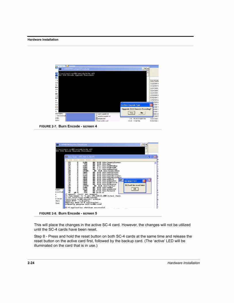
FIGURE 2-7. Burn Encode - screen 4
FIGURE 2-8. Burn Encode - screen 5
This will place the changes in the active SC-4 card. However, the changes will not be utilized until the SC-4 cards have been reset.
Step 8 - Press and hold the reset button on both SC-4 cards at the same time and release the reset button on the active card first, followed by the backup card. (The ‘active’ LED will be illuminated on the card that is in use.)

SC-4 Guide 2-25
SC-4 Setup and Operations
Ethernet LEDs
ENET #1 (Network Interface #1)
Link = should be green when attached to a network. Activity = should flicker amber with activity on the network.
ENET #2 (Network Interface #2)
Link = should be green when attached to a network. Activity = should flicker amber with activity on the network.
System LEDs
ACTIVE = This LED will be green along the active card used on the system, and off along the back-up card.
SMPTE = Not currently implemented.
PS1 FAIL = this will be red when the left power supply fails.
PS2 FAIL = This will be red when the right power supply fails.
READY = This will be green when there are two cards inserted. It will come on at the same time as the ready LED on the back-up card. It indicates that the back-up card reflects the same configuration as the active card.
Sync LEDs
SYNC A = This LED will turn green when a sync source is put into the Sync 1 port on the rear of the chassis. Usable Sync formats include NTSC, PAL, and Tri-Level.
SYNC B = This LED will turn green when a sync source is put into the Sync 2 port on the rear of the chassis. Usable Sync formats include NTSC, PAL, and Tri-Level.
SYNC C = This LED will turn green when a sync source is put into the Sync 3 port on the rear of the chassis. Usable sync formats include NTSC, PAL, and Tri-Level.
Power Supply LEDs
5v FAIL = If the 5 volt supply drops below 5 volts, this LED will turn red.
BAT FAIL = If the battery voltage drops below 3.3 volts, this LED will turn red.

Hardware Installation
2-26 Hardware Installation
1.8v FAIL = If the 1.8 volt supply drops below 1.8 volts, this LED will turn red.
12v FAIL = If the 12 volt supply drops below 12 volts, this LED will turn red.
3.3v FAIL = If the 3.3 volt supply drops below 3.3 volts, this LED will turn red.
POWER OK = If all of the voltages are good, this LED will remain green.

SC-4 Routing and Control System 3-1
CHAPTER 3 System Configuration
In this ChapterSC-4 Control Board System Operation ...........................3-2Redundant Operation ................................................................ 3-2The Debug Port ......................................................................... 3-2
The SC-4 Control Board ..................................................3-3SC-4 Front View Components and Functions ........................... 3-3The SC-4 Control Board Hardware Settings ............................. 3-4Hardware Changes on the SC-4 Control Board ........................ 3-5
SC-4 Control Board Error and Status LED’s ...................3-7Power Supply LED’s .................................................................. 3-7
System LED’s ..................................................................3-9
The SC-4 Monitor Display Operation ..............................3-11Features and Functions of the SC-4 Monitor Display ................ 3-11Monitor Display Formats ............................................................ 3-12
The SC-4 Power - Supply and Connections ...................3-18Voltage Alarms .......................................................................... 3-19SC – 4 Power Supply – Top View .............................................. 3-20
The SMPTE and Remote Alarms ....................................3-21Alarm Port Pin-Outs ................................................................... 3-22Serial Port Pinouts ..................................................................... 3-22

System Configuration
3-2 System Configuration
SC-4 Control Board System Operation
The SC-4 Control System is designed so it may operate with one control board or in the redun-dant mode, with two control boards. Utah Scientific always recommends having the system configured as a redundant system in case of board failure during system operation.
Redundant Operation
When the SC-4 System is powered up the top control board typically comes up in the primary mode. This is not always the case and the user should be aware that either board (upper or lower) would function equally well as the primary controller after the power up sequence.
The Debug Port
The RJ-45 Debug Port is provided on each control board and is located on the front Right-hand side of each board. See Figure 1.
The Debug Port has two primary functions:
1. To aid the user in system diagnostics or when diagnosing problems with Techni-cal Services.
2. When performing software upgrades as recommended by Utah Scientific.
The Debug Port can be connected to a PC using the adapter plug (Part # 140100-2, DB-9S to RJ-45) provided by Utah Scientific and a straight through CAT-5 cable (furnished by the user).
The debug port will communicate with any terminal program although Hyper-terminal and Tera-Term Pro are two of the programs that work well.
The set up for your terminal emulator should be:
1. 19200 Baud,
2. 8 Data Bits,
3. No Parity,
4. 1 Stop Bit,
5. No flow control.

SC-4 Operations Guide 3-3
The SC-4 Control Board
The SC-4 Control Board
This section is devoted to describing only those components, which are user accessible or changeable, in the context of normal operation.
FIGURE 3-1. SC-4 Control Board Components – Front View
SC-4 Front View Components and Functions
The following table describes the components of the front view:
TABLE 3-1. SC-4 Control Board Front View Component Functions
Component Function
L & R Board Extractors Rotate outward to extract board from the chassis.
RJ-45 Debug Port Female connector for RJ-45 Debug Cable.
Chgovr Switch Push to change to inactive SC-4 board.
Reset Switch Push to reset control board – Use with cau-tion, setups may be lost.
RJ-45 Debug Port
Chgovr Switch
Reset Switch
Left Board Extracter Right Board Extracter

System Configuration
3-4 System Configuration
IMPORTANT: Before removing any SC-4 Control Board from the SC-4 Chassis verify and/or do the following:
Using the “CHGOVR” (changeover) switch to deactivate an “ACTIVE” control board:
1. Verify the “READY” LED’s on “Both” control boards are “ON”.
a. The “READY” LED on the inactive board indicates it is in sync with the active board and the configuration tables are current.
Caution: Do not attempt to remove the currently active board until the “READY” LED is “ON” – on the redundant board. If the board is removed with the “READY” LED “OFF” configuration tables could be corrupted and / or destroyed.
2. Verify the “ACTIVE” LED is currently “ON” for the board you wish to change.
a. Press the “CHGOVR” switch (on the Left) and hold it in momentarily until the “Active” LED goes “OFF”, the “READY” LED should still be “ON”.
3. Verify the “READY” and “ACTIVE” LED’s are now “ON” - on the redundant control board.
4. Prepare to remove the control board.
Using the “RESET” switch when removing an “INACTIVE” control board:
1. Press the reset button on the front of the board. This will force the control board to a known state and preserve its configuration integrity.
a. Observe the Power OK LED goes off for approximately one second.
2. Quickly remove the SC-4 Control Board from the chassis.
The SC-4 Control Board Hardware Settings
The following hardware changes must be made with the SC-4 Control Board removed from the chassis. If your system does not have redundant controllers these changes should be made during equipment maintenance downtime.
If your system does have redundant controllers, be sure to make the same changes to both of the controller boards.
Refer to Figure 3-2 to locate the area of the hardware functions you wish to change.

SC-4 Operations Guide 3-5
The SC-4 Control Board
Hardware Changes on the SC-4 Control Board
Note: When making hardware changes on one SC-4 Control Board, be sure that the same changes are made on the other (redundant) SC-4 Control Board.
The changes that can be made on the SC-4 Control Board include the following:
1. Serial Ports – Each Serial Port gang-jumper must be physically moved from the RS-232 (factory default) position to the RS-422 position. It changes the pin-outs for each of the DB-9S connectors on the backplane; it does not affect pro-tocols.
2. VBAT: J-3 -This jumper should always be in the VBAT position so the controller will maintain its configuration data. Moving the VBAT jumper position to the GND position will default the SC-4 Controller. Do not change this jumper unless you are having a configuration problem or Utah Scientific Technical Services advises you to do so.
3. Watchdog - Change J-9 if you wish to enable or disable the watchdog timer.
4. SW-3 - When the SC-4 System is shipped from the factory; these switches are all moved to the “OFF” position. Do not change switch positions unless advised to do so by Utah Scientific Technical Services.

System Configuration
3-6 System Configuration
FIGURE 3-2. SC-4 Control Board – Top View
System Sync Power SupplyENET #1 ENET #2
J-11
Watchdog1 - 2 = Enable2 - 3 = Disable
J-10
SW-38 - Position Dipswitch- All Switches "OFF"
RJ - 45Debug Port
Reset SwitchChgover SwitchError and Status LED's
SDRAM Board
3 Volt Lithium Battery
GN
D
J3
VB
AT
Serial Ports 4, 5 and 6RS-232 / RS-422 Jumper Blocks
Serial Ports 1, 2 and 3RS-232 / RS-422 Jumper Blocks
Moving Jumper to GND DefaultsBattery Backed up RAM
J-9J-8
Note: RS-232 is the factory default setting

SC-4 Operations Guide 3-7
SC-4 Control Board Error and Status LED’s
SC-4 Control Board Error and Status LED’s
The error and status LED’s are located on the very front of the SC-4 Control Board, directly below the SD-Ram board. These LED’s are not viewable with the front cover installed.
If a major voltage fault exists, it will be reflected on the front cover light pipes.
System or Sync error conditions may not be reflected on the front cover light pipes.
Should you suspect an error condition, remove the SC-4 Front Cover and verify if there is a fault on the control board.
If a fault is present contact Utah Scientific Technical Services at 1.800.447.7204.
Power Supply LED’s
The Power Supply LED Group is described below:
TABLE 3-2. Power Supply LED Group Indications
LED Color Status Indication
Power OK Green Off = P.S. Fail
On = Normal
3.3V Fail Red Off = No Fault
On = +3.3 Volts DC Failure
12 V Fail Red Off = No Fault
On = +12 Volts DC Failure
1.8 V Fail Red Off = No Fault
On = +1.8 Volts DC Failure
Power Supply
5V F
AIL
BA
T F
AIL
1.8V
FA
IL
12V
FA
IL
3.3V
FA
IL
PO
WE
R O
K

System Configuration
3-8 System Configuration
* If the system indicates a battery failure, observe the precautions on Page 3-4 before removing the board and checking or replacing the battery. Replacement batteries can be ordered through Utah Scientific Technical Services at 1.800.447.7204.
Batt Fail Red Off = No Fault
On = 3 Volt Lithium Battery Failure
*See note below
5V Fail Red Off = No Fault
On - +5 Volt DC Failure
TABLE 3-2. Power Supply LED Group Indications
LED Color Status Indication

SC-4 Operations Guide 3-9
System LED’s
System LED’s
The System LED Group is described below:
Sync LED’s
The Sync LED Group is described below:
TABLE 3-3. System Status/Warning LED Group Indications
LED Color Status Indication
Ready Green Off = SC-4 not in sync with partner card
On = Active and redundant boards are in sync and configuration data is being updated
PS-2 Fail Red Off = No Fault
On = Left hand power supply failure
PS-1 Fail Red Off = No Fault
On = Right hand power supply failure
SMPTE Alarm Red Off = No fault
On = The SMPTE Alarm is indicating failure
Active Green Off = The SC-4 is in standby or inactive
On = The SC-4 is controlling system activities.
System
AC
TIV
E
SM
PT
E A
LA
RM
PS
-1 F
AIL
PS
-2 F
AIL
RE
AD
Y
Sync
Syn
c A
Syn
c B
Syn
c C

System Configuration
3-10 System Configuration
The Sync A, Sync B and Sync C LED’s indicate there is a valid sync signal present when ON.
When OFF – no sync signal is present.
All LED’s are Green.
ENET #1 and ENET #2 LED’s
The Ethernet LED’s are described below:
The green LINK LED’s, when “ON”, indicate the Ethernet cable is connected and valid Ether-net data is present.
When the LINK LED is “OFF” either the Ethernet cable is unplugged or the network is down or has problems.
The yellow “ACTIVITY” LED’s “Flash” to indicate data is transferring across the Ethernet.
SW3 – Switch 3 Description
The picture for SW3 is presented here so the user can identify the switch and each switch location as it is silk-screened on the SC-4 Control Board. Currently there are no user-defined functions for SW3. All of the switches will be in the “OFF” position on all controllers in the SC-4 Control Systems currently being shipped from the factory.
FIGURE 3-3. SW3 Identification – Viewed from the Top Rear of the SC-4
ENET #1
LIN
K
AC
TIV
ITY
ENET #2
LIN
K
AC
TIV
ITY
11 2 3 4 50
USER SWITCH
BY
PA
SS
ON
SW
3
1 2 3 4 5 6 7 8
ON

SC-4 Operations Guide 3-11
The SC-4 Monitor Display Operation
The SC-4 Monitor Display Operation
Note: This is considered a back-up method for changing the IP address. Please see “Changing IP address for SC4 chassis” on page 2-18 for the preferred process.
The SC-4 Monitor Display is located on the front - bottom center of the SC-4 Chassis. The clear plastic lens on the front cover allows the user to view the selected status with the cover on.
Currently the only displays available are Time, Date, the Name assigned the SC-4 Chassis and the Network Setup Menu.
Figure 3-4, below, identifies the main features of the SC-4 Monitor Display Board:
FIGURE 3-4. Monitor Display Features
Features and Functions of the SC-4 Monitor Display• 24 Character Alphanumeric Display: 5 x 7 green dot matrix.
• Display Scroll Button – Up: scrolls the displays up or when in edit mode sequences characters / numbers up.
• Display Scroll Button – Down: scrolls the displays down or when in edit sequences characters / numbers down.
• Display Edit Button:
1. Pressing this button once enters into the edit mode for the current display.
2. Each press of the button thereafter moves the cursor one digit to the right from its starting point to select the characters or numbers to be edited.
Alphanumeric Display - 24 Character
Display Edit Control Button
Display Scroll Button - Down
Display Scroll Button - Up

System Configuration
3-12 System Configuration
3. Pressing and holding the button in momentarily activates the “Save” prompt for the display being edited.
a. Press the Scroll Up button to “Save”.
b. Press the Scroll Down button to ignore or not save any changes.
Monitor Display Formats
The formats for each display are fixed so the user can only change specific characters / num-bers in each display.
As you scroll DOWN through the formats starting with Time: the formats displayed are:
• Time
• Date
• Name
• Network Setup Menu
Network Setup Submenus: (scrolling down)
1. IP Addr1: 7. IP Addr2:
2. IP Mask1: 8. IP Mask2:
3. Brdcast1: 9. Brdcast2:
4. RouteIP1: 10. RouteIP2:
5. Routmsk1: 11. Routmsk2:
6. Gateway1: 12. Gateway2:
Note: Submenus 1 – 6 apply to Ethernet Port 1; Submenus 7 – 12 apply to Ethernet Port 2.

SC-4 Operations Guide 3-13
The SC-4 Monitor Display Operation
Character Set
After you select a format to edit, Table 4 shows the character set available to you. The charac-ter set may be scrolled up or down to select the character or number you need to fill the edit-able blocks.
The number (#) on the left of each character indicates the characters sequence number as it is being scrolled down from the top starting with the space and ending with the character “Z”. There are no lower case characters in this character set.
TABLE 3-4.
# Character # Character # Character # Character
1 Space 16 (forward slash)
/
31 > 46 M
2 ! 17 0 32 ? 47 N
3 - 18 1 33 @ 48 O
4 # 19 2 34 A 49 P
5 $ 20 3 35 B 50 Q
6 % 21 4 36 C 51 R
7 & 22 5 37 D 52 S
8 ‘(quote) 23 6 38 E 53 T
9 ( 24 7 39 F 54 U
10 ) 25 8 40 G 55 V
11 * 26 9 41 H 56 W
12 + 27 : (comma) 42 I 57 X
13 , (comma) 28 ; (semicolon) 43 J 58 Y
14 - 29 < 44 K 59 Z
15 . (period) 30 = (equal) 45 L

System Configuration
3-14 System Configuration
Time Format:
The display of the time is shown in Figure 3-5, below, indicating which characters may be edited in the display.
FIGURE 3-5. Time Display Edit Parameters
Date Display Format:
The portions of the Date Display that can be edited are shown in Figure 3-6 below.
FIGURE 3-6. Date Display Edit Parameters
Name Display Format:
The edit portions of the Name Display are shown in Figure 3-7, below:
FIGURE 3-7. Name Display Edit Parameters
In Time Display ONLY These Parameters can be changed
In Date Display ONLY These Parameters can be changed
In Name Display ONLY The "NAME:" can't be changed.Nineteen characters or numbers may be entered.
In "Edit" mode these blocks indicate SPACES (that can be edited).

SC-4 Operations Guide 3-15
The SC-4 Monitor Display Operation
Network Setup Menu
To enter into the Network Setup Menu first scroll down to the Network Setup Menu Display. It will appear as shown in Figure 3-8.
This display cannot be edited.
FIGURE 3-8. Network Setup Menu Display
Network Setup Submenus
In the IP Address 1 Submenu only the items can be changed shown in Figure 3-9:
FIGURE 3-9. Submenu-1; IP Address 1
The IP Mask 1 Submenu items that can be changed are shown in Figure 3-10:
FIGURE 3-10. Submenu-2; IP Mask 1
In Network Setup Submenu - 1: ONLY These Parameters can be changed
In Network Setup Submenu - 2: ONLY These Parameters can be changed

System Configuration
3-16 System Configuration
The Brdcast 1 Submenu items that can be changed are shown in Figure 3-11:
FIGURE 3-11. Submenu-3; Broadcast 1 Address
The ROUTEIP 1 Submenu items that can be changed are shown in Figure 3-12:
FIGURE 3-12. Submenu-4: Route IP Address 1 Address
The ROUTMSK 1 Submenu items that can be changed are shown in Figure 3-13:
FIGURE 3-13. Submenu-5; Route Mask 1 Address
The Gateway 1 Submenu items that can be changed are shown in Figure 3-14:
FIGURE 3-14. Submenu 6; Gateway 1 Address
In Network Setup Submenu - 3: ONLY These Parameters can be changed
In Network Setup Submenu - 4: ONLY These Parameters can be changed
In Network Setup Submenu - 5: ONLY These Parameters can be changed
In Network Setup Submenu - 6: ONLY These Parameters can be changed

SC-4 Operations Guide 3-17
The SC-4 Monitor Display Operation
Submenus 7 through 12 include the same items and formats with the exception that each of the menu items are suffixed with a “2”.
An IP Address entry as shown below will turn off the Ethernet Interface and that port will not be active.
Note: Each network address is applied to the chassis backplane, the Date and Time is loaded into the SC-4 Control Board. When Date and Time are changed it must be changed on both control boards.
Back to Main Menu:
Once all of the Network Setup Screens have been scrolled through and edited, the Back to Main Menu Screen appears. To go back to the main menu press the Display Edit Button “Once”, the Network Setup Menu Screen will again be displayed.
FIGURE 3-15. End Display of Network Setup Menu.
At the end of the Network Setup Submenu this screen will be displayed - noparameters can be changed in this display.

System Configuration
3-18 System Configuration
The SC-4 Power - Supply and Connections
The power supply furnished with each SC-4 Control System utilizes auto-selectable (117 VAC / 234 VAC) switching power supplies. Each supply is capable of powering a fully loaded sys-tem by itself. Utah Scientific recommends redundant supplies as standard because redundant supplies share the load equally, which increases the total serviceable life of each supply.
Figure 16, Figure 17 and Table 5 identify and explain the features of the SC-4 Power Supply as viewed from the Front.
Note: The Left and Right Power Supplies are identical, when inserted into the chassis the air vents must align with the outside edge of the chassis. For example, if the Right Hand Supply is relocated to the Left, it must be rotated 180 degrees for proper insertion.
FIGURE 3-16. Left and Right Power Supplies
FIGURE 3-17. Front View of the SC-4 Power Supply Features
PS Alarm
+5
+3.3
+12
-12
TMP
FAN
PS Alarm
+5
+3.3
+12
-12
TMP
FAN
Left Power Supply Right Power Supply
Power Supplies are inserted upside down from each other.
PS Alarm
+5
+3.3
+12
-12
TMP
FAN
Power Supply Extractor Handle
Green / Red Main Power Supply Status LED
Red Fan Alarm LED
Red Temperature Alarm LED
Red -12.0 Volt DC Alarm LED
Red +12.0 Volt DC Alarm LED
Red +3.3 Volt DC Alarm LED
Red +5.0 Volt DC Alarm LED
Air Vents
Silk Screened LED Identification Plate (Part of Chassis)
SC-4 Power Supply Features Identification (Front View)

SC-4 Operations Guide 3-19
The SC-4 Power - Supply and Connections
Voltage Alarms
Any voltage failures on the SC-4 Power Supply are also detected on the SC-4 Control Boards. For example, a 5 Volt DC failure occurring on the right hand power supply would cause the PS-1 Fail and SMPTE Alarm LED’s to turn on the control board.
Removal of the defective power supply or correction of the problem should remove all SC-4 Control Board errors.
TABLE 3-5. SC-4 Power Supply LED Functions
LED Color Function
PS Alarm
Normal = Green
Fault = Red
Turns “RED” if any faults on the power supply are detected. The SMPTE Alarm
is also activated.
Fan Normal = Off
Fault = Red
Indicates a Fan Failure, either the fan has seized up or rotation is not being
detected.
Tmp Normal = Off
Fault = Red
Indicates the power supply is overheat-ing. Check the fan, or air vent obstruc-
tions.
-12 Normal = Off
Fault = Red
Indicates the -12 volts DC has failed in the supply.
+12 Normal = Off
Fault = Red
Indicates the +12 volts DC has failed in the supply.
+3.3 Normal = Off
Fault = Red
Indicates the +3.3 volts DC has failed in the supply.
+5 Normal = Off
Fault = Red
Indicates the +5 volts DC has failed in the supply.

System Configuration
3-20 System Configuration
SC – 4 Power Supply – Top View
When the SC-4 Power Supply is removed from the chassis you will see the components indi-cated in Figure 3-18.
Note: None of the components shown are user serviceable. Contact Utah Scientific for a replacement supply if it is failing.
FIGURE 3-18. SC-4 Power Supply – Top View
Power Supply ModuleFan
12 VDC0.140 A
J1
P. S. Interface Board
SC-4 Power Supply Components (Top View)
FR
ON
T

SC-4 Operations Guide 3-21
The SMPTE and Remote Alarms
The SMPTE and Remote Alarms
The SC-4 Control System has two SMPTE Alarm circuits and four Remote Alarm circuits. The features and/or functions of each alarm is shown in Table 6, below; the DB-9S Alarm Back-plane Connector is shown in Figure 19.
FIGURE 3-19. DB-9 Alarm Port Connectors
TABLE 3-6.
Alarm Specification Function
SMPTE 0 SMPTE 269M-1999 Standard relay closure fault reporting
SMPTE 1 SMPTE 269M-1999 Standard relay closure fault reporting
Alarm 0 N/A TTL Logic, 5 Volts @ 5 milliamps
Alarm 1 N/A TTL Logic, 5 Volts @ 5 milliamps
Alarm 2 N/A TTL Logic, 5 Volts @ 5 milliamps
Alarm 3 N/A TTL Logic, 5 Volts @ 5 milliamps
DB-9P (MALE on Cable)
1 2 3 4 5
6 7 8 9
DB-9S (FEMALE on Chassis)
12345
6789

System Configuration
3-22 System Configuration
Alarm Port Pin-Outs
Table 3-7 shows the Alarm Port Pin-Outs for the DB-9 Connector.
Serial Port Pinouts
TABLE 3-8.
TABLE 3-7.
Connector Pin Signal
1 ALM0
2 ALM1
3 ALM2
4 ALM3
5 SMPTE0
9 SMPTE1
6, 7, 8 GND
RS-232 Mode RS-422 Mode
1 RI 1 Not used
2 TXD 2 TX-
3 RXD 3 RX+
4 DSR 4 Not used
5 Ground 5 Ground
6 DTR 6 Not used
7 CTS 7 TX+
8 RTS 8 RX-
9 CD 9 Not used
DB-9P (MALE on Cable)
1 2 3 4 5
6 7 8 9
DB-9S (FEMALE on Chassis)
12345
6789

SC-4 Operations Guide 3-23
The SMPTE and Remote Alarms

System Configuration
3-24 System Configuration

SC-4 Routing and Control System 4-1
CHAPTER 4 Operations
In this ChapterSC4 Operations ........................................................4-2The Debug Port .................................................................. 4-2Physical Connection ........................................................... 4-2Terminal Emulation software setup .................................... 4-2General Status ................................................................... 4-2Specific Operations ............................................................ 4-3Shutting down the SC4 application .................................... 4-4Resetting the SC4 ..............................................................4-4Gathering data from the onboard log ................................. 4-5

Operations
4-2 Operations
SC4 Operations
The Debug Port
Introduction
The debug port of the SC4 is the major source of operational information and control. While configuration info is downloaded to the SC4 via UCON, some operational information is still best determined by a direct connection to the debug port.
Physical Connection
Supplied with your SC4 is an adapter intended to plug on to the serial port of any standard PC. This adapter is USI PN 140100-2. It has a male 9 pin D connector on one end and a female RJ-45 connector on the other. The user supplies a straight thru CAT 5 cable between the adapter and the debug port on the SC4 (see figure 3-1 in this manual for location).
Terminal Emulation software setup
Any terminal emulation program such as windows Hyper terminal is useful for debug port oper-ation. Utah Scientific recommends TeraTerm, a freeware terminal emulation software package available on the internet. Serial Port parameters necessary to communicate to the SC4 are as follows:
General Status
Once you are connected to the SC4, pressing the return key should return a prompt of “/>”. From this prompt various operations can be performed.
TABLE 4-1.
Baud Rate 19.2K
Data Bits 8
Stop Bits 1
Parity NONE
Hardware Handshaking NONE

SC-4 User’s Guide 4-3
SC4 Operations
The most valuable data is gathered after a system reset. This is the point where the SC4 ‘finds’ all connected routers and control panels. The best method for determining what the SC4 discovers is to connect the debug port to the upper SC4 and then press and release the reset buttons (See figure 3-1) simultaneously. After several screens of data that deal with the bootup process, you will see messages such as the following:
MX H/W found: input 0, output 0, level 0, id 0x40
configServer: register PL panel 3, name CSP-500, model CSP-16160
MX H/W messages indicate that the SC4 has found and MX-Bus based router at the specified address. The ID number varies with different address types.
configServer messages indicate panel types and address found.
Specific Operations
Reading system setup information
The chassis command is used to read and/or set the chassis IP address(s), system name and other parameters. It’s usage is detailed below.
chassis
Synopsis: chassis [OPTIONS] [FILE]
This program allows the user to interact with the chassis identification ROM located in the local chassis. Not all new USI products support this feature. If you aren’t sure or are getting unexpected results, please check the appendix and verify the operation is supported on the platform you are working with.
Options:
• -h – displays the help information
• -d – activates debug mode which displays low level interactions with the device hardware.
• -r – read and display data contained in the local chassis config ROM.
• -init – write a set of default values into the chassis config ROM

Operations
4-4 Operations
• -ip1 <xxx.xxx.xxx.xxx> – sets the IP address for network interface 1 to the specified value.
• -ip1 <xxx.xxx.xxx.xxx> network <xxx.xxx.xxx.xxx> optionally sets subnet mask
• -ip2 <xxx.xxx.xxx.xxx> – sets the IP address for network interface 2 to the specified value.
• Please note not all devices support a 2nd network interface.
• ip2 <xxx.xxx.xxx.xxx> netmask <xxx.xxx.xxx.xxx> - optionally sets subnet mask
• -cust <customer name> - Sets the customer name to the text specified. Typically this will be the call letters of the station using the device.
• -chid <chassis ID> - This sets the chassis ID to the text specified. Typically this will be a description of the physical device location. Ex: MCP-CR01-KUSI
• -unet <xxx> - set the unet node for this device to that specified.
• mask1 <xxx.xxx.xxx.xxx> - sets subnet mask for network interface 1 to...
• mask2 <xxx.xxx.xxx.xxx> - sets subnet mask for network interface 2 to...
Shutting down the SC4 application
The sc4down command will turn off the SC4 application. This command might be used prior to reprogramming the SC4’s main image.
sc4down
Synopsis: sc4down
This command sends a signal to all active SC-4 processes and tells them to shutdown. This replaces the need to perform a <ps> command followed by a kill –INT <pid> command which is the method for stopping the current SC-4 software from running. A message will tell the user whether the shutdown has been successful or not.
Resetting the SC4
sc4reset
Synopsis: sc4reset
This command resets the SC-4 board being accessed. When this action is performed on an active board in a redundant system, control will switch over to the other board.

SC-4 User’s Guide 4-5
SC4 Operations
Gathering data from the onboard log
logdump
Synopsis: logdump [OPTIONS]
This command displays log entries from NVRAM. If no option is specified then ALL log entries will be dumped to the screen. Optionally, a number can follow the command, which specifies that only that number of final entries will be displayed. The log can only handle a certain num-ber of entries. Older entries will be lost as the log overflows saving only the most recent events.
Example:logdump 10 - dumps the last ten log messages to the screen
Viewing / Setting Configuration parameters
sc4config is used to display and in some cases modify the custom configuration parameters of the SC4. Various options are detailed below.
sc4config
sc4config display – displays all config tables
sc4config sim – Turns on simulation for all router levels. Append a level number to simulate that level
sc4config nosim – Turns off simulation for all router levels. Append a level num-ber to unsimulate that level
sc4config mx – Displays MX Bus configuration
sc4config pl – Displays Party Line Configuration
sc4config routers – Displays router configuration
sc4config levels – Displays level mapping
sc4config srcs – Displays source table
sc4config dsts – Displays destination table
sc4config serial – Displays serial port parameters
sc4config misc – Displays miscellanous parameters
sc4config dstattrs – Displays router attribute status

Operations
4-6 Operations
tiedump
Displays the tieline status
tiedump clear – clears out the tieline status (crosspoints are not affected.) This will free all tie lines.
lockdump
This displays the output lock status.
lockdump – displays lock status.
lockdump clear – removes all locks.
router
This utility provides certain router status functionality such as setting, viewing, and saving status.
• router xy - This connects each source to its corresponding destination; i.e., 0-0, 1-1, etc. This is best used with the SC-4 default configuration.
• router source <srcnum> - This routes the source value specified as srcnum to all outputs. This is best used with the SC-4 default configuration.
• router killstatus - This clears all router and tieline status (except for attributes) but leaves the SC-4 configuration intact.
• router save display - provides a display of all routes that have occured.
The router utility can also save the router status to a file that can be subsequently loaded. This functionality is best used with the rtrsave and rtrload scripts, found in the SC-4 installation directory; i.e., C:\usi\<cust> - sc401\updates.
Simply double-click the rtrsave.bat file after running the NFS server, then enter the PC IP address and the SC-4 IP address as prompted. You will also be prompted to enter a filename where the current router status will be stored. You may then enter a list of destinations whose status you want to Sav. (Leave this blank to default to all destinations.)
The destination list should look something like this:
1-5,7,11,300-350 (no spaces)
Other destinations will not have their status saved in the file, so a load operation using that file will not affect them. Double-click the rtrload.bat file to load one of the saved files. The router connections will be restored to the saved status.

SC-4 User’s Guide 4-7
SC4 Operations
chassis
This utility provides various chassis commands for modifying the IP address, gateway, mask addresses, chassis ID, and viewing all settings.
FIGURE 4-1. Chassis terminal display

Operations
4-8 Operations

Addendum - Audio Attributes A-1
APPENDIX A Audio Attributes Notice
Important Note
The following information is presented in response to ongoing issues concerning SC-4 attributes. It is critical to note that the 'router killstatus' command will clear status and tielines, but not audio attributes. To clear the audio attributes, you will need to follow the getencode/burnencode procedure detailed within this section.
A 'router killstatus' command can be carried out on later versions of the SC-4 code, which will clear all status, including attributes and tielines. Use 'sc4config dstattrs' to view the current attribute status. If you are using an earlier version of the SC-4 code (or if you only want to clear out the attribute status), complete a ‘getencode' operation, delete the attribute status, then complete a 'burnencode' operation.
See the example on the following pages:

Audio Attributes Notice
A-2 Audio Attributes
###########################################################################
# Destination Device Attribute Table
#
# Audio attrs: 0 Normal, 1 Swap, 2 Mix, 3 MonoLeft, 4 MonoRight, 5 InvLeft,
# 6 InvRight, 7 MuteLeft, 8 MuteRight, 9 Mute
#
# Dig. video attrs: 10 Rate143, 11 Rate177, 12 Rate270, 13 Rate360
#
# Data attrs: 0 Tributary devices, 1 Controller devices, 2 Auto devices
#
# Note: A value of -1 means router default.
#
[PHYS_DST_ATTR_TABLE]
# L 1 L 2 L 3 L 4 L 5 L 6 L 7 L 8 L 9 L10
# INDEX ATTR ATTR ATTR ATTR ATTR ATTR ATTR ATTR ATTR ATTR
227, -1, 4, 4, -1, -1, -1, -1, -1, 4, 4
228, -1, 4, 4, -1, -1, -1, -1, -1, 4, 4
229, -1, 4, 4, -1, -1, -1, -1, -1, 4, 4
230, -1, 4, 4, -1, -1, -1, -1, -1, 4, 4
You can delete the status and leave the file as follows:
###########################################################################
# Destination Device Attribute Table
#
# Audio attrs: 0 Normal, 1 Swap, 2 Mix, 3 MonoLeft, 4 MonoRight, 5 InvLeft,
# 6 InvRight, 7 MuteLeft, 8 MuteRight, 9 Mute
#

SC-4 User’s Guide A-3
# Dig. video attrs: 10 Rate143, 11 Rate177, 12 Rate270, 13 Rate360
#
# Data attrs: 0 Tributary devices, 1 Controller devices, 2 Auto devices
#
# Note: A value of -1 means router default.
#
[PHYS_DST_ATTR_TABLE]
If you want to clear the status out, do NOT delete the [PHYS_DST_ATTR_TABLE] tag. Just delete the status. The status will be cleared when you do a 'burnencode'.
Caution: As you may be already aware, a reset done immediately after a burn encode (on a redundant system) will cause the slave board to take over and rewrite the status to both cards.

Audio Attributes Notice
A-4 Audio Attributes

Introduction B-1
APPENDIX B System Timing Consideration
Overview
This appendix addresses a timing issue that can affect certain system configurations, causing switches to occur out of sync.
The following illustration contains an explanation of HD and SD line switch-ing, and in particular, where the switching should occur.

System Timing Consideration
B-2 Introduction
Switching Example
This is an example of PAL switching. It should be noted that NTSC switching follows suit.
FIGURE B-1. PAL Sync

SC-4 Control System B-3
Overview
The Critical Issue
The SC-4 uses an analog signal (black burst or tri-level) as reference for vertical interval switching. If single sync is used (i.e., black burst), the following should be noted:
Within NTSC configurations, the system is attempting to switch on line 10 of reference, yet within HD/SD environments, the switching of HD signals should occur at line 7. See Figure B-2, “Line Switching,” on page 4.
If these line positions are all timed or synced on line 1 (as displayed in the following Figure), the line 10 [switch] will cause the HD signal to switch late (at line 21 approximately in HD) and therefore out of sync.
PAL-specific HD/SD systems will make the switch at (black burst) line 6, while 1080i systems will execute the switch at line 7. If the rows are lined up along line 1(see illustration), the switch would occur at line 11, resulting in a switch at the incorrect location.
Potential Alternatives
The sync of one format can be offset, allowing the switch to drift back in relationship to the HD. If HD signal devices are referenced to tri-level, that reference can be offset for the black burst reference to bring the different format switching lines [in line]. In particular, you can force the HD line 10 to line up with black burst line 7.
The top line on the chart represents the correct adjustment. This line has shifted back so that line 1 does not line up anymore – however, the lines in the other rows (below in chart) are cor-rectly lining up.
This represents one potential solution. However this is not satisfactory in all cases as an acceptable timing adjustment. Many operational situations require the router as a means for handling this adjustment. The SC-4 does in fact support multiple syncs.
A user can assign each individual router output device to one of the three sync inputs.
Note: Sync port assignment using U-CON must be completed by modifying the batch files. See the System Installation Guide, Appendix B, for more informa-tion.
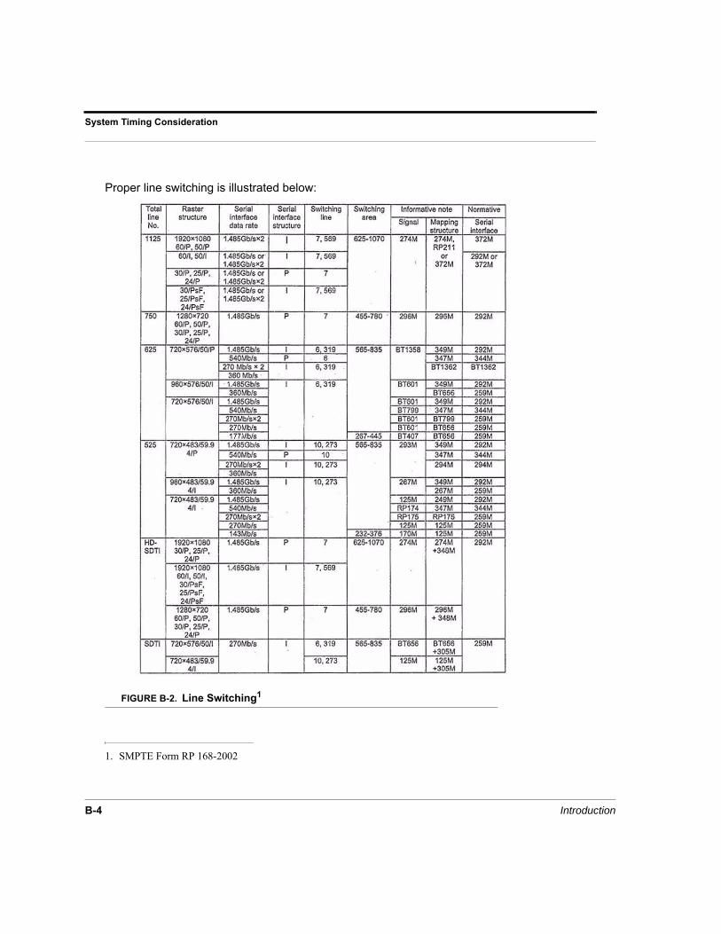
System Timing Consideration
B-4 Introduction
Proper line switching is illustrated below:
FIGURE B-2. Line Switching1
1. SMPTE Form RP 168-2002

SC-4 Control System B-5
Overview
It should be noted that if you are using two formats through the router with just a single sync reference, you will need to adjust your timing between the two signals in order to line up switching points.
Again the solution is to offset the timing as described so that the switch properly occurs on sync, and on the correct line.
Also refer to ‘multiple sync domain’.

System Timing Consideration
B-6 Introduction

SC-4 Setup and Operations Guide i
Index
Numerics0V 2-1012 AWG 2-10-48V 2-10
AAC Plug 1-8AC Power Connections 2-9Air Vents 1-6Alarm 1-8Alarm Port
pin-outs 3-22Alarms Port 2-11Audio Attributes A-1, B-1
BBackplane 1-7Backplane callouts 1-7Backplane Connections 1-8Baud Rate 4-2
CCable connecting 2-6Cable Considerations 2-11Carrier claims 2-5Character Set 3-13Chassis 1-7Chgovr Switch 3-3Clear Display Lens 1-6Components 1-5Configuration parameters 4-5
viewing and setting 4-5Connecting Power 2-8, 2-10Connecting serial ports 2-7Connecting sync ports 2-7Control Board Components 3-3Control Boards 1-7
DData Bits 4-2Date Display Format 3-14Debug Port 3-2, 4-2Display Board 1-7
EEquipment installation 2-6
Ethernet 1-8
FFabricating cables 2-11Front Cover Features 1-5
GGateway 1 3-16getencode/burnencode A-1GPIO 1-8GPIO Ports 2-11Ground 2-10
HHardware Features 1-5Hardware Handshaking 4-2Hardware Installation 2-1Hardware installation 2-6Hardware Requirements 1-4
IInspection 2-2Internal Components 1-7IP Address 1 3-15IP Mask 1 3-15
LL & R Board Extractors 3-3LED’s
ENET #1 and #2 3-10lockdump 4-6lockdump clear 4-6logdump 4-5
MMonitor 1-7Monitor Display Features 3-11Monitor Display Formats 3-12MX-Bus Cable 2-11
NName Display Format 3-14Network Setup Menu 3-15Network Setup Submenus 3-15
OOrdering cables 2-11

ii Index
PPackaging contents 2-3PAL Sync B-2Party Line 1-8Party Line Ports 2-11Power connecting 2-8Power Supplies
views 3-18Power Supply 1-6
features 3-18LED functions 3-19
Power Supply LED’s 3-7
RRedundant Operation 3-2Release Latch 1-6Remote alarm 3-21Reset Switch 3-3Resetting the SC4 4-4RJ-45 Debug Port 3-3ROUTEIP 1 3-16router 4-6router killstatus 4-6, A-1router source 4-6router xy 4-6, 4-7ROUTMSK 1 3-16
SSC- 4 Control System 1-7SC-4
monitor display operation 3-11power supply 3-18
SC-4 Backplane 1-7SC-4 Control Board 3-2, 3-3
error and status LED’s 3-7hardware changes 3-5hardware settings 3-4top view 3-6
SC-4 Front View 3-3SC-4 Options 4-3sc4config 4-5sc4config dstattrs A-1sc4reset 4-4Serial 1-8Serial Port connecting 2-7Serial Port Pinouts 3-22Serial Ports 2-11, 3-5Shipping 1-5Shutting down 4-4
SMPTE alarm 3-21Specific Operations
SC-4 4-3Stop Bits 4-2SW-3 3-5Switch 3 3-10Switching Example B-2Sync 1-8Sync LED’s 3-9Sync Port connecting 2-7System Configuration 3-1System LED’s 3-9System Operations 4-1System power connecting 2-8System Timing B-1
Tterminal block 2-10Terminal Emulation software 4-2tiedump 4-6tiedump clear 4-6Time Format 3-14
UUNET 1-8Unpacking 2-2
VVBAT 3-5Voltage Alarms 3-19
WWarning LED’s 3-9Warnings and Cautions 2-4Watchdog 3-5