Embed Size (px)
Citation preview
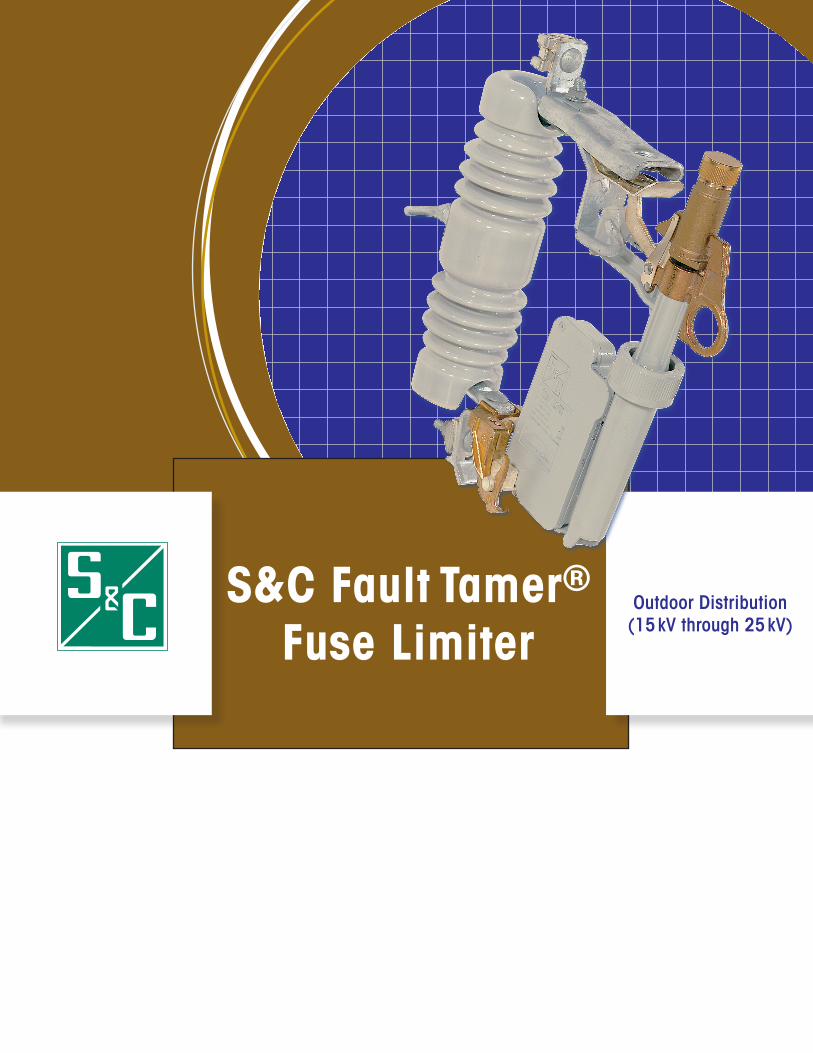
S&C Fault Tamer® Fuse Limiter
Outdoor Distribution (15 kV through 25 kV)
2
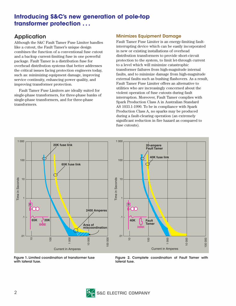
ApplicationAlthough the S&C Fault Tamer Fuse Limiter handles like a cutout, the Fault Tamer’s unique design combines the function of a conventional fuse cutout and a backup current-limiting fuse in one powerful package. Fault Tamer is a distribution fuse for overhead distribution systems that better addresses the critical issues facing protection engineers today, such as: minimizing equipment damage, improving service continuity, enhancing power quality, and improving transformer protection.
Fault Tamer Fuse Limiters are ideally suited for single-phase transformers, for three-phase banks of single-phase transformers, and for three-phase transformers.
Minimizes Equipment DamageFault Tamer Fuse Limiter is an energy-limiting fault-interrupting device which can be easily incorporated in new or existing installations of overhead distribution transformers to provide short-circuit protection to the system, to limit let-through current to a level which will minimize catastrophic transformer failures from high-magnitude internal faults, and to minimize damage from high-magnitude external faults such as bushing flashovers. As a result, Fault Tamer Fuse Limiter offers an alternative to utilities who are increasingly concerned about the violent operation of fuse cutouts during fault interruption. Moreover, Fault Tamer complies with Spark Production Class A in Australian Standard AS 1033.1-1990. To be in compliance with Spark Production Class A, no sparks may be produced during a fault-clearing operation (an extremely significant reduction in fire hazard as compared to fuse cutouts).
Introducing S&C’s new generation of pole-top transformer protection . . .
Figure 1. Limited coordination of transformer fusewith lateral fuse.
Figure 2. Complete coordination of Fault Tamer with lateral fuse.
1 000
100
10
1
.1
.01
10 100
1 00
0
10 0
00
100
000
Tim
e in
Sec
onds
20K fuse link
65K fuse link
2400 Amperes
Area of miscoordination
B
65K 20K
1 000
100
10
1
.1
.01
10 100
1 00
0
10 0
00
100
000
Tim
e in
Sec
onds
Current in Amperes
B
40K FaultTamer
20-ampere Fault Tamer
40K fuse link
Current in Amperes
3
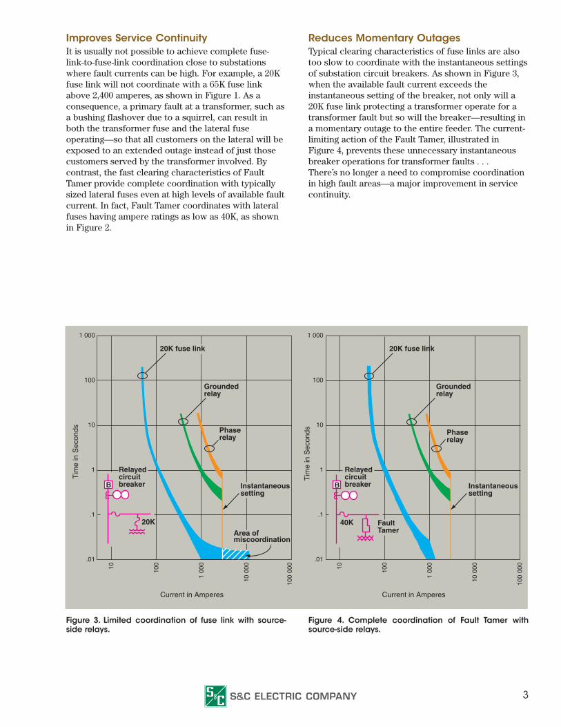
Improves Service ContinuityIt is usually not possible to achieve complete fuse-link-to-fuse-link coordination close to substations where fault currents can be high. For example, a 20K fuse link will not coordinate with a 65K fuse link above 2,400 amperes, as shown in Figure 1. As a consequence, a primary fault at a transformer, such as a bushing flashover due to a squirrel, can result in both the transformer fuse and the lateral fuse operating—so that all customers on the lateral will be exposed to an extended outage instead of just those customers served by the transformer involved. By contrast, the fast clearing characteristics of Fault Tamer provide complete coordination with typically sized lateral fuses even at high levels of available fault current. In fact, Fault Tamer coordinates with lateral fuses having ampere ratings as low as 40K, as shown in Figure 2.
Reduces Momentary OutagesTypical clearing characteristics of fuse links are also too slow to coordinate with the instantaneous settings of substation circuit breakers. As shown in Figure 3, when the available fault current exceeds the instantaneous setting of the breaker, not only will a 20K fuse link protecting a transformer operate for a transformer fault but so will the breaker—resulting in a momentary outage to the entire feeder. The current-limiting action of the Fault Tamer, illustrated in Figure 4, prevents these unnecessary instantaneous breaker operations for transformer faults . . . There’s no longer a need to compromise coordination in high fault areas—a major improvement in service continuity.
Figure 3. Limited coordination of fuse link with source-side relays.
Figure 4. Complete coordination of Fault Tamer with source-side relays.
1 000
100
10
1
.1
.01
10 100
1 00
0
10 0
00
100
000
20K fuse link
Grounded relay
Relayedcircuitbreaker
Phase relay
Instantaneous setting
Area of miscoordination
B
20K
Relayedcircuitbreaker
20K fuse link
Grounded relay
Phase relay
Instantaneous setting
1 000
100
10
1
.1
.01
10 100
1 00
0
10 0
00
100
000
B
40K FaultTamer
Current in Amperes Current in Amperes
Tim
e in
Sec
onds
Tim
e in
Sec
onds
4
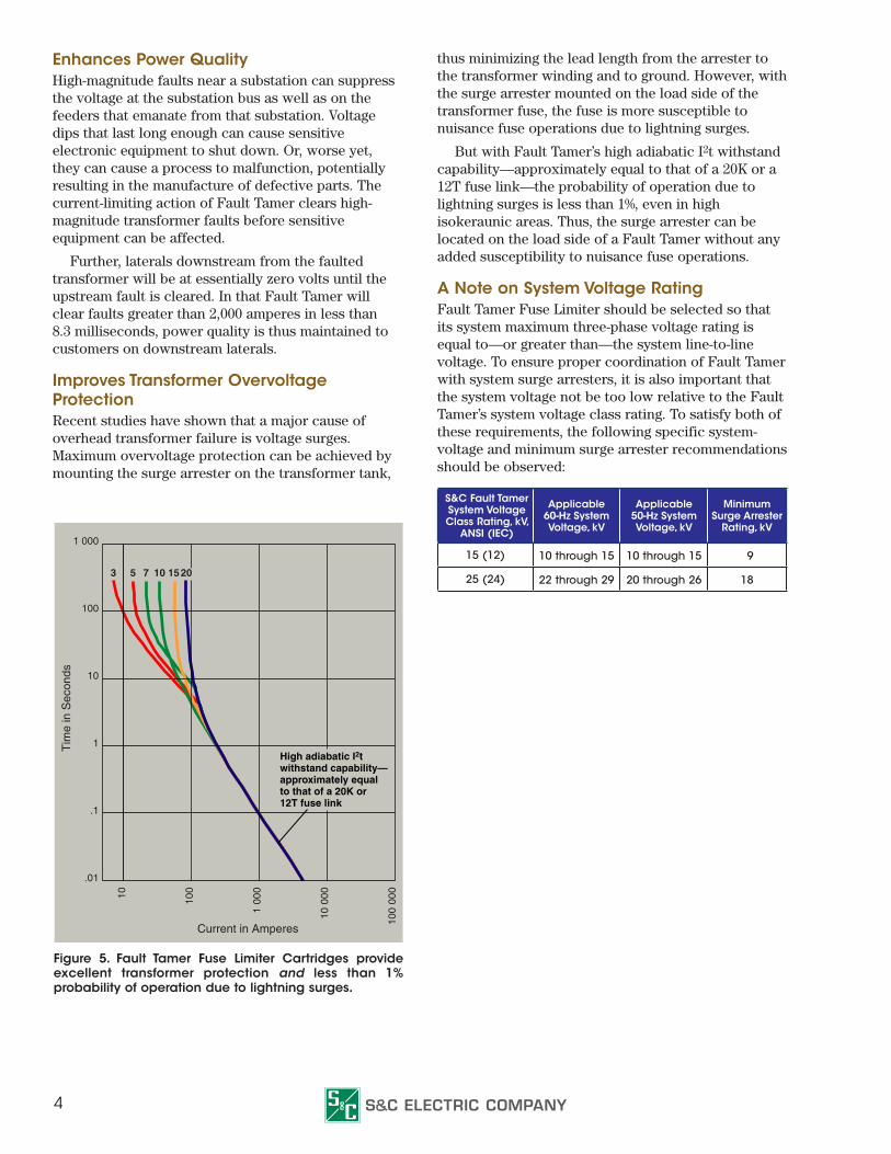
Figure 5. Fault Tamer Fuse Limiter Cartridges provide excellent transformer protection and less than 1% probability of operation due to lightning surges.
Enhances Power QualityHigh-magnitude faults near a substation can suppress the voltage at the substation bus as well as on the feeders that emanate from that substation. Voltage dips that last long enough can cause sensitive electronic equipment to shut down. Or, worse yet, they can cause a process to malfunction, potentially resulting in the manufacture of defective parts. The current-limiting action of Fault Tamer clears high-magnitude transformer faults before sensitive equipment can be affected.
Further, laterals downstream from the faulted transformer will be at essentially zero volts until the upstream fault is cleared. In that Fault Tamer will clear faults greater than 2,000 amperes in less than 8.3 milliseconds, power quality is thus maintained to customers on downstream laterals.
Improves Transformer Overvoltage ProtectionRecent studies have shown that a major cause of overhead transformer failure is voltage surges. Maximum overvoltage protection can be achieved by mounting the surge arrester on the transformer tank,
thus minimizing the lead length from the arrester to the transformer winding and to ground. However, with the surge arrester mounted on the load side of the transformer fuse, the fuse is more susceptible to nuisance fuse operations due to lightning surges.
But with Fault Tamer’s high adiabatic I2t withstand capability—approximately equal to that of a 20K or a 12T fuse link—the probability of operation due to lightning surges is less than 1%, even in high isokeraunic areas. Thus, the surge arrester can be located on the load side of a Fault Tamer without any added susceptibility to nuisance fuse operations.
A Note on System Voltage RatingFault Tamer Fuse Limiter should be selected so that its system maximum three-phase voltage rating is equal to—or greater than—the system line-to-line voltage. To ensure proper coordination of Fault Tamer with system surge arresters, it is also important that the system voltage not be too low relative to the Fault Tamer’s system voltage class rating. To satisfy both of these requirements, the following specific system-voltage and minimum surge arrester recommendations should be observed:
3 5 7 10 15 20
10
1 00
0
100
10 0
00
100
000
1 000
100
10
1
.1
.01
High adiabatic I2t withstand capability—approximately equal to that of a 20K or 12T fuse link
Current in Amperes
Tim
e in
Sec
onds
S&C Fault Tamer System Voltage Class Rating, kV,
ANSI (IEC)
Applicable 60-Hz System Voltage, kV
Applicable 50-Hz System Voltage, kV
Minimum Surge Arrester
Rating, kV
15 (12) 10 through 15 10 through 15 9
25 (24) 22 through 29 20 through 26 18
5
HandlingThe Fault Tamer has been designed to retrofit into all vintages of S&C Type XS Fuse Cutout mountings with base catalog numbers 89021, 89031, 89071, and 89221 for the 15-kV class Fault Tamer, 89022, 89032, 89042, 89052, 89072, 89092, and 89222 for both the 15-kV class Fault Tamer with extension adapter and the 25-kV class Fault Tamer, and 89033 and 89053 for 25-kV class Fault Tamer with extension adapter.
A Fault Tamer that has operated can be easily identified from the ground since it drops open. Both the fuse tube and the backup limiter can be quickly removed from the mounting with a telescoping hot stick. By contrast, climbing the pole or using a bucket truck is required to re-fuse bolted-in backup current-limiting fuses.
Re-fusingRe-fusing is quick and easy. Backup limiters are offered in only one ampere rating size, 20 amperes. Fuse cartridges have ratings of 3, 5, 7, 10, 15, and 20 amperes, all specifically designed to coordinate with the 20-ampere backup limiter. See Figure 5. Warehouse and line truck stocking problems are kept to a minimum. And, the backup limiter and fuse
cartridge cannot be mismatched, as is possible when fuse cutouts and backup current-limiting fuses are used.
The Fault Tamer is also designed to work perfectly with the Loadbuster® Tool, S&C’s portable loadbreak tool. Loadbuster switching helps keep service interruptions to a minimum. Live switching can be done at the point that minimizes the length of planned outages and at the point where the fewest customers will be involved.
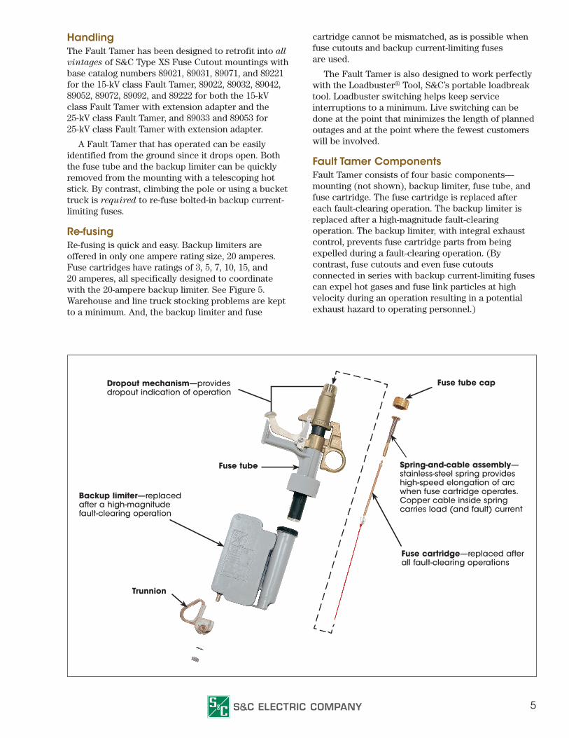
Fault Tamer Components Fault Tamer consists of four basic components—mounting (not shown), backup limiter, fuse tube, and fuse cartridge. The fuse cartridge is replaced after each fault-clearing operation. The backup limiter is replaced after a high-magnitude fault-clearing operation. The backup limiter, with integral exhaust control, prevents fuse cartridge parts from being expelled during a fault-clearing operation. (By contrast, fuse cutouts and even fuse cutouts connected in series with backup current-limiting fuses can expel hot gases and fuse link particles at high velocity during an operation resulting in a potential exhaust hazard to operating personnel.)
Dropout mechanism—providesdropout indication of operation
Backup limiter—replacedafter a high-magnitudefault-clearing operation
Fuse tube
Fuse tube cap
Trunnion
Spring-and-cable assembly—stainless-steel spring provides high-speed elongation of arc when fuse cartridge operates. Copper cable inside spring carries load (and fault) current
Fuse cartridge—replaced after all fault-clearing operations
6
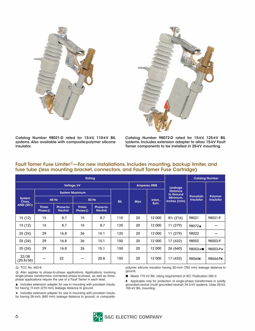
Catalog Number 98021-D rated for 15-kV, 110-kV BIL systems. Also available with composite-polymer silicone insulator.
Catalog Number 98072-D rated for 15-kV, 125-kV BIL systems. Includes extension adapter to allow 15-kV Fault Tamer components to be installed in 25-kV mounting.
Fault Tamer Fuse Limiter①—For new installations. Includes mounting, backup limiter, and fuse tube (less mounting bracket, connectors, and Fault Tamer Fuse Cartridge)
Rating
Leakage Distance
to Ground Minimum,
Inches (mm)
Catalog Number
Voltage, kV Amperes, RMS
Porcelain Insulator
Polymer InsulatorSystem
Class, ANSI (IEC)
System Maximum
BIL Max Interr.,Sym.
60 Hz 50 Hz
Three-Phase②
Phase-to-Neutral
Three-Phase②
Phase-to-Neutral
15 (12) 15 8.7 15 8.7 110 20 12 000 8½ (216) 98021 98021-P
15 (12) 15 8.7 15 8.7 125 20 12 000 11 (279) 98072▲ —
25 (24) 29 16.8 26 15.1 125 20 12 000 11 (279) 98022 —
25 (24) 29 16.8 26 15.1 150 20 12 000 17 (432) 98052 98052-P
25 (24) 29 16.8 26 15.1 150 20 12 000 26 (660) 98053★■ 98053-P★
22/38 (20.8/36) — 22 — 20.8 150 20 12 000 17 (432) 98044◐ 98044-P◐
① TCC No. 450-8.
② Also applies to phase-to-phase applications. Applications involving single-phase transformers connected phase-to-phase, as well as three-phase applications require the use of a Fault Tamer in each lead.
▲ Includes extension adapter for use in mounting with porcelain insula-tor having 11-inch (279 mm) leakage distance to ground.
★ Includes extension adapter for use in mounting with porcelain insula-tor having 26-inch (660 mm) leakage distance to ground, or composite-
polymer silicone insulator having 30-inch (762 mm) leakage distance to ground.
■ Meets 170 kV BIL rating requirement of IEC Publication 282-2.
◐ Applicable only for protection of single-phase transformers in solidly grounded-neutral (multi-grounded-neutral) 34.5-kV systems. Uses 29-kV, 150-kV BIL mounting.
7
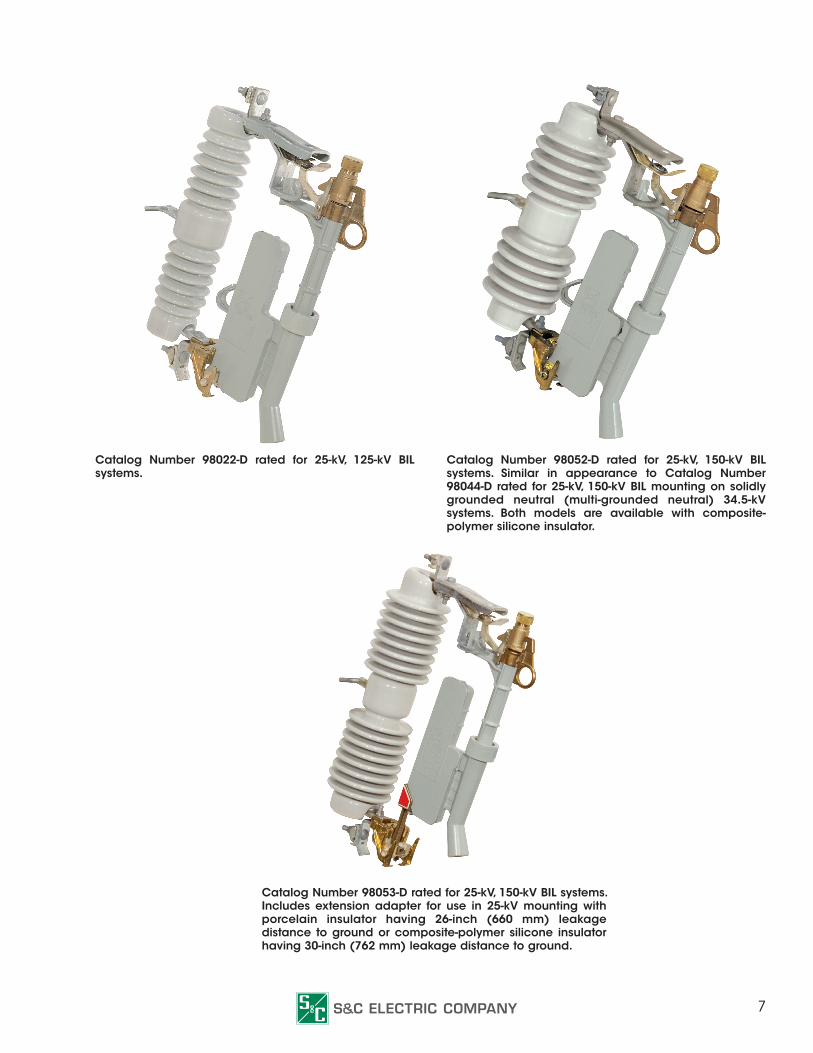
Catalog Number 98022-D rated for 25-kV, 125-kV BIL systems.
Catalog Number 98052-D rated for 25-kV, 150-kV BIL systems. Similar in appearance to Catalog Number 98044-D rated for 25-kV, 150-kV BIL mounting on solidly grounded neutral (multi-grounded neutral) 34.5-kV systems. Both models are available with composite-polymer silicone insulator.
Catalog Number 98053-D rated for 25-kV, 150-kV BIL systems. Includes extension adapter for use in 25-kV mounting with porcelain insulator having 26-inch (660 mm) leakage distance to ground or composite-polymer silicone insulator having 30-inch (762 mm) leakage distance to ground.

Offices Worldwide ■ www.sandc.com
Descriptive Bulletin 451-30 November 17, 2014©