Embed Size (px)
Citation preview
www.fine-tek.com
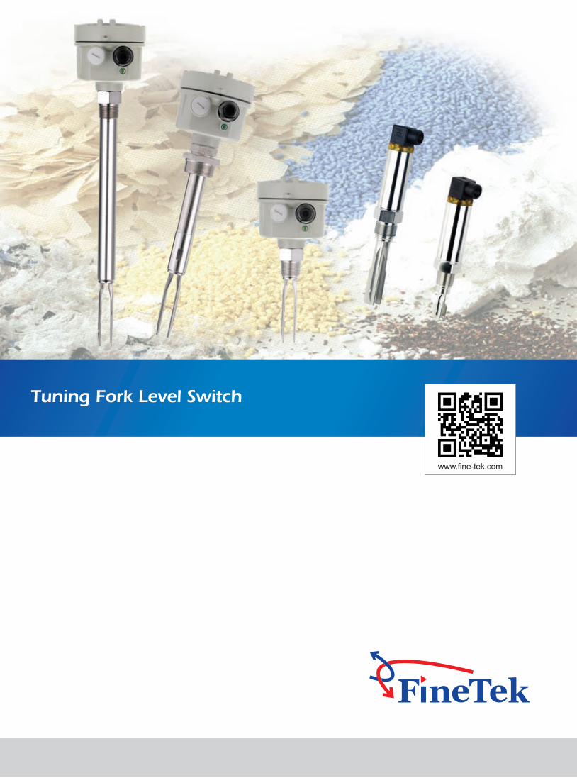
Tuning Fork Level Switch
WORKING PRINCIPLE
The piezoelectric component is used to drive the tuning fork and feedback signal, which produces the resonation on the fork. When the fork comes into contact with a material, the fork will release some frequency signal as feedback. It will be converted into the output of the contact signal when the circuit detects the frequency decrease of the signal. The product relies on the damping effect by covering the testing material on the tuning fork which reduces the vibration frequency of the tuning fork and outputs a switch signal. Therefore, there is no signal amplification circuit inside, which can eliminate the trouble of frequent sensitivity adjustment due to the material change.
FEATURE
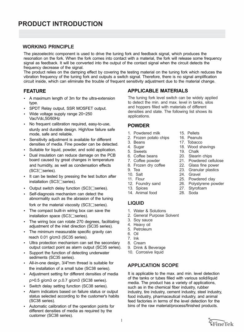
1. Powdered milk2. Frozen potato chips3. Beans4. Sugar5. Sweets6. Coffee beans7. Coffee powder8. Frozen dry coffee9. Tea10. Salt11. Flour 12. Foundry sand13. Spices14. Animal food
The tuning fork level switch can be widely applied to detect the min. and max. level in tanks, silos and hoppers filled with materials of different densities and state. The following list shows itsapplications.
PRODUCT INTRODUCTION
APPLICABLE MATERIALS
POWDER
1. Water & Solutions2. General Purpose Solvent3. Soy sauce4. Heavy oil 5. Petroleum6. Oil7. Ink 8. Cream9. Drink & Beverage10. Corrosive liquid
LIQUID
1
Ÿ A maximum length of 3m for the ultra-extension type.
Ÿ SPDT Relay output, SSR MOSFET output.
Ÿ Wide voltage supply range 20~250 Vac/Vdc,50/60Hz
Ÿ No frequent calibration required, easy-to-use,
sturdy and durable design. High/low failure safe mode, safe and reliable.
Ÿ Sensitivity adjustment is available for different densities of media. Fine powder can be detected.
Ÿ Suitable for liquid, powder, and solid application.
Ÿ Dual insulation can reduce damage on the PCB board caused by great changes in temperature
and humidity, as well as condensation effects
(SC3□ series).
Ÿ It can be tested by pressing the test button after
installation (SC3□ series).
Ÿ Output switch delay function (SC3□ series).
Ÿ Self-diagnosis mechanism can detect the abnormality such as the abrasion of the tuning
fork or the material viscosity (SC3□ series).
Ÿ The compact built-in wiring box can save the
installation space (SC3□ series).
Ÿ The wiring box can rotate 270 degrees, facilitating adjustment of the inlet direction (SC35 series).
Ÿ The minimum measurable specific gravity can
reach 0.01 g/cm3 (SC35 series).
Ÿ Ultra protection mechanism can set the secondary output contact point as alarm output (SC35 series).
Ÿ Support the function of detecting underwater sediments (SC35 series).
Ÿ All-in-one design, 3/4"mm thread is suitable for
the installation of a small tube (SC38 series).
Ÿ Adjustment setting for different densities of media
ρ>0.5 g/cm3 or ρ.0.7 g/cm3 (SC38 series).
Ÿ Switch delay setting function (SC38 series).
Ÿ Alarm indicators based on failure status or output status selected according to the customer's habits (SC38 series).
Ÿ Automatic calibration of the operation points for different densities of media as required by the customer (SC38 series).
15. Pellets16. Peanuts17. Tobacco18. Wood shavings19. Chalk20. Stearin chips21. Powdered cellulose22. Glass fine power23. Granular plastics24. Gravel25. Powdered clay26. Polystyrene powder27. Styrofoam28. Soda
It is applicable to the max. and min. level detection of the tanks or tubes filled with various solid/liquid media. The product has a variety of applications, such as in the chemical fiber industry, rubber industry, tire industry, cement industry, steel industry, food industry, pharmaceutical industry, and animal feed factories in terms of the level detection for the bins of the raw material/process/finished products.
APPLICATION SCOPE
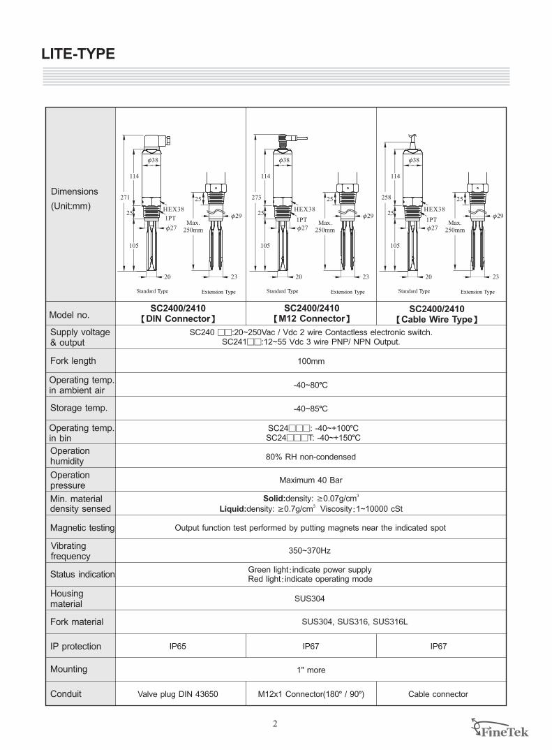
SC2400/2410【DIN Connector】
SC2400/2410【M12 Connector】
SC2400/2410 【Cable Wire Type】
Supply voltage & output
Fork length
Operation humidity
Operation pressure
Magnetic testing
Status indication
Housing material
Fork material
IP protection
Conduit
Dimensions
(Unit:mm)
Operating temp.in ambient air
Operating temp.in bin
Mounting
LITE-TYPE
Storage temp.
Min. material density sensed
SC240 9 :20~250Vac / Vdc SC24199:12~55 Vdc 3 wire PNP/ NPN Output.
9 2 wire Contactless electronic switch.
100mm
-40~80LC
-40~85LC
SC24999: -40~+100LCSC24999T: -40~+150LC
80% RH non-condensed
Maximum 40 Bar
Output function test performed by putting magnets near the indicated spot
Green light:indicate power supplyRed light:indicate operating mode
SUS304
3 Solid:density: ³0.07g/cm3 Liquid:density: ³0.7g/cm Viscosity:1~10000 cSt
2
SUS304, SUS316, SUS316L
IP67
1" more
IP65
Cable connectorValve plug DIN 43650
IP67
Model no.
Extension Type Extension Type Extension TypeStandard Type Standard Type Standard Type
f38
114
25
105
1PT
HEX38
271
f27
20
f38
114
25
105
1PT
HEX38
273
f27
20
f38
114
25
105
1PT
HEX38
258
f27
20
25
f29
23
Max.250mm
25
f29
23
Max.250mm
25
f29
23
Max.250mm
Vibratingfrequency
350~370Hz
M12x1 Connector(180L / 90L)
f38
111
36
40
3/4PTHEX38
217
f21
17
f38
111
36
40
3/4PTHEX38
201
f21
17
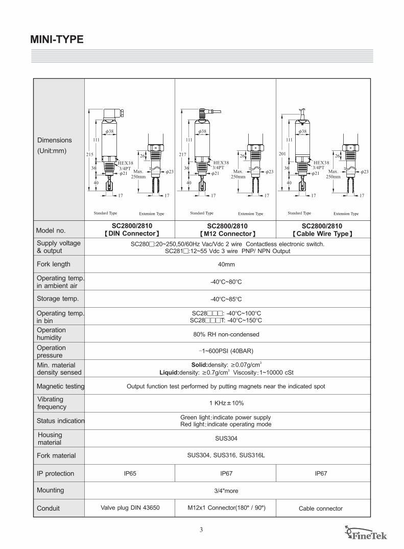
MINI-TYPE
3
SC2800/2810 【DIN Connector】
SC2800/2810 【M12 Connector】
SC2800/2810 【Cable Wire Type】
SC280 : SC2819:12~55 Vdc 3 wire PNP/ NPN Output
9 20~250,50/60Hz Vac/Vdc 2 wire Contactless electronic switch.
40mm
-40 ~80BC BC
-40BC~85BC
80% RH non-condensed
IP67
3/4"more
-1~600PSI (40BAR)
IP65
Cable connectorValve plug DIN 43650
IP67
Supply voltage & output
Fork length
Operation humidity
Operation pressure
Magnetic testing
Status indication
Housing material
Fork material
IP protection
Conduit
Operating temp.in ambient air
Operating temp.in bin
Mounting
Storage temp.
Min. material density sensed
Model no.
3 Solid:density: ³0.07g/cm3 Liquid:density: ³0.7g/cm Viscosity:1~10000 cSt
Output function test performed by putting magnets near the indicated spot
Green light:indicate power supplyRed light:indicate operating mode
Dimensions
(Unit:mm)
Extension Type Extension Type Extension TypeStandard Type Standard Type Standard Type
f38
111
36
40
3/4PTHEX38
215
f21
17
26
f23Max.250mm
17
26
f23Max.250mm
17
26
f23Max.250mm
17
Vibratingfrequency
1 KHzK10%
SUS304
SUS304, SUS316, SUS316L
M12x1 Connector(180L / 90L)
SC28999: -40BC~100BCSC28999T: -40BC~150BC
4
1/2"NPTx2
f27
f113
108
1" PT
105
2520
1"PT
250mm~3M
f27.2
20
105
1/2"NPTx2
f113
108
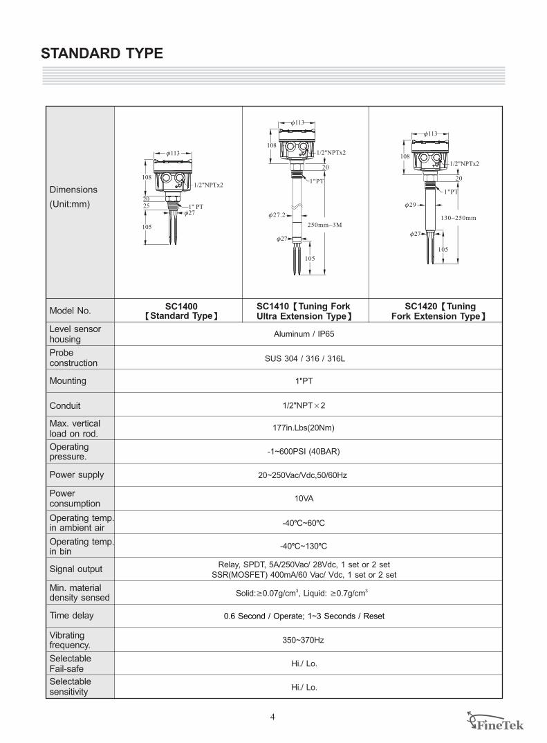
STANDARD TYPE
f27
1"PT
130~250mm
f29
20
105
1/2"NPTx2
f113
108
f27
1"PT
10VA
-40LC~60LC
SUS 304 316 316L / /
350~370Hz
-1~600PSI (40BAR)
3Solid ³ , Liquid: ³0.7g/cm3: 0.07g/cm
1/2"NPTx2
-40LC~130LC
177in.Lbs(20Nm)
0.6 / Operate; 1~3 / ResetSecond Seconds
Hi./ Lo.
Hi./ Lo.
Aluminum / IP65
20~250Vac/Vdc,50/60Hz
Relay, SPDT, 5A/250Vac/ 28Vdc, 1 set or 2 setSSR(MOSFET) 400mA/60 Vac/ Vdc, 1 set or 2 set
SC1400 【Standard Type】
SC1420【Tuning Fork Extension Type】
SC1410【Tuning Fork Ultra Extension Type】
Model No.
Level sensorhousing
Probe construction
Time delay
Selectable Fail-safe
Selectablesensitivity
Power supply
Power consumption
Dimensions
(Unit:mm)
Max. vertical load on rod.
Mounting
Conduit
Signal output
Operating pressure.
Vibrating frequency.
Min. material density sensed
Operating temp.in ambient air
Operating temp.in bin
5
1/2"NPTx2
f113
108
105
1/2"NPTx2
f113
108
105
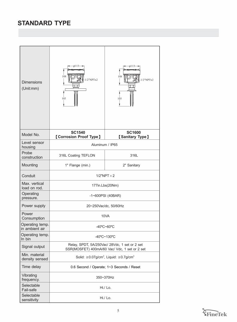
2" Sanitary1" Flange (min.)
STANDARD TYPE
316L Coating TEFLON
Aluminum / IP65
10VA
-40LC~60LC
20~250Vac/dc, 50/60Hz
-1~600PSI (40BAR)
1/2"NPTx2
-40LC~130LC
177in.Lbs(20Nm)
350~370Hz
3Solid ³ , Liquid: ³0.7g/cm3: 0.07g/cm
Hi./ Lo.
Hi./ Lo.
0.6 / Operate; 1~3 / ResetSecond Seconds
Relay, SPDT, 5A/250Vac/ 28Vdc, 1 set or 2 setSSR(MOSFET) 400mA/60 Vac/ Vdc, 1 set or 2 set
316L
SC1540【Corrosion Proof Type】
SC1600【Sanitary Type】
Model No.
Level sensorhousing
Probe construction
Time delay
Selectable Fail-safe
Selectablesensitivity
Power supply
Power Consumption
Dimensions
(Unit:mm)
Max. vertical load on rod.
Mounting
Conduit
Signal output
Operating pressure.
Vibrating frequency.
Min. material density sensed
Operating temp.in ambient air
Operating temp.In bin
EX-PROOF TYPE
6
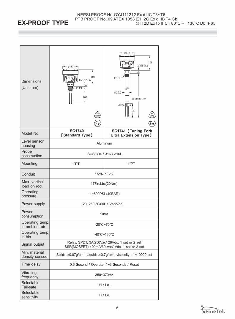
NEPSI PROOF No.GYJ111212 Ex d IIC T3~T6PTB PROOF No. 09 ATEX 1058 II 2G Ex d IIB T4 Gb
II 2D Ex tb IIIC T80BC ~ T130BC Db IP65
1/2"NPTx2
f113
108
1" PT
105
20
Model No.
Level sensorhousing
Probe construction
Time delay
Selectable Fail-safe
Selectablesensitivity
Operating temp.in ambient air
Operating temp.in bin
Power supply
Power consumption
Dimensions
(Unit:mm)
Max. vertical load on rod.
SC1740【Standard Type】
SC1741 Tuning Fork Ultra Extension Type】
【
Mounting
Conduit
Signal output
Operating pressure.
Vibrating frequency.
1"PT
250mm~3M
f27.2
20
105
1/2"NPTx2
f113
108
f27
Min. material density sensed
10VA
-20LC~70LC
350~370Hz
-1~600PSI (40BAR)
1/2"NPTx2
-40LC~130LC
177in.Lbs(20Nm)
Solid ³ , Liquid: ³0.7g/cm viscosity : 1~10000 cst3: 0.07g/cm 3,
Hi./ Lo.
Hi./ Lo.
1"PT
0.6 / Operate; 1~3 / ResetSecond Seconds
1"PT
Relay, SPDT, 3A/250Vac/ 28Vdc, 1 set or 2 setSSR(MOSFET) 400mA/60 Vac/ Vdc, 1 set or 2 set
20~250,50/60Hz Vac/Vdc
Aluminum
SUS 304 316 316L / /
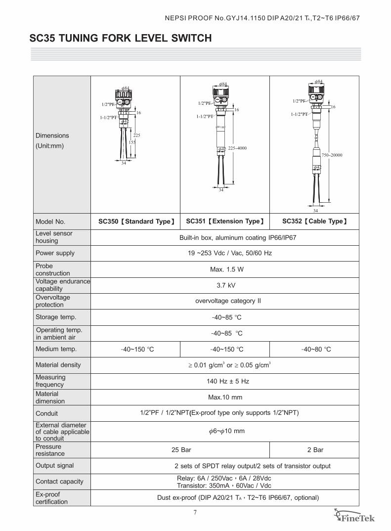
SC35 TUNING FORK LEVEL SWITCH
7
Model No.
Power supply
Voltage endurancecapability
Output signal
Ex-proofcertification
Materialdimension
Conduit
Material density
Measuringfrequency
Dimensions
(Unit:mm)
Operating temp.in ambient air
Overvoltage protection
Storage temp.
External diameterof cable applicableto conduit
Medium temp.
Contact capacity
Pressureresistance
-40~150 BC
3 3³ 0.01 g/cm or ³ 0.05 g/cm
25 Bar
140 Hz ± 5 Hz
Max.10 mm
SC350【 】Standard Type SC351【Extension Type】
1/2”PF / 1/2”NPT(Ex-proof type only supports 1/2”NPT)
Built-in box, aluminum coating IP66/IP67
2 sets of SPDT relay output/2 sets of transistor output
Relay: 6A / 250Vac,6A / 28VdcTransistor: 350mA,60Vac / Vdc
f f6~ 10 mm
19 ~253 Vdc / Vac, 50/60 Hz
Max. 1.5 W
3.7 kV
overvoltage category II
-40~85 BC
-40~85 BC
-40~150 BC -40~80 BC
Dust ex-proof (DIP A20/21 T ,T2~T6 IP66/67, optional)
SC352【Cable Type】
NEPSI PROOF No.GYJ14.1150 DIP A20/21 T ,T2~T6 IP66/67 A
750~20000
225~4000
1-1/2"PT
1/2"PF
f84
16
f42
34
225
155
f84f84
1616
1-1/2"PT
1/2"PF
1-1/2"PT
1/2"PF
34
34
f42
f42
2 Bar
Probe construction
Level sensorhousing
A
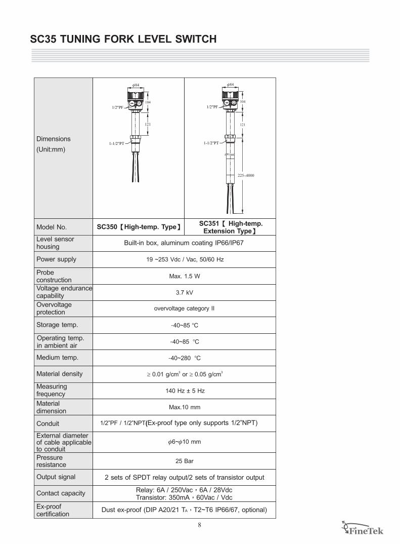
SC35 TUNING FORK LEVEL SWITCH
8
Model No.
Power supply
Voltage endurancecapability
Output signal
Ex-proofcertification
Materialdimension
Conduit
Material density
Measuringfrequency
Dimensions
(Unit:mm)
Operating temp.in ambient air
Overvoltage protection
Storage temp.
External diameterof cable applicableto conduit
Medium temp.
Contact capacity
Pressureresistance
SC350【 】High-temp. Type SC351【 High-temp. Extension Type】
Built-in box, aluminum coating IP66/IP67
2 sets of SPDT relay output/2 sets of transistor output
Relay: 6A / 250Vac,6A / 28VdcTransistor: 350mA,60Vac / Vdc
Dust ex-proof (DIP A20/21 T ,T2~T6 IP66/67, optional)
Probe construction
Level sensorhousing
A
121
225~4000
1-1/2"PT
f84
1/2"PF
1-1/2"PT
f84
1/2"PF104 104
121
-40~280 BC
3 3³ 0.01 g/cm or ³ 0.05 g/cm
25 Bar
140 Hz ± 5 Hz
Max.10 mm
1/2”PF / 1/2”NPT(Ex-proof type only supports 1/2”NPT)
f f6~ 10 mm
19 ~253 Vdc / Vac, 50/60 Hz
Max. 1.5 W
3.7 kV
overvoltage category II
-40~85 BC
-40~85 BC
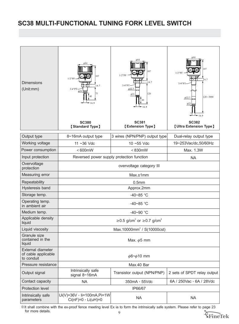
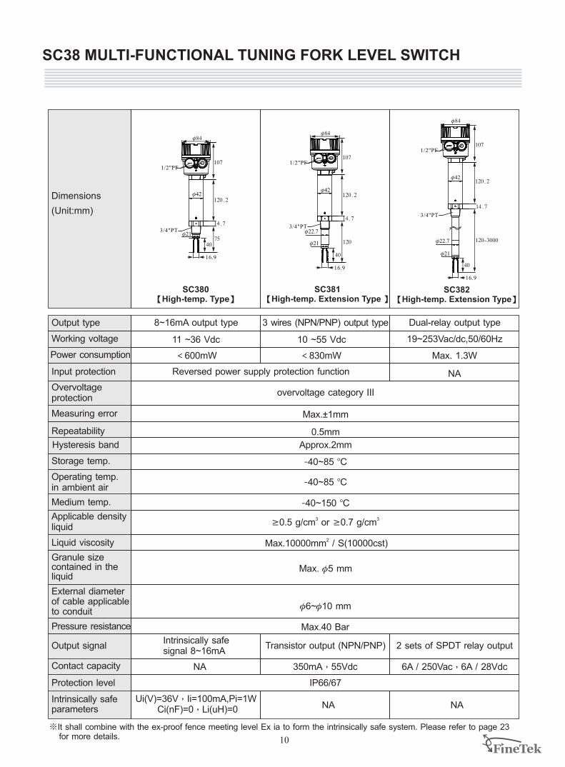
SC38 MULTI-FUNCTIONAL TUNING FORK LEVEL SWITCH
9
Output type
Power consumption
Overvoltageprotection
Pressure resistance
Contact capacity
Liquid viscosity
Operating temp. in ambient air
Medium temp.
Dimensions
(Unit:mm)
Hysteresis band
Measuring error
Repeatability
Storage temp.
Output signal
External diameterof cable applicableto conduit
SC380Standard Type【 】
SC381【Extension Type】
SC382【Ultra Extension Type】
Input protection
Working voltage
1/2"PF
14.7
16.9
f21
f84
107
7540
1/2"PF
f84
14.7
107
120f21
f22.7
40
16.9
14.7
107
120~3000
1/2"PF
f21
f22.7
16.9
f84
Protection level
Intrinsically safeparameters
Granule size contained in theliquid
Applicable densityliquid
Approx.2mm
-40~85 BC
Max. f5 mm
-40~85 BC
-40~90 BC
3 3 ³0.5 g/cm or ³0.7 g/cm
11 ~36 Vdc
Max.40 Bar
2Max.10000mm / S(10000cst)
<600mW
Max.±1mm
0.5mm
overvoltage category III
19~253Vac/dc,50/60Hz
Max. 1.3W
f6~f10 mm
10 ~55 Vdc
<830mW
NA
8~16mA output type Dual-relay output type3 wires (NPN/PNP) output type
Intrinsically safe signal 8~16mA
Transistor output (NPN/PNP) 2 sets of SPDT relay output
350mA,55Vdc 6A / 250Vac,6A / 28Vdc
IP66/67
Ui(V)=36V,Ii=100mA,Pi=1W Ci(nF)=0,Li(uH)=0
Reversed power supply protection function
※It shall combine with the ex-proof fence meeting level Ex ia to form the intrinsically safe system. Please refer to page 23 for more details.
NA NA
NA
3/4"PT
3/4"PT3/4"PT
SC38 MULTI-FUNCTIONAL TUNING FORK LEVEL SWITCH
10
Output type
Power consumption
Overvoltageprotection
Pressure resistance
Contact capacity
Liquid viscosity
Operating temp. in ambient air
Medium temp.
Dimensions
(Unit:mm)
Hysteresis band
Measuring error
Repeatability
Storage temp.
Output signal
External diameterof cable applicableto conduit
SC380High-temp. Type【 】
SC381【High-temp. Extension Type 】
SC382【High-temp. Extension Type】
Input protection
Working voltage
Protection level
Intrinsically safeparameters
Granule size contained in theliquid
Applicable densityliquid
Approx.2mm
-40~85 BC
Max. f5 mm
-40~85 BC
-40~150 BC
3 3 ³0.5 g/cm or ³0.7 g/cm
11 ~36 Vdc
Max.40 Bar
2Max.10000mm / S(10000cst)
<600mW
Max.±1mm
0.5mm
overvoltage category III
19~253Vac/dc,50/60Hz
Max. 1.3W
f6~f10 mm
10 ~55 Vdc
<830mW
NA
8~16mA output type Dual-relay output type3 wires (NPN/PNP) output type
Intrinsically safe signal 8~16mA
Transistor output (NPN/PNP) 2 sets of SPDT relay output
350mA,55Vdc 6A / 250Vac,6A / 28Vdc
IP66/67
Ui(V)=36V,Ii=100mA,Pi=1W Ci(nF)=0,Li(uH)=0
Reversed power supply protection function
※It shall combine with the ex-proof fence meeting level Ex ia to form the intrinsically safe system. Please refer to page 23 for more details.
1/2"PF
1/2"PF
1/2"PF
f84
107
120.2
75
14.7
107
120.2
120
14.7
f84
40
16.9
f21
f42
40
16.9
f21
f22.7
f42
f84
107
120~3000
14.7
40
16.9
120.2
f21
f22.7
f42
NA NA
NA
3/4"PT3/4"PT
3/4"PT
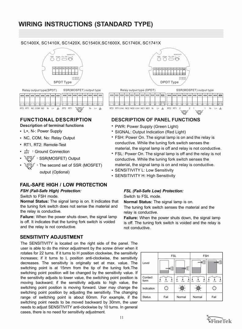
WIRING INSTRUCTIONS (STANDARD TYPE)
SC1400X, SC1410X, SC1420X, SC1540X,SC1600X, SC1740X, SC1741X
L+, N-: Power Supply
NC, COM, No: Relay Output
RT1, RT2: Remote-Test
:Ground Connection
:SSR(MOSFET) Output
:The second set of SSR (MOSFET)
output (Optional)
FUNCTIONAL DESCRIPTION Description of terminal functions
SENSITIVITY
HLFSL FSHSIGNALPWR
20~250VAC20~250VDC
SENSITIVITY
HLFSL FSHSIGNALPWR
20~250VAC20~250VDC
Relay output type(SPDT)
SPDT Type DPDT Type
SSR(MOSFET) output type
RT2 RT1 NC NO N- L+COM RT2 RT1 N- L+
Relay output type (DPDT) SSR(MOSFET) output type
RT2 RT1 NC2 NO2 N- L+COM2 NC1 NO1COM1 RT2 RT1 22 1 N- L+1
DESCRIPTION OF PANEL FUNCTIONS
PWR: Power Supply (Green Light)
SIGNAL: Output Indication (Red Light)
FSH: Power On. The signal lamp is on and the relay is
conductive. While the tuning fork switch senses the
material, the signal lamp is off and relay is not conductive.
FSL: Power On. The signal lamp is off and the relay is not
conductive. While the tuning fork switch senses the
material, the signal lamp is on and relay is conductive.
SENSITIVITY L: Low Sensitivity
SENSITIVITY H: High Sensitivity
FSH (Fail-Safe High) Protection:
Switch to FSH mode.Normal Status: The signal lamp is on. It indicates that the tuning fork switch does not sense the material and the relay is conductive.
Failure: When the power shuts down, the signal lamp is off. It indicates that the tuning fork switch is voided and the relay is not conductive.
FSL (Fail-Safe Low) Protection:
Switch to FSL mode.
Normal Status: The signal lamp is on.
The tuning fork switch senses the material and the relay is conductive.
Failure: When the power shuts down, the signal lamp is off. The tuning fork switch is voided and the relay is not conductive.
The SENSITIVITY is located on the right side of the panel. The user is able to do the minor adjustment by the screw driver when it rotates for 22 turns. If it turns to H position clockwise, the sensitivity increases; if it turns to L position anti-clockwise, the sensitivity decreases. The sensitivity is originally set at max. value. The switching point is at 15mm from the tip of the tuning fork.The switching point position will be changed by the sensitivity value. If the sensitivity adjusts to lower value, the switching point position is moving backward; if the sensitivity adjusts to high value, the switching point position is moving forward. User may change the switching point position by adjusting the sensitivity. The changing range of switching point is about 60mm. For example, if the switching point needs to be moved backward by 30mm, the user needs to adjust SENSITIVITY anti-clockwise by 10 turns. In general cases, there is no need for sensitivity adjustment.
FAIL-SAFE HIGH / LOW PROTECTION
SENSITIVITY ADJUSTMENT
11
Fail FailNormal Normal
Level
Contact form
Indication
Status
FSL FSH
COMNO NC COM NCNO COM NCNO COMNO NC
PNP NPNMax. Min. Max. Min.
1 23
L+N-PE
R
1 23
R
L+N-PE
1 23
R
PE L+ N-
PNP NPNMax. Min. Max. Min.
L+N-PE L+N-PE L+ N-PE L+ N-PE
N-L+PE
1 23
DIN Wiring Diagram
M12x1、Cable Wiring Diagram
Figure 2 PNP / NPN Output Wiring Diagram
Brown Black
Blue
YellowGreen
Brown Black
Blue
YellowGreen
Brown Black
Blue
YellowGreen
Brown Black
Blue
YellowGreen
BlackBlue
BrownYellow Green
BlackBlue
BrownYellow Green
BlackBlue
BrownYellow Green
BlackBlue
BrownYellow Green
BlackBlue
BrownYellow Green
BlackBlue
BrownYellow Green
BlackBlue
BrownYellow Green
BlackBlue
BrownYellow Green
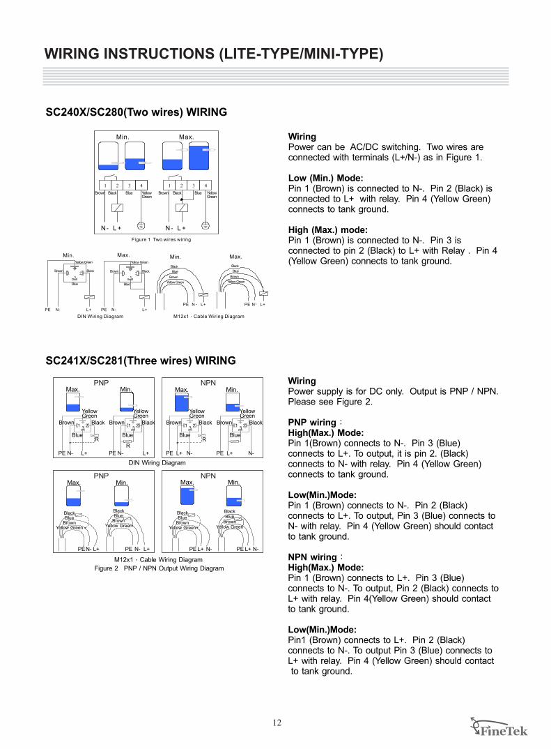
SC240X/SC280(Two wires) WIRING
Figure 1 Two wires wiring
Min. Max.
1 42 3 1 42 3
L +N- L +N-
Min. Max.
PE L+N - PE L+N-
Min. Max.
DIN Wiring Diagram M12x1、Cable Wiring Diagram
1 23
L+N-PEL+N-PE
1 23
Brown Black Blue Yellow Green
Brown Black Blue Yellow Green
Brown
Black
Blue
Yellow Green
Brown
Black
Blue
Yellow Green
Yellow Green Yellow Green
Blue
Brown Black Brown Black
Blue
WiringPower can be AC/DC switching. Two wires are connected with terminals (L+/N-) as in Figure 1.
Low (Min.) Mode: Pin 1 (Brown) is connected to N-. Pin 2 (Black) is connected to L+ with relay. Pin 4 (Yellow Green) connects to tank ground.
High (Max.) mode: Pin 1 (Brown) is connected to N-. Pin 3 is connected to pin 2 (Black) to L+ with Relay . Pin 4 (Yellow Green) connects to tank ground.
SC241X/SC281(Three wires) WIRING
WiringPower supply is for DC only. Output is PNP / NPN. Please see Figure 2.
PNP wiring:High(Max.) Mode: Pin 1(Brown) connects to N-. Pin 3 (Blue) connects to L+. To output, it is pin 2. (Black) connects to N- with relay. Pin 4 (Yellow Green) connects to tank ground.
Low(Min.)Mode: Pin 1 (Brown) connects to N-. Pin 2 (Black) connects to L+. To output, Pin 3 (Blue) connects to N- with relay. Pin 4 (Yellow Green) should contact to tank ground.
NPN wiring:High(Max.) Mode: Pin 1 (Brown) connects to L+. Pin 3 (Blue) connects to N-. To output, Pin 2 (Black) connects to L+ with relay. Pin 4(Yellow Green) should contact to tank ground.
Low(Min.)Mode: Pin1 (Brown) connects to L+. Pin 2 (Black) connects to N-. To output Pin 3 (Blue) connects to L+ with relay. Pin 4 (Yellow Green) should contact to tank ground.
WIRING INSTRUCTIONS (LITE-TYPE/MINI-TYPE)
12
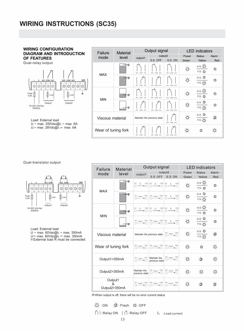
WIRING CONFIGURATION DIAGRAM AND INTRODUCTIONOF FEATURESDual-relay output
Materiallevel
Output signal
Green Yellow Red
Failuremode output1
output2 Status Alarm
S.S. ONS.S. OFF
LED indicators
O.S.
F.S.
O.S.
F.S.
O.S.
F.S.
O.S.
F.S.
O.S.
F.S.
NO2 COM2 NC2
NO1 COM1 NC1 NO2 COM2 NC2
NO1 COM1 NC1 NO2 COM2 NC2
NO1 COM1 NC1 NO2 COM2 NC2
NO1 COM1 NC1 NO2 COM2 NC2
NO1 COM1 NC1 NO2 COM2 NC2
NO2 COM2 NC2
NO2 COM2 NC2
NO2 COM2 NC2
NO2 COM2 NC2
NO2 COM2 NC2
MAX
MIN
Viscous material
Wear of tuning fork
Power
L N GNDNO1 COM1 NC1 NO2 COM1 NC2
Output1 Output2
L N GNDNO1 COM1 NO2 COM2
Output1 Output2
output1output2 Status Alarm
S.S. ONS.S. OFF
O.S.
F.S.
O.S.
F.S.
O.S.
F.S.
O.S.
F.S.
O.S.
F.S.
MAX
MIN
Power
Output1>350mA
Output2>350mA
Output1&
Output2>350mA
NO2 COM2<100mA
NO1 COM1<100mA
NO2 COM2<100mA
NO2 COM2<100mA
NO1 COM1<100mA
NO2 COM2<100mA
NO1 COM1Ll NO2 COM2
Ll NO2 COM2Ll
NO2 COM2Ll
NO2 COM2LlNO2 COM2
LlNO1 COM1Ll
NO2 COM2<100mA
NO2 COM2<100mA
NO2 COM2<100mA
NO2 COM2<100mA
NO1 COM1<100mA
NO2 COM2<100mA
NO2 COM2Ll
NO2 COM2<100mA
NO1 COM1<100mA
NO1 COM1<100mA
:ON :Flash :OFF
:Relay ON :Relay OFF :Load currentLl
※When output is off, there will be no error current status
L
L
Load: U ~ max. 60Vac@I ~ max. 350mAU max. 60Vdc@I max. 350mA
External load
※Extermal load R must be connected
19~253 Vdc/Vac50/60Hz
Fuse0.5A
LoadLoad
L
L
Load: External loadU ~ max. 250Vac@I ~ max. 6AU max. 28Vdc@I max. 6A
19~253 Vdc/Vac50/60Hz
Fuse0.5A LoadLoad
WIRING INSTRUCTIONS (SC35)
Dual-transistor output
Materiallevel
Output signal
Green Yellow Red
Failuremode
LED indicators
Viscous material
Wear of tuning fork
13
Maintain theprevious state
Maintain theprevious state
Maintain the previous state
Maintain the previous state
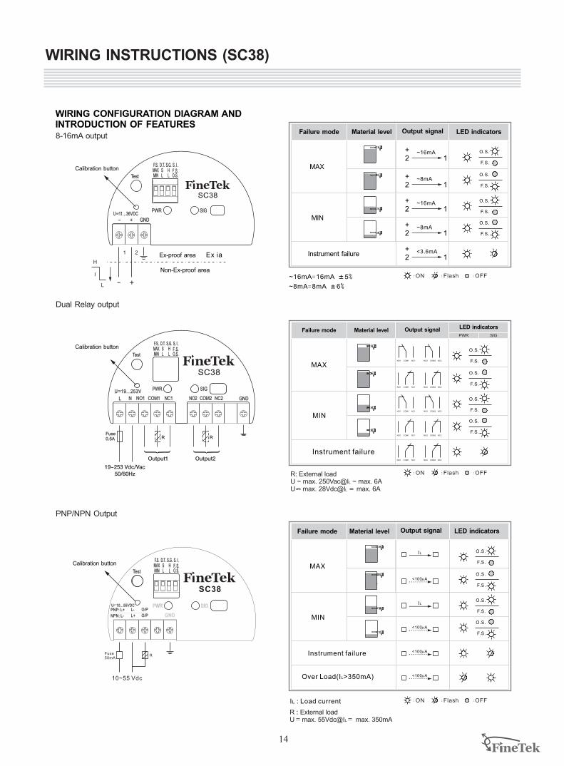
WIRING CONFIGURATION DIAGRAM AND INTRODUCTION OF FEATURES
- + GND
PWR SIG
F.S.MAXMIN
D.T.SL
S.G.HL
S. I .
O.S.Test
SC38
U 11...36VDC- - -
F .S.
+-
Ex-proof area
Non-Ex-proof area
L
H
I
Ex ia1 2
MAX
MIN
O.S.
F.S.
O.S.
F.S.
O.S.
F.S.
O.S.
F.S.
~16mA=16mA K5%
~8mA=8mA K6%
Instrument failure+2 1
<3.6mA
+2 1
~8mA
+2 1
~16mA
+2 1
~8mA
+2 1
~16mA
F.S.MAXMIN
D.T.SL
S.G.HL
S. I .
O.S.Test
SC38
F .S.
L N NO1 NO2 COM2 GNDNC1
U 19...253V~-
NC2
PWR SIG
COM1
Fuse0.5A
Output1 Output2
RR
19~253 Vdc/Vac50/60Hz
L
L
R: U ~ max. 250Vac@I ~ max. 6AU max. 28Vdc@I max. 6A
External load
Calibration button
MAX
MIN
O.S.
F.S.
O.S.
F.S.
O.S.
F.S.
O.S.
F.S.
Instrument failure
PWR SIG
NO1 COM1 NC1 NO2 COM2 NC2
NO1 COM1 NC1 NO2 COM2 NC2
NO1 COM1 NC1 NO2 COM2 NC2
NO2 COM2 NC2NO1 COM1 NC1
NO1 COM1 NC1 NO2 COM2 NC2
L
RU max. 55Vdc@I max. 350mA
: External load
R
10~55 Vdc
Fuse50mA
NPN: L- L+ O/P GNDPNP: L+ L- O/P
PWR SIG
F.S.MAXMIN
D.T.SL
S.G.HL
S. I .
O.S.Test
SC38
F .S.
U 10...55VDC-
I : Load currentL
MAX
MIN
O.S.
F.S.
O.S.
F.S.
O.S.
F.S.
O.S.
F.S.
Instrument failure
Over Load(IL>350mA)
<100mA
<100 Am
<100 Am
IL
IL
<100 Am
:ON :Flash :OFF
WIRING INSTRUCTIONS (SC38)
8-16mA output
Dual Relay output
Calibration button
Calibration button
PNP/NPN Output
LED indicatorsOutput signalFailure mode Material level
LED indicatorsOutput signalFailure mode Material level
LED indicatorsOutput signalFailure mode Material level
:ON :Flash :OFF
:ON :Flash :OFF
14
Output Status for Relay Output Status for PNP / NPN Transistor
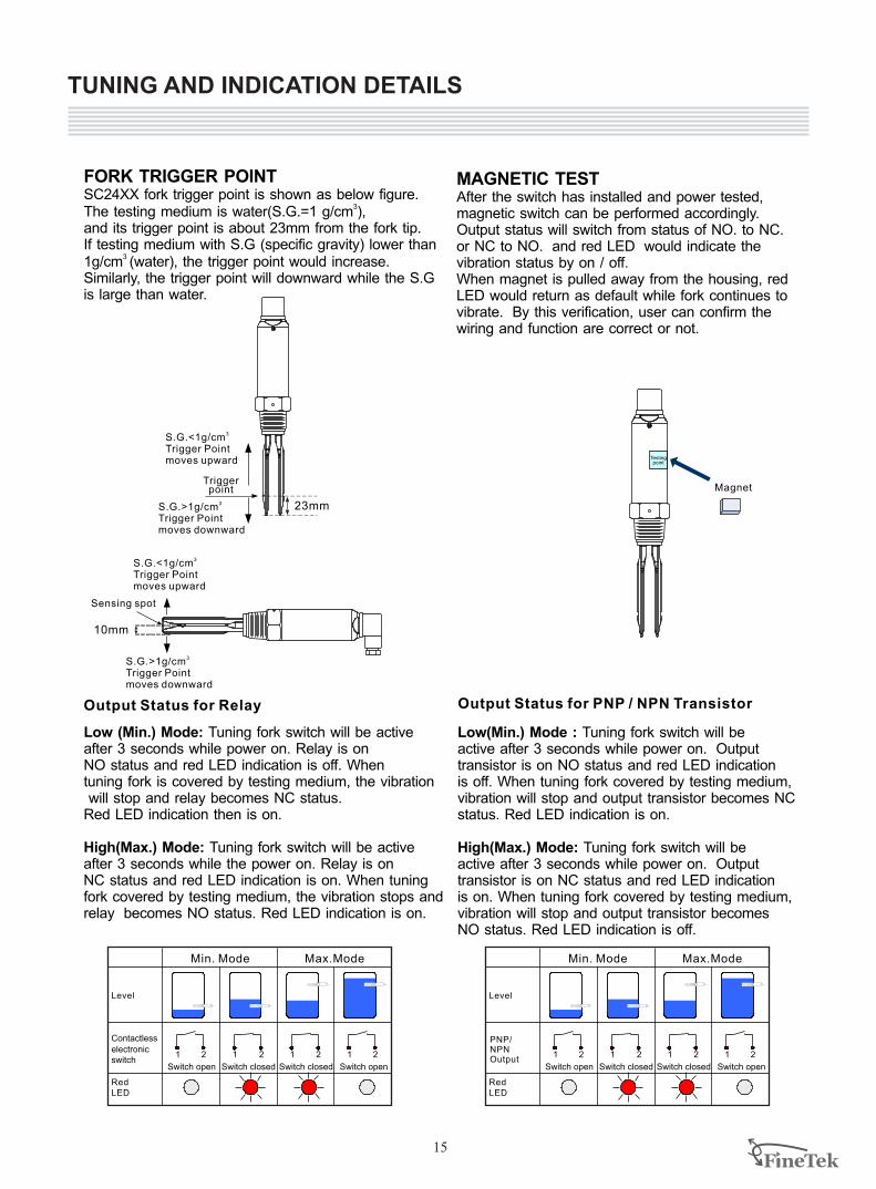
23mm
10 mm
Testingpoint
FORK TRIGGER POINTSC24XX fork trigger point is shown as below figure.
3The testing medium is water(S.G.=1 g/cm ), and its trigger point is about 23mm from the fork tip. If testing medium with S.G (specific gravity) lower than
3 1g/cm (water), the trigger point would increase. Similarly, the trigger point will downward while the S.Gis large than water.
Triggerpoint
3S.G.<1g/cmTrigger Pointmoves upward
3S.G.>1g/cmTrigger Pointmoves downward
3S.G.<1g/cmTrigger Pointmoves upward
3S.G.>1g/cmTrigger Pointmoves downward
Sensing spot
MAGNETIC TESTAfter the switch has installed and power tested, magnetic switch can be performed accordingly. Output status will switch from status of NO. to NC.or NC to NO. and red LED would indicate the vibration status by on / off.When magnet is pulled away from the housing, red LED would return as default while fork continues to vibrate. By this verification, user can confirm the wiring and function are correct or not.
Magnet
Min. Mode Max.Mode
Level
Contactless electronic switch
1 2 1 2 1 2 1 2
Switch open
Red LED
Switch closed Switch openSwitch closed
Low (Min.) Mode: Tuning fork switch will be activeafter 3 seconds while power on. Relay is onNO status and red LED indication is off. When tuning fork is covered by testing medium, the vibration will stop and relay becomes NC status. Red LED indication then is on.
High(Max.) Mode: Tuning fork switch will be active after 3 seconds while the power on. Relay is onNC status and red LED indication is on. When tuning fork covered by testing medium, the vibration stops and relay becomes NO status. Red LED indication is on.
Low(Min.) Mode : Tuning fork switch will be active after 3 seconds while power on. Output transistor is on NO status and red LED indication is off. When tuning fork covered by testing medium, vibration will stop and output transistor becomes NCstatus. Red LED indication is on.
High(Max.) Mode: Tuning fork switch will be active after 3 seconds while power on. Output transistor is on NC status and red LED indication is on. When tuning fork covered by testing medium, vibration will stop and output transistor becomes NO status. Red LED indication is off.
TUNING AND INDICATION DETAILS
15
PNP/NPNOutput
Min. Mode Max.Mode
Level
1 2 1 2 1 2 1 2
Switch open
Red LED
Switch closed Switch openSwitch closed
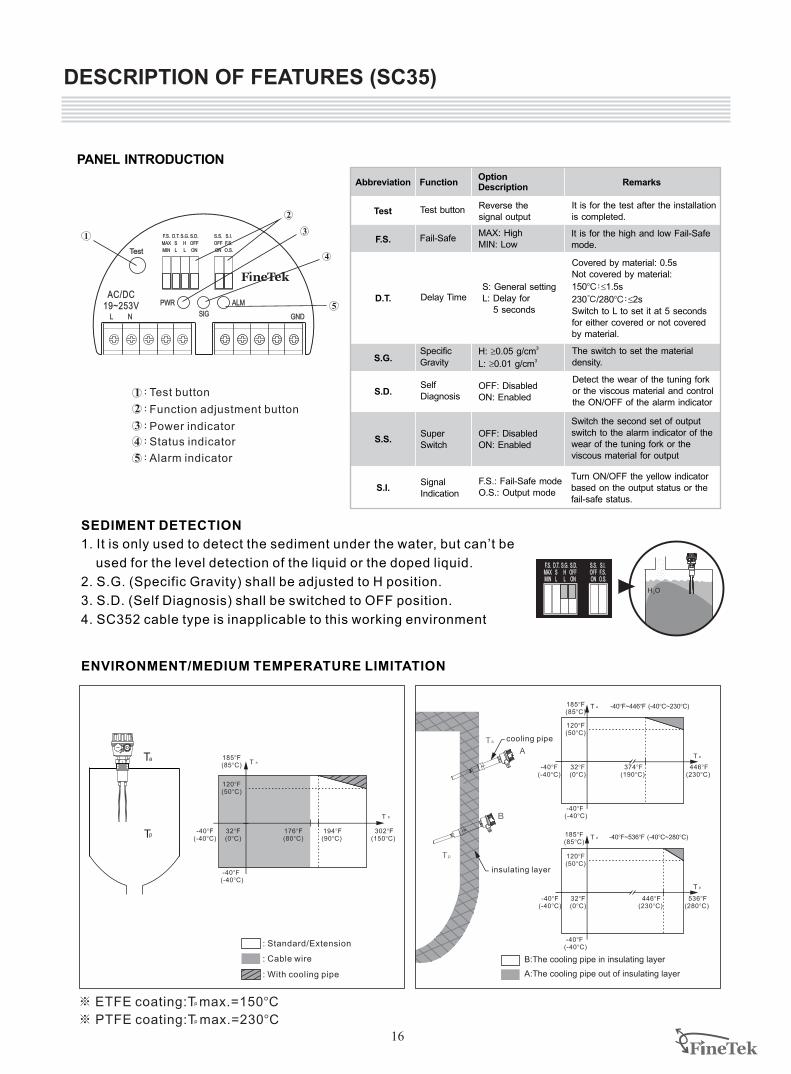
DESCRIPTION OF FEATURES (SC35)
Abbreviation
Test
Function
Test button
OptionDescription
Reverse thesignal output
F.S. Fail-SafeMAX: HighMIN: Low
D.T. Delay TimeS: General settingL: Delay for 5 seconds
S.G.SpecificGravity
H: ³ 30.05 g/cm
L: 3³0.01 g/cm
S.D.Self Diagnosis
OFF: DisabledON: Enabled
S.S.
S.I.
SuperSwitch
OFF: DisabledON: Enabled
SignalIndication
F.S.: Fail-Safe modeO.S.: Output mode
It is for the test after the installationis completed.
Remarks
It is for the high and low Fail-Safemode.
Covered by material: 0.5sNot covered by material:
150 : 1.5s
230℃ 280 : 2s
Switch to L to set it at 5 secondsfor either covered or not covered by material.
BC
BC
£
/ £
The switch to set the material density.
Detect the wear of the tuning forkor the viscous material and controlthe ON/OFF of the alarm indicator
Switch the second set of outputswitch to the alarm indicator of thewear of the tuning fork or the viscous material for output
Turn ON/OFF the yellow indicatorbased on the output status or thefail-safe status.
L N GNDSIG
PWR ALM
F.S.
MAX
MIN
D.T.
S
L
S.G.
H
L
S.D.
OFF
ON
S.I.
F.S.
O.S.
S.S.
OFF
ON
AC/DC19~253V
Test
1
2
3
4
5
T a
T p
T a
T p
-40 F (-40 C)
BB
Ta
Tp
185 F(85 C)
BB
: Standard/Extension
: Cable wire
176 F(80 C)
BB
32 F (0 C)BB
194 F (90 C)
BB
302 F (150 C)
BB
-40 F (-40 C)
BB
120 F (50 C)
BB
-40 F (-40 C)
BB
185 F(85 C)
BB
32 F (0 C)BB
-40 F (-40 C)
BB
120 F (50 C)
BB
374 F (190 C)
BB
446 F (230 C)
BB
T p
T a
A:The cooling pipe out of insulating layer
B:The cooling pipe in insulating layer
T a
T p
-40 F (-40 C)
BB
185 F(85 C)
BB
32 F (0 C)BB
120 F (50 C)
BB
446 F (230 C)
BB
536 F (280 C)
BB
-40 F (-40 C)
BB
-40 F~446 F (-40 C~230 C)B B B B
-40 F~536 F (-40 C~280 C)B B B B
A
B
insulating layer
cooling pipe
1. It is only used to detect the sediment under the water, but can’t be
used for the level detection of the liquid or the doped liquid.
2. S.G. (Specific Gravity) shall be adjusted to H position.
3. S.D. (Self Diagnosis) shall be switched to OFF position.
4. SC352 cable type is inapplicable to this working environment
SEDIMENT DETECTION
H O2
F.S.MAXMIN
D.T.SL
S.G.HL
S.D.OFFON
S.I.F.S.O.S.
S.S.OFFON
: With cooling pipe
※ ETFE coating:T max.=150BC
※ PTFE B coating:T max.=230 Cp
p
PANEL INTRODUCTION
ENVIRONMENT/MEDIUM TEMPERATURE LIMITATION
1
2
3
4
5
:Test button
:Function adjustment button
:Power indicator
:Status indicator
:Alarm indicator
16
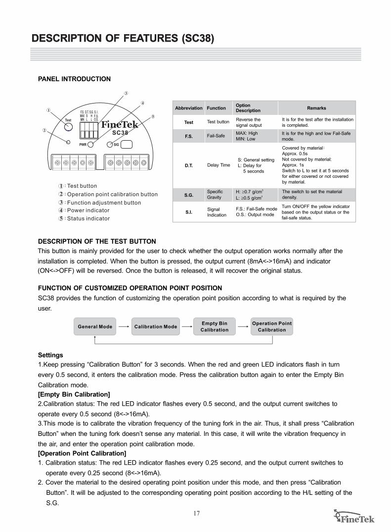
DESCRIPTION OF FEATURES (SC38)
PANEL INTRODUCTION
SC38 provides the function of customizing the operation point position according to what is required by the
user.
Settings
1.Keep pressing “Calibration Button” for 3 seconds. When the red and green LED indicators flash in turn
every 0.5 second, it enters the calibration mode. Press the calibration button again to enter the Empty Bin
Calibration mode.
[Empty Bin Calibration]
2.Calibration status: The red LED indicator flashes every 0.5 second, and the output current switches to
operate every 0.5 second (8<->16mA).
3.This mode is to calibrate the vibration frequency of the tuning fork in the air. Thus, it shall press “Calibration
Button” when the tuning fork doesn’t sense any material. In this case, it will write the vibration frequency in
the air, and enter the operation point calibration mode.
[Operation Point Calibration]
1. Calibration status: The red LED indicator flashes every 0.25 second, and the output current switches to
operate every 0.25 second (8<->16mA).
2. Cover the material to the desired operating point position under this mode, and then press “Calibration
Button”. It will be adjusted to the corresponding operating point position according to the H/L setting of the
S.G.
General Mode
PWR SIG
F.S.MAXMIN
D.T.SL
S.G.HL
S. I .
O.S.Test
SC38
F .S.
1
2
3
4
5
1
2
3
4
5
:Test button
:Operation point calibration button
:Function adjustment button
:Power indicator
:Status indicator
Abbreviation
Test
Function
Test button
OptionDescription
Reverse thesignal output
F.S. Fail-SafeMAX: HighMIN: Low
D.T. Delay TimeS: General settingL: Delay for 5 seconds
S.G.SpecificGravity
H: ³ 30.7 g/cm
L: 3³0.5 g/cm
S.I.SignalIndication
F.S.: Fail-Safe modeO.S.: Output mode
It is for the test after the installationis completed.
Remarks
It is for the high and low Fail-Safemode.
Covered by material:Approx. 0.5sNot covered by material:Approx. 1sSwitch to L to set it at 5 secondsfor either covered or not covered by material.
The switch to set the material density.
Turn ON/OFF the yellow indicatorbased on the output status or thefail-safe status.
DESCRIPTION OF THE TEST BUTTON
FUNCTION OF CUSTOMIZED OPERATION POINT POSITION
This button is mainly provided for the user to check whether the output operation works normally after the
installation is completed. When the button is pressed, the output current (8mA<->16mA) and indicator
(ON<->OFF) will be reversed. Once the button is released, it will recover the original status.
Calibration ModeEmpty Bin
Calibration
Operation Point
Calibration
DESCRIPTION OF FEATURES (SC38)
17
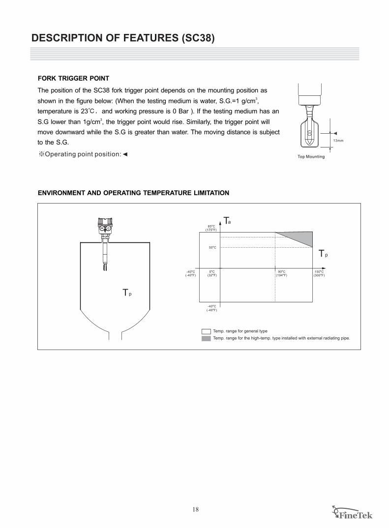
The position of the SC38 fork trigger point depends on the mounting position as 3shown in the figure below: (When the testing medium is water, S.G.=1 g/cm ,
temperature is 23℃, and working pressure is 0 Bar ). If the testing medium has an 3S.G lower than 1g/cm , the trigger point would rise. Similarly, the trigger point will
move downward while the S.G is greater than water. The moving distance is subject
to the S.G. 13mm
Top Mounting※Operating point position:
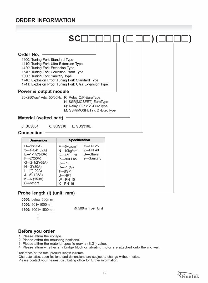
150LC(300LF)
90LC(194LF)
-40LC( LF)-40
-40LC(-40LF)
Ta
Tp
0LC(32LF)
85LC(175LF)
50LC
Tp
DESCRIPTION OF FEATURES (SC38)
FORK TRIGGER POINT
ENVIRONMENT AND OPERATING TEMPERATURE LIMITATION
Temp. range for the high-temp. type installed with external radiating pipe.
Temp. range for general type
18
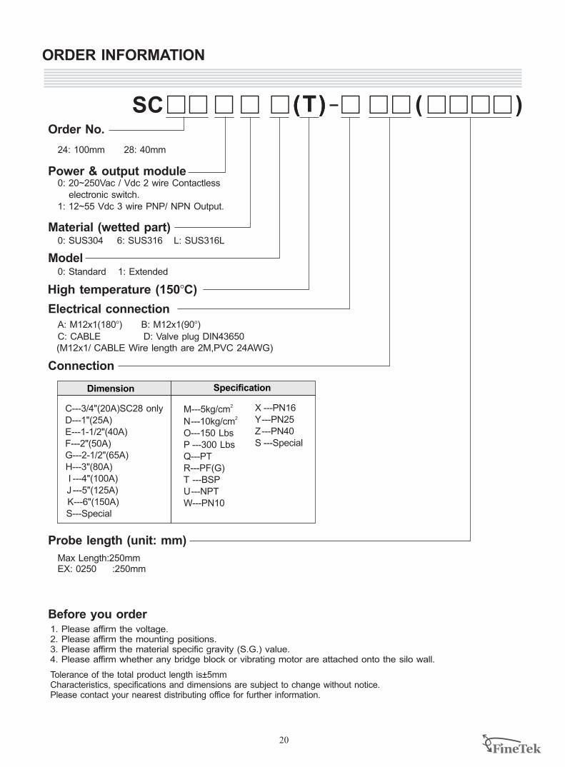
Order No.
Connection
Probe length (l) (unit: mm)
Before you order1. Please affirm the voltage.2. Please affirm the mounting positions.3. Please affirm the material specific gravity (S.G.) value.4. Please affirm whether any bridge block or vibrating motor are attached onto the silo wall.
Tolerance of the total product length is 5mm±Characteristics, specifications and dimensions are subject to change without notice.Please contact your nearest distributing office for further information.
Power & output module
ORDER INFORMATION
2M---5kg/cm2N---10kg/cm
O---150 LbsP---300 LbsQ---PTR---PF(G)T---BSPU---NPTW---PN 10X---PN 16
Y---PN 25Z---PN 40S---others9---Sanitary
Material (wetted part)
0: SUS304 6: SUS316 L: SUS316L
20~250Vac/ Vdc, 50/60Hz
1400: Tuning Fork Standard Type1410: Tuning Fork Ultra Extension Type1420: Tuning Fork Extension Type1540: Tuning Fork Corrosion Proof Type1600: Tuning Fork Sanitary Type1740: Explosion Proof Tuning Fork Standard Type1741: Explosion Proof Tuning Fork Ultra Extension Type
D---1"(25A)3---1-1/4"(32A)E---1-1/2"(40A)F---2"(50A)G---2-1/2"(65A)H---3"(80A)I---4"(100A)J---5"(125A)K---6"(150A)S---others
Dimension Specification
0500: below 500mm
1000: 501~1000mm
1500: 1001~1500mm 500mm per Unit
19
R: Relay O/P-EuroTypeN: SSR(MOSFET) EuroTypeQ: Relay O/P x 2 -EuroTypeM: SSR(MOSFET) x 2 -EuroType
A: M12x1(180B) B: M12x1(90B)
C: CABLE D: Valve plug DIN43650
High temperature (150BC)
ORDER INFORMATION
20
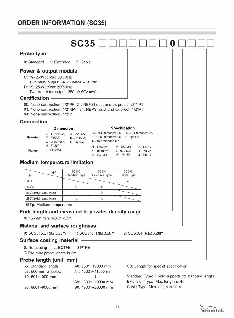
SC
24: 100mm 28: 40mm
0: 20~250Vac / Vdc 2 wire Contactless electronic switch.1: 12~55 Vdc 3 wire PNP/ NPN Output.
Order No.
Power & output module
Material (wetted part)0: SUS304 6: SUS316 L: SUS316L
Dimension Specification
2M---5kg/cm2N ---10kg/cm
O---150 LbsP ---300 LbsQ---PTR---PF(G)
T ---BSPU ---NPTW---PN10
C---3/4"(20A)SC28 only D---1"(25A)E---1-1/2"(40A)F---2"(50A)G---2-1/2"(65A) H---3"(80A) I ---4"(100A) J ---5"(125A) K---6"(150A) S---Special
X ---PN16Y ---PN25Z ---PN40S ---Special
Model
Electrical connection
0: Standard
Connection
1. Please affirm the voltage.2. Please affirm the mounting positions.3. Please affirm the material specific gravity (S.G.) value.4. Please affirm whether any bridge block or vibrating motor are attached onto the silo wall.
Tolerance of the total product length is±5mmCharacteristics, specifications and dimensions are subject to change without notice.Please contact your nearest distributing office for further information.
1: Extended
(M12x1/ CABLE Wire length are 2M,PVC 24AWG)
Before you order
Probe length (unit: mm)
Max Length:250mmEX: 0250 :250mm
ORDER INFORMATION (SC35)
21
0: Standard 1: Extended 2: Cable
C: 19~253Vdc/Vac 50/60Hz Two relay output: 6A 250Vac/6A 28VdcD: 19~253Vdc/Vac 50/60Hz Two transistor output: 350mA 60Vac/Vdc
Probe type
Power & output module
Certification00: None certification, 1/2"PF 31: NEPSI dust and ex-proof, 1/2"NPT01: None certification, 1/2"NPT 34: NEPSI dust and ex-proof, 1/2"PT04: None certification, 1/2"PT
Connection
Material and surface roughness
0: SUS316L, Ra 3.2um 1: SUS316, Ra 3.2um 2: SUS304, Ra 3.2um£ £ £
SC35 0
E---1-1/2"(40A)
F---2"(50A)
G---2-1/2"(65A)
H---3"(80A)
I---4"(100A)
Threaded
Flange
Q---PT(R)threaded tub
R---PF(G)threaded tub
T---BSP threaded tub
TypeTp
80℃
150℃
SC350 Standard Type
0 2
4
J---5"(125A)
K---6"(150A)
S---Special
U---NPT threaded tub
S---Special
2M---5 kg/cm 2N---10 kg/cm
O---150 Lbs
X---PN 16
Y---PN 25
Z---PN 40
P---300 Lbs
W---PN 10
L---600 Lbs
230℃ High-temp type ( )
280℃(High-temp type) 5 6
1 3
SC351 Extension Type
SC352 Cable Type
Dimension
Medium temperature limitation
Fork length and measurable powder density range0: 155mm min.
3³0.01 g/cm
※Tp: Medium temperature
Surface coating material
0: No coating 2: ECTFE 3.PTFE
※The max probe length is 3m
Standard length
05: 500 mm
10: 501~1000 mm
xx:
95: 9001~9500 mm
or below
...
A0: 9501~10000 mm
A1: 10001~11000 mm
A9: 18001~19000 mm
B0: 19001~20000 mm
...
SS: Length for special specification
Standard Type: It only supports xx standard length
Extension Type: Max length is 4m
Cable Type: Max length is 20m
Probe length (unit: mm)
Specification
ORDER INFORMATION (SC38)
22
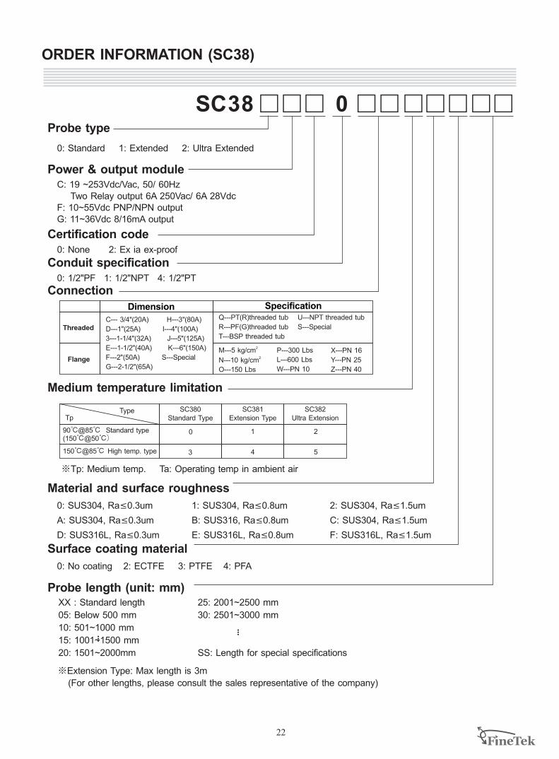
0: Standard 1: Extended 2: Ultra Extended
C: 19 ~253Vdc/Vac, 50/ 60Hz Two Relay output 6A 250Vac/ 6A 28VdcF: 10~55Vdc PNP/NPN outputG: 11~36Vdc 8/16mA output
Probe type
Power & output module
Certification code0: None 2: Ex ia ex-proof
Connection
Material and surface roughness
0: SUS304, Ra£ 0.3um
A: SUS304, Ra£ 0.3um
D: SUS316L, Ra£ 0.3um
C--- 3/4"(20A) H---3"(80A)
D---1"(25A) I---4"(100A)
3---1-1/4"(32A) J---5"(125A)
E---1-1/2"(40A) K---6"(150A)
F---2"(50A) S---Special
G---2-1/2"(65A)
Threaded
Flange
Q---PT(R)threaded tub
R---PF(G)threaded tub
T---BSP threaded tub
TypeTp
SC380 Standard Type
U---NPT threaded tub
S---Special
2M---5 kg/cm 2N---10 kg/cm
O---150 Lbs
X---PN 16
Y---PN 25
Z---PN 40
P---300 Lbs
W---PN 10
L---600 Lbs
90℃ 85℃ Standard type(150℃ 50℃)
@@
3 4
0 1
SC381 Extension Type
SC382 Ultra Extension
Dimension
Medium temperature limitation
※Tp: Medium temp. Ta: Operating temp in ambient air
Surface coating material
0: No coating 2: ECTFE 3: PTFE 4: PFA
XX : Standard length
05: Below 500 mm
10: 501~1000 mm
15: 1001~1500 mm
20: 1501~2000mm
...
...
Probe length (unit: mm)
SC38 0
Conduit specification 0: 1/2"PF 1: 1/2"NPT 4: 1/2"PT
5
2
1: SUS , Ra 0.8um 304 £
B: SUS316, Ra£ 0.8um
E: SUS316L, Ra£ 0.8um
2: SUS304, Ra 1.5um£
C: SUS304, Ra£ 1.5um
F: SUS316L, Ra£ 1.5um
25: 2001~2500 mm
30: 2501~3000 mm
SS: Length for special specifications
※Extension Type: Max length is 3m
(For other lengths, please consult the sales representative of the company)
Specification
150℃ 85℃ High temp. type@
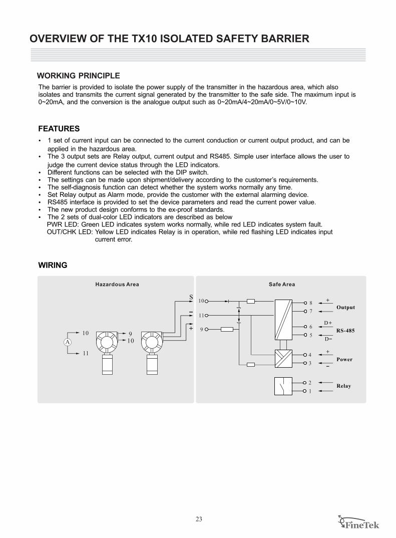
WORKING PRINCIPLE
The barrier is provided to isolate the power supply of the transmitter in the hazardous area, which also isolates and transmits the current signal generated by the transmitter to the safe side. The maximum input is 0~20mA, and the conversion is the analogue output such as 0~20mA/4~20mA/0~5V/0~10V.
FEATURES
OVERVIEW OF THE TX10 ISOLATED SAFETY BARRIER
WIRING
23
Ÿ 1 set of current input can be connected to the current conduction or current output product, and can be
applied in the hazardous area.Ÿ The 3 output sets are Relay output, current output and RS485. Simple user interface allows the user to
judge the current device status through the LED indicators.Ÿ Different functions can be selected with the DIP switch. Ÿ The settings can be made upon shipment/delivery according to the customer’s requirements. Ÿ The self-diagnosis function can detect whether the system works normally any time.Ÿ Set Relay output as Alarm mode, provide the customer with the external alarming device. Ÿ RS485 interface is provided to set the device parameters and read the current power value. Ÿ The new product design conforms to the ex-proof standards.Ÿ The 2 sets of dual-color LED indicators are described as below
PWR LED: Green LED indicates system works normally, while red LED indicates system fault.OUT/CHK LED: Yellow LED indicates Relay is in operation, while red flashing LED indicates input
current error.
Hazardous Area
11
10
9
3
4
1
2
5
6
7
8
+
D
D+
Relay
Power
RS-485
Output
S
11
10+
109
Safe Area
-
-
+
-Α
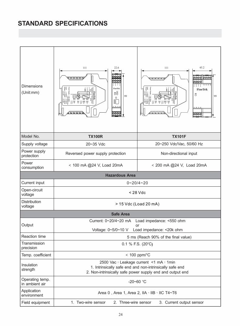
Operating temp.in ambient air
Transmissionprecision
Reaction time
Output
Supply voltage
Distributionvoltage
Open-circuitvoltage
Powerconsumption
Insulationstrength
2500 Vac;Leakage current <1 mA;1min1. Intrinsically safe end and non-intrinsically safe end
2. Non-intrinsically safe power supply end and output end
Current: 0~20/4~20 mA Load impedance: <550 ohmor
Voltage: 0~5/0~10 V Load impedance: <20k ohm
-20~60 BC
Power supplyprotection
Temp. coefficient
Current input
0.1 % F.S. (20BC)
20~35 Vdc
Area 0 , Area 1, Area 2, IIA、IIB、IIC T4~T6
< 100 ppm/BC
Reversed power supply protection
< 100 mA @24 V, Load 20mA
Application environment
Field equipment
TX100R
20~250 Vdc/Vac, 50/60 Hz
Non-directional input
TX101FModel No.
< 200 mA @24 V, Load 20mA
22.6
SW1SW2SW3SW4
/CHK
OUT
PWR
1 2 3 4 5 6 7 8
9 10 11 12
10
119
1 2 5 6 7 8
-
+
D D+
Rela
y
Po
wer
RS
-485
Ou
tpu
t
-
Ha
za
rdo
us
A
rea
sN
on
-ha
za
rdo
us
A
rea
s
Po
we
r Su
pp
ly:
20
~3
5V
dc
Inp
ut:
0~
20
mA
Ou
tpu
t: 0
~2
0m
A
4~
20
mA
5
5
5
55 0
~5
V5
0~
10
V
5 2
0~
25
0Va
c/V
dc
5 E
nab
le
5 D
isab
le
5 E
nab
le
5 D
isab
le
5 4
~2
0m
A
111
99
45.210
119
1 2 5 6 7 8
-
+
D D+
Rela
y
Po
wer
RS
-485
Ou
tpu
t
-
Ha
za
rdo
us
A
rea
sN
on
-ha
za
rdo
us
A
rea
s
Po
we
r Su
pp
ly:
20
~3
5V
dc
Inp
ut:
0~
20
mA
Ou
tpu
t: 0
~2
0m
A
4~
20
mA
5
5
5
55 0
~5
V5
0~
10
V
5 2
0~
25
0Va
c/V
dc
5 E
nab
le
5 D
isab
le
5 E
nab
le
5 D
isab
le
5 4
~2
0m
A
111
99PWR
1 2 3 4 5 6 7 8
13 14 15 16
9 10 11 12
STANDARD SPECIFICATIONS
24
Hazardous Area
Safe Area
1. Two-wire sensor 2. Three-wire sensor 3. Current output sensor
0~20/4~20
< 28 Vdc
> 15 Vdc (Load 20 mA)
5 ms (Reach 90% of the final value)
Dimensions
(Unit:mm)
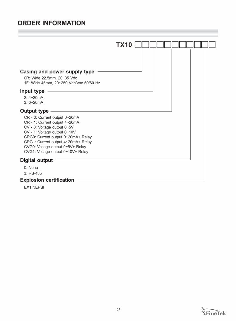
ORDER INFORMATION
25
0R: Wide 22.5mm, 20~35 Vdc1F: Wide 45mm, 20~250 Vdc/Vac 50/60 Hz
Casing and power supply type
Input type2: 4~20mA3: 0~20mA
Digital output
0: None
3: RS-485
Output typeCR - 0: Current output 0~20mA CR - 1: Current output 4~20mA CV - 0: Voltage output 0~5VCV - 1: Voltage output 0~10VCRG0: Current output 0~20mA+ RelayCRG1: Current output 4~20mA+ RelayCVG0: Voltage output 0~5V+ RelayCVG1: Voltage output 0~10V+ Relay
Explosion certification
EX1:NEPSI
TX10

Global Network
Taiwan -
No.16, Tzuchiang St., Tucheng Industrial Park New Taipei City 236, TaiwanTEL: 886-2-2269-6789FAX: 886-2-2268-6682EMAIL: [email protected]
FINETEK CO., LTD. - I-Lan FactoryTEL: 886-3-990-9669FAX: 886-3-9909659
FINETEK CO., LTD. - Taichung BranceTEL: 886-4-2337-0825FAX: 886-4-2337-0836
FINETEK CO., LTD. - Kaohsiung BranchTEL: 886-7-333-6968 FAX: 886-7-536-8758
China FINE AUTOMATION CO., LTD. - Shanghai FactoryNo.451 DuHui Rd, MinHang District, Shanghai, China 201109TEL: 86-21-6490-7260FAX: 86-21-6490-7276EMAIL: [email protected]
SingaporeFINETEK PTE LTD. - Singapore OfficeNo. 60 Kaki Bukit Place, #07-06 Eunos Techpark 2 Lobby B, Singapore 415979TEL: 65-6452-6340FAX: 65-6734-1878EMAIL: [email protected]
FINETEK CO., LTD. Taipei Head QuarterCalifornia, U.S.
355 S. Lemon Ave, Suite D, Walnut, CA 91789TEL: 1 909 598 2488 FAX: 1 909 598 3188EMAIL: [email protected]
Illinois, U.S.APLUS FINETEK SENSOR INC.TEL: 1 815 632-3132 FAX: 1 815 716 8464EMAIL: [email protected]
APLUS FINETEK SENSOR INC. - US OfficeGermanyFineTeK GmbH - Germany OfficeFrankfurter Str. 62, OG D-65428 Ruesselsheim, GermanyTEL: +49-(0)6142-17608-0FAX: +49-(0)6142-17608-20EMAIL: [email protected]
Asia North America Europe
Taiwan
China
U.S.
Germany
U.S.
Singapore
08-SC02-B3-EP, 09/01/2015
Distributor: