Embed Size (px)
Citation preview
SCADA AND TELECOM SYSTEMFOR AGCL GAS PIPELINENETWORK - PAHSE-II Project No. P.005712Document No. P.005712 D 11050 002
ASSAM GAS COMPANY LTDAssam | INDIA
PUBLIC
30 January 2019
TECHNICAL DOCUMENTATIONTechnical, Vol II of III
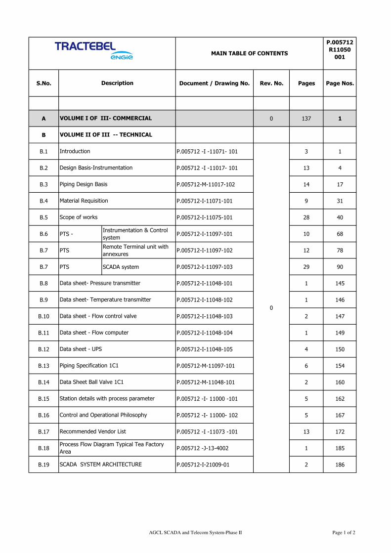
S.No. Document / Drawing No. Rev. No. Pages Page Nos.
A 0 137 1
B
B.1 P.005712 -I -11071- 101 3 1
B.2 P.005712 -I -11017- 101 13 4
B.3 P.005712-M-11017-102 14 17
B.4 P.005712-I-11071-101 9 31
B.5 P.005712-I-11075-101 28 40
B.6 PTS -Instrumentation & Control
systemP.005712-I-11097-101 10 68
B.7 PTSRemote Terminal unit with
annexuresP.005712-I-11097-102 12 78
B.7 PTS SCADA system P.005712-I-11097-103 29 90
B.8 P.005712-I-11048-101 1 145
B.9 P.005712-I-11048-102 1 146
B.10 P.005712-I-11048-103 2 147
B.11 P.005712-I-11048-104 1 149
B.12 P.005712-I-11048-105 4 150
B.13 P.005712-M-11097-101 6 154
B.14 P.005712-M-11048-101 2 160
B.15 P.005712 -I- 11000 -101 5 162
B.16 P.005712 -I- 11000- 102 5 167
B.17 P.005712 -I -11073 -101 13 172
B.18 P.005712 -J-13-4002 1 185
B.19 P.005712-I-21009-01 2 186
Data sheet - Flow computer
MAIN TABLE OF CONTENTS
Data sheet- Pressure transmitter
Data sheet - Flow control valve
Data sheet- Temperature transmitter
0
P.005712
R11050
001
Description
VOLUME I OF III- COMMERCIAL
Scope of works
Material Requisition
Piping Design Basis
Introduction
VOLUME II OF III -- TECHNICAL
Design Basis-Instrumentation
Process Flow Diagram Typical Tea Factory
Area
Data Sheet Ball Valve 1C1
Recommended Vendor List
Data sheet - UPS
Control and Operational Philosophy
Piping Specification 1C1
Station details with process parameter
SCADA SYSTEM ARCHITECTURE
AGCL SCADA and Telecom System-Phase II Page 1 of 2
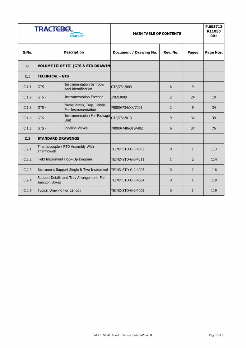
S.No. Document / Drawing No. Rev. No. Pages Page Nos.
MAIN TABLE OF CONTENTS
P.005712
R11050
001
Description
C
C.1
C.1.1 GTS - GTS/734/003 6 9 1
C.1.2 GTS - J/02/3009 2 24 10
C.1.3 GTS - 70000/734/XX/7001 2 5 34
C.1.4 GTS - Instrumentation For Package
Unit GTS/734/013 9 37 39
C.1.5 GTS - 70000/740/GTS/402 6 37 76
C.2
C.2.1 TEIND-STD-G-J-4002 0 1 113
C.2.2 TEIND-STD-G-J-4011 1 2 114
C.2.3 TEIND-STD-G-J-4003 0 2 116
C.2.4 TEIND-STD-G-J-4004 0 1 118
C.2.5 TEIND-STD-G-J-4005 0 1 119
VOLUME III OF III (GTS & STD DRAWING)
TECHNICAL - GTS
Instrumentation Symbols
And Identification
Instrument Support Single & Two Instrument
Support Details and Tray Arrangement For
Junction Boxes
Typical Drawing For Canopy
Instrumentation Erection
Name Plates, Tags, Labels
For Instrumentation
Pipeline Valves
STANDARD DRAWINGS
Thermocouple / RTD Assembly With
Thermowell
Field Instrument Hook-Up Diagram
AGCL SCADA and Telecom System-Phase II Page 2 of 2
INTRODUCTION
P.005712
I-11071
101
ASSAM GAS COMPANY LTD
SCADA AND TELECOM SYSTEM FOR AGCL GAS PIPELINE
NETWORK - PAHSE-II
TRACTEBEL ENGINEERING PVT. LTD.
INTRODUCTION
RERT
DOC. NO. P.005712-I-11071- 101
0 23.01.2019 Release for procurement MA SHD SK
Rev. Date Subject of revision Prepared By Checked By Approved By
Page 1 of 187
INTRODUCTION
P.005712
I-11071
101
Rev.0 AGCL SCADA and Telecom System Project-Phase-II Page I of I
TABLE OF CONTENTS
1.0 INTRODUCTION ...................................................................................................................... 1
Page 2 of 187
INTRODUCTION
P.005712
I-11071
101
Rev.0 AGCL SCADA and Telecom System Project-Phase-II Page 1 of 1
1.0 INTRODUCTION
1.1 Assam Gas Company Ltd., Duliajan has been in the business of transporting high pressure and low pressure
natural gas, through its transmission and distribution network covering five districts of upper Assam, India to
several key segments.
1.2 The gas is collected presently from sources of OIL and ONGCL. However, gas from other producers may
also be injected into AGCL network as and when available. The compressed gas is transported by dedicated
and common carriers lines to industries such as Brahmaputra Valley Fertilizer Corporation Ltd (BVFCL),
Assam Petrochemical Limited (APL), Namrup Thermal Power Station (NTPS) and uncompressed natural gas
to Lakwa thermal power station (LTPS) and Power Plant of NEEPCO. The company also supplies low
pressure natural gas to over 400 tea factories/industrial consumers spread over five districts of Upper Assam.
1.3 Assam gas company Ltd. Duliajan is planning to build a supervisory control & data acquisition system
(SCADA) and GSM/GPRS (4G/LTE) based Telecommunication system for acquiring, monitoring and
controlling the process data from all Gas pipeline network spread over five districts of upper Assam.
Hereafter the project is called as “SCADA AND TELECOM SYSTEM FOR AGCL GAS PIPELINE
NETWORK-PHASE-II
1.4 SCADA and Telecom system facilities for PHASE-I for 74 number of tea factories and 8 major consumers
locations has completed by Assam gas company Ltd. Presently running SCADA system is
“SCADAvantage” from M/s ABB and communicating with RTU on DNP 3.0 (TCP/IP) protocol. Bidder
shall make provision in PAHSE -II SCADA system for integration with existing SCADA system or directly
from RTU.
1.5 Tractebel Engineering Private Limited (TE-IN) has been appointed by AGCL for Consultancy service for
setting up this project of AGCL.
1.6 Tractebel Engineering Private Limited (TE-IN), in coordination with AGCL team has completed site survey
for all the stations. Site survey report shall be made available to the successful bidder.
1.7 Assam gas company Ltd. (AGCL) Duliajan / Tractebel Engineering –India (TE-IN), Delhi is inviting tender
on Open Domestic Competitive bidding basis from competitive bidders under single stage two envelops
system for engineering procurement & construction (EPC) services for setting up this project.
1.8 The present document covers the technical specifications for this tender. The tender document shall be read
in conjunction with Vol. I of III - Commercial, Vol. II of III- Instrumentation & Control system and Vol III
of III -General Technical specification (GTS) and Standard Drawing
Σ Σ Σ
Page 3 of 187
DESIGN BASIS
INSTRUMENTATION
P.005712
I-11017
101
ASSAM GAS COMPANY LTD
SCADA AND TELECOM SYSTEM FOR AGCL GAS PIPELINE
NETWORK - PAHSE-II
TRACTEBEL ENGINEERING PVT. LTD.
DESIGN BASIS
INSTRUMENTATION RERT
DOC. NO. P.005712 -I-11017-101
0 23.01.2019 Release for Procurement MA SHD SK
Rev. Date Subject of revision Prepared By Checked By Approved By
Page 4 of 187
DESIGN BASIS
INSTRUMENTATION
P.005712
I-11017
101
Rev.0 AGCL SCADA and Telecom System Project-Phase-II Page 1 of 1
TABLE OF CONTENTS
1.0 INTRODUCTION ................................................................................................................... 1
2.0 APPLICABLE CODES & STANDARD ....................................................................................... 1
3.0 SITE CONDITIONS ............................................................................................................... 3
4.0 POWER SUPPLY .................................................................................................................... 3
5.0 TEA FACTORY ....................................................................................................................... 3
6.0 INSTRUMENT SPECIFICATION ............................................................................................ 5
7.0 FLOW CONTROL VALVE ........................................................................................................ 6
8.0 INSTRUMENTATION EARTHING SYSTEM ............................................................................. 6
9.0 INSTRUMENT CABLES .......................................................................................................... 7
10.0 REMOTE TERMINAL UNIT (RTU) .......................................................................................... 7
11.0 TELECOMMUNICATION SYSTEM FOR SCADA NETWORKING ............................................... 8
12.0 MASTER CONTROL STATION- SCADA................................................................................... 9
Page 5 of 187
DESIGN BASIS
INSTRUMENTATION
P.005712
I-11017
101
Rev.0 AGCL SCADA and Telecom System Project-Phase-II Page 1 of 11
1.0 INTRODUCTION
1.1 This document is engineered based on feasibility study carried out during site survey and presents the
philosophy of remote control & monitoring facility at tea factory from SCADA system through wireless
communication.
1.2 AGCL envisages establishing a New SCADA & telecommunications network, using 3G/4G/LTE GSM
system, to interconnect the Pipeline system through Supervisory Control and Data Acquisition (SCADA)
with Remote Terminal Units (RTU’s) for recording, monitoring and control at 325 tea factories/industrial
consumers from Master Control Station at AGCL Corporate Office, Duliajan. The monitoring and control
facility shall ensure that the consumer shall not be able to withdraw more gas than the allocated quantity.
This is to ensure availability of gas for last mile connectivity. The objective of setting up a SCADA System
is always to supply of gas to consumers as per agreed quantity at agreed delivery pressure and ensure that in
common carrier situations, over withdrawal by a single/few consumer do not occur under set conditions.
However, when there is excess gas available in the pipeline network, such overdraw up to 150% of agreed
quantity may be permitted.
1.3 Project Objective
Prime Project objective of project as follows
a. Control the gas flow through FCV to tea factories as per allocated quantity
b. In case of availability of excess gas in grid, permit the customer to withdraw more gas within 150% of
the agreed quantity by changing the set point from SCADA.
c. Monitoring Gas flow, FCV status from remote stationed SCADA system
1.4 Design, manufacturing, supply, testing, installation, including piping modification, integration with existing
flow meter (EVC) and commissioning of Flow Control valve, RTU with integrated or separate GSM modem,
pressure transmitter at inlet of each factory, preparation of earthing pit, SCADA system and UPS for power
backup at each tea/Industrial factory.
1.5 Design, manufacturing, supply, testing, installation, and commissioning of Dual SIM enabled
3G/4G/LTE/latest & upcoming technology compatible GSM modem with supply / activation of SIM cards
and coordination with service provider for connectivity at different locations.
1.6 Modification/shifting works including supply, installation of erection material for changing of existing
Tapping Point from downstream of FCV to upstream of FCV with moisture separator/Filter at 74 locations of
Naharkatia, Moran& Sonari area
1.7 Vendor’s responsibility is to establish communication between RTU and SCADA and bring all the tea
factories data up to the SCADA system.
2.0 APPLICABLE CODES & STANDARD
2.1 The following Indian/ international or relevant codes and standards shall be used for designing the system. In
all cases, latest revisions with amendments, if any, to be followed. Apart from the specific codes mentioned
herein, all other relevant and related codes concerning the specific job under consideration and/or referred to
in these codes and technical specifications shall be followed wherever applicable. All codes shall be of the
latest revision as on the date of issuing the tender/ bid document.
2.2 In the event of any conflict between this specification, related standards and codes, any other attachment to
this tender, the Contractor shall refer the matter to CLIENT/CLIENT’S
REPRESENTATIVE/CONSULTANT for clarification and only after obtaining confirmation, Contractor
shall proceed for manufacturing / supply of the item. The decision of the CLIENT/CLIENT’S
REPRESENTATIVE shall be binding on the Contractor.
Page 6 of 187
DESIGN BASIS
INSTRUMENTATION
P.005712
I-11017
101
Rev.0 AGCL SCADA and Telecom System Project-Phase-II Page 2 of 11
2.3 CONTRACTOR shall ask COMPANY's interpretation / clarification for any confusion (if any) prior to the
start of execution of work. Rework because of misunderstanding / misinterpretation by contractor shall be
done at no additional cost to the COMPANY by the contractor.
Sr.
No
Codes Description
1 OISD-STD-226 Natural Gas Transmission Pipelines and City Gas Distribution
Networks.
2 ANSI/ISA S 51.1 Process Instrumentation Terminology.
3 ISA 5.4 Instruments Loop diagrams.
4 IEC 60529 / IS 2147 /
NEMA
Specification for Weather Proof Enclosure.
5 IEC 60079/IS 2148 Specification for Flame Proof Enclosure
6 IEC 61000 Electromagnetic Compatibility for Industrial Process
Measurement and Control equipments.
7 IEC 60801 EMI and RF interference
8 IS-1554 Part 1 PVC insulated (heavy duty) electric cables- working voltage up
to and including 1100V.
9 BS-5308 Part 1, Type 2 Specification for PVC insulated cables.
10 IS 8130 Conductors of insulated cables
11 IS 5831 Specification for PVC insulation and sheath of insulated cables.
12 IS-3975 Mild steel wires, formed wires and tapes for armouring of cables.
13 ASTM D 2843 Test method for Max smoke density for cable
14 ASTM D 2863 Test method for measuring of Temp and O2 Index.
15 IEC 60754 Acid generation test
16 IEC-332-3 Part 3 Tests on bunched wires and cables.
17 BS 6121, EN 50262 Cable gland – flame proof Exd or Exe increase safety.
18 DIN- 50049 Document on Material Testing.
19 ASME PTC 19.3 Temperature Measurement- calculation of natural frequency.
20 IEC 751 / DIN 43760 RTD
21 IEC 584/DIN 43710 / ANSI
MC 96.1
Thermocouple
22 ISO 5167 Measurement of fluid flow by means of orifice plates, Nozzles
and Venturi tube inserted in filled piping circular profile.
23 ASME B 16.36 Orifice flange with flange pressure tap.
24 ASME B16.5 Pipe line flanges and flanged fittings
25 API-RP-520 Sizing and selection of safety relief valves.
26 IS 3624 / BS EN 837 Pressure gauge
27 AGA 3 Orifice flow measurement
28 AGA 9 Ultrasonic flow measurement
29 AGA 8 Compressibility factor of natural gas.
30 AGA 10 Calculation of Speed of sound in Natural gas
31 API Spec 6A Valve design methodology
32 API 6D Petroleum and natural gas valve
33 ISA 75.01 Flow equation for sizing of control valve
34 ISA 75.02 Testing of CV rating , control valve capacity test
35 ISA 75.05 Control valve terminology
36 ISA 71.07 Laboratory measurement of aerodynamic noise generated by
control valves.
37 FCI 70.2/ANSI B 16.104 Control valve seat leakage.
38 ASME/ANSI B 16.34 Valves-Flanged, Threaded and welding end.
39 IEEE 802 The LAN standards.
40 IEC-60870-5-104/101 SCADA Communication protocol
41 DNP 3 (TCP/IP), DNP 3
(Modbus) SCADA Communication protocol
42 IEC 61131 RTU, remote terminal unit
Page 7 of 187
DESIGN BASIS
INSTRUMENTATION
P.005712
I-11017
101
Rev.0 AGCL SCADA and Telecom System Project-Phase-II Page 3 of 11
Sr.
No
Codes Description
43 IEC 60870-5-101 Modbus serial RS232/Rs485
44 ISA 5.3-1983 Graphic Symbols for Distributed Control/Shared Display
Instrumentation, Logic, and Computer Systems.
45 ISA-5.5-1985 Graphic Symbols for Process Displays
46 TIA/EIA 58 Communication standard
3.0 SITE CONDITIONS
The entire instrumentation system shall be designed for the following site conditions:
- Max. / Min. Temperature - 50°C / 6°C
- Relative Humidity - 90%
- Hazardous Area Classification - Zone2, Gas Group IIA / IIB, Temp. Class T3
- SCADA Control Room - Safe Area (AC)
- RTU/Flow Computer area - field mounted, open Hazardous area
4.0 POWER SUPPLY
4.1 Normal Power: 230 v ± 25%, 50Hz ± 5 %, AC power is available at tea garden.
4.2 Any other control supply from 230 V AC to 24 V DC or 48 V DC to 24 V DC or 48 V DC to 230 V AC or
230 VAC to 12 V DC as required, shall be converted in their panel by the contractor.
5.0 TEA FACTORY
5.1 EXISTING FACILITY
AGCL desires to connect total 325 nos. of Tea Factories with SCADA facility. Following facilities are
available in tea factory
a. Inlet Isolation valve (AGCL Battery limit)
b. Filter separator (By tea factory)
c. Pressure reduction skid (by tea factory)
d. Turbine flow meter (by tea factory)
e. Electronic volume corrector (EVC) battery operated of two different makes
1. Vemtech with passive RS 232 and RS 485 ports
2. Corous (Itron) with Passive RS 232 ports
Note: Availability and Workability of communication port in EVC shall be ensured by M/s AGCL.
Communication port shall be tested by M/s AGCL in presence of vendor. Vendor’s responsibility is
to interface with RTU
f. 230 V AC ± 25%, non-UPS power supply by tea factory
Page 8 of 187
DESIGN BASIS
INSTRUMENTATION
P.005712
I-11017
101
Rev.0 AGCL SCADA and Telecom System Project-Phase-II Page 4 of 11
g. All above facilities are kept under tea factory custodian shed called as “PRS ROOM”
5.2 NEW FACILITY BY VENDOR
a. FLOW CONTROL VALVE
Flow control valve shall be with smart positioner, pressure gauges & filter with pressure regulator,
moisture separator/Filter upto 5-micron etc
Flow Control valves shall be connected with RTU through control cable. Natural gas from Pipeline shall
be used as operating media to operate the control valves. Tap off for Actuation to FCV shall be tapped
from upstream of FCV. Natural gas may carry few amount of moisture contain, therefore moisture
separator/Filter just after tap-off isolation shall be provided. Control valve shall have isolation valves at
upstream and downstream, for removal of control valve in case of any breakdown or maintenance.
Necessary piping modification work shall be carried out by contractor for installation of control valves /
isolation valves. Refer typical process flow diagram enclosed with this document.
This shall be installed parallel to the existing station Isolation valve. Existing inlet valve shall be used as
bypass valve and shall be kept closed with lock or with spectacle blind with sealing provision to avoid
tampering. Existing inlet valve shall be used only in case of maintenance of flow control valve. Sizing of
Flow control valve shall be done based on maximum / agreed gas quantity requirement at each tea
factory. Control Valve of different tea factories shall be designed case to case basis as per specific
process parameters. Design of the control valve shall be carried out for 150% of maximum / agreed
quantity (as per requirement of AGCL).
b. SCADA System
A Centralized SCADA system for monitoring, controlling and data acquisition shall be implemented at
AGCL Office, Duliajan with dedicated telecom network. Project objective is to control the gas flow to
tea factories as per desired quantity and also to permit the customer to withdraw more gas within 150%
of the agreed quantity for the factories by changing the set point from SCADA, in case upstream
pressure is sufficient at pressure regulating station.
c. REMOTE TERMINAL UNIT (RTU)
Remote Terminal unit (RTU) with dual SIM 3G/4G/LTE /Latest & compatible to upcoming technology
GSM modem
RTU for interfacing with pressure transmitter, FCV(Hardwire) and Existing EVC (modbus). RTU
cabinet Ex “d” and wall/ stand mounted inside the “PRS Room”
At each tea factory, turbine flow meter is available with EVC. Existing turbine flow meter with EVC
shall be connected with RTU on MODBUS Protocol. Flow meter reading and all the necessary
parameters as available in the EVC shall be recorded in RTU. Flow meter reading shall be used for
controlling the gas flow. All the data of EVC shall also be transmitted to SCADA via telecommunication
system.
Natural gas is being used by tea factories for tea processing whereas in some of the tea factories, natural
gas is also being utilized for running the gas-based power generators. Turbine gas flow meters with EVC
are available in both the lines. Wherever flow meter is not available in generator line, AGCL will
provide turbine flow meter with EVC.
The supply of gas to gas-generator shall be from downstream of newly proposed flow control valve. The
consumption pattern of gas generator is fixed. Therefore, in order to maintain the tea factory
consumption, input to flow control valve shall be the summation of all flow meters (Factory + Genset).
The set point shall be the desired quantity to the tea factory plus the flow to the gas-generator.
Page 9 of 187
DESIGN BASIS
INSTRUMENTATION
P.005712
I-11017
101
Rev.0 AGCL SCADA and Telecom System Project-Phase-II Page 5 of 11
d. PRESSURE TRANSMITTER
Pressure transmitter for monitoring inlet pressure (Upstream of FCV) with two valve manifold,
mounting stand, SS tubing, SS valves & fittings
e. 230 V AC UPS
Max 1KVA, 230 V AC UPS, IP 45 protection with 4 hrs battery backup, voltage stabilizer, UPS and
battery enclosure, two pole MCB at source end, proper shed for UPS & battery, UPS shall be kept 15
meters away from tea factory PRS room.
f. EARTHING PIT
Power earthing pit and instrument earthing pit with brick chamber, cover plate, GI perforated electrode,
GI strip/wire upto tea factory PRS room.
g. CABLES
Power cable, signals cables, LAN cable, communication cable with cable tray, GI conduct for LAN
cable, cable gland etc
• Power cable 3C x 2.5mm2
• Signals cable 1P/2P x 1.5mm2
• LAN cable
h. EXTERNAL POWER SUPPLY TO EXISTING ELECTRONIC VOLUME CORRECTOR (EVC)
At present EVC is working on battery. EVC shall be used for flow controlling purpose of FCV. In order
to do so, a continuous data feedback is required to RTU. Therefore, vendor scope shall be to provide
external intrinsically safe DC power supply convertor compatible to voltage requirement of EVC and
also compatible to DC voltage convertor for communication port and interconnect to EVC. It is vendor’s
responsibility to interact with existing EVC OEM for necessary requirement. While cable glanding,
vendor shall ensure that Ex”d” property of EVC should not be disturb. Therefore, gland and cable size
shall be compatible to entry size available in EVC.
6.0 INSTRUMENT SPECIFICATION
6.1 PT shall be intrinsically safe electronic SMART type transmitters compatible with HART protocol of latest
version. All transmitters shall be 2-wire type with integral digital indicator. Enclosures shall be Weather
proof to IP 65. Pressure transmitters shall be capacitance / piezo-resistance type. Process entry and cable
entry shall be ½” NPT (F). Accuracy of Pressure transmitter shall be ± 0.075% of span. Transmitters O/P
shall be 4-20 mA DC. Surge protection device shall be provided with the transmitter to protect the
instruments from lightning or any kind of hazardous surge
6.2 Temp transmitters shall be intrinsically safe electronic smart type transmitters compatible with HART
protocol of latest version. Transmitters shall be 2-wire type with integral digital indicator and dual
compartment type. Enclosures shall be Weather proof to IP 65. Temp sensor entry and output cable entry
shall be ½” NPT (F). Transmitter shall be ± 0.18% of FSD. Transmitters O/P shall be 4-20 mA DC.
Transmitters shall be provided with output meters (LCD in Engineering Unit). Surge protection device shall
be provided with the transmitter to protect the instruments from lightning or any kind of hazardous surge
6.3 A universal type Hand Held Configurators with carrying case and charger shall be provided for this project.
6.4 PG shall be Direct-mounting type having element of bourdon tube and dial size of 150 mm. It shall have
shatterproof glass. Connection shall be ½” NPT (M) from bottom. Enclosure shall be weather proof to IP65.
Page 10 of 187
DESIGN BASIS
INSTRUMENTATION
P.005712
I-11017
101
Rev.0 AGCL SCADA and Telecom System Project-Phase-II Page 6 of 11
Protection shall be 130% over range. Accuracy shall be ±1% of FSD. PG shall have blown out disc facility.
For higher pressure applications (above 60 Barg), it shall be solid front type.
7.0 FLOW CONTROL VALVE
7.1 Control valves shall be globe type, fail to open, single seated with top guided trim which can be removed
from the top of the valve. However, selection / size of control valve shall be based on station
capacity/demand. All possible effect of erosion, cavitations and noise shall be considered during valve
selection. Maximum permissible noise level shall be 85 dBA at 1 m from valve in all directions.
7.2 Shut-off leakage of valves shall be in accordance with ANSIB16.104 / ANSI FCI 70-2. Shutoff class shall
class IV or better. Body rating, flange rating and facing shall be in accordance with the piping class
specification for the associated piping.
7.3 Control valve sizing
The EPC contractor shall submit the Control Valve sizing calculation in accordance with ISA S 75.01 based
on Process data, for review and approval of Owner/Owner’s Representative.
Actuator- Control valve actuators shall be pneumatic, spring return and diaphragm type. Spring shall be
corrosion resistant, cadmium plated or equal. Actuators shall be sized for operation under maximum shutoff
pressure across the valve.
Smart Positioner- Control valve shall be supplied with smart positioner. The valve positioner shall be
intrinsically safe/flame proof "smart" type with integral Electro Pneumatic E/P converter. Gauges shall be
fitted to indicate both input & output pressure.
Material- Control valve bodies shall be cast or forged carbon steel with 316 SS trim as a minimum.
Accessories such as mounting bolts shall be of SS 316. Tubing shall be seamless 316 SS tube with 316 SS
double ferrule compression fittings.
8.0 INSTRUMENTATION EARTHING SYSTEM
8.1 General
The earthing for electrical earth and electronic earth shall be arranged to provide safe installations, and to
prevent electrical interference with their operation.
All earthing and shielding shall comply with the requirements of all standards applicable to the area
classification in which the equipment is installed.
8.2 Instrument cases, panels. etc.
a) All parts of field installations, e.g. Cable trays, junction boxes, local panels, instrument housings,
conduits, cable armour, etc.., shall be effectively grounded via the general electrical earthing system.
b) Earthing of cable trays shall be in accordance with the IEC requirements as a minimum.
8.3 Each supplied instruments, local control panel, shall have earthing lugs with their frames. All these lugs/
strips shall properly secured to the electrical earthing bus.
8.4 All system grounds of various cards and equipment, shields of signals (instrument) cables shall connect to
system ground bus, which is electrically isolated from the AC mains earthing bus. The equipment shall
provide separate earthing strip for the same. The system ground bus shall have independent ground buses
through insulated wires.
a) Instrument earth (earth resistance less than 5 ohm)
Page 11 of 187
DESIGN BASIS
INSTRUMENTATION
P.005712
I-11017
101
Rev.0 AGCL SCADA and Telecom System Project-Phase-II Page 7 of 11
b) Power/Electrical earth (earth resistance less than 10 ohms)
8.5 Lightning protection
Where connections between control systems and/or distant equipment may be affected by lightning surges or
by other inducted high voltages, the connection cables shall be equipped with over-voltage arresters.
9.0 INSTRUMENT CABLES
9.1 1PX1.5 mm², 2PX1.5mm², 1QX1.5mm², 6Qx0.5mm², 6P X 0.5mm², 12P X 0.5mm², 1T X 1.5mm² , 3Cx 2.5
mm², cables shall generally be used for connecting instruments to local control panel through junction box.
9.2 All instrument cables shall be FRLS. Cables shall be individually and overall shielded for analog signals and
overall shielded for digital signals. All cables shall be galvanized steel wire type armour as per IS-1554 Part
1.
9.3 CABLE GLANDS
Cable gland shall be provided for all the above-mentioned cables both at field instrument, junction boxes and
local control panel.
Instrument cable gland shall be ½” NPTM insulating glands double compression type, weather proof (WP) IP
65 in field instrument side only for underground instruments tapping to protect the CP current drainage.
Except that, all other shall be standard metallic gland. All cables glands shall be of nickel-plated brass WP
IP65 and they shall be double compression type suitable for armoured cables.
Flame proof Ex (d) glands in hazardous area shall be supplied and along with Ex (d) certification.
9.4 CABLE TRAYS AND CABLE DUCTS
All branch cables/trench cable shall run on cable trays.
These cable trays shall be made out of galvanized iron-perforated type of 2.5 mm thickness. These trays are
supported with
Suitable clamps shall be supplied for binding the cables/tubes at every 500 mm interval. All the cable/tubes
shall be laid in trench, false flooring/ ceiling trays, instrument support structures and supported with 50 mm x
50 mm angles as a minimum.
Maximum width of the cable tray shall be 600mm and height 50mm, 75mm or 100mm as applicable. 25%
spare capacity shall be provided for cable trays.
10.0 REMOTE TERMINAL UNIT (RTU)
10.1 Each tea factories / small industries shall have RTU for controlling and monitoring. RTU shall have
component such as power supply module, CPU, communication card, controller and Input output card.
10.2 RTU shall be mounted in flame proof and weather proof enclosure and open /close status of enclosure door
shall be provided at MCS. System shall be installed inside the existing shed at tea factory/ industrial
consumers PRS room.
10.3 Flow controlling shall be done as per desired flow set point. Flow set point shall be entered from MCS
SCADA. It is recommended that RTU shall be blind i.e. no visual indication or any kind of operation or
changing of flow set points. This is only to protect the system from unauthorized tampering locally (PRS
room). RTU shall have integrated or separate GSM modem for communication with master control station.
Page 12 of 187
DESIGN BASIS
INSTRUMENTATION
P.005712
I-11017
101
Rev.0 AGCL SCADA and Telecom System Project-Phase-II Page 8 of 11
10.4 The RTUs shall be microprocessor based programmable units with both erasable ROM and RAM memory.
System shall have its own processor, memory, power supply unit & communication processors, controller
and I / O cards, complete in all respects. All the supplied RTUs shall be of same make & model no.
10.5 The RTUs shall comprise of the following subsystems:
Central processor with system software;
Analogue input
Contact (digital) input
Analogue output
Contact (digital) output
Serial communication cards
SMPS Power supply
Diagnostic tools
10.6 The RTUs shall have a self diagnostic feature and software watchdog timer devices to monitor & report the
healthiness of CPU, memory, power supply, comm. interfaces and Input / Output modules.
10.7 RTU shall be capable of updating process parameters and configuration data in its own built-in memory.
Time stamping of all field values at RTU level. In the event of failure or break of communication link
between SCADA and RTU, the RTU shall continue to scan all parameters and update in its database after
resuming the link, all the stored data shall be updated in SCADA automatically.
10.8 RTU shall support communication protocol supporting report by exception to prevent unnecessary data
communication when the data is not changing.
10.9 It shall have feature of connecting a pluggable Programmable Diagnostic Test unit (PDT) with keyboard &
monitors diagnostic and programming aid to trouble shoot and configuration tool for RTU and I/O boards. It
shall be possible to exercise all the functions of the RTU without disconnecting the RTU from process.
11.0 TELECOMMUNICATION SYSTEM FOR SCADA NETWORKING
11.1 The telecommunications system, as envisaged shall either be Global System for Mobile (GSM)
Communications or General Packet Radio Services (GPRS) communications system as provided by the
Telecommunications system service providers of Upper Assam Region. The telecom system shall be
integrated with the SCADA system to achieve the objective of collecting the required data from all the
consumers connected by the pipeline network.
11.2 Service providers of Telecommunications system in the Upper Assam region like BSNL, Airtel, Jio and
Vodafone are providing 3G/4G/LTE service for voice and data communications The Modem shall be dual
SIM enabled for 3G/4G/LTE /Latest & compatible to upcoming technology. To create successful
communications system using GPRS/GSM network, special consideration must be taken with proper modem
and wireless services, the remote sites can be connected using following type of GPRS communications:
• Access point network (APN)
• Existing service provided is Airtel
11.3 System shall have remote access to check the healthiness of the modem, to attend debugging, Service IN or
OUT.
Page 13 of 187
DESIGN BASIS
INSTRUMENTATION
P.005712
I-11017
101
Rev.0 AGCL SCADA and Telecom System Project-Phase-II Page 9 of 11
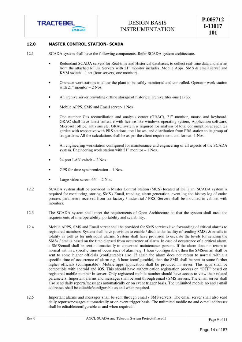
12.0 MASTER CONTROL STATION- SCADA
12.1 SCADA system shall have the following components. Refer SCADA system architecture.
• Redundant SCADA servers for Real-time and Historical databases, to collect real-time data and alarms
from the attached RTUs. Servers with 21” monitor includes, Mobile Apps, SMS & email server and
KVM switch – 1 set (four servers, one monitor).
• Operator workstations to allow the plant to be safely monitored and controlled. Operator work station
with 21” monitor – 2 Nos.
• An archive server providing offline storage of historical archive files-one (1) no.
• Mobile APPS, SMS and Email server- 1 Nos
• One number Gas reconciliation and analysis center (GRAC), 21” monitor, mouse and keyboard.
GRAC shall have latest software with license like windows operating system, Application software,
Microsoft office, antivirus etc. GRAC system is required for analysis of total consumption at each tea
garden with respective with PRS stations, total losses, and distribution from PRS station to its group of
tea gardens. All the calculations shall be as per the client requirement and format- 1 Nos.
• An engineering workstation configured for maintenance and engineering of all aspects of the SCADA
system. Engineering work station with 21” monitor – 1 Nos.
• 24 port LAN switch – 2 Nos.
• GPS for time synchronization – 1 Nos.
• Large video screen 65” – 2 Nos.
12.2 SCADA system shall be provided in Master Control Station (MCS) located at Duliajan. SCADA system is
required for monitoring, storing, SMS / Email, trending, alarm generation, event log and history log of entire
process parameters received from tea factory / industrial / PRS. Servers shall be mounted in cabinet with
monitors.
12.3 The SCADA system shall meet the requirements of Open Architecture so that the system shall meet the
requirements of interoperability, portability and scalability.
12.4 Mobile APPS, SMS and Email server shall be provided for SMS services like forwarding of critical alarms to
registered members. System shall have provision to enable / disable the facility of sending SMSs & emails in
totality as well as for individual alarms. System shall have provision to escalate the levels for sending the
SMSs / emails based on the time elapsed from occurrence of alarm. In case of occurrence of a critical alarm,
a SMS/email shall be sent automatically to concerned maintenance persons. If the alarm does not return to
normal within a specific time of occurrence of alarm e.g. 1 hour (configurable), then the SMS/email shall be
sent to some higher officials (configurable) also. If again the alarm does not return to normal within a
specific time of occurrence of alarm e.g. 6 hour (configurable), then the SMS shall be sent to some further
higher officials (configurable). Mobile apps application shall be provided in server. This apps shall be
compatible with android and iOS. This should have authentication registration process on “OTP” based on
registered mobile number in server. Only registered mobile number should have access to view their related
parameters. Important alarms and messages shall be sent through email / SMS servers. The email server shall
also send daily reports/messages automatically or on event trigger basis. The unlimited mobile no and e-mail
addresses shall be editable/configurable as and when required.
12.5 Important alarms and messages shall be sent through email / SMS servers. The email server shall also send
daily reports/messages automatically or on event trigger basis. The unlimited mobile no and e-mail addresses
shall be editable/configurable as and when required.
Page 14 of 187
DESIGN BASIS
INSTRUMENTATION
P.005712
I-11017
101
Rev.0 AGCL SCADA and Telecom System Project-Phase-II Page 10 of 11
12.6 Mobile apps application shall be provided in server. This apps shall be compatible with android and iOS.
This should have authentication registration process on “OTP” based on registered mobile number in server.
Only registered mobile number should have access to view their related parameters.
12.7 Reconciliation system shall have facility to integration with SCADA system on OPC and collect the required
data for Gas Reconciliation at every level and cumulative total, clearly identifying losses at every stage, Gas
Reconciliation for purchase and sale etc. This shall be done under the guidance of AGCL. Reconciliation
software could also have the facility to feed flow/any process parameter value manually in case of non-
available to require parameters. In totality, this could have online and manual calculation facility. Final result
shall be imported in excel/world format.
12.8 The Gas Pipeline Reconciliation solution shall include all elements necessary to support purchase and sales
agreements, nominations, scheduling, allocation, gas measurement, Gas Reconciliation, invoicing, financial
system (ERP) interface, SCADA system interface, predictive gas quality calculations, and secure user access
for the Commercial Department‘s gas marketing operations, and Gas Quality Monitoring Operations.
12.9 The SCADA system tags shall be decided by vendor. Consideration of SCADA tags shall be adequate
(without adding any hardware to the system) to accommodate 50% future expansion and integration of
existing SCADA system / RTU directly without any limitations and without affecting the various system
performance parameters.
12.10 SCADA shall have OPC (both Client & server) interface for data exchange (read and write) with another
system SCADA system, SAP / any third party interface.
12.11 GPS with antenna and cables, NTP software (client and server) or any compatible software for time
synchronization.
12.12 Redundant LAN
All equipment within the Control Room shall be connected to the SCADA network on redundant LAN. The
redundant LAN consists of two distinct Ethernet segments; each segment has its own dedicated Ethernet
switch. Critical components including SCADA servers, archive servers and workstations shall be provided
with dual Ethernet connections allowing connection to both segments of the LAN. Non-critical items
including printers shall only be connected to a single segment of the redundant LAN.
12.13 KVM Switch: Keyboard, Video and Mouse
For each SCADA system a combined Pull out monitor, keyboard and mouse (KVM) shall be provided. The
KVM Switch shall be located in the SCADA cabinet. This device has an integrated 8 port KVM which shall
be connected to each of the SCADA servers and to the Archive Server.
12.14 SCADA Real Time Server & Historical Server
In Redundant SCADA server, each server shall have independent SCADA license. All the SCADA servers
are of identical in configuration and each server shall be sized of providing full SCADA facilities in the event
of failure of active machine. These SCADA server(s) shall be rack mounted within the SCADA 19 inch
equipment cabinets. SCADA Server fetch the data from RTU, maintain the real time data, history, for
SMS/Email purpose and calculation.
12.15 SCADA Archive Server
This shall be used to prepare reports, to provide historical trend displays, and to provide archived data for
detailed system analysis. The archive server will be located in the SCADA cabinet
For “offline” storage of archive files a Network Attached Storage (NAS) device shall be attached to each
SCADA server. The NAS device provides a high capacity, fast access storage system allowing archive files.
Page 15 of 187
DESIGN BASIS
INSTRUMENTATION
P.005712
I-11017
101
Rev.0 AGCL SCADA and Telecom System Project-Phase-II Page 11 of 11
12.16 Engineer Workstation
Engineering workstation shall have the ability to undertake key system wide engineering functions such as: -
• Configuration of the RTUs networks incl. Programming of devices.
• Database generation, calculations and on line modification.
• HMI graphical development and/or modification.
• Report development and/or modification using MS Excel.
• System network administration.
• System security.
Page 16 of 187
PIPING DESIGN BASIS
P.005712
M-11017
102
ASSAM GAS COMPANY LTD
SCADA AND TELECOM SYSTEM FOR AGCL GAS PIPELINE NETWORK - PAHSE-II
TRACTEBEL ENGINEERING PVT. LTD.
PIPING DESIGN BASIS
DOC. NO. - P.005712-M-11017-102
0 23.01.2019 Release for procurement MK NC SK
Rev. Date Description Prepared By Checked By Approved By
Page 17 of 187
PIPING DESIGN BASIS
P.005712
M-11017
102
Rev.0 AGCL SCADA and Telecom System Project-Phase-II Page 1 of 1
TABLE OF CONTENTS
1.0 SCOPE .................................................................................................................................... 1
2.0 CODES/ STANDARDS AND DOCUMENTS ............................................................................... 1
3.0 PIPELINE NETWORK CONFIGURATION ................................................................................ 4
4.0 DESIGN & ENGINEERING ...................................................................................................... 4
5.0 PIPING DESIGN .................................................................................................................... 4
7.0 WELDING .............................................................................................................................. 9
8.0 TESTING& COMMISSIONING .............................................................................................. 11
ANNEXURE – I ............................................................................................................................... 12
Page 18 of 187
PIPING DESIGN BASIS
P.005712
M-11017
102
Rev.0 AGCL SCADA and Telecom System Project-Phase-II Page 1 of 12
1.0 SCOPE
Refer scope of work P.005712-I-11075-101
2.0 CODES/ STANDARDS AND DOCUMENTS
Latest edition of following Codes &standards are applicable:
ASME Standards
ASME B31.8 Gas transmission and distribution piping systems;
ASME SEC VIII, DIV1 Boiler and Pressure Vessels code;
ASME SEC IX Qualification standard for welding and brazing;
ASME B31.3 Process piping;
ASME B16.10 Face to face and end to end dimensions of valves;
ASME B16.20 Metallic gaskets for pipe flanges – Ring joint, Spiral wound, and jacketed;
ASME B16.25 Butt welding ends;
ASME B16.34 Valves- flanged, threaded and welding end;
ASME B16.5 Pipe flanges and flanged fittings;
ASME B16.47 Large Diameter Steel Flanges
ASME B16.48 Steel line blanks;
ASME B16.9 Factory made wrought butt welding fittings;
ASME B36.10 Welded and seamless wrought steel pipe;
ASTM Standards
ASTM A 53 Pipe, steel, black and hot-dipped zinc coated welded and seamless;
ASTM A 105/A 105 M Forgings, carbon steel, for piping components;
ASTM A 106 Seamless carbon steel pipe for high temperature service;
ASTM A 193/A 193 M Alloy steel and stainless steel bolting materials for high temperature
service;
ASTM A 194/A 194 M Carbon and alloy steel nuts for bolts for high temperature service;
ASTM A 234/A 234 M Piping, fittings of wrought carbon steel and alloy steel for moderate
and elevated temperatures;
ASTM A 320/A 320 M Alloy steel bolting materials for low temperature service;
ASTM A 333/A333 M Seamless and welded steel pipe for low temperature Service;
ASTM A 350/A 350 M Forgings, carbon and low alloy steel, requiring notch toughness
Page 19 of 187
PIPING DESIGN BASIS
P.005712
M-11017
102
Rev.0 AGCL SCADA and Telecom System Project-Phase-II Page 2 of 12
testing for piping components;
ASTM A 352/A 352 M Steel casting, Ferritic and Martenstic, for pressure containing parts,
suitable for low temperature service;
ASTM A 370 Mechanical testing of steel products;
ASTM A 381 Metal-arc-welded steel pipe for use with high-pressure transmission
systems. (Metal are welded);
ASTM A 420/A 420 M Piping fittings of wrought carbon steel and alloy steel for low
temperature service;
ASTM A 694/A 694 M Forgings, carbon and alloy steel, for pipe flanges, fittings, valves,
and parts for high-pressure transmission service;
ASTM A 707/A 707 M Flanges, forged, carbon and alloy steel for low temperature service;
ASTM E 112 Standard methods for determining the average grain size;
API Standards
API 5L Specification for line pipe;
API RP 500 Recommended practice for classification of locations for electrical
installations at petroleum facilities classified as Class I, division I
and division 2;
API RP 505 Recommended practice for classification of locations for electrical
installations at petroleum facilities classified as Class I, zone 0, and
zone 2;
API 605 Large diameter carbon steel flanges;
API 1104 Welding of pipelines and related facilities;
API RP 1102 Steel pipelines crossing railroads& highways;
API 6D Pipeline valves;
API 598 Valve Inspection & Testing
API 6FA Fire Test for Valves
API 607 Fire test for soft seated quarter turn valves;
API RP 5L1 Recommended practice for railroad transportation of line pipe;
MSS Standards
MSS SP 6 Standard Finishes for Contact Faces of Pipe Flanges & Connecting
- End Flanges of Valves & Fittings
MSS SP 25 Standard marking system for valves, fittings, flanges and unions;
MSS SP 44 Steel pipeline flanges;
Page 20 of 187
PIPING DESIGN BASIS
P.005712
M-11017
102
Rev.0 AGCL SCADA and Telecom System Project-Phase-II Page 3 of 12
MSS SP 55 Quality standard for steel castings for valves, flanges and fittings
and other piping components (visual method);
MSS SP 72 Ball Valves with Flanged or Butt welding ends for general service;
MSS SP 75 Specification for high test wrought butt welding fittings;
MSS SP 97 Integrally reinforced forged branch outlet fittings - socket welding,
threaded and butt welding ends;
DIN/EN Standards
EN 10204 Metallic products : types of inspection documents;
EN 10045/1 Metallic products : Charpy impact test - test methods (V and U
notches);
EN 10285 Steel Tube & Fittings for On & Offshore Pipelines- External three
layer extruded polyethylene based coatings;
DIN 30670 Polyethylene coatings for steel pipes and fittings;
ISO Standards
ISO 148 Détermine the impact strength of steel and energyabsorbed by
Charpy V-notch ;
ISO 15590-1 Induction bends, fittings and flanges for pipeline transportation
systems;
ISO 12944 Paints and varnishes – Corrosion protection of steel structures by
protective paintsystems ;
ISO 15741 Paints and varnishes -- Friction-reduction coatings for the interior
of on- and offshore steel pipelines for non-corrosive gases;
ISO 9001 Quality Management Standards ;
BS Standards
BS 5146 Inspection and test of Valves
BS 5351 Steel Ball Valves for the Petroleum, Petrochemical and allied
industries
NACE Standards
MR0175 Sulphide Stress Cracking Resistant Metallic Materials for Oilfield
Equipment;
Oil Industry Safety Directorate (OISD STANDARDS)
OISD 106 Process design and operating philosophies on pressure relief and
disposal system;
OISD 113 Classification of Area for electrical installation at Hydrocarbon and
handling facilities;
OISD 115 Guidelines on Fire Fighting, Equipment and Appliances in
Page 21 of 187
PIPING DESIGN BASIS
P.005712
M-11017
102
Rev.0 AGCL SCADA and Telecom System Project-Phase-II Page 4 of 12
Petroleum Industry;
OISD 118 Layouts for Oil and Gas Installations;
OISD 141 Design and Construction requirement for Cross Country
Hydrocarbon Pipelines;
OISD 163 Process control room safety;
OISD 226 Natural gas transmission pipelines and city gas distribution
networks;
PNGRB (Petroleum& Natural GasRegulatoryBoard)
PNGRB ‘Technical Standards and Specifications including Safety
Standards for Natural Gas Pipelines Regulations’
In case of contradiction, the most stringent shall apply.
3.0 PIPELINE NETWORK CONFIGURATION
Assam Gas Company Ltd., Duliajan transports high pressure and low pressure natural gas through its
transmission and distribution network covering five districts of upper Assam.
The gas is collected presently from sources of OIL and ONGCL. However, gas from other producers may
also be injected into AGCL network as and when available. The compressed gas is transported by dedicated
and common carriers lines to industries such as Brahmaputra Valley Fertilizer Corporation Ltd (BVFCL),
Assam Petrochemical Limited (APL),Namrup Thermal Power Station (NTPS) and uncompressed natural gas
to Lakwa thermal power station (LTPS) and Power Plant of NEEPCO.
The company also supplies low pressure natural gas to over 400 tea factories /industrial consumers spread
over five districts of Upper Assam .At each customer premises, IPRS (Integrated Pressure Reducing Skid) is
installed, which further filters the incoming gas and reduces its pressure to meet individual customers
requirement.
4.0 DESIGN & ENGINEERING
Complete Design and Engineering of the all Piping modification work as summarized in tender
document,including Installation of Flow Control Valves, Isolation Valves, and associated piping, all
associated Instrumentation and Controls with Tubing etc, and complete design, fabrication, installation,
testing & commissioning of all Piping modifications, required for the above changes, shall be carried out by
the Contractor as part of this project.
The Details included in this Tender documents are for information purpose only. However all detailed
engineering work including site survey and supply, fabrication, inspection & testing, installation and
commissioning of all of Piping items, as per project requirements shall be carried out by the Contractor.
4.1. Process Parameters
Refer Process parameters enclosed with tender document
5.0 PIPING DESIGN
5.1. General
All Piping and associated facilities, installed as a part of this project, shall be designed and engineered in
compliance with ASME B31.8, OISD 226 latest edition, PNGRB guidelines and other relevant codes / norms
/ specifications.
Page 22 of 187
PIPING DESIGN BASIS
P.005712
M-11017
102
Rev.0 AGCL SCADA and Telecom System Project-Phase-II Page 5 of 12
Contractor shall carry out design of all Piping, including modification work, for each location separately,
based on design pressure/ temperature rating of the system, applicable process parameters at each station and
applicable standards, drawings and documents, as per project requirement.
All detailed engineering shall be carried out for each location separately, including design, supply,
fabrication, testing, planning of piping modification, pre-fabrication, hot work, inspection and testing and
commissioning of the modified Piping system.
5.2. Project Requirement
The modification work is to be carried out in an existing network in use. All efforts shall be made to
minimize the down time required for modification work and wastage, including the following:
• Where modifications are necessary for installation of instruments, FCVs etc. consideration shall be
given to replacement of entire spool of piping between flanges, valves.
• As far as possible, pre-fabricated assemblies of Piping with FCV, Valves, Instrumentation &Controls
and with necessary piping/Tubing shall be prepared, tested and kept ready for installation, before
beginning modification work on existing Pipelines.
5.3. Station Facilities Design
Installation of FCV& Isolation Valves at Tea Factory : The basic Piping configuration for all Tea Gardens is
shown in the ‘Schematic Drawing’ enclosed with tender documentt.
However detailed design of proposed piping modification required at each location for installation of FCV&
Isolation Valves shall be carried out by the contractor for each location separately based on site survey and
individual site requirements.
All piping shall be adequately supported to prevent undue vibration, deflection or loads on connected
equipment’s. Platform and Crossovers shall be provided for ease of access ,if required.
Equipment/ valves requiring periodic maintenance shall be supported in such a way that the valves and
equipment can be removed with a minimum temporary pipe supports. In the case of 8" and above line size,
support shall be provided immediately below the valves.
Blow down facilities shall be provided for any emergency evacuation of the pipeline, if required.
5.4. Station Piping
All above ground Piping to be installed at all locations, as part of this project, shall be designed in accordance
with the requirements of ASME B31.8 / OISD 226 and other applicable standards/norms.
All piping shall be designed to withstand all installation, testing and operating conditions/loads. Necessary
calculations shall be carried out to verify structural integrity and stability of the piping for the combined
effect of pressure, temperature in all conditions, without over stressing the piping, valves or equipment.
5.4.1. Material and Specifications
All Piping items including Pipes, Valves, Fittings, Flanges, Gaskets, Nuts & Bolts and other misc. items used
in this Project, shall be strictly as per the details given in ‘Piping Material Specification’ Doc No :
PP.005712-M-11097-101, hereinafter collectively referred as the ‘PMS’.
The Material, Ratings, Dimensions, Manufacturing and Testing of all Piping Items, shall be as per the
standards / codes / details listed in the PMS.
The following criteria shall be used for selecting the Piping Class from the PMS :
1. For all locations where Piping of ANSI 150# Pressure Class is required :
Use PMS for – 1C1
Applicable for :
• Piping modification work at all Tea Factories/Industrial consumers.
5.4.2. Pipe Material and Wall Thickness
Page 23 of 187
PIPING DESIGN BASIS
P.005712
M-11017
102
Rev.0 AGCL SCADA and Telecom System Project-Phase-II Page 6 of 12
All pipes used in station piping shall be Seamless pipes of material ASTM A 106 Gr. B.
Pipe wall thickness calculations has been carried out in compliance with ASME B 31.8. Wall thicknesses
used in this project, for all new station Piping, shall strictly be as per the PMS, as summarizes below :
Material & Thickness Summary of Station Piping:
Station Pipes :
• Station pipes material : ASTM A106, Grade B.
Wall Thickness :
o Pipe sizes ½” to 2” NB Pipe - Schedule 80
o Pipe Sizes 3” to 12” NB - Schedule 40
5.4.3. Elbow, Fittings&Flanges
General
All Elbows, Fittings, Flanges and other piping items used in this Project, shall be as per the PMS.
The Material, Ratings, Dimensions, Manufacturing and Testing of all Piping Items, shall be as per the
standards / codes / details listed in the PMS.
Specific Requirements
• Wall thickness for Tees, Elbows, Reducers and Caps shall be determined by vendor as per the
requirements of ASME B 16.9. The thickness calculations shall be approved by client. The mating pipe
details shall betaken as mentioned in the pipe section of the PMS.
• The bore of Weld neck flanges shall match the inside dia of connecting pipe. Pipe thickness shall be as
per the PMS.
Bends
Use of Mitre Bend in new Piping portion in not allowed in this project. Bends shall be provided using
standards elbows, Hot induction bend or Cold Bends.
Hot Induction Bendsshall be made of same material of line pipe with same thickness andaccordance with
ASME B31.8.
Minimum radius allowable for cold field bend shall be 18 D.
Branch Connection
Type of branch connection to be used shall be determined based on Branch Table provided on Sheet 6 of the
PMS.
Steel Butt welding Tees, Reducing Tees, Weldolet and welded branch connection shall be used for
branches,as per the PMS. Reinforcement Pad, if required, shall be of same or equivalent material as pipe, and
thickness as per requirements of ASME B 31.8.
Bolts Nut and Studs
Bolt or Studs Bolts shall be extended completely through the Nuts. Nuts and Bolts shall conform with ASTM
A 194 Gr. 2 H and ASTM A 193 Gr. B 7 respectively.
5.4.4. Valves
All the Ball valves used in this project shall be as per the PMS and Project Datasheets.
All Ball valves& Check valves used in this project shall meet the requirement of API 6D and API 6FA/API
607 for fire safe design. Globe valves shall meet design requirement of BS 1873. Pressure temperature rating
of valves shall be as per ASME B 16.34.
Page 24 of 187
PIPING DESIGN BASIS
P.005712
M-11017
102
Rev.0 AGCL SCADA and Telecom System Project-Phase-II Page 7 of 12
All valves in supply line shall be double block and bleed type and suitable for low temperature application.
Pneumatic test of valve is to be witnessed by TPIA in both fully closed/open condition and passing/leakage is
to be checked. Valve design shall ensure online affirmation of proper seat sealing.
Pup Piece
All Butt Welded Valves shall have pup pieces as per the PMS, datasheet and Tender Specifications. The
thickness of Pup Piece shall be determined by the Vendor as per Code requirements. The pipe end of the Pup
Piece shall match the Mating Pipe. The Mating Pipe details for all Butt Welded valves shall be as given in the
Pipe section of the PMS.
Underground valves, if required at any location due to site constraint, shall have their vent/drain/greasing
points etc, extended above ground along with isolation valves. The vent/drain connection shall have two
valve assemblies, one underground and one above ground and suitable needle plug is to be provided. Fully
welded valves shall be used for underground installation.
Bolted split body valves with flanged connections can be used for above ground pipeline section, however,
the first Isolation Valve on the Mainline shall be Fully Welded (with fully welded body construction), at all
stations.
All manual operated valves up to size 3” shall be wrench operated. Size 4” and above shall be gear operated
with hand wheel (limited to size below 12”).All valves 4” and above shall be Trunnion mounted.
Valves above 6" size shall be equipped with suitable lifting lugs. Tapped holes and eyebolts shall not be used
for lifting lugs.
All the valves of ANSI Class 300 and above shall be 100% radiographed for body andbonnet.All ball valves
of 2" and above shall be trunion mounted. Plug valves should be pressure balanced type.
5.4.5. Station Piping Painting and Colour Code
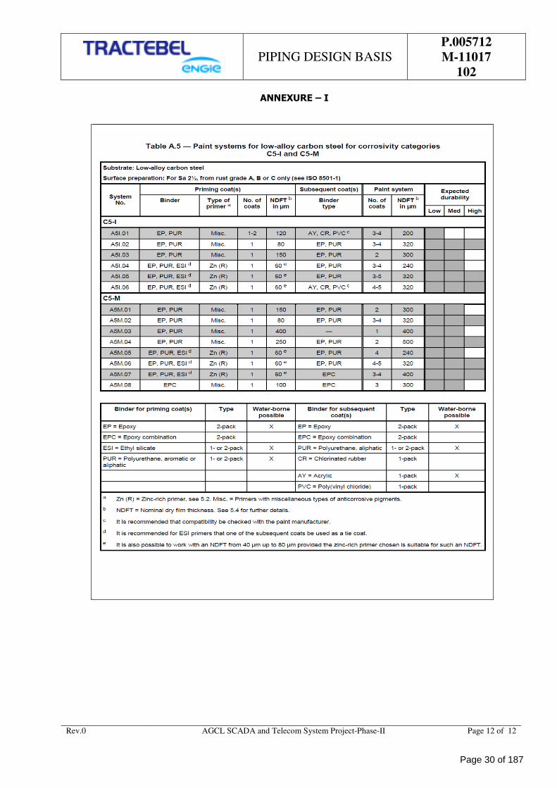
All above ground piping shall be painted to prevent atmospheric corrosion. Painting shall comply to ISO
12944 Part5.
The recommended painting system should be of Category C5 – I Very high (Industrial) as specified in the
Standard ISO 12944 Part 1 to 8. The proposed Painting system shall conform to Table A 5 of ISO 12944 – 5
Standard (Enclosed as Annexure-Ibelow, for Reference).
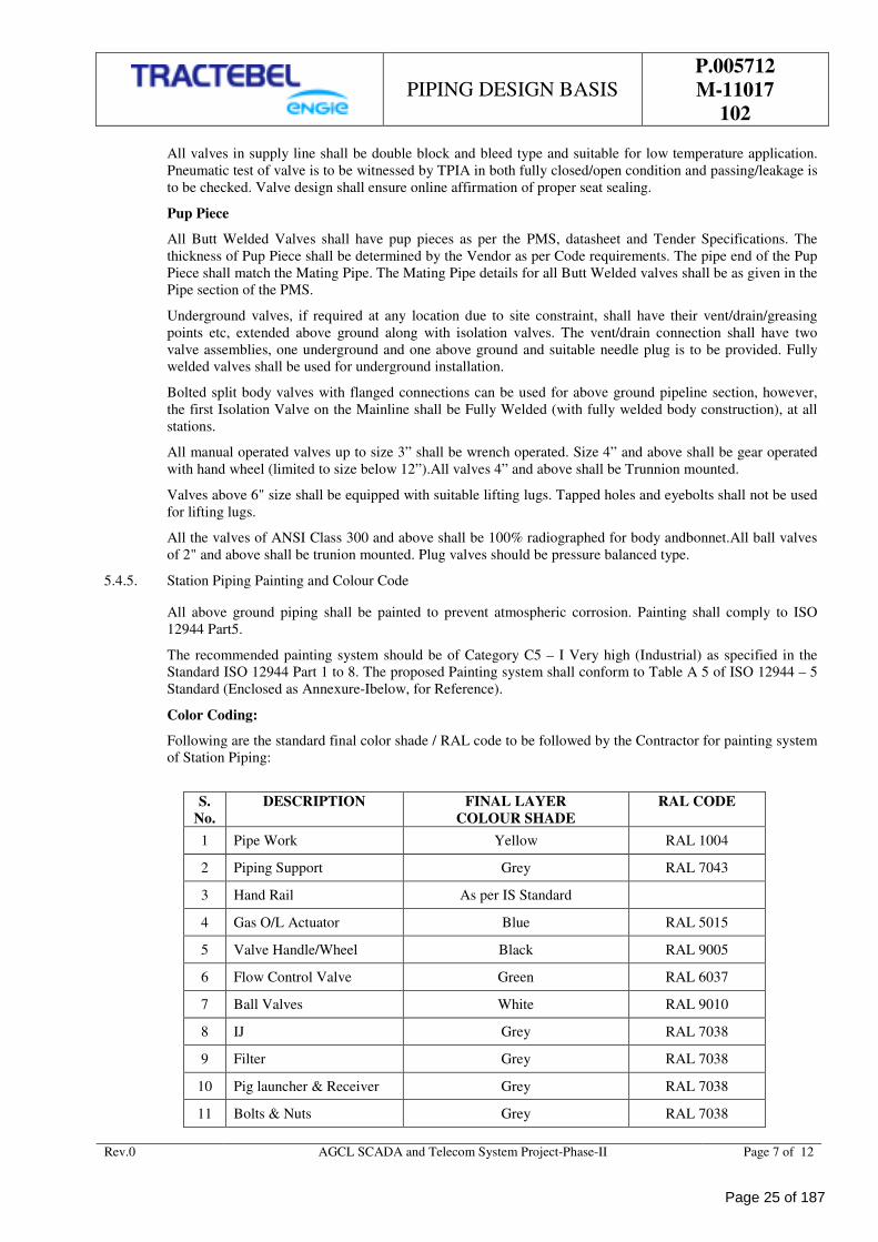
Color Coding:
Following are the standard final color shade / RAL code to be followed by the Contractor for painting system
of Station Piping:
S.
No.
DESCRIPTION FINAL LAYER
COLOUR SHADE
RAL CODE
1 Pipe Work Yellow RAL 1004
2 Piping Support Grey RAL 7043
3 Hand Rail As per IS Standard
4 Gas O/L Actuator Blue RAL 5015
5 Valve Handle/Wheel Black RAL 9005
6 Flow Control Valve Green RAL 6037
7 Ball Valves White RAL 9010
8 IJ Grey RAL 7038
9 Filter Grey RAL 7038
10 Pig launcher & Receiver Grey RAL 7038
11 Bolts & Nuts Grey RAL 7038
Page 25 of 187
PIPING DESIGN BASIS
P.005712
M-11017
102
Rev.0 AGCL SCADA and Telecom System Project-Phase-II Page 8 of 12
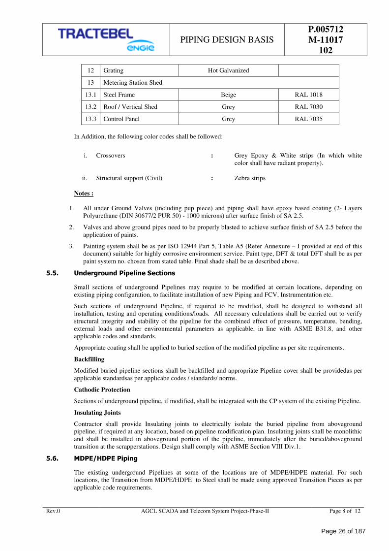
12 Grating Hot Galvanized
13 Metering Station Shed
13.1 Steel Frame Beige RAL 1018
13.2 Roof / Vertical Shed Grey RAL 7030
13.3 Control Panel Grey RAL 7035
In Addition, the following color codes shall be followed:
i. Crossovers : Grey Epoxy & White strips (In which white
color shall have radiant property).
ii. Structural support (Civil) : Zebra strips
Notes :
1. All under Ground Valves (including pup piece) and piping shall have epoxy based coating (2- Layers
Polyurethane (DIN 30677/2 PUR 50) - 1000 microns) after surface finish of SA 2.5.
2. Valves and above ground pipes need to be properly blasted to achieve surface finish of SA 2.5 before the
application of paints.
3. Painting system shall be as per ISO 12944 Part 5, Table A5 (Refer Annexure – I provided at end of this
document) suitable for highly corrosive environment service. Paint type, DFT & total DFT shall be as per
paint system no. chosen from stated table. Final shade shall be as described above.
5.5. Underground Pipeline Sections
Small sections of underground Pipelines may require to be modified at certain locations, depending on
existing piping configuration, to facilitate installation of new Piping and FCV, Instrumentation etc.
Such sections of underground Pipeline, if required to be modified, shall be designed to withstand all
installation, testing and operating conditions/loads. All necessary calculations shall be carried out to verify
structural integrity and stability of the pipeline for the combined effect of pressure, temperature, bending,
external loads and other environmental parameters as applicable, in line with ASME B31.8, and other
applicable codes and standards.
Appropriate coating shall be applied to buried section of the modified pipeline as per site requirements.
Backfilling
Modified buried pipeline sections shall be backfilled and appropriate Pipeline cover shall be providedas per
applicable standardsas per applicabe codes / standards/ norms.
Cathodic Protection
Sections of underground pipeline, if modified, shall be integrated with the CP system of the existing Pipeline.
Insulating Joints
Contractor shall provide Insulating joints to electrically isolate the buried pipeline from aboveground
pipeline, if required at any location, based on pipeline modification plan. Insulating joints shall be monolithic
and shall be installed in aboveground portion of the pipeline, immediately after the buried/aboveground
transition at the scrapperstations. Design shall comply with ASME Section VIII Div.1.
5.6. MDPE/HDPE Piping
The existing underground Pipelines at some of the locations are of MDPE/HDPE material. For such
locations, the Transition from MDPE/HDPE to Steel shall be made using approved Transition Pieces as per
applicable code requirements.
Page 26 of 187
PIPING DESIGN BASIS
P.005712
M-11017
102
Rev.0 AGCL SCADA and Telecom System Project-Phase-II Page 9 of 12
Design of new/modified Piping sections shall be carried out so as to minimize the use of MDPE /HDPE Pipes
and/or fittings in the New/modified section. All new Piping sections planned, shall be of Carbon steel to the
extent possible, and use of MDPE Pipes and fittings in the new/modified sections shall be minimized.
Further, taking branch connection from MDPE/HDPE Pipe shall be avoided, and all branch connections shall
be planned from the Steel Piping section after the Transition Piece. The location of Transition Piece may be
altered, as required, to facilitate installation of steel piping in the new sections.
5.7. Modifications & Restoration
The existing Isolation Valves, in some of the locations are placed in Valve Pits. Similarly, at some of the
locations Piping is covered by civil / brick structures. At all such locations the design shall be carried out to
suit the site requirements, and Piping modifications shall be planned keeping in mind the existing structures.
Demolition of existing structures such as Valve Pits, brick / civil structures covering existing piping shall be
carried out as required for installation of new/modified Piping. The same shall be covered in detail
engineering of the modification activity.
The Valve pits and existing structures, which are demolished shall be restored to their original condition after
Piping modification, to the extent possible, and to the satisfaction of the owner.
Similarly, if excavation of existing Piping / structures is required for modification work, the same shall be
included in detail engineering and planning, and the site shall be restored to its original condition, after
backfilling, to the extent possible.
All demolition, modification, restoration, excavation and backfilling activities required for carrying out the
piping modification work shall be included in detail engineering and shall be carried out as part of the project.
6.0 PURGING
Before cold cutting and welding, ensure there is no hydrocarbon condensate in the piping section. Before
starting of piping modification work purging by nitrogen or any other inert gas must be done to ensure that all
natural gas have removed from piping section /separator.
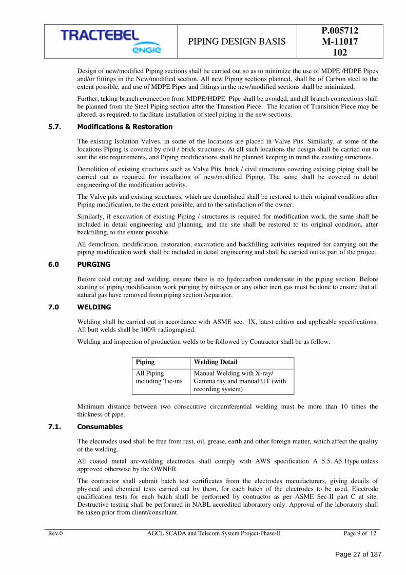
7.0 WELDING
Welding shall be carried out in accordance with ASME sec. IX, latest edition and applicable specifications.
All butt welds shall be 100% radiographed.
Welding and inspection of production welds to be followed by Contractor shall be as follow:
Piping Welding Detail
All Piping
including Tie-ins
Manual Welding with X-ray/
Gamma ray and manual UT (with
recording system)
Minimum distance between two consecutive circumferential welding must be more than 10 times the
thickness of pipe.
7.1. Consumables
The electrodes used shall be free from rust, oil, grease, earth and other foreign matter, which affect the quality
of the welding.
All coated metal arc-welding electrodes shall comply with AWS specification A 5.5. A5.1type unless
approved otherwise by the OWNER.
The contractor shall submit batch test certificates from the electrodes manufacturers, giving details of
physical and chemical tests carried out by them, for each batch of the electrodes to be used. Electrode
qualification tests for each batch shall be performed by contractor as per ASME Sec-II part C at site.
Destructive testing shall be performed in NABL accredited laboratory only. Approval of the laboratory shall
be taken prior from client/consultant.
Page 27 of 187

PIPING DESIGN BASIS
P.005712
M-11017
102
Rev.0 AGCL SCADA and Telecom System Project-Phase-II Page 10 of 12
7.2. Welding Procedure Qualification
Welding procedure qualification shall be in accordance with the relevant requirement of ASME Sec. IX
(latest edition) or other applicable codes and the job requirements. The Contractor shall submit the
proposed welding procedure specification in format as per Pr-WPS Format immediately after the receipt of
the order. Owner’s representative will review, check and approve the welding procedure submitted and shall
release the procedure for qualification test. The complete set of test result as per ASME sec. IX shall
be submitted to the OWNER/ OWNER’s representative for approval immediately after completing the
procedure qualification test and at least 2 weeks before the commencement of actual work. Standard
test specified in the code shall be carried out in all cases. In addition to these test the following test shall be
carried out.
1) Tensile Test
2) Macro/ Micro Examination.
3) Hardness test.
4) Charpy V-notch Impact test at Weld and HAZ
5) Dye Penetrate examination.
These tests shall be carried out on specimens depending upon the type of base material, operating
conditions and requirements laid down in the detailed drawing and specification. It shall be the responsibility
of the Contractor to carry out all the tests required to the satisfaction of the OWNER/ OWNER’s
representative.
7.3. Welder’s Qualification
Welders shall be qualified in accordance with the ASME sec. IX or other applicable codes. It shall be the
responsibility of the Contractor to carry out qualification tests of welders. In addition to NDT testing,
Destructive testing shall also be carried out on welder’s qualification coupon. No welder shall be permitted to
work without the possession of identity card. If a welder is found to perform a type of welding or in a
position for which he is not qualified, he shall be debarred from doing any further work. All welds performed
by an unqualified welder shall be cut and redone by a qualified welder at the expenses of the contractor.
7.4. NON DESTRUCTIVE EXAMINATION
This specification shall govern the basic requirements for Non Destructive Examination (NDE) as it
applies to the fabrication, testing and inspection of all Pressure Piping, and Transmission Piping.
7.4.1 Radiographic Examination
The quality of radiographs shall meet or exceed all requirements of the appropriate International standards
and applicable general specifications. X - Ray is the preferred radiographic method. Use of Gamma ray for
examination is not permitted. Particular attention shall be paid to using radiographic ultra fine grain film
suitable for the application, maintaining correct radiographic geometry during exposure, obtaining correct
density also required by the appropriate standard and the correct placement and exposure of image quality
indicators (IQI's or penetrameters). ASTM wire type IQI's are preferred. The OWNER may permit the use of
ASTM whole type IQI's on a pre-approved basis, provided the NDT CONTRACTOR can
demonstrate satisfactory results. Radiographic technique shall produce maximum contrast and good
definition of IQI wires and shall obtain minimum radiographic density of 2.0 in the weld image. Fluorescent
intensifying screens shall not be used. Max radiographic density shall be 4.0 in all areas of the weld and
parent metal. The inability to view the appropriate wire or hole on any radiograph shall be cause for
automatic rejection of that radiograph which shall be re-radiographed at no expense to the OWNER.
Operator Certification
Radiographers supplied by the CONTRACTOR shall be certified to ASNT Level II, AWS QC] and as per
AWS B1.10 (guide for non-destructive inspection of welds). An operator qualified to ASNT Level I may
assist the Level II operator but all film and sentencing interpretation shall be carried out by a Level ll or
higher operator who shall sign off all report sheets. Visual welding inspection shall be conducted only by a
qualified welding inspector, who shall have a minimum ASNT Level II or AWS (QC. I) CWI or CSWIP 3.1
certification.
Page 28 of 187
PIPING DESIGN BASIS
P.005712
M-11017
102
Rev.0 AGCL SCADA and Telecom System Project-Phase-II Page 11 of 12
The OWNER shall review and approve all QA/QC personnel prior to deployment on the project.
7.4.2 Magnetic Particle Inspection (WPI)
MPT shall be carried out in accordance with the requirements of ASME. Section V. Article 7, & Section VIII
DIV 1, Appendix 6. And as modified by this specification. AC electromagnetic yokes shall be used. A
background of white contrast paint shall be usedin conjunction with a black magnetic ink (wet particle). The
technique shall be carried out in the continuous mode and two examinations shall be carried out at right
angles to cover for both transverse and longitudinal defects. There shall be sufficient overlap to allow 100%
coverage. All unacceptable or spurious indications found by this method shall be investigated and
removed by grinding followed by thickness check.
7.4.3 Dye Penetrate Inspection (DPI)
DPI shall be carried out accordance with the requirements of ASME BPV, Section V, Article 6, & ASME
Section VIII DIV 1, Appendix 8, and as modified by this specification. Unless requested otherwise,
DPI shall be carried out using the solvent removable method. If necessary welds may be lightly dressed
to facilitate DPI testing or to assist in the interpretation of any indications. All unacceptable or spurious
indications found by this method shall be investigated and removed by grinding followed by thickness
check.
7.4.4 Ultrasonic Weld Examination (Ut)
Ultrasonic operators supplied by the NDE CONTRACTOR shall be certified to a General Standards
Board (ASNT/PCN) approved by the OWNER.
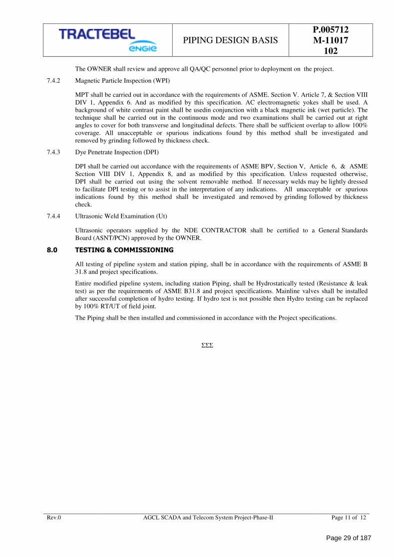
8.0 TESTING & COMMISSIONING
All testing of pipeline system and station piping, shall be in accordance with the requirements of ASME B
31.8 and project specifications.
Entire modified pipeline system, including station Piping, shall be Hydrostatically tested (Resistance & leak
test) as per the requirements of ASME B31.8 and project specifications. Mainline valves shall be installed
after successful completion of hydro testing. If hydro test is not possible then Hydro testing can be replaced
by 100% RT/UT of field joint.
The Piping shall be then installed and commissioned in accordance with the Project specifications.
ΣΣΣ
Page 29 of 187
PIPING DESIGN BASIS
P.005712
M-11017
102
Rev.0 AGCL SCADA and Telecom System Project-Phase-II Page 12 of 12
ANNEXURE – I
Page 30 of 187
MATERIAL REQUISITION
P.005712
I-11071
101
ASSAM GAS COMPANY LTD
SCADA AND TELECOM SYSTEM FOR AGCL GAS PIPELINE
NETWORK - PAHSE-II
TRACTEBEL ENGINEERING PVT. LTD.
MATERIAL REQUISITION
RERT
DOC. NO. P.005712-I-11071-101
0 23.01.2019 Release for Procurement MA SHD SK
Rev. Date Subject of revision Prepared By Checked By Approved By
Page 31 of 187
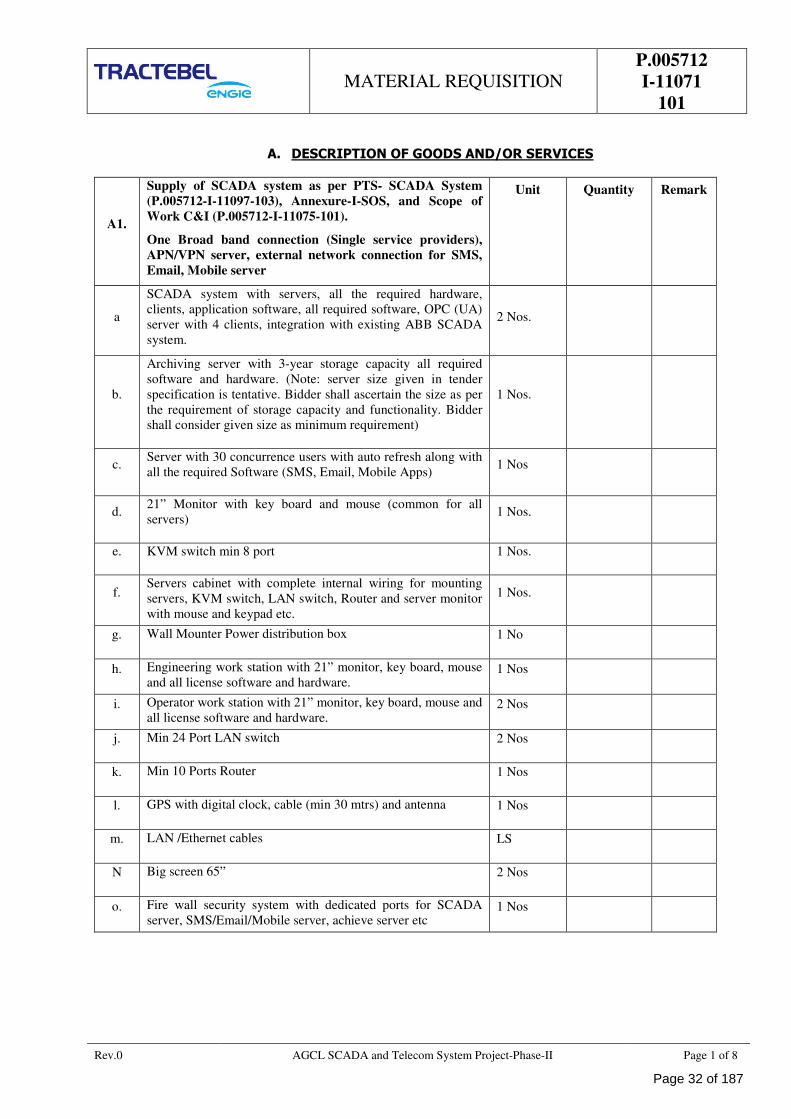
MATERIAL REQUISITION
P.005712
I-11071
101
Rev.0 AGCL SCADA and Telecom System Project-Phase-II Page 1 of 8
A. DESCRIPTION OF GOODS AND/OR SERVICES
A1.
Supply of SCADA system as per PTS- SCADA System
(P.005712-I-11097-103), Annexure-I-SOS, and Scope of
Work C&I (P.005712-I-11075-101).
One Broad band connection (Single service providers),
APN/VPN server, external network connection for SMS,
Email, Mobile server
Unit Quantity Remark
a
SCADA system with servers, all the required hardware,
clients, application software, all required software, OPC (UA)
server with 4 clients, integration with existing ABB SCADA
system.
2 Nos.
b.
Archiving server with 3-year storage capacity all required
software and hardware. (Note: server size given in tender
specification is tentative. Bidder shall ascertain the size as per
the requirement of storage capacity and functionality. Bidder
shall consider given size as minimum requirement)
1 Nos.
c. Server with 30 concurrence users with auto refresh along with
all the required Software (SMS, Email, Mobile Apps) 1 Nos
d. 21” Monitor with key board and mouse (common for all
servers) 1 Nos.
e. KVM switch min 8 port 1 Nos.
f. Servers cabinet with complete internal wiring for mounting
servers, KVM switch, LAN switch, Router and server monitor
with mouse and keypad etc.
1 Nos.
g. Wall Mounter Power distribution box 1 No
h. Engineering work station with 21” monitor, key board, mouse
and all license software and hardware. 1 Nos
i. Operator work station with 21” monitor, key board, mouse and
all license software and hardware. 2 Nos
j. Min 24 Port LAN switch 2 Nos
k. Min 10 Ports Router 1 Nos
l. GPS with digital clock, cable (min 30 mtrs) and antenna 1 Nos
m. LAN /Ethernet cables LS
N Big screen 65” 2 Nos
o. Fire wall security system with dedicated ports for SCADA
server, SMS/Email/Mobile server, achieve server etc 1 Nos
Page 32 of 187
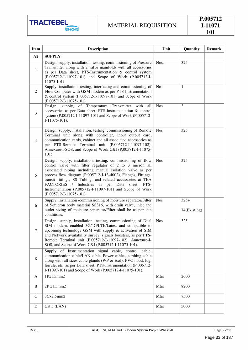
MATERIAL REQUISITION
P.005712
I-11071
101
Rev.0 AGCL SCADA and Telecom System Project-Phase-II Page 2 of 8
Item Description Unit Quantity Remark
A2 SUPPLY
1
Design, supply, installation, testing, commissioning of Pressure
Transmitter along with 2 valve manifolds with all accessories
as per Data sheet, PTS-Instrumentation & control system
(P.005712-I-11097-101) and Scope of Work (P.005712-I-
11075-101)
Nos. 325
2
Supply, installation, testing, interfacing and commissioning of
Flow Computer with GSM modem as per PTS-Instrumentation
& control system (P.005712-I-11097-101) and Scope of Work
(P.005712-I-11075-101)
No 1
3
Design, supply, of Temperature Transmitter with all
accessories as per Data sheet, PTS-Instrumentation & control
system (P.005712-I-11097-101) and Scope of Work (P.005712-
I-11075-101).
Nos. 3
4
Design, supply, installation, testing, commissioning of Remote
Terminal unit along with controller, input output card,
communication cards, cabinet and all associated accessories as
per PTS-Remote Terminal unit (P.005712-I-11097-102),
Annexure-I-SOS, and Scope of Work C&I (P.005712-I-11075-
101).
Nos 325
5
Design, supply, installation, testing, commissioning of flow
control valve with filter regulator of 2 to 3 micron all
associated piping including manual isolation valve as per
process flow diagram (P.005712-J-13-4002), Flanges, Fittings,
transit fittings, SS Tubing, and related accessories at TEA
FACTORIES / Industries as per Data sheet, PTS-
Instrumentation (P.005712-I-11097-101) and Scope of Work
(P.005712-I-11075-101).
Nos 325
6
Supply, installation /commissioning of moisture separator/Filter
of 5-micron body material SS316, with drain valve, inlet and
outlet sizing of moisture separator/Filter shall be as per site
conditions.
Nos 325+
74(Existing)
7
Design, supply, installation, testing, commissioning of Dual
SIM modem, enabled 3G/4G/LTE/Latest and compatible to
upcoming technology GSM with supply & activation of SIM
and Network availability survey, signals boosters, as per PTS-
Remote Terminal unit (P.005712-I-11097-102), Annexure-I-
SOS, and Scope of Work C&I (P.005712-I-11075-101).
Nos 325
8
Supply of Instrumentation signal cable, control cable,
communication cable/LAN cable, Power cables, earthing cable
along with all sizes cable glands (WP & Exd), PVC hood, lug,
ferrule, etc as per Data sheet, PTS-Instrumentation (P.005712-
I-11097-101) and Scope of Work (P.005712-I-11075-101).
A 1Px1.5mm2 Mtrs 2600
B 2P x1.5mm2 Mtrs 8200
C 3Cx2.5mm2 Mtrs 7500
D Cat 5 (LAN) Mtrs 5000
Page 33 of 187
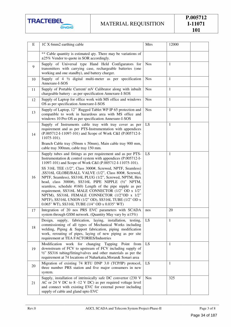
MATERIAL REQUISITION
P.005712
I-11071
101
Rev.0 AGCL SCADA and Telecom System Project-Phase-II Page 3 of 8
E 1C X 6mm2 earthing cable Mtrs 12000
** Cable quantity is estimated qty. There may be variations of
±25% Vendor to quote in SOR accordingly.
9 Supply of Universal type Hand Held Configurators for
transmitters with carrying case, rechargeable batteries (one
working and one standby), and battery charger.
Nos 1
10 Supply of 4 ½ digital multi-meter as per specification
Annexure-I-SOS
Nos 1
11 Supply of Portable Current/ mV Calibrator along with inbuilt
chargeable battery - as per specification Annexure-I-SOS
Nos 1
12 Supply of Laptop for office work with MS office and windows
OS as per specification Annexure-I-SOS
Nos 1
13 Supply of Laptop, 12’’ Rugged Tablet WP IP 65 protection and
compatible to work in hazardous area with MS office and
windows 10 Pro OS as per specification Annexure-I-SOS
Nos 1
14
Supply of Instruments cable tray with tray cover as per
requirement and as per PTS-Instrumentation with appendices
(P.005712-I-11097-101) and Scope of Work C&I (P.005712-I-
11075-101).
Branch Cable tray (50mm x 50mm), Main cable tray 900 mm,
cable tray 300mm, cable tray 150 mm.
LS 1
16
Supply tubes and fittings as per requirement and as per PTS-
Instrumentation & control system with appendices (P.005712-I-
11097-101) and Scope of Work C&I (P.005712-I-11075-101).
SS 316L TEE (1/2”, Class 3000#, Screwed, NPTF, Seamless)
,SS316L GLOBE/BALL VALVE (1/2”, Class 800#, Screwed,
NPTF, Seamless), SS316L PLUG (1/2”, Screwed, NPTM, Hex
head, class 3000#), SS316L PIPE NIPPLE (½” NPTM,
seamless, schedule #160) Length of the pipe nipple as per
requirement, SS316L MALE CONNECTOR (1/2" OD x 1/2"
NPTM), SS316L FEMALE CONNECTOR (1/2”OD x 1/2”
NPTF), SS316L UNION (1/2” OD), SS316L TUBE (1/2" OD x
0.065" WT), SS316L TUBE (1/4" OD x 0.035" WT)
LS 1
17 Integration of 20 nos PRS EVC parameters with SCADA
system through GSM network. (Quantity May vary by ±15%)
nos 20
18
Design, supply, fabrication, laying, installation, testing,
commissioning of all types of Mechanical Works including
welding, Piping & Support fabrication, piping modification
work, rerouting of pipes, laying of new piping as per site
requirement at TEA FACTORIES/Industries
LS 1
19
Modification work for changing Tapping Point from
downstream of FCV to upstream of FCV including supply of
½” SS316 tubing/fitting/valves and other materials as per the
requirement at 74 locations of Naharkatia,Moran& Sonari area
LS 1
20 Migration of existing 74 RTU DNP 3.0 (TCP/IP) protocol,
three number PRS station and five major consumers in new
system.
LS 1
21
Supply, installation of intrinsically safe DC convertor (230 V
AC or 24 V DC to 8 -12 V DC) as per required voltage level
and connect with existing EVC for external power including
supply of cable and gland upto EVC
Nos 325
Page 34 of 187
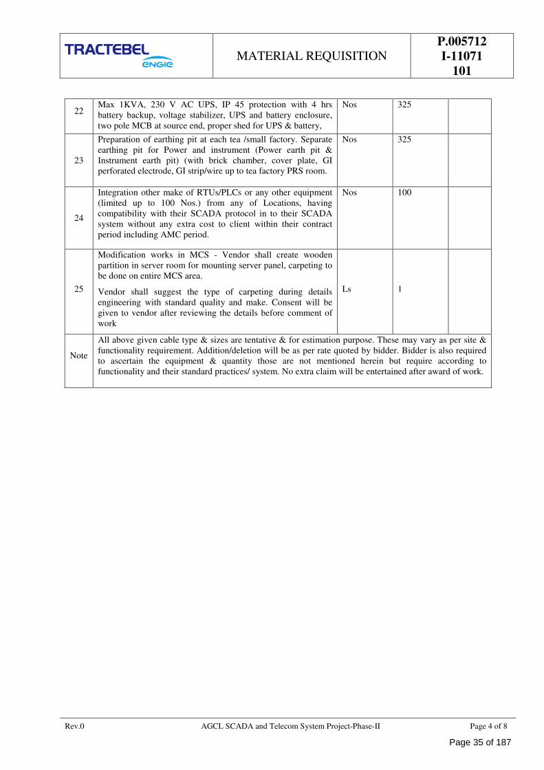
MATERIAL REQUISITION
P.005712
I-11071
101
Rev.0 AGCL SCADA and Telecom System Project-Phase-II Page 4 of 8
22 Max 1KVA, 230 V AC UPS, IP 45 protection with 4 hrs
battery backup, voltage stabilizer, UPS and battery enclosure,
two pole MCB at source end, proper shed for UPS & battery,
Nos 325
23
Preparation of earthing pit at each tea /small factory. Separate
earthing pit for Power and instrument (Power earth pit &
Instrument earth pit) (with brick chamber, cover plate, GI
perforated electrode, GI strip/wire up to tea factory PRS room.
Nos 325
24
Integration other make of RTUs/PLCs or any other equipment
(limited up to 100 Nos.) from any of Locations, having
compatibility with their SCADA protocol in to their SCADA
system without any extra cost to client within their contract
period including AMC period.
Nos 100
25
Modification works in MCS - Vendor shall create wooden
partition in server room for mounting server panel, carpeting to
be done on entire MCS area.
Vendor shall suggest the type of carpeting during details
engineering with standard quality and make. Consent will be
given to vendor after reviewing the details before comment of
work
Ls 1
Note
All above given cable type & sizes are tentative & for estimation purpose. These may vary as per site &
functionality requirement. Addition/deletion will be as per rate quoted by bidder. Bidder is also required
to ascertain the equipment & quantity those are not mentioned herein but require according to
functionality and their standard practices/ system. No extra claim will be entertained after award of work.
Page 35 of 187
MATERIAL REQUISITION
P.005712
I-11071
101
Rev.0 AGCL SCADA and Telecom System Project-Phase-II Page 5 of 8
B. REMARKS / COMMENTS
1.0 GENERAL NOTES
VENDOR's compliance
Vendor shall submit his bid in full compliance with the requirements of this MR and attachments.
Vendor must include the following statement in his bid:
We certify that our bid is fully complying with your enquiry No.: dated……………, and
referenced…………………..
Compliance with this material requisition in any instance shall not relieve the Vendor of his responsibility
to meet the specified performance.
2.0 COMPLIANCE WITH SPECIFICATION
The VENDOR shall be completely responsible for the design, materials, fabrication, testing, inspection,
preparation for shipment and transport of the item strictly in accordance with the Material Requisition and
all attachments thereto.
3.0 VENDOR'S SCOPE
Vendor's scope of work includes all the items with its internals and accessories as shown on the data sheets,
specifications and all unmentioned parts necessary for a satisfactory operation.
4.0 INSPECTION
Vendor shall appoint anyone of the following TPIA for inspection purpose.
a) Lloyd Register of Industrial Services
b) TUV NORD
c) DNV-GL
d) Bureau Veritas (BV)
e) SGS
f) American Bureau Services (ABS).
g) Applus Velosi
h) Vincotte
Apart from inspection by TPIA, inspection shall also be performed by CLIENT and / or its authorised
representative as set out and specified in the codes and particular documents forming this MR.
5.0 APPLICABLE DOCUMENTS
General prescriptions, requirements and information are listed in annex C of this Material Requisition.
6.0 VENDOR'S DOCUMENTS
Vendor shall submit the documentation as listed under point D of this Material Requisition.
All documents shall be submitted in English language.
Page 36 of 187
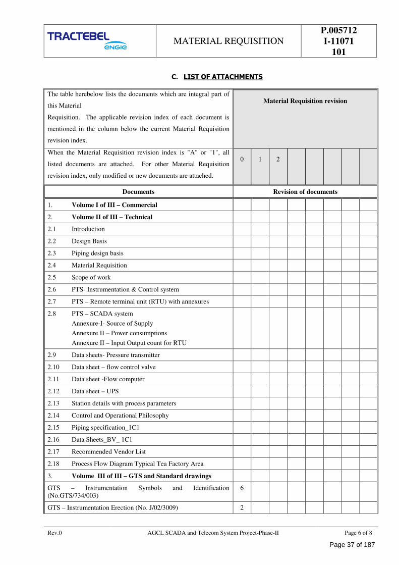
MATERIAL REQUISITION
P.005712
I-11071
101
Rev.0 AGCL SCADA and Telecom System Project-Phase-II Page 6 of 8
C. LIST OF ATTACHMENTS
The table herebelow lists the documents which are integral part of
this Material
Requisition. The applicable revision index of each document is
mentioned in the column below the current Material Requisition
revision index.
Material Requisition revision
When the Material Requisition revision index is "A" or "1", all
listed documents are attached. For other Material Requisition
revision index, only modified or new documents are attached.
0 1 2
Documents Revision of documents
1. Volume I of III – Commercial
2. Volume II of III – Technical
2.1 Introduction
2.2 Design Basis
2.3 Piping design basis
2.4 Material Requisition
2.5 Scope of work
2.6 PTS- Instrumentation & Control system
2.7 PTS – Remote terminal unit (RTU) with annexures
2.8 PTS – SCADA system
Annexure-I- Source of Supply
Annexure II – Power consumptions
Annexure II – Input Output count for RTU
2.9 Data sheets- Pressure transmitter
2.10 Data sheet – flow control valve
2.11 Data sheet -Flow computer
2.12 Data sheet – UPS
2.13 Station details with process parameters
2.14 Control and Operational Philosophy
2.15 Piping specification_1C1
2.16 Data Sheets_BV_ 1C1
2.17 Recommended Vendor List
2.18 Process Flow Diagram Typical Tea Factory Area
3. Volume III of III – GTS and Standard drawings
GTS – Instrumentation Symbols and Identification
(No.GTS/734/003)
6
GTS – Instrumentation Erection (No. J/02/3009) 2
Page 37 of 187
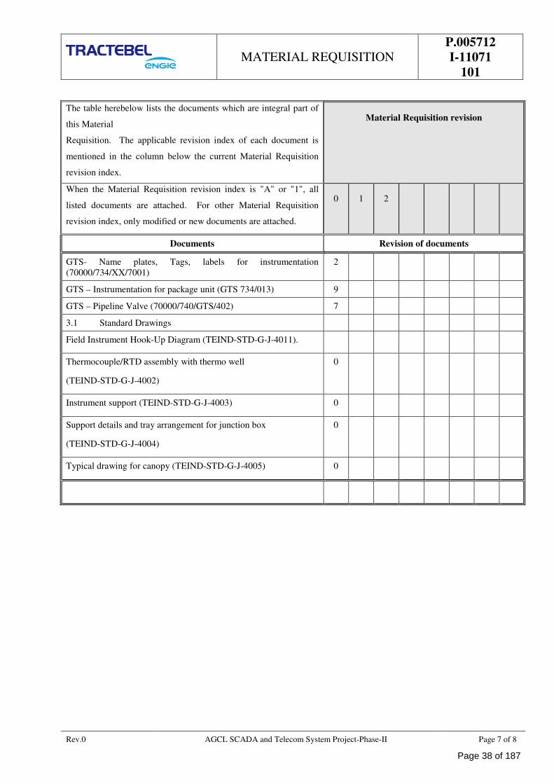
MATERIAL REQUISITION
P.005712
I-11071
101
Rev.0 AGCL SCADA and Telecom System Project-Phase-II Page 7 of 8
The table herebelow lists the documents which are integral part of
this Material
Requisition. The applicable revision index of each document is
mentioned in the column below the current Material Requisition
revision index.
Material Requisition revision
When the Material Requisition revision index is "A" or "1", all
listed documents are attached. For other Material Requisition
revision index, only modified or new documents are attached.
0 1 2
Documents Revision of documents
GTS- Name plates, Tags, labels for instrumentation
(70000/734/XX/7001)
2
GTS – Instrumentation for package unit (GTS 734/013) 9
GTS – Pipeline Valve (70000/740/GTS/402) 7
3.1 Standard Drawings
Field Instrument Hook-Up Diagram (TEIND-STD-G-J-4011).
Thermocouple/RTD assembly with thermo well
(TEIND-STD-G-J-4002)
0
Instrument support (TEIND-STD-G-J-4003) 0
Support details and tray arrangement for junction box
(TEIND-STD-G-J-4004)
0
Typical drawing for canopy (TEIND-STD-G-J-4005) 0
Page 38 of 187
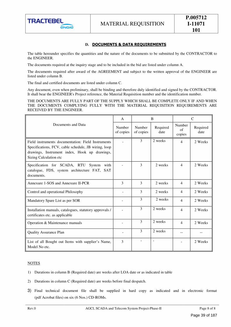
MATERIAL REQUISITION
P.005712
I-11071
101
Rev.0 AGCL SCADA and Telecom System Project-Phase-II Page 8 of 8
D. DOCUMENTS & DATA REQUIREMENTS
The table hereunder specifies the quantities and the nature of the documents to be submitted by the CONTRACTOR to
the ENGINEER.
The documents required at the inquiry stage and to be included in the bid are listed under column A.
The documents required after award of the AGREEMENT and subject to the written approval of the ENGINEER are
listed under column B.
The final and certified documents are listed under column C.
Any document, even when preliminary, shall be binding and therefore duly identified and signed by the CONTRACTOR.
It shall bear the ENGINEER's Project reference, the Material Requisition number and the identification number.
THE DOCUMENTS ARE FULLY PART OF THE SUPPLY WHICH SHALL BE COMPLETE ONLY IF AND WHEN
THE DOCUMENTS COMPLYING FULLY WITH THE MATERIAL REQUISITION REQUIREMENTS ARE
RECEIVED BY THE ENGINEER.
Documents and Data
A B C
Number
of copies
Number
of copies
Required
date
Number
of
copies
Required
date
Field instruments documentation: Field Instruments
Specifications, FCV, cable schedule, JB wiring, loop
drawings, Instrument index, Hook up drawings,
Sizing Calculation etc
- 3 2 weeks 4 2 Weeks
Specification for SCADA, RTU System with
catalogue, FDS, system architecture FAT, SAT
documents.
- 3 2 weeks 4 2 Weeks
Annexure 1-SOS and Annexure II-PCR 3 3 2 weeks 4 2 Weeks
Control and operational Philosophy - 3 2 weeks 4 2 Weeks
Mandatory Spare List as per SOR - 3 2 weeks 4 2 Weeks
Installation manuals, catalogues, statutory approvals /
certificates etc. as applicable
- 3 2 weeks 4 2 Weeks
Operation & Maintenance manuals - 3 2 weeks 4 2 Weeks
Quality Assurance Plan - 3 2 weeks -- --
List of all Bought out Items with supplier’s Name,
Model No etc.
3 - - - 2 Weeks
NOTES
1) Durations in column B (Required date) are weeks after LOA date or as indicated in table
2) Durations in column C (Required date) are weeks before final despatch.
3) Final technical document file shall be supplied in hard copy as indicated and in electronic format
(pdf Acrobat files) on six (6 Nos.) CD-ROMs.
Page 39 of 187
SCOPE OF WORKS
P.005712
I-11075
101
ASSAM GAS COMPANY LTD
SCADA AND TELECOM SYSTEM FOR AGCL GAS PIPELINE NETWORK - PAHSE-II
TRACTEBEL ENGINEERING PVT. LTD.
SCOPE OF WORK
DOC. NO. P.005712 -I-11075-101
0 23.01.2019 Release for Procurement MA SHD SK
Rev. Date Subject of revision Prepared By Checked By Approved By
Page 40 of 187
SCOPE OF WORKS
P.005712
I-11075
101
Rev.0 AGCL SCADA and Telecom System Project-Phase-II page I of I
TABLE OF CONTENTS
1.0 GENERAL .............................................................................................................................. 1
2.0 DEFINITIONS ....................................................................................................................... 1
3.0 APPLICABLE CODES & STANDARDS ..................................................................................... 2
4.0 STATUTORY APPROVALS / CERTIFICATES (AFTER GETTING ORDER) ................................ 4
5.0 REFERENCE .......................................................................................................................... 5
6.0 SITE CONDITIONS ............................................................................................................... 5
7.0 POWER SUPPLY .................................................................................................................... 6
8.0 PROJECT BRIEF .................................................................................................................... 6
9.0 SCOPE OF WORK .................................................................................................................. 8
10.0 SCOPE MATRIX ................................................................................................................... 10
11.0 GENERAL TECHNICAL REQUIREMENTS ............................................................................. 14
12.0 QUALITY ASSURANCE AND QUALITY CONTROL ................................................................ 16
13.0 DESIGN PRINCIPLES.......................................................................................................... 16
14.0 DRAWINGS AND DOCUMENTATIONS ................................................................................ 18
15.0 INSTRUMENTATION WIRING ............................................................................................ 19
16.0 INSTRUMENT INSTALLATION PHILOSOPHY ..................................................................... 20
17.0 INSTALLATION MATERIAL ................................................................................................. 21
18.0 INSTALLATION AND COMMISSIONING ............................................................................. 23
19.0 TESTING AND CALIBRATION ............................................................................................. 24
20.0 SPARE QUANTITY ............................................................................................................... 25
Page 41 of 187
SCOPE OF WORKS
P.005712
I-11075
101
Rev.0 AGCL SCADA and Telecom System Project-Phase-II Page 1 of 26
1.0 GENERAL
1.1 Bidder shall submit their offer in a well-documented manner with all required documents as listed in
“Material Requisition” (but not limited to) of this tender document.
1.2 The language of bidder’s offer including catalogue, technical literature or any other documents or any
software shall be English language only. This shall be applicable for bought out items also.
1.3 Scope of the bidder shall be as per the “Scope of Work”. Any other activities not specifically mentioned
/covered in the tender documents but otherwise required for satisfactory completion /safety of work has to
be carried out by the contractor within specified schedule at no extra cost to owner.
1.4 Bidder shall strictly follow the Recommended Vendor List attached with the tender document for various
items.
1.5 This document shall read in conjunction with material requisition and other specification enclosed with
tender document.
2.0 DEFINITIONS
Subject to the requirements of the context, the terms (hereafter listed in alphabetical order) used in this
specification are given the following meaning:
AGREEMENT Designates the agreement concluded between the CLIENT and
the CONTRACTOR, under which the latter undertakes to the
former the GOODS and/or SERVICES according to the
stipulations which are agreed and specified in the form of an
order.
CLIENT Designates the purchaser of the GOODS and/or SERVICES
which are the subject of the AGREEMENT.
CONTRACTOR Designates the individual or legal entity with whom the order has
been concluded by the CLIENT. The term "CONTRACTOR"
may be used indifferently for a supplier, a manufacturer, an
erection contractor, etc.
DAYS - WEEKS – MONTHS Specify the number of calendar days, weeks or months and not of
working days, weeks or months.
ENGINEER Designates the individual or legal entity to which the CLIENT
has entrusted various tasks in relation with the carrying out of his
PROJECT
GOODS and/or SERVICES Designate, depending on the case, all or part of the drawings or
documents, substances, materials, materiel, equipment,
structures, plant, tools, machinery to be studied, designed,
manufactured, supplied, erected, built, assembled, adapted,
arranged or put into service by the CONTRACTOR under the
AGREEMENT, including all the studies, tasks, works and
services specified by the order. The Terms GOODS or
SERVICES may by indifferently used one for the other as
required by the context.
PROJECT Designates the aggregate of GOODS and/or SERVICES to be
provided by one or more CONTRACTORS.
Page 42 of 187
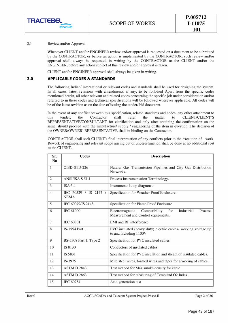
SCOPE OF WORKS
P.005712
I-11075
101
Rev.0 AGCL SCADA and Telecom System Project-Phase-II Page 2 of 26
2.1 Review and/or Approval
Whenever CLIENT and/or ENGINEER review and/or approval is requested on a document to be submitted
by the CONTRACTOR, or before an action is implemented by the CONTRACTOR, such review and/or
approval shall always be requested in writing by the CONTRACTOR to the CLIENT and/or the
ENGINEER, before any action subject of this review and/or approval is taken.
CLIENT and/or ENGINEER approval shall always be given in writing.
3.0 APPLICABLE CODES & STANDARDS
The following Indian/ international or relevant codes and standards shall be used for designing the system.
In all cases, latest revisions with amendments, if any, to be followed Apart from the specific codes
mentioned herein, all other relevant and related codes concerning the specific job under consideration and/or
referred to in these codes and technical specifications will be followed wherever applicable. All codes will
be of the latest revision as on the date of issuing the tender/ bid document.
In the event of any conflict between this specification, related standards and codes, any other attachment to
this tender, the Contractor shall refer the matter to CLIENT/CLIENT’S
REPRESENTATIVE/CONSULTANT for clarification and only after obtaining the confirmation on the
same, should proceed with the manufacture/ supply / engineering of the item in question. The decision of
the OWNER/OWNER’ REPRESENTATIVE shall be binding on the Contractor.
CONTRACTOR shall seek CLIENT's final interpretation of any conflicts prior to the execution of work.
Rework of engineering and relevant scope arising out of underestimation shall be done at no additional cost
to the CLIENT.
Sr.
No
Codes Description
1 OISD-STD-226 Natural Gas Transmission Pipelines and City Gas Distribution
Networks.
2 ANSI/ISA S 51.1 Process Instrumentation Terminology.
3 ISA 5.4 Instruments Loop diagrams.
4 IEC 60529 / IS 2147 /
NEMA
Specification for Weather Proof Enclosure.
5 IEC 60079/IS 2148 Specification for Flame Proof Enclosure
6 IEC 61000 Electromagnetic Compatibility for Industrial Process
Measurement and Control equipments.
7 IEC 60801 EMI and RF interference
8 IS-1554 Part 1 PVC insulated (heavy duty) electric cables- working voltage up
to and including 1100V.
9 BS-5308 Part 1, Type 2 Specification for PVC insulated cables.
10 IS 8130 Conductors of insulated cables
11 IS 5831 Specification for PVC insulation and sheath of insulated cables.
12 IS-3975 Mild steel wires, formed wires and tapes for armoring of cables.
13 ASTM D 2843 Test method for Max smoke density for cable
14 ASTM D 2863 Test method for measuring of Temp and O2 Index.
15 IEC 60754 Acid generation test
Page 43 of 187
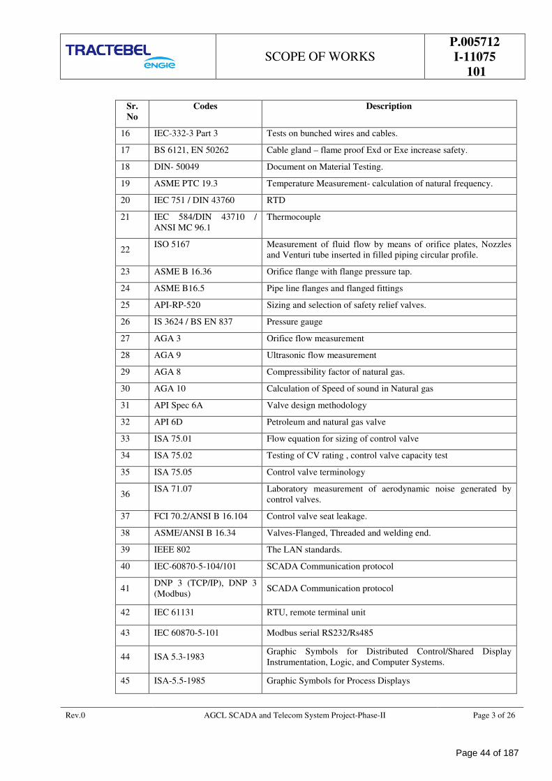
SCOPE OF WORKS
P.005712
I-11075
101
Rev.0 AGCL SCADA and Telecom System Project-Phase-II Page 3 of 26
Sr.
No
Codes Description
16 IEC-332-3 Part 3 Tests on bunched wires and cables.
17 BS 6121, EN 50262 Cable gland – flame proof Exd or Exe increase safety.
18 DIN- 50049 Document on Material Testing.
19 ASME PTC 19.3 Temperature Measurement- calculation of natural frequency.
20 IEC 751 / DIN 43760 RTD
21 IEC 584/DIN 43710 /
ANSI MC 96.1
Thermocouple
22 ISO 5167 Measurement of fluid flow by means of orifice plates, Nozzles
and Venturi tube inserted in filled piping circular profile.
23 ASME B 16.36 Orifice flange with flange pressure tap.
24 ASME B16.5 Pipe line flanges and flanged fittings
25 API-RP-520 Sizing and selection of safety relief valves.
26 IS 3624 / BS EN 837 Pressure gauge
27 AGA 3 Orifice flow measurement
28 AGA 9 Ultrasonic flow measurement
29 AGA 8 Compressibility factor of natural gas.
30 AGA 10 Calculation of Speed of sound in Natural gas
31 API Spec 6A Valve design methodology
32 API 6D Petroleum and natural gas valve
33 ISA 75.01 Flow equation for sizing of control valve
34 ISA 75.02 Testing of CV rating , control valve capacity test
35 ISA 75.05 Control valve terminology
36 ISA 71.07 Laboratory measurement of aerodynamic noise generated by
control valves.
37 FCI 70.2/ANSI B 16.104 Control valve seat leakage.
38 ASME/ANSI B 16.34 Valves-Flanged, Threaded and welding end.
39 IEEE 802 The LAN standards.
40 IEC-60870-5-104/101 SCADA Communication protocol
41 DNP 3 (TCP/IP), DNP 3
(Modbus) SCADA Communication protocol
42 IEC 61131 RTU, remote terminal unit
43 IEC 60870-5-101 Modbus serial RS232/Rs485
44 ISA 5.3-1983 Graphic Symbols for Distributed Control/Shared Display
Instrumentation, Logic, and Computer Systems.
45 ISA-5.5-1985 Graphic Symbols for Process Displays
Page 44 of 187
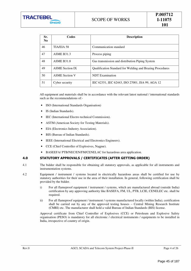
SCOPE OF WORKS
P.005712
I-11075
101
Rev.0 AGCL SCADA and Telecom System Project-Phase-II Page 4 of 26
Sr.
No
Codes Description
46 TIA/EIA 58 Communication standard
47 ASME B31.3 Process piping
48 ASME B31.8 Gas transmission and distribution Piping System
49 ASME Section IX Qualification Standard for Welding and Brazing Procedures
50 ASME Section V NDT Examination
51 Cyber security IEC 62351, IEC 62443, ISO 27001, ISA 99, AGA 12
All equipment and materials shall be in accordance with the relevant latest national / international standards
such as the recommendations of:-
• ISO (International Standards Organisation)
• IS (Indian Standards).
• IEC (International Electro technical Commission).
• ASTM (American Society for Testing Materials).
• EIA (Electronics Industry Association).
• BIS (Bureau of Indian Standards).
• IEEE (International Electrical and Electronics Engineers).
• CCE (Chief Controller of Explosives, Nagpur).
• BASEEFA/ PTB/NEC/EN/FM/CENELAC for hazardous area application.
4.0 STATUTORY APPROVALS / CERTIFICATES (AFTER GETTING ORDER)
4.1 The bidder shall be responsible for obtaining all statutory approvals, as applicable for all instruments and
instrumentation systems.
4.2 Equipment / instrument / systems located in electrically hazardous areas shall be certified for use by
statutory authorities for their use in the area of their installation. In general, following certification shall be
provided by the bidder.
i) For all flameproof equipment / instrument / systems, which are manufactured abroad (outside India)
certification by any approving authority like BASEFA, FM, UL, PTB, LCIE, CENELEC etc. shall be
required.
ii) For all flameproof equipment / instrument / systems manufactured locally (within India), certification
shall be carried out by any of the approved testing houses – Central Mining Research Institute
(CMRI) etc. The manufacturer shall hold a valid Bureau of Indian Standards (BIS) license.
Approval certificate from Chief Controller of Explosives (CCE) or Petroleum and Explosive Safety
organisation (PESO) is mandatory for all electronic / electrical instruments / equipments to be installed in
India, irrespective of country of origin.
Page 45 of 187
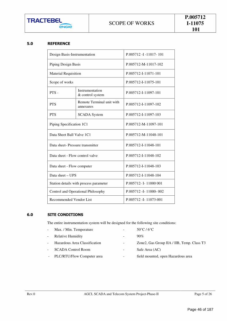
SCOPE OF WORKS
P.005712
I-11075
101
Rev.0 AGCL SCADA and Telecom System Project-Phase-II Page 5 of 26
5.0 REFERENCE
Design Basis-Instrumentation P.005712 -I -11017- 101
Piping Design Basis P.005712-M-11017-102
Material Requisition P.005712-I-11071-101
Scope of works P.005712-I-11075-101
PTS - Instrumentation
& control system P.005712-I-11097-101
PTS Remote Terminal unit with
annexures P.005712-I-11097-102
PTS SCADA System P.005712-I-11097-103
Piping Specification 1C1 P.005712-M-11097-101
Data Sheet Ball Valve 1C1 P.005712-M-11048-101
Data sheet- Pressure transmitter P.005712-I-11048-101
Data sheet - Flow control valve P.005712-I-11048-102
Data sheet - Flow computer P.005712-I-11048-103
Data sheet – UPS P.005712-I-11048-104
Station details with process parameter P.005712- I- 11000 001
Control and Operational Philosophy P.005712 -I- 11000- 002
Recommended Vendor List P.005712 -I- 11073-001
6.0 SITE CONDITIONS
The entire instrumentation system will be designed for the following site conditions:
- Max. / Min. Temperature - 50°C / 6°C
- Relative Humidity - 90%
- Hazardous Area Classification - Zone2, Gas Group IIA / IIB, Temp. Class T3
- SCADA Control Room - Safe Area (AC)
- PLC/RTU/Flow Computer area - field mounted, open Hazardous area
Page 46 of 187
SCOPE OF WORKS
P.005712
I-11075
101
Rev.0 AGCL SCADA and Telecom System Project-Phase-II Page 6 of 26
7.0 POWER SUPPLY
7.1 Normal Power: 230 V ± 20%, 50Hz ± 5 %, AC power is available at tea factory/ industrial
consumers/industrial consumers
7.2 Any other control supply from 230 V AC to 24 V DC/12VDC or 48 V DC to 24 V DC or 48 V DC to 230 V
AC as required, will be converted in their panel by the contractor.
7.3 Client will arrange Non-UPS Electrical power supply from factory at one point inside the factory. Vendor
shall put one MCB at sources end and carry the power to the required place. If any other voltage levels are
required, then all necessary conversions shall be in the scope of CONTRACTOR.
7.4 Components of power supply system shall be of highest quality available for reliability and long service
life. Power supplies for all transmitters, controllers, signal converters, electric system and components in the
system shall be supplied from uninterruptible power supplies.
7.5 Protective fuses shall be of indicating cartridge type mounted in fuse holders.
8.0 PROJECT BRIEF
8.1 Existing Facility
AGCL desires to connect total 325 nos. of Tea Factories with SCADA facility. Following facilities are
available in tea factory
a) Inlet Isolation valve (AGCL Battery limit)
b) Filter separator (By tea factory)
c) Pressure reduction skid (by tea factory)
d) Turbine flow meter (by tea factory)
e) Electronic volume corrector (EVC) battery operated of two different makes
• Vemtech with passive RS 232 and RS 485 ports
• Corous (Itron) with Passive RS 232 ports
Note: Availability and Workability of communication port in EVC shall be ensured by M/s AGCL.
Communication port shall be tested by M/s AGCL in presence of vendor. Vendor’s responsibility is to
interface with RTU
f) 230 V AC ± 20%, non-UPS power supply by tea factory
g) All above facilities are kept under tea factory custodian shed called as “PRS ROOM”
8.2 New Facility By Vendor
a. FLOW CONTROL VALVE
Flow control valve shall be with smart positioner, pressure gauges & filter with pressure regulator,
moisture separator/Filter upto 5-micron etc
Flow Control valves shall be connected with RTU through control cable. Natural gas from Pipeline
shall be used as operating media to operate the control valves. Tap off for Actuation to FCV shall be
tapped from upstream of FCV. Natural gas may carry few amount of moisture contain, therefore
moisture separator/Filter just after tap-off isolation shall be provided. Control valve shall have isolation
valves at upstream and downstream, for removal of control valve in case of any breakdown or
maintenance. Necessary piping modification work shall be carried out by contractor for installation of
control valves / isolation valves. Refer typical process flow diagram enclosed with this document.
This shall be installed parallel to the existing station Isolation valve. Existing inlet valve shall be used
as bypass valve and shall be kept closed with lock or with spectacle blind with sealing provision to
avoid tampering. Existing inlet valve shall be used only in case of maintenance of flow control valve.
Sizing of Flow control valve shall be done based on maximum / agreed gas quantity requirement at
Page 47 of 187
SCOPE OF WORKS
P.005712
I-11075
101
Rev.0 AGCL SCADA and Telecom System Project-Phase-II Page 7 of 26
each tea factory. Control Valve of different tea factories shall be designed case to case basis as per
specific process parameters. Design of the control valve shall be carried out for 150% of maximum /
agreed quantity (as per requirement of AGCL).
b. SCADA SYSTEM
A Centralized SCADA system for monitoring, controlling and data acquisition shall be implemented at
AGCL Office, Duliajan with dedicated telecom network. Project objective is to control the gas flow to
tea factories as per desired quantity and also to permit the customer to withdraw more gas within 150%
of the agreed quantity for the factories by changing the set point from SCADA, in case upstream
pressure is sufficient at pressure regulating station.
c. REMOTE TERMINAL UNIT (RTU)
Remote Terminal unit (RTU) with dual SIM 3G/4G/LTE /Latest & compatible to upcoming technology
GSM modem
RTU for interfacing with pressure transmitter, FCV(Hardwire) and Existing EVC (modbus). RTU
cabinet Ex “d” and wall/ stand mounted inside the “PRS Room”
At each tea factory, turbine flow meter is available with EVC. Existing turbine flow meter with EVC
shall be connected with RTU on MODBUS Protocol. Flow meter reading and all the necessary
parameters as available in the EVC shall be recorded in RTU. Flow meter reading shall be used for
controlling the gas flow. All the data of EVC shall also be transmitted to SCADA via
telecommunication system.
Natural gas is being used by tea factories for tea processing whereas in some of the tea factories,
natural gas is also being utilized for running the gas-based power generators. Turbine gas flow meters
with EVC are available in both the lines. Wherever flow meter is not available in generator line, AGCL
will provide turbine flow meter with EVC.
The tap-off for gas-based generator shall be from downstream of newly proposed flow control valve.
However, the consumption pattern of gas generator is fixed, hence in order to maintain the tea factory
consumption, input to flow controller shall be the summation of both the flow meters and set point shall
be the desired quantity to the tea factory plus the fix flow to the gas-based power generator.
d. PRESSURE TRANSMITTER
Pressure transmitter for monitoring inlet pressure with two valve manifold, mounting stand, SS tubing,
SS valves & fittings
e. 230 V AC UPS
Max 1KVA, 230 V AC UPS, IP 45 protection with 4 hrs battery backup, voltage stabilizer, UPS and
battery enclosure, two pole MCB at source end, proper shed for UPS & battery, UPS shall be kept 15
meters away from tea factory PRS room.
f. EARTHING PIT
Power earthing pit and instrument earthing pit with brick chamber, cover plate, GI perforated electrode,
GI strip/wire upto tea factory PRS room.
g. CABLES
Power cable, signals cables, LAN cable, communication cable with cable tray, GI conduct for LAN
cable, cable gland etc
• Power cable 3C x 2.5mm2
• Signals cable 1P/2P x 1.5mm2
• LAN cable
h. EXTERNAL POWER SUPPLY TO EXISTING ELECTRONIC VOLUME CORRECTOR (EVC)
Page 48 of 187
SCOPE OF WORKS
P.005712
I-11075
101
Rev.0 AGCL SCADA and Telecom System Project-Phase-II Page 8 of 26
At present EVC is working on battery. EVC shall be used for flow controlling purpose of FCV. In order
to do so, a continuous data feedback is required to RTU. Therefore, vendor scope shall be to provide
external intrinsically safe DC power supply convertor compatible to voltage requirement of EVC and
also compatible to DC voltage convertor for communication port and interconnect to EVC. It is
vendor’s responsibility to interact with existing EVC OEM for necessary requirement. While cable
glanding, vendor shall ensure that Ex”d” property of EVC should not be disturb. Therefore, gland and
cable size shall be compatible to entry size available in EVC.
9.0 SCOPE OF WORK
9.1 The Contractor’s scope of work shall include but not limited to the following:
9.2 Scope of work shall comprise of Project Management and execution including, System Design, Detail
Engineering, Procurement of Materials, manufacturing, fabrication, Supply, Installation, Inspection &
Factory Acceptance Testing (total Equipment & System Integration) & Testing of system of SCADA, RTU,
wireless Telecom , flow control valves etc as per Material requisition & SOR including Packaging,
forwarding, Insurance, Shipping related all formalities, Inland Transportation to site, and Supply of all
related goods including Mandatory, Commissioning consumables spares, Handling, Storage & Safe
custody, Supply of all type of Erection Items, site engineering, Pre-Commissioning activity, Testing,
Interconnection and interfacing, Trial Run, Commissioning, Training, support and Warranty Including any
civil works etc., & documentation of total system, Test certificates, calibration certificates of equipment
required to complete in all respect.
9.3 Contractor shall collect all the necessary existing system documents and information require for interfacing
with their system. It is contractor’s responsibility to interact or co-ordinate with existing equipment supplier
for technical details require for interface with existing system and RTU.
9.4 SCADA vendor shall supply, install, integrate, configure and commission all software and hardware
equipment like RTU, Servers, Switches Routers, firewalls, installation materials computers, Operators
consoles with controller and panels and workstation, printers laptop etc.
9.5 Successful bidder shall conduct site survey, access feasibility works, execution strategy, service provider
network availability survey, collect longitude, latitude, altitude (GSP coordinates) for geographic map, co-
ordination with service provider and collect all required data and submit report to client for commencement
of work.
9.6 Contractor shall carry all the required Tools and Tackles require for installation, erection, testing and
commissioning of system. Quantities of all the tools and tackles shall be adequate and certified as per the
quantum and quality to work. These quantities may require to enhance as and when required by Client to
achieve the project schedule or to expedite the progress.
9.7 Contractor shall also carry all the calibration equipment/ testing equipment like multi-meter, hand held
calibrator, 4-20mA simulator, modbus simulators, diagnostic tools etc.
9.8 Supply and laying of power, signals, control and communication cables, earthing cables including supply,
laying of cable tray including terminations, ferruling, cable numbering, marking, testing including hot &
cold loop testing. Branch cable shall be laid in cable tray and cable from Junction box or field local panel
shall be buried.
9.9 Note –Contractor shall choose the cable size and type according to requirement, but cable size and type of
the cables shall be according to PTS- Instrumentation & control system only.
9.10 Contractor shall carry out design, sizing, calculations, supply, testing, inspection, installation,
commissioning and handing over the flow control valve with all associated Piping, fittings, flanges, and
control valve accessories (like E/P convertor with Smart positioner, filter regulator, SS tubing, SS fittings,
SS isolation valves etc) , transit fittings and associated isolation valves, as per tender specification.
9.11 Contractor shall carry out design, supply, testing, inspection, installation, commissioning and handing over
the smart pressure transmitter. Pressure transmitter shall be installed at the gas inlet of each tea
factory/industrial consumers. Supply of pressure transmitter along with two valve manifold, SS isolation
valve, SS tubes, SS fittings (as per tender specification and bill of material shall be in contractors scope.
Page 49 of 187
SCOPE OF WORKS
P.005712
I-11075
101
Rev.0 AGCL SCADA and Telecom System Project-Phase-II Page 9 of 26
9.12 Required masonry works for installation of systems and all associated equipment etc. shall be in
contractor’s scope of supply. Any damage occurred in the existing PRS building of tea factory/ industrial
consumers during installation of equipment shall be repaired by contractor
9.13 Any other equipment /material not specifically mentioned herein but required to complete the work (i.e. to
install, commission and successfully run the Installation) shall be in contractor’s scope.
9.14 Contractor shall prepare, maintain and submit inspection reports, erection/installation progress reports,
material log etc. periodically.
9.15 Daily/Weekly progress report, Documentation like procedure preparation and approval, furnish of
inspection reports, handing over the documents after completion of project etc shall be done by contractor at
their cost.
9.16 Preparation of cable drum cutting schedule, cable schedule/interfacing wiring diagram, branch cable tray
routine is in contractor scope.
9.17 Supply, Fabrication and installation of MS base frames, supports, pipes, plates etc. for RTU including
welding, bolting, riveting, supply of necessary anchor bolts, grouting etc., supply of paint and applying one
coat of anti-rust primer and two finished coats of approved synthetic enamel paint, breaking walls, floors
etc. for structures as required and supply of all GI hardware materials as required
9.18 Supply, fabrication and installation of base frame for UPS with proper shed including welding, bolting,
grouting etc with supply of paint and applying one coat of anti-rust primer and two finished coats of
approved synthetic enamel paint.
9.19 Contractor shall supply the material as per recommended vendor list. If any item is not covered under
recommended vendor list, shall take written approval of CLIENT/CLIENT’S REPRESENTATIVE before
supply of material.
9.20 Unloading of material/equipment related to works received at site shall be in the contractor’s scope.
9.21 Inspection of received material by unpacking/opening boxes at site including spares & material to be
received at site in presence of CLIENT/CLIENT’S REPRESENTATIVE in charge/OEM.
9.22 Contractor shall follow Quality and Safety requirement during construction phases of the Project.
9.23 Any special training for height work, electrical/mechanical safety, Scaffolding work, special toolbox, etc.,
for workers, promotional programs, motivational programs etc., shall be in contractor’s scope.
9.24 The existing underground pipelines at some of the locations are of MDPE/HDPE material. For such
locations, the transition from MDPE/HDPE to steel shall be made using approved transition pieces as per
applicable code requirements.
9.25 Design of new/modified piping sections shall be carried out so as to minimize the use of MDPE /HDPE
pipes and/or fittings in the new/modified section. All new piping sections planned, shall be of carbon steel
to the extent possible, and use of MDPE pipes and fittings in the new/modified sections shall be minimized.
9.26 Further, taking branch connection from MDPE/HDPE pipe shall be avoided, and all branch connections
shall be planned from the steel piping section after the transition piece. The location of transition piece may
be altered, as required, to facilitate installation of steel piping in the new sections.
Page 50 of 187
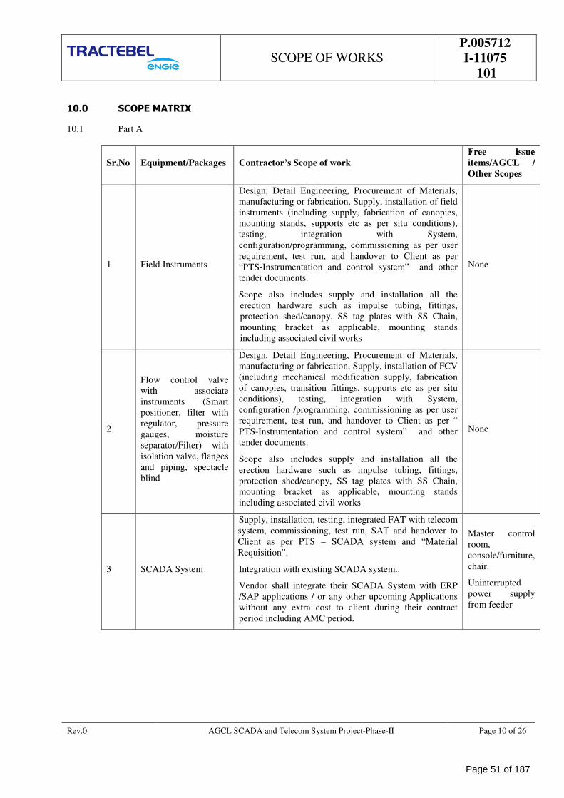
SCOPE OF WORKS
P.005712
I-11075
101
Rev.0 AGCL SCADA and Telecom System Project-Phase-II Page 10 of 26
10.0 SCOPE MATRIX
10.1 Part A
Sr.No Equipment/Packages Contractor’s Scope of work
Free issue
items/AGCL /
Other Scopes
1 Field Instruments
Design, Detail Engineering, Procurement of Materials,
manufacturing or fabrication, Supply, installation of field
instruments (including supply, fabrication of canopies,
mounting stands, supports etc as per situ conditions),
testing, integration with System,
configuration/programming, commissioning as per user
requirement, test run, and handover to Client as per
“PTS-Instrumentation and control system” and other
tender documents.
Scope also includes supply and installation all the
erection hardware such as impulse tubing, fittings,
protection shed/canopy, SS tag plates with SS Chain,
mounting bracket as applicable, mounting stands
including associated civil works
None
2
Flow control valve
with associate
instruments (Smart
positioner, filter with
regulator, pressure
gauges, moisture
separator/Filter) with
isolation valve, flanges
and piping, spectacle
blind
Design, Detail Engineering, Procurement of Materials,
manufacturing or fabrication, Supply, installation of FCV
(including mechanical modification supply, fabrication
of canopies, transition fittings, supports etc as per situ
conditions), testing, integration with System,
configuration /programming, commissioning as per user
requirement, test run, and handover to Client as per “
PTS-Instrumentation and control system” and other
tender documents.
Scope also includes supply and installation all the
erection hardware such as impulse tubing, fittings,
protection shed/canopy, SS tag plates with SS Chain,
mounting bracket as applicable, mounting stands
including associated civil works
None
3 SCADA System
Supply, installation, testing, integrated FAT with telecom
system, commissioning, test run, SAT and handover to
Client as per PTS – SCADA system and “Material
Requisition”.
Integration with existing SCADA system..
Vendor shall integrate their SCADA System with ERP
/SAP applications / or any other upcoming Applications
without any extra cost to client during their contract
period including AMC period.
Master control
room,
console/furniture,
chair.
Uninterrupted
power supply
from feeder
Page 51 of 187
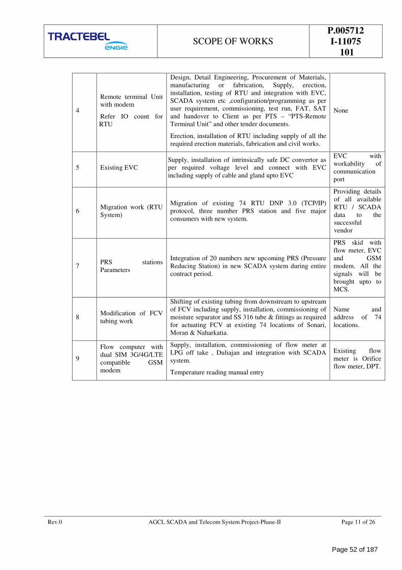
SCOPE OF WORKS
P.005712
I-11075
101
Rev.0 AGCL SCADA and Telecom System Project-Phase-II Page 11 of 26
4
Remote terminal Unit
with modem
Refer IO count for
RTU
Design, Detail Engineering, Procurement of Materials,
manufacturing or fabrication, Supply, erection,
installation, testing of RTU and integration with EVC,
SCADA system etc ,configuration/programming as per
user requirement, commissioning, test run, FAT, SAT
and handover to Client as per PTS – “PTS-Remote
Terminal Unit” and other tender documents.
Erection, installation of RTU including supply of all the
required erection materials, fabrication and civil works.
None
5 Existing EVC
Supply, installation of intrinsically safe DC convertor as
per required voltage level and connect with EVC
including supply of cable and gland upto EVC
EVC with
workability of
communication
port
6 Migration work (RTU
System)
Migration of existing 74 RTU DNP 3.0 (TCP/IP)
protocol, three number PRS station and five major
consumers with new system.
Providing details
of all available
RTU / SCADA
data to the
successful
vendor
7 PRS stations
Parameters
Integration of 20 numbers new upcoming PRS (Pressure
Reducing Station) in new SCADA system during entire
contract period.
PRS skid with
flow meter, EVC
and GSM
modem. All the
signals will be
brought upto to
MCS.
8 Modification of FCV
tubing work
Shifting of existing tubing from downstream to upstream
of FCV including supply, installation, commissioning of
moisture separator and SS 316 tube & fittings as required
for actuating FCV at existing 74 locations of Sonari,
Moran & Naharkatia.
Name and
address of 74
locations.
9
Flow computer with
dual SIM 3G/4G/LTE
compatible GSM
modem
Supply, installation, commissioning of flow meter at
LPG off take , Duliajan and integration with SCADA
system.
Temperature reading manual entry
Existing flow
meter is Orifice
flow meter, DPT.
Page 52 of 187
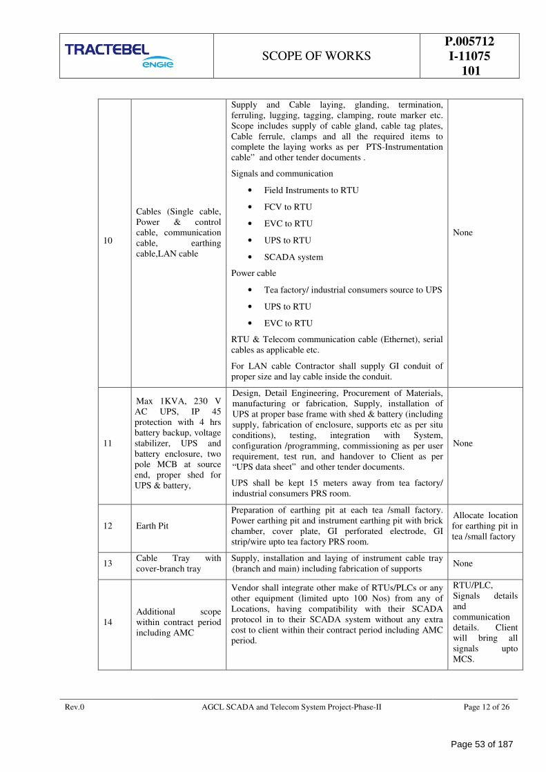
SCOPE OF WORKS
P.005712
I-11075
101
Rev.0 AGCL SCADA and Telecom System Project-Phase-II Page 12 of 26
10
Cables (Single cable,
Power & control
cable, communication
cable, earthing
cable,LAN cable
Supply and Cable laying, glanding, termination,
ferruling, lugging, tagging, clamping, route marker etc.
Scope includes supply of cable gland, cable tag plates,
Cable ferrule, clamps and all the required items to
complete the laying works as per PTS-Instrumentation
cable” and other tender documents .
Signals and communication
• Field Instruments to RTU
• FCV to RTU
• EVC to RTU
• UPS to RTU
• SCADA system
Power cable
• Tea factory/ industrial consumers source to UPS
• UPS to RTU
• EVC to RTU
RTU & Telecom communication cable (Ethernet), serial
cables as applicable etc.
For LAN cable Contractor shall supply GI conduit of
proper size and lay cable inside the conduit.
None
11
Max 1KVA, 230 V
AC UPS, IP 45
protection with 4 hrs
battery backup, voltage
stabilizer, UPS and
battery enclosure, two
pole MCB at source
end, proper shed for
UPS & battery,
Design, Detail Engineering, Procurement of Materials,
manufacturing or fabrication, Supply, installation of
UPS at proper base frame with shed & battery (including
supply, fabrication of enclosure, supports etc as per situ
conditions), testing, integration with System,
configuration /programming, commissioning as per user
requirement, test run, and handover to Client as per
“UPS data sheet” and other tender documents.
UPS shall be kept 15 meters away from tea factory/
industrial consumers PRS room.
None
12 Earth Pit
Preparation of earthing pit at each tea /small factory.
Power earthing pit and instrument earthing pit with brick
chamber, cover plate, GI perforated electrode, GI
strip/wire upto tea factory PRS room.
Allocate location
for earthing pit in
tea /small factory
13 Cable Tray with
cover-branch tray
Supply, installation and laying of instrument cable tray
(branch and main) including fabrication of supports None
14
Additional scope
within contract period
including AMC
Vendor shall integrate other make of RTUs/PLCs or any
other equipment (limited upto 100 Nos) from any of
Locations, having compatibility with their SCADA
protocol in to their SCADA system without any extra
cost to client within their contract period including AMC
period.
RTU/PLC,
Signals details
and
communication
details. Client
will bring all
signals upto
MCS.
Page 53 of 187
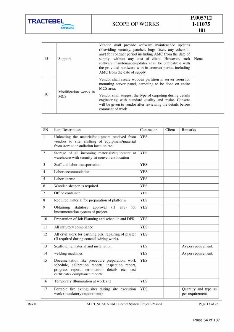
SCOPE OF WORKS
P.005712
I-11075
101
Rev.0 AGCL SCADA and Telecom System Project-Phase-II Page 13 of 26
15 Support
Vendor shall provide software maintenance updates
(Providing security, patches, bugs fixes, any others if
any) for contract period including AMC from the date of
supply, without any cost of client. However, such
software maintenance/updates shall be compatible with
the provided hardware with in contract period including
AMC from the date of supply
None
16 Modification works in
MCS
Vendor shall create wooden partition in server room for
mounting server panel, carpeting to be done on entire
MCS area.
Vendor shall suggest the type of carpeting during details
engineering with standard quality and make. Consent
will be given to vendor after reviewing the details before
comment of work
SN Item Description Contractor Client Remarks
1 Unloading the material/equipment received from
vendors to site, shifting of equipmens/material
from store to installation location etc.
YES
2 Storage of all incoming materials/equipment at
warehouse with security at convenient location
YES
3 Staff and labor transportation YES
4 Labor accommodation. YES
5 Labor license. YES
6 Wooden sleeper as required. YES
7 Office container YES
8 Required material for preparation of platform YES
9 Obtaining statutory approval (if any) for
instrumentation system of project.
YES
10 Preparation of Job Planning and schedule and DPR YES
11 All statutory compliance YES
12 All civil work for earthing pits, repairing of plaster
(If required during conceal wiring work).
YES
13 Scaffolding material and installation YES As per requirement.
14 welding machines YES As per requirement.
15 Documentation like procedure preparation, work
schedule, calibration reports, inspection report,
progress report, termination details etc. test
certificates compliance reports
YES
16 Temporary Illumination at work site YES
17 Portable fire extinguisher during site execution
work (mandatory requirement)
YES Quantity and type as
per requirement
Page 54 of 187
SCOPE OF WORKS
P.005712
I-11075
101
Rev.0 AGCL SCADA and Telecom System Project-Phase-II Page 14 of 26
10.2 P
a
r
t
11.0 GENERAL TECHNICAL REQUIREMENTS
11.1 General site equipments shall be suitable for operation under the following site conditions.
Sand & dust : With a built-up of dust on operational surface to a level such as
may occur because of imperfections in the sealing of equipment,
housing and conditions prevailing in sub- tropical dust conditions.
Tropicalisation : The equipments shall be fully tropicalised.
Shock & vibration : The equipments shall withstand transportation and handling by air,
sea and road under packed conditions.
11.2 The equipments shall also be resistant to termite, fungus, rodents and salty environment. Environmental
Specification of Equipment to be supplied.
11.3 The equipment at Stations shall be designed for non-air conditioned environment and shall perform
satisfactorily under the following conditions.
Activity TEMPERATURE HUMIDITY
Design for 06 to 50°C 90% RH
Storage & transportation 06 to 50°C 90% RH
11.4 The equipment shall also be resistant to termite, fungus, rodents and salty environment. Environmental
Specification of Equipment to be supplied.
11.5 The equipment at Stations shall be designed for non-air conditioned environment.
11.6 Area and zone classification
All the control rooms wherever available are classified as Safe Areas.
All the fields wherever available are classified as Hazardous area.
11.7 Surge Protection, Transient Suppressors, RFI filters Equipments shall be designed with built-in safety to
protect against the effects of monitor induced high voltages.
11.8 Earthing
Transmitters, Junction box and control cabinets shall be provided with earthing lugs. All these lugs/ strips
shall be properly secured to the electrical earthing bus.
All system grounds of various cards and equipment, shields of instrument cables shall be connected to
system ground bus, which is electrically isolated from the AC mains earthing bus. The equipment shall
provide separate earthing strip for the same. The system ground bus shall be connected to independent
ground buses through insulated wires.
The wire and cable shielding are required to prevent the equipment from propagating interference and to
protect the equipment from the effect of interference propagated by other devices. Shielding is typically
floating on the device end, tied to IE at the control console.
Instrument earth (earth resistance less than 5 ohm)
Power earth (earth resistance less than 10 ohms)
Accordingly, the equipments shall provide separate earthing strips as mentioned above.
a. Instrument earth(IE)/system ground
18 Carrying of Nitrogen cylinder to each location for
flashing any residual gas from gas separator prior
to start of welding/grinding works
YES Quantity as per
requirement
Page 55 of 187
SCOPE OF WORKS
P.005712
I-11075
101
Rev.0 AGCL SCADA and Telecom System Project-Phase-II Page 15 of 26
IE earth shall be copper earth. IE ground protects sensitive electrical and electronic device, circuit and
wiring from electromagnetic interference (EMI) and radio frequency interference (RFI). IE should be
free from transient voltages and electromagnetic noise. It is, therefore, normally isolated from PE
ground. Instrument earth should be tied in the most direct possible path to a common earth electrode.
IE grounds resistance is less than 1 ohm to ground
b. Power Earth (PE)/AC mains grounding
PE ground provides a route to dissipate the power line transient to earth potential. PE should be tied in
the most direct possible path to a common earth electrode
PE grounds resistance is less than 10 ohm to ground
11.9 Safety Requirements
It is the intent of the CLIENT that operational hazards be reduced to a minimum. Contractor shall use
sound engineering judgment to complete installation that will perform the required function without
compromise of safety.
All controls shall operate in a fail-safe mode. A fail-safe mode defines what a plant, equipment or system
will do when it fails, so as to ensure a safe condition.
Provision shall be made to isolate all 230 V AC (If any) incoming signals to a cabinet, before gaining access
to cabinet internals. Shrouded terminals with warning labels shall be provided, with these terminals being
segregated from other incoming terminals.
11.10 Electromagnetic Compatibility - EMC
The equipment shall be efficiently screened against EMI, RFI and conductive interference and shall not
interfere with other equipment in the vicinity or installed in the same building.
The equipment shall be required to meet one of the relevant EMC standards (IEC, MIL, VDE, BS, IEEE
etc.).
11.11 The entire electronic component shall be protected from airborne contaminants as per ISA 71.04
environmental conditions/equivalent for process measurement and control system.
11.12 Civil Works
Civil works required for interconnecting cabling between various systems, equipments, telecommunication
system and the power supply unit along with cable routing and dressing.
Associated foundation, grouting for installation of equipment.
Providing and laying perforated trays etc. for point a) above.
Any other masonry work associated with entry and installation of equipment, painting and finishing etc.
Any other civil works not specifically mentioned in the tender but required as per site requirement.
11.13 Electrical Works
Electrical work associated at all the stations shall be consisting of (but not limited to):
All cable work including earthing and system ground earth associated with the installation of the supplied
equipment.
Any temporary electrical works associated with the installation and commissioning of the system.
Testing and certification of all electrical works.
All power cabling works (including supply of cables, glanding, ferruling, termination etc.).
Page 56 of 187
SCOPE OF WORKS
P.005712
I-11075
101
Rev.0 AGCL SCADA and Telecom System Project-Phase-II Page 16 of 26
11.14 Spares
Erection & Commissioning spares
The erection & commissioning spares shall be arranged by the Contractor to cater to the needs / requirement
during installation, commissioning, site acceptance testing, trial run and warranty period. These spares shall
be readily available with the Contractor.
The erection & commissioning spares are different from mandatory spares and Contractor shall not use the
mandatory spares as commissioning spares.
12.0 QUALITY ASSURANCE AND QUALITY CONTROL
Contractor shall be fully responsible for their Quality Assurance and associated Quality Control process.
Unless otherwise agreed by the PURCHASER, the Contractor’s quality system shall meet the requirements
of ISO 9001:2015 Quality System and shall be accredited by a recognized authority.
Contractor is required to establish an acceptable Quality Plan, inclusive of quality manual and procedures
that cover all activities of the order, in order to comply with the Quality System requirements.
Contractor shall be responsible for arranging/liaising with the Third Party Inspection Agency and other
agencies for design appraisal, inspection, survey and certification requirements as required by the
specification/requisition.
When required, waiver and acceptance of non-conformances shall be subjected to Third Party Inspection
Agency approval before CLIENT endorsement. These concession records shall be included in the
Manufacturer’s Final Documentation.
13.0 DESIGN PRINCIPLES
13.1 General
Instrumentation control and monitoring systems shall be in accordance with this specification and as defined
in the P & I Diagrams.
13.2 Instrument Selection
Instruments and instrumentation systems of proven reliability and latest technology shall be used.
Selection of instrumentation shall be made from the recommended vendor list.
Any exception has to be justified and is subject to approval by the CLIENT.
13.3 Tagging
All instruments and instrumentation equipment shall be permanently identified by tags, labels and/or
nameplates. Use of adhesive tapes shall not be allowed.
13.4 Painting
Manufacturer's standard colours shall be used for all instrumentation equipment in control and instrument
rooms, unless otherwise specified.
Field instruments shall generally be epoxy painted, unless otherwise specified.
13.5 Transmission Systems
Transmission of the process variables shall generally be by means of electronic or low level signals. The
output signal for electronic instruments shall be 4 to 20 mA DC or digital or both.
No process fluid/gas shall be piped into the control rooms or the instrument rooms.
Page 57 of 187
SCOPE OF WORKS
P.005712
I-11075
101
Rev.0 AGCL SCADA and Telecom System Project-Phase-II Page 17 of 26
13.6 Enclosures and Materials
All instruments shall be suitable to withstand the environmental conditions specified for the plant location.
All parts of instruments maybe that subject to attack from moisture, fungus growth or insect ought to be
suitably treated (tropicalisation).
Local instrument housings shall be weather-proof (IP 65 minimum) and meet the electrical area
classification requirements.
All parts of instruments exposed to process fluids shall be resistant to corrosion.
13.7 Electronic Instrumentation in Hazardous Areas
In hazardous areas, intrinsically safe instrumentation shall be provided.
If not possible / practical, flameproof protection may also be used wherever applicable.
All electrical instruments to be installed in hazardous locations shall be certified to international Standards.
13.8 Contacts shall be encapsulated, hermetically sealed and, if used in intrinsically safe circuits, contacts shall
be gold plated.
13.9 R.F. Immunity
All instruments and control systems shall be immune from the effects of any R.F. interference that may
occur at the plant location in accordance with IEC 801 "Electromagnetic compatibility for industrial-process
measurement and control equipment".
Equipment to be installed inside the control room shall be in compliance with the IEC/NEC/EU
requirements, denoted by the "approved mark".
Electromagnetic Interference
The offered equipment shall be based on most effective techniques to minimize the effects of
electromagnetic interference. The contractor shall ensure that the electromagnetic interference generated by
the system is well below the permissible levels as per applicable standards.
The equipment shall be required to meet one or more of the following standards:
IEC 801 – 3:1984
BS 6667:PART 3 : 1985
ANSI/ IEEE C 37.1-1989
MIL – STD- 461
VDE 0871
The offered equipment shall be supplied along with certificate of compliance from manufacturer or other
authorised agency. In case bidder is not in a position to provide the above certification, bidder to perform
type test for Electromagnetic Compatibility without any cost implication to the owner.
13.10 Measuring Units
The metric SI system shall be used for all documents. The following units of measurement as well as their
multiples and sub-multiples, shall be used:
Flow
Gas : Sm3/h (15.556OC; 1.01325 bar), MMSCMD
Liquid : m3/h (at flowing temperature)
L/h for flow lower than 0.1 m3/h
Steam, condensate and mass flow : kg/h.
Page 58 of 187
SCOPE OF WORKS
P.005712
I-11075
101
Rev.0 AGCL SCADA and Telecom System Project-Phase-II Page 18 of 26
Pressure
Gauge pressure : kg/cm2 (g) and Bar (g)
Absolute pressure : kg/cm2 (a) and Bar (a)
Differential pressure : kg/cm2, mm of H2O, mm of Hg and milli bar
Level
0 - 100 % (Process)
Temperature
Deg C
Other Measurements
Current: A or mA
Voltage: V or mV
Power: kW
Force: N
Mass: kg or t
Density: kg/m3
Time: d or h or s.
Scales and Charts
Temperature instruments shall have scales calibrated in °C.
Pressure + be 0 - 100 linear.
14.0 DRAWINGS AND DOCUMENTATIONS
14.1 The language used in all correspondence, document, literature, drawings etc., shall be in English language.
14.2 Contractor shall furnish all relevant technical manuals, literature and other technical data as required at the
various stages of the project indicated in MR.
14.3 All the drawings and documents shall be verified by the Contractor before submitting the same for review.
14.4 All the documentation shall be submitted in hard cover loose ring folders in A4 size (210mm x 297 mm) in
3 sets.
14.5 All documents shall also be provided in “SOFT COPY” form.
14.6 Review/approval of documents by CLIENT/CLIENT’S REPRESENTATIVE does not absolve the
Contractor of their responsibilities to satisfactory completion of the project as per the requirements of
contract document. Contractor is required to make necessary rectification in the system to meet the
requirements of the contract document at any stage of system implementation, without additional
implication of cost and schedule to the OWNER.
14.7 It is Contractor’s responsibility to incorporate all the comments of the OWNER’S/OWNER’S
REPRESENTATIVE in the next revision itself. Contractor shall be responsible for incorporation of
additional comments at any stage of the system implementation, without implication of extra cost and
schedule to the Owner. If any comment is not incorporated in the revised document, the same shall be
brought to the notice of the OWNER’S/OWNER’S REPRESENTATIVE with justification for review
before submission of revised documents.
14.8 The review code will be furnished by CLIENT/CLIENT’S REPRESENTATIVE only when the complete
document is furnished by Contractor.
14.9 Contractor shall furnish point wise response to CLIENT/CLIENT’S REPRESENTATIVE comments
Page 59 of 187
SCOPE OF WORKS
P.005712
I-11075
101
Rev.0 AGCL SCADA and Telecom System Project-Phase-II Page 19 of 26
indicating the document section/clause/page no. reference where the same has been included in the revised
document. The body of the document and corresponding pages will show the revision bars only at the
places where the revision has been carried out. CLIENT/CLIENT’S REPRESENTATIVE will be required
to check the revised document w.r.t. these changes only, while considering that rest of the document has
remained unchanged.
14.10 The documents and drawings to be prepared by the contractor are listed hereunder.
Drawings
As a minimum requirement, the following drawings shall be prepared:-
Loop diagrams
Field JB wiring drawings
Instruments Cable schedule
Load consumption for instruments.
Process hook-up drawings common for all locations
Instruments and field JB location layout
DOCUMENTS
Instrument data sheets
The data sheets shall cover all necessary technical data associated with the Instruments as per the enclosed
format.
Calculation sheets
Calculation / sizing sheets for control valve, safety relief valves & WF calculation for thermowell shall be
provided along with data sheet.
Certification files
It shall contain copies of all electrical safety certificates and all documents applicable to the safety of
electrical equipment installed in hazardous areas (e.g. intrinsically safe loop specifications).
Actual power consumption
Station-wise Power Consumption of all electronic instruments.
Cable layout drawings
The cable layout drawings shall show the route of instrument cables and the location of all instrument
junction boxes, local panels, and MCT layout detailed drawings as applicable.
15.0 INSTRUMENTATION WIRING
15.1 Typical Wiring Philosophy
General
a) All field mounted electrical and electronic instruments shall be connected by means of individual
cables to field mounted junction boxes located in each plant area.
b) The field mounted junction boxes shall be provided for the connection of multipair cables and of
individual cables to local instruments if require.
c) Different types of signals shall be segregated into separate junction boxes :
i. Analogue signals.
ii. RTD signals
iii. logic signals
Page 60 of 187
SCOPE OF WORKS
P.005712
I-11075
101
Rev.0 AGCL SCADA and Telecom System Project-Phase-II Page 20 of 26
iv. solenoid valves
v. Power supply.
A further segregation shall be made between intrinsically safe and non-intrinsically safe signals.
d) Multipair cables shall be used between each field mounted instrument junction box and the Master
Terminal Unit (MTU) or the Remote Terminal Units (RTU).
15.2 Typical Cable Installation
Overhead multipair cables
Multipair cables between field junction boxes and MTU or RTU shall run on cable ladders. They shall run
in multiple layers if required. The ladder shall be of adequate width. Separate cable ladders shall be
provided for intrinsically safe cables, non-intrinsically safe cables, instrument power supply cables (230
VAC, 200 VA max).
Overhead field cables
Single pair cables shall run on cable tray when more than 3 cables are run together. They shall run as one
single layer. Where three or less cables are to be run (single circuit cables) from the main cable tray bank,
these shall run in straight lengths of galvanized conduit, size depending on number of cables. No
conduit fittings shall be used. All angles are to be open and the cables may be clipped in angle or in channel
section.
Underground cables
Underground cables shall be laid in trenches. The cable trenches shall be buried with a minimum depth of
600 mm. The route of cable trenches shall avoid above ground and underground obstructions so as to
maintain reasonable access to the cables. Wherever practical, trenches shall run in unpaved areas. Where
cables cross roads they shall be run in ducts encased in concrete. Cables which enter buildings below grade
shall pass through transit plates cast into the building foundation. Transits shall be located so that cable
spacing is maintained.
Segregation of cables
Instrumentation cables (4-20 mA, mV signals, etc.) shall be adequately separated from power wiring and
electrical equipment to minimize interferences. The physical distance between instrumentation cables and
power cables in parallel routing shall be as follows:
Voltage (V) Min. distance (mm)
110 400
230 400
400 600
690 600
6000 1200
If required, the instrumentation cables shall cross the power cables at right angle and with a minimum gap
of 300 mm.
Cable Identification
Identification system:
All cables shall be clearly marked with their number, as given in the instrument cable list.
16.0 INSTRUMENT INSTALLATION PHILOSOPHY
16.1 All work shall be of the highest quality craftsmanship and shall conform to the best engineering practices,
and as per the relevant codes referred in the bid document. All instruments shall be installed keeping in
Page 61 of 187
SCOPE OF WORKS
P.005712
I-11075
101
Rev.0 AGCL SCADA and Telecom System Project-Phase-II Page 21 of 26
mind the ease of operation and maintenance. Hook-up and installation detailed drawings for each type of
instrument shall be prepared and submitted for the Owner's approval. Installation shall be carried out in
accordance with approved drawings. The instruments and equipment shall be installed with due
consideration of the following:
16.2 Position of equipment shall not constitute a safety hazard. Where ever possible, instruments shall be
mounted in such a way that they are protected from rain and sun, while maintaining the accessibility and
visibility. Where ever this is not possible, a fixed cover or hood shall be provided to protect the instruments
without obstructing access or visibility for operation and maintenance.
16.3 Ease of access for lifting heavy items / equipment such as valves.
16.4 Instruments shall be mounted / connected so as not to stress the vessel nozzles or pipe tapping.
16.5 All field instruments shall be located as close as possible to the point of measurement while being
accessible from the deck, ladder or a platform.
16.6 Instruments shall be properly supported on brackets or placed on a suitable pedestal, pipe stand or structural
support.
16.7 Instruments, tubing, cables and cable ladder shall not be fixed to gratings or handrails.
16.8 Instruments or instrument lines shall not be supported on handrails unless approved by the Owner.
16.9 Fittings such as isolating valves and instrument air or gas regulators shall be supported either on the
instrument stand or closely coupled to the instrument in a manner that no undue stress is imposed on the
tubing or instrument.
16.10 Instrument stands or panels shall be in accordance with the approved drawings.
16.11 Ease of inter-connections between instruments.
16.12 Ease of access for on-site calibration and / or removal of instruments.
16.13 Minimum interference between tubing, piping and cabling to instruments.
16.14 A 316 SS filter regulator with gauge shall be provided for each instrument requiring regulated gas or air
supply. All drains on field instruments shall be made to face downwards if it is already not so. All open
ports (vents/drains) shall be fitted with bug screens.
16.15 PIPING SUPPORTS
Piping and tubing shall be adequately supported and fixed at distances not exceeding those in the following
table:
Single Tubing Max. Distance between Supports
3/8 "O.D and less Continuous
1/2" to 3/4" Nom. Size 2 Mtrs. (6 ft.)
3/4” to 1" Nom. Size 3 Mtrs. (9ft.)
Multi tube Bundles 3 Mtrs. (9ft.)
16.16 All field-mounted instruments tubing shall be supported with galvanized steel angles or channels of
minimum 1/8" thickness fabricated to present a neat appearance.
16.17 Differential or static pressure sensing lines shall not exceed 6 Mtrs. (20 Feet) for directly connected or
locally mounted instruments.
17.0 INSTALLATION MATERIAL
17.1 General
Process connections for pressure instruments shall normally be 1/2" NPT (M).
Static pressure sensing connections on horizontal lines are normally made at the top.
Page 62 of 187
SCOPE OF WORKS
P.005712
I-11075
101
Rev.0 AGCL SCADA and Telecom System Project-Phase-II Page 22 of 26
Impulse connection between primary process taps and pressure instruments shall generally be 1/2" OD SS
316 seamless tubing. The tubing wall thickness shall be determined by pressure and temperature design
limits of the process for that particular installation. As a minimum wall thickness for impulse tubing shall be
0.065". All tube fittings shall be of compression type with double ferrule.
Two-valve SS 316 manifolds shall be provided for pressure instruments installations and 5-way manifolds
shall be provided for differential pressure transmitters. Valve and seat material shall be determined based on
the process requirement.
17.2 Instrument valves and manifolds
Vendor shall supply instrument valves (miniature type) and valve manifolds wherever required.
Body rating shall be as per piping class or higher.
Valve body and trim material shall be 316 SS unless otherwise specified. Superior trim material shall be
selected as required by process conditions. Packing material in general shall be of PTF
Manifold shall be bar stock in 316 stainless steel, unless process conditions require another
material.
The isolation valves for instrument service shall be 316 stainless steel, unless process conditions require
another material.
17.3 Impulse tubing
All tubing and fittings shall be imperial sizes, expressed in nominal outside diameter (OD) and all threads
shall be NPT.
1/2" OD x 0.065" and 1/4" OD x 0.065" wall thickness, seamless, fully annealed 316 stainless steel
tubing shall be used, unless process conditions require another material and/or wall thickness.
Compression fittings shall be of the two-ferrule type in 316 stainless steel, unless process conditions
require another material.
Tubing and fittings shall be of 316 SS to ASTM A269 unless otherwise specified. The minimum size shall
be 1/4" OD. Tubing runs shall be supported and protected.
Hardness for tubes shall not exceed RB 70 - 79 and hardness for fittings (ferrules) shall be such that there is
a minimum hardness difference of 5 to 10 between tube and fittings for better sealing.
Tube fittings shall be of double ferrule, pressure seat, no torque type for use on heavy or thin wall tubing,
and shall be of reputed makes (such as Swagelok or Parker). Ferrule and nut shall be of the same material as
that of the fittings. Flare type fitting shall not be used. Stainless steel tubing shall be soft annealed seamless
type 316 SS as per ASTM A269.
Threaded connections shall be NPT for all components for process and utility connections. TFE threads
sealant shall be used on all threaded connections. Tape shall not be used.
Channel or tray support for tubing runs shall be sized for a minimum capacity of 30% greater than that
required.
17.4 Compression fittings
Compression fittings shall be of the two-ferrule type in 316 stainless steel, unless process conditions require
another material.
Hardness for tubes shall not exceed RB 85 - 90 and hardness for fittings (ferrules) shall be such that, there is
a minimum hardness difference of 5 to 10 between tube and fittings for better sealing.
17.5 Instrument Sunshades
Instrument sunshades shall be made from glass reinforced polyester/Metallic, supplied with mounting clamp
(epoxy coated) suitable for a 2" instrument stand.
For instruments located in hazardous area, sunshades shall be as described here above but anti-static type.
Page 63 of 187
SCOPE OF WORKS
P.005712
I-11075
101
Rev.0 AGCL SCADA and Telecom System Project-Phase-II Page 23 of 26
17.6 Instruments supports/structural steel
The supports for instruments and junction boxes shall be in accordance with the “Instrumentation Standard
hook up drawing “as attached. Vendor shall supply instrument stands, stanchions and other structural steel
material required for supporting the cable trays, impulse line and instruments.
17.7 Cable Trays
The cable trays shall be hot-dip galvanised steel with coating. All branch cables/tubes shall run on cable
trays.
These cable trays shall be made out of galvanized iron-perforated type of 2.5 mm thickness. 50 mm x 50
mm angle shall be used as a minimum.
Suitable cable clamps shall be supplied for binding the cables/tubes at every 500 mm. Instrument
Support/Structural Steel.
Maximum acceptable width of the cable tray shall be 600mm. However, vendor shall consider the width of
the cable tray as per the site requirement. While designing the width of cable tray, contractor shall consider
25% spare capacity of cable for future requirement.
17.8 Cable Ties
All cable ties shall be constructed from black PVC and have a breaking load greater than 20 kg. They shall
be of a self-locking style and non-slip but shall be releasable for the addition of extra cables. Cable ties for
use on trays shall fix into the tray slots (two-piece ties).
17.9 Nameplates Tags labels
The nameplates, tags and labels for identifying junction boxes, instruments, panels, cabinets, etc shall
be made from engraved trifoliate and shall be in accordance with the specification as mentioned in GTS.
17.10 TUBING TESTING REQUIREMENT
Testing requirement for tube & tube fittings (Both Hydraulic & Pneumatic):
The tests shall be according to ASTM A450.
The tests specified below shall be carried out on samples drawn at random.
Tests to be carried out are:
17.11 Proof Pressure Test
Test assemblies (tubes and fittings) selected at random shall be subjected to a pressure of 1.5 times the
maximum working pressure and shall be maintained for five minutes without leak.
17.12 Dismantling and Re-assembly Test
A minimum of three test assemblies that have successfully completed 'Proof Pressure Test' as above shall be
disassembled and assembled ten times after which they must pass the Proof Pressure Test' again.
17.13 Vacuum Test
A minimum of three test assemblies that have successfully completed the 'Proof Pressure Test' shall be
subjected to a negative pressure of 700m Bar and then disconnected from Vacuum Pump. The assembly
must maintain the vacuum pressure for fifteen minutes.
18.0 INSTALLATION AND COMMISSIONING
18.1 The installation and commissioning of all the equipment at various sites including the activities of
instrumentation signal interconnections, electrical works with power supply distribution and grounding
works and other necessary facilities and coordination/ interfacing with various sub-contractors is the
responsibility of the Contractor.
Page 64 of 187
SCOPE OF WORKS
P.005712
I-11075
101
Rev.0 AGCL SCADA and Telecom System Project-Phase-II Page 24 of 26
18.2 All the erection work shall be carried out as per the established recommended practices and best
workmanship.
18.3 Contractor shall bring all installation aids, test equipment and qualified and experienced personnel, in order
to carry out the job successfully. A list of the same shall be submitted to the CLIENT/CLIENT’S
REPRESENTATIVE for review.
18.4 All technical personnel assigned to the site by Contractor must be fully conversant with the specific system
and its software packages. The Contractor’s field personnel shall have both hardware and software
capability to bring the system on line quickly and efficiently and with a minimum of interference with other
construction and commissioning activity.
18.5 The commissioning spares for all the items/ equipment are included along with commissioning services as
required to commission the complete system. The consumables required during commissioning of system
are included as part of commissioning spares.
18.6 Contractor shall at his own expense supply and provide all the equipment, tools, materials, labour,
supervisors, engineers and specialists for both for temporary and for permanent works, movement of the
supplied equipment at the site, required for installation, commissioning, execution and completion of the
works. The Contractor shall make his own arrangements at his own cost for the transport where ever
necessary for his staff and labour to and from the Site of the works.
18.7 The Contractor shall provide and maintain an office at the Site, during Installation, Testing &
Commissioning phase, for his staff, and such office shall be open at all reasonable hours to receive
instructions, notice or other communications as per the advice by CLIENT/CLIENT’S
REPRESENTATIVE.
18.8 Appropriate storage of the materials to be supplied in this contract shall be arranged at the site by the
Contractor at the various stations after the materials have been delivered by the Contractor. The Contractor
shall be responsible for the storage, security and safety of all other materials, tools etc. brought by the
Contractor for the installation and commissioning of the system at the site.
18.9 All threaded joints shall be joined by PTFE tapes only.
18.10 All impulse lines shall be supported at regular intervals.
18.11 Instrument drain/vent connections shall be piped to safe area like oily water sewer or above pipe racks to
avoid accumulation of hazardous fluid in the plant area.
18.12 Wherever intrinsically safe system cabling is employed, the minimum separation of 150 mm shall be
adhered between IS (intrinsically safe) and non- IS signal cables.
18.13 Installation of the complete system including power supply, earthing, cable terminations, calibration, civil &
electrical works. Obtaining information / Coordination / interfacing with various other contractors
(Electrical, Instrumentation, PLC / RTU etc.).
19.0 TESTING AND CALIBRATION
19.1 All impulse lines shall be tested hydrostatically at 1.5 times the maximum operating pressure. Ensure
that instrument and vessel/piping is isolated during this test.
19.2 All external cage type level instruments shall be tested up to 1.5 times operating pressure by using nitrogen
only.
19.3 After pressure testing, all these impulse lines shall be drained and dried with dry air to remove any traces of
moisture, oil and dust.
19.4 Instrument airlines / Pneumatic signals tunes shall be duly tested for any leak after pressurising and
isolating the main root valve by soap solution. After isolation, the rate of fall in pressure shall be less than 1
kPa for every 4.4 metre (1 psi for each 100 feet) of copper tubing for a test period of 2 minutes.
19.5 All instrument cables shall be tested for continuity and insulation. While meggering the cables for
insulation testing, ensure that all instruments and barriers are isolated at both ends.
19.6 All instruments supplied by the contractor shall be calibrated using proper test equipment.
Page 65 of 187
SCOPE OF WORKS
P.005712
I-11075
101
Rev.0 AGCL SCADA and Telecom System Project-Phase-II Page 25 of 26
19.7 All instruments shall be calibrated for 0%, 25%, 50%, 75%, 100% and vice versa
19.8 All temperature gauges shall be calibrated using temperature baths.
19.9 All thermocouple-activated instruments shall be calibrated by generating millivolts by a potentiometer.
19.10 All transmitters shall be calibrated as per instrument ranges.
19.11 All displacer type level transmitters shall be calibrated with water or suitable fluids and corrected for
specific gravity
19.12 All alarm and trip switches shall be calibrated over the entire range and finally set and checked for
alarm/trip points and reset points as per the alarm/trip set point schedule. After setting, these shall be sealed.
19.13 All control valves, prior to stroke checking, shall be externally cleaned thoroughly. The full stroke of valve
shall be checked for opening and closing. Any adjustment required for obtaining full stroke and reducing
hysteresis shall be carried out. The hysteresis shall not be more than 1% URV (upper range value) with
positioners and 5% URV without positioners.
19.14 Bubble tight shut-off control valves and shut down valves shall be checked for seat leak test and gland leak
test.
19.15 Solenoid valve shall be checked functionally for its operation.
19.16 Safety valves and relief valves shall be set/ tested by using dry air/nitrogen. Leakage if any shall be
removed by proper lapping of seal and disc.
19.17 All electronic/pneumatic receiver instruments shall be calibrated as per the manufacturer's instructions.
Controllers shall be aligned properly.
19.18 All special instruments like analyzer shall be checked and calibrated as per manufacturer's instructions.
Prior to testing, all analyzer sample lines shall be thoroughly cleaned by carbon tetra chloride or any other
cleaning liquid. After cleaning, these lines shall be thoroughly purged with dry nitrogen. No oil should be
used in oxygen and chlorine service lines.
19.19 The accuracy of overall loop shall be within 1% for electronic and 1.5% for pneumatic loops. After
performing the calibration of all instruments, the entire loop shall be checked for proper operation.
19.20 The entire shutdown scheme shall be simulated from the process trip switches and the scheme shall
be tested for its proper operation prior to start up of the unit.
19.21 If no instrument air is available contractor shall provide necessary nitrogen cylinders to carry out the above
activity.
19.22 Testing of Systems
19.23 All the functions of the system shall be checked thoroughly for proper function. These shall include but not
limited to the following tests:
Visual and mechanical.
Complete system configuration loading.
Demonstration of all system functions.
Checking of all systems displays.
Checking of correct functioning of all keyboards.
Demonstration of all system diagnostics.
20.0 SPARE QUANTITY
20.1 Spare capacity depends on the type of equipment and is defined in the following table. Contractor shall
consider the spares while designing the system.
Page 66 of 187
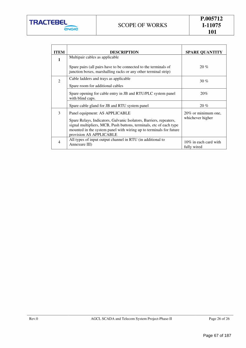
SCOPE OF WORKS
P.005712
I-11075
101
Rev.0 AGCL SCADA and Telecom System Project-Phase-II Page 26 of 26
ITEM DESCRIPTION SPARE QUANTITY
1 Multipair cables as applicable
Spare pairs (all pairs have to be connected to the terminals of
junction boxes, marshalling racks or any other terminal strip)
20 %
2 Cable ladders and trays as applicable
Spare room for additional cables
30 %
Spare opening for cable entry in JB and RTU/PLC system panel
with blind caps.
20%
Spare cable gland for JB and RTU system panel 20 %
3 Panel equipment: AS APPLICABLE
Spare Relays, Indicators, Galvanic Isolators, Barriers, repeaters,
signal multipliers, MCB, Push buttons, terminals, etc of each type
mounted in the system panel with wiring up to terminals for future
provision AS APPLICABLE
20% or minimum one,
whichever higher
4 All types of input output channel in RTU (in additional to
Annexure III) 10% in each card with
fully wired
Page 67 of 187
PTS-INSTRUMENTATION & CONTROL SYSTEM
P.005712
I-11097
101
ASSAM GAS COMPANY LTD
SCADA AND TELECOM SYSTEM FOR AGCL GAS PIPELINE
NETWORK - PAHSE-II
TRACTEBEL ENGINEERING PVT. LTD.
PARTCULAR TECHNICAL SPECIFICATION
INSTRUMENTATION & CONTROL SYSTEM
RERT
DOC. NO. P.005712 -I-11097-101
0 23.01.2019 Release for Procurement MA SHD SK
Rev. Date Subject of revision Prepared By Checked By Approved By
Page 68 of 187
PTS-INSTRUMENTATION & CONTROL SYSTEM
P.005712
I-11097
101
Rev.0 AGCL SCADA and Telecom System Project-Phase-II Page I of I
TABLE OF CONTENTS
1.0 SCOPE .................................................................................................................................... 1
2.0 INSTRUMENTS SPECIFICATION ............................................................................................ 1
3.0 INSTRUMENTATION CABLES ................................................................................................. 2
4.0 FLOW CONTROL VALVE ......................................................................................................... 5
5.0 FLOW COMPUTER .................................................................................................................. 6
Σ Σ Σ
Page 69 of 187
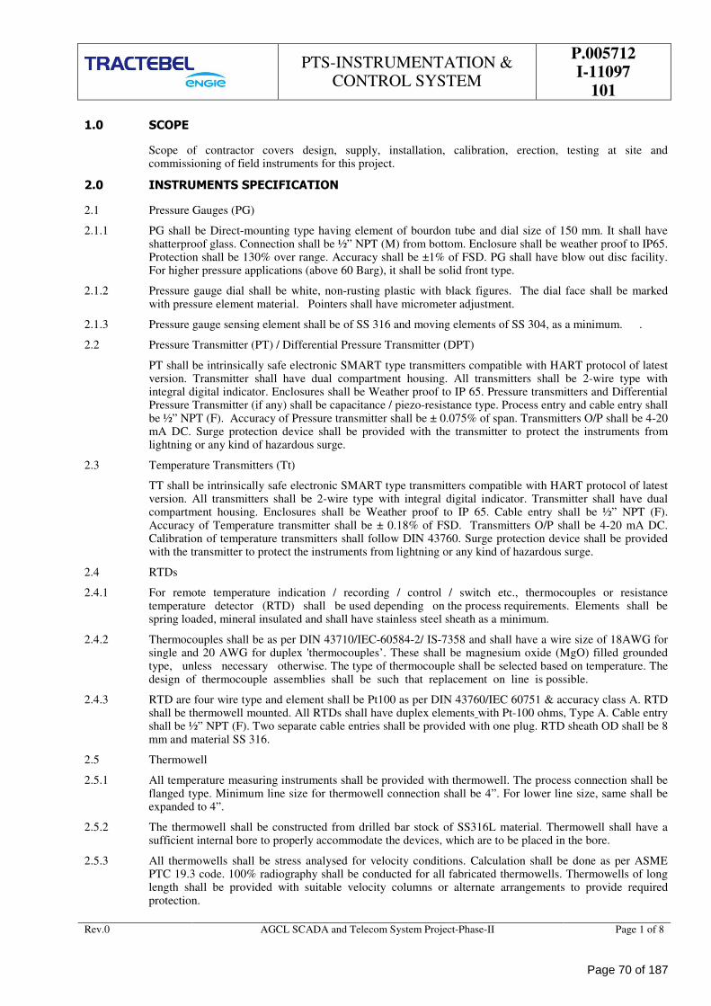
PTS-INSTRUMENTATION & CONTROL SYSTEM
P.005712
I-11097
101
Rev.0 AGCL SCADA and Telecom System Project-Phase-II Page 1 of 8
1.0 SCOPE
Scope of contractor covers design, supply, installation, calibration, erection, testing at site and commissioning of field instruments for this project.
2.0 INSTRUMENTS SPECIFICATION
2.1 Pressure Gauges (PG)
2.1.1 PG shall be Direct-mounting type having element of bourdon tube and dial size of 150 mm. It shall have shatterproof glass. Connection shall be ½” NPT (M) from bottom. Enclosure shall be weather proof to IP65. Protection shall be 130% over range. Accuracy shall be ±1% of FSD. PG shall have blow out disc facility. For higher pressure applications (above 60 Barg), it shall be solid front type.
2.1.2 Pressure gauge dial shall be white, non-rusting plastic with black figures. The dial face shall be marked with pressure element material. Pointers shall have micrometer adjustment.
2.1.3 Pressure gauge sensing element shall be of SS 316 and moving elements of SS 304, as a minimum. .
2.2 Pressure Transmitter (PT) / Differential Pressure Transmitter (DPT)
PT shall be intrinsically safe electronic SMART type transmitters compatible with HART protocol of latest version. Transmitter shall have dual compartment housing. All transmitters shall be 2-wire type with integral digital indicator. Enclosures shall be Weather proof to IP 65. Pressure transmitters and Differential Pressure Transmitter (if any) shall be capacitance / piezo-resistance type. Process entry and cable entry shall be ½” NPT (F). Accuracy of Pressure transmitter shall be ± 0.075% of span. Transmitters O/P shall be 4-20 mA DC. Surge protection device shall be provided with the transmitter to protect the instruments from lightning or any kind of hazardous surge.
2.3 Temperature Transmitters (Tt)
TT shall be intrinsically safe electronic SMART type transmitters compatible with HART protocol of latest version. All transmitters shall be 2-wire type with integral digital indicator. Transmitter shall have dual compartment housing. Enclosures shall be Weather proof to IP 65. Cable entry shall be ½” NPT (F). Accuracy of Temperature transmitter shall be ± 0.18% of FSD. Transmitters O/P shall be 4-20 mA DC. Calibration of temperature transmitters shall follow DIN 43760. Surge protection device shall be provided with the transmitter to protect the instruments from lightning or any kind of hazardous surge.
2.4 RTDs
2.4.1 For remote temperature indication / recording / control / switch etc., thermocouples or resistance temperature detector (RTD) shall be used depending on the process requirements. Elements shall be spring loaded, mineral insulated and shall have stainless steel sheath as a minimum.
2.4.2 Thermocouples shall be as per DIN 43710/IEC-60584-2/ IS-7358 and shall have a wire size of 18AWG for single and 20 AWG for duplex 'thermocouples’. These shall be magnesium oxide (MgO) filled grounded type, unless necessary otherwise. The type of thermocouple shall be selected based on temperature. The design of thermocouple assemblies shall be such that replacement on line is possible.
2.4.3 RTD are four wire type and element shall be Pt100 as per DIN 43760/IEC 60751 & accuracy class A. RTD shall be thermowell mounted. All RTDs shall have duplex elements with Pt-100 ohms, Type A. Cable entry shall be ½” NPT (F). Two separate cable entries shall be provided with one plug. RTD sheath OD shall be 8 mm and material SS 316.
2.5 Thermowell
2.5.1 All temperature measuring instruments shall be provided with thermowell. The process connection shall be flanged type. Minimum line size for thermowell connection shall be 4”. For lower line size, same shall be expanded to 4”.
2.5.2 The thermowell shall be constructed from drilled bar stock of SS316L material. Thermowell shall have a sufficient internal bore to properly accommodate the devices, which are to be placed in the bore.
2.5.3 All thermowells shall be stress analysed for velocity conditions. Calculation shall be done as per ASME PTC 19.3 code. 100% radiography shall be conducted for all fabricated thermowells. Thermowells of long length shall be provided with suitable velocity columns or alternate arrangements to provide required protection.
Page 70 of 187
PTS-INSTRUMENTATION & CONTROL SYSTEM
P.005712
I-11097
101
Rev.0 AGCL SCADA and Telecom System Project-Phase-II Page 2 of 8
2.5.4 Immersion length of thermowell shall be a follows
Line size Immersion length
From 4” to 6” 280mm
From 8” onward 320mm
Vessel/ Column 400mm
3.0 INSTRUMENTATION CABLES
3.1 Design & Construction
All cables shall be FRLS type.
1P x1.5 mm², 2P x1.5 mm², 6P x 0.5 mm², 12P x 0.5 mm², 1Q x 1.5 mm² and 3 C x 2.5mm² , 1Cx 6mm2 power cable shall be used for instrumentation purposes. No other combination shall be acceptable. Contractor to also note that all multipair cables shall have 20% spare pairs which may be used in future. These spare pairs shall be terminated in junction box.
Separate multipair cables shall be used for analog input, analog output, digital input & digital output signal. No signal mixing shall be permitted.
Triad or Quad cable shall be used for temperature element to temperature transmitter. Vendor shall consider the length as required.
3.2 Single Pair & Triad Shielded Cable
3.2.1 Each core shall be 1.5 mm2 made of 7 stranded annealed electrolytic copper conductor. Each strand shall be 0.53 mm dia.
3.2.2 For Intrinsically safe application, primary insulation shall be low density poly ethylene (LDPE). For non-intrinsically safe application, primary insulation shall be 85 °C poly-vinyle chloride (PVC) as per IS5831 Type C. Thickness shall be 0.5 mm minimum.
3.2.3 A pair shall have twisted cores and number of twists shall be not less than 10 per metre. Colour of core insulation shall be black blue in pair and black, blue and brown in triad.
3.2.4 Individual pair shall be shielded. Shield shall be Aluminium backed by mylar / polyester tape with the metallic side down helically applied with either side 25% overlap and 100% coverage. Minimum shield thickness shall be 0.05 mm. Drain wire shall be 0.5 mm2 multi-strand bare tinned annealed copper conductor. The drain wire shall be in continuous contact with Aluminium side of the shield.
3.2.5 Inner and outer jacket shall be made of extruded flame retardant 90oC PVC to IS 5831-Type ST2. Oxygen index of PVC shall be over 30%. Temperature Index shall be over 250oC. The thickness of the jacket shall be as per IS-1554 Part 1.
3.2.6 Inner jacket colour shall be black. Outer jacket colour shall be black except, for cables to be used in intrinsically safe systems, where it shall be light blue. A rip cord shall be provided for inner jacket.
3.2.7 Armour over inner jacket shall be galvanized steel wire as per IS-1554 Part 1.
3.3 Multipair Cable With Individual Pair And Overall Shield
3.3.1 Generally the cable shall be same as single pair shielded cable except conductor sizes shall be 0.5 mm2 made of 7 strands of annealed electrolytic copper conductor. Each strand shall be of 0.30 mm dia.
3.3.2 Overall shield shall be of Aluminium backed up by mylar / polyester tape helically applied with the metallic side down with either side 25% overlap and 100% coverage. Minimum shield thickness shall be 0.075 mm. Drain wire shall be similar to individual pair drain wire and shall be of the overall shield.
3.3.3 A pair of communication wire shall be provided for multi-pair cables. Each wire shall be 0.5 mm2 of plain annealed single or multi-strand copper conductor with 0.4 mm thick 85 °C PVC insulation. Insulation shall be green and red colour coded.
3.3.4 Pair identification shall be with numbers at interval of not more than 250 mm as per vendor’s standard.
3.3.5 Multipair cable with only Overall Shield
3.3.6 These cables shall be same as described in Section 4.2 except that the individual pair shall not have
Page 71 of 187
PTS-INSTRUMENTATION & CONTROL SYSTEM
P.005712
I-11097
101
Rev.0 AGCL SCADA and Telecom System Project-Phase-II Page 3 of 8
shielding.
3.4 Control Cable
3.4.1 Single pair control cables shall be used between field mounted solenoid valves and junction boxes/local control panels.
3.4.2 Multi pair control cables shall be used between junction boxes/local control panel and control room mounted devices in general. These cables shall have only overall shielding.
3.4.3 These control cables shall have 1.5 sq mm conductor size with 7 stranded conductors of annealed electrolytic grade copper, with each strand of 0.53 mm diameter.
3.5 Thermocouple Extension Cables
3.5.1 Single pair shielded thermocouple extension cables shall be used between thermocouple head and junction boxes transmitters/local control panel mounted instruments.
3.5.2 Multi pair, individually and overall shielded thermocouple extension cables shall be used between junction boxes and control room mounted devices.
3.5.3 The type of thermocouple extension cables shall be compatible with thermocouple used. In addition the colour coding of the primary insulation shall be as per ANSI MC 96.1.
3.5.4 The cable shall have 16 AWG and 20AWG solid conductors for single and multipairs respectively.
3.5.5 Shield shall be aluminium backed by mylar/polyester tape bonded together, helically applied with the metallic side down with either side having 25% overlap and 100% coverage. The minimum shield thickness shall be 0.05 mm in case of single pair/ traid and 0.075 mm incase of multipair/triad cable surface. Minimum shield thickness shall be 0.05 mm for single pair and 0.075 mm for multipair cable. Drain wire shall be 0.5 mm2 multistrand bare tinned annealed copper conductor. The drain wire shall be in continuous contact with the aluminium side of the shield.
3.5.6 Inductance shall not exceed 4mH/Km. However for J-type thermocouple inductance could be 8 mH/km.
3.5.7 All multi-pair cables shall have preferably 6 pairs/12 pairs/20 pairs.
3.6 Power Supply and Other Cables
3.6.1 All power supply cables shall be as per IS-1554 Part I and shall have copper /aluminium conductors depending on conductor size.
3.6.2 Power cables shall be 3-core, minimum 2.5 mm2 copper conductors with PVC insulation, galvanized steel armoring and overall PVC sheathing.
3.7 CABLE GLANDS
3.7.1 Cable gland shall be provided for all the above mentioned cables both at field instrument, junction boxes side, RTU/PLC and at control room side.
3.7.2 All cables glands shall be of nickel-plated brass WP and they shall be double compression type suitable for armoured cables.
3.7.3 Contractor shall provide insulating glands wherever applicable to protect the CP current drainage.
3.7.4 Flame proof glands at RTU end and wherever required shall be supplied with Ex (d) certification.
3.8 CABLE TRAYS AND CABLE DUCTS
3.8.1 All branch cables/tubes shall run on cable trays.
3.8.2 These cable trays shall be made out of galvanized iron-perforated type of 2.5 mm thickness. 50 mm x 50 mm angle shall be used as a minimum.
3.8.3 Suitable cable clamps shall be supplied for binding the cables/tubes at every 500 mm. Instrument Support/Structural Steel.
3.8.4 Maximum width of the cable tray shall be 600mm and height 50mm, 75mm or 100mm as applicable. 25% spare capacity shall be provided for cable trays.
3.9 Electrical Characteristics
Page 72 of 187
PTS-INSTRUMENTATION & CONTROL SYSTEM
P.005712
I-11097
101
Rev.0 AGCL SCADA and Telecom System Project-Phase-II Page 4 of 8
3.9.1 Resistance:
3.9.2 Maximum DC resistance of the conductor of the completed cable shall not exceed 12.3 Ω / km at 20oC for cables with 1.5 mm2 conductors and 39.7 Ω / km at 20oC for cables with 0.5 mm2 conductors.
3.9.3 Mutual Capacitance:
3.9.4 The mutual capacitance of the pairs or adjacent cores shall not exceed a maximum of 250 pF / m at a frequency of 1 kHz.
3.9.5 Capacitance between any core or screen:
3.9.6 The capacitance between any core or screen shall not exceed a maximum of 400 pF / m at a frequency of 1 kHz.
3.9.7 L/R ratio of adjacent core shall not exceed 40 µH / Ω for cables with 1.5 mm2 conductors and 25 µH / Ω for cables with 0.5 mm2 conductors.
3.9.8 The drain wire resistance including shield shall not exceed 30 Ω / km.
3.9.9 Electrostatic noise rejection ratio shall be over 76 dB.
3.10 Inspection And Testing
Owner reserves the right to test and inspect all the items at the manufacture’s works.
Manufacturer shall furnish documents such as test certificates to prove the quality and composition of the materials used for manufacturing the cable to the satisfaction of Owner/Owner’s Representative during expediting and inspection.
TYPE TEST:
a) Type Certificates shall be furnished.
b) Cable shall be flame retardant to IEC 332-3 Part 3 Cat A.
ROUTINE TESTS:
a) These tests shall be carried out by manufacturer during various stages of manufacturing. Owner shall review the related documents.
a) Insulation and Sheaths : All tests as per IS-5831 except insulation resistance, voltage and spark test shall be as per BS-5308 Part 2.
b) Armour test as per IS-3975.
d) Conductor resistance.
e) Cable capacitance, L/R ratio.
ACCEPTANCE TEST:
These tests shall be carried out in the presence of Owner / Owner’s Representative.
Continuity test:
a) Voltage test as per BS-5308 Part 2.
b) Conductor resistance and drain wire resistance.
c) Cable capacitance and L/R ratio test.
d) Electrostatic noise rejection test, type wise for each lot.
e) Tests for uniformity of galvanization of armour as per IS-2633.
f) Oxygen index test as per ASTM D 2863, temp. index test, smoke density rating test, acid gas generation test and flammability test.
g) Dimensional check for overall diameter and under armour/over armour diameter.
h) Overall finish check. In case of any lump purchaser will have the right to cut outer sheath for lump portion and reject the cable.
Page 73 of 187
PTS-INSTRUMENTATION & CONTROL SYSTEM
P.005712
I-11097
101
Rev.0 AGCL SCADA and Telecom System Project-Phase-II Page 5 of 8
i) Check of Drum length and overall length tolerances.
Immediately after completion of electrical tests, the ends of the cable shall be sealed to prevent ingress of moisture with suitable PVC/Rubber caps.
4.0 FLOW CONTROL VALVE
4.1 Valve Selection & Construction
Control valves shall be globe type single seated with top guided trim which can be removed from the top of the valve. However, selection of control valve shall be based upon station capacity and trim as required to satisfy the expected flow rate range as specified elsewhere in the tender document. All possible effect of erosion, cavitations and noise shall be considered during valve selection. Maximum permissible noise level shall be 85dBA at 1 m from the valve in all directions. Minimum flow shall take place at 15% travel position to prevent erosion of valve trim.
Equal percentage and linear trim characteristic shall be used as applicable to process requirement. Quick opening trim may be used for ON/OFF service only.
Globe valves are preferred for general service ,Single seated with heavy top guided, double seated with top and bottom guided, and shall be cage guided except in dirty or abrasive services (Produced liquids) where post guiding is preferred.
Cage type and single seated globe body valves shall be having process Fluid tending to open the valve.
Shut-off leakage of valves shall be in accordance with ANSIB16.104/FCI 70.2. Generally shutoff shall be class IV or better.
Body rating, flange rating and facing shall be in accordance with the piping class specification for the associated piping.
Valve packing boxes shall be flange bolted to the bonnet. Valve packing shall be spring loaded and adjustable. Teflon V rings/ PTFE shall be used up to 212oC. Above this temperature graphite/grafoil shall be used with an external lubricator and isolation valve.
Material used for trim shall be minimum SS316, with guide bushing of hardened stainless steel like 17-4PH.
Pneumatic connections shall be 1/4" NPTF as minimum. Larger Port sizes shall be used wherever required for larger sizes of actuators.
Termination in wiring enclosures shall be via fixed terminals. Flying leads shall not be used.
Flow direction shall be stamped or cast on the body of all valves.
4.2 Control Valve Sizing
Control valves shall be sized for normal / minimum flow at about 75-15% valve opening. At Maximum flow, valve opening of 85% may be considered.
The contractor shall submit Control Valve sizing calculation performed in accordance with ISA S 75.01 and based on Process data.
4.3 Actuator
Control valve actuators shall be pneumatic, spring return and diaphragm or piston type. Spring shall be corrosion resistant, cadmium plated or equivalent material. Piston type actuator shall be used where diaphragm actuator cannot be used due to capacity limitation.
Actuators shall be sized for operation under maximum shutoff pressure.
Actuators shall be selected to achieve specified valve failure positions. All accessories, including pilot valves, relays, volume bottles etc. for double acting actuator or air block relays for fail in position valves, shall be supplied with the valve. A valve stem position indicator shall be provided. All control valve scales shall be calibrated from 0-100 %. Detachable side mounted heavy-duty hand wheels shall be provided for control valves wherever specified. Actuator action shall be field reversible. Diaphragm actuators shall be multiple bolted, pressed steel with Nylon reinforced Neoprene or Buna N Rubber Diaphragm. Actuators for control valves shall be pneumatic, spring-loaded diaphragm type.
4.4 Smart Positioner
Page 74 of 187
PTS-INSTRUMENTATION & CONTROL SYSTEM
P.005712
I-11097
101
Rev.0 AGCL SCADA and Telecom System Project-Phase-II Page 6 of 8
Control valve shall be supplied fitted with smart positioner. The Valve positioner shall be weather proof, rust free and intrinsically safe "smart" type with integral I/P converter and shall be of direct acting, with field reversible action. SMART I/P converters / positioners shall be provided for control valves. They shall be supplied complete with air set with input & output gauges. Gauges shall be fitted to indicate both input & output pressure.
4.5 Material
Control valve bodies shall be cast or forged carbon steel to ASTM with 316 SS trim as a minimum, however more demanding services may require other materials as specified in the applicable piping specification/Material selection chart. Satellite hardened trims shall be specified for flashing services and for critical, high pressure drops or erosive conditions.
Consideration shall be given in selection of all other valve part materials for corrosion due to process fluid and ambient conditions.
Tubing shall be seamless 316 SS tube with 316 SS double ferrule compression fittings.
4.6 Valve Name Plate
Each valve shall have SS name plate permanently fastened to the super structure which shall be visible when the valve is in service and fully insulated. The name plate shall contain the following information:
• Manufacturer's name and trade mark.
• Valve Tag no., model no. & serial no.
• Actuator model no. & serial no.
• Valve body / bore size and pressure rating.
• Failure position.
4.7 Inspection
All valves shall be tested as per API 6D, BS 6755 as mentioned in the ITP. Purchaser or their representative (s) reserve (s) the right to witness the tests.
Actuator shall be mounted on the valve and tested as follows:
To ensure smoothness of operation vendor shall perform at least five (5) Cycle (open and shut) for each valve with its actuator.
Shut valve and apply hydraulic differential pressure as given in the data sheet, across the valve. This shall be repeated at least 3 times and shutdown time noted at minimum supply pressure.
Test shall be witnessed by Purchaser or their representatives.
Final testing and approval made by Purchaser's representative shall not relieve the contractor from his responsibilities as per contract obligations.
4.8 Packing And Shipping
Valves shall be dried, greased, devoid of test media and provided with unused dry packing before dispatch. All exposed parts of the valve not made of stainless steel and other corrosion resistant material shall be coated as per relevant painting specification.
Valves shall be suitably protected against damage while in transit.
All threaded and flanged openings shall be suitably protected to prevent entry of foreign material during shipment.
Valves shall be supplied as a whole, complete with all accessories and properly packed.
5.0 FLOW COMPUTER
5.1 FC shall be compatible to all type of flow meters as per AGA standards
5.2 The flow computers shall be microprocessor based, with data entry keypad and alphanumeric display with (Backlit LED which can be seen in the dark) AGA firmware for natural gas flow measurement. Flow computer electronics shall be protected from industrial interferences; and shall be shock and vibration proof. Mounting shall be Flush panel type.
Page 75 of 187
PTS-INSTRUMENTATION & CONTROL SYSTEM
P.005712
I-11097
101
Rev.0 AGCL SCADA and Telecom System Project-Phase-II Page 7 of 8
5.3 The flow computer shall be certified for custody transfer applications by laboratory / institutes authorized by weights and measures authority of its country of origin such as NMI, PTB, Pigsar or other reputed International Standard laboratories such as Trans Canada Calibrations, (TCC) Canada, Measurement Canada, Colorado Engineering Experiment Station Inc (CEESI) USA.
5.4 The flow computer shall access the flow meter data and diagnostic data through the dedicated RS 485 or 4-20 mA or pulse provision. Flow computer shall be capable to accommodate all analogue and digital signals from the metering and filtration skids if any.
5.5 Vendor shall make provision of serial link communication ports with GC and RTU in flow computer. Vendor shall provide serial links cables and connectors at both ends. Flow computer shall also be compatible with GSM modem. However, in build GSM modem in the flow Computer are preferred.
5.6 Vendor shall note that wherever gas chromatograph is not available, the natural gas parameters shall be entered manually and FC shall perform the calculation as per standard method. In case GC is available, Flow computer shall be interfaced with Gas chromatograph for feeding online gas composition to flow computer through a modbus serial link. Vendor shall be responsible for proper integration of flow computer with gas chromatograph. Vendor shall provide all necessary hardware, software etc. in vendor’s supplied systems and other details required for interfacing of Flow computers. The flow computer shall calculate the Gross Energy, Net energy, Gross heating value and the Net Heating value of the flowing gas based on the GC data as per GPA 2145 and GPA2172 and ISO6976 (User configurable).
5.7 Flow computers shall be interfaced with RTU or directly to SCADA system through GSM modem to get gas temperature , pressure, energy flow rate and total energy, corrected & un-corrected volumetric flow rate , total flow, last day’s cumulative energy and volume, current day’s running volumetric total and energy total, volume and energy integrated at 6 a.m., gas composition ( mole%C1, C2, C3, iC4, nC4, iC5, nC5, C6+, N2, CO2, Specific gravity, Gross and Net Calorific value) etc. Contractor to note that SCADA vendors shall provide RS 232 serial link at the RTUs for interfacing of intelligent electronic devices like flow computers. For flow computer interface to RTU, vendor shall accordingly provide RS 232 link (Modicon Modbus ASCII & RTU protocol supporting IEEE single precision floating point no. with user configurable register). The digital and analog data shall be made available to RTU (SCADA) and it shall be mapped in the contiguous registers so that data can be fetched/written in minimum transactions. Provision shall also be kept at flow computer for writing data from RTU/ SCADA like gas compositions, calorific value etc. from RTU to any other remote flow computer.
5.8 From the keyboard it shall be possible to enter Specific gravity, Pressure and temperature base conditions, Atmospheric pressure as per site condition, Mol % or composition of the gas to be metered, Report headings, frequency and timing of reports, Selection of parameter to be displayed and on-demand printing of reports, Calorific value (GCV, NCV), Pressure, temperature and Specific gravity values and give compensated flow for any external conditions, Linearization of error curve & change of K-factor, Other standard features available. The flow computer shall have provision to enter default values of all inputs (inclusive of gas chromatograph) except flow, low/high alarms for all inputs (inclusive of gas chromatograph) and shall be user configurable. The flow computer shall use the default values in case any input goes beyond low/high limit.
5.9 For field verification, online speed of sound comparison between the measured speed of sound from the ultrasonic meter versus, calculated speed of sound (as per AGA10) using the on-line Gas chromatograph data shall be made available in the flow computer. The comparison shall be made in the flow computer in audit trail environment.
5.10 The stream flow computer, will compute and display the instantaneous and totalised flow rate corrected for pressure and temperature variations. The flow computer shall be microprocessor based, with keypad and alphanumeric display with AGA8 firmware for natural gas flow measurement. The flow computer shall be linked to the SCADA for providing the flow measurements of the individual stream runs and related process variables (future).
5.11 The flow computers shall have an audit trail facility. It should be able to store data for 30 days.
5.12 The standards shall be AGA-8 detailed characterization method to determine density, compressibility, super compressibility factor etc. for flow computers, AGA Report 5/GPA 2145-GPA2172/ISO6976 for energy rate and integrated energy, AGA report for flow rate and total flow for all tags for Ultrasonic meter.
5.13 The Flow computer should reject the GC data during GC calibration / Cal. Check and should use the previous data for calculation.
5.14 Alarm should appear when USM Signal strength is less than predefined limit.
Page 76 of 187
PTS-INSTRUMENTATION & CONTROL SYSTEM
P.005712
I-11097
101
Rev.0 AGCL SCADA and Telecom System Project-Phase-II Page 8 of 8
5.15 The interval between flow computer readings of Process variables shall not exceed 1 sec. Algorithm and rounding off error for computation shall be within ±0.001% of computed value. The interval between each cycle for computation of instantaneous flow rate and totalized flow shall be less than 1 sec.
5.16 The access to flow computer shall be password protected. (3-Level password protection should be a standard feature in Flow computer).
5.17 The flow computer shall have the capability to display the parameters like: Uncompensated volume flow rate, Compensated volume flow rate, Integrated volume (corrected and not corrected), Mass flow rate, Integrated mass, Density/Specific gravity, Pressure, Temperature, Energy rate & total energy, Complete gas composition, Calculated parameters (compressibility factor etc.), Current accumulation, previous day accumulation, Data entry, Error codes, Selected parameter codes, Alarms (process and systems) including diagnostic message, Engg. Units as per selected parameter, other standard displays available, and Custody transfer flow computers shall have audit trail facility. All the above data shall also be made available by vendor in the serial links to RTU.FC also cable to display others integrated skid data like filtration skid.
5.18 The software for Configuration of flow computer, Audit trail and history retrieval from flow computer shall be supplied by bidder. Supplier to provide one licensed Software in the name of Client for authenticating the algorithm written in the Flow Computers as per AGA-3/7/ 9 (as applicable).
5.19 Computational capability:
• Volume flow rate at standard, normal or operator specified base conditions (Sm3/hr). Initially configured at Base pressure: 1.01325 bara, Base temp: 15.556 degree C)
• PID algorithm for Flow control.
• Integrated corrected volume in SCM
• Energy flow rate and integrated energy (user configurable in MCal / KCal, MJ & BTU).
• Heating value calculation as per ISO-6976/GPA2145/GPA2172 (User configurable). Initially configured as per GPA 2145 or GPA 2172 (user configurable).
• Linearization of error flow curve.
• Generation of standard and user defined reports at printer. All reports shall be user configurable.
• Calculation of compressibility factor as per AGA-8 detail method / AGA-8 Gross1/ Gross2 method (user selectable).
• Previous day’s flow / energy (i.e. yesterday’s Base time total volume / energy to today’s Base time total volume / energy) & current running total for the day (i.e. volume tantalizer/ integrator value at Base time from first day) to be stored in a separate location (register) and base time shall be user configurable.
• Today’s accumulated flow /energy (running total since Base time to current time) and base time shall be user configurable.
• Generation of reports for totalised volume & energy at daily, weekly, fortnightly & monthly intervals, flow rate, pressure, temperature, Uncorrected Flow/DP, compressibility factor, alarms etc. shall be user configurable.
• Speed of Sound comparison should be done in the stream flow computer for the speed of sound measured value from the USM and the speed of sound calculation based on the GC component data as per AGA 10. If the difference between the SOS between the actual and the calculated one is more than the permissible limit then the flow computer shall generate an alarm. Also licensed software for SOS calculation shall be separately supplied by the bidder.
Σ Σ Σ
Page 77 of 187
PTS – REMOTE TERMINAL
UNIT
P.005712
I-11097
102
ASSAM GAS COMPANY LTD
SCADA AND TELECOM SYSTEM FOR AGCL GAS PIPELINE
NETWORK - PAHSE-II
TRACTEBEL ENGINEERING PVT. LTD.
PARTCULAR TECHNICAL SPECIFICATION
REMOTE TERMINAL UNIT
DOC. NO. P.005712-I-11097-102
0 23.01.2019 Release for Procurement MA SHD SK
Rev. Date Subject of revision Prepared By Checked By Approved By
Page 78 of 187
PTS – REMOTE TERMINAL
UNIT
P.005712
I-11097
102
Rev. 0 AGCL SCADA and Telecom System Project-Phase-II Page 1 of I
TABLE OF CONTENTS
1.0 SCOPE...................................................................................................................................... 1
2.0 RTU SYSTEM ............................................................................................................................ 1
3.0 RTU SPECIFICATIONS ............................................................................................................. 1
4.0 INSTALLATION & COMMISSIONING....................................................................................... 6
5.0 EQUIPMENT INSPECTION & TESTING .................................................................................... 7
6.0 TRAINING ............................................................................................................................. 10
Page 79 of 187
PTS – REMOTE TERMINAL
UNIT
P.005712
I-11097
102
Rev. 0 AGCL SCADA and Telecom System Project-Phase-II Page 1 of 10
1.0 SCOPE
This specification covers design, manufacturing, testing, supply, installation, calibration, erection, testing at
site FAT, SAT and commissioning, guarantee run, handing over of RTU.
2.0 RTU SYSTEM
2.1 RTU shall be located at each tea factory/ small industries. The system shall be rugged in construction and
suitable for working in hazardous area. RTU shall be designed by considering required Inputs & outputs and
future expansion. All the inputs & outputs including spares shall be fully wired upto the terminal blocks.
2.2 RTU shall be interfaced with telecommunication system for transferring data to Master control stations.
Telecom system shall be GSM/GPRS type. GSM Modem may be inbuilt/ integrated with RTU or separate
modem linked with RTU.
2.3 RTU shall be comprised of CPU, Power supply card, communication cards, input cards, output cards,
controller card, interface cards, wall mounted flame proof cabinet, UPS with battery and required internal
accessories.
2.4 It is the prime responsibility of Contractor to establish the communications between RTU, Telecom and
SCADA. If any additional items are required to make the system fully functional during interfacing stage,
that shall be made available to client by vendor without any price implication even though it was not
considered during bid submission.
2.5 All the supplied hardware shall be manufactured as per good engineering practices.
2.6 The bidder shall submit the drawings and documents of the complete system as indicated in MR. Bidder
shall also required to submit as built documentation, drawings of the complete system. All the submission
shall be made in hard copies and in CDs
2.7 The bidder is required to carry out civil works associated with the installation of supplied equipments at
various stations.
2.8 The bidder is required to carry out electrical works associated with the installation and commissioning of
the equipments, earthing of equipments at all sites, powering of equipments at all sites, termination of
cables as required.
2.9 RTU shall be capable of updating process parameters data and configuration data in its own built-in
memory. Time stamping of all field values shall be required at RTU. In the event of failure or break of
communication link, the RTU shall continue to scan all parameters and update its database.
2.10 RTU shall retain in its database the complete analog & digital information of the field until it completely
and correctly read by SCADA Station in order to take care of no loss of data in case of failure of stations.
The memory buffer is to be sized (by considering min 15 days down time of SCADA system or
communication between RTU and SCADA) to store all the changing data (i.e. exception report for the data
every poll time). SCADA system shall receive the same without any loss of data after resuming the
communication.
3.0 RTU SPECIFICATIONS
RTU shall be rugged in construction, capability to implement control logics, close loop controls, interlocks
& functionality as specified in tender specification and suitable for working in hazardous area & open
environment conditions.
3.1 General
This shall be microprocessor based programmable units with both erasable ROM and RAM memory.
Control device shall have its own processor, memory, power supply unit & communication processors and
I/O cards complete in all respects. All RTU shall be modular and rack/din rail mounted. The complete
system shall be supplied with all its components including the cabinets.
3.1.1 The I/O cards shall not be combined for the functionalities i.e. each card shall perform dedicated
functionality w.r.t analog input, analog output, digital input, digital output. Mix configurable type input
output cards are not acceptable.
Page 80 of 187
PTS – REMOTE TERMINAL
UNIT
P.005712
I-11097
102
Rev. 0 AGCL SCADA and Telecom System Project-Phase-II Page 2 of 10
3.1.2 The entire supplied RTU shall be with same make & model no., differing only in number of I/O cards.
3.1.3 RTU Subsystems
The RTUs shall comprise the following subsystems:
• Central processor with system software.
• Analogue input
• Contact (digital) input
• Analogue output
• Contact (digital) output
• Communications card (RS232/RS485)
• Ethernet port.
• SMPS Power supply
• Diagnostic tools
3.2 RTU software
• Programming software as per IEC 61131
• Local and remote Diagnostic tool
3.3 Digital inputs
Typical specification of Digital Input Modules is as given below:
Input Type : Max 16 Volt free contacts (2 wire isolated)
Contact Wetting : 2-4mA per input at 24V DC
Resistance recognized : Not exceeding 1 Kilo Ohms as a closed contact
Resistance recognized : Not less than 50 Kilo Ohms as an open contact
Isolation : Using optocouplers or vendor specific.
Insulation resistance : 20M ohms at 500V DC inputs
Debounce circuitry : 10 m/sec
Voltage withstand : 1.5 KV RMS Capability
3.4 DIGITAL OUTPUTS
Typical specification of Digital Output Modules is as given below:
Output Type : Max. 16 relay contacts
Relay Type : Miniature power relay
Contact arrangement : 1 NO + 1 NC relay contacts configuration to be provided up to the
RTU terminal block
Contact Rating : Potential free contact rating of output interposing relay for each DO
point
(Contact rating 48 V DC, 2A; 230V AC, 5A)
(Vendor to provide interposing relays for each digital output point)
Isolation : 2KV RMS Contacts to Logic
DO command activation : Configurable Pulse duration
Page 81 of 187
PTS – REMOTE TERMINAL
UNIT
P.005712
I-11097
102
Rev. 0 AGCL SCADA and Telecom System Project-Phase-II Page 3 of 10
Security : Output contacts shall be monitored via opto-isolators, shall be short
circuit proof and protected by suitable mechanism like fuse with
suitable visual fuse blown indication provided.
3.5 Analog inputs
Typical specification of Analog Input Modules is as given below:
Input Type : Max 8 isolated, Current Inputs
Ranges : 4 - 20 mA
Multiplexer : Vendor standard
ADC Type : 12 bit binary (exclusive of sign bit)
Series Mode rejection : Greater than 30 db at 50 Hz
Common Mode rejection : Greater than 100 db at 50 Hz
Roll over error : 1 bit
Temperature : 0.005% per degree C
Coefficient
Accuracy : ± 0.1% of range including drop in resistor
3.6 Analog outputs
Typical Specification of Analog Output Modules is as given below:
Output type : Max. 8 Completely Isolated current (4-20 mA) outputs.
DAC Type : 12 bit binary (exclusive of sign bit)
DAC Span : 10V or 5V
Output Range : 4-20 mA DC
Isolation : Each output shall be isolated from logic and the others to 500 Volts
Loading : 1K ohm for Current outputs
Differential Linearity : 1/2 L.S.B
Temperature coefficient : 0.01% FSD per degree C
Accuracy : ± 0.1% of range
Retentivity : Set-point value to be held by AO card till updated by new set-point
value from Master Control station
3.7 The RTU shall be configured such that failure of any part of an RTU subsystem (module) except the CPU,
power supply module shall not directly affect the integrity of the unit, as a whole.
3.8 In case of Power Failure at RTU, when power is restored, it should retain all previous configurations/ set
points.
3.9 COMMUNICATIONS
The RTU shall support both internal and external communications functions.
The communications network internal to the RTU shall be designed and implemented in such a way that the
passing of data and commands between modules shall not be prevented by the failure of any module not
directly involved in the communication exchange. In addition, the internal network shall not become
overloaded under the heaviest traffic possible in RTUs ultimate expansion configuration.
Each RTU shall recognize its own unique address. The LED indication shall be provided in the RTU to
check the health of RTU communication.
Communication channels shall be provided in RTU for communicating with GSM modem/SCADA system.
Page 82 of 187
PTS – REMOTE TERMINAL
UNIT
P.005712
I-11097
102
Rev. 0 AGCL SCADA and Telecom System Project-Phase-II Page 4 of 10
3.10 Features
3.10.1 The control device sub-system shall support the following:
a) Scanning of Input and Output
b) Fast Scanning of selected I/O points.
c) Field input initiated discrete control action
d) Discrete control action corresponding to Remote Control command reception.
e) Operator initiated discrete control action with check before execute and time out feature.
f) Operator initiated discrete control with sequencing and interlocking.
g) Derivation of calculated digital points based on logical functions AND, OR, NOT etc. from digital and
analog points.
h) Derivation of calculated analog points based on arithmetic functions +, -, /, *, sq, root etc. and driving
external hardware. Calculation shall be performed in RTU in engineering units with 16 bit floating
point accuracy, required in case engineering conversion is being done at RTU level. (Calculations shall
be performed in the SCADA host in case engineering conversion is being implemented in the SCADA
server.)
i) Derivation of counter values using Integration of hardware and software generated Analog points.
j) RTU resident accumulator points driven by analog points.
k) Remote configuration of RTU from SCADA station (MCS) through PDT (Laptop)/PC.
l) Compatible with serial communication.
3.10.2 Automatic time synchronization of Remote telemetry units shall be implemented from Stations with a
resolution of 100 msec.
3.10.3 It shall have a self-diagnostic feature and software watchdog timer devices to monitor & report the
healthiness of CPU, memory, power supply, comm. interfaces and Input/Output modules at the local level.
Further, it shall support remote diagnostics from different station so that all these status shall be transmitted
to different station and displayed in the RTU status graphic.
3.10.4 RTU shall be intelligent in support of the following:
a) It shall process the analog data for high-low limit violations as per stored limit tables and communicate
the same to SCADA station along with time stamping.
b) Linear conversion to engineering units and input filtering, in case engineering unit conversion is being
done at RTU level [conversion of raw data to normalized value (e.g. 0 to 1.0) for communication shall
also be acceptable].
c) To support remote reconfiguration and downloading of parameters i.e. addition, deletion, modification
and reassignment with different range, limits etc. from SCADA station to avoid local engineering at
RTU level. The following requirements of RTU configuration from SCADA station shall be fulfilled:
• Analog alarm limits
• Analog scaling factor for engineering unit conversion
• Threshold value
• Smoothing factor (filter time constant) etc.
• Set point feeding from remote
3.10.5 The system shall have the facility to attach to each digital event signal a time tag generated by the RTU
local clock to enable the occurrence to be recorded and transferred with a resolution of 100 ms.
3.10.6 It shall be possible to have highest priority for alarms, in order for the same to be sent to all Stations. The
Contractor has the option to implement the feature of association of the alarm priority at the RTU level or
Page 83 of 187
PTS – REMOTE TERMINAL
UNIT
P.005712
I-11097
102
Rev. 0 AGCL SCADA and Telecom System Project-Phase-II Page 5 of 10
SCADA server level.
3.10.7 RTU shall not generate any false control signal due to power supply on-off conditions.
3.10.8 RTU shall support communication protocol supporting report by exception to prevent unnecessary data
communication when the data is not changing.
3.10.9 It shall provide error detection and control feature for data communication with all Stations to ensure data
integrity.
3.10.10 It shall have feature of connecting a pluggable Programmable Diagnostic Test unit (PDT) with keyboard &
monitors diagnostic and programming aid to trouble shoot and configuration tool and I/O boards. It shall be
possible to exercise all the functions without disconnecting from process.
3.10.11 It shall have provision of applying filtering on the input signals and scaling for engg. units conversion.
3.10.12 It shall operate from power supply as indicated in the tender. Separate on/off power supply switch and fuse
shall be supplied. Adequate isolation of input, output and power supply circuits shall be provided along with
over voltage and short circuit protection.
3.10.13 The RTU shall be immune to radio frequency interference generated by any nearby source meeting the
latest international standards in this regard (MIL, VDE etc.).
3.10.14 RTU shall be on a pair of communication channels. Upon failure of primary channel, RTU shall respond to
SCADA station requests/ interrogation on secondary channel automatically without any loss of data &
operation. System shall provide status on the availability of each of the channels.
3.11 SCAN Rates
The local scan rates for individual I/O modules shall be such that the time-tagging resolution and system
performance requirements are achieved.
The consideration of scan times shall include the acquisition of data, processing and updating of the RTU
database. The overall local scan shall be defined as the time required to acquire field data and update the
RTU database and the same shall be much faster than RTU poll time by SCADA station. It is expected that
scan rate shall not exceed 100 msec.
3.12 SET-Point Controls
a) All analog output control functions shall utilize the select-check-operate control sequence associated
with set point control.
b) At the RTU, failure of a module in a subsystem shall be identified by an individual LED display.
c) Each I/O shall be protected against the reversal polarity of the power voltage to I/O.
d) All the data shall be available in the engineering units in the RTU database. The Contractor has the
option to implement the feature of engineering unit conversion at the RTU level.
3.13 Serial Link Requirement
a) RTU vender shall provide appropriate number of RS 485 & RS 232 serial ports for each RTU as per
tender requirement.
b) Contractor shall provide all the software tools and programs (source code) used to interface RTU with
different IEDs. It shall be possible for OWNER to integrate other IEDs with the RTU in future. To
achieve the same RTU shall have provision for integrating IEDs and all necessary software, compilers,
tools etc shall be supplied by the Contractor. Hence the integration of IEDs (of any protocol and not
just MODBUS) with the RTU shall be totally end-user configurable.
c) The alarms for power supply/ serial link failure/ malfunction through serial link shall be implemented.
d) The RTU memory sizing shall be adequate for required nos. (As applicable) of IED system & serially
connected with the RTU including the spare ports.
e) All RTU shall be user programmable for interfacing with any kind of IEDs like Flow Computers, flow
meter EVC, Gas Chromatographs etc.
Page 84 of 187
PTS – REMOTE TERMINAL
UNIT
P.005712
I-11097
102
Rev. 0 AGCL SCADA and Telecom System Project-Phase-II Page 6 of 10
4.0 INSTALLATION & COMMISSIONING
4.1 The installation and commissioning of all the equipments associated with SCADA and RTU system at
various sites including the activities of instrumentation signal interconnections, electrical works with power
supply distribution and grounding works and other necessary facilities and coordination/ interfacing with
various sub-contractors is the responsibility of the Contractor.
4.2 Contractor shall be responsible for proper selection of the communication cables [with suitable cable
properties, shielded cable with low capacitance (8-10 pF/foot)] for ensuring good quality communication
with telecommunications & other panels.
4.3 Contractor shall bring all installation aids, test equipments and qualified and experienced personnel, in order
to carry out the job successfully. A list of the same shall be submitted to the CLIENT/CLIENT’S
REPRESENTATIVE for review.
4.4 Contractor shall carry all the necessary tool and tackles like 4-20 mA current source, multimeter,
RS232/RS485 converters, protocol analyser and other diagnostic tools as required during testing and
commissioning.
4.5 All technical personnel assigned to the site by Contractor must be fully conversant with the specific system
and its software packages. The Contractor’s field personnel shall have both hardware and software
capability to bring the system on line quickly and efficiently and with a minimum of interference with other
concurrent construction and commissioning activity.
4.6 The commissioning spares for all the items/ equipments is included along with commissioning services as
required to commission the complete system. The consumables required during commissioning of system is
included as part of commissioning spares.
4.7 Contractor shall at his own expense supply and provide all the equipment, tools, temporary works materials
both for temporary and for permanent works, labour, supervisors, engineers and specialists, movement of
the supplied equipment at the site, required for installation, commissioning, execution and completion of the
works. The Contractor shall make his own arrangements at his own cost for the transport where necessary
of his staff and labour to and from the Site of the works.
4.8 The Contractor shall provide and maintain an office at the Site, during Installation, Testing &
Commissioning phase, for his staff, and such office shall be open at all reasonable hours to receive
instructions, notice or other communications as per the permission granted from CLIENT’S.
4.9 Appropriate storage of the materials to be supplied in this contract will be arranged at the site by the
Contractor at the various stations after the materials have been delivered by the Contractor. The Contractor
shall be responsible for the storage, security and safety of all other materials, tools etc. brought by the
Contractor for the installation and commissioning of the system at the site.
4.10 The Contractor's responsibility at site shall include all the activities necessary to be performed to complete
the entire job as per the contract requirements including the following as a minimum.
a) Receipt of hardware, software and checking the adequacy and completeness of supply.
b) Storage, safety and security of the equipments and other materials including software at site.
c) Installation of the complete system including power supply, earthing, cable terminations, calibration,
civil & electrical works. Obtaining information/ Coordination/ interfacing with various other
contractors (Electrical, Instrumentation, Telecom etc.) through CLIENT/CLIENT’S
REPRESENTATIVE.
d) Checking of equipment installation.
e) Checking of interconnection and overall system functionality.
f) Online/ offline debugging of the system.
g) Coordination/ interfacing (including obtaining relevant details) with Instrumentation contractor and
Electrical contractor through CLIENT/CLIENT’S REPRESENTATIVE.
h) Coordination/ interfacing (including obtaining relevant details) with Metering contractor through
CLIENT/CLIENT’S REPRESENTATIVE
Page 85 of 187
PTS – REMOTE TERMINAL
UNIT
P.005712
I-11097
102
Rev. 0 AGCL SCADA and Telecom System Project-Phase-II Page 7 of 10
i) On line testing and commissioning RTU system.
4.11 Contractor to note that there could be minor database changes & logic changes during site commissioning
phase as required by the CLIENT. The same to be taken care by the Contractor as part of the project
requirements.
5.0 EQUIPMENT INSPECTION & TESTING
5.1 Inspection
a) All factory tests will be witnessed by CLIENT/CLIENT’S REPRESENTATIVE.
b) CLIENT/CLIENT’S REPRESENTATIVE shall have free entry and access at all phases of the project
to all parts of Contractor's facilities associated with manufacturing and testing of system.
c) Contractor shall invite CLIENT/CLIENT’S REPRESENTATIVE well in advance with minimum 1
month notice of the date at which the system is ready for testing.
d) The equipment will not be shipped before they have been officially released in the form of release notes
by CLIENT/CLIENT’S REPRESENTATIVE.
e) Contractor shall provide CLIENT/CLIENT’S REPRESENTATIVE with all reasonable facilities
necessary to determine compliance to the system specification.
f) Contractor to note that acceptance of the equipments and the system by OWNER or exemption of
inspection & testing shall in no way absolve the Contractor of his responsibility to deliver the system
meeting all the requirements specified in the specification. Contractor shall be responsible till the
completion of the warranty, for any corrections/ modifications including supply and implementation of
hardware & software to fulfill the requirements of the contract/ up gradation including supply and
implementation of hardware & software to meet the functionality and performance of the contract.
g) Contractor personnel shall be actively involved during factory acceptance and site acceptance testing.
h) All the RTU tests as per the approved documents shall be carried out at the Contractor's works, testing
laboratory and work sites at Contractor's cost. The Contractor shall provide assistance; instruments,
labour and materials as are normally required for the examining, measuring and testing any
workmanship as may be selected and required.
i) These tests will encompass all the material and equipment delivered and software pertaining to system
including the equipment and software supplied by Contractor. Pre-FAT report duly witnessed and
cleared by Contractor shall be available for reference during FAT.
5.2 Testing
Testing of system shall consist of:
a) Pre-Factory Acceptance Test (Pre-FAT)
b) Factory Acceptance Testing (FAT)
c) Pre SAT & Site Acceptance Testing (SAT)
d) Test Run
5.2.1 Pre-FAT
Pre-FAT shall be conducted based on the approved FAT document and the same shall be duly witnessed &
cleared by the system engineering group of the Contractor.
During the Pre-FAT testing phase, the Contractor shall ensure that the RTU system performs according to
the requirements of tender, FDS & other finalised engineering documents and furnishes the written
undertaking to the CLIENT in this regard, prior to offering the system for FAT to CLIENT.
Contractor shall submit pre FAT report for our review before FAT call. Pre FAT shall be conducted as per
the approved FAT procedure and on real or project specific component with observed results. Pre FAT test
shall covers minimum aspect as specified in FAT clause. Pre FAT result shall be verified during FAT.
Page 86 of 187
PTS – REMOTE TERMINAL
UNIT
P.005712
I-11097
102
Rev. 0 AGCL SCADA and Telecom System Project-Phase-II Page 8 of 10
5.2.2 Factory acceptance testing (FAT)
The FAT document shall be prepared covering all hardware, software and system functionalities including
system expansion requirements of tender & FDS. Factory acceptance test will be done based on the
stipulations in the approved FAT document, which shall completely fulfill the contract requirements and
approved RTU FDS documents.
FAT shall be carried out in Contractor’s premises.
The system testing shall cover the following aspects as a minimum:
a) Visual and mechanical testing to ensure correct, proper, good and neat workmanship.
b) Demonstration of the complete system functionalities, hardware & software compliances wrt all the
equipments including RTUs.
c) Checking of complete database definitions for the proper system configuration.
d) Testing of system passwords and security features.
e) Checking of various log formats, reports, archiving functions.
f) Checking of system loading w.r.t CPU, memory, disk, as per the requirements.
g) Checking of system diagnostics for all the equipments as per the requirements, power failure and
system restarts.
h) Redundancy check
i) IO & Serial communication checking by simulation
j) System building procedures and verifications.
5.2.3 On line testing, Commissioning
a) Prior to SAT, Contractor shall test all the stations hardware & software such as correctness of complete
SCADA database, complete checking and testing of I/O database, testing of serial interfaces as
applicable.
b) Prior to SAT, the activities of installation, system on-line testing and commissioning shall be performed
by Contractor as per their Company standard & established practices & procedures to ensure that good
techniques and best engineering practices had been followed, while ensuring correctness &
completeness of the same.
c) Contractor shall conduct the SAT after successful integration & commissioning of the complete system
and after interfacing of all actual field signals with the system including the successful completion of
on-line testing of all the system.
5.2.4 Site Acceptance Testing (SAT)
a) The SAT document shall be prepared for RTU system and Contractor to submit it one month in
advance to CLIENT/CLIENT’S REPRESENTATIVE for review and approval.
b) SAT shall involve integrated testing of complete system including third party devices. Site Acceptance
Testing will be done based on the stipulations in the approved SAT document. Once the test is
successfully performed, then the system would be ready for commencement of test run.
c) SAT shall be conducted by the experienced system-engineering group of the Contractor (earlier
involved in system design, engineering, integration & FAT).
d) Checking of hot standby functions, switchover of data channels to meet the system functional
requirements without any loss of data and operation.
5.2.5 RTU TESTING
Testing shall be carried out as per the following stages:
Page 87 of 187
PTS – REMOTE TERMINAL
UNIT
P.005712
I-11097
102
Rev. 0 AGCL SCADA and Telecom System Project-Phase-II Page 9 of 10
• Real data testing of all the serial interface signals and hardwired interface signal, third party signals to
RTU with SCADA.
• Time stamping, storage capacity during communication failure, off loading data after communication
recovers, set point changing from remote, flow control function, tuning of PID controller etc.
• Retention of configuration, set-points and other parameters by failing input power.
Contractor shall submit to CLIENT/CLIENT REPRESENTATIVE detailed test plans and procedures, three
months prior to actual testing for all factory and site acceptance tests and test run for review.
5.2.6 Test Run
a) Test for continuous functional operation of the system with the required system reliability and
availability. This test aims at keeping the complete integrated system operation for a period of 21 days
for all the 24 hours a day.
b) In case of failure, the tests will be restarted again till the system operates without failure of any system
functionality for 21 days. Failure of tests shall be limited to such system failures which will affect
system availability & reliability and shall not be dependent upon established failure of third party
supplied items. CLIENT/CLIENT’S REPRESENTATIVE shall have the right to reject the complete
system or part there of in the event of the acceptance tests failing in two attempts.
c) Test run shall be carried out as per the approved test plans and procedures. The 'Test Run' shall be
carried out after successful SAT, duly witnessed by CLIENT/CLIENT’S REPRESENTATIVE.
d) The observations, exceptions and test results obtained during the test run shall be documented and
produced in the form of a report by the Contractor within seven days of the completion of Test Run
which shall be subsequently reviewed / approved by CLIENT/CLIENT’S REPRESENTATIVE within
ten days of submission of test report by Contractor. After that the PRE-WARRANTY COMPLETION
CERTIFICATE shall be issued by the OWNER’S and thereafter Warranty phase will start.
5.2.7 Failure of Components
a) During test run a log of all failed hardware and software modules shall be maintained which shall give
date and time of failure, description of the failed components & cards/ software along with designation,
effect of failure on the system, cause of failure and number of hours of operation of the part before it
failed.
b) Upon failure of the components/ cards/ modules, the same shall be replaced by better-graded
components/cards and the test shall be restarted from the beginning or the previous logical point as the
case may be. If after this one replacement the unit of sub-system still fails to meet the specifications,
the Contractor shall replace the complete unit or sub-system with the one that meets the requirements
and restarts the test all over again.
c) At least one Contractor engineer fully conversant with the system hardware and software shall be
present at station during the test run.
d) If a unit or sub-system has failed during the test, contractor is responsible to repair failure part or
replace within few hours of active repair time after the failure and made successfully operational, the
test shall be suspended and restarted all over again only after the Contractor has placed the device back
into acceptable operation. The CLIENT/CLIENT’S REPRESENTATIVE approval shall be obtained
for any allowable logistic time required to replace the failed component/sub-system. All cost for repair/
replacement of defective component/ system shall be to Contractor's account.
e) The CLIENT/CLIENT’S REPRESENTATIVE shall be free to request any specific test on any
equipment and the system considered necessary by him, although not listed in the testing documents to
verify the compliance with the specifications.
f) Contractor is responsible to provide any statutory test/ inspection certificate, as may be required, under
any law or directive issued by Govt. or any competent authority.
g) For operational software tests, the plans shall include summary of the method, a list of typical test
cases, the sequence of execution and expected results.
Page 88 of 187
PTS – REMOTE TERMINAL
UNIT
P.005712
I-11097
102
Rev. 0 AGCL SCADA and Telecom System Project-Phase-II Page 10 of 10
h) For hardware tests, the plans shall include purpose of the test, definition of test inputs, specifications of
test procedures and definition of results to be obtained.
6.0 TRAINING
6.1 Site Training :
Contractor shall train CLIENT’S operation engineers on internals and maintenance of the supplied system.
The training shall include the following:
a) Operation & Maintenance
b) Back up procedure-archiving & retrieving
c) Add new tag, modification.
d) RTU configuration
e) Generation & modification Point database
f) Integration of IEDs with the system.
g) Integration of third party software usage of OPC.
h) System internals.
Page 89 of 187
PTS - SCADA SYSTEM
P.005712
I-11097
103
ASSAM GAS COMPANY LTD
SCADA AND TELECOM SYSTEM FOR AGCL GAS PIPELINE
NETWORK - PAHSE-II
TRACTEBEL ENGINEERING PVT. LTD.
PARTCULAR TECHNICAL SPECIFICATION
SCADA SYSTEM
RERT
DOC. NO. P.005712-I-11097-103
0 23.01.2019 Release for Procurement MA SHD SK
Rev. Date Subject of revision Prepared By Checked By Approved By
Page 90 of 187
PTS - SCADA SYSTEM
P.005712
I-11097
103
Rev.0 AGCL SCADA and Telecom System Project-Phase-II Page 1 of I
TABLE OF CONTENTS
1.0 SCOPE ................................................................................................................................. 1
2.0 SCADA SYSTEM ................................................................................................................... 1
3.0 DESIGN CRITERIA .............................................................................................................. 3
4.0 DRAWINGS AND DOCUMENTATIONS ................................................................................. 5
5.0 SCADA SYSTEM SPECIFICATION ........................................................................................ 7
6.0 SYSTEM FUNCTIONAL REQUIREMENTS ............................................................................. 9
7.0 INSTALLATION & COMMISSIONING ................................................................................ 21
8.0 EQUIPMENT INSPECTION & TESTING .............................................................................. 23
9.0 TRAINING ......................................................................................................................... 26
ANNEXURE -I - SOURCE OF SUPPLY (SOS) FORM
ANNEXURE -II- POWER CONSUMPTION REQUIREMENTS (PCR) FORM
ANNEXURE – III- INPUT OUTPUT COUNT FOR RTU
Page 91 of 187
PTS - SCADA SYSTEM
P.005712
I-11097
103
Rev.0 AGCL SCADA and Telecom System Project-Phase-II Page 1 of 27
1.0 SCOPE
This specification covers design, manufacturing, testing, supply, installation, calibration, erection, testing at
site FAT, SAT and commissioning, guarantee run, handing over of RTU and SCADA System for “Gas
Pipeline Network of AGCL”.
2.0 SCADA SYSTEM
2.1 SCADA system shall be located at AGCL head office, Duliajan for monitoring and controlling.
2.2 SCADA Hardware at MCS
a) SCADA system shall be inclusive of two number data polling Servers (real time server) on latest
Windows (OS) (one working and 1 standby) along with one number of 21” monitors (Common for real
time server, and history server), keyboard, mouse and KVM switch. Server must have OPC UA (server
and client) for third party interface. OPC UA may be inbuild in SCADA server or separate PC.
b) License will be maintained by SCADA implementation agency during the entire tenure of AMC &
Project implementation without any cost to Client.
c) One number archive server (History server) for providing offline storage of historical files for period of
three years.
d) One number for server for mobile APPS, SMS and Email services.
e) One number Servers cabinet for mounting all the servers, server monitor, key board, mouse, KVM
switch, GPS, network switches etc.
f) One number GPS with NPT server, antenna and cable min 30 mtrs for time synchronization.
The GPS clock envisaged at master station shall be used to synchronize the clock of servers,
workstations, engineering workstation on the dual SCADA LAN at master station and to synchronize
the RTU time.
g) Two number 24 port LAN switch L2.
h) One number 10 port router/L3
i) One number 8 port KVM Switch: Keyboard, Video and Mouse.
j) Two numbers Big screen 65” LED
k) Fire wall security for SCADA server and web server shall be for complete system. This shall comply
ISA 99/ISO 27001 standard.
l) One number engineering work station (EWS), 21” monitor, mouse and keyboard. EWS operating
system shall be windows based. EWS shall have latest software with license like HMI/MMI
development, Microsoft office, antivirus etc. EWS is required for configuration, MMI development,
maintenance and engineering aspects of the SCADA system. EWS can also serve the purpose of
operator workstation.
m) Two number operator workstation (OWS), 21” monitor, mouse and keyboard. OWS shall have latest
software with license like HMI / MMI run time, Microsoft office, antivirus etc. Operator workstations
are required to allow the plant operator to monitor and control safely.
n) Redundant LAN: The redundant LAN consists of two distinct Ethernet segments; each segment has its
own dedicated Ethernet switch. Critical components including SCADA servers, archive servers, GPS,
Page 92 of 187
PTS - SCADA SYSTEM
P.005712
I-11097
103
Rev.0 AGCL SCADA and Telecom System Project-Phase-II Page 2 of 27
EWS and OWS will be provided with dual Ethernet ports allowing connection to both segments of the
LAN. Non-critical items including printers connect on single segment of the redundant LAN.
o) One number Gas reconciliation and analysis center (GRAC), 21” monitor, mouse and keyboard. GRAC
shall have latest software with license like windows operating system, Application software, Microsoft
office, antivirus etc. GRAC system is required for analysis of total consumption at each tea garden with
respective with PRS stations, total losses, and distribution from PRS station to its group of tea gardens.
All the calculations shall be as per the client requirement and format. Following are the silent feature
a. The solution shall include all elements necessary to support purchase and sales agreements,
nominations, scheduling, allocation, gas measurement, Gas Reconciliation, invoicing, financial
system (ERP) interface, SCADA system interface and secure user access for the Commercial
Department ‘s gas marketing operations, and Gas Quality Monitoring Operations.
b. The solution shall allow receipt of requests and issuance of confirmation for monthly and daily gas
sales transactions. The solution shall support summarization of monthly and daily gas purchases
and sales.
c. The solution shall support summarization of monthly and daily gas purchases and sales
2.3 SCADA System software
a) The SCADA software with main SCADA database shall be in SCADA server resident. Operating
system for SCADA server shall be Windows latest. SCADA system with server client licenses. In
additional required client, three number extra SCADA client shall be provided.
b) Server shall load with Mobile Apps, SMS & email facility
c) EWS and OWS shall be loaded with Application software MMI and Microsoft office. Operating system
shall be built around latest windows based.
d) The networking shall support OSI TCP/IP network connectivity.
e) The LAN shall meet IEEE 802 standards.
f) The Communication protocol with SCADA and RTU’s will conform to IEC 870-5-101/104 or DNP3
over TCPIP etc.
g) The Servers will be loaded with OPC (UA) software (both client and server.) with license for data
exchange (reading and writing) with other system like APPS, SAP, Business Analytical Platform,
existing SCADA system etc.
OPC UA shall Open Platform Communications Unified Architecture (OPC UA) for machine-to-
machine communication protocol and shall be the following requirement
• Security Model
• Mappings
• Profiles
• Data Access-Real time
• Alarms and Conditions
• Event
Page 93 of 187
PTS - SCADA SYSTEM
P.005712
I-11097
103
Rev.0 AGCL SCADA and Telecom System Project-Phase-II Page 3 of 27
• Programs
• Historical Access
Note: In case of integration of with 3rd party applications, SCADA vendor shall provide support and ensure
the same without any cost implication to client.
h) The solution shall be able to interoperate with Multiple RDBMS platforms like Oracle, MS SQL, MY
SQL, DB2, Informix, Sybase or any other RDBMS confirming to ANSI/ISO SQL-200n standards
2.4 Any additional interfacing device if required to achieve the functionality as per the philosophy mentioned
elsewhere in this document shall be provided or consider during bid stage.
2.5 Third party interface provision/compatibility shall be available in the SCADA servers for APPS system, any
other SCADA system, SAP system etc.
2.6 The system shall meet the requirements of interoperability, portability and scalability as per the
international standards (latest version).
2.7 All the supplied hardware shall be manufactured as per good engineering practices.
2.8 The bidder shall submit duly filled in and signed SCADA source of supply (SOS) and power consumption
requirement (PCR) form during bid submission.
2.9 The bidder shall undertake full responsibility for providing a complete and evolutionary state of the art
SCADA System with Open architecture, meeting the objectives, functional and specific requirements
described in the tender.
2.10 The bidder shall submit the drawings and documents of the complete system as indicated in MR. Bidder
shall also required to submit as built documentation, drawings of the complete system. All the submission
shall be made in hard copies and in CDs
2.11 The bidder is required to carry out civil works associated with the installation of supplied equipments at
various stations and at master station.
2.12 The bidder is required to carry out electrical works associated with the installation and commissioning of
the equipments, earthing of equipments at all sites, powering of equipments at all sites, termination of
cables as required.
3.0 DESIGN CRITERIA
3.1 SCADA servers shall operate on a dual redundant configuration. Both the SCADA servers are of identical
configuration and each server shall be capable of providing the full SCADA facilities in the event of failure
of the other machine. These SCADA server(s) shall be rack mounted within the equipment cabinets.
3.2 The servers with a redundant network connection interface card and connected to both segments of the
redundant LAN. In addition, both servers shall be connected via a dedicated connection so that the standby
server to remain in synchronization with active server.
3.3 The server shall have the provision to incorporate USER DEFINED SET POINTS in the RTU controller
from master control station and controlling shall takes place accrodingly. For User, it is possible to
incorporate the flow set point in the RTU through manual mode or automatic mode of selection.
3.4 Operator control functions shall include alarming acknowledgments and suppression, request for printouts
of logs & reports, open-close-stop type discrete controls and controlling of set points at remote.
Page 94 of 187
PTS - SCADA SYSTEM
P.005712
I-11097
103
Rev.0 AGCL SCADA and Telecom System Project-Phase-II Page 4 of 27
3.5 RTU shall be capable of updating process parameters data and configuration data in its own built-in
memory. Time stamping of all field values shall be required at RTU. In the event of failure or break of
communication link, the RTU shall continue to scan all parameters and update its database.
3.6 RTU/PLC shall retain in its database the complete analog & digital information of the field until it
completely and correctly read by SCADA Station in order to take care of no loss of data in case of failure of
stations. The memory buffer is to be sized (by considering min 15 days down time of SCADA system or
communication between RTU and SCADA) to store all the changing data (i.e. exception report for the data
every poll time). SCADA system shall receive the same without any loss of data after resuming the
communication.
3.7 For “offline” storage of archive files , Network Attached Storage (NAS) device will be attached to each
SCADA server. The NAS device provides a high capacity, fast access storage system allowing archive files.
Archive server shall store the data upto to last minimum 36 month , automatic backup shall be initiated
before overwrite. This will be used for preparation of reports, historical trend and for detailed system
analysis. The archive server shall be located in the SCADA cabinet. The server shall have the feature to
store and display the user defined trends /historical data of the operating parameters of the machines in
graphical / table format to facilitate the predictive maintenance.
3.8 Important alarms and messages shall be sent through SMS servers. The server shall also send daily
reports/messages automatically or on event trigger basis. It shall be possible to configure the users to whom
the SMS and e-mails are to be sent. The mobile no shall be editable / configurable as and when required.
System shall have provision to enable / disable the facility of sending SMSs in totality as well as for
individual alarms.
3.9 System shall have provision to escalate the levels for sending the SMSs based on the time elapsed from
occurrence of alarm. In case of occurrence of a critical alarm, a SMS shall be sent automatically to
concerned maintenance persons. If the alarm does not return to normal within a specific time of occurrence
of alarm e.g. 1 hour (configurable), then the SMS shall be sent to some higher officials (configurable) also.
If the alarm does not return to normal within a specific time of occurrence of alarm e.g. 6 hour
(configurable), then the SMS shall be sent to some other higher officials (configurable).
3.10 Complete remote traceability of the station equipment performance.
3.11 Automatic gas reconciliation at all levels – sourcing, Pressure regulating station and tea gardens.
3.12 Provide overview of plant information and comparisons with historical sales parameters.
3.13 Geographical map shall be configured and provide station availability status.
3.14 Automated logging of all equipment parameters including pressures, temperatures, package losses, faults,
alarms etc.
3.15 Reconciliation of flow rate on daily basis per station and automatic flagging if supply volume of gas is
above the expected average.
3.16 Engineering workstation shall have the ability to undertake key system wide engineering functions such
as: -
• Configuration of the RTUs networks incl. Programming of devices
• Database generation, point ID and on line modification
• HMI /MMI graphical development and/or modification
• Report development and/or modification using MS Excel
Page 95 of 187

PTS - SCADA SYSTEM
P.005712
I-11097
103
Rev.0 AGCL SCADA and Telecom System Project-Phase-II Page 5 of 27
• System network administration
• System security
3.17 Mobile Apps
Mobile apps shall be developed by Vendor having minimum following functionality.
Mobile apps application shall be provided in server. This apps shall be compatible with ANDROID and
iOS. This should have authentication registration process on “OTP” based on registered mobile number in
server. Only registered mobile number should have access to view their related parameters.
1. All mobile phones must be authenticated on IMEI number based for secured data access.
Authentication fails if the IMEI not registered.
2. Live station status data
3. Historical data for min, max avg for day, week, month and year
4. Provide easy navigation access to select any station.
5. Auto logout facility within predefine time from mobile
4.0 DRAWINGS AND DOCUMENTATIONS
4.1 The language used in all correspondence, documentation, literature, drawings, markings etc., shall be
English.
4.2 Contractor shall furnish all relevant technical manuals, literature and other technical data as required at the
various stages of the project indicated in MR.
4.3 All the drawings and documents shall be verified by the Contractor before presenting the same for review.
4.4 All these documentation shall be furnished in hard cover loose ring folders in A4 size (210mm x 297 mm).
4.5 All documents shall also be supplied in “SOFT COPY” form.
4.6 Review/approval of documents by OWNER’S/OWNER’S REPRESENTATIVE does not absolve the
Contractor of their responsibilities to satisfactory completion of the project as per the requirements of
contract document. Contractor is required to make necessary rectification in the system to meet the
requirements of the contract document at any stage of system implementation, without additional
implication of cost and schedule to the OWNER.
4.7 It is Contractor’s responsibility to incorporate all the comments of the OWNER’S/OWNER’S
REPRESENTATIVE in the next revision itself. Contractor shall be responsible for incorporation of
additional comments at any stage of the system implementation, without implication of extra cost and
schedule to the Owner. If any comment is not incorporated in the revised document, the same shall be
brought to the notice of the OWNER’S/OWNER’S REPRESENTATIVE with justification for review
before submission of revised documents.
4.8 Contractor shall take care of the complete requirements of designing, generation and implementation of
SCADA displays for monitoring & control, SCADA reports, SCADA alarms/ events, SCADA trending
taking care of P&IDs and list of electrical parameters and covering the requirements outlined in this
specification for SCADA implementation.
Page 96 of 187
PTS - SCADA SYSTEM
P.005712
I-11097
103
Rev.0 AGCL SCADA and Telecom System Project-Phase-II Page 6 of 27
4.9 The review code will be furnished by OWNER’S/OWNER’S REPRESENTATIVE only when the complete
document is furnished by Contractor.
4.10 Contractor shall furnish point wise response to OWNER’S/OWNER’S REPRESENTATIVE comments
indicating the document section/clause/page no. reference where the same has been included in the revised
document. The body of the document and corresponding pages will show the revision bars only at the
places where the revision has been carried out. OWNER’S/OWNER’S REPRESENTATIVE will be
required to check the revised document w.r.t. these changes only, while considering that rest of the
document has remained unchanged.
4.11 Contractor to note that all programming langauges, commands, display langauges etc. for the entire SCADA
system shall be in ENGLISH langauge only.
4.12 Latest anti-virus software shall be provided by the Contractor for all SCADA server and it shall be
upgraded by the Contractor ( as and when required) during warranty period.
4.13 Documents
4.13.1 Factory acceptance test (FAT) plans and procedure documents
FAT document for SCADA systems and shall contain test sections to test all the aspects of SCADA System
integrated with RTU as covered in FDS and MMI documents.
4.13.2 Site acceptance test (SAT) plans and procedure documents
SAT document for SCADA systems and shall contain test sections to test all the aspects of integrated
SCADA System.
Test Run Plans and procedure documents.
4.13.3 RTU Documentation
RTU documentation shall be covering engineering manuals, user manuals, installation, operation &
maintenance manuals for all software, hardware and equipments.
4.13.4 SCADA Documentation
SCADA documentation covering engineering manuals, user manuals, installation, operation & maintenance
manuals for all software and hardwares.
4.13.5 Other Documentation
Bill of Material, Quality assurance plan, Billing procedure, Installation & Test procedure (which also
includes the mounting arrangement of each cabinet), Site execution plan.
4.13.6 Functional Design Specifications (FDS)
1. Contractor to note that the SCADA System completely covers the operational and functional
requirements of this project and the requirement of FDS shall focus on the implementation aspects of
these requirements.
2. FDS shall be custom defined for this project and include the implementation aspects of tender
requirements.
3. FDS document shall cover SCADA implementation aspects such as complete details of systems
configuration, Flow controlling, changing of set points, flow control philosophy, Redundancy and
Page 97 of 187
PTS - SCADA SYSTEM
P.005712
I-11097
103
Rev.0 AGCL SCADA and Telecom System Project-Phase-II Page 7 of 27
backup (system failovers & fail backs). Also covers the implementation aspects of tender requirements,
Integration between various subsystems such as telecom system, RTU system, description of SCADA/
third party software interface, System resource sizing basis and performance parameters covering CPU,
disk and main memory utilization, memory mapping, system timeouts, computers switchover timings,
Display updates, Display call-ups, poll time calculations etc.
4. Man Machine Interface (MMI) Document
The MMI documents shall cover all the displays, graphics and reports, in colour printouts ensuring
proper view ability and legibility. The colouring scheme for various displays taking care of the colours
for the titles/ headings/ sub-headings, background color, static text, dynamic values, pipeline,
Sectionalizing Valves and other equipments etc. shall be highlighted in the dedicated section of the
MMI document.
5. SCADA telemetry points database document.
Contractor is required to incorporate the complete requirements of telemeted points for SCADA system
taking the inputs from the I/O point database (I/O Point list). The information like engineering units,
ranges, alarm limits, set points, and digital contact configuration shall be taken care of by Contractor
during detailed engineering.
6. All the calculated, server resident points and system status related points are also be included in this
document.
4.14 Drawings
4.14.1 Engineering drawings/ documents: -
This document shall be submitted covering the following drawings:- interconnection diagrams, supplied
RTU cubicle typical layout and GA, RTU internal layout and interconnection drawings for each type of IO
cards, PDB internal layout, Internal layout of RTU cabinets,.
4.14.2 Construction drawings/ documents: -
This document shall also be submitted covering the following drawings: - Mounting arrangement of each
cabinet, cable schedule, IO Termination & Wiring diagrams, grounding schemes/ diagrams.
5.0 SCADA SYSTEM SPECIFICATION
5.1 SCADA Philosophy
5.1.1 The system shall have the complete SCADA database including the real time database and integrated alarm/
event management summary for overall operations management & control for the entire pipeline network.
5.1.2 SCADA system shall run on redundant LAN configuration LAN A and LAN B. Both the servers shall have
primary path and secondary path.
5.1.3 Two Servers i.e. Server # 1(Primary) and Server # 2 (Secondary) shall be configured in hot redundant
mode. Each SCADA server shall be fully adequate to fulfill the entire monitoring, operation and control
requirements of the entire pipeline and sized so that average disc utilization do not exceed 60% in the
implemented system.
5.1.4 Normally, Primary server shall poll all the RTUs on primary path. In case of any problem on primary path,
the Primary server shall poll the RTUs on secondary path. In case of problem in both primary and secondary
paths of primary server, the RTUs shall be polled by secondary server on the primary path. In case of
problem in primary path of secondary server, RTU shall poll on secondary path of secondary server.
Page 98 of 187
PTS - SCADA SYSTEM
P.005712
I-11097
103
Rev.0 AGCL SCADA and Telecom System Project-Phase-II Page 8 of 27
Therefore, in case of primary server failure, Polling of RTU’s shall be done by secondary server. The
changeover to secondary server shall accomplish within 1 minute automatically without causing any loss
of data and control without any effect on SCADA functionality. System shall inform the operator by
flashing or pop of message on MMI screen about the failed system by active SCADA server/standby server.
5.1.5 When RTU being poll through one path, the system shall continue to obtain health status of the RTU as well
as path status through the other path. On restoration of a failed path, system shall revert to the earlier
preferred path for polling as described above automatically without any human intervention whatsoever or
manually.
5.1.6 All the databases including Real time database, historic database, archive database and configuration
database shall be synchronized between Primary & Secondary Server. The interchange of health messages
between Primary & Secondary Server shall be implemented through Local Area Network (LAN). Health
status of each of the SCADA Servers, system nodes and RTUs shall be updated at both servers in real-time.
5.1.7 Normally secondary server shall be in hot redundant mode but incase operator or engineer decide to put in
clod standby mode, it should be possible to switch over secondary server in clod standby mode manually
when primary is in active. Once secondary server is online, the data in secondary server shall be
synchronized with active server automatically.
5.1.8 In case any modification or creation of new points in database, it should be possible to use the standby
server for database creation and same shall be updated in active server without any interruption or data loss.
5.1.9 The Contractor shall have the option to implement the features of Alarm generation, association of the
alarm priority and engineering unit conversion at the RTU level or at the SCADA host level. However, in
case of RTU level, operator shall have privilege to modify or create new alarms in RTU from master
station.
5.1.10 Operator/supervisory shall have privilege to update manually the Primary Server database such as (manual
inputs, online SCADA database, alarm acknowledgements, alarm inhibit, digital controls, set-point controls
etc.) to database of Secondary Server to maintain database synchronization between Primary & Secondary.
5.1.11 History database and archiving files between Primary Server and Secondary Server shall remain
synchronized to maintain database consistency.
5.1.12 When the SCADA Server starts up after recovery from failure, the real time and historical SCADA database
shall become identical to the active SCADA Server. The event indicating that this recovered SCADA
Server has become STANDBY shall denote that SCADA databases have been synchronized.
5.1.13 Indication shall be provided in MMI for identifying the active and standby server
5.2 System software
5.2.1 The SCADA server shall have latest windows operating system and must be having real time capabilities.
5.2.2 The SCADA server shall be loaded with OPC (both client & server) interface for data exchange (reading
and writing) with other system.
5.2.3 The SCADA servers shall be inclusive SCADA and SMS software with license.
5.2.4 The MMI stations shall be inclusive of MMI software with run time and development license.
5.2.5 The SCADA system shall be web enable to authorize access from remote with password protected
5.2.6 The SCADA package in the SCADA servers shall be built around real time database management system to
provide fast access to support data processing functions, and other time-critical databases.
Page 99 of 187
PTS - SCADA SYSTEM
P.005712
I-11097
103
Rev.0 AGCL SCADA and Telecom System Project-Phase-II Page 9 of 27
5.2.7 As a minimum requirement, SCADA software shall have the following facilities:
a) System and Database configuration.
b) Data Acquisition from the RTU, generation and management of real time database.
c) Generation and management of historic data for trending and archival.
d) Alarm handling, including storage, display and printout.
e) Generation, storage, presentation of mimic diagrams with dynamic information on MMI monitor.
f) Display Management for Alarm, Alerts, Mimic diagrams, Analog and digital values, Trend graphs,
Bar charts in high-resolution colour graphic modes.
g) Free format report generation, storage and printout.
h) Data logging at periodic intervals, on operator request and automatically on occurrence of an event.
i) Transmission of control commands and configuration parameters to outstations.
j) Redundancy, fail-over and recovery processes.
5.3 System sizing
5.3.1 Contractor shall size both the servers and MMI capability considering as per tender requirement, future
requirement and data archiving period as per Annexure 1 SOS.
5.4 Input/Output Requirement
5.4.1 Contractor is required to incorporate the complete requirements of telemetered points for SCADA system
taking the inputs from the I/O point list. The RTU I/O cards shall be considering the complete I/O
requirements of RTU I/O count.
5.4.2 Contractor shall furnish the poll time calculations during detail engineering considering the requirements of
50% I/Os parameter changes every poll. The calculation shall be carried out by properly and evenly
distributing the RTUs over the communication channels.
5.5 Real Time Database Access :
The supplied SCADA system shall be OPC compliant and have necessary provision for interfacing (data
interchange) with third party applications.
6.0 SYSTEM FUNCTIONAL REQUIREMENTS
6.1 Primary function
The primary function of the SCADA system shall have operational interface to support the operation of the
complete pipeline network. This interface shall provide the capability to acquire pipeline data from pipeline
facilities operating conditions and status, show abnormal or alarm conditions and remotely operate the
valves and execute pipeline shutdown and permissive.
6.2 Data acquisition
Page 100 of 187
PTS - SCADA SYSTEM
P.005712
I-11097
103
Rev.0 AGCL SCADA and Telecom System Project-Phase-II Page 10 of 27
The data acquisition function shall provide all the aspects needed to support data collection from the field
including the requesting of data from RTU and the processing of analog and digital data received from the
RTU.
The data items listed below are representative of the data required from the various types of stations.
a) Pressure
b) Temperature
c) Corrected Volumetric flow rate, mass flow rate
d) Totalized mass & volume flows
e) Pressure/Temperature high/low alarms
f) Valve controls
g) Pipeline shutdown
h) Valve position
i) Flow computer data
The complete requirements of P&IDs, electrical and various parameters included as part of specifications
and additional parameters at the time of database document review shall be taken as part of system
implementation.
6.3 Report by exception
All analog and status data shall be requested on a report by exception basis to avoid unnecessary processing
when the analog dead band has not been exceeded or no status changes have occurred. This is to avoid
unnecessary data communication between RTU & SCADA. Depending on the database downloaded to the
individual RTU and RTU will scan the I/O points and determine the points to be reported when polled by
SCADA and communicate the same along with time stamp.
The analog dead band, debounce time, backup report update time etc. shall be configurable as part of
database definition.
6.4 Data requests
The SCADA system shall be capable of periodically polling all RTUs with data request messages according
to polling information in polling tables developed by the Contractor. It shall be possible to define an RTU
or RTUs more than once in a polling table per data channel.
6.5 Data updation
a) Report by exception data shall be updated maximum within 10 seconds or faster.
b) Backup update report updation for all parameters shall be every 5 minutes (user configurable).
6.6 Data priorities
The retrieval of status data shall have a high priority than the retrieval of analogue data and check back
execute indications of just completed control actions shall have the higher priority.
Page 101 of 187
PTS - SCADA SYSTEM
P.005712
I-11097
103
Rev.0 AGCL SCADA and Telecom System Project-Phase-II Page 11 of 27
6.7 Data validity
The SCADA system shall include data validity analysis function. This validity analysis shall be for out of
range, Instrument Bad, scan failure, point on test, RTU on test, manual input, point in alarm, alarm
inhibition, point off-scan, RTU off-scan, point in manual mode etc. Database qualifiers shall be indicated in
database, displayed in the graphics and logged in the reports. These quality tags shall be implemented on all
tags in SCADA system.
6.8 Poll modes
In addition to the general polling requirements outlined above, several other poll modes [user configurable]
shall be implemented as below:-
- Poll Inhibit - to enable individual points or complete RTUs from the polling function.
6.9 Control functions
The control function shall include the basic start/stop/open/close and set point capabilities. The basis of all
control actions shall be the select-check back-execute sequence.
Typical controls functionalities are as follows:
• Valve open [Device start]
• Valve close [Device stop]
• Set point control
• Station shutdown,
• Pipeline Shutdown
• Electrical devices Start/ Stop
6.10 Device control selection
Control requests initiated by the operator, SCADA system shall validate the control point and the control
the action according to system status, defined interlocks, permissive and assigned responsibilities. System
shall display the error messages in case the operation is not permitted. Contractor shall incorporate the
required changes in the operation as desired by COMPANY during the site implementation phase. It shall
also be possible to override all interlocks /permissive under suitable password control and execute control.
It shall also be possible to configure from SCADA station the width of the digital output pulse used for
remote opening / closing of valves etc
6.11 Select-check back-execute
After verification of selected point and control action, the software shall initiate a select-check back-execute
control sequence with the selected RTU.
When the control action is initiates, the software shall set a flag showing that a device change-of-state is
expected. Failure to receive a status change within a predefined period shall show a faulty control action
and initiate a timeout alarm at SCADA. It shall also applicable for all the digital controls.
6.12 Telemetry fail and poll inhibit
Page 102 of 187
PTS - SCADA SYSTEM
P.005712
I-11097
103
Rev.0 AGCL SCADA and Telecom System Project-Phase-II Page 12 of 27
Reliable detection and correction mechanism shall be implemented for data communication. If valid data is
not received from control device in response to a poll request, the software shall attempt to obtain the valid
data from that control device. The number of re-tries to be attempted shall be configurable.
If control device fails, or its communication channel fails, or control device is on test/masked, then all
individual points at that RTU shall be marked in the database to indicate telemetry failure but only one
alarm shall be generated linking with the corresponding failure status. The database shall retain the last
good value or status for every point affected until the telemetry returns to normal. Return to normal event
shall be generated and RTU shall update (when polled) w.r.t all points.
The operator shall have the capability to inhibit any point from scanning or an entire RTU from poll
processing. In this situation, the operator may substitute values for the data for points with defective
telemetry or which have been inhibited for poll processing. In addition, a point taken in manual mode shall
automatically put the point off scan. The substitute value shall retained until poll processing on that point or
station is restore.
6.13 Callup & Updation times
a) Call-up time of any graphic display on color monitor: not to exceed 5 sec.
b) Updation time of any graphic display on color monitor: not to exceed 2 sec. and Updation time of
Historical trend graphics not to exceed 10 sec.
c) Call-up & Updation time of Historical trend graphics: not to exceed 20 sec.
6.14 System diagnostics & test facilities
Comprehensive diagnostics and the test facility for each sub-system shall be an integral part of the SCADA
system.
6.15 MAN Machine Interface (MMI)
6.15.1 Features
The Man Machine Interface (MMI) system is the primary interface to the SCADA functionality. It is
critical to the operation of the SCADA system and the Contractor shall provide a secure, flexible and "User-
Friendly" interface by which engineers, supervisors and the operators may interact with the system and
pipeline network by way of the computing equipment, database and software.
The MMI shall exploit the best characteristics of colour graphic monitors, keyboards, cursor control
devices, and printers.
The graphic displays shall be windowed, fully supported with appropriate graphics and symbolic diagrams.
All procedures shall be selectable by menu and context sensitive help displays shall be available.
The SCADA MMI shall support the feature of full screen data entry update wherein changes made to the
number of tags/ fields/ parameters on the graphical display shall be buffered and updated in the database of
SCADA.
6.15.2 The MMI shall, as a minimum, include the following functions:
- Display requests
- Supervisory control
- Alarm and event message display
Page 103 of 187
PTS - SCADA SYSTEM
P.005712
I-11097
103
Rev.0 AGCL SCADA and Telecom System Project-Phase-II Page 13 of 27
- Alarm message acknowledge
- Alarm inhibit, poll inhibit, point scan inhibit
- Report and log output request
- Monitor hard copy printout
- Monitor analogue trending
- Bar graph display
- Manual data entry
- Free form text entry (scratch pad)
- Device warning indications (tagging)
- Assignment of console or workstation operating modes
- Calculated variable definition and modification
- Display page definition and modification
- Report and log definition, modification and control
- Alarm and event message definition and modification
- Display and modification of system parameters
- Database management
- System configuration management
- Error statistics acquisition and management
- System resource utilization
- Daily alarms and operator actions
- System status displays including all system nodes.
6.15.3 The MMI shall be equipped with full-fledged graphic editor. The graphic editor as a standard shall contain
large no. of objects such as meters, bar graphs, slide bars, `Chart recorders', trend windows, alarm
annunciators control buttons and other such items which the user can create for placing in the library.
Objects shall include database links for alarm/mode/state/value fetching, for alarm coding and for animation
& dynamics.
Facility shall be provided to easily generate and edit the graphic displays, and to move, delete, change
symbols, characteristics, color, dynamic field assignments, copying etc.
6.15.4 Supervisory Control
Control to command a change of the state of pipeline network devices from the console shall be supported.
In addition, control of the SCADA system functions for starting & stopping, network management,
diagnostics, maintenance & house keeping itself shall be supported.
Page 104 of 187
PTS - SCADA SYSTEM
P.005712
I-11097
103
Rev.0 AGCL SCADA and Telecom System Project-Phase-II Page 14 of 27
6.15.5 Alarms and Events
The MMI shall support the presentation of alarms and events, on displays and printers, to provide
information regarding the behaviour of the pipeline network system. Facilities shall be provided to
acknowledge alarms and to inhibit alarms.
6.15.6 The facility to manually enter numeric and status data from an MMI.
6.16 Displays
6.16.1 Features
Displays shall be in a window format and standardized to the extent that fields necessary for effective
operational communication with the SCADA system are fixed. This shall provide efficient and standard
MMI procedures across all system functions and serve to reduce the risk of operating errors. However,
display support shall be flexible with regard to the presentation of data and customization with maintenance
utilities to suit the specific operating requirements shall be available. The operators shall have easy
operational access for data from hierarchy of display pages, using `point and click' cursor actions.
Using ‘command scripts' it shall be possible to automate many of the operators procedures such that mouse
click operation is all that is required to open/close valves, , change set points, while performing logical
checking permissive, authorization checking, check before execute security functions and time out
functions. The control points shall be selected by clicking their related symbols on the graphic display. The
Contractor shall supply standard set of control panel script and these shall be user configurable as well.
6.16.2 Display Requirements
a. The SCADA MMI shall support a comprehensive range of displays to enable maximum operational,
engineering, maintenance and planning benefit to be obtained from the system.
b. The station displays to be split in such a manner to ensure proper view ability and legibility covering all
the facilities and covering all the signals & controls as per SCADA telemetry database document.
c. The soft keys/buttons for accessing Pipeline single line diagrams, station schematic displays, SCADA
system status displays, SCADA reports shall be available at all the time for direct access. Further
displays shall have navigation built-in covering Page forward, Page backward, Page up, Page down
facilities indicating the corresponding names of the displays for navigation.
The following types of graphics shall, as a minimum, be made available as applicable.
• Master and Sub Index Displays
• Pipelines overall status Displays
• Pipeline single line diagram Displays for all pipeline sections
• Network and Station Overview Displays
• Station Displays
• Alarm and Event List Displays
• Data Trending
• Bar Graph Displays
Page 105 of 187
PTS - SCADA SYSTEM
P.005712
I-11097
103
Rev.0 AGCL SCADA and Telecom System Project-Phase-II Page 15 of 27
• Electrical parameters
• Configuration Management Displays
• Database Review Displays
• RTU status display
• Communications status Displays & Communication statistics displays
• SCADA System Utility, Support & Diagnostic Displays
• System Resource [CPU, Memory, Disk loading]
• SCADA reports
d. The dynamic field values along with engineering units shall be indicated next to the analog tag numbers
and serial link data. The tag numbers are to be displayed only wherever necessary and the remaining
tag nos. may be displayed in another layer of graphic. The attributes viz. change of colour, flashing
shall be done with the numeric value to show alarm on these tags in the displays.
e. The station displays having Flow computers shall constantly display the dynamic field values in
engineering units. The corresponding display to be obtained by clicking the “Poke point” associated
with the flow computer symbol & gas chromatograph symbol. This shall include the field values in
engineering units for all the flow computer & gas chromatograph parameters telemetered through serial
link along with corresponding tag nos.
f. The digital points along with their tags and alarm & normal status shall be shown in the displays.
g. The hot spots shall be configured in all the displays for further navigation/ selection and direct access.
h. The remote/ local status of ON/OFF valves shall be indicated by the static text 'R/ L' respectively, with
'R' in green and 'L' in red colour in all the station schematic displays.
i. Valve displays shall be Green open, red when closed, flashing red when bad, flashing green travel.
6.16.3 Display Requests
It shall be possible for the user to quick access to any required display with one or two mouse ‘clicks' using
the feature of inter page links (poke points) plus associated display links. .
At least the following types of display requests shall be provided:
• Select window
• Activate window
• Move window
• Re-size window (including maximize, minimize)
• Close window
• Zoom and pan windows
Page 106 of 187
PTS - SCADA SYSTEM
P.005712
I-11097
103
Rev.0 AGCL SCADA and Telecom System Project-Phase-II Page 16 of 27
• Page forward/ backward/ left/ right
• Display requests via dedicated function pushbuttons
• Display requests via cursor selection points
• Display request via manual entry of a display page identifier.
6.16.3.1 Colour coding of device symbols and numeric values on the display pages shall be used to show the status
of the corresponding device or numeric value. Colour codes shall be subject to Owner/Owner’s
representative approval prior to implementation.
6.16.3.2 Contractor to note that pipe to soil potential analog input signal will have compound range (from negative to
positive side). The alarming mechanism to be suitably implemented with under-protected alarm configured
as less negative signal and overprotected alarm configured as more negative signal.
6.16.3.3 The display hierarchy to be built to permit overview of the station (terminals etc) with alarms and important
parameters & controls and linking with the detailed displays of various sections of the station with complete
details of all parameters & controls. All the displays will be linked by properly implementing the display
navigation mechanism through clicking the mouse.
6.17 Alarms & Events announcements
These fall into two categories:
- ALARMS
- EVENTS
Functions classified as monitored states shall present on the display for all possible states. It shall also be
required to announce the change of states as they occur and such change of state shall display discretely
identifying the function changing from one state to the other for operator interaction.
All the alarms shall be available in a consolidated alarm list. The event list shall also contain all alarms,
return to normal of alarms and change of state.
6.18 Alarms & Events processing
The SCADA station shall facilitate the alarm reporting to alert the system operator of abnormal conditions.
It will be required to give alarm on the absolute value of measured variable, rate of change of measured
variable, deviation high and low, change in discrete status to abnormal state, sensor bad, system related
alarms. The system shall also be capable of generating alarms on the computed variables. The user shall
be able to acknowledge the alarms either from the alarms list (single alarm, full page or own selection of
alarms in a single go) or by selecting the point or object on the process graphics. It shall be possible to
assign points in various alarm categories differentiated through colour combination. Alarms shall be
flashing in respective colours before operator acknowledgment. Dedicated alarm summary page shall be
provided giving chronological information of tag no., set point, time/date of occurrence, text descriptor etc.
of the unacknowledged alarms and acknowledged but existing alarms in the system.
The alarms, which are returned to normal before operator acknowledgement, should continue to remain
flashing on the alarms display. The alarms, which are acknowledged and also return to normal should be
cleared from alarms summary. Also when the field conditions are abnormal and operator acknowledges the
alarm, the alarm message should go to steady state from flashing. Facility shall be provided to acknowledge
alarm on point/ page basis. Daily alarm/ event file should be available for further processing purpose.
Page 107 of 187
PTS - SCADA SYSTEM
P.005712
I-11097
103
Rev.0 AGCL SCADA and Telecom System Project-Phase-II Page 17 of 27
The alarm manager shall provide alarm filtering current alarm/ historic alarm presentation group/ point
alarm acknowledgment plus enables/ disable alarm history logging & printing specifying start time, plus
audible and visual alarm presentation.
Alarms filter mechanism to be provided to screen the alarms and show specific alarms for review purposes.
A filter shall be able to operate based on:
• Logical division of pipelines.
• Various stations wise like metering stations, repeater stations and terminals with selection of alarms,
events.
• Various class of point database types like AI, DI, accumulators, calculated points, manual inputs etc.
• The associated process related point group type.
• Priority wise for various categories of alarms like unacknowledged alarms, acknowledged alarms etc.
• Reason code such as command, manual entry, acknowledgement, unsuccessful command etc.
• RTU wise alarms & events
• SCADA system/equipments related alarms
Typical events to be stored/printed with proper ID are:
• Commanded device changes
• Uncommanded device changes
• Device time out alarm
• Alarm enable/disable messages
• Control set point(SP) initiation for change, SP actually changed
• Alarm Return to normal
• Every operator action w.r.t configuration and database changes, ACKS, control commands etc.
• SCADA system events
• All alarms shall also be events
• The change of Alarm limits and Set-point changes shall be logged on SCADA system as events.
Alarm and events summary displays shall be different.
Alarm and event history shall be maintained in the system disk file indicating all the alarms and events that
occurred and acknowledged within the system in circular file retaining the latest 500 entries.
A procedure shall provide to inhibit individual points from all or partial alarm processing. Inhibited alarms
shall not annunciate or display although an inhibited alarm list shall display all these points having inhibited
alarms. The action of inhibiting or enabling alarm shall be logged as event.
Page 108 of 187
PTS - SCADA SYSTEM
P.005712
I-11097
103
Rev.0 AGCL SCADA and Telecom System Project-Phase-II Page 18 of 27
6.19 Barchart Display of Measurement
Telemetered analog measurement values shall also be capable of display as horizontal and vertical Bar
charts, in which the length/height of the bar shall vary according to the current telemetered value of the
measurement function.
6.20 Trending
6.20.1 Real time trends and historical trends shall be possible on any parameter or variable as measured variable,
set point, output, calculated variable and digital parameters, results etc., which shall also be capable of being
drawn out on printers as hardcopy. Contractor has to ensure that all analog inputs, analog outputs and
calculated parameters in SCADA database are configured in both real time and historical database with
correct telemetry tag names and engineering units & ranges.
6.20.2 Trend displays shall be single line type or bar graph type with additional information like tag no.,
engineering units, span, present value of the trended point, alarm status etc. displayed. The display of
trending parameters from the screen should be user configurable with up to 8 parameters.
6.20.3 Selection of the tag no. and sampling time for real time and historical trending shall be possible from
operator keyboard.
6.20.4 It shall be possible to select number of measurements for sampling and storing over selected polling
intervals.
6.20.5 The time interval shall be selectable up to one month for all parameters (for pipe to soil potential up to one
year if applicable).
6.20.6 Facility to select using mouse, the required period of displayed trend for zooming and to fall back to
previous trend screens. It shall be possible to see the value at a particular time on the trend curve by clicking
the mouse on the curve.
6.21 Report and logging requirements
6.21.1 General
The SCADA System shall support the definition, generation, scheduling, buffering, spooling and printing of
both logs and reports.
6.21.2 LOGS
A log is defined as a continuous and generally chronological listing of spontaneous messages such as alarms
and events. Logs shall contain no summations or other calculations using the logged quantities.
A log shall comprise single line alarm and event messages printed one at a time as they occur. Each
message shall have the same format as the corresponding message in the list displayed on the screen.
Operator interaction (commands, set points etc.) shall be logged with tagging of user ID of the operator and
shall be viewable at any time through the MMI.
6.21.3 Reports
a) Reports define as an output of preselected data organized in a specific format. Report software to
support output to any of the three defined destinations-screen, printer and text file. Reports shall print
on demand or on the occurrence of predefined trigger events, such as the time of the day, shift wise,
daily, monthly. All reports shall be viewable on monitors prior to printing on demand.
Page 109 of 187

PTS - SCADA SYSTEM
P.005712
I-11097
103
Rev.0 AGCL SCADA and Telecom System Project-Phase-II Page 19 of 27
b) Shift reports shall give hourly-metered values of parameters for the previous 8 hours from the time of
scheduling of these reports. These reports shall be printed three times a day on predefined times.
Definition of shifts to be incorporated in the shift definition screen and data to be sorted out
accordingly. For status shift reports, the ‘Abnormal state’ to be maintained for the complete hour even
though the status returns to normal within the same hour.
c) The SCADA shall allow the definition of new report formats and the modification of existing report
formats as “system maintenance mode function”. The report generator tool of SCADA package shall be
able to access real time database and history database. The reports software shall also support
embedded arithmetical functions.
d) All shifts & daily reports shall generate automatically at predefined time (configurable) and
automatically stored on hard disk (if ‘printing of reports’ option is enabled). The user shall be able to
enable or disable the “printing of reports” option.
e) At the end of 6 months (configurable), the system shall automatically move all report files of that
duration from hard disk to DVD RAM, in order to free the hard disk storage space.
f) Files from hard disk & DVD RAM shall be able to access by defining report name and shift/ day/
month/ year for printing on demand.
g) The following types of reports shall, as a minimum, be made available covering all the requirements of
the P&IDs:
• Metering data reports (shift, daily, and monthly) with various metering and related parameters for all
the metering runs.
• Station/ terminal data reports (shift, daily, monthly) with parameters as parameters and related
station parameters
• Electrical parameters reports (shift, daily)
• Stations pressure & temperature reports (shift, daily)
• SCADA System status reports
• Other daily/ monthly/ yearly/ on demand operational reports such as SCADA system abnormality
report, Operator tracking report, abnormal instrumentation report, station availability report etc.
• The monthly report will be generated every day containing the data from the start of the month to the
latest completed day.
• The yearly report will be generated every day containing monthly data up to the current month. The
current month data will be from starting of the current month up to the latest completed day.
6.22 Data archiving
The Contractor shall provide, as an integral part of the system, data archiving, reports archiving functions
and facilities.
The archiving process shall be automatic except for those tasks where manual operation is a fundamental
requirement.
The archiving function shall not interfere with the operational functionality of the SCADA.
6.23 Operator and engineering functions
Page 110 of 187
PTS - SCADA SYSTEM
P.005712
I-11097
103
Rev.0 AGCL SCADA and Telecom System Project-Phase-II Page 20 of 27
6.23.1 All operator and engineering functions shall be initiated from the keyboards and mouse associated with the
works stations.
6.24 Access security
6.24.1 The facility shall be provided for restriction of access. Using this facility, the names, authorized access
level, access codes shall be entered.
6.24.2 Each workstation shall have no. of defined authorization for process control and for control system
interaction along with login capability with password protection. Each operator login account shall define
the level of access and the control for various pipeline(s). The password security shall be built on all
SCADA MMI. , broadly within the following levels from SCADA MMI. These shall be finalized during
FDS stage.
Manager : Top level limited to persons authorized to modify software and
allocate access authority.
This is in addition to Engineer, Supervisor and Operator privileges.
Engineer : Allowed to access and modify anything in the database and display
& report formats (database, display & report configuration).
This is in addition to Supervisor and Operator privileges.
Supervisor level : Allowed to adjust configuration parameters during system
diagnostics/ maintenance level (Manual override, Alarm inhibit,
Take point in/ out of scan, Take point in/ out of Test mode, Take
RTU in/out of scan, Take RTU in/out of Test mode, initiate
demand scan of RTU, etc.)
This is in addition to Operator privileges.
Operator level : Allowed to do day to day operation (access displays, Generate
reports, Alarms acknowledge, Supervisory digital controls and set-
point controls, pipeline shutdown etc.)
6.24.3 Operator functions
a) The operator functions shall be comprehensively covering all aspects of information call up, assignment
of display, function select, panning, and windowing for quick display call up and navigation from the
keyboard and mouse.
b) Operator control functions shall include alarming acknowledgments and suppression, request for
printouts of logs and reports, open-close-stop type discrete controls and set point controls by
transmission of set points to remote outstations by telemetry.
c) Operator control functions shall also include entering non-telemetered values, constants, limits, set
points and manual entered text messages for display on selected frames. These values shall be retained
until changed to new values by operator entry and erased as would be the case for manually entered text
messages. Manual data entry under password control shall be available on all the displays with
validity/limit checking feature.
6.24.4 Engineering functions
Page 111 of 187
PTS - SCADA SYSTEM
P.005712
I-11097
103
Rev.0 AGCL SCADA and Telecom System Project-Phase-II Page 21 of 27
The system shall facilitate on line SCADA system configuration, compilation, modification of configurable
parameters i.e. Report by exception value, alarm limits, analog display range, addition and deletion of
points for installed I/O modules, display, logs and reports.
Engineering function shall include running of system diagnostics for on line system testing.
6.25 Supervisory control
6.25.1 Supervisory control functions shall comprise a multi-step interactive procedure to avoid accidental
operation of plant items.
6.25.2 Start/ Stop/ Open/ Close Control
This control function shall be used to control multiple state devices in the pipeline system and the SCADA
system. All these control functions shall utilize the select-check back-execute control sequence and Digital
output subsystem of RTUs shall recognize two commands associated with device control.
6.25.3 Set point Control
The set point control function shall be used to provide a set point for controllers. Operator shall have a
facility to change flow, pressure & speed set points manually from SCADA.
6.26 Real time variable calculations
The system shall have capability of defining computed variables (including host resident analog
accumulator points) by arithmetic and logical operators from the real time parameters. The arithmetic
operators will include as a minimum +, -, *, /, SQRT, MAX, MIN. and logical operators will include AND,
OR, NOT functions on the real time operational parameters.
The calculation tool shall also include all types of database access and starting of programs with features of
specifying customer specific formulae.
These calculated results can be embedded for the purpose of display, reports etc.
6.27 TIME SYNCHRONIZATION
The GPS timeserver shall be connected with the SCADA system at Master control station (MCS). The
primary SCADA server at MCS shall be the "Master Clock" for the overall system Date and Time Facility
utilizing GPS time reference and all the nodes on the LAN at MCS.
In case of failure of Master clock, the redundant SCADA server shall receive the signals from GPS
timeserver and shall have the Master Clock. Whenever the MCS Date and Time is set or reset, an automatic
synchronizing signal shall be transmitted by telemetry to all remote stations. Any remote station subject to a
"Station Failure" shall automatically sent a synchronization signal on restoration of the same.
The RTUs shall also be synchronized with the master clock with the resolution of 100 msec.
7.0 INSTALLATION & COMMISSIONING
7.1 The installation and commissioning of all the equipments associated with SCADA and RTU system at
various sites including the activities of instrumentation signal interconnections, electrical works with power
supply distribution and grounding works and other necessary facilities and coordination/ interfacing with
various sub-contractors is the responsibility of the Contractor.
Page 112 of 187
PTS - SCADA SYSTEM
P.005712
I-11097
103
Rev.0 AGCL SCADA and Telecom System Project-Phase-II Page 22 of 27
7.2 Contractor shall be responsible for proper selection of the communication cables [with suitable cable
properties, shielded cable with low capacitance (8-10 pF/foot)] for ensuring good quality communication
with telecommunications & other panels.
7.3 Contractor shall bring all installation aids, test equipments and qualified and experienced personnel, in order
to carry out the job successfully. A list of the same shall be submitted to the OWNER’S/OWNER’
REPRESENTATIVE for review.
7.4 Contractor shall carry all the necessary tool and tackles like 4-20 mA current source, multimeter,
RS232/RS485 converters, protocol analyser and other diagnostic tools as required during testing and
commissioning.
7.5 All technical personnel assigned to the site by Contractor must be fully conversant with the specific system
and its software packages. The Contractor’s field personnel shall have both hardware and software
capability to bring the system on line quickly and efficiently and with a minimum of interference with other
concurrent construction and commissioning activity.
7.6 The commissioning spares for all the items/ equipments is included along with commissioning services as
required to commission the complete system. The consumables required during commissioning of system is
included as part of commissioning spares.
7.7 Contractor shall at his own expense supply and provide all the equipment, tools, temporary works materials
both for temporary and for permanent works, labour, supervisors, engineers and specialists, movement of
the supplied equipment at the site, required for installation, commissioning, execution and completion of the
works. The Contractor shall make his own arrangements at his own cost for the transport where necessary
of his staff and labour to and from the Site of the works.
7.8 The Contractor shall provide and maintain an office at the Site, during Installation, Testing &
Commissioning phase, for his staff, and such office shall be open at all reasonable hours to receive
instructions, notice or other communications as per the permission granted from OWNER’S.
7.9 Appropriate storage of the materials to be supplied in this contract will be arranged at the site by the
Contractor at the various stations after the materials have been delivered by the Contractor. The Contractor
shall be responsible for the storage, security and safety of all other materials, tools etc. brought by the
Contractor for the installation and commissioning of the system at the site.
7.10 The Contractor's responsibility at site shall include all the activities necessary to be performed to complete
the entire job as per the contract requirements including the following as a minimum.
a) Receipt of hardware, software and checking the adequacy and completeness of supply.
b) Storage, safety and security of the equipments and other materials including software at site.
c) Installation of the complete system including power supply, earthing, cable terminations, calibration,
civil & electrical works. Obtaining information/ Coordination/ interfacing with various other
contractors (Electrical, Instrumentation, Telecom etc.) through OWNER’S/OWNER’
REPRESENTATIVE.
d) Checking of equipment installation.
e) Checking of interconnection and overall system functionality.
f) Online/ offline debugging of the system.
g) Coordination/ interfacing (including obtaining relevant details) with Instrumentation contractor and
Electrical contractor through OWNER’S/OWNER’ REPRESENTATIVE.
Page 113 of 187
PTS - SCADA SYSTEM
P.005712
I-11097
103
Rev.0 AGCL SCADA and Telecom System Project-Phase-II Page 23 of 27
h) Coordination/ interfacing (including obtaining relevant details) with Metering contractor through
OWNER’S/OWNER’ REPRESENTATIVE
i) On line testing and commissioning of SCADA & RTU system.
7.11 Contractor to note that there could be minor database changes & logic changes during site commissioning
phase as required by the OWNER’S. The same to be taken care by the Contractor as part of the project
requirements.
8.0 EQUIPMENT INSPECTION & TESTING
8.1 Inspection
a) All factory tests will be witnessed by OWNER’S/OWNER’ REPRESENTATIVE.
b) OWNER’S/OWNER’ REPRESENTATIVE shall have free entry and access at all phases of the project
to all parts of Contractor's facilities associated with manufacturing and testing of system.
c) Contractor shall invite OWNER’S/OWNER’ REPRESENTATIVE well in advance with minimum 1
month notice of the date at which the system is ready for testing.
d) The equipment will not be shipped before they have been officially released in the form of release notes
by OWNER’S/OWNER’ REPRESENTATIVE.
e) Contractor shall provide OWNER’S/OWNER’ REPRESENTATIVE with all reasonable facilities
necessary to determine compliance to the system specification.
f) Contractor to note that acceptance of the equipments and the system by OWNER or exemption of
inspection & testing shall in no way absolve the Contractor of his responsibility to deliver the system
meeting all the requirements specified in the specification. Contractor shall be responsible till the
completion of the warranty, for any corrections/ modifications including supply and implementation of
hardware & software to fulfill the requirements of the contract/ up gradation including supply and
implementation of hardware & software to meet the functionality and performance of the contract.
g) Contractor personnel shall be actively involved during factory acceptance and site acceptance testing.
h) All the RTU tests as per the approved documents shall be carried out at the Contractor's works, testing
laboratory and work sites at Contractor's cost. The Contractor shall provide assistance; instruments,
labour and materials as are normally required for the examining, measuring and testing any
workmanship as may be selected and required.
i) These tests will encompass all the material and equipment delivered and software pertaining to SCADA
system including the equipment and software supplied by Contractor. Pre-FAT report duly witnessed
and cleared by Contractor shall be available for reference during FAT.
8.2 Testing
Testing of SCADA system shall consist of:
a) Pre-Factory Acceptance Test (Pre-FAT)
b) Factory Acceptance Testing (FAT)
c) Pre SAT & Site Acceptance Testing (SAT)
d) Test Run
Page 114 of 187
PTS - SCADA SYSTEM
P.005712
I-11097
103
Rev.0 AGCL SCADA and Telecom System Project-Phase-II Page 24 of 27
8.2.1 Pre-FAT
Pre-FAT shall be conducted based on the approved FAT document and the same shall be duly witnessed &
cleared by the system engineering group of the Contractor.
During the Pre-FAT testing phase, the Contractor shall ensure that the SCADA and RTU system performs
according to the requirements of tender, FDS & other finalised engineering documents and furnishes the
written undertaking to the OWNER in this regard, prior to offering the system for FAT to OWNER.
Contractor shall submit pre-FAT report for our review before FAT call. Pre-FAT shall be conducted as per
the approved FAT procedure and on real or project specific component with observed results. Pre-FAT test
shall cover minimum aspect as specified in FAT clause. Pre-FAT result shall be verified during FAT.
8.2.2 Factory acceptance testing (FAT)
The FAT document shall be prepared covering all hardware, software and system functionalities including
system expansion requirements of tender & FDS. Factory acceptance test will be done based on the
stipulations in the approved FAT document, which shall completely fulfill the contract requirements and
approved RTU FDS documents.
FAT shall be carried out in Contractor’s premises.
The system testing shall cover the following aspects as a minimum:
a) Visual and mechanical testing to ensure correct, proper, good and neat workmanship.
b) Demonstration of the complete system functionalities, hardware & software compliances wrt all the
equipments including RTUs.
c) Checking of complete database definitions for the proper system configuration.
d) Testing of system passwords and security features.
e) Checking of various log formats, reports, archiving functions.
f) Checking of system loading w.r.t CPU, memory, disk, as per the requirements.
g) Checking of system diagnostics for all the equipments as per the requirements, power failure and
system restarts.
h) Redundancy check for dual communication channel.
i) IO & Serial communication checking by simulation
j) System building procedures and verifications.
k) Pipeline shutdown and various sequences and interlocks as per pipeline Operation and Control
Philosophy.
l) Checking of monitor updates of HMI, database updates and display call up timings.
8.2.3 On line testing, Commissioning
a) Prior to SAT, Contractor shall test all the stations hardware & software such as correctness of complete
SCADA database, complete checking and testing of I/O database, testing of serial interfaces as
applicable.
Page 115 of 187
PTS - SCADA SYSTEM
P.005712
I-11097
103
Rev.0 AGCL SCADA and Telecom System Project-Phase-II Page 25 of 27
b) Prior to SAT, the activities of installation, system on-line testing and commissioning shall be performed
by Contractor as per their Company standard & established practices & procedures to ensure that good
techniques and best engineering practices had been followed, while ensuring correctness &
completeness of the same.
c) Contractor shall conduct the SAT after successful integration & commissioning of the complete system
and after interfacing of all actual field signals with the system including the successful completion of
on-line testing of all the system.
8.2.4 Site Acceptance Testing (SAT)
a) The SAT document shall be prepared for RTU system and SCADA system and Contractor to submit it
one month in advance to OWNER’S/OWNER’S REPRESENTATIVE for review and approval.
b) SAT shall involve integrated testing of complete system including third party devices. Site Acceptance
Testing will be done based on the stipulations in the approved SAT document. Once the test is
successfully performed, then the system would be ready for commencement of test run.
c) SAT shall be conducted by the experienced system-engineering group of the Contractor (earlier
involved in system design, engineering, integration & FAT).
d) Checking of hot redundant functions, switchover of data channels to meet the system functional
requirements without any loss of data and operation.
8.2.5 RTU Testing
Testing shall be carried out as per the following stages:
• Real data testing of all the serial interface signals and hardwired interface signal, third party signals to
RTU with SCADA.
• Time stamping, storage capacity during communication failure, off loading data after communication
recovers, set point changing from remote, flow control function, tuning of PID controller etc.
Contractor shall submit to OWNER’S/OWNER’S REPRESENTATIVE detailed test plans and procedures,
three months prior to actual testing for all factory and site acceptance tests and test run for review.
8.2.6 Test Run
a) Test for continuous functional operation of the system with the required system reliability and
availability. This test aims at keeping the complete integrated system operation for a period of 21 days
for all the 24 hours a day.
b) In case of failure, the tests will be restarted again till the system operates without failure of any system
functionality for 21 days. Failure of tests shall be limited to such system failures which will affect
system availability & reliability and shall not be dependent upon established failure of third party
supplied items. OWNER’S/OWNER’S REPRESENTATIVE shall have the right to reject the complete
system or part there of in the event of the acceptance tests failing in two attempts.
c) Test run shall be carried out as per the approved test plans and procedures. The 'Test Run' shall be
carried out after successful SAT, duly witnessed by OWNER’S/OWNER’ REPRESENTATIVE.
d) The observations, exceptions and test results obtained during the test run shall be documented and
produced in the form of a report by the Contractor within seven days of the completion of Test Run
which shall be subsequently reviewed / approved by OWNER’S/OWNER’ REPRESENTATIVE within
Page 116 of 187
PTS - SCADA SYSTEM
P.005712
I-11097
103
Rev.0 AGCL SCADA and Telecom System Project-Phase-II Page 26 of 27
ten days of submission of test report by Contractor. After that the PRE WARRANTY COMPLETION
CERTIFICATE shall be issued by the OWNER’S and thereafter Warranty phase will start.
8.2.7 Failure of Components
a) During test run a log of all failed hardware and software modules shall be maintained which shall give
date and time of failure, description of the failed components & cards/ software along with designation,
effect of failure on the system, cause of failure and number of hours of operation of the part before it
failed.
b) Upon failure of the components/ cards/ modules, the same shall be replaced by better-graded
components/cards and the test shall be restarted from the beginning or the previous logical point as the
case may be. If after this one replacement the unit of sub-system still fails to meet the specifications,
the Contractor shall replace the complete unit or sub-system with the one that meets the requirements
and restarts the test all over again.
c) At least one Contractor engineer fully conversant with the system hardware and software shall be
present at SCADA station during the test run.
d) If a unit or sub-system has failed during the test, contractor is responsible to repair failure part or
replace within few hours of active repair time after the failure and made successfully operational, the
test shall be suspended and restarted all over again only after the Contractor has placed the device back
into acceptable operation. The Owner’s/Owner’ Representative approval shall be obtained for any
allowable logistic time required to replace the failed component/sub-system. All cost for repair/
replacement of defective component/ system shall be to Contractor's account.
e) The OWNER’S/OWNER’ REPRESENTATIVE shall be free to request any specific test on any
equipment and the system considered necessary by him, although not listed in the testing documents to
verify the compliance with the specifications.
f) Contractor is responsible to provide any statutory test/ inspection certificate, as may be required, under
any law or directive issued by Govt. or any competent authority.
g) For operational software tests, the plans shall include summary of the method, a list of typical test
cases, the sequence of execution and expected results.
h) For hardware tests, the plans shall include purpose of the test, definition of test inputs, specifications of
test procedures and definition of results to be obtained.
9.0 TRAINING
9.1 Site Training :
Contractor shall train OWNER’S operation engineers on internals and maintenance of the supplied system.
The training shall include the following:
a) Operation & Maintenance of the SCADA system
b) Back up procedure-archiving & retrieving
c) Add RTUs, new tag, modification.
d) RTU configuration
e) Generation & modification Point database
Page 117 of 187
PTS - SCADA SYSTEM
P.005712
I-11097
103
Rev.0 AGCL SCADA and Telecom System Project-Phase-II Page 27 of 27
f) Integration of IEDs with the system.
g) Integration of third party software usage of OPC.
h) System internals.
Page 118 of 187
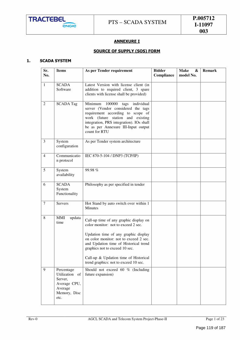
PTS – SCADA SYSTEM
P.005712
I-11097
003
Rev-0 AGCL SCADA and Telecom System Project-Phase-II Page 1 of 23
ANNEXURE I
SOURCE OF SUPPLY (SOS) FORM
1. SCADA SYSTEM
Sr.
No.
Items As per Tender requirement Bidder
Compliance
Make &
model No.
Remark
1 SCADA
Software
Latest Version with license client (in
addition to required client, 3 spare
clients with license shall be provided)
2 SCADA Tag Minimum 100000 tags individual
server (Vendor considered the tags
requirement according to scope of
work (future station and existing
integration, PRS integration). IOs shall
be as per Annexure III-Input output
count for RTU
3 System
configuration
As per Tender system architecture
4 Communicatio
n protocol
IEC 870-5-104 / DNP3 (TCP/IP)
5 System
availability
99.98 %
6 SCADA
System
Functionality
Philosophy as per specified in tender
7 Servers Hot Stand by auto switch over within 1
Minutes
8 MMI updata
time Call-up time of any graphic display on
color monitor: not to exceed 2 sec.
Updation time of any graphic display
on color monitor: not to exceed 2 sec.
and Updation time of Historical trend
graphics not to exceed 10 sec.
Call-up & Updation time of Historical
trend graphics: not to exceed 10 sec.
9 Percentage
Utilization of
Server,
Average CPU,
Average
Memory, Disc
etc.
Should not exceed 60 % (Including
future expansion)
Page 119 of 187
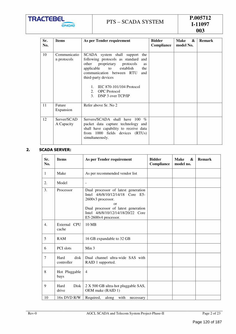
PTS – SCADA SYSTEM
P.005712
I-11097
003
Rev-0 AGCL SCADA and Telecom System Project-Phase-II Page 2 of 23
Sr.
No.
Items As per Tender requirement Bidder
Compliance
Make &
model No.
Remark
10 Communicatio
n protocols
SCADA system shall support the
following protocols as standard and
other proprietary protocols as
applicable to establish the
communication between RTU and
third-party devices
1. IEC 870-101/104 Protocol
2. OPC Protocol
3. DNP 3 over TCP/IP
11 Future
Expansion
Refer above Sr. No 2
12 Server/SCAD
A Capacity
Servers/SCADA shall have 100 %
packet data capture technology and
shall have capability to receive data
from 1000 fields devices (RTUs)
simultaneously.
2. SCADA SERVER:
Sr.
No.
Items As per Tender requirement Bidder
Compliance
Make &
model no.
Remark
1 Make As per recommended vendor list
2. Model -
3. Processor Dual processor of latest generation
Intel 4/6/8/10/12/14/18 Core E5-
2600v3 processor.
or
Dual processor of latest generation
Intel 4/6/8/10/12/14/18/20/22 Core
E5-2600v4 processor.
4. External CPU
cache
10 MB
5 RAM 16 GB expandable to 32 GB
6 PCI slots Min 3
7 Hard disk
controller
Dual channel ultra-wide SAS with
RAID 1 supported.
8 Hot Pluggable
bays
4
9 Hard Disk
drive
2 X 500 GB ultra-hot pluggable SAS,
OEM make (RAID 1)
10 16x DVD R/W Required, along with necessary
Page 120 of 187
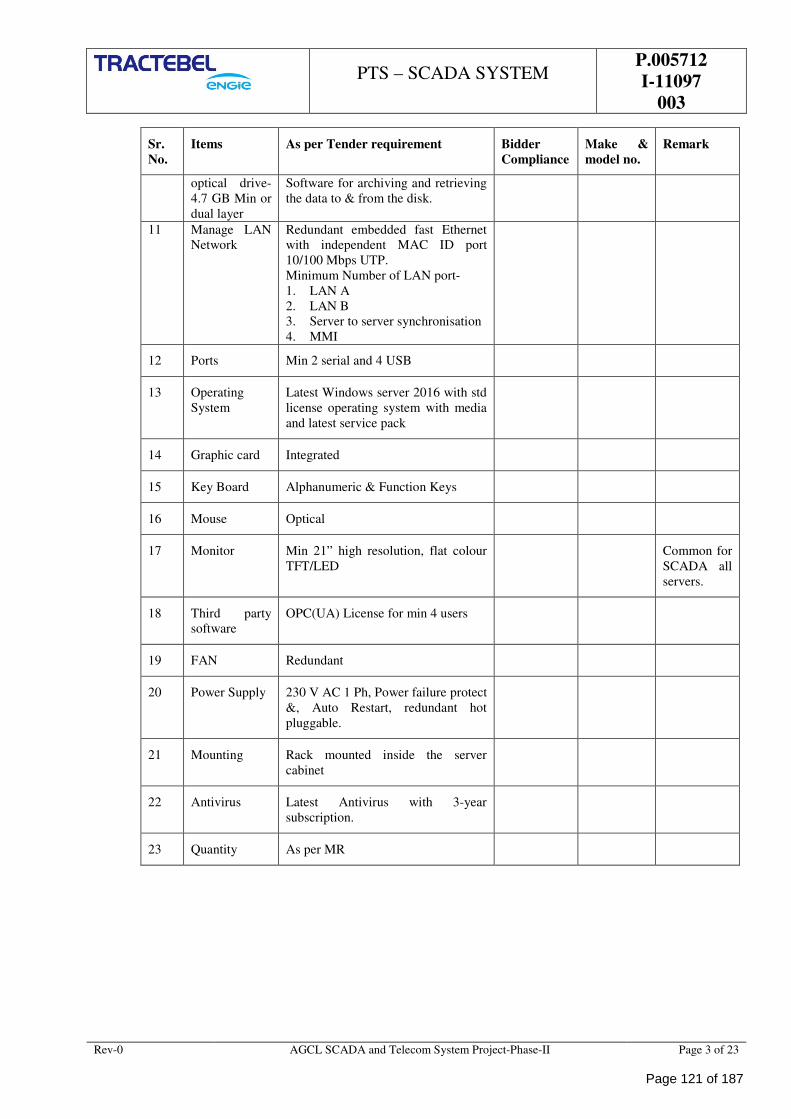
PTS – SCADA SYSTEM
P.005712
I-11097
003
Rev-0 AGCL SCADA and Telecom System Project-Phase-II Page 3 of 23
Sr.
No.
Items As per Tender requirement Bidder
Compliance
Make &
model no.
Remark
optical drive-
4.7 GB Min or
dual layer
Software for archiving and retrieving
the data to & from the disk.
11 Manage LAN
Network
Redundant embedded fast Ethernet
with independent MAC ID port
10/100 Mbps UTP.
Minimum Number of LAN port-
1. LAN A
2. LAN B
3. Server to server synchronisation
4. MMI
12 Ports Min 2 serial and 4 USB
13 Operating
System
Latest Windows server 2016 with std
license operating system with media
and latest service pack
14 Graphic card Integrated
15 Key Board Alphanumeric & Function Keys
16 Mouse Optical
17 Monitor Min 21” high resolution, flat colour
TFT/LED
Common for
SCADA all
servers.
18 Third party
software
OPC(UA) License for min 4 users
19 FAN Redundant
20 Power Supply 230 V AC 1 Ph, Power failure protect
&, Auto Restart, redundant hot
pluggable.
21 Mounting Rack mounted inside the server
cabinet
22 Antivirus Latest Antivirus with 3-year
subscription.
23 Quantity As per MR
Page 121 of 187
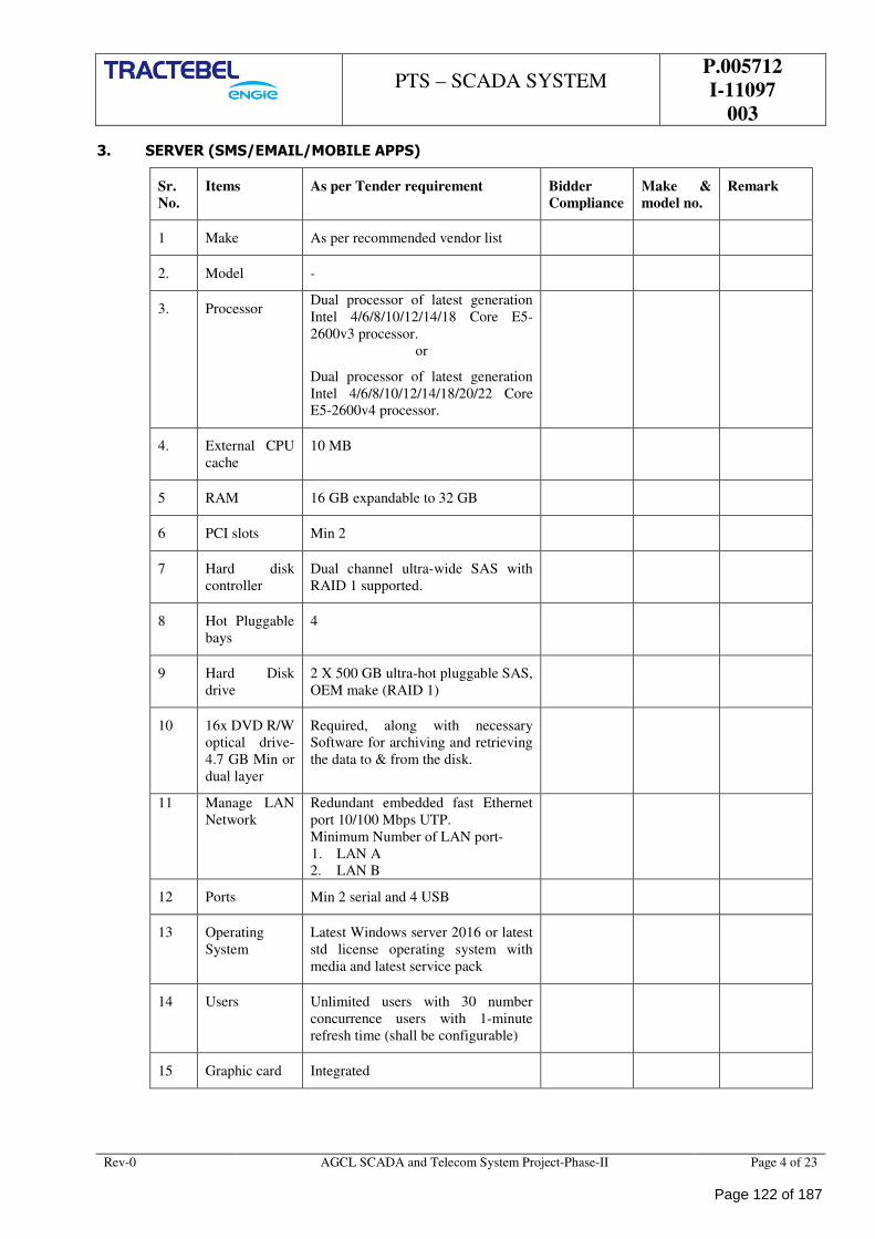
PTS – SCADA SYSTEM
P.005712
I-11097
003
Rev-0 AGCL SCADA and Telecom System Project-Phase-II Page 4 of 23
3. SERVER (SMS/EMAIL/MOBILE APPS)
Sr.
No.
Items As per Tender requirement Bidder
Compliance
Make &
model no.
Remark
1 Make As per recommended vendor list
2. Model -
3. Processor Dual processor of latest generation
Intel 4/6/8/10/12/14/18 Core E5-
2600v3 processor.
or
Dual processor of latest generation
Intel 4/6/8/10/12/14/18/20/22 Core
E5-2600v4 processor.
4. External CPU
cache
10 MB
5 RAM 16 GB expandable to 32 GB
6 PCI slots Min 2
7 Hard disk
controller
Dual channel ultra-wide SAS with
RAID 1 supported.
8 Hot Pluggable
bays
4
9 Hard Disk
drive
2 X 500 GB ultra-hot pluggable SAS,
OEM make (RAID 1)
10 16x DVD R/W
optical drive-
4.7 GB Min or
dual layer
Required, along with necessary
Software for archiving and retrieving
the data to & from the disk.
11 Manage LAN
Network
Redundant embedded fast Ethernet
port 10/100 Mbps UTP.
Minimum Number of LAN port-
1. LAN A
2. LAN B
12 Ports Min 2 serial and 4 USB
13 Operating
System
Latest Windows server 2016 or latest
std license operating system with
media and latest service pack
14 Users Unlimited users with 30 number
concurrence users with 1-minute
refresh time (shall be configurable)
15 Graphic card Integrated
Page 122 of 187
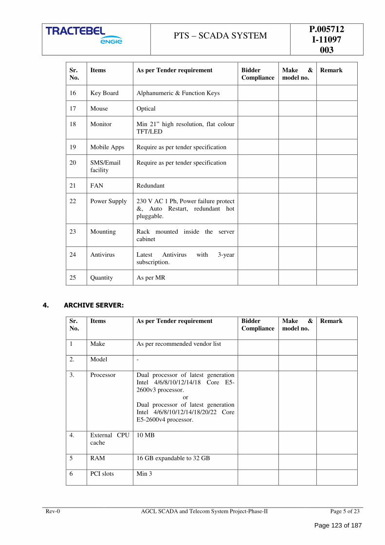
PTS – SCADA SYSTEM
P.005712
I-11097
003
Rev-0 AGCL SCADA and Telecom System Project-Phase-II Page 5 of 23
Sr.
No.
Items As per Tender requirement Bidder
Compliance
Make &
model no.
Remark
16 Key Board Alphanumeric & Function Keys
17 Mouse Optical
18 Monitor Min 21” high resolution, flat colour
TFT/LED
19 Mobile Apps Require as per tender specification
20 SMS/Email
facility
Require as per tender specification
21 FAN Redundant
22 Power Supply 230 V AC 1 Ph, Power failure protect
&, Auto Restart, redundant hot
pluggable.
23 Mounting Rack mounted inside the server
cabinet
24 Antivirus Latest Antivirus with 3-year
subscription.
25 Quantity As per MR
4. ARCHIVE SERVER:
Sr.
No.
Items As per Tender requirement Bidder
Compliance
Make &
model no.
Remark
1 Make As per recommended vendor list
2. Model -
3. Processor Dual processor of latest generation
Intel 4/6/8/10/12/14/18 Core E5-
2600v3 processor.
or
Dual processor of latest generation
Intel 4/6/8/10/12/14/18/20/22 Core
E5-2600v4 processor.
4. External CPU
cache
10 MB
5 RAM 16 GB expandable to 32 GB
6 PCI slots Min 3
Page 123 of 187
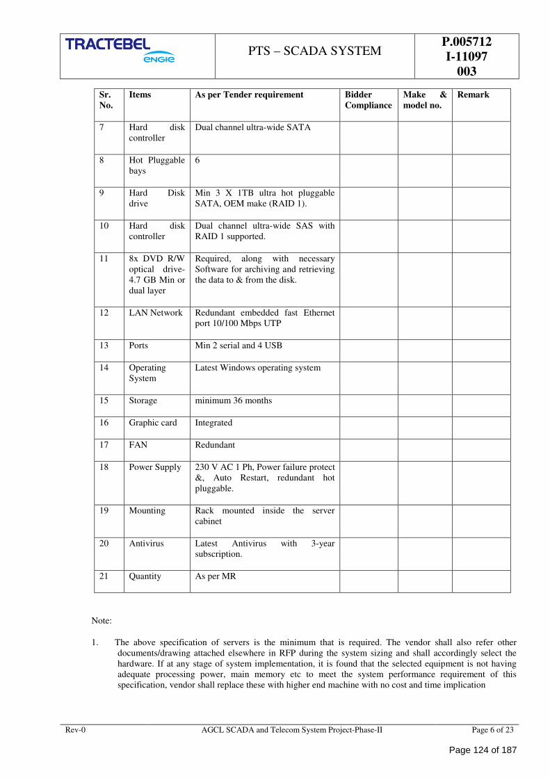
PTS – SCADA SYSTEM
P.005712
I-11097
003
Rev-0 AGCL SCADA and Telecom System Project-Phase-II Page 6 of 23
Sr.
No.
Items As per Tender requirement Bidder
Compliance
Make &
model no.
Remark
7 Hard disk
controller
Dual channel ultra-wide SATA
8 Hot Pluggable
bays
6
9 Hard Disk
drive
Min 3 X 1TB ultra hot pluggable
SATA, OEM make (RAID 1).
10 Hard disk
controller
Dual channel ultra-wide SAS with
RAID 1 supported.
11 8x DVD R/W
optical drive-
4.7 GB Min or
dual layer
Required, along with necessary
Software for archiving and retrieving
the data to & from the disk.
12 LAN Network Redundant embedded fast Ethernet
port 10/100 Mbps UTP
13 Ports Min 2 serial and 4 USB
14 Operating
System
Latest Windows operating system
15 Storage minimum 36 months
16 Graphic card Integrated
17 FAN Redundant
18 Power Supply 230 V AC 1 Ph, Power failure protect
&, Auto Restart, redundant hot
pluggable.
19 Mounting Rack mounted inside the server
cabinet
20 Antivirus Latest Antivirus with 3-year
subscription.
21 Quantity As per MR
Note:
1. The above specification of servers is the minimum that is required. The vendor shall also refer other
documents/drawing attached elsewhere in RFP during the system sizing and shall accordingly select the
hardware. If at any stage of system implementation, it is found that the selected equipment is not having
adequate processing power, main memory etc to meet the system performance requirement of this
specification, vendor shall replace these with higher end machine with no cost and time implication
Page 124 of 187
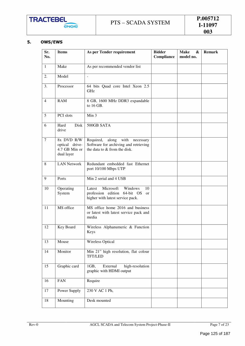
PTS – SCADA SYSTEM
P.005712
I-11097
003
Rev-0 AGCL SCADA and Telecom System Project-Phase-II Page 7 of 23
5. OWS/EWS
Sr.
No.
Items As per Tender requirement Bidder
Compliance
Make &
model no.
Remark
1 Make As per recommended vendor list
2. Model -
3. Processor 64 bits Quad core Intel Xeon 2.5
GHz
4 RAM 8 GB, 1600 MHz DDR3 expandable
to 16 GB.
5 PCI slots Min 3
6 Hard Disk
drive
500GB SATA
7 8x DVD R/W
optical drive-
4.7 GB Min or
dual layer
Required, along with necessary
Software for archiving and retrieving
the data to & from the disk.
8 LAN Network Redundant embedded fast Ethernet
port 10/100 Mbps UTP
9 Ports Min 2 serial and 4 USB
10 Operating
System
Latest Microsoft Windows 10
profession edition 64-bit OS or
higher with latest service pack.
11 MS office MS office home 2016 and business
or latest with latest service pack and
media
12 Key Board Wireless Alphanumeric & Function
Keys
13 Mouse Wireless Optical
14 Monitor Min 21” high resolution, flat colour
TFT/LED
15 Graphic card 1GB, External high-resolution
graphic with HDMI output
16 FAN Require
17 Power Supply 230 V AC 1 Ph,
18 Mounting Desk mounted
Page 125 of 187
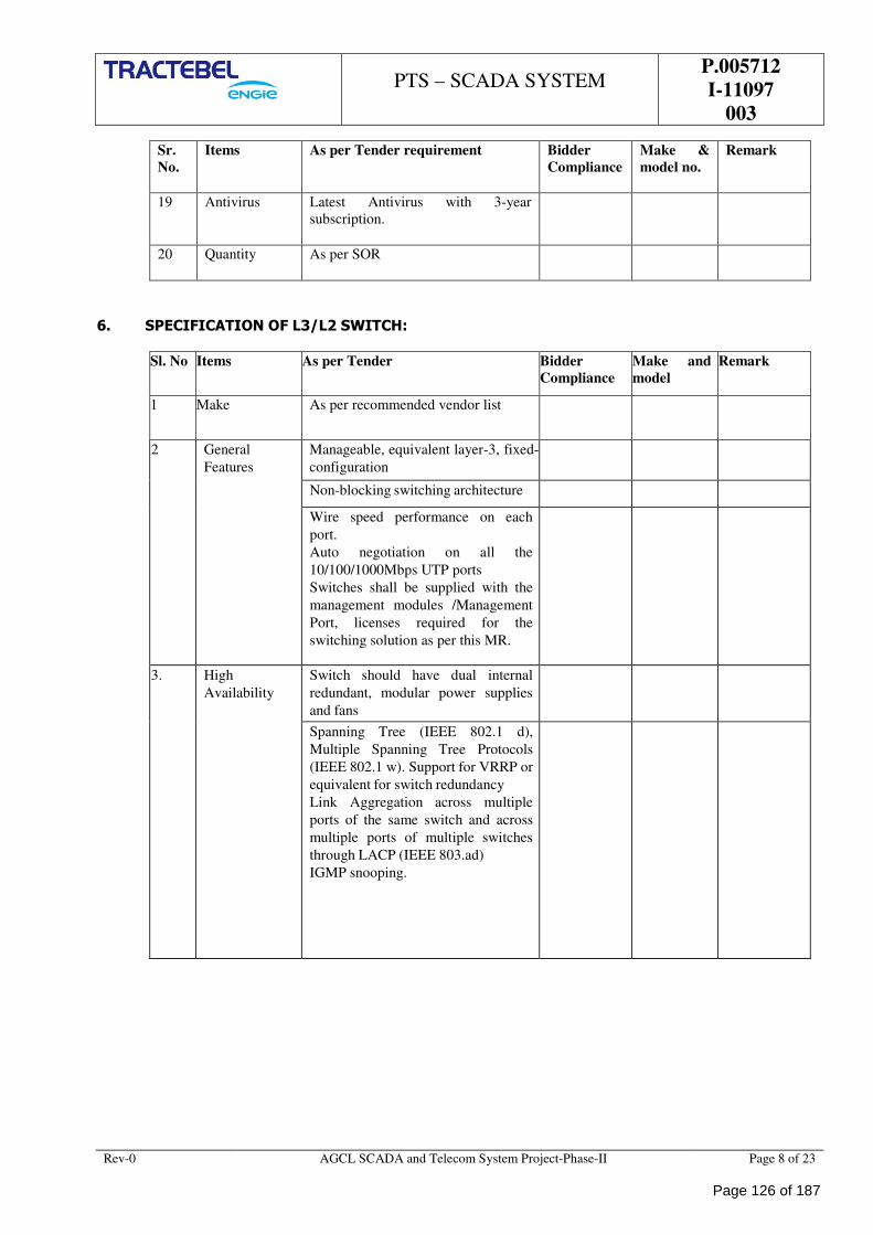
PTS – SCADA SYSTEM
P.005712
I-11097
003
Rev-0 AGCL SCADA and Telecom System Project-Phase-II Page 8 of 23
Sr.
No.
Items As per Tender requirement Bidder
Compliance
Make &
model no.
Remark
19 Antivirus Latest Antivirus with 3-year
subscription.
20 Quantity As per SOR
6. SPECIFICATION OF L3/L2 SWITCH:
Sl. No Items As per Tender Bidder
Compliance
Make and
model
Remark
1 Make As per recommended vendor list
2 General
Features
Manageable, equivalent layer-3, fixed-
configuration
Non-blocking switching architecture
Wire speed performance on each
port.
Auto negotiation on all the
10/100/1000Mbps UTP ports
Switches shall be supplied with the
management modules /Management
Port, licenses required for the
switching solution as per this MR.
3. High
Availability
Switch should have dual internal
redundant, modular power supplies
and fans
Spanning Tree (IEEE 802.1 d),
Multiple Spanning Tree Protocols
(IEEE 802.1 w). Support for VRRP or
equivalent for switch redundancy
Link Aggregation across multiple
ports of the same switch and across
multiple ports of multiple switches
through LACP (IEEE 803.ad)
IGMP snooping.
Page 126 of 187
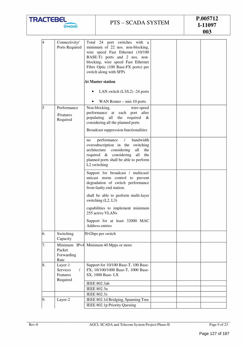
PTS – SCADA SYSTEM
P.005712
I-11097
003
Rev-0 AGCL SCADA and Telecom System Project-Phase-II Page 9 of 23
4 Connectivity/
Ports Required
Total 24 port switches with a
minimum of 22 nos. non-blocking,
wire speed Fast Ethernet (10/100
BASE-T) ports and 2 nos. non-
blocking, wire speed Fast Ethernet
Fibre Optic (100 Base-FX ports) per
switch along with SFPs
At Master station
• LAN switch (L3/L2) -24 ports
• WAN Router – min 10 ports
5 Performance
/Features
Required
Non-blocking, wire-speed
performance at each port after
populating all the required &
considering all the planned ports
Broadcast suppression functionalities
no performance / bandwidth
oversubscription in the switching
architecture considering all the
required & considering all the
planned ports shall be able to perform
L2 switching
Support for broadcast / multicast/
unicast storm control to prevent
degradation of switch performance
from faulty end station.
shall be able to perform multi-layer
switching (L2, L3)
capabilities to implement minimum
255 active VLANs
Support for at least 32000 MAC
Address entries
6. Switching
Capacity
50 Gbps per switch
7. Minimum IPv4
Packet
Forwarding
Rate
Minimum 40 Mpps or more
8. Layer-1
Services /
Features
Required
Support for 10/100 Base-T, 100 Base-
FX, 10/100/1000 Base-T, 1000 Base-
SX, 1000 Base- LX
IEEE 802.3ab
IEEE 802.3u
IEEE 802.3z
9. Layer-2 IEEE 802.1d Bridging, Spanning Tree
IEEE 802.1p Priority Queuing
Page 127 of 187
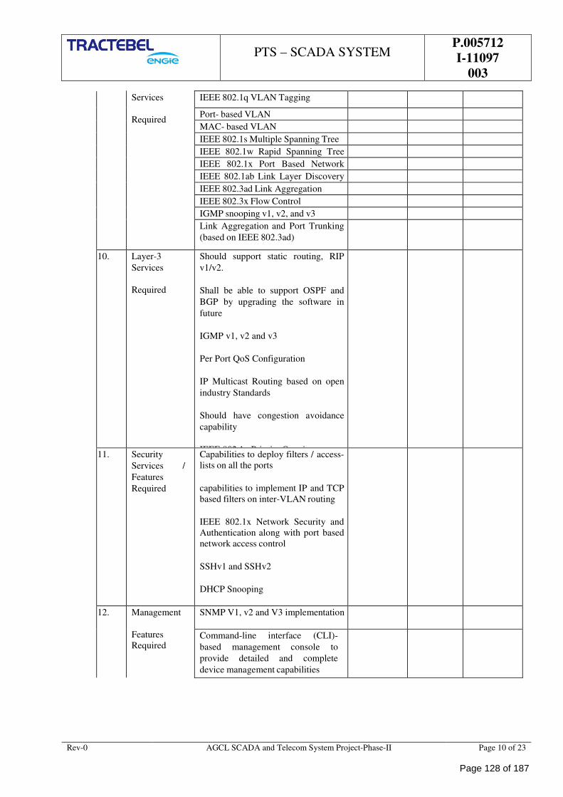
PTS – SCADA SYSTEM
P.005712
I-11097
003
Rev-0 AGCL SCADA and Telecom System Project-Phase-II Page 10 of 23
Services
Required
IEEE 802.1q VLAN Tagging
Port- based VLAN
MAC- based VLAN
IEEE 802.1s Multiple Spanning Tree
IEEE 802.1w Rapid Spanning Tree
IEEE 802.1x Port Based Network
IEEE 802.1ab Link Layer Discovery
IEEE 802.3ad Link Aggregation
IEEE 802.3x Flow Control
IGMP snooping v1, v2, and v3
Link Aggregation and Port Trunking
(based on IEEE 802.3ad)
10. Layer-3
Services
Required
Should support static routing, RIP
v1/v2.
Shall be able to support OSPF and
BGP by upgrading the software in
future
IGMP v1, v2 and v3
Per Port QoS Configuration
IP Multicast Routing based on open
industry Standards
Should have congestion avoidance
capability
IEEE 802.1p Priority Queuing
11. Security
Services /
Features
Required
Capabilities to deploy filters / access-
lists on all the ports
capabilities to implement IP and TCP
based filters on inter-VLAN routing
IEEE 802.1x Network Security and
Authentication along with port based
network access control
SSHv1 and SSHv2
DHCP Snooping
12. Management
Features
Required
SNMP V1, v2 and V3 implementation
Command-line interface (CLI)-
based management console to
provide detailed and complete
device management capabilities
Page 128 of 187
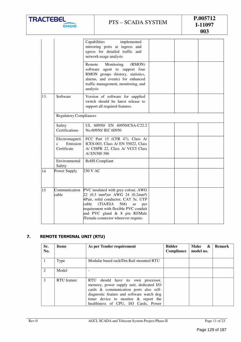
PTS – SCADA SYSTEM
P.005712
I-11097
003
Rev-0 AGCL SCADA and Telecom System Project-Phase-II Page 11 of 23
Capabilities implemented
mirroring ports at ingress and
egress for detailed traffic and
network usage analysis
Remote Monitoring (RMON)
software agent to support four
RMON groups (history, statistics,
alarms, and events) for enhanced
traffic management, monitoring, and
analysis
13. Software Version of software for supplied
switch should be latest release to
support all required features.
Regulatory Compliances
Safety
Certifications
UL 60950/ EN 60950/CSA-C22.2
No.60950/ IEC 60950
Electromagneti
c Emission
Certificate
FCC Part 15 (CFR 47), Class A/
ICES-003, Class A/ EN 55022, Class
A/ CISPR 22, Class A/ VCCI Class
A/ EN300 386
Environmental
Safety
RoHS Compliant
14 Power Supply 230 V AC
15 Communication
cable
PVC insulated with grey colour, AWG
22 (0.3 mm²)or AWG 24 (0.2mm²)
4Pair, solid conductor, CAT 5e, UTP
cable (TIA/EIA 568) as per
requirement with flexible PVC conduit
and PVC gland & 8 pin RJ/Male
/Female connector wherever require.
7. REMOTE TERMINAL UNIT (RTU)
Sr.
No.
Items As per Tender requirement Bidder
Compliance
Make &
model no.
Remark
1 Type Modular based rack/Din Rail mounted RTU
2 Model -
3 RTU feature RTU should have its own processor,
memory, power supply unit, dedicated I/O
cards & communication ports also self-
diagnostic feature and software watch dog
timer device to monitor & report the
healthiness of CPU, I/O Cards, Power
Page 129 of 187
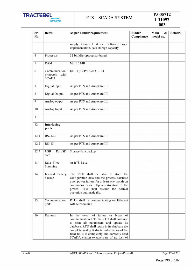
PTS – SCADA SYSTEM
P.005712
I-11097
003
Rev-0 AGCL SCADA and Telecom System Project-Phase-II Page 12 of 23
Sr.
No.
Items As per Tender requirement Bidder
Compliance
Make &
model no.
Remark
supply, Comm Unit etc. Software Logic
implementation, data storage capacity.
4 Processor 32-bit Microprocessor based.
5 RAM Min 16 MB
6 Communication
protocols with
SCADA
DNP3 (TCP/IP) /IEC -104
7 Digital Input As per PTS and Annexure III
8 Digital Output As per PTS and Annexure III
9 Analog output As per PTS and Annexure III
10 Analog Input As per PTS and Annexure III
11
12 Interfacing
ports
12.1 RS232C As per PTS and Annexure III
12.2 RS485 As per PTS and Annexure III
12.3 USB Port/SD
card
Storage data backup
13 Data Time
Stamping
At RTU Level
14 Internal battery
backup
The RTU shall be able to store the
configuration data and the process database
upon power failure for at least one month on
continuous basis. Upon restoration of the
power, RTU shall resume the normal
operation automatically.
15 Communication
ports
RTUs shall be communicating on Ethernet
with telecom unit.
16 Features In the event of failure or break of
communication link, the RTU shall continue
to scan all parameters and update its
database. RTU shall retain in its database the
complete analog & digital information of the
field till it is completely and correctly read
SCADA station to take care of no loss of
Page 130 of 187
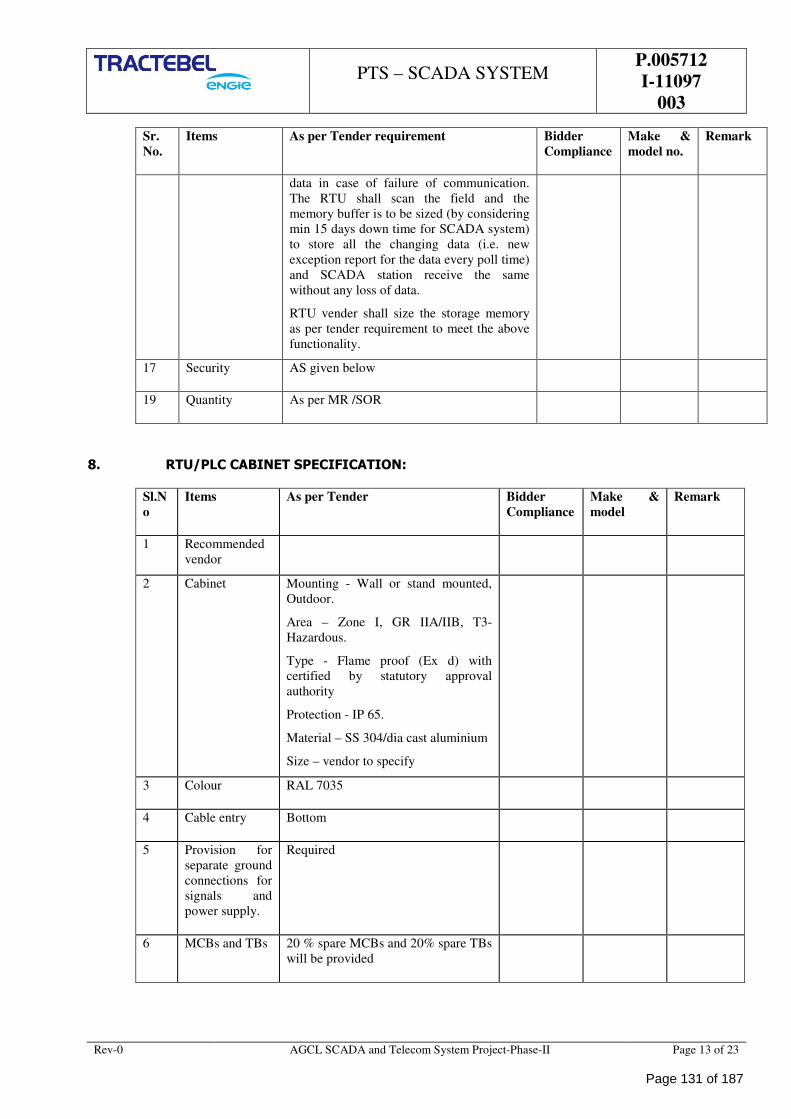
PTS – SCADA SYSTEM
P.005712
I-11097
003
Rev-0 AGCL SCADA and Telecom System Project-Phase-II Page 13 of 23
Sr.
No.
Items As per Tender requirement Bidder
Compliance
Make &
model no.
Remark
data in case of failure of communication.
The RTU shall scan the field and the
memory buffer is to be sized (by considering
min 15 days down time for SCADA system)
to store all the changing data (i.e. new
exception report for the data every poll time)
and SCADA station receive the same
without any loss of data.
RTU vender shall size the storage memory
as per tender requirement to meet the above
functionality.
17 Security AS given below
19 Quantity As per MR /SOR
8. RTU/PLC CABINET SPECIFICATION:
Sl.N
o
Items As per Tender Bidder
Compliance
Make &
model
Remark
1 Recommended
vendor
2 Cabinet Mounting - Wall or stand mounted,
Outdoor.
Area – Zone I, GR IIA/IIB, T3-
Hazardous.
Type - Flame proof (Ex d) with
certified by statutory approval
authority
Protection - IP 65.
Material – SS 304/dia cast aluminium
Size – vendor to specify
3 Colour RAL 7035
4 Cable entry Bottom
5 Provision for
separate ground
connections for
signals and
power supply.
Required
6 MCBs and TBs 20 % spare MCBs and 20% spare TBs
will be provided
Page 131 of 187
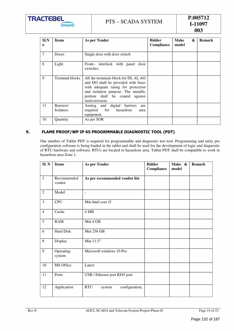
PTS – SCADA SYSTEM
P.005712
I-11097
003
Rev-0 AGCL SCADA and Telecom System Project-Phase-II Page 14 of 23
Sl.N
o
Items As per Tender Bidder
Compliance
Make &
model
Remark
7 Doors Single door with door switch
8 Light Front– interlock with panel door
switches.
9 Terminal blocks All the terminals block for DI, AI, AO
and DO shall be provided with fuses
with adequate rating for protection
and isolation purpose. The metallic
portion shall be coated against
rust/corrosion.
11 Barriers/
Isolators
Analog and digital barriers are
required for hazardous area
equipment.
10 Quantity As per SOR
9. FLAME PROOF/WP IP 65 PROGRMMABLE DIAGNOSTIC TOOL (PDT)
One number of Tablet PDT is required for programmable and diagnostic test tool. Programming and unity pro
configuration software is being loaded in the tablet and shall be used for the development of logic and diagnostic
of RTU hardware and software. RTUs are located in hazardous area. Tablet PDT shall be compatible to work in
hazardous area Zone 1.
Sl. N Items As per Tender Bidder
Compliance
Make &
model
Remark
1 Recommended
vendor As per recommended vendor list
2 Model -
3 CPU Min Intel core i5
4 Cache 4 MB
5 RAM Min 4 GB
6 Hard Disk Min 256 GB
8 Display Min 11.5”
9 Operating
system
Microsoft windows 10 Pro
10 MS Office Latest
11 Ports USB / Ethernet port RJ45 port
12 Application RTU system configuration,
Page 132 of 187
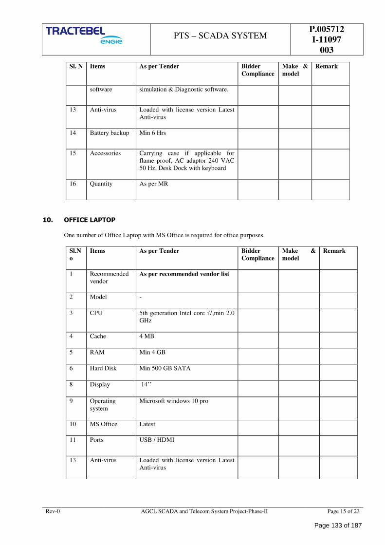
PTS – SCADA SYSTEM
P.005712
I-11097
003
Rev-0 AGCL SCADA and Telecom System Project-Phase-II Page 15 of 23
Sl. N Items As per Tender Bidder
Compliance
Make &
model
Remark
software simulation & Diagnostic software.
13 Anti-virus Loaded with license version Latest
Anti-virus
14 Battery backup Min 6 Hrs
15 Accessories Carrying case if applicable for
flame proof, AC adaptor 240 VAC
50 Hz, Desk Dock with keyboard
16 Quantity As per MR
10. OFFICE LAPTOP
One number of Office Laptop with MS Office is required for office purposes.
Sl.N
o
Items As per Tender Bidder
Compliance
Make &
model
Remark
1 Recommended
vendor As per recommended vendor list
2 Model -
3 CPU 5th generation Intel core i7,min 2.0
GHz
4 Cache 4 MB
5 RAM Min 4 GB
6 Hard Disk Min 500 GB SATA
8 Display 14’’
9 Operating
system
Microsoft windows 10 pro
10 MS Office Latest
11 Ports USB / HDMI
13 Anti-virus Loaded with license version Latest
Anti-virus
Page 133 of 187
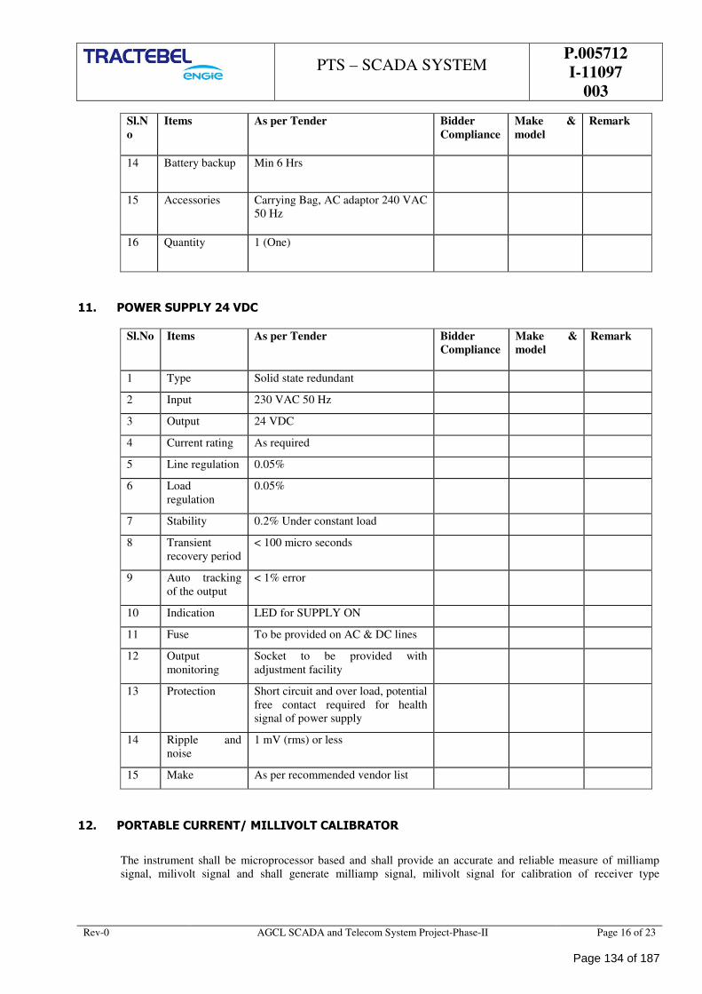
PTS – SCADA SYSTEM
P.005712
I-11097
003
Rev-0 AGCL SCADA and Telecom System Project-Phase-II Page 16 of 23
Sl.N
o
Items As per Tender Bidder
Compliance
Make &
model
Remark
14 Battery backup Min 6 Hrs
15 Accessories Carrying Bag, AC adaptor 240 VAC
50 Hz
16 Quantity 1 (One)
11. POWER SUPPLY 24 VDC
Sl.No Items As per Tender Bidder
Compliance
Make &
model
Remark
1 Type Solid state redundant
2 Input 230 VAC 50 Hz
3 Output 24 VDC
4 Current rating As required
5 Line regulation 0.05%
6 Load
regulation
0.05%
7 Stability 0.2% Under constant load
8 Transient
recovery period
< 100 micro seconds
9 Auto tracking
of the output
< 1% error
10 Indication LED for SUPPLY ON
11 Fuse To be provided on AC & DC lines
12 Output
monitoring
Socket to be provided with
adjustment facility
13 Protection Short circuit and over load, potential
free contact required for health
signal of power supply
14 Ripple and
noise
1 mV (rms) or less
15 Make As per recommended vendor list
12. PORTABLE CURRENT/ MILLIVOLT CALIBRATOR
The instrument shall be microprocessor based and shall provide an accurate and reliable measure of milliamp
signal, milivolt signal and shall generate milliamp signal, milivolt signal for calibration of receiver type
Page 134 of 187
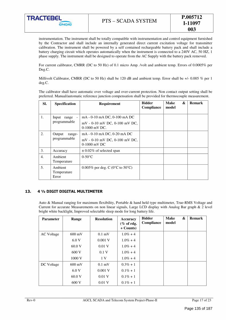
PTS – SCADA SYSTEM
P.005712
I-11097
003
Rev-0 AGCL SCADA and Telecom System Project-Phase-II Page 17 of 23
instrumentation. The instrument shall be totally compatible with instrumentation and control equipment furnished
by the Contractor and shall include an internally generated direct current excitation voltage for transmitter
calibration. The instrument shall be powered by a self contained rechargeable battery pack and shall include a
battery charging circuit which operates automatically when the instrument is connected to a 240V AC, 50 HZ, 1
phase supply. The instrument shall be designed to operate from the AC Supply with the battery pack removed.
For current calibrator, CMRR (DC to 50 Hz) of 0.1 micro Amp. /volt and ambient temp. Errors of 0.0005% per
Deg.C.
Millivolt Calibrator, CMRR (DC to 50 Hz) shall be 120 dB and ambient temp. Error shall be +/- 0.005 % per 1
deg.C.
The calibrator shall have automatic over voltage and over-current protection. Non contact output setting shall be
preferred. Manual/automatic reference junction compensation shall be provided for thermocouple measurement.
Sl. Specification Requirement Bidder
Compliance
Make &
model
Remark
1. Input range -
programmable
mA - 0-10 mA DC, 0-100 mA DC
mV - 0-10 mV DC, 0-100 mV DC,
0-1000 mV DC.
2. Output range-
programmable
mA - 0-10 mA DC, 0-20 mA DC
mV - 0-10 mV DC, 0-100 mV DC,
0-1000 mV DC
3. Accuracy ± 0.02% of selected span
4. Ambient
Temperature
0-50°C
5. Ambient
Temperature
Error
0.005% per deg. C (0°C to 50°C)
13. 4 ½ DIGIT DIGITAL MULTIMETER
Auto & Manual ranging for maximum flexibility, Portable & hand held type multimeter, True-RMS Voltage and
Current for accurate Measurements on non linear signals, Large LCD display with Analog Bar graph & 2 level
bright white backlight, Improved selectable sleep mode for long battery life.
Parameter Range Resolution Accuracy
(% of rdg.
+ Counts)
Bidder
Compliance
Make &
model
Remark
AC Voltage 600 mV
6.0 V
60.0 V
600 V
1000 V
0.1 mV
0.001 V
0.01 V
0.1 V
1 V
1.0% + 4
1.0% + 4
1.0% + 4
1.0% + 4
1.0% + 4
DC Voltage 600 mV
6.0 V
60.0 V
600 V
0.1 mV
0.001 V
0.01 V
0.01 V
0.3% + 1
0.1% + 1
0.1% + 1
0.1% + 1
Page 135 of 187
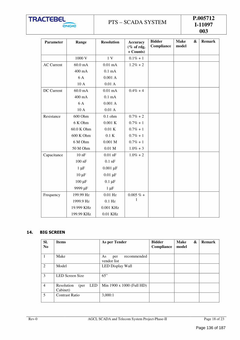
PTS – SCADA SYSTEM
P.005712
I-11097
003
Rev-0 AGCL SCADA and Telecom System Project-Phase-II Page 18 of 23
Parameter Range Resolution Accuracy
(% of rdg.
+ Counts)
Bidder
Compliance
Make &
model
Remark
1000 V 1 V 0.1% + 1
AC Current 60.0 mA
400 mA
6 A
10 A
0.01 mA
0.1 mA
0.001 A
0.01 A
1.2% + 2
DC Current 60.0 mA
400 mA
6 A
10 A
0.01 mA
0.1 mA
0.001 A
0.01 A
0.4% + 4
Resistance 600 Ohm
6 K Ohm
60.0 K Ohm
600 K Ohm
6 M Ohm
50 M Ohm
0.1 ohm
0.001 K
0.01 K
0.1 K
0.001 M
0.01 M
0.7% + 2
0.7% + 1
0.7% + 1
0.7% + 1
0.7% + 1
1.0% + 3
Capacitance 10 nF
100 nF
1 µF
10 µF
100 µF
9999 µF
0.01 nF
0.1 nF
0.001 µF
0.01 µF
0.1 µF
1 µF
1.0% + 2
Frequency 199.99 Hz
1999.9 Hz
19.999 KHz
199.99 KHz
0.01 Hz
0.1 Hz
0.001 KHz
0.01 KHz
0.005 % +
1
14. BIG SCREEN
Sl.
No
Items As per Tender Bidder
Compliance
Make &
model
Remark
1 Make As per recommended
vendor list
2 Model LED Display Wall
3 LED Screen Size 65”
4 Resolution (per LED
Cabinet)
Min 1900 x 1000 (Full HD)
5 Contrast Ratio 3,000:1
Page 136 of 187
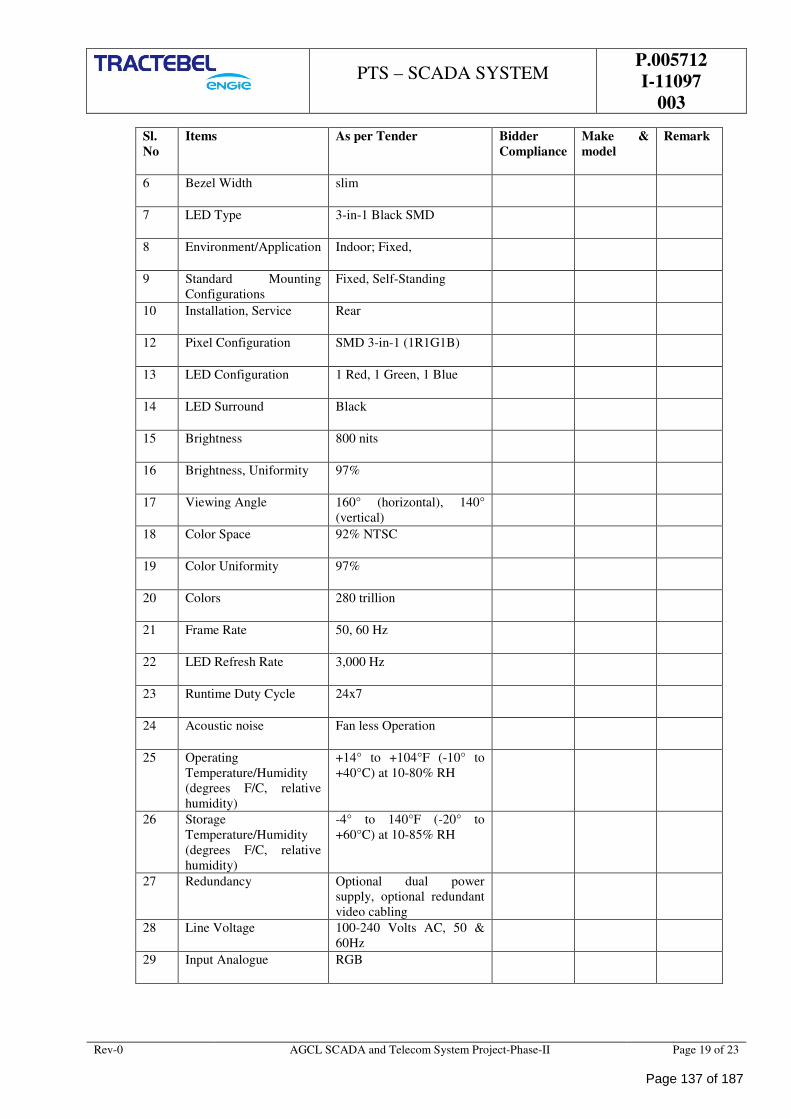
PTS – SCADA SYSTEM
P.005712
I-11097
003
Rev-0 AGCL SCADA and Telecom System Project-Phase-II Page 19 of 23
Sl.
No
Items As per Tender Bidder
Compliance
Make &
model
Remark
6 Bezel Width slim
7 LED Type 3-in-1 Black SMD
8 Environment/Application Indoor; Fixed,
9 Standard Mounting
Configurations
Fixed, Self-Standing
10 Installation, Service Rear
12 Pixel Configuration SMD 3-in-1 (1R1G1B)
13 LED Configuration 1 Red, 1 Green, 1 Blue
14 LED Surround Black
15 Brightness 800 nits
16 Brightness, Uniformity 97%
17 Viewing Angle 160° (horizontal), 140°
(vertical)
18 Color Space 92% NTSC
19 Color Uniformity 97%
20 Colors 280 trillion
21 Frame Rate 50, 60 Hz
22 LED Refresh Rate 3,000 Hz
23 Runtime Duty Cycle 24x7
24 Acoustic noise Fan less Operation
25 Operating
Temperature/Humidity
(degrees F/C, relative
humidity)
+14° to +104°F (-10° to
+40°C) at 10-80% RH
26 Storage
Temperature/Humidity
(degrees F/C, relative
humidity)
-4° to 140°F (-20° to
+60°C) at 10-85% RH
27 Redundancy Optional dual power
supply, optional redundant
video cabling
28 Line Voltage 100-240 Volts AC, 50 &
60Hz
29 Input Analogue RGB
Page 137 of 187
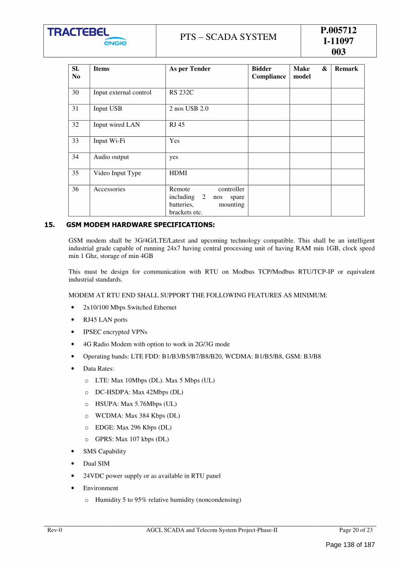
PTS – SCADA SYSTEM
P.005712
I-11097
003
Rev-0 AGCL SCADA and Telecom System Project-Phase-II Page 20 of 23
Sl.
No
Items As per Tender Bidder
Compliance
Make &
model
Remark
30 Input external control RS 232C
31 Input USB 2 nos USB 2.0
32 Input wired LAN RJ 45
33 Input Wi-Fi Yes
34 Audio output yes
35 Video Input Type HDMI
36 Accessories Remote controller
including 2 nos spare
batteries, mounting
brackets etc.
15. GSM MODEM HARDWARE SPECIFICATIONS:
GSM modem shall be 3G/4G/LTE/Latest and upcoming technology compatible. This shall be an intelligent
industrial grade capable of running 24x7 having central processing unit of having RAM min 1GB, clock speed
min 1 Ghz, storage of min 4GB
This must be design for communication with RTU on Modbus TCP/Modbus RTU/TCP-IP or equivalent
industrial standards.
MODEM AT RTU END SHALL SUPPORT THE FOLLOWING FEATURES AS MINIMUM:
• 2x10/100 Mbps Switched Ethernet
• RJ45 LAN ports
• IPSEC encrypted VPNs
• 4G Radio Modem with option to work in 2G/3G mode
• Operating bands: LTE FDD: B1/B3/B5/B7/B8/B20, WCDMA: B1/B5/B8, GSM: B3/B8
• Data Rates:
o LTE: Max 10Mbps (DL). Max 5 Mbps (UL)
o DC-HSDPA: Max 42Mbps (DL)
o HSUPA: Max 5.76Mbps (UL)
o WCDMA: Max 384 Kbps (DL)
o EDGE: Max 296 Kbps (DL)
o GPRS: Max 107 kbps (DL)
• SMS Capability
• Dual SIM
• 24VDC power supply or as available in RTU panel
• Environment
o Humidity 5 to 95% relative humidity (noncondensing)
Page 138 of 187
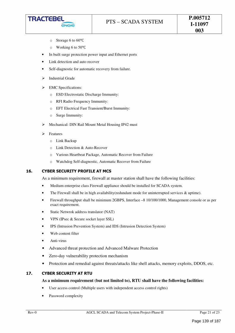
PTS – SCADA SYSTEM
P.005712
I-11097
003
Rev-0 AGCL SCADA and Telecom System Project-Phase-II Page 21 of 23
o Storage 6 to 60
o Working 6 to 50
• In built surge protection power input and Ethernet ports
• Link detection and auto recover
• Self-diagnostic for automatic recovery from failure.
Industrial Grade
EMC Specifications:
o ESD Electrostatic Discharge Immunity:
o RFI Radio Frequency Immunity:
o EFT Electrical Fast Transient/Burst Immunity:
o Surge Immunity:
Mechanical: DIN Rail Mount Metal Housing IP42 must
Features
o Link Backup
o Link Detection & Auto-Recover
o Various Heartbeat Package, Automatic Recover from Failure
o Watchdog Self-diagnostic, Automatic Recover from Failure
16. CYBER SECURITY PROFILE AT MCS
As a minimum requirement, firewall at master station shall have the following facilities:
• Medium enterprise class Firewall appliance should be installed for SCADA system.
• The Firewall shall be in high availability(redundant mode for uninterrupted services & uptime).
• Firewall throughput shall be minimum 2GBPS, Interface –8 10/100/1000, Management console or as per
exact requirement.
• Static Netwrok address translator (NAT)
• VPN (IPsec & Secure socket layer SSL)
• IPS (Intrusion Prevention System) and IDS (Intrusion Detection System)
• Web content filter
• Anti-virus
• Advanced threat protection and Advanced Malware Protection
• Zero-day vulnerability protection mechanism
• Protection and remedial against threats/attacks like shell attacks, memory exploits, DDOS, etc.
17. CYBER SECURITY AT RTU
As a minimum requirement (but not limited to), RTU shall have the following facilities:
• User access control (Multiple users with independent access control rights)
• Password complexity
Page 139 of 187
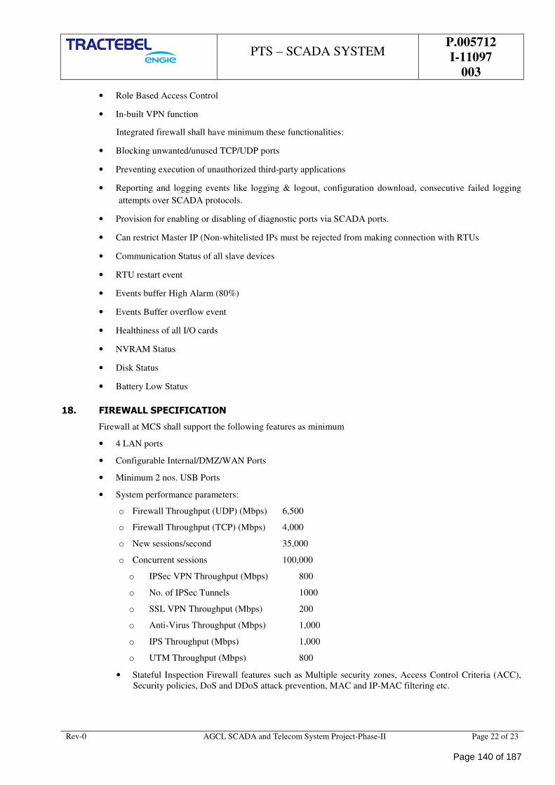
PTS – SCADA SYSTEM
P.005712
I-11097
003
Rev-0 AGCL SCADA and Telecom System Project-Phase-II Page 22 of 23
• Role Based Access Control
• In-built VPN function
Integrated firewall shall have minimum these functionalities:
• Blocking unwanted/unused TCP/UDP ports
• Preventing execution of unauthorized third-party applications
• Reporting and logging events like logging & logout, configuration download, consecutive failed logging
attempts over SCADA protocols.
• Provision for enabling or disabling of diagnostic ports via SCADA ports.
• Can restrict Master IP (Non-whitelisted IPs must be rejected from making connection with RTUs
• Communication Status of all slave devices
• RTU restart event
• Events buffer High Alarm (80%)
• Events Buffer overflow event
• Healthiness of all I/O cards
• NVRAM Status
• Disk Status
• Battery Low Status
18. FIREWALL SPECIFICATION
Firewall at MCS shall support the following features as minimum
• 4 LAN ports
• Configurable Internal/DMZ/WAN Ports
• Minimum 2 nos. USB Ports
• System performance parameters:
o Firewall Throughput (UDP) (Mbps) 6,500
o Firewall Throughput (TCP) (Mbps) 4,000
o New sessions/second 35,000
o Concurrent sessions 100,000
o IPSec VPN Throughput (Mbps) 800
o No. of IPSec Tunnels 1000
o SSL VPN Throughput (Mbps) 200
o Anti-Virus Throughput (Mbps) 1,000
o IPS Throughput (Mbps) 1,000
o UTM Throughput (Mbps) 800
• Stateful Inspection Firewall features such as Multiple security zones, Access Control Criteria (ACC),
Security policies, DoS and DDoS attack prevention, MAC and IP-MAC filtering etc.
Page 140 of 187
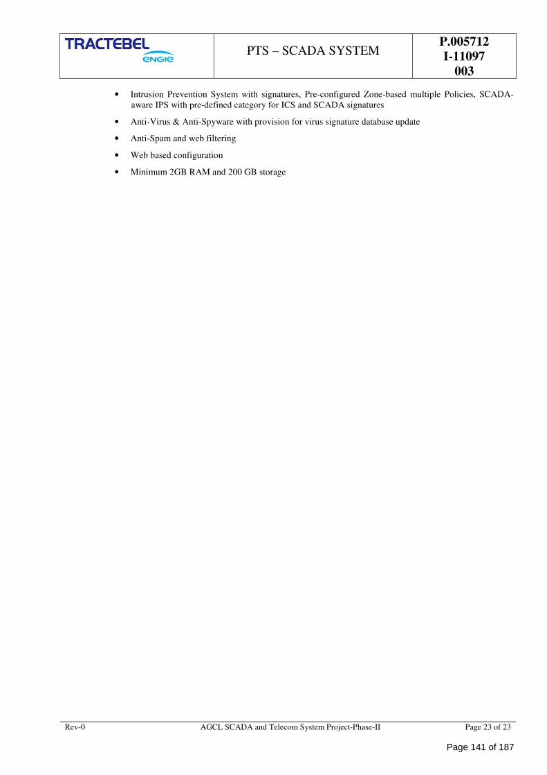
PTS – SCADA SYSTEM
P.005712
I-11097
003
Rev-0 AGCL SCADA and Telecom System Project-Phase-II Page 23 of 23
• Intrusion Prevention System with signatures, Pre-configured Zone-based multiple Policies, SCADA-
aware IPS with pre-defined category for ICS and SCADA signatures
• Anti-Virus & Anti-Spyware with provision for virus signature database update
• Anti-Spam and web filtering
• Web based configuration
• Minimum 2GB RAM and 200 GB storage
Page 141 of 187
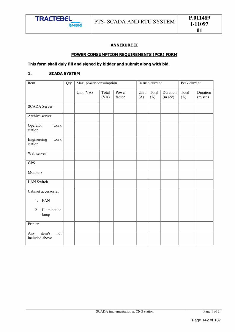
PTS- SCADA AND RTU SYSTEM
P.011489
I-11097
01
SCADA implementation at CNG station Page 1 of 2
ANNEXURE II
POWER CONSUMPTION REQUIREMENTS (PCR) FORM
This form shall duly fill and signed by bidder and submit along with bid.
1. SCADA SYSTEM
Item Qty Max. power consumption In rush current Peak current
Unit (VA) Total
(VA)
Power
factor
Unit
(A)
Total
(A)
Duration
(m sec)
Total
(A)
Duration
(m sec)
SCADA Server
Archive server
Operator work
station
Engineering work
station
Web server
GPS
Monitors
LAN Switch
Cabinet accessories
1. FAN
2. Illumination
lamp
Printer
Any item/s not
included above
Page 142 of 187
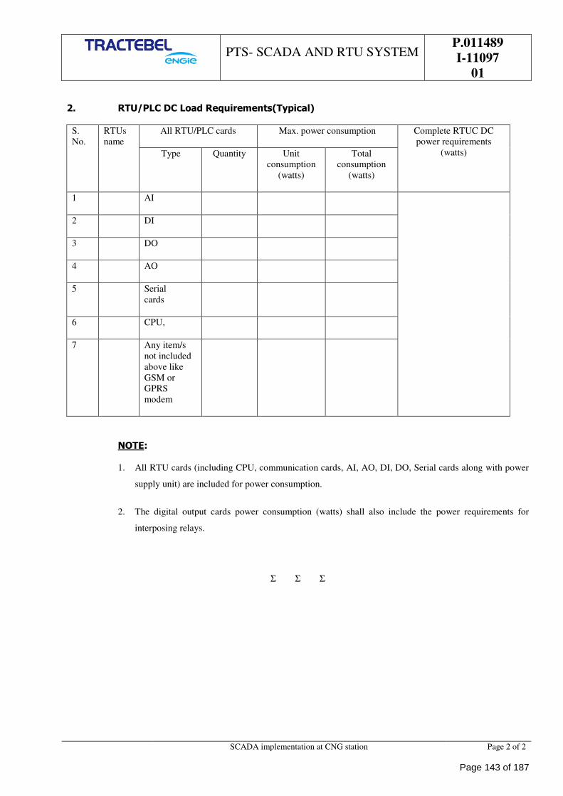
PTS- SCADA AND RTU SYSTEM
P.011489
I-11097
01
SCADA implementation at CNG station Page 2 of 2
2. RTU/PLC DC Load Requirements(Typical)
S.
No.
RTUs
name
All RTU/PLC cards Max. power consumption Complete RTUC DC
power requirements
(watts) Type Quantity Unit
consumption
(watts)
Total
consumption
(watts)
1 AI
2 DI
3 DO
4 AO
5 Serial
cards
6 CPU,
7 Any item/s
not included
above like
GSM or
GPRS
modem
NOTE:
1. All RTU cards (including CPU, communication cards, AI, AO, DI, DO, Serial cards along with power
supply unit) are included for power consumption.
2. The digital output cards power consumption (watts) shall also include the power requirements for
interposing relays.
Σ Σ Σ
Page 143 of 187
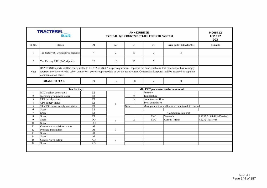
1 Tea factory RTU (Hardwire signals) 4 2 8 2 3
2 Tea Factory RTU (Soft signals) 20 10 10 5
Note
24 12 18 7 3
1 RTU cabinet door status DI 1
2 Incoming grid power status DI 2
3 UPS healthy status DI 3
4 UPS battery status DI 4
5 24 V DC power supply unit status DI Note More parameters shall also be monitored if required
6 Spare DI
7 Spare DI
8 Spare DI 1 EVC Vemtach RS232 & RS 485 (Passive)
9 Spare DO 2 EVC Corous (Itron) RS232 (Passive)
10 Spare DO
11 Control valve poisition stauts AI
12 Pressure transmitter AI
13 Spare AI
14 Spare AI
15 Control valve output AO
16 Spare AO
P.005712
I-11097
003
Station
8
2
Tea Factory
ANNEXURE III
TYPICAL I/O COUNTS DETAILS FOR RTU SYSTEM
RemarksAI AO
Min EVC parameters to be monitored
3
2
Communication port
Pressure
Temperature
Instantaneous flow
Total cumulative
Sl. No.
GRAND TOTAL
RS232/RS485 ports shall be configurable to RS 232 or RS 485 as per requirement. If port is not configurable in that case vendor has to supply
appropriate convertor with cable, connectors, power supply module as per the requirement. Communication ports shall be mounted on separate
communication cards.
DO Serial ports(RS232/RS485)DI
Page 1 of 1
Page 144 of 187
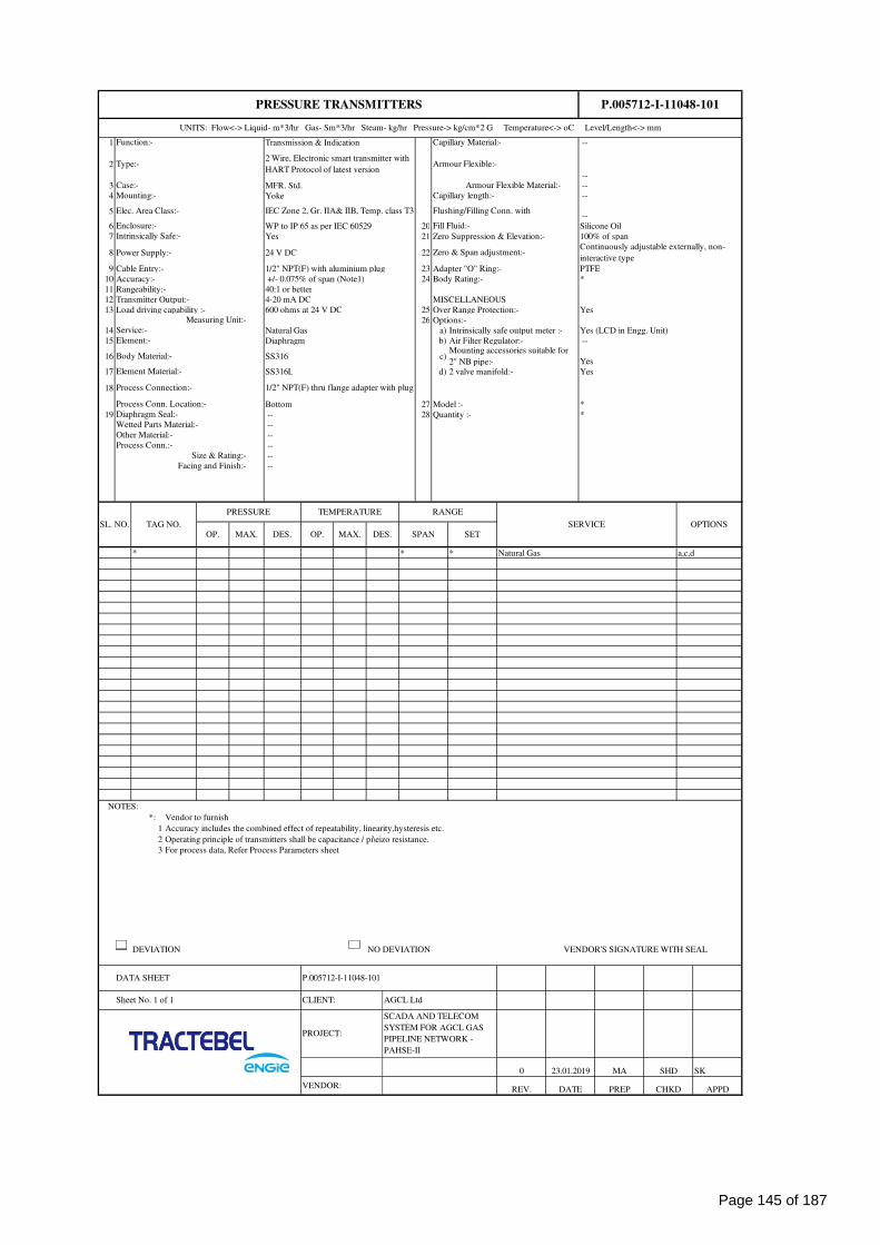
1 Transmission & Indication --
2
--
3 MFR. Std. --
4 Yoke --
5 --
6 WP to IP 65 as per IEC 60529 20 Silicone Oil
7 Yes 21 100% of span
8 Power Supply:- 24 V DC 22
9 Cable Entry:- 1/2" NPT(F) with aluminium plug 23 PTFE
10 Accuracy:- +/- 0.075% of span (Note1) 24 *
11 Rangeability:- 40:1 or better
12 Transmitter Output:- 4-20 mA DC MISCELLANEOUS
13 Load driving capability :- 600 ohms at 24 V DC 25 Over Range Protection:- Yes
26 Options:-
14 Natural Gas a) Intrinsically safe output meter :- Yes (LCD in Engg. Unit)
15 Diaphragm b) Air Filter Regulator:- --
16 SS316 c)Yes
17 SS316L d) 2 valve manifold:- Yes
18
Bottom 27 Model :- *
19 -- 28 Quantity :- *
--
--
--
--
--
* * * Natural Gas a,c,d
NOTES:
*: Vendor to furnish
1 Accuracy includes the combined effect of repeatability, linearity,hysteresis etc.
2 Operating principle of transmitters shall be capacitance / pi\eizo resistance.
3 For process data, Refer Process Parameters sheet
DEVIATION NO DEVIATION VENDOR'S SIGNATURE WITH SEAL
MA SHD SK
VENDOR: REV. DATE PREP CHKD APPD
0 23.01.2019
PROJECT:
SCADA AND TELECOM
SYSTEM FOR AGCL GAS
PIPELINE NETWORK -
PAHSE-II
Sheet No. 1 of 1 CLIENT: AGCL Ltd
DATA SHEET P.005712-I-11048-101
Mounting accessories suitable for
2" NB pipe:-
OPTIONSOP. MAX. DES. OP. MAX. DES. SPAN SET
SL. NO. TAG NO.
PRESSURE TEMPERATURE RANGE
SERVICE
Process Conn.:-
Size & Rating:-
Facing and Finish:-
Diaphragm Seal:-
Wetted Parts Material:-
Other Material:-
Element Material:-
Process Connection:- 1/2" NPT(F) thru flange adapter with plug
Process Conn. Location:-
Measuring Unit:-
Service:-
Element:-
Body Material:-
Zero & Span adjustment:-Continuously adjustable externally, non-
interactive type
Adapter "O" Ring:-
Body Rating:-
Enclosure:- Fill Fluid:-
Intrinsically Safe:- Zero Suppression & Elevation:-
Elec. Area Class:- IEC Zone 2, Gr. IIA& IIB, Temp. class T3 Flushing/Filling Conn. with
Type:-2 Wire, Electronic smart transmitter with
HART Protocol of latest versionArmour Flexible:-
Case:- Armour Flexible Material:-
P.005712-I-11048-101
UNITS: Flow<-> Liquid- m*3/hr Gas- Sm*3/hr Steam- kg/hr Pressure-> kg/cm*2 G Temperature<-> oC Level/Length<-> mm
Function:- Capillary Material:-
Mounting:- Capillary length:-
PRESSURE TRANSMITTERS
Page 145 of 187
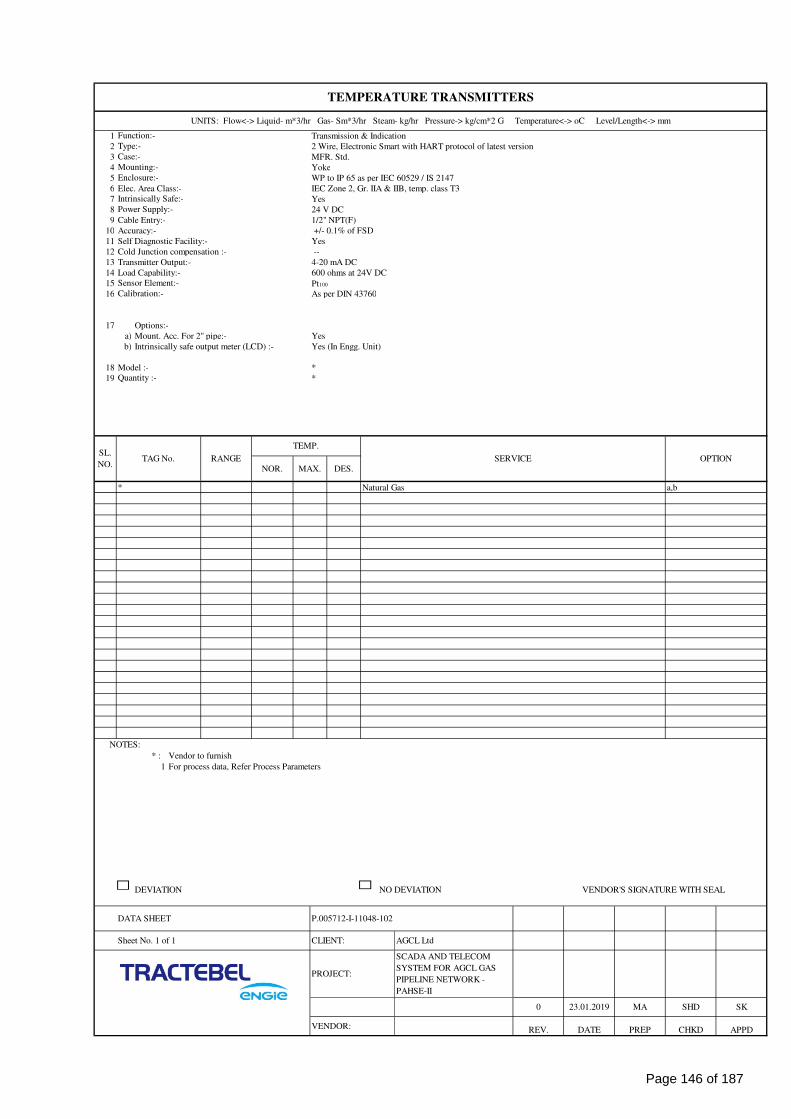
1 Transmission & Indication
2 2 Wire, Electronic Smart with HART protocol of latest version
3 MFR. Std.
4 Yoke
5 WP to IP 65 as per IEC 60529 / IS 2147
6 Elec. Area Class:- IEC Zone 2, Gr. IIA & IIB, temp. class T3
7 Yes
8 24 V DC
9 Cable Entry:- 1/2" NPT(F)
10 Accuracy:- +/- 0.1% of FSD
11 Self Diagnostic Facility:- Yes
12 Cold Junction compensation :- --
13 Transmitter Output:- 4-20 mA DC
14 Load Capability:- 600 ohms at 24V DC
15 Pt100
16 As per DIN 43760
17 Options:-
a) Mount. Acc. For 2" pipe:- Yes
b) Yes (In Engg. Unit)
18 Model :- *
19 *
* Natural Gas a,b
NOTES:
* : Vendor to furnish
1 For process data, Refer Process Parameters
DEVIATION NO DEVIATION VENDOR'S SIGNATURE WITH SEAL
SK
VENDOR: REV. DATE PREP CHKD APPD
SCADA AND TELECOM
SYSTEM FOR AGCL GAS
PIPELINE NETWORK -
PAHSE-II
MA SHD
Sheet No. 1 of 1 CLIENT: AGCL Ltd
0 23.01.2019
PROJECT:
SERVICE OPTION
NOR. MAX. DES.
DATA SHEET P.005712-I-11048-102
SL.
NO.TAG No. RANGE
Intrinsically safe output meter (LCD) :-
Quantity :-
TEMP.
Calibration:-
Case:-
Mounting:-
Enclosure:-
Intrinsically Safe:-
UNITS: Flow<-> Liquid- m*3/hr Gas- Sm*3/hr Steam- kg/hr Pressure-> kg/cm*2 G Temperature<-> oC Level/Length<-> mm
Function:-
Type:-
Power Supply:-
Sensor Element:-
TEMPERATURE TRANSMITTERS
Page 146 of 187
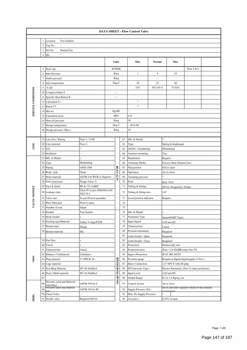
1 Location Tea Gardens
2 Tag No, -
3 Natural Gas
4 Qty. *
5 Flow rate
6 Inlet Pressure
7 Outlet pressure
8 Inlet temperature
9 % lift
10 Compressibility Z
11 Specific Heat Ration K
12 Calculated Cv
13 Rated CV
14 Mol wt
15 Calculated noise
16 Shut-off pressure
17 Design temperature
18 Design pressure (Max.)
19 Line Size / Rating Note-1 / 150# 61 Mfr. & Model *
20 Line material Note-2 62 Type Spring & diaphragm
21 Sch. * 63 On/Off / modulating Modulating
22 Insulation - 64 Actuator mounting Top
23 Mfr. & Model * 65 Handwheel Require
24 Type 66 Actuating Media Process fluid (Natural Gas)
25 Rating ANSI 150# 67 Fail position Fail to open
26 Body style Globe 68 Operation Air to close
27 Body material ASTM 216 WCB or Superior 69 Actuating pressure *
28 End connection Flange (Note 3) 70 Paint RAL 7032
29 Face & finish RF & 125 AARH 71 Tubing & fittings SS316, Swagelock / Parker
30 Leakage class 72 Tubing & fitting-size 1/4"
31 Valve size As per Process paramter 73 Local poistion indicator Require
32 Flow Direction Flow to open 74
33 Number of seat Single 75
34 Guided Top Guided 76 Mrf. & Model *
35 Body Gasket * 77 Positioner Type Smart(HART Type)
36 Packing type/Material Teflon V rings/PTFE 78 Input Signal 4-20 mA DC
37 Bonnet type Flange 79 Characteristic Linear
38 Bonnet material Std 80 Position transmitter Required
81 Limit Switch - Open Required
39 Port Size * 82 Limit Switch - Close Required
40 Travel * 83 Protection Intrinsically safe
41 Characteristic Linear 84 Protection class Zone 1 Gr IIA/IIB temp class T6
42 Balance / Unbalanced Unbalance 85 Ingress Protection IP 65, IEC 60529
43 Plug material 17-4PH St. St 86 Pressure gauge Require at Input/output/supply (3 Nos.)
44 Cage material - 87 Elect. Connection 1/2" NPT F with SS plug
45 Seat Ring Material SS 316 Stellited 88 I/P Converter Type:- Electro-Pneumatic (Part of smart positioner)
46 Stem / Shaft material SS 316 Stellited 89 Input Level 4-20 mA DC
47 90 Output Range 0.2 to 1.0 Kg/sq. cm
48 ASTM 194 Gr 4 91 Control Action Air to close
49 ASTM 194 Gr B7 92 Supply Pressure (Set)
50 Check Valve - 93 Max. I/L Supply Pressure:- *
51 Needle valve Required SS316 94 Accuracy:- 0.25% of span
Set by pressure regulator based on the actuator
requirement.
LIN
E
AC
TU
AT
OR
VA
LV
E /
BO
NN
ET
Modulating
Class IV as per ANSI B16.104
/FCI 70-2
SM
AR
T P
OS
IT
IO
NE
R
TR
IM
OT
HE
RS
Pressure rated and Material
bolts/StudPressure rated and material
nuts
Deg C - 20 to 60
Barg 10
Kg/M3 -
dBA ≤ 85
Barg 10
*
*
---
---
15% 50%-60 % 75-85%
Deg C 10 35 40
Barg 1 4 10
SE
RV
IC
E C
ON
DIT
IO
NS
SCM/Hr Note 5 & 6
Barg
Units Min. Normal Max
DATA SHEET - Flow Control Valve
Service
Page 1 of2
Page 147 of 187
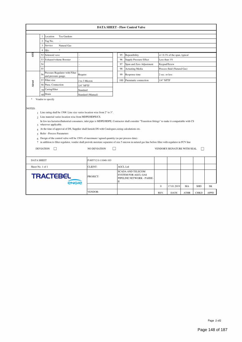
1 Location Tea Gardens
2 Tag No, -
3 Natural Gas
4 Qty. *
DATA SHEET - Flow Control Valve
Service
52 Solenoid vave - 95 Repeatibility +/- 0.1% of the span, typical
53 Exhaust/volume Booster - 96 Supply Pressure Effect Less than 1%
54 - 97 Span and Zero Adjustment Keypad/Screw
55 98 Actuating Media Process fluid (Natural Gas)
56 Require 99 Response time 2 sec. or less
57 2 to 3 Micron 100 Pneumatic connection 1/4" NPTF
58 1/4" NPTF
59 Standard
60 Drain Standard (Manual)
* Vendor to specify
NOTES:
1 Line rating shall be 150#. Line size varies location wise from 2" to 3".
2
3
4
5
6 Design of the control valve will be 150% of maximum / agreed quantity (as per process data).
7 in addition to filter regulator, vendor shall proivde moisture separator of size 5 micron in natural gas line before filter with regulator in FCV line
DEVIATION NO DEVIATION VENDOR'S SIGNATURE WITH SEAL
VENDOR: REV. DATE ATHR CHKD
0 17.01.2019 MA SHD
PROJECT:
SCADA AND TELECOM
SYSTEM FOR AGCL GAS
PIPELINE NETWORK - PAHSE-
II
Sheet No. 1 of 1 CLIENT: AGCL Ltd
Line material varies location wise from MDPE/HDPE/CS.
In few tea factories/Industrial consumers, inlet pipe is MDPE/HDPE, Contractor shall consider "Transition fittings" to make it compatiable with CS
wherever applicable.
At the time of approval of DS, Supplier shall furnish DS with Catalogues,sizing calculations etc.
Refer - Process Parameters
DATA SHEET P.005712-I-11048-103
Air
set
Pressure Regulator with Filter
and pressure gauge.
Filter size
Pneu. Connection
Casing/filter
OT
HE
RS
SK
APPD
Page 2 of2
Page 148 of 187
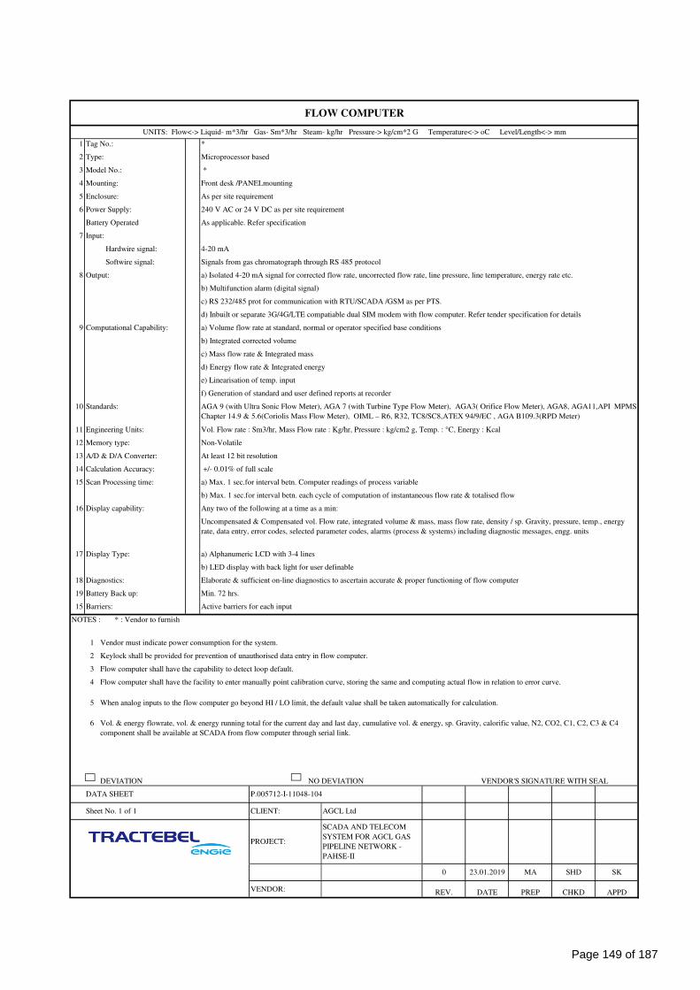
1
2
3
4
5
6
7
8
9
10
11
12
13
14
15
16
17
18
19
15
NOTES : * : Vendor to furnish
1
2
3
4
5
6
DEVIATION NO DEVIATION VENDOR'S SIGNATURE WITH SEAL
APPDVENDOR: REV. DATE PREP CHKD
0 23.01.2019 MA SHD SK
PROJECT:
SCADA AND TELECOM
SYSTEM FOR AGCL GAS
PIPELINE NETWORK -
PAHSE-II
Sheet No. 1 of 1 CLIENT: AGCL Ltd
Flow computer shall have the facility to enter manually point calibration curve, storing the same and computing actual flow in relation to error curve.
When analog inputs to the flow computer go beyond HI / LO limit, the default value shall be taken automatically for calculation.
Vol. & energy flowrate, vol. & energy running total for the current day and last day, cumulative vol. & energy, sp. Gravity, calorific value, N2, CO2, C1, C2, C3 & C4
component shall be available at SCADA from flow computer through serial link.
DATA SHEET P.005712-I-11048-104
Barriers: Active barriers for each input
Vendor must indicate power consumption for the system.
Keylock shall be provided for prevention of unauthorised data entry in flow computer.
Flow computer shall have the capability to detect loop default.
b) LED display with back light for user definable
parametersDiagnostics: Elaborate & sufficient on-line diagnostics to ascertain accurate & proper functioning of flow computer
Battery Back up: Min. 72 hrs.
Display capability: Any two of the following at a time as a min:
Uncompensated & Compensated vol. Flow rate, integrated volume & mass, mass flow rate, density / sp. Gravity, pressure, temp., energy
rate, data entry, error codes, selected parameter codes, alarms (process & systems) including diagnostic messages, engg. units
Display Type: a) Alphanumeric LCD with 3-4 lines
Calculation Accuracy: +/- 0.01% of full scale
Scan Processing time: a) Max. 1 sec.for interval betn. Computer readings of process variable
b) Max. 1 sec.for interval betn. each cycle of computation of instantaneous flow rate & totalised flow
Engineering Units: Vol. Flow rate : Sm3/hr, Mass Flow rate : Kg/hr, Pressure : kg/cm2 g, Temp. : °C, Energy : Kcal
Memory type: Non-Volatile
A/D & D/A Converter: At least 12 bit resolution
e) Linearisation of temp. input
f) Generation of standard and user defined reports at recorder
Standards: AGA 9 (with Ultra Sonic Flow Meter), AGA 7 (with Turbine Type Flow Meter), AGA3( Orifice Flow Meter), AGA8, AGA11,API MPMS
Chapter 14.9 & 5.6(Coriolis Mass Flow Meter), OIML – R6, R32, TC8/SC8,ATEX 94/9/EC , AGA B109.3(RPD Meter)
b) Integrated corrected volume
c) Mass flow rate & Integrated mass
d) Energy flow rate & Integrated energy
b) Multifunction alarm (digital signal)
Computational Capability: a) Volume flow rate at standard, normal or operator specified base conditions
c) RS 232/485 prot for communication with RTU/SCADA /GSM as per PTS.
Hardwire signal: 4-20 mA
Softwire signal: Signals from gas chromatograph through RS 485 protocol
Output: a) Isolated 4-20 mA signal for corrected flow rate, uncorrected flow rate, line pressure, line temperature, energy rate etc.
Mounting: Front desk /PANELmounting
FLOW COMPUTER
d) Inbuilt or separate 3G/4G/LTE compatiable dual SIM modem with flow computer. Refer tender specification for details
As per site requirement
Power Supply: 240 V AC or 24 V DC as per site requirement
Input:
Battery Operated As applicable. Refer specification
UNITS: Flow<-> Liquid- m*3/hr Gas- Sm*3/hr Steam- kg/hr Pressure-> kg/cm*2 G Temperature<-> oC Level/Length<-> mm
Tag No.: *
Type: Microprocessor based
Enclosure:
Model No.: *
Page 149 of 187
UPS SPECIFICATION P.005712
I-11048
105
ASSAM GAS COMPANY LTD SCADA AND TELECOM SYSTEM FOR AGCL GAS PIPELINE
NETWORK - PAHSE-II
TRACTEBEL ENGINEERING PVT. LTD.
UPS SPECIFICATION
RERT
DOC. NO. P.005712-I-11048-105
0 23.01.2019 Release for Procurement MA SHD SK
Rev. Date Subject of revision Prepared By Checked By Approved By
Page 150 of 187
UPS SPECIFICATION P.005712
I-11048
105
Rev-0 AGCL SCADA and Telecom System Project-Phase-II Page 1 of 1
TABLE OF CONTENTS
1.0 SCOPE OF WORK .................................................................................................................. 1
2.0 GENERAL .............................................................................................................................. 1
3.0 AMBIENT CONDITIONS ........................................................................................................ 1
4.0 SPECIFICATION ................................................................................................................... 1
5.0 EARTHING ............................................................................................................................ 2
6.0 PAINTING TYPE & SHADE .................................................................................................... 2
7.0 SPECIFIC REQUIREMENTS ................................................................................................... 2
Σ Σ Σ
Page 151 of 187
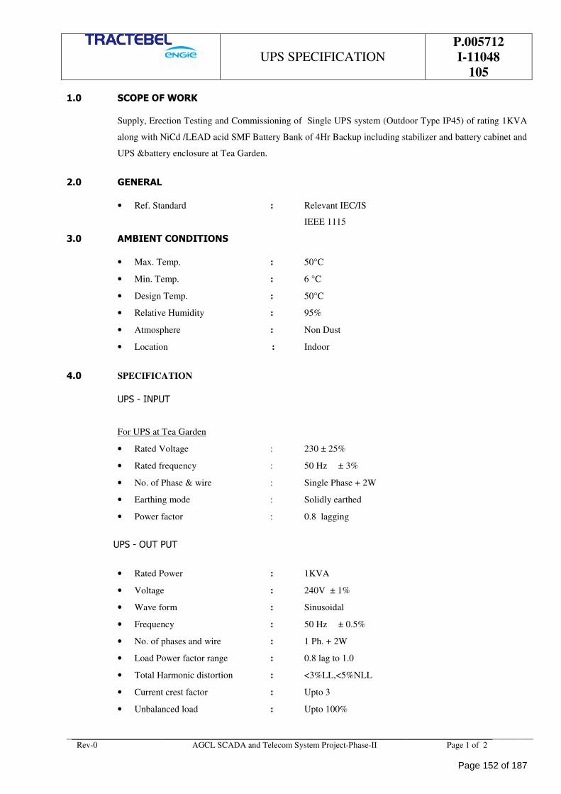
UPS SPECIFICATION P.005712
I-11048
105
Rev-0 AGCL SCADA and Telecom System Project-Phase-II Page 1 of 2
1.0 SCOPE OF WORK
Supply, Erection Testing and Commissioning of Single UPS system (Outdoor Type IP45) of rating 1KVA
along with NiCd /LEAD acid SMF Battery Bank of 4Hr Backup including stabilizer and battery cabinet and
UPS &battery enclosure at Tea Garden.
2.0 GENERAL
• Ref. Standard : Relevant IEC/IS
IEEE 1115
3.0 AMBIENT CONDITIONS
• Max. Temp. : 50°C
• Min. Temp. : 6 °C
• Design Temp. : 50°C
• Relative Humidity : 95%
• Atmosphere : Non Dust
• Location : Indoor
4.0 SPECIFICATION
UPS - INPUT
For UPS at Tea Garden
• Rated Voltage : 230 ± 25%
• Rated frequency : 50 Hz ± 3%
• No. of Phase & wire : Single Phase + 2W
• Earthing mode : Solidly earthed
• Power factor : 0.8 lagging
UPS - OUT PUT
• Rated Power : 1KVA
• Voltage : 240V ± 1%
• Wave form : Sinusoidal
• Frequency : 50 Hz ± 0.5%
• No. of phases and wire : 1 Ph. + 2W
• Load Power factor range : 0.8 lag to 1.0
• Total Harmonic distortion : <3%LL,<5%NLL
• Current crest factor : Upto 3
• Unbalanced load : Upto 100%
Page 152 of 187
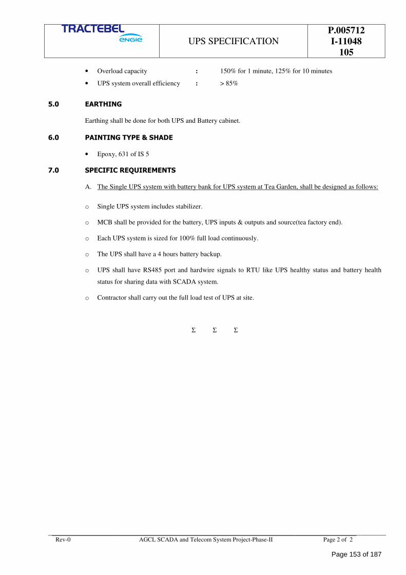
UPS SPECIFICATION P.005712
I-11048
105
Rev-0 AGCL SCADA and Telecom System Project-Phase-II Page 2 of 2
• Overload capacity : 150% for 1 minute, 125% for 10 minutes
• UPS system overall efficiency : > 85%
5.0 EARTHING
Earthing shall be done for both UPS and Battery cabinet.
6.0 PAINTING TYPE & SHADE
• Epoxy, 631 of IS 5
7.0 SPECIFIC REQUIREMENTS
A. The Single UPS system with battery bank for UPS system at Tea Garden, shall be designed as follows:
o Single UPS system includes stabilizer.
o MCB shall be provided for the battery, UPS inputs & outputs and source(tea factory end).
o Each UPS system is sized for 100% full load continuously.
o The UPS shall have a 4 hours battery backup.
o UPS shall have RS485 port and hardwire signals to RTU like UPS healthy status and battery health
status for sharing data with SCADA system.
o Contractor shall carry out the full load test of UPS at site.
Σ Σ Σ
Page 153 of 187
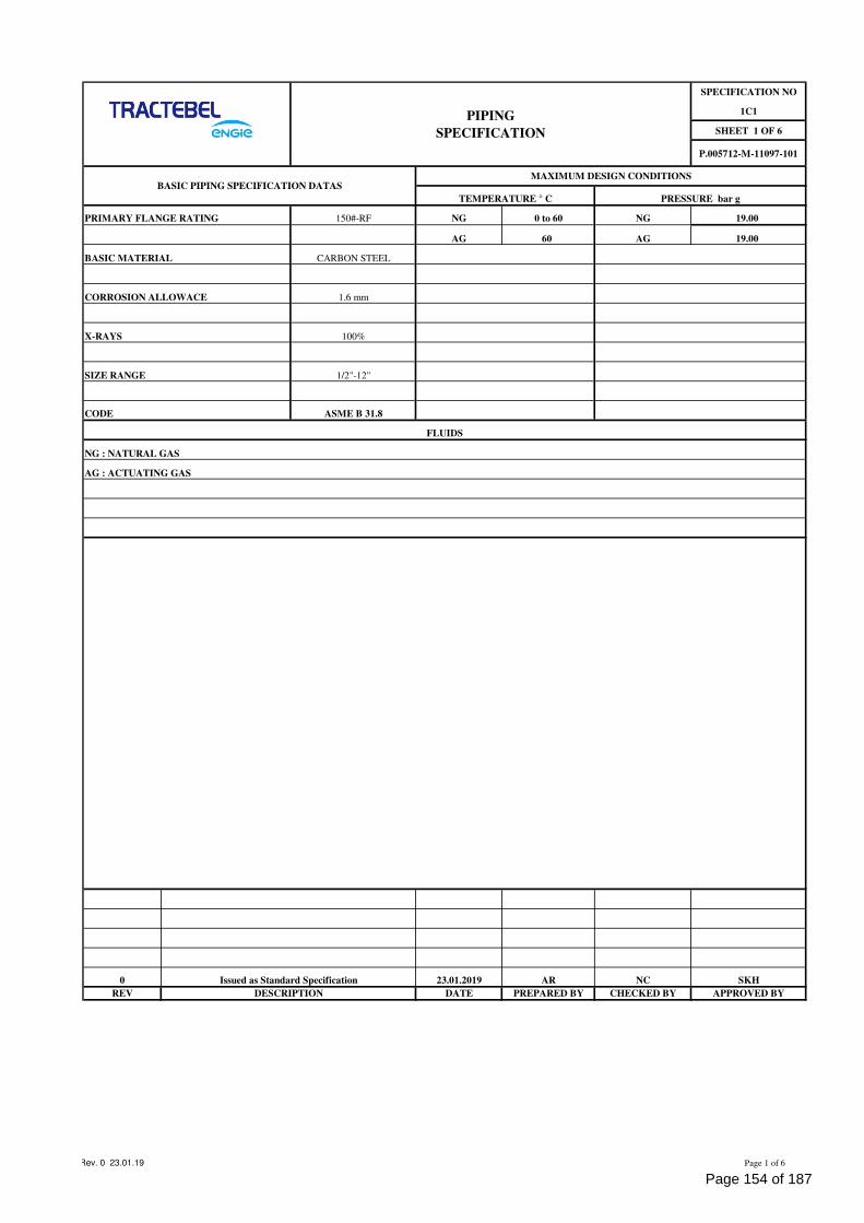
SPECIFICATION NO
1C1
SHEET 1 OF 6
P.005712-M-11097-101
PRIMARY FLANGE RATING 150#-RF NG 0 to 60 NG 19.00
AG 60 AG 19.00
BASIC MATERIAL CARBON STEEL
CORROSION ALLOWACE 1.6 mm
X-RAYS 100%
SIZE RANGE 1/2"-12"
CODE ASME B 31.8
0 23.01.2019 AR NC SKH
REV DATE PREPARED BY CHECKED BY APPROVED BY
FLUIDS
AG : ACTUATING GAS
DESCRIPTION
Issued as Standard Specification
PIPING
SPECIFICATION
BASIC PIPING SPECIFICATION DATAS
NG : NATURAL GAS
MAXIMUM DESIGN CONDITIONS
TEMPERATURE ° C PRESSURE bar g
Rev. 0 23.01.19 Page 1 of 6
Page 154 of 187
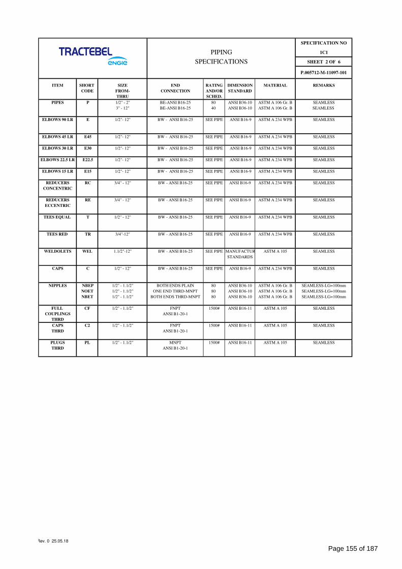
SPECIFICATION NO
1C1
SHEET 2 OF 6
P.005712-M-11097-101
ITEM SHORT SIZE END RATING DIMENSION MATERIAL REMARKS
CODE FROM- CONNECTION AND/OR STANDARD
THRU SCHED.
PIPES P 1/2" - 2" BE-ANSI B16-25 80 ANSI B36-10 ASTM A 106 Gr. B SEAMLESS
3" - 12" BE-ANSI B16-25 40 ANSI B36-10 ASTM A 106 Gr. B SEAMLESS
ELBOWS 90 LR E 1/2"- 12" BW - ANSI B16-25 SEE PIPE ANSI B16-9 ASTM A 234 WPB SEAMLESS
ELBOWS 45 LR E45 1/2"- 12" BW - ANSI B16-25 SEE PIPE ANSI B16-9 ASTM A 234 WPB SEAMLESS
ELBOWS 30 LR E30 1/2"- 12" BW - ANSI B16-25 SEE PIPE ANSI B16-9 ASTM A 234 WPB SEAMLESS
ELBOWS 22.5 LR E22.5 1/2"- 12" BW - ANSI B16-25 SEE PIPE ANSI B16-9 ASTM A 234 WPB SEAMLESS
ELBOWS 15 LR E15 1/2"- 12" BW - ANSI B16-25 SEE PIPE ANSI B16-9 ASTM A 234 WPB SEAMLESS
REDUCERS RC 3/4" - 12" BW - ANSI B16-25 SEE PIPE ANSI B16-9 ASTM A 234 WPB SEAMLESS
CONCENTRIC
REDUCERS RE 3/4" - 12" BW - ANSI B16-25 SEE PIPE ANSI B16-9 ASTM A 234 WPB SEAMLESS
ECCENTRIC
TEES EQUAL T 1/2" - 12" BW - ANSI B16-25 SEE PIPE ANSI B16-9 ASTM A 234 WPB SEAMLESS
TEES RED TR 3/4"-12" BW - ANSI B16-25 SEE PIPE ANSI B16-9 ASTM A 234 WPB SEAMLESS
WELDOLETS WEL 1.1/2"-12" BW - ANSI B16-25 SEE PIPE MANUFACTURER ASTM A 105 SEAMLESS
STANDARDS
CAPS C 1/2" - 12" BW - ANSI B16-25 SEE PIPE ANSI B16-9 ASTM A 234 WPB SEAMLESS
NIPPLES NBEP 1/2" - 1.1/2" BOTH ENDS PLAIN 80 ANSI B36-10 ASTM A 106 Gr. B SEAMLESS-LG=100mm
NOET 1/2" - 1.1/2" ONE END THRD-MNPT 80 ANSI B36-10 ASTM A 106 Gr. B SEAMLESS-LG=100mm
NBET 1/2" - 1.1/2" BOTH ENDS THRD-MNPT 80 ANSI B36-10 ASTM A 106 Gr. B SEAMLESS-LG=100mm
FULL CF 1/2" - 1.1/2" FNPT 1500# ANSI B16-11 ASTM A 105 SEAMLESS
COUPLINGS ANSI B1-20-1
THRD
CAPS C2 1/2" - 1.1/2" FNPT 1500# ANSI B16-11 ASTM A 105 SEAMLESS
THRD ANSI B1-20-1
PLUGS PL 1/2" - 1.1/2" MNPT 1500# ANSI B16-11 ASTM A 105 SEAMLESS
THRD ANSI B1-20-1
PIPING
SPECIFICATIONS
Rev. 0 25.05.18
Page 155 of 187
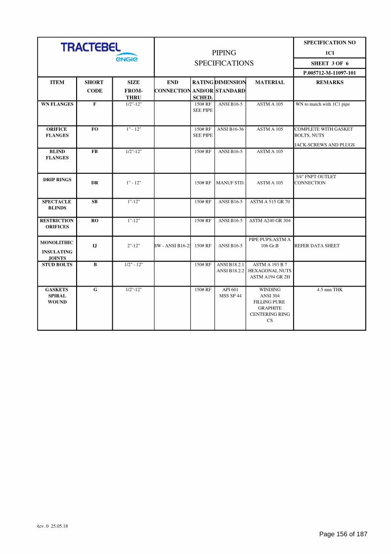
SPECIFICATION NO
1C1
SHEET 3 OF 6
P.005712-M-11097-101
ITEM SHORT SIZE END RATING DIMENSION MATERIAL REMARKS
CODE FROM- CONNECTION AND/OR STANDARD
THRU SCHED.
WN FLANGES F 1/2"-12" 150# RF ANSI B16-5 ASTM A 105 WN to match with 1C1 pipe
SEE PIPE
ORIFICE FO 1" - 12" 150# RF ANSI B16-36 ASTM A 105 COMPLETE WITH GASKET
FLANGES SEE PIPE BOLTS, NUTS
JACK-SCREWS AND PLUGS
BLIND FB 1/2"-12" 150# RF ANSI B16-5 ASTM A 105
FLANGES
DRIP RINGSDR 1" - 12" 150# RF MANUF STD. ASTM A 105
3/4" FNPT OUTLET
CONNECTION
SPECTACLE SB 1"-12" 150# RF ANSI B16-5 ASTM A 515 GR 70
BLINDS
RESTRICTION RO 1"-12" 150# RF ANSI B16-5 ASTM A240 GR 304
ORIFICES
MONOLITHIC IJ 2"-12" BW - ANSI B16-25 150# RF ANSI B16-5
PIPE PUPS:ASTM A
106 Gr.B REFER DATA SHEET
INSULATING
JOINTS
STUD BOLTS B 1/2" - 12" 150# RF ANSI B18.2.1 ASTM A 193 B 7
ANSI B18.2.2 HEXAGONAL NUTS
ASTM A194 GR 2H
GASKETS G 1/2"-12" 150# RF API 601 WINDING 4.5 mm THK
SPIRAL MSS SP 44 ANSI 304
WOUND FILLING PURE
GRAPHITE
CENTERING RING
CS
PIPING
SPECIFICATIONS
Rev. 0 25.05.18
Page 156 of 187
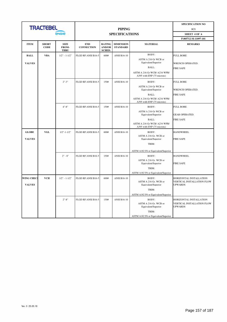
SPECIFICATION NO
1C1
SHEET 4 OF 6
P.005712-M-11097-101
ITEM SHORT SIZE END RATING DIMENSION MATERIAL REMARKS
CODE FROM- CONNECTION AND/OR STANDARD
THRU SCHED.
BALL VBA 1/2" - 1-1/2" FLGD RF:ANSI B16-5 600# ANSI B16-10 BODY: FULL BORE
VALVES
ASTM A 216 Gr WCB or
Equivalent/Superior WRENCH OPERATED.
BALL: FIRE SAFE
ASTM A 216 Gr WCB/ A234 WPB/
A395 with ENP (75 microns)
2"-3" FLGD RF:ANSI B16-5 150# ANSI B16-10 BODY: FULL BORE
ASTM A 216 Gr WCB or
Equivalent/Superior WRENCH OPERATED.
BALL: FIRE SAFE
ASTM A 216 Gr WCB/ A234 WPB/
A395 with ENP (75 microns)
4"-8" FLGD RF:ANSI B16-5 150# ANSI B16-10 BODY: FULL BORE
ASTM A 216 Gr WCB or
Equivalent/Superior GEAR OPERATED.
BALL: FIRE SAFE
ASTM A 216 Gr WCB/ A234 WPB/
A395 with ENP (75 microns)
GLOBE VGL 1/2"-1-1/2" FLGD RF:ANSI B16-5 600# ANSI B16-10 BODY: HANDWHEEL
VALVES
ASTM A 216 Gr. WCB or
Equivalent/Superior FIRE SAFE
TRIM:
ASTM A182 F6 or Equivalent/Superior
2" - 8" FLGD RF:ANSI B16-5 150# ANSI B16-10 BODY: HANDWHEEL
ASTM A 216 Gr. WCB or
Equivalent/Superior FIRE SAFE
TRIM:
ASTM A182 F6 or Equivalent/Superior
SWING CHECK VCH 1/2" - 1-1/2" FLGD RF:ANSI B16-5 600# ANSI B16-10 BODY: HORIZONTAL INSTALLATION
VALVES
ASTM A 216 Gr. WCB or
Equivalent/Superior
VERTICAL INSTALLATION FLOW
UPWARDS
TRIM:
ASTM A182 F6 or Equivalent/Superior
2"-8" FLGD RF:ANSI B16-5 150# ANSI B16-10 BODY: HORIZONTAL INSTALLATION
ASTM A 216 Gr. WCB or
Equivalent/Superior
VERTICAL INSTALLATION FLOW
UPWARDS
TRIM:
ASTM A182 F6 or Equivalent/Superior
PIPING
SPECIFICATIONS
Rev. 0 25.05.18
Page 157 of 187
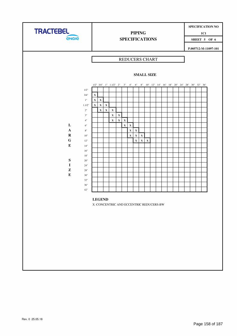
SMALL SIZE
1/2" 3/4" 1" 1.1/2" 2" 3" 4" 6" 8" 10" 12" 14" 16" 18" 20" 24" 28" 30" 32" 36"
1/2"
3/4" X
1" X X
1.1/2" X X X
2" X X X
3" X X
4" X X X
L 6" X X
A 8" X X
R 10" X X X
G 12" X X X
E 14"
16"
18"
S 20"
I 24"
Z 28"
E 30"
32"
36"
42"
LEGEND
X :CONCENTRIC AND ECCENTRIC REDUCERS-BW
REDUCERS CHART
P.005712-M-11097-101
SHEET 5 OF 6
1C1PIPING
SPECIFICATIONS
SPECIFICATION NO
Rev. 0 25.05.18
Page 158 of 187
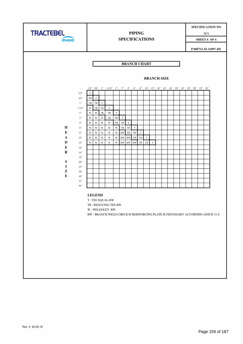
BRANCH SIZE
1/2" 3/4" 1" 1.1/2" 2" 3" 4" 6" 8" 10" 12" 14" 16" 18" 20" 24" 28" 30" 32" 36"
1/2" T
3/4" TR T
1" TR TR T
1.1/2" W TR TR T
2" W W TR TR T
3" W W W TR TR T
4" W W W W TR TR T
H 6" W W W W W TR TR T
E 8" W W W W W BW TR TR T
A 10" W W W W W BW BW TR TR T
D 12" W W W W W BW BW BW TR TR T
E 14"
R 16"
18"
S 20"
I 24"
Z 28"
E 30"
32"
36"
LEGEND
T : TEE EQUAL-BW
TR : REDUCING TEE-BW
W : WELDOLET- BW
BW : BRANCH WELD-CHECK IF REINFORCING PLATE IS NECESSARY ACCORDING ANSI B 31.8
BRANCH CHART
SHEET 6 OF 6
PIPING
SPECIFICATIONS
SPECIFICATION NO
P.005712-M-11097-101
1C1
Rev. 0 25.05.18
Page 159 of 187
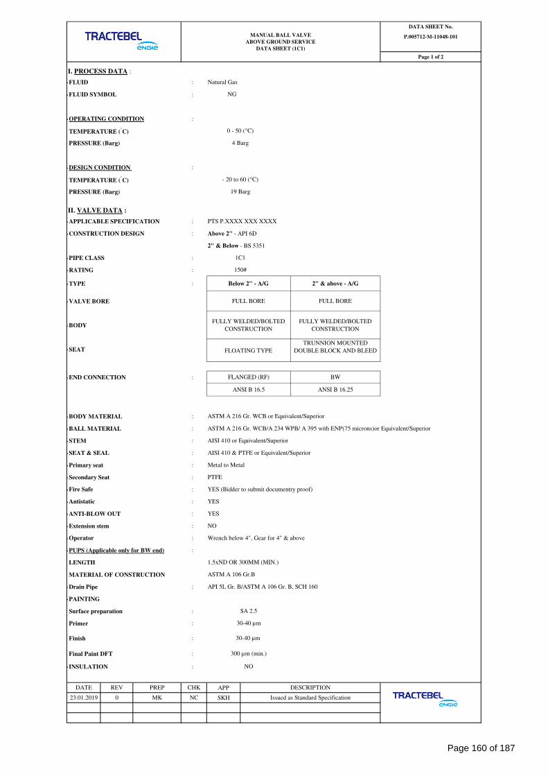
I. PROCESS DATA :
-FLUID : Natural Gas
-FLUID SYMBOL :
-OPERATING CONDITION :
TEMPERATURE (°C)
PRESSURE (Barg)
-DESIGN CONDITION :
TEMPERATURE (°C)
PRESSURE (Barg)
II. VALVE DATA :
-APPLICABLE SPECIFICATION : PTS P.XXXX XXX XXXX
-CONSTRUCTION DESIGN : Above 2" - API 6D
2" & Below - BS 5351
-PIPE CLASS :
-RATING :
-TYPE :
-VALVE BORE
-BODY
-SEAT
-END CONNECTION :
-BODY MATERIAL :
-BALL MATERIAL : ASTM A 216 Gr. WCB/A 234 WPB/ A 395 with ENP(75 microns)or Equivalent/Superior
-STEM : AISI 410 or Equivalent/Superior
-SEAT & SEAL : AISI 410 & PTFE or Equivalent/Superior
-Primary seat : Metal to Metal
-Secondary Seat : PTFE
- : YES (Bidder to submit documentry proof)
- : YES
-ANTI-BLOW OUT : YES
-Extension stem : NO
- : Wrench below 4", Gear for 4" & above
-PUPS (Applicable only for BW end) :
LENGTH
MATERIAL OF CONSTRUCTION
-Drain Pipe : API 5L Gr. B/ASTM A 106 Gr. B, SCH 160
-PAINTING
Surface preparation :
Primer :
Finish :
Final Paint DFT :
-INSULATION :
APP
SKH23.01.2019 Issued as Standard SpecificationMK
ASTM A 106 Gr.B
CHK
NC
30-40 µm
30-40 µm
FULL BOREFULL BORE
1.5xND OR 300MM (MIN.)
SA 2.5
FULLY WELDED/BOLTED
CONSTRUCTION
DATA SHEET No.
P.005712-M-11048-101
Page 1 of 2
4 Barg
MANUAL BALL VALVE
ABOVE GROUND SERVICE
DATA SHEET (1C1)
NG
0 - 50 (°C)
0
ANSI B 16.5
TRUNNION MOUNTED
DOUBLE BLOCK AND BLEED
BW
ANSI B 16.25
300 µm (min.)
ASTM A 216 Gr. WCB or Equivalent/Superior
PREP
- 20 to 60 (°C)
Antistatic
Operator
FLANGED (RF)
19 Barg
Below 2" - A/G
FLOATING TYPE
1C1
DATE REV
Fire Safe
DESCRIPTION
FULLY WELDED/BOLTED
CONSTRUCTION
2" & above - A/G
150#
NO
Page 160 of 187
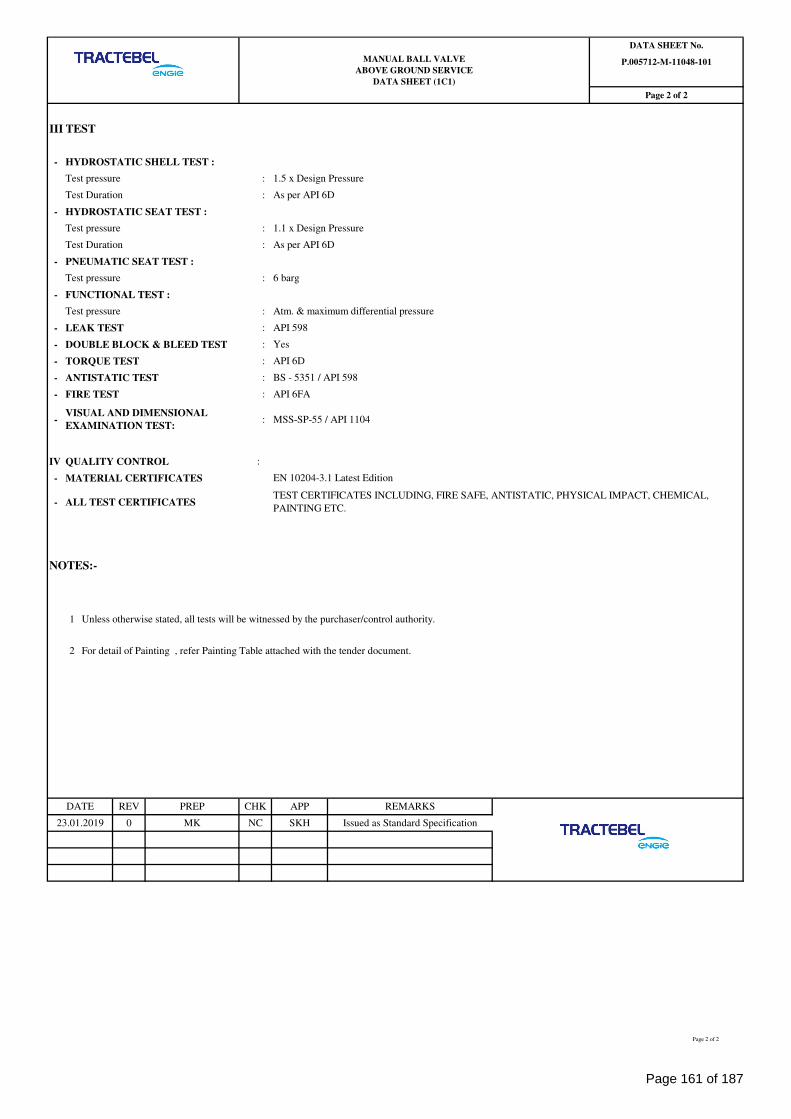
III TEST
- HYDROSTATIC SHELL TEST :
Test pressure : 1.5 x Design Pressure
Test Duration : As per API 6D
- HYDROSTATIC SEAT TEST :
Test pressure : 1.1 x Design Pressure
Test Duration : As per API 6D
- PNEUMATIC SEAT TEST :
Test pressure : 6 barg
- FUNCTIONAL TEST :
Test pressure : Atm. & maximum differential pressure
- LEAK TEST : API 598
- DOUBLE BLOCK & BLEED TEST : Yes
- TORQUE TEST : API 6D
- ANTISTATIC TEST : BS - 5351 / API 598
- FIRE TEST : API 6FA
- : MSS-SP-55 / API 1104
IV QUALITY CONTROL :
- MATERIAL CERTIFICATES EN 10204-3.1 Latest Edition
- ALL TEST CERTIFICATES
NOTES:-
1 Unless otherwise stated, all tests will be witnessed by the purchaser/control authority.
2 For detail of Painting , refer Painting Table attached with the tender document.
23.01.2019 MK Issued as Standard Specification
REMARKSDATE REV
0
PREP
MANUAL BALL VALVE
ABOVE GROUND SERVICE
DATA SHEET (1C1)
CHK APP
NC SKH
TEST CERTIFICATES INCLUDING, FIRE SAFE, ANTISTATIC, PHYSICAL IMPACT, CHEMICAL,
PAINTING ETC.
VISUAL AND DIMENSIONAL
EXAMINATION TEST:
Page 2 of 2
DATA SHEET No.
P.005712-M-11048-101
Page 2 of 2
Page 161 of 187
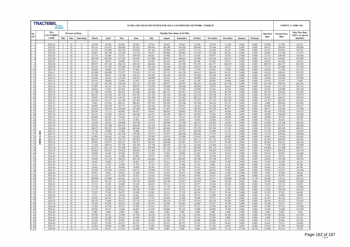
Min Max Operating March April May June July August September October November December January February
1 TEA-01 1 10 4 24.038 30.769 40.385 38.462 34.341 38.462 39.663 41.209 30.769 31.250 0.000 0.000 24.038 41.209 61.813
2 TEA-02 1 10 4 96.154 134.615 200.000 201.923 206.044 180.288 180.288 206.044 153.846 48.077 0.000 0.000 48.077 206.044 309.066
3 TEA-03 1 10 4 41.135 132.908 182.792 195.981 167.462 134.966 145.567 157.132 123.292 36.327 0.000 0.000 36.327 195.981 293.971
4 TEA-04 1 10 4 54.087 105.769 115.385 112.179 110.577 100.962 100.962 115.385 115.385 96.154 0.000 0.000 54.087 115.385 173.077
5 TEA-05 1 10 4 22.774 61.800 51.923 109.978 88.481 85.986 95.173 92.445 90.977 53.024 0.000 0.000 22.774 109.978 164.966
6 TEA-06 1 10 4 168.269 307.692 415.385 416.667 412.088 389.423 408.654 412.088 261.538 144.231 0.000 0.000 144.231 416.667 625.000
7 TEA-07 1 10 4 26.611 49.673 58.096 59.135 65.893 66.526 66.526 86.168 63.865 36.971 0.000 0.000 26.611 86.168 129.251
8 TEA-08 1 10 4 200.971 247.146 368.319 429.439 406.604 350.421 314.550 331.951 461.577 240.635 0.000 0.000 200.971 461.577 692.365
9 TEA-09 1 10 4 96.154 155.769 225.000 187.500 185.440 162.260 162.260 148.352 180.769 72.115 0.000 0.000 72.115 225.000 337.500
10 TEA-10 1 10 4 28.846 50.000 65.385 57.692 54.945 60.096 67.308 71.429 38.462 33.654 0.000 0.000 28.846 71.429 107.143
11 TEA-11 1 10 4 103.846 148.000 171.077 174.615 157.143 147.115 161.538 184.615 188.615 94.231 0.000 0.000 94.231 188.615 282.923
12 TEA-12 1 10 4 67.308 88.615 110.769 129.231 142.857 120.192 120.192 145.604 130.769 48.077 0.000 0.000 48.077 145.604 218.407
13 TEA-13 1 10 4 24.038 38.462 115.385 128.205 109.890 96.154 96.154 109.890 38.462 24.038 0.000 0.000 24.038 128.205 192.308
14 TEA-14 1 10 4 20.192 30.000 32.692 51.923 50.549 38.942 25.481 41.758 40.385 29.808 0.000 0.000 20.192 51.923 77.885
15 TEA-15 1 10 4 111.163 181.238 239.400 225.141 242.429 240.971 240.971 308.363 213.662 101.548 0.000 0.000 101.548 308.363 462.544
16 TEA-16 1 10 4 27.885 94.154 121.154 108.974 110.769 103.846 103.846 109.890 76.923 26.442 0.000 0.000 26.442 121.154 181.731
17 TEA-17 1 10 4 38.942 72.692 85.769 86.538 96.429 97.356 97.356 126.099 93.462 45.192 0.000 0.000 38.942 126.099 189.148
18 TEA-18 1 10 4 115.385 138.462 169.231 153.846 236.264 206.731 201.923 215.835 136.292 86.538 0.000 0.000 86.538 236.264 354.396
19 TEA-19 1 10 4 96.154 124.769 167.538 224.359 247.253 216.346 216.346 233.516 230.769 96.154 0.000 0.000 96.154 247.253 370.879
20 TEA-20 1 10 4 78.697 195.738 149.331 116.760 201.956 224.341 223.825 260.313 204.750 167.322 0.000 0.000 78.697 260.313 390.470
21 TEA-21 1 10 4 120.163 112.477 241.300 187.462 220.137 201.894 161.029 172.357 127.315 282.163 0.000 0.000 112.477 282.163 423.245
22 TEA-22 1 10 4 0.000 115.385 269.231 288.462 247.253 228.365 216.346 192.308 96.154 81.731 0.000 0.000 0.000 288.462 432.692
23 TEA-23 1 10 4 28.995 102.438 89.773 112.404 101.022 99.748 95.675 116.527 121.785 93.524 0.000 0.000 28.995 121.785 182.677
24 TEA-24 1 10 4 112.615 128.554 218.646 197.064 182.648 171.837 171.837 196.385 147.785 88.577 0.000 0.000 88.577 218.646 327.969
25 TEA-25 1 10 4 40.240 75.115 88.885 89.423 99.643 100.601 100.601 130.302 96.577 46.058 0.000 0.000 40.240 130.302 195.453
26 TEA-26 1 10 4 96.154 115.385 144.231 168.269 144.231 126.202 108.173 103.022 57.692 36.058 0.000 0.000 36.058 168.269 252.404
27 TEA-27 1 10 4 60.096 65.385 76.923 72.115 83.791 72.115 72.115 82.418 25.000 24.038 0.000 0.000 24.038 83.791 125.687
28 TEA-28 1 10 4 39.423 20.192 21.154 25.962 33.654 29.447 38.365 33.654 23.846 19.231 0.000 0.000 19.231 39.423 59.135
29 TEA-29 1 10 4 24.038 38.462 188.846 192.308 178.571 188.849 177.048 186.352 116.812 24.038 0.000 0.000 24.038 192.308 288.462
30 TEA-30 1 10 4 63.918 179.188 166.154 149.638 161.429 182.361 188.344 199.714 237.973 110.014 0.000 0.000 63.918 237.973 356.960
31 TEA-31 1 10 4 108.173 230.192 354.808 403.846 370.879 405.649 382.933 271.978 247.500 97.356 0.000 0.000 97.356 405.649 608.474
32 TEA-32 1 10 4 33.750 63.000 73.308 75.000 83.571 84.375 84.375 109.286 81.000 41.731 0.000 0.000 33.750 109.286 163.929
33 TEA-33 1 10 4 72.115 111.538 161.538 176.282 178.571 173.077 180.288 206.044 173.077 72.115 0.000 0.000 72.115 206.044 309.066
34 TEA-34 1 10 4 61.904 105.662 117.562 124.824 133.907 120.524 119.606 136.442 94.485 46.803 0.000 0.000 46.803 136.442 204.663
35 TEA-35 1 10 4 208.423 156.300 276.723 285.962 269.865 246.466 247.385 282.714 237.719 123.851 0.000 0.000 123.851 285.962 428.942
36 TEA-36 1 10 4 86.904 190.677 205.431 190.327 196.187 169.668 167.841 159.374 141.677 94.308 0.000 0.000 86.904 205.431 308.146
37 TEA-37 1 10 4 77.938 109.073 157.338 129.340 123.769 108.495 121.716 138.206 137.858 117.313 0.000 0.000 77.938 157.338 236.008
38 TEA-38 1 10 4 222.072 291.119 313.008 308.917 305.995 267.745 267.745 305.995 291.119 178.803 0.000 0.000 178.803 313.008 469.512
39 TEA-39 1 10 4 99.264 159.027 210.842 198.699 212.964 211.224 211.224 269.832 198.835 93.615 0.000 0.000 93.615 269.832 404.749
40 TEA-41 1 10 4 28.846 43.462 50.385 69.872 55.220 37.981 36.058 61.264 61.538 24.615 0.000 0.000 24.615 69.872 104.808
41 TEA-42 1 10 4 17.115 26.423 31.808 35.962 39.533 32.981 33.173 37.692 28.769 14.423 0.000 0.000 14.423 39.533 59.299
42 TEA-43 1 10 4 38.942 151.154 164.615 205.128 206.044 173.317 166.587 219.780 211.538 90.577 0.000 0.000 38.942 219.780 329.670
43 TEA-44 1 10 4 18.462 19.692 27.077 26.667 26.374 29.231 30.769 26.374 19.692 15.385 0.000 0.000 15.385 30.769 46.154
44 TEA-45 1 10 4 9.231 11.077 11.692 11.795 12.747 13.077 13.846 13.187 9.846 6.154 0.000 0.000 6.154 13.846 20.769
45 TEA-46 1 10 4 18.462 44.231 38.000 36.859 28.264 25.337 28.168 29.151 24.615 25.481 0.000 0.000 18.462 44.231 66.346
46 TEA-47 1 10 4 43.269 115.385 119.615 144.231 125.824 71.875 63.702 117.857 96.154 15.865 0.000 0.000 15.865 144.231 216.346
47 TEA-48 1 10 4 26.971 9.962 38.923 22.468 23.819 35.625 30.673 39.368 28.962 15.962 0.000 0.000 9.962 39.368 59.052
48 TEA-49 1 10 4 14.423 23.077 42.308 44.872 53.434 49.760 49.760 56.593 34.927 24.947 0.000 0.000 14.423 56.593 84.890
49 TEA-50 1 10 4 100.806 125.000 80.645 83.333 80.645 110.887 135.417 131.048 135.417 120.968 28.306 31.339 28.306 135.417 203.125
50 TEA-51 1 10 4 46.154 86.154 110.769 124.359 140.659 130.769 123.077 105.495 73.846 30.769 0.000 0.000 30.769 140.659 210.989
51 TEA-52 1 10 4 21.731 11.692 43.808 35.128 48.434 49.111 54.712 50.577 29.346 18.510 0.000 0.000 11.692 54.712 82.067
52 TEA-53 1 10 4 37.740 41.615 88.577 52.981 39.341 31.178 39.255 35.714 21.000 13.413 0.000 0.000 13.413 88.577 132.865
53 TEA-54 1 10 4 33.173 72.692 96.923 130.769 57.967 49.519 46.154 96.429 86.154 11.082 0.000 0.000 11.082 130.769 196.154
54 TEA-55 1 10 4 31.923 37.962 56.077 42.500 43.462 39.111 37.139 48.516 57.923 35.144 0.000 0.000 31.923 57.923 86.885
55 TEA-56 1 10 4 9.231 14.769 19.692 26.667 29.011 23.077 25.385 26.374 32.000 12.308 0.000 0.000 9.231 32.000 48.000
56 TEA-57 1 10 4 36.202 62.192 96.154 64.038 72.335 63.630 72.308 79.286 70.731 31.587 0.000 0.000 31.587 96.154 144.231
57 TEA-58 1 10 4 146.327 75.869 183.277 172.314 142.973 156.159 127.433 142.643 149.254 50.269 0.000 0.000 50.269 183.277 274.915
58 TEA-59 1 10 4 33.269 41.692 46.615 52.308 46.593 42.308 39.904 43.846 55.077 36.346 0.000 0.000 33.269 55.077 82.615
59 TEA-60 1 10 4 15.385 61.538 49.231 51.282 87.912 69.231 69.231 79.121 61.538 46.154 0.000 0.000 15.385 87.912 131.868
60 TEA-61 1 10 4 30.769 49.231 73.846 66.667 61.538 60.000 56.154 72.088 64.000 15.385 0.000 0.000 15.385 73.846 110.769
61 TEA-62 1 10 4 5.000 5.000 5.000 5.000 5.000 5.000 5.000 5.000 5.000 5.000 5.000 5.000 5.000 5.000 7.500
62 TEA-63 1 10 4 30.769 49.231 73.846 61.538 70.330 61.538 61.538 70.330 98.462 30.769 0.000 0.000 30.769 98.462 147.692
63 TEA-64 1 10 4 18.269 22.308 36.923 42.949 42.308 37.019 37.019 29.121 25.385 4.808 0.000 0.000 4.808 42.949 64.423
64 TEA-65 1 10 4 67.240 53.792 67.881 67.240 67.698 67.240 67.721 67.698 66.600 51.231 0.000 0.000 51.231 67.881 101.821
65 TEA-66 1 10 4 34.615 55.385 69.231 69.231 79.121 69.231 69.231 79.121 55.385 34.615 0.000 0.000 34.615 79.121 118.681
66 TEA-67 1 10 4 33.654 53.846 67.308 67.308 57.692 58.894 54.688 57.692 67.308 42.067 0.000 0.000 33.654 67.308 100.962
67 TEA-68 1 10 4 27.218 28.125 27.218 25.000 0.000 0.000 0.000 0.000 25.000 27.218 27.218 30.134 25.000 30.134 45.201
Normal Flow
Rate
DIB
RU
GA
RH
SCADA AND TELECOM SYSTEM FOR AGCL GAS PIPELINE NETWORK - PAHSE-II P.005712 -I -11000 -101
SL.
NO
TEA
FACTORIES
CODE
Monthly Flow Rates in SCM/hrPressure in Barg Min Flow
Rate
Max Flow Rate
(150% of Agreed
Quantity)
1 of 5
Page 162 of 187
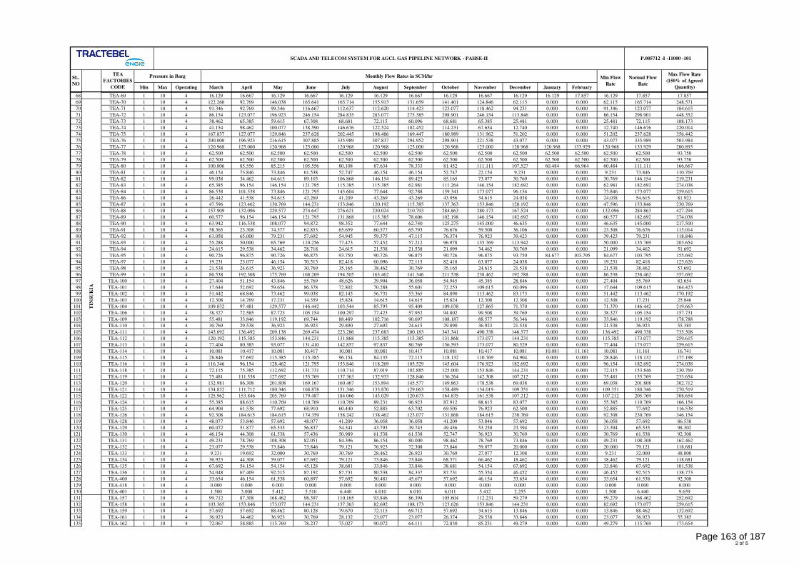
Min Max Operating March April May June July August September October November December January February
Normal Flow
Rate
SCADA AND TELECOM SYSTEM FOR AGCL GAS PIPELINE NETWORK - PAHSE-II P.005712 -I -11000 -101
SL.
NO
TEA
FACTORIES
CODE
Monthly Flow Rates in SCM/hrPressure in Barg Min Flow
Rate
Max Flow Rate
(150% of Agreed
Quantity)
68 TEA-69 1 10 4 16.129 16.667 16.129 16.667 16.129 16.129 16.667 16.129 16.667 16.129 16.129 17.857 16.129 17.857 17.857
69 TEA-70 1 10 4 122.260 92.769 146.038 165.641 165.714 155.913 131.659 141.401 124.846 62.115 0.000 0.000 62.115 165.714 248.571
70 TEA-71 1 10 4 91.346 92.769 99.346 116.667 112.637 112.620 114.423 123.077 118.462 94.231 0.000 0.000 91.346 123.077 184.615
71 TEA-72 1 10 4 86.154 123.077 196.923 246.154 284.835 283.077 275.385 298.901 246.154 113.846 0.000 0.000 86.154 298.901 448.352
72 TEA-73 1 10 4 38.462 65.385 59.615 67.308 68.681 72.115 60.096 68.681 65.385 25.481 0.000 0.000 25.481 72.115 108.173
73 TEA-74 1 10 4 41.154 98.462 100.077 138.590 146.676 122.524 102.452 114.231 67.654 12.740 0.000 0.000 12.740 146.676 220.014
74 TEA-75 1 10 4 167.837 127.077 129.846 237.628 202.445 198.486 169.447 180.989 131.962 51.202 0.000 0.000 51.202 237.628 356.442
75 TEA-76 1 10 4 200.000 196.923 216.615 307.885 335.989 307.837 294.952 298.901 221.538 43.077 0.000 0.000 43.077 335.989 503.984
76 TEA-77 1 10 4 120.968 125.000 120.968 125.000 120.968 120.968 125.000 120.968 125.000 120.968 120.968 133.929 120.968 133.929 200.893
77 TEA-78 1 10 4 62.500 62.500 62.500 62.500 62.500 62.500 62.500 62.500 62.500 62.500 62.500 62.500 62.500 62.500 93.750
78 TEA-79 1 10 4 62.500 62.500 62.500 62.500 62.500 62.500 62.500 62.500 62.500 62.500 62.500 62.500 62.500 62.500 93.750
79 TEA-80 1 10 4 100.806 85.556 85.215 105.556 80.108 87.634 78.333 81.452 111.111 107.527 60.484 66.964 60.484 111.111 166.667
80 TEA-81 1 10 4 46.154 73.846 73.846 61.538 52.747 46.154 46.154 52.747 22.154 9.231 0.000 0.000 9.231 73.846 110.769
81 TEA-82 1 10 4 99.038 34.462 64.615 89.103 106.868 146.154 89.423 85.165 73.077 30.769 0.000 0.000 30.769 146.154 219.231
82 TEA-83 1 10 4 65.385 96.154 146.154 121.795 115.385 115.385 62.981 111.264 146.154 182.692 0.000 0.000 62.981 182.692 274.038
83 TEA-84 1 10 4 86.538 101.538 73.846 121.795 145.604 77.644 92.788 159.341 173.077 96.154 0.000 0.000 73.846 173.077 259.615
84 TEA-86 1 10 4 26.442 41.538 54.615 43.269 41.209 43.269 43.269 43.956 34.615 24.038 0.000 0.000 24.038 54.615 81.923
85 TEA-87 1 10 4 47.596 123.462 130.769 144.231 153.846 120.192 115.385 137.363 153.846 120.192 0.000 0.000 47.596 153.846 230.769
86 TEA-88 1 10 4 157.909 132.096 229.577 274.647 276.621 230.024 210.793 284.863 280.173 167.524 0.000 0.000 132.096 284.863 427.294
87 TEA-89 1 10 4 60.577 96.154 146.154 121.795 131.868 115.385 78.606 102.198 146.154 182.692 0.000 0.000 60.577 182.692 274.038
88 TEA-90 1 10 4 63.942 116.538 108.077 94.872 98.352 77.644 62.740 125.275 145.000 46.635 0.000 0.000 46.635 145.000 217.500
89 TEA-91 1 10 4 58.365 23.308 74.577 62.853 65.659 60.577 65.793 76.676 59.500 36.106 0.000 0.000 23.308 76.676 115.014
90 TEA-92 1 10 4 61.058 65.000 79.231 57.692 54.945 59.375 47.115 76.374 76.923 39.423 0.000 0.000 39.423 79.231 118.846
91 TEA-93 1 10 4 55.288 50.000 65.769 110.256 77.473 57.452 57.212 96.978 135.769 113.942 0.000 0.000 50.000 135.769 203.654
92 TEA-94 1 10 4 24.615 29.538 34.462 28.718 24.615 21.538 21.538 21.099 34.462 30.769 0.000 0.000 21.099 34.462 51.692
93 TEA-95 1 10 4 90.726 96.875 90.726 96.875 93.750 90.726 96.875 90.726 96.875 93.750 84.677 103.795 84.677 103.795 155.692
94 TEA-97 1 10 4 19.231 23.077 46.154 70.513 82.418 60.096 72.115 82.418 63.077 24.038 0.000 0.000 19.231 82.418 123.626
95 TEA-98 1 10 4 21.538 24.615 36.923 30.769 35.165 38.462 30.769 35.165 24.615 21.538 0.000 0.000 21.538 38.462 57.692
96 TEA-99 1 10 4 86.538 192.308 175.769 168.269 194.505 163.462 141.346 211.538 238.462 192.788 0.000 0.000 86.538 238.462 357.692
97 TEA-100 1 10 4 27.404 51.154 43.846 55.769 48.626 39.904 36.058 54.945 45.385 28.846 0.000 0.000 27.404 55.769 83.654
98 TEA-101 1 10 4 17.644 52.692 59.654 86.378 72.802 70.288 55.601 72.253 109.615 60.096 0.000 0.000 17.644 109.615 164.423
99 TEA-102 1 10 4 51.442 68.846 73.462 99.038 82.143 56.731 53.365 84.890 113.462 83.173 0.000 0.000 51.442 113.462 170.192
100 TEA-103 1 10 4 12.308 14.769 17.231 14.359 15.824 14.615 14.615 15.824 12.308 12.308 0.000 0.000 12.308 17.231 25.846
101 TEA-104 1 10 4 109.832 97.481 129.577 146.442 103.544 85.793 95.409 109.038 127.865 71.370 0.000 0.000 71.370 146.442 219.663
102 TEA-106 1 10 4 38.327 72.585 87.723 105.154 100.297 77.423 57.952 94.802 99.508 39.769 0.000 0.000 38.327 105.154 157.731
103 TEA-109 1 10 4 55.481 33.846 119.192 69.744 88.489 102.716 90.697 108.187 88.577 56.346 0.000 0.000 33.846 119.192 178.788
104 TEA-110 1 10 4 30.769 29.538 36.923 36.923 29.890 27.692 24.615 29.890 36.923 21.538 0.000 0.000 21.538 36.923 55.385
105 TEA-111 1 10 4 143.692 136.492 209.138 269.474 223.286 237.683 200.183 343.341 490.338 146.577 0.000 0.000 136.492 490.338 735.508
106 TEA-112 1 10 4 120.192 115.385 153.846 144.231 131.868 115.385 115.385 131.868 173.077 144.231 0.000 0.000 115.385 173.077 259.615
107 TEA-113 1 10 4 77.404 80.385 93.077 131.410 142.857 97.837 80.769 156.593 173.077 80.529 0.000 0.000 77.404 173.077 259.615
108 TEA-114 1 10 4 10.081 10.417 10.081 10.417 10.081 10.081 10.417 10.081 10.417 10.081 10.081 11.161 10.081 11.161 16.741
109 TEA-115 1 10 4 28.846 57.692 115.385 115.385 96.154 84.135 72.115 118.132 110.769 64.904 0.000 0.000 28.846 118.132 177.198
110 TEA-116 1 10 4 116.346 96.154 128.462 121.795 153.846 118.269 105.529 145.604 176.923 182.692 0.000 0.000 96.154 182.692 274.038
111 TEA-118 1 10 4 72.115 75.385 112.692 131.731 110.714 87.019 102.885 125.000 153.846 144.231 0.000 0.000 72.115 153.846 230.769
112 TEA-119 1 10 4 75.481 111.538 127.692 155.769 137.363 132.933 128.846 136.264 142.308 107.212 0.000 0.000 75.481 155.769 233.654
113 TEA-120 1 10 4 132.981 86.308 201.808 169.167 160.467 153.894 145.577 149.863 178.538 69.038 0.000 0.000 69.038 201.808 302.712
114 TEA-121 1 10 4 134.832 111.712 180.346 168.878 151.346 133.870 129.063 158.489 134.019 109.351 0.000 0.000 109.351 180.346 270.519
115 TEA-122 1 10 4 125.962 153.846 205.769 179.487 184.066 143.029 120.673 164.835 161.538 107.212 0.000 0.000 107.212 205.769 308.654
116 TEA-124 1 10 4 55.385 88.615 110.769 110.769 110.769 89.231 96.923 87.912 88.615 83.077 0.000 0.000 55.385 110.769 166.154
117 TEA-125 1 10 4 64.904 61.538 77.692 68.910 60.440 52.885 63.702 69.505 76.923 62.500 0.000 0.000 52.885 77.692 116.538
118 TEA-126 1 10 4 92.308 184.615 184.615 174.359 158.242 138.462 123.077 131.868 184.615 230.769 0.000 0.000 92.308 230.769 346.154
119 TEA-128 1 10 4 48.077 53.846 57.692 48.077 41.209 36.058 36.058 41.209 53.846 57.692 0.000 0.000 36.058 57.692 86.538
120 TEA-129 1 10 4 60.072 51.877 65.535 56.837 54.341 43.793 39.743 49.456 53.250 23.394 0.000 0.000 23.394 65.535 98.302
121 TEA-130 1 10 4 46.154 44.308 61.538 57.436 50.989 61.538 61.538 52.747 36.923 30.769 0.000 0.000 30.769 61.538 92.308
122 TEA-131 1 10 4 49.231 78.769 108.308 82.051 84.396 86.154 80.000 98.462 78.769 73.846 0.000 0.000 49.231 108.308 162.462
123 TEA-132 1 10 4 23.077 29.538 73.846 73.846 79.121 76.923 72.308 73.846 59.077 20.000 0.000 0.000 20.000 79.121 118.681
124 TEA-133 1 10 4 9.231 19.692 32.000 30.769 30.769 28.462 26.923 30.769 27.077 12.308 0.000 0.000 9.231 32.000 48.000
125 TEA-134 1 10 4 36.923 44.308 59.077 67.692 79.121 73.846 73.846 68.571 66.462 18.462 0.000 0.000 18.462 79.121 118.681
126 TEA-135 1 10 4 67.692 54.154 54.154 45.128 38.681 33.846 33.846 38.681 54.154 67.692 0.000 0.000 33.846 67.692 101.538
127 TEA-136 1 10 4 54.048 67.469 92.515 87.192 87.731 80.538 84.337 87.731 55.354 46.452 0.000 0.000 46.452 92.515 138.773
128 TEA-400 1 10 4 33.654 46.154 61.538 60.897 57.692 50.481 45.673 57.692 46.154 33.654 0.000 0.000 33.654 61.538 92.308
129 TEA-418 1 10 4 0.000 0.000 0.000 0.000 0.000 0.000 0.000 0.000 0.000 0.000 0.000 0.000 0.000 0.000 0.000
130 TEA-401 1 10 4 1.500 3.008 5.412 5.510 6.440 6.010 6.010 6.011 5.412 2.255 0.000 0.000 1.500 6.440 9.659
131 TEA-157 1 10 4 99.712 87.308 168.462 98.397 110.165 93.846 86.394 105.604 112.231 59.279 0.000 0.000 59.279 168.462 252.692
132 TEA-158 1 10 4 103.365 153.846 173.077 144.231 137.363 82.692 108.173 123.626 153.846 144.231 0.000 0.000 82.692 173.077 259.615
133 TEA-159 1 10 4 57.692 57.692 88.462 80.128 79.670 72.115 69.712 57.692 34.615 13.846 0.000 0.000 13.846 88.462 132.692
134 TEA-161 1 10 4 36.923 34.462 36.923 30.769 28.132 23.077 23.077 26.374 29.538 33.846 0.000 0.000 23.077 36.923 55.385
135 TEA-162 1 10 4 72.067 58.885 115.769 78.237 75.027 90.072 64.111 72.830 85.231 49.279 0.000 0.000 49.279 115.769 173.654
TIN
SU
KIA
2 of 5
Page 163 of 187
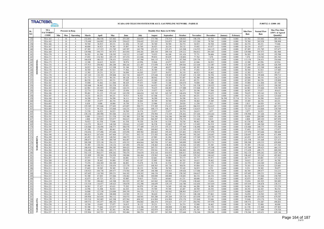
Min Max Operating March April May June July August September October November December January February
Normal Flow
Rate
SCADA AND TELECOM SYSTEM FOR AGCL GAS PIPELINE NETWORK - PAHSE-II P.005712 -I -11000 -101
SL.
NO
TEA
FACTORIES
CODE
Monthly Flow Rates in SCM/hrPressure in Barg Min Flow
Rate
Max Flow Rate
(150% of Agreed
Quantity)
136 TEA-163 1 10 4 232.692 306.538 323.462 253.205 164.835 173.798 174.519 228.022 196.154 63.702 0.000 0.000 63.702 323.462 485.192
137 TEA-165 1 10 4 170.490 184.892 265.938 250.622 258.692 253.183 210.875 205.945 153.200 78.760 0.000 0.000 78.760 265.938 398.908
138 TEA-166 1 10 4 30.769 36.923 49.231 41.026 35.165 30.769 30.769 26.374 36.923 30.769 0.000 0.000 26.374 49.231 73.846
139 TEA-167 1 10 4 40.000 36.923 39.385 35.897 30.769 26.923 26.154 28.132 35.692 43.077 0.000 0.000 26.154 43.077 64.615
140 TEA-168 1 10 4 87.385 117.215 151.785 145.397 142.758 123.471 123.471 143.308 134.523 144.115 0.000 0.000 87.385 151.785 227.677
141 TEA-169 1 10 4 129.986 194.373 307.973 263.054 250.201 209.310 209.310 239.212 304.812 291.043 0.000 0.000 129.986 307.973 461.960
142 TEA-170 1 10 4 56.202 81.500 128.392 118.212 113.687 74.933 84.188 101.434 75.731 58.606 0.000 0.000 56.202 128.392 192.588
143 TEA-171 1 10 4 27.692 134.362 105.119 107.474 121.846 99.832 85.639 118.602 77.762 7.476 0.000 0.000 7.476 134.362 201.542
144 TEA-172 1 10 4 166.038 180.523 236.431 218.821 187.560 164.115 174.212 187.560 229.754 113.154 0.000 0.000 113.154 236.431 354.646
145 TEA-173 1 10 4 12.308 24.615 36.923 38.974 43.956 33.846 43.077 36.923 41.846 36.923 0.000 0.000 12.308 43.956 65.934
146 TEA-174 1 10 4 157.913 258.062 284.200 268.244 221.407 173.058 178.587 209.044 223.446 121.087 0.000 0.000 121.087 284.200 426.300
147 TEA-175 1 10 4 36.923 54.615 112.308 91.346 72.802 27.404 48.077 51.648 65.385 52.404 0.000 0.000 27.404 112.308 168.462
148 TEA-176 1 10 4 30.769 65.385 91.923 77.564 61.813 30.769 37.500 41.758 37.692 35.577 0.000 0.000 30.769 91.923 137.885
149 TEA-177 1 10 4 15.385 29.231 29.231 56.090 44.505 23.077 56.971 56.319 46.923 18.462 0.000 0.000 15.385 56.971 85.457
150 TEA-178 1 10 4 167.163 110.192 199.808 163.718 168.077 125.048 129.087 135.687 131.269 58.558 0.000 0.000 58.558 199.808 299.712
151 TEA-179 1 10 4 81.731 73.077 96.154 80.128 82.418 88.942 79.327 93.407 92.308 28.846 0.000 0.000 28.846 96.154 144.231
152 TEA-180 1 10 4 86.538 69.231 69.231 57.692 49.451 43.269 43.269 49.451 69.231 76.923 0.000 0.000 43.269 86.538 129.808
153 TEA-181 1 10 4 35.000 74.462 111.846 88.429 97.033 74.087 72.188 104.670 70.000 35.288 0.000 0.000 35.000 111.846 167.769
154 TEA-182 1 10 4 103.846 98.462 101.538 82.051 73.626 64.423 65.385 74.725 101.538 126.923 0.000 0.000 64.423 126.923 190.385
155 TEA-183 1 10 4 62.981 101.923 153.846 144.231 111.813 70.433 104.087 137.088 153.846 67.308 0.000 0.000 62.981 153.846 230.769
156 TEA-185 1 10 4 22.774 25.904 32.077 25.936 22.574 33.077 16.507 26.277 20.196 17.500 0.000 0.000 16.507 33.077 49.615
157 TEA-186 1 10 4 99.481 91.123 159.162 142.250 146.654 142.745 142.745 146.654 79.585 70.635 0.000 0.000 70.635 159.162 238.742
158 TEA-187 1 10 4 19.231 69.231 69.231 70.513 76.923 67.308 72.115 82.418 69.231 19.231 0.000 0.000 19.231 82.418 123.626
159 TEA-188 1 10 4 36.290 36.111 36.290 36.111 36.290 36.290 36.111 36.290 36.111 36.290 36.290 35.714 35.714 36.290 54.435
160 TEA-402 1 10 4 15.385 23.077 46.154 38.462 38.462 30.769 30.769 29.670 38.462 15.385 0.000 0.000 15.385 46.154 69.231
161 TEA-403 1 10 4 8.438 9.000 18.000 18.750 25.714 23.906 25.313 28.929 11.250 2.813 0.000 0.000 2.813 28.929 43.393
162 TEA-404 1 10 4 155.385 353.846 377.692 435.897 398.571 375.385 374.327 444.835 366.923 234.615 0.000 0.000 155.385 444.835 667.253
163 TEA-405 1 10 4 72.115 96.154 153.846 144.231 123.626 108.173 108.173 109.890 134.615 72.115 0.000 0.000 72.115 153.846 230.769
164 TEA-189 1 10 4 21.538 36.923 36.923 30.769 26.374 23.077 23.077 26.374 24.615 3.077 0.000 0.000 3.077 36.923 55.385
165 TEA-190 1 10 4 238.154 200.908 301.046 214.333 216.407 156.904 172.529 236.462 327.446 218.442 0.000 0.000 156.904 327.446 491.169
166 TEA-191 1 10 4 0.000 134.615 211.538 192.308 219.780 216.346 216.346 260.989 211.538 0.000 0.000 0.000 0.000 260.989 391.484
167 TEA-192 1 10 4 4.808 207.692 323.077 384.615 405.220 366.587 342.548 376.374 313.462 9.615 0.000 0.000 4.808 405.220 607.830
168 TEA-193 1 10 4 76.923 61.538 73.846 61.538 70.330 61.538 61.538 70.330 98.462 92.308 0.000 0.000 61.538 98.462 147.692
169 TEA-194 1 10 4 114.231 98.615 148.269 120.641 112.692 96.538 92.885 102.747 115.692 94.519 0.000 0.000 92.885 148.269 222.404
170 TEA-195 1 10 4 124.466 136.496 248.373 206.978 177.409 155.233 155.233 177.409 136.496 124.466 0.000 0.000 124.466 248.373 372.560
171 TEA-196 1 10 4 67.308 57.692 88.462 86.538 98.901 100.962 96.154 115.385 115.385 67.308 0.000 0.000 57.692 115.385 173.077
172 TEA-197 1 10 4 154.034 137.496 253.646 225.058 209.582 202.663 195.452 223.401 158.919 127.976 0.000 0.000 127.976 253.646 380.469
173 TEA-198 1 10 4 365.813 247.650 447.604 277.811 302.135 273.502 262.445 294.992 392.265 218.697 0.000 0.000 218.697 447.604 671.406
174 TEA-199 1 10 4 62.452 139.192 149.542 108.272 110.113 67.983 81.204 107.640 137.269 129.279 0.000 0.000 62.452 149.542 224.313
175 TEA-200 1 10 4 298.077 211.538 280.769 304.487 351.648 324.519 307.692 315.934 211.538 221.154 0.000 0.000 211.538 351.648 527.473
176 TEA-201 1 10 4 209.308 225.138 354.123 439.333 404.044 365.558 317.481 349.099 328.985 223.731 0.000 0.000 209.308 439.333 659.000
177 TEA-202 1 10 4 55.385 118.154 118.154 147.692 158.242 138.462 138.462 116.044 147.692 55.385 0.000 0.000 55.385 158.242 237.363
178 TEA-203 1 10 4 186.010 198.808 294.385 309.423 300.934 265.721 241.683 262.473 229.577 147.548 0.000 0.000 147.548 309.423 464.135
179 TEA-204 1 10 4 234.486 212.204 400.173 288.926 277.871 220.541 231.118 266.882 261.050 173.428 0.000 0.000 173.428 400.173 600.260
180 TEA-205 1 10 4 542.135 564.477 858.262 750.474 736.670 618.144 610.933 646.011 829.862 748.865 0.000 0.000 542.135 858.262 1287.392
181 TEA-206 1 10 4 151.909 199.200 254.958 198.006 184.404 129.962 144.291 224.489 329.242 106.442 0.000 0.000 106.442 329.242 493.863
182 TEA-207 1 10 4 55.971 57.085 77.242 84.881 72.755 63.661 55.969 55.173 44.777 55.971 0.000 0.000 44.777 84.881 127.322
183 TEA-208 1 10 4 43.269 38.462 50.000 57.692 63.187 52.885 50.481 46.703 34.615 38.462 0.000 0.000 34.615 63.187 94.780
184 TEA-209 1 10 4 73.476 104.269 104.269 86.891 74.478 81.538 81.538 93.187 97.869 24.370 0.000 0.000 24.370 104.269 156.404
185 TEA-210 1 10 4 85.486 105.312 150.454 125.378 124.071 108.563 101.726 98.676 93.004 70.101 0.000 0.000 70.101 150.454 225.681
186 TEA-211 1 10 4 27.692 39.385 39.385 32.821 28.132 30.769 30.769 35.165 36.923 9.231 0.000 0.000 9.231 39.385 59.077
187 TEA-213 1 10 4 130.923 104.738 209.477 174.564 167.209 146.308 130.923 149.626 117.046 84.769 0.000 0.000 84.769 209.477 314.215
188 TEA-214 1 10 4 107.692 110.769 209.231 164.103 158.242 146.154 153.846 158.242 184.615 169.231 0.000 0.000 107.692 209.231 313.846
189 TEA-215 1 10 4 92.308 67.692 153.846 138.462 114.286 100.000 100.000 118.681 86.154 46.154 0.000 0.000 46.154 153.846 230.769
190 TEA-217 1 10 4 42.875 85.723 85.723 92.885 79.615 75.031 69.663 61.231 68.600 53.611 0.000 0.000 42.875 92.885 139.327
191 TEA-219 1 10 4 55.769 198.462 142.308 201.923 187.363 163.942 163.942 173.626 138.462 33.654 0.000 0.000 33.654 201.923 302.885
192 TEA-220 1 10 4 133.510 116.077 149.423 158.878 152.390 146.659 129.135 144.780 142.654 107.019 0.000 0.000 107.019 158.878 238.317
193 TEA-221 1 10 4 34.563 57.427 65.631 75.202 84.970 87.166 74.349 102.184 64.200 38.389 0.000 0.000 34.563 102.184 153.276
194 TEA-222 1 10 4 22.596 32.308 56.923 64.103 63.736 55.769 55.769 43.407 40.769 20.192 0.000 0.000 20.192 64.103 96.154
195 TEA-223 1 10 4 54.808 127.538 210.000 209.359 194.132 179.712 169.942 208.901 230.677 133.577 0.000 0.000 54.808 230.677 346.015
196 TEA-224 1 10 4 69.428 54.850 108.800 110.503 95.212 98.620 91.531 95.212 108.108 57.063 0.000 0.000 54.850 110.503 165.755
197 TEA-226 1 10 4 189.904 345.650 384.112 358.974 348.901 305.288 293.269 329.310 453.058 433.707 0.000 0.000 189.904 453.058 679.587
198 TEA-228 1 10 4 193.510 342.885 442.308 452.564 408.242 414.904 414.904 474.176 333.846 53.846 0.000 0.000 53.846 474.176 711.264
199 TEA-229 1 10 4 109.572 191.077 286.192 331.067 294.802 266.474 255.623 237.137 284.592 197.976 0.000 0.000 109.572 331.067 496.601
200 TEA-230 1 10 4 10.769 19.692 27.077 24.615 28.132 29.231 29.231 26.374 32.000 18.462 0.000 0.000 10.769 32.000 48.000
201 TEA-231 1 10 4 92.308 73.846 123.077 102.564 114.286 115.385 100.000 131.868 98.462 61.538 0.000 0.000 61.538 131.868 197.802
202 TEA-232 1 10 4 51.486 61.785 82.381 94.394 117.684 102.974 102.974 102.975 61.785 38.615 0.000 0.000 38.615 117.684 176.526
203 TEA-237 1 10 4 235.904 242.723 419.431 392.484 380.374 282.337 263.500 323.648 176.246 220.308 0.000 0.000 176.246 419.431 629.146
DO
OM
DO
OM
AM
AR
GH
ER
ITA
NA
HA
RK
AT
IA
3 of 5
Page 164 of 187
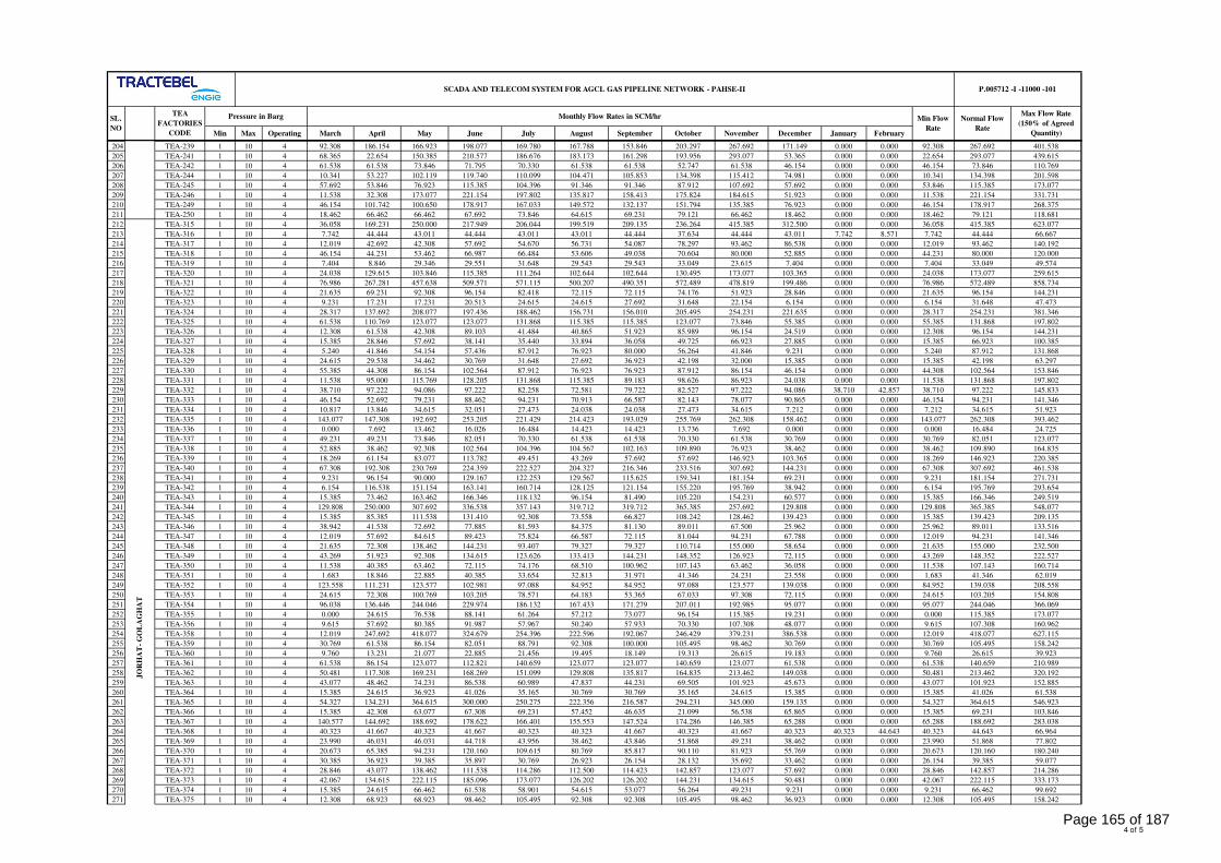
Min Max Operating March April May June July August September October November December January February
Normal Flow
Rate
SCADA AND TELECOM SYSTEM FOR AGCL GAS PIPELINE NETWORK - PAHSE-II P.005712 -I -11000 -101
SL.
NO
TEA
FACTORIES
CODE
Monthly Flow Rates in SCM/hrPressure in Barg Min Flow
Rate
Max Flow Rate
(150% of Agreed
Quantity)
204 TEA-239 1 10 4 92.308 186.154 166.923 198.077 169.780 167.788 153.846 203.297 267.692 171.149 0.000 0.000 92.308 267.692 401.538
205 TEA-241 1 10 4 68.365 22.654 150.385 210.577 186.676 183.173 161.298 193.956 293.077 53.365 0.000 0.000 22.654 293.077 439.615
206 TEA-242 1 10 4 61.538 61.538 73.846 71.795 70.330 61.538 61.538 52.747 61.538 46.154 0.000 0.000 46.154 73.846 110.769
207 TEA-244 1 10 4 10.341 53.227 102.119 119.740 110.099 104.471 105.853 134.398 115.412 74.981 0.000 0.000 10.341 134.398 201.598
208 TEA-245 1 10 4 57.692 53.846 76.923 115.385 104.396 91.346 91.346 87.912 107.692 57.692 0.000 0.000 53.846 115.385 173.077
209 TEA-246 1 10 4 11.538 32.308 173.077 221.154 197.802 135.817 158.413 175.824 184.615 51.923 0.000 0.000 11.538 221.154 331.731
210 TEA-249 1 10 4 46.154 101.742 100.650 178.917 167.033 149.572 132.137 151.794 135.385 76.923 0.000 0.000 46.154 178.917 268.375
211 TEA-250 1 10 4 18.462 66.462 66.462 67.692 73.846 64.615 69.231 79.121 66.462 18.462 0.000 0.000 18.462 79.121 118.681
212 TEA-315 1 10 4 36.058 169.231 250.000 217.949 206.044 199.519 209.135 236.264 415.385 312.500 0.000 0.000 36.058 415.385 623.077
213 TEA-316 1 10 4 7.742 44.444 43.011 44.444 43.011 43.011 44.444 37.634 44.444 43.011 7.742 8.571 7.742 44.444 66.667
214 TEA-317 1 10 4 12.019 42.692 42.308 57.692 54.670 56.731 54.087 78.297 93.462 86.538 0.000 0.000 12.019 93.462 140.192
215 TEA-318 1 10 4 46.154 44.231 53.462 66.987 66.484 53.606 49.038 70.604 80.000 52.885 0.000 0.000 44.231 80.000 120.000
216 TEA-319 1 10 4 7.404 8.846 29.346 29.551 31.648 29.543 29.543 33.049 23.615 7.404 0.000 0.000 7.404 33.049 49.574
217 TEA-320 1 10 4 24.038 129.615 103.846 115.385 111.264 102.644 102.644 130.495 173.077 103.365 0.000 0.000 24.038 173.077 259.615
218 TEA-321 1 10 4 76.986 267.281 457.638 509.571 571.115 500.207 490.351 572.489 478.819 199.486 0.000 0.000 76.986 572.489 858.734
219 TEA-322 1 10 4 21.635 69.231 92.308 96.154 82.418 72.115 72.115 74.176 51.923 28.846 0.000 0.000 21.635 96.154 144.231
220 TEA-323 1 10 4 9.231 17.231 17.231 20.513 24.615 24.615 27.692 31.648 22.154 6.154 0.000 0.000 6.154 31.648 47.473
221 TEA-324 1 10 4 28.317 137.692 208.077 197.436 188.462 156.731 156.010 205.495 254.231 221.635 0.000 0.000 28.317 254.231 381.346
222 TEA-325 1 10 4 61.538 110.769 123.077 123.077 131.868 115.385 115.385 123.077 73.846 55.385 0.000 0.000 55.385 131.868 197.802
223 TEA-326 1 10 4 12.308 61.538 42.308 89.103 41.484 40.865 51.923 85.989 96.154 24.519 0.000 0.000 12.308 96.154 144.231
224 TEA-327 1 10 4 15.385 28.846 57.692 38.141 35.440 33.894 36.058 49.725 66.923 27.885 0.000 0.000 15.385 66.923 100.385
225 TEA-328 1 10 4 5.240 41.846 54.154 57.436 87.912 76.923 80.000 56.264 41.846 9.231 0.000 0.000 5.240 87.912 131.868
226 TEA-329 1 10 4 24.615 29.538 34.462 30.769 31.648 27.692 36.923 42.198 32.000 15.385 0.000 0.000 15.385 42.198 63.297
227 TEA-330 1 10 4 55.385 44.308 86.154 102.564 87.912 76.923 76.923 87.912 86.154 46.154 0.000 0.000 44.308 102.564 153.846
228 TEA-331 1 10 4 11.538 95.000 115.769 128.205 131.868 115.385 89.183 98.626 86.923 24.038 0.000 0.000 11.538 131.868 197.802
229 TEA-332 1 10 4 38.710 97.222 94.086 97.222 82.258 72.581 79.722 82.527 97.222 94.086 38.710 42.857 38.710 97.222 145.833
230 TEA-333 1 10 4 46.154 52.692 79.231 88.462 94.231 70.913 66.587 82.143 78.077 90.865 0.000 0.000 46.154 94.231 141.346
231 TEA-334 1 10 4 10.817 13.846 34.615 32.051 27.473 24.038 24.038 27.473 34.615 7.212 0.000 0.000 7.212 34.615 51.923
232 TEA-335 1 10 4 143.077 147.308 192.692 253.205 221.429 214.423 193.029 255.769 262.308 158.462 0.000 0.000 143.077 262.308 393.462
233 TEA-336 1 10 4 0.000 7.692 13.462 16.026 16.484 14.423 14.423 13.736 7.692 0.000 0.000 0.000 0.000 16.484 24.725
234 TEA-337 1 10 4 49.231 49.231 73.846 82.051 70.330 61.538 61.538 70.330 61.538 30.769 0.000 0.000 30.769 82.051 123.077
235 TEA-338 1 10 4 52.885 38.462 92.308 102.564 104.396 104.567 102.163 109.890 76.923 38.462 0.000 0.000 38.462 109.890 164.835
236 TEA-339 1 10 4 18.269 61.154 83.077 113.782 49.451 43.269 57.692 57.692 146.923 103.365 0.000 0.000 18.269 146.923 220.385
237 TEA-340 1 10 4 67.308 192.308 230.769 224.359 222.527 204.327 216.346 233.516 307.692 144.231 0.000 0.000 67.308 307.692 461.538
238 TEA-341 1 10 4 9.231 96.154 90.000 129.167 122.253 129.567 115.625 159.341 181.154 69.231 0.000 0.000 9.231 181.154 271.731
239 TEA-342 1 10 4 6.154 116.538 151.154 163.141 160.714 128.125 121.154 155.220 195.769 38.942 0.000 0.000 6.154 195.769 293.654
240 TEA-343 1 10 4 15.385 73.462 163.462 166.346 118.132 96.154 81.490 105.220 154.231 60.577 0.000 0.000 15.385 166.346 249.519
241 TEA-344 1 10 4 129.808 250.000 307.692 336.538 357.143 319.712 319.712 365.385 257.692 129.808 0.000 0.000 129.808 365.385 548.077
242 TEA-345 1 10 4 15.385 85.385 111.538 131.410 92.308 73.558 66.827 108.242 128.462 139.423 0.000 0.000 15.385 139.423 209.135
243 TEA-346 1 10 4 38.942 41.538 72.692 77.885 81.593 84.375 81.130 89.011 67.500 25.962 0.000 0.000 25.962 89.011 133.516
244 TEA-347 1 10 4 12.019 57.692 84.615 89.423 75.824 66.587 72.115 81.044 94.231 67.788 0.000 0.000 12.019 94.231 141.346
245 TEA-348 1 10 4 21.635 72.308 138.462 144.231 93.407 79.327 79.327 110.714 155.000 58.654 0.000 0.000 21.635 155.000 232.500
246 TEA-349 1 10 4 43.269 51.923 92.308 134.615 123.626 133.413 144.231 148.352 126.923 72.115 0.000 0.000 43.269 148.352 222.527
247 TEA-350 1 10 4 11.538 40.385 63.462 72.115 74.176 68.510 100.962 107.143 63.462 36.058 0.000 0.000 11.538 107.143 160.714
248 TEA-351 1 10 4 1.683 18.846 22.885 40.385 33.654 32.813 31.971 41.346 24.231 23.558 0.000 0.000 1.683 41.346 62.019
249 TEA-352 1 10 4 123.558 111.231 123.577 102.981 97.088 84.952 84.952 97.088 123.577 139.038 0.000 0.000 84.952 139.038 208.558
250 TEA-353 1 10 4 24.615 72.308 100.769 103.205 78.571 64.183 53.365 67.033 97.308 72.115 0.000 0.000 24.615 103.205 154.808
251 TEA-354 1 10 4 96.038 136.446 244.046 229.974 186.132 167.433 171.279 207.011 192.985 95.077 0.000 0.000 95.077 244.046 366.069
252 TEA-355 1 10 4 0.000 24.615 76.538 88.141 61.264 57.212 73.077 96.154 115.385 19.231 0.000 0.000 0.000 115.385 173.077
253 TEA-356 1 10 4 9.615 57.692 80.385 91.987 57.967 50.240 57.933 70.330 107.308 48.077 0.000 0.000 9.615 107.308 160.962
254 TEA-358 1 10 4 12.019 247.692 418.077 324.679 254.396 222.596 192.067 246.429 379.231 386.538 0.000 0.000 12.019 418.077 627.115
255 TEA-359 1 10 4 30.769 61.538 86.154 82.051 88.791 92.308 100.000 105.495 98.462 30.769 0.000 0.000 30.769 105.495 158.242
256 TEA-360 1 10 4 9.760 13.231 21.077 22.885 21.456 19.495 18.149 19.313 26.615 19.183 0.000 0.000 9.760 26.615 39.923
257 TEA-361 1 10 4 61.538 86.154 123.077 112.821 140.659 123.077 123.077 140.659 123.077 61.538 0.000 0.000 61.538 140.659 210.989
258 TEA-362 1 10 4 50.481 117.308 169.231 168.269 151.099 129.808 135.817 164.835 213.462 149.038 0.000 0.000 50.481 213.462 320.192
259 TEA-363 1 10 4 43.077 48.462 74.231 86.538 60.989 47.837 44.231 69.505 101.923 45.673 0.000 0.000 43.077 101.923 152.885
260 TEA-364 1 10 4 15.385 24.615 36.923 41.026 35.165 30.769 30.769 35.165 24.615 15.385 0.000 0.000 15.385 41.026 61.538
261 TEA-365 1 10 4 54.327 134.231 364.615 300.000 250.275 222.356 216.587 294.231 345.000 159.135 0.000 0.000 54.327 364.615 546.923
262 TEA-366 1 10 4 15.385 42.308 63.077 67.308 69.231 57.452 46.635 21.099 56.538 65.865 0.000 0.000 15.385 69.231 103.846
263 TEA-367 1 10 4 140.577 144.692 188.692 178.622 166.401 155.553 147.524 174.286 146.385 65.288 0.000 0.000 65.288 188.692 283.038
264 TEA-368 1 10 4 40.323 41.667 40.323 41.667 40.323 40.323 41.667 40.323 41.667 40.323 40.323 44.643 40.323 44.643 66.964
265 TEA-369 1 10 4 23.990 46.031 46.031 44.718 43.956 38.462 43.846 51.868 49.231 38.462 0.000 0.000 23.990 51.868 77.802
266 TEA-370 1 10 4 20.673 65.385 94.231 120.160 109.615 80.769 85.817 90.110 81.923 55.769 0.000 0.000 20.673 120.160 180.240
267 TEA-371 1 10 4 30.385 36.923 39.385 35.897 30.769 26.923 26.154 28.132 35.692 33.462 0.000 0.000 26.154 39.385 59.077
268 TEA-372 1 10 4 28.846 43.077 138.462 111.538 114.286 112.500 114.423 142.857 123.077 57.692 0.000 0.000 28.846 142.857 214.286
269 TEA-373 1 10 4 42.067 134.615 222.115 185.096 173.077 126.202 126.202 144.231 134.615 50.481 0.000 0.000 42.067 222.115 333.173
270 TEA-374 1 10 4 15.385 24.615 66.462 61.538 58.901 54.615 53.077 56.264 49.231 9.231 0.000 0.000 9.231 66.462 99.692
271 TEA-375 1 10 4 12.308 68.923 68.923 98.462 105.495 92.308 92.308 105.495 98.462 36.923 0.000 0.000 12.308 105.495 158.242
JO
RH
AT
- G
OL
AG
HA
T
4 of 5
Page 165 of 187
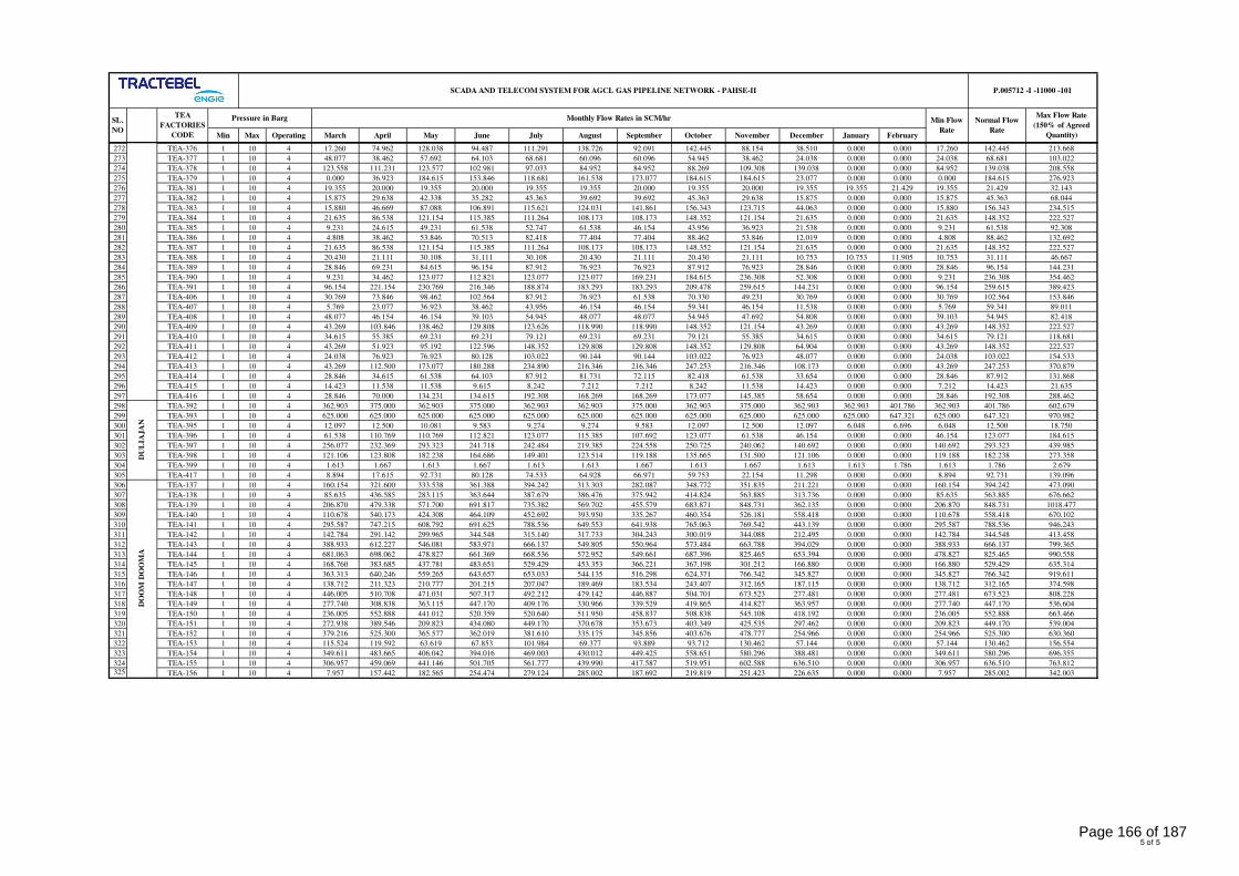
Min Max Operating March April May June July August September October November December January February
Normal Flow
Rate
SCADA AND TELECOM SYSTEM FOR AGCL GAS PIPELINE NETWORK - PAHSE-II P.005712 -I -11000 -101
SL.
NO
TEA
FACTORIES
CODE
Monthly Flow Rates in SCM/hrPressure in Barg Min Flow
Rate
Max Flow Rate
(150% of Agreed
Quantity)
272 TEA-376 1 10 4 17.260 74.962 128.038 94.487 111.291 138.726 92.091 142.445 88.154 38.510 0.000 0.000 17.260 142.445 213.668
273 TEA-377 1 10 4 48.077 38.462 57.692 64.103 68.681 60.096 60.096 54.945 38.462 24.038 0.000 0.000 24.038 68.681 103.022
274 TEA-378 1 10 4 123.558 111.231 123.577 102.981 97.033 84.952 84.952 88.269 109.308 139.038 0.000 0.000 84.952 139.038 208.558
275 TEA-379 1 10 4 0.000 36.923 184.615 153.846 118.681 161.538 173.077 184.615 184.615 23.077 0.000 0.000 0.000 184.615 276.923
276 TEA-381 1 10 4 19.355 20.000 19.355 20.000 19.355 19.355 20.000 19.355 20.000 19.355 19.355 21.429 19.355 21.429 32.143
277 TEA-382 1 10 4 15.875 29.638 42.338 35.282 45.363 39.692 39.692 45.363 29.638 15.875 0.000 0.000 15.875 45.363 68.044
278 TEA-383 1 10 4 15.880 46.669 87.088 106.891 115.621 124.031 141.861 156.343 123.715 44.063 0.000 0.000 15.880 156.343 234.515
279 TEA-384 1 10 4 21.635 86.538 121.154 115.385 111.264 108.173 108.173 148.352 121.154 21.635 0.000 0.000 21.635 148.352 222.527
280 TEA-385 1 10 4 9.231 24.615 49.231 61.538 52.747 61.538 46.154 43.956 36.923 21.538 0.000 0.000 9.231 61.538 92.308
281 TEA-386 1 10 4 4.808 38.462 53.846 70.513 82.418 77.404 77.404 88.462 53.846 12.019 0.000 0.000 4.808 88.462 132.692
282 TEA-387 1 10 4 21.635 86.538 121.154 115.385 111.264 108.173 108.173 148.352 121.154 21.635 0.000 0.000 21.635 148.352 222.527
283 TEA-388 1 10 4 20.430 21.111 30.108 31.111 30.108 20.430 21.111 20.430 21.111 10.753 10.753 11.905 10.753 31.111 46.667
284 TEA-389 1 10 4 28.846 69.231 84.615 96.154 87.912 76.923 76.923 87.912 76.923 28.846 0.000 0.000 28.846 96.154 144.231
285 TEA-390 1 10 4 9.231 34.462 123.077 112.821 123.077 123.077 169.231 184.615 236.308 52.308 0.000 0.000 9.231 236.308 354.462
286 TEA-391 1 10 4 96.154 221.154 230.769 216.346 188.874 183.293 183.293 209.478 259.615 144.231 0.000 0.000 96.154 259.615 389.423
287 TEA-406 1 10 4 30.769 73.846 98.462 102.564 87.912 76.923 61.538 70.330 49.231 30.769 0.000 0.000 30.769 102.564 153.846
288 TEA-407 1 10 4 5.769 23.077 36.923 38.462 43.956 46.154 46.154 59.341 46.154 11.538 0.000 0.000 5.769 59.341 89.011
289 TEA-408 1 10 4 48.077 46.154 46.154 39.103 54.945 48.077 48.077 54.945 47.692 54.808 0.000 0.000 39.103 54.945 82.418
290 TEA-409 1 10 4 43.269 103.846 138.462 129.808 123.626 118.990 118.990 148.352 121.154 43.269 0.000 0.000 43.269 148.352 222.527
291 TEA-410 1 10 4 34.615 55.385 69.231 69.231 79.121 69.231 69.231 79.121 55.385 34.615 0.000 0.000 34.615 79.121 118.681
292 TEA-411 1 10 4 43.269 51.923 95.192 122.596 148.352 129.808 129.808 148.352 129.808 64.904 0.000 0.000 43.269 148.352 222.527
293 TEA-412 1 10 4 24.038 76.923 76.923 80.128 103.022 90.144 90.144 103.022 76.923 48.077 0.000 0.000 24.038 103.022 154.533
294 TEA-413 1 10 4 43.269 112.500 173.077 180.288 234.890 216.346 216.346 247.253 216.346 108.173 0.000 0.000 43.269 247.253 370.879
295 TEA-414 1 10 4 28.846 34.615 61.538 64.103 87.912 81.731 72.115 82.418 61.538 33.654 0.000 0.000 28.846 87.912 131.868
296 TEA-415 1 10 4 14.423 11.538 11.538 9.615 8.242 7.212 7.212 8.242 11.538 14.423 0.000 0.000 7.212 14.423 21.635
297 TEA-416 1 10 4 28.846 70.000 134.231 134.615 192.308 168.269 168.269 173.077 145.385 58.654 0.000 0.000 28.846 192.308 288.462
298 TEA-392 1 10 4 362.903 375.000 362.903 375.000 362.903 362.903 375.000 362.903 375.000 362.903 362.903 401.786 362.903 401.786 602.679
299 TEA-393 1 10 4 625.000 625.000 625.000 625.000 625.000 625.000 625.000 625.000 625.000 625.000 625.000 647.321 625.000 647.321 970.982
300 TEA-395 1 10 4 12.097 12.500 10.081 9.583 9.274 9.274 9.583 12.097 12.500 12.097 6.048 6.696 6.048 12.500 18.750
301 TEA-396 1 10 4 61.538 110.769 110.769 112.821 123.077 115.385 107.692 123.077 61.538 46.154 0.000 0.000 46.154 123.077 184.615
302 TEA-397 1 10 4 256.077 232.369 293.323 241.718 242.484 219.385 224.558 250.725 240.062 140.692 0.000 0.000 140.692 293.323 439.985
303 TEA-398 1 10 4 121.106 123.808 182.238 164.686 149.401 123.514 119.188 135.665 131.500 121.106 0.000 0.000 119.188 182.238 273.358
304 TEA-399 1 10 4 1.613 1.667 1.613 1.667 1.613 1.613 1.667 1.613 1.667 1.613 1.613 1.786 1.613 1.786 2.679
305 TEA-417 1 10 4 8.894 17.615 92.731 80.128 74.533 64.928 66.971 59.753 22.154 11.298 0.000 0.000 8.894 92.731 139.096
306 TEA-137 1 10 4 160.154 321.600 333.538 361.388 394.242 313.303 282.087 348.772 351.835 211.221 0.000 0.000 160.154 394.242 473.090
307 TEA-138 1 10 4 85.635 436.585 283.115 363.644 387.679 386.476 375.942 414.824 563.885 313.736 0.000 0.000 85.635 563.885 676.662
308 TEA-139 1 10 4 206.870 479.338 571.700 691.817 735.382 569.702 455.579 683.871 848.731 362.135 0.000 0.000 206.870 848.731 1018.477
309 TEA-140 1 10 4 110.678 540.173 424.308 464.109 452.692 393.950 335.267 460.354 526.181 558.418 0.000 0.000 110.678 558.418 670.102
310 TEA-141 1 10 4 295.587 747.215 608.792 691.625 788.536 649.553 641.938 765.063 769.542 443.139 0.000 0.000 295.587 788.536 946.243
311 TEA-142 1 10 4 142.784 291.142 299.965 344.548 315.140 317.733 304.243 300.019 344.088 212.495 0.000 0.000 142.784 344.548 413.458
312 TEA-143 1 10 4 388.933 612.227 546.081 583.971 666.137 549.805 550.964 573.484 663.788 394.029 0.000 0.000 388.933 666.137 799.365
313 TEA-144 1 10 4 681.063 698.062 478.827 661.369 668.536 572.952 549.661 687.396 825.465 653.394 0.000 0.000 478.827 825.465 990.558
314 TEA-145 1 10 4 168.760 383.685 437.781 483.651 529.429 453.353 366.221 367.198 301.212 166.880 0.000 0.000 166.880 529.429 635.314
315 TEA-146 1 10 4 363.313 640.246 559.265 643.657 653.033 544.135 516.298 624.371 766.342 345.827 0.000 0.000 345.827 766.342 919.611
316 TEA-147 1 10 4 138.712 211.323 210.777 201.215 207.047 189.469 183.534 243.407 312.165 187.115 0.000 0.000 138.712 312.165 374.598
317 TEA-148 1 10 4 446.005 510.708 471.031 507.317 492.212 479.142 446.887 504.701 673.523 277.481 0.000 0.000 277.481 673.523 808.228
318 TEA-149 1 10 4 277.740 308.838 363.115 447.170 409.176 330.966 339.529 419.865 414.827 363.957 0.000 0.000 277.740 447.170 536.604
319 TEA-150 1 10 4 236.005 552.888 441.012 520.359 520.640 511.950 458.837 508.838 545.108 418.192 0.000 0.000 236.005 552.888 663.466
320 TEA-151 1 10 4 272.938 389.546 209.823 434.080 449.170 370.678 353.673 403.349 425.535 297.462 0.000 0.000 209.823 449.170 539.004
321 TEA-152 1 10 4 379.216 525.300 365.577 362.019 381.610 335.175 345.856 403.676 478.777 254.966 0.000 0.000 254.966 525.300 630.360
322 TEA-153 1 10 4 115.524 119.592 63.619 67.853 101.984 69.377 93.889 93.712 130.462 57.144 0.000 0.000 57.144 130.462 156.554
323 TEA-154 1 10 4 349.611 483.665 406.042 394.016 469.003 430.012 449.425 558.651 580.296 388.481 0.000 0.000 349.611 580.296 696.355
324 TEA-155 1 10 4 306.957 459.069 441.146 501.705 561.777 439.990 417.587 519.951 602.588 636.510 0.000 0.000 306.957 636.510 763.812
325 TEA-156 1 10 4 7.957 157.442 182.565 254.474 279.124 285.002 187.692 219.819 251.423 226.635 0.000 0.000 7.957 285.002 342.003
DU
LIA
JA
ND
OO
M D
OO
MA
5 of 5
Page 166 of 187
CONTROL AND OPERATION
PHILOSOPHY
P.005712
I-11000
102
ASSAM GAS COMPANY LTD
SCADA AND TELECOM SYSTEM FOR AGCL GAS PIPELINE
NETWORK - PAHSE-II
TRACTEBEL ENGINEERING PVT. LTD.
CONTROL AND OPERATION PHILOSOPHYRERT
DOC. NO. P.005712-I-11000-102
0 23.01.2019 Release for Procurement MA SHD SK
Rev. Date Subject of revision Prepared By Checked By Approved By
Page 167 of 187
CONTROL AND OPERATION
PHILOSOPHY
P.005712
I-11000
102
Rev.0 AGCL SCADA and Telecom System Project-Phase-II Page 1 of 1
TABLE OF CONTENTS
1.0 TEA FACTORY ....................................................................................................................... 1
2.0 SCADA PHILOSOPHY ............................................................................................................ 1
3.0 SERVER (SMS/EMAIL/MOBILE) ........................................................................................... 2
4.0 GAS RECONCILIATION ......................................................................................................... 3
Page 168 of 187
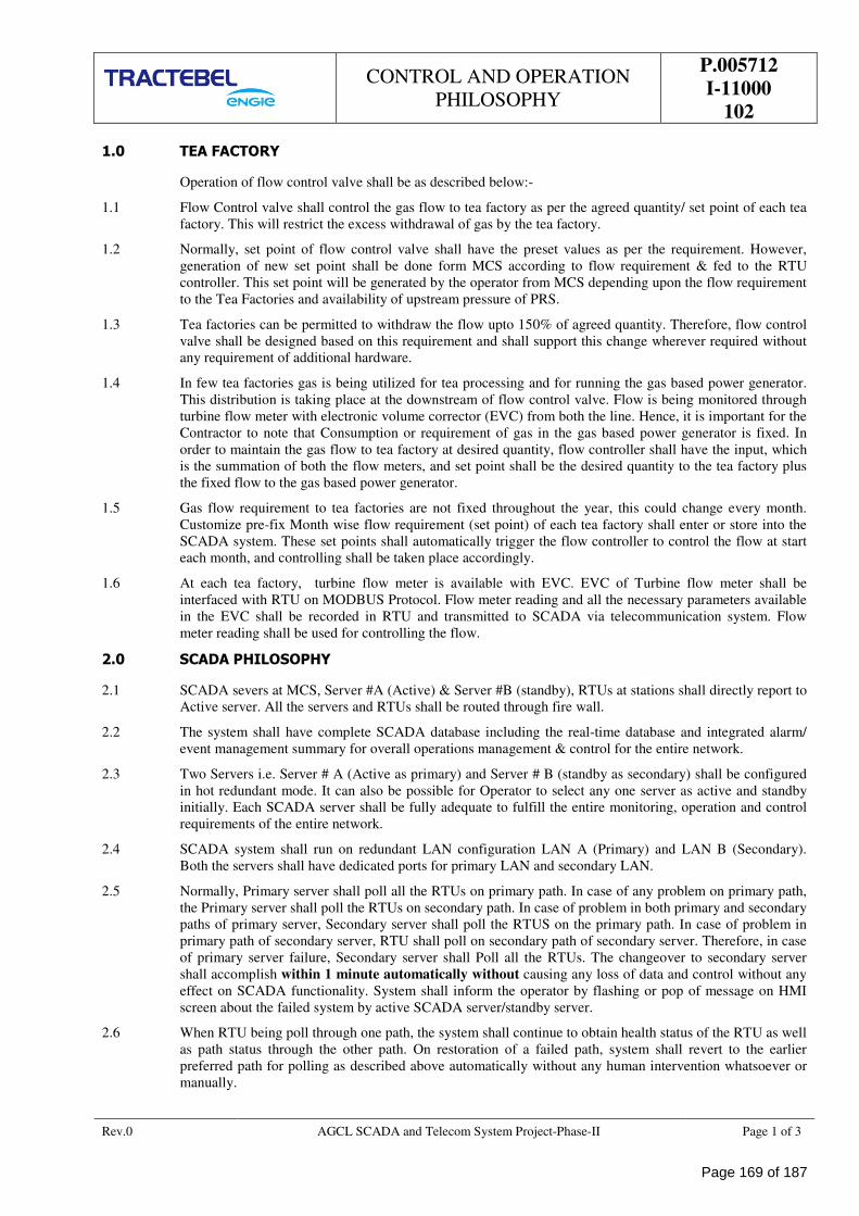
CONTROL AND OPERATION
PHILOSOPHY
P.005712
I-11000
102
Rev.0 AGCL SCADA and Telecom System Project-Phase-II Page 1 of 3
1.0 TEA FACTORY
Operation of flow control valve shall be as described below:-
1.1 Flow Control valve shall control the gas flow to tea factory as per the agreed quantity/ set point of each tea
factory. This will restrict the excess withdrawal of gas by the tea factory.
1.2 Normally, set point of flow control valve shall have the preset values as per the requirement. However,
generation of new set point shall be done form MCS according to flow requirement & fed to the RTU
controller. This set point will be generated by the operator from MCS depending upon the flow requirement
to the Tea Factories and availability of upstream pressure of PRS.
1.3 Tea factories can be permitted to withdraw the flow upto 150% of agreed quantity. Therefore, flow control
valve shall be designed based on this requirement and shall support this change wherever required without
any requirement of additional hardware.
1.4 In few tea factories gas is being utilized for tea processing and for running the gas based power generator.
This distribution is taking place at the downstream of flow control valve. Flow is being monitored through
turbine flow meter with electronic volume corrector (EVC) from both the line. Hence, it is important for the
Contractor to note that Consumption or requirement of gas in the gas based power generator is fixed. In
order to maintain the gas flow to tea factory at desired quantity, flow controller shall have the input, which
is the summation of both the flow meters, and set point shall be the desired quantity to the tea factory plus
the fixed flow to the gas based power generator.
1.5 Gas flow requirement to tea factories are not fixed throughout the year, this could change every month.
Customize pre-fix Month wise flow requirement (set point) of each tea factory shall enter or store into the
SCADA system. These set points shall automatically trigger the flow controller to control the flow at start
each month, and controlling shall be taken place accordingly.
1.6 At each tea factory, turbine flow meter is available with EVC. EVC of Turbine flow meter shall be
interfaced with RTU on MODBUS Protocol. Flow meter reading and all the necessary parameters available
in the EVC shall be recorded in RTU and transmitted to SCADA via telecommunication system. Flow
meter reading shall be used for controlling the flow.
2.0 SCADA PHILOSOPHY
2.1 SCADA severs at MCS, Server #A (Active) & Server #B (standby), RTUs at stations shall directly report to
Active server. All the servers and RTUs shall be routed through fire wall.
2.2 The system shall have complete SCADA database including the real-time database and integrated alarm/
event management summary for overall operations management & control for the entire network.
2.3 Two Servers i.e. Server # A (Active as primary) and Server # B (standby as secondary) shall be configured
in hot redundant mode. It can also be possible for Operator to select any one server as active and standby
initially. Each SCADA server shall be fully adequate to fulfill the entire monitoring, operation and control
requirements of the entire network.
2.4 SCADA system shall run on redundant LAN configuration LAN A (Primary) and LAN B (Secondary).
Both the servers shall have dedicated ports for primary LAN and secondary LAN.
2.5 Normally, Primary server shall poll all the RTUs on primary path. In case of any problem on primary path,
the Primary server shall poll the RTUs on secondary path. In case of problem in both primary and secondary
paths of primary server, Secondary server shall poll the RTUS on the primary path. In case of problem in
primary path of secondary server, RTU shall poll on secondary path of secondary server. Therefore, in case
of primary server failure, Secondary server shall Poll all the RTUs. The changeover to secondary server
shall accomplish within 1 minute automatically without causing any loss of data and control without any
effect on SCADA functionality. System shall inform the operator by flashing or pop of message on HMI
screen about the failed system by active SCADA server/standby server.
2.6 When RTU being poll through one path, the system shall continue to obtain health status of the RTU as well
as path status through the other path. On restoration of a failed path, system shall revert to the earlier
preferred path for polling as described above automatically without any human intervention whatsoever or
manually.
Page 169 of 187
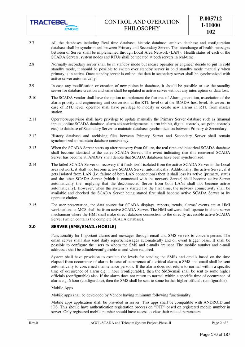
CONTROL AND OPERATION
PHILOSOPHY
P.005712
I-11000
102
Rev.0 AGCL SCADA and Telecom System Project-Phase-II Page 2 of 3
2.7 All the databases including Real time database, historic database, archive database and configuration
database shall be synchronized between Primary and Secondary Server. The interchange of health messages
between of Server shall be implemented through Local Area Network (LAN). Health status of each of the
SCADA Servers, system nodes and RTUs shall be updated at both servers in real-time.
2.8 Normally secondary server shall be in standby mode but incase operator or engineer decide to put in cold
standby mode, it should be possible to switch over standby server in cold standby mode manually when
primary is in active. Once standby server is online, the data in secondary server shall be synchronized with
active server automatically.
2.9 In case any modification or creation of new points in database, it should be possible to use the standby
server for database creation and same shall be updated in active server without any interruption or data loss.
2.10 The SCADA vendor shall have the option to implement the features of Alarm generation, association of the
alarm priority and engineering unit conversion at the RTU level or at the SCADA host level. However, in
case of RTU level, operator shall have privilege to modify or create new alarms in RTU from master
station.
2.11 Operator/supervisor shall have privilege to update manually the Primary Server database such as (manual
inputs, online SCADA database, alarm acknowledgements, alarm inhibit, digital controls, set-point controls
etc.) to database of Secondary Server to maintain database synchronization between Primary & Secondary.
2.12 History database and archiving files between Primary Server and Secondary Server shall remain
synchronized to maintain database consistency.
2.13 When the SCADA Server starts up after recovery from failure, the real time and historical SCADA database
shall become identical to the active SCADA Server. The event indicating that this recovered SCADA
Server has become STANDBY shall denote that SCADA databases have been synchronized.
2.14 The failed SCADA Server on recovery if it finds itself isolated from the active SCADA Server in the Local
area network, it shall not become active SCADA Server automatically. Additionally, the active Server, if it
gets isolated from LAN (i.e. failure of both LAN connections) then it shall loss its active (primary) status
and the other SCADA Server (which is connected with the network Server) shall become active Server
automatically (i.e. implying that the disconnected Server from both LANs shall not become active
automatically). However, when the system is started for the first time, the network connectivity shall be
available and checked the SCADA Server being started first shall become active SCADA Server or by
operator choice.
2.15 For user presentation, the data source for SCADA displays, reports, trends, alarms/ events etc at HMI
workstations at MCS shall be from active SCADA Server. The HMI software shall operate in client-server
mechanism where the HMI shall make direct database connection to the directly accessible active SCADA
Server (which contains the complete SCADA database).
3.0 SERVER (SMS/EMAIL/MOBILE)
Functionality for Important alarms and messages through email and SMS servers to concern person. The
email server shall also send daily reports/messages automatically and on event trigger basis. It shall be
possible to configure the users to whom the SMS and e-mails are sent. The mobile number and e-mail
addresses shall be editable/configurable as and when required.
System shall have provision to escalate the levels for sending the SMSs and emails based on the time
elapsed from occurrence of alarm. In case of occurrence of a critical alarm, a SMS and email shall be sent
automatically to concerned maintenance persons. If the alarm does not return to normal within a specific
time of occurrence of alarm e.g. 1 hour (configurable), then the SMS/email shall be sent to some higher
officials (configurable) also. If the alarm does not return to normal within a specific time of occurrence of
alarm e.g. 6 hour (configurable), then the SMS shall be sent to some further higher officials (configurable).
Mobile Apps
Mobile apps shall be developed by Vendor having minimum following functionality.
Mobile apps application shall be provided in server. This apps shall be compatible with ANDROID and
iOS. This should have authentication registration process on “OTP” based on registered mobile number in
server. Only registered mobile number should have access to view their related parameters.
Page 170 of 187
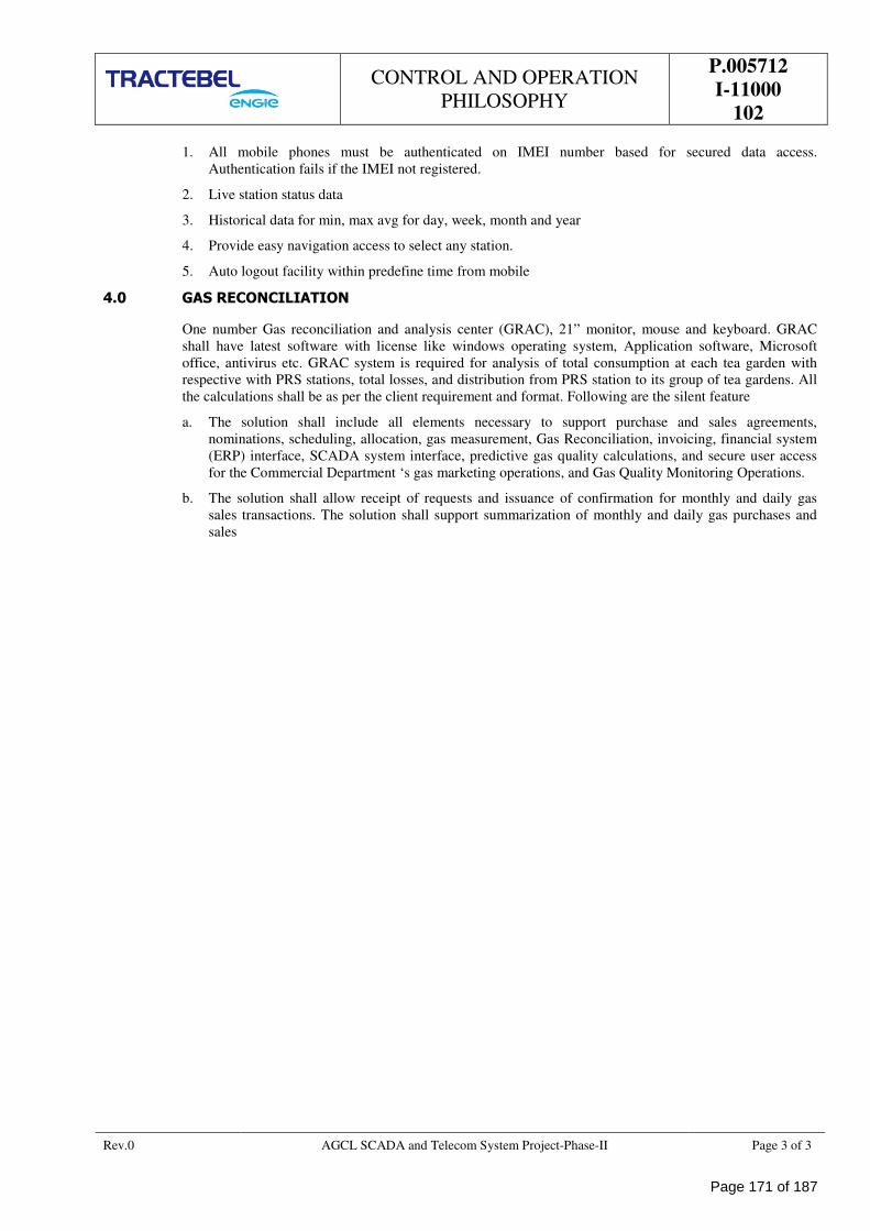
CONTROL AND OPERATION
PHILOSOPHY
P.005712
I-11000
102
Rev.0 AGCL SCADA and Telecom System Project-Phase-II Page 3 of 3
1. All mobile phones must be authenticated on IMEI number based for secured data access.
Authentication fails if the IMEI not registered.
2. Live station status data
3. Historical data for min, max avg for day, week, month and year
4. Provide easy navigation access to select any station.
5. Auto logout facility within predefine time from mobile
4.0 GAS RECONCILIATION
One number Gas reconciliation and analysis center (GRAC), 21” monitor, mouse and keyboard. GRAC
shall have latest software with license like windows operating system, Application software, Microsoft
office, antivirus etc. GRAC system is required for analysis of total consumption at each tea garden with
respective with PRS stations, total losses, and distribution from PRS station to its group of tea gardens. All
the calculations shall be as per the client requirement and format. Following are the silent feature
a. The solution shall include all elements necessary to support purchase and sales agreements,
nominations, scheduling, allocation, gas measurement, Gas Reconciliation, invoicing, financial system
(ERP) interface, SCADA system interface, predictive gas quality calculations, and secure user access
for the Commercial Department ‘s gas marketing operations, and Gas Quality Monitoring Operations.
b. The solution shall allow receipt of requests and issuance of confirmation for monthly and daily gas
sales transactions. The solution shall support summarization of monthly and daily gas purchases and
sales
Page 171 of 187
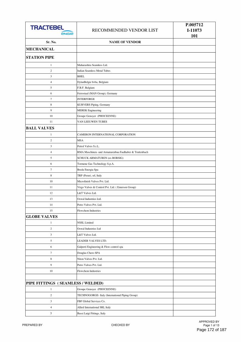
RECOMMENDED VENDOR LIST
P.005712
I-11073
101
Sr. No. NAME OF VENDOR
MECHANICAL
STATION PIPE
1 Maharashtra Seamless Ltd.
2 Indian Seamless Metal Tubes
3 BHEL
4 DylanBelgie bvba, Belgium
5 F.B.F. Belgium
6 Ferrostaal (MAN Group), Germany
7 INTERFORGE
8 KURVERS Piping, Germany
9 MEREK Engineering
10 Groupe Genoyer (PHOCEENNE)
11 VAN LEEUWEN TUBES
BALL VALVES
1 CAMERON INTERNATIONAL CORPORATION
2 MSA
3 Petrol Valves S.r.L.
4 RMA Maschinen- und Armaturenbau Faulhaber & Truttenbach
5 SCHUCK ARMATUREN (ex BORSIG)
6 Tormene Gas Technology S.p.A.
7 Breda Energia Spa
8 TRP (Perar), srl, Italy
10 Microfinish Valves Pvt. Ltd.
11 Virgo Valves & Control Pvt. Ltd. ( Emerson Group)
12 L&T Valves Ltd.
13 Oswal Industries Ltd.
14 Petro Valves Pvt. Ltd.
15 Flowchem Industries
GLOBE VALVES
1 NSSL Limited
2 Oswal Industries Ltd
3 L&T Valves Ltd.
5 LEADER VALVES LTD.
6 Galperti Engineering & Flow control spa
7 Douglas Chero SPA
8 Niton Valves Pvt. Ltd.
9 Petro Valves Pvt. Ltd.
10 Flowchem Industries
PIPE FITTINGS ( SEAMLESS / WELDED)
1 Groupe Genoyer (PHOCEENNE)
2 TECHNOGORGE- Italy (International Piping Group)
3 FBF Global Services Co.
4 Allied International SRL Italy
5 Bassi Luigi Fittings, Italy
PREPARED BY CHECKED BYAPPROVED BY
Page 1 of 13
Page 172 of 187
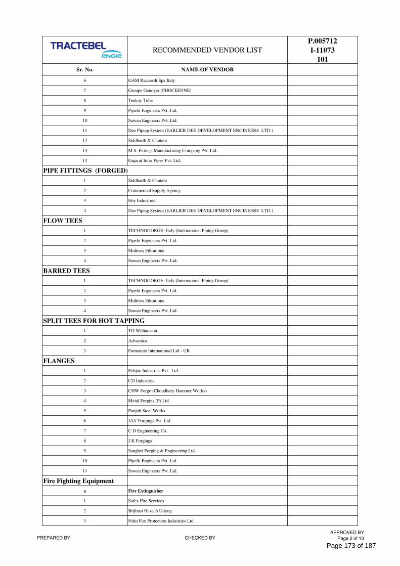
RECOMMENDED VENDOR LIST
P.005712
I-11073
101
Sr. No. NAME OF VENDOR
6 GAM Raccordi Spa Italy
7 Groupe Genoyer (PHOCEENNE)
8 Teekay Tube
9 Pipefit Engineers Pvt. Ltd.
10 Sawan Engineers Pvt. Ltd.
11 Dee Piping System (EARLIER DEE DEVELOPMENT ENGINEERS LTD.)
12 Siddharth & Gautam
13 M.S. Fittings Manufacturing Company Pvt. Ltd.
14 Gujarat Infra Pipes Pvt. Ltd.
PIPE FITTINGS (FORGED)
1 Siddharth & Gautam
2 Commercial Supply Agency
3 Eby Industries
4 Dee Piping System (EARLIER DEE DEVELOPMENT ENGINEERS LTD.)
FLOW TEES
1 TECHNOGORGE- Italy (International Piping Group)
2 Pipefit Engineers Pvt. Ltd.
3 Multitex Filtrations
4 Sawan Engineers Pvt. Ltd.
BARRED TEES
1 TECHNOGORGE- Italy (International Piping Group)
2 Pipefit Engineers Pvt. Ltd.
3 Multitex Filtrations
4 Sawan Engineers Pvt. Ltd.
SPLIT TEES FOR HOT TAPPING
1 TD Williamson
2 Advantica
3 Furmanite International Ltd - UK
FLANGES
1 Echjay Industries Pvt. Ltd.
2 CD Industries
3 CHW Forge (Choudhary Hammer Works)
4 Metal Forgins (P) Ltd.
5 Punjab Steel Works
6 JAV Forgings Pvt. Ltd.
7 C D Engineering Co.
8 J K Forgings
9 Sanghvi Forging & Engineering Ltd.
10 Pipefit Engineers Pvt. Ltd.
11 Sawan Engineers Pvt. Ltd.
Fire Fighting Equipment
a Fire Extinguisher
1 Safex Fire Services
2 Brijbasi Hi-tech Udyog
3 Nitin Fire Protection Industries Ltd.
PREPARED BY CHECKED BYAPPROVED BY
Page 2 of 13
Page 173 of 187
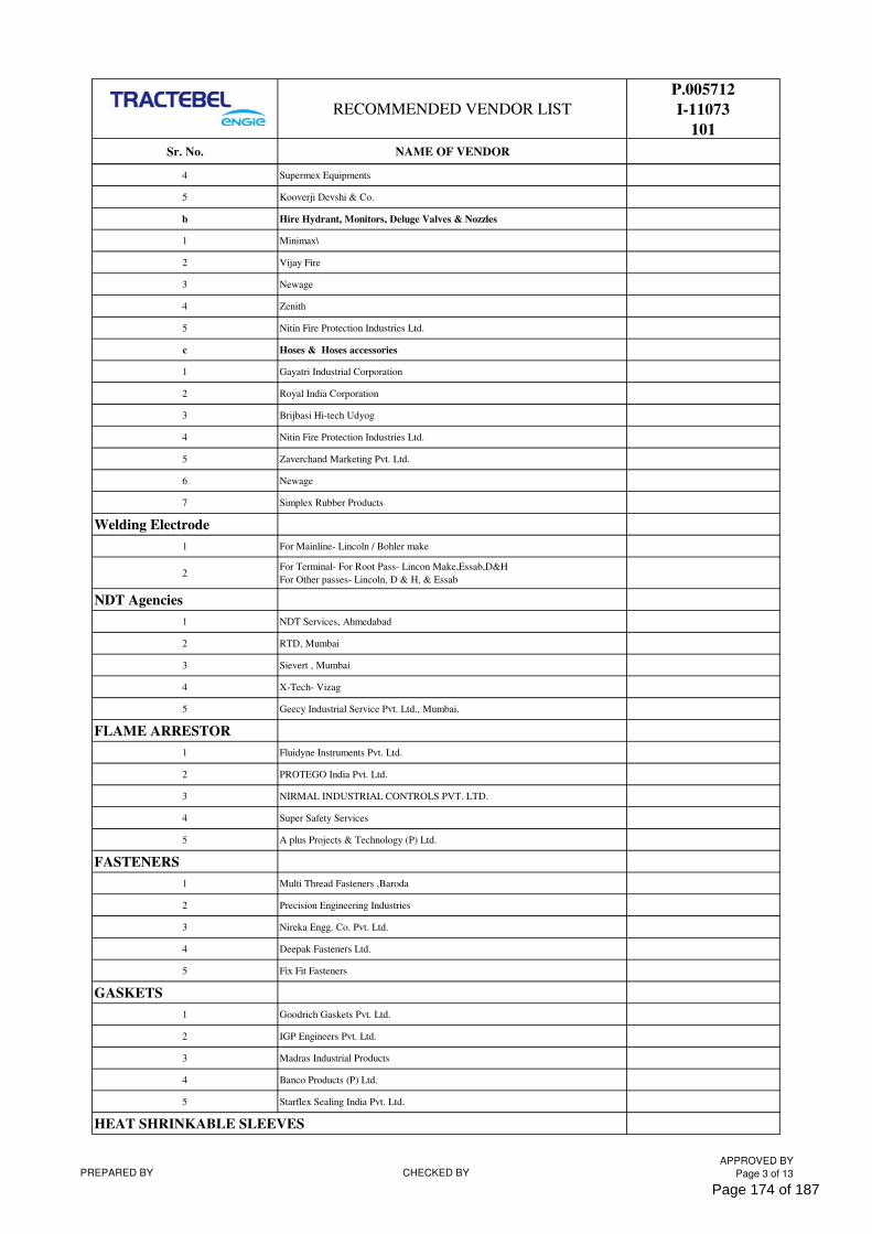
RECOMMENDED VENDOR LIST
P.005712
I-11073
101
Sr. No. NAME OF VENDOR
4 Supermex Equipments
5 Kooverji Devshi & Co.
b Hire Hydrant, Monitors, Deluge Valves & Nozzles
1 Minimax\
2 Vijay Fire
3 Newage
4 Zenith
5 Nitin Fire Protection Industries Ltd.
c Hoses & Hoses accessories
1 Gayatri Industrial Corporation
2 Royal India Corporation
3 Brijbasi Hi-tech Udyog
4 Nitin Fire Protection Industries Ltd.
5 Zaverchand Marketing Pvt. Ltd.
6 Newage
7 Simplex Rubber Products
Welding Electrode
1 For Mainline- Lincoln / Bohler make
2For Terminal- For Root Pass- Lincon Make,Essab,D&H
For Other passes- Lincoln, D & H, & Essab
NDT Agencies
1 NDT Services, Ahmedabad
2 RTD, Mumbai
3 Sievert , Mumbai
4 X-Tech- Vizag
5 Geecy Industrial Service Pvt. Ltd., Mumbai.
FLAME ARRESTOR
1 Fluidyne Instruments Pvt. Ltd.
2 PROTEGO India Pvt. Ltd.
3 NIRMAL INDUSTRIAL CONTROLS PVT. LTD.
4 Super Safety Services
5 A plus Projects & Technology (P) Ltd.
FASTENERS
1 Multi Thread Fasteners ,Baroda
2 Precision Engineering Industries
3 Nireka Engg. Co. Pvt. Ltd.
4 Deepak Fasteners Ltd.
5 Fix Fit Fasteners
GASKETS
1 Goodrich Gaskets Pvt. Ltd.
2 IGP Engineers Pvt. Ltd.
3 Madras Industrial Products
4 Banco Products (P) Ltd.
5 Starflex Sealing India Pvt. Ltd.
HEAT SHRINKABLE SLEEVES
PREPARED BY CHECKED BYAPPROVED BY
Page 3 of 13
Page 174 of 187
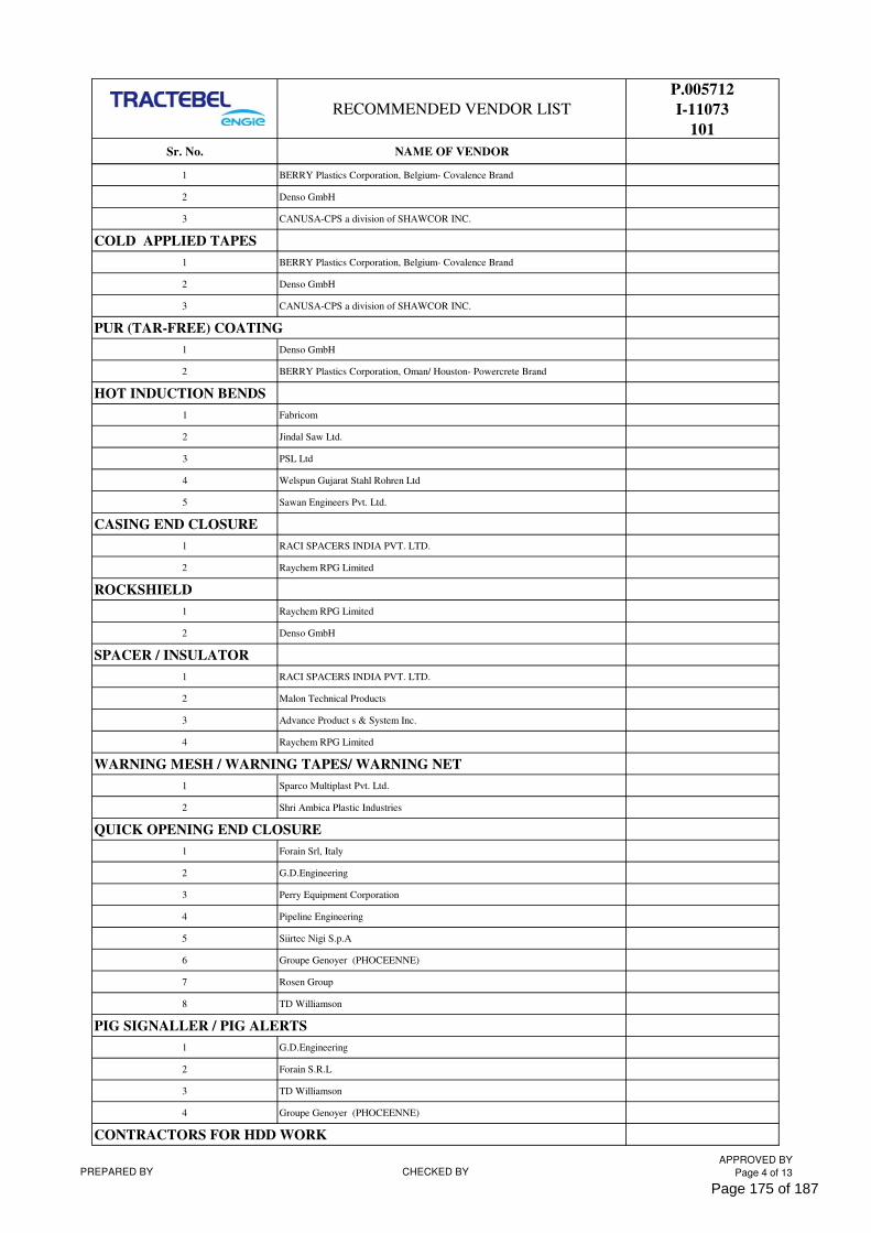
RECOMMENDED VENDOR LIST
P.005712
I-11073
101
Sr. No. NAME OF VENDOR
1 BERRY Plastics Corporation, Belgium- Covalence Brand
2 Denso GmbH
3 CANUSA-CPS a division of SHAWCOR INC.
COLD APPLIED TAPES
1 BERRY Plastics Corporation, Belgium- Covalence Brand
2 Denso GmbH
3 CANUSA-CPS a division of SHAWCOR INC.
PUR (TAR-FREE) COATING
1 Denso GmbH
2 BERRY Plastics Corporation, Oman/ Houston- Powercrete Brand
HOT INDUCTION BENDS
1 Fabricom
2 Jindal Saw Ltd.
3 PSL Ltd
4 Welspun Gujarat Stahl Rohren Ltd
5 Sawan Engineers Pvt. Ltd.
CASING END CLOSURE
1 RACI SPACERS INDIA PVT. LTD.
2 Raychem RPG Limited
ROCKSHIELD
1 Raychem RPG Limited
2 Denso GmbH
SPACER / INSULATOR
1 RACI SPACERS INDIA PVT. LTD.
2 Malon Technical Products
3 Advance Product s & System Inc.
4 Raychem RPG Limited
WARNING MESH / WARNING TAPES/ WARNING NET
1 Sparco Multiplast Pvt. Ltd.
2 Shri Ambica Plastic Industries
QUICK OPENING END CLOSURE
1 Forain Srl, Italy
2 G.D.Engineering
3 Perry Equipment Corporation
4 Pipeline Engineering
5 Siirtec Nigi S.p.A
6 Groupe Genoyer (PHOCEENNE)
7 Rosen Group
8 TD Williamson
PIG SIGNALLER / PIG ALERTS
1 G.D.Engineering
2 Forain S.R.L
3 TD Williamson
4 Groupe Genoyer (PHOCEENNE)
CONTRACTORS FOR HDD WORK
PREPARED BY CHECKED BYAPPROVED BY
Page 4 of 13
Page 175 of 187
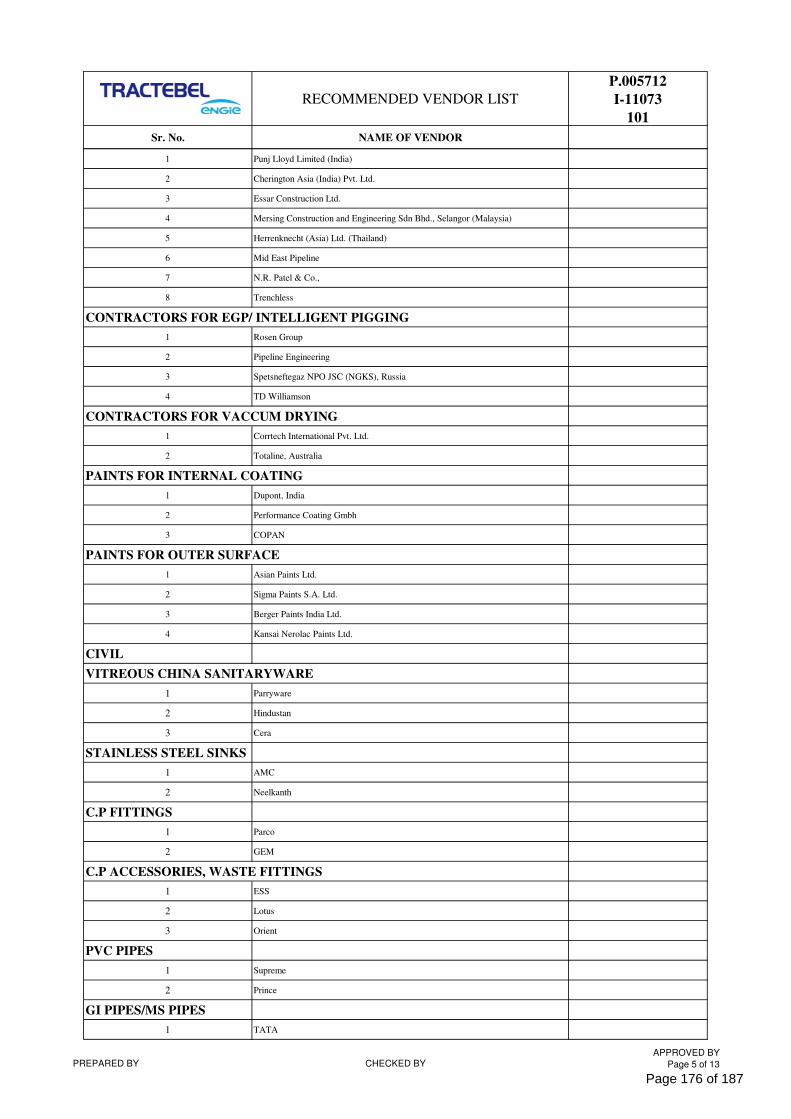
RECOMMENDED VENDOR LIST
P.005712
I-11073
101
Sr. No. NAME OF VENDOR
1 Punj Lloyd Limited (India)
2 Cherington Asia (India) Pvt. Ltd.
3 Essar Construction Ltd.
4 Mersing Construction and Engineering Sdn Bhd., Selangor (Malaysia)
5 Herrenknecht (Asia) Ltd. (Thailand)
6 Mid East Pipeline
7 N.R. Patel & Co.,
8 Trenchless
CONTRACTORS FOR EGP/ INTELLIGENT PIGGING
1 Rosen Group
2 Pipeline Engineering
3 Spetsneftegaz NPO JSC (NGKS), Russia
4 TD Williamson
CONTRACTORS FOR VACCUM DRYING
1 Corrtech International Pvt. Ltd.
2 Totaline, Australia
PAINTS FOR INTERNAL COATING
1 Dupont, India
2 Performance Coating Gmbh
3 COPAN
PAINTS FOR OUTER SURFACE
1 Asian Paints Ltd.
2 Sigma Paints S.A. Ltd.
3 Berger Paints India Ltd.
4 Kansai Nerolac Paints Ltd.
CIVIL
VITREOUS CHINA SANITARYWARE
1 Parryware
2 Hindustan
3 Cera
STAINLESS STEEL SINKS
1 AMC
2 Neelkanth
C.P FITTINGS
1 Parco
2 GEM
C.P ACCESSORIES, WASTE FITTINGS
1 ESS
2 Lotus
3 Orient
PVC PIPES
1 Supreme
2 Prince
GI PIPES/MS PIPES
1 TATA
PREPARED BY CHECKED BYAPPROVED BY
Page 5 of 13
Page 176 of 187
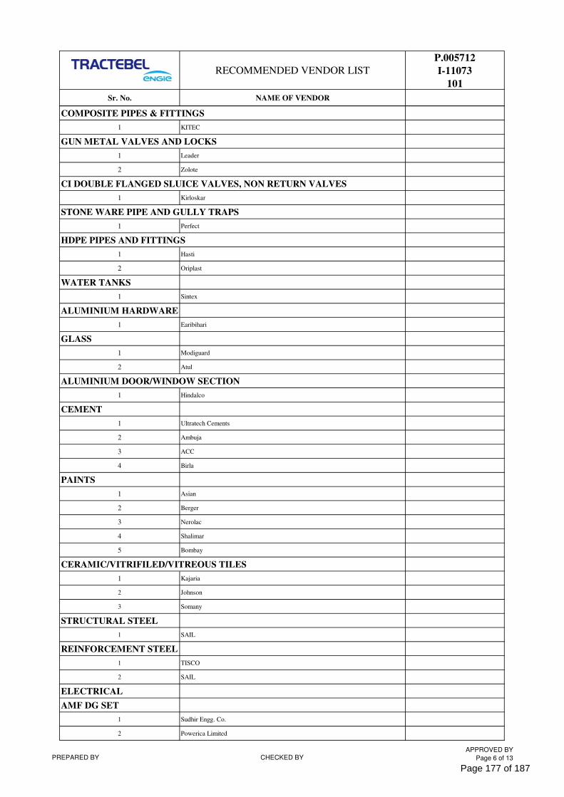
RECOMMENDED VENDOR LIST
P.005712
I-11073
101
Sr. No. NAME OF VENDOR
COMPOSITE PIPES & FITTINGS
1 KITEC
GUN METAL VALVES AND LOCKS
1 Leader
2 Zolote
CI DOUBLE FLANGED SLUICE VALVES, NON RETURN VALVES
1 Kirloskar
STONE WARE PIPE AND GULLY TRAPS
1 Perfect
HDPE PIPES AND FITTINGS
1 Hasti
2 Oriplast
WATER TANKS
1 Sintex
ALUMINIUM HARDWARE
1 Earibihari
GLASS
1 Modiguard
2 Atul
ALUMINIUM DOOR/WINDOW SECTION
1 Hindalco
CEMENT
1 Ultratech Cements
2 Ambuja
3 ACC
4 Birla
PAINTS
1 Asian
2 Berger
3 Nerolac
4 Shalimar
5 Bombay
CERAMIC/VITRIFILED/VITREOUS TILES
1 Kajaria
2 Johnson
3 Somany
STRUCTURAL STEEL
1 SAIL
REINFORCEMENT STEEL
1 TISCO
2 SAIL
ELECTRICAL
AMF DG SET
1 Sudhir Engg. Co.
2 Powerica Limited
PREPARED BY CHECKED BYAPPROVED BY
Page 6 of 13
Page 177 of 187
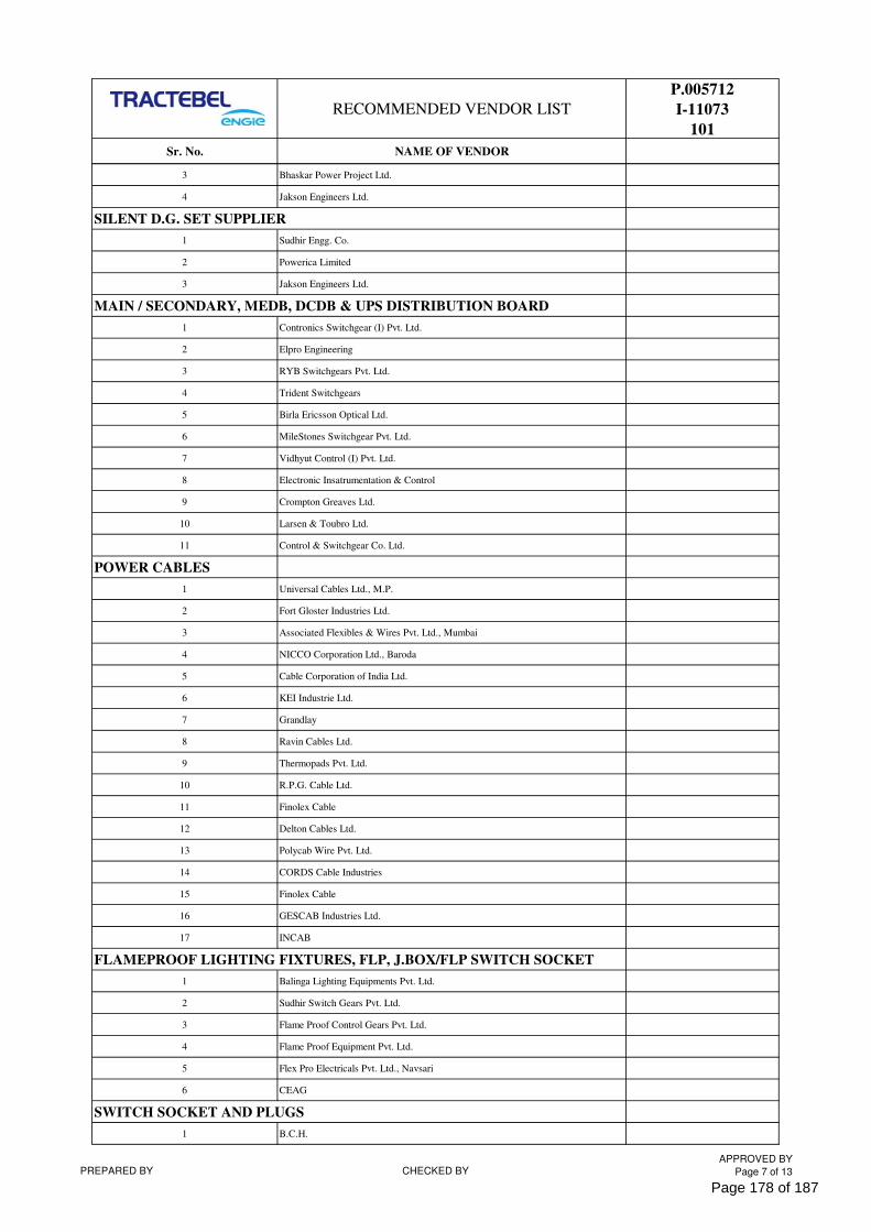
RECOMMENDED VENDOR LIST
P.005712
I-11073
101
Sr. No. NAME OF VENDOR
3 Bhaskar Power Project Ltd.
4 Jakson Engineers Ltd.
SILENT D.G. SET SUPPLIER
1 Sudhir Engg. Co.
2 Powerica Limited
3 Jakson Engineers Ltd.
MAIN / SECONDARY, MEDB, DCDB & UPS DISTRIBUTION BOARD
1 Contronics Switchgear (I) Pvt. Ltd.
2 Elpro Engineering
3 RYB Switchgears Pvt. Ltd.
4 Trident Switchgears
5 Birla Ericsson Optical Ltd.
6 MileStones Switchgear Pvt. Ltd.
7 Vidhyut Control (I) Pvt. Ltd.
8 Electronic Insatrumentation & Control
9 Crompton Greaves Ltd.
10 Larsen & Toubro Ltd.
11 Control & Switchgear Co. Ltd.
POWER CABLES
1 Universal Cables Ltd., M.P.
2 Fort Gloster Industries Ltd.
3 Associated Flexibles & Wires Pvt. Ltd., Mumbai
4 NICCO Corporation Ltd., Baroda
5 Cable Corporation of India Ltd.
6 KEI Industrie Ltd.
7 Grandlay
8 Ravin Cables Ltd.
9 Thermopads Pvt. Ltd.
10 R.P.G. Cable Ltd.
11 Finolex Cable
12 Delton Cables Ltd.
13 Polycab Wire Pvt. Ltd.
14 CORDS Cable Industries
15 Finolex Cable
16 GESCAB Industries Ltd.
17 INCAB
FLAMEPROOF LIGHTING FIXTURES, FLP, J.BOX/FLP SWITCH SOCKET
1 Balinga Lighting Equipments Pvt. Ltd.
2 Sudhir Switch Gears Pvt. Ltd.
3 Flame Proof Control Gears Pvt. Ltd.
4 Flame Proof Equipment Pvt. Ltd.
5 Flex Pro Electricals Pvt. Ltd., Navsari
6 CEAG
SWITCH SOCKET AND PLUGS
1 B.C.H.
PREPARED BY CHECKED BYAPPROVED BY
Page 7 of 13
Page 178 of 187
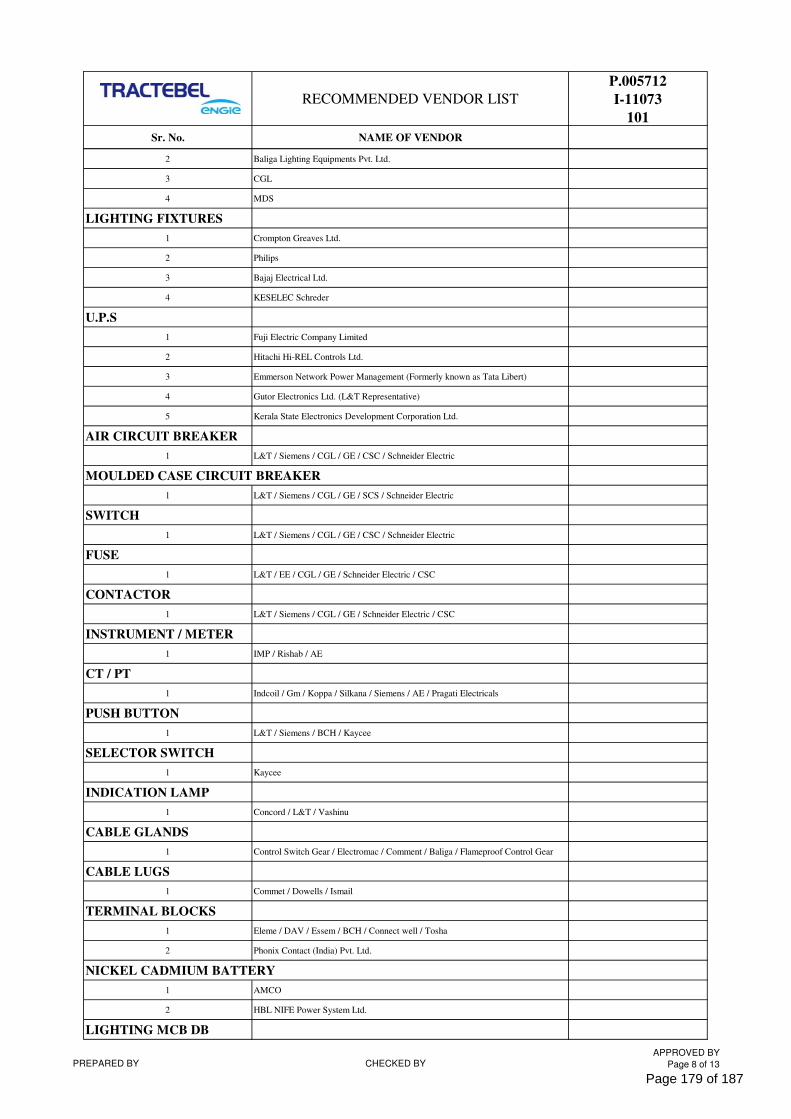
RECOMMENDED VENDOR LIST
P.005712
I-11073
101
Sr. No. NAME OF VENDOR
2 Baliga Lighting Equipments Pvt. Ltd.
3 CGL
4 MDS
LIGHTING FIXTURES
1 Crompton Greaves Ltd.
2 Philips
3 Bajaj Electrical Ltd.
4 KESELEC Schreder
U.P.S
1 Fuji Electric Company Limited
2 Hitachi Hi-REL Controls Ltd.
3 Emmerson Network Power Management (Formerly known as Tata Libert)
4 Gutor Electronics Ltd. (L&T Representative)
5 Kerala State Electronics Development Corporation Ltd.
AIR CIRCUIT BREAKER
1 L&T / Siemens / CGL / GE / CSC / Schneider Electric
MOULDED CASE CIRCUIT BREAKER
1 L&T / Siemens / CGL / GE / SCS / Schneider Electric
SWITCH
1 L&T / Siemens / CGL / GE / CSC / Schneider Electric
FUSE
1 L&T / EE / CGL / GE / Schneider Electric / CSC
CONTACTOR
1 L&T / Siemens / CGL / GE / Schneider Electric / CSC
INSTRUMENT / METER
1 IMP / Rishab / AE
CT / PT
1 Indcoil / Gm / Koppa / Silkana / Siemens / AE / Pragati Electricals
PUSH BUTTON
1 L&T / Siemens / BCH / Kaycee
SELECTOR SWITCH
1 Kaycee
INDICATION LAMP
1 Concord / L&T / Vashinu
CABLE GLANDS
1 Control Switch Gear / Electromac / Comment / Baliga / Flameproof Control Gear
CABLE LUGS
1 Commet / Dowells / Ismail
TERMINAL BLOCKS
1 Eleme / DAV / Essem / BCH / Connect well / Tosha
2 Phonix Contact (India) Pvt. Ltd.
NICKEL CADMIUM BATTERY
1 AMCO
2 HBL NIFE Power System Ltd.
LIGHTING MCB DB
PREPARED BY CHECKED BYAPPROVED BY
Page 8 of 13
Page 179 of 187
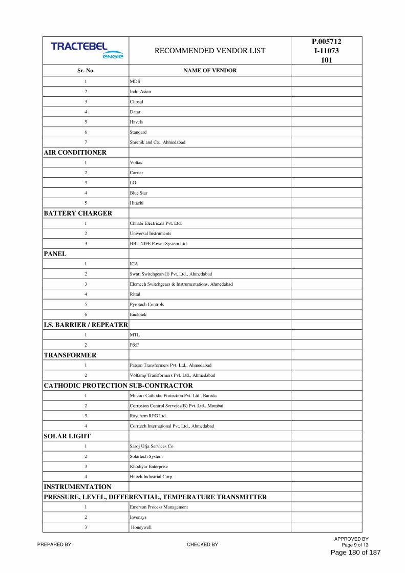
RECOMMENDED VENDOR LIST
P.005712
I-11073
101
Sr. No. NAME OF VENDOR
1 MDS
2 Indo-Asian
3 Clipsal
4 Datar
5 Havels
6 Standard
7 Shrenik and Co., Ahmedabad
AIR CONDITIONER
1 Voltas
2 Carrier
3 LG
4 Blue Star
5 Hitachi
BATTERY CHARGER
1 Chhabi Electricals Pvt. Ltd.
2 Universal Instruments
3 HBL NIFE Power System Ltd.
PANEL
1 ICA
2 Swati Switchgears(I) Pvt. Ltd., Ahmedabad
3 Elemech Switchgears & Instrumentations, Ahmedabad
4 Rittal
5 Pyrotech Controls
6 Enclotek
I.S. BARRIER / REPEATER
1 MTL
2 P&F
TRANSFORMER
1 Patson Transformers Pvt. Ltd., Ahmedabad
2 Voltamp Transformers Pvt. Ltd., Ahmedabad
CATHODIC PROTECTION SUB-CONTRACTOR
1 Mitcorr Cathodic Protection Pvt. Ltd., Baroda
2 Corrosion Control Servcies(B) Pvt. Ltd., Mumbai
3 Raychem RPG Ltd.
4 Corrtech International Pvt. Ltd., Ahmedabad
SOLAR LIGHT
1 Saroj Urja Services Co
2 Solartech System
3 Khodiyar Enterprise
4 Hitech Industrial Corp.
INSTRUMENTATION
PRESSURE, LEVEL, DIFFERENTIAL, TEMPERATURE TRANSMITTER
1 Emerson Process Management
2 Invensys
3 Honeywell
PREPARED BY CHECKED BYAPPROVED BY
Page 9 of 13
Page 180 of 187
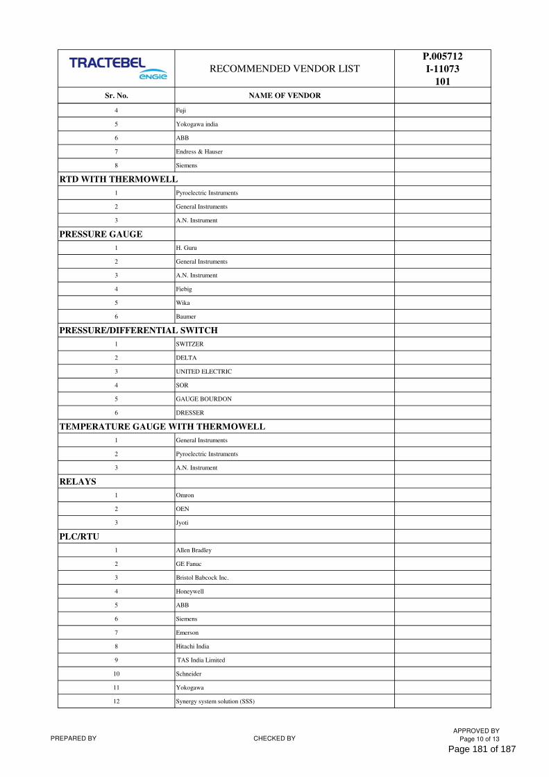
RECOMMENDED VENDOR LIST
P.005712
I-11073
101
Sr. No. NAME OF VENDOR
4 Fuji
5 Yokogawa india
6 ABB
7 Endress & Hauser
8 Siemens
RTD WITH THERMOWELL
1 Pyroelectric Instruments
2 General Instruments
3 A.N. Instrument
PRESSURE GAUGE
1 H. Guru
2 General Instruments
3 A.N. Instrument
4 Fiebig
5 Wika
6 Baumer
PRESSURE/DIFFERENTIAL SWITCH
1 SWITZER
2 DELTA
3 UNITED ELECTRIC
4 SOR
5 GAUGE BOURDON
6 DRESSER
TEMPERATURE GAUGE WITH THERMOWELL
1 General Instruments
2 Pyroelectric Instruments
3 A.N. Instrument
RELAYS
1 Omron
2 OEN
3 Jyoti
PLC/RTU
1 Allen Bradley
2 GE Fanuc
3 Bristol Babcock Inc.
4 Honeywell
5 ABB
6 Siemens
7 Emerson
8 Hitachi India
9 TAS India Limited
10 Schneider
11 Yokogawa
12 Synergy system solution (SSS)
PREPARED BY CHECKED BYAPPROVED BY
Page 10 of 13
Page 181 of 187
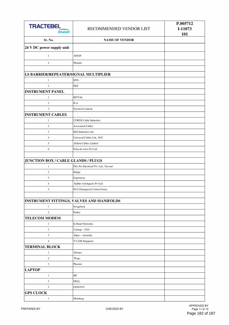
RECOMMENDED VENDOR LIST
P.005712
I-11073
101
Sr. No. NAME OF VENDOR
24 V DC power supply unit
1 SITOP
2 Phoenix
I.S BARRIER/REPEATER/SIGNAL MULTIPLIER
1 MTL
2 P&F
INSTRUMENT PANEL
1 RITTAL
2 ICA
3 Pyrotech Controls
INSTRUMENT CABLES
1 CORDS Cable Industries
2 Associated Cables
3 KEI Industries Ltd.
4 Universal Cables Ltd., M.P.
5 Delton Cables Limited
6 Polycab wires Pvt Ltd.
JUNCTION BOX / CABLE GLANDS / PLUGS
1 Flex Pro Electrical Pvt. Ltd., Navsari
2 Baliga
3 Exprotecta
4 Sudhir switchgears Pvt Ltd
5 FCG Flameproof Control Gears
INSTRUMENT FITTINGS, VALVES AND MANIFOLDS
1 Swagelock
2 Parker
TELECOM MODEM
1 In Hand Networks
2 Calamp – USA
3 Elpro – Australia
4 T-CAM Singapore
TERMINAL BLOCK
1 Elemex
2 Wago
3 Phoenix
LAPTOP
1 HP
2 DELL
3 LENOVO
GPS CLOCK
1 Meinberg
PREPARED BY CHECKED BYAPPROVED BY
Page 11 of 13
Page 182 of 187
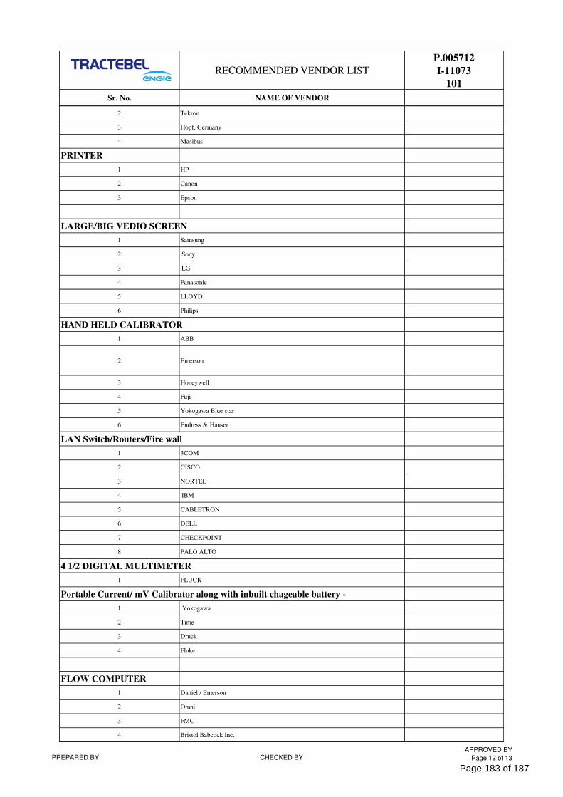
RECOMMENDED VENDOR LIST
P.005712
I-11073
101
Sr. No. NAME OF VENDOR
2 Tekron
3 Hopf, Germany
4 Masibus
PRINTER
1 HP
2 Canon
3 Epson
LARGE/BIG VEDIO SCREEN
1 Samsung
2 Sony
3 LG
4 Panasonic
5 LLOYD
6 Philips
HAND HELD CALIBRATOR
1 ABB
2 Emerson
3 Honeywell
4 Fuji
5 Yokogawa Blue star
6 Endress & Hauser
LAN Switch/Routers/Fire wall
1 3COM
2 CISCO
3 NORTEL
4 IBM
5 CABLETRON
6 DELL
7 CHECKPOINT
8 PALO ALTO
4 1/2 DIGITAL MULTIMETER
1 FLUCK
Portable Current/ mV Calibrator along with inbuilt chageable battery -
1 Yokogawa
2 Time
3 Druck
4 Fluke
FLOW COMPUTER
1 Daniel / Emerson
2 Omni
3 FMC
4 Bristol Babcock Inc.
PREPARED BY CHECKED BYAPPROVED BY
Page 12 of 13
Page 183 of 187
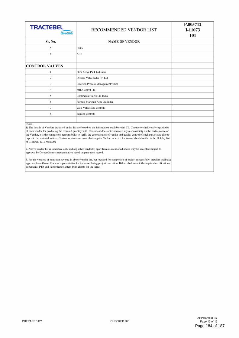
RECOMMENDED VENDOR LIST
P.005712
I-11073
101
Sr. No. NAME OF VENDOR
5 Elster
6 ABB
CONTROL VALVES
1 Flow Serve PVT Ltd India
2 Dresser Valve India Pvt Ltd
3 Emerson Process Management/fisher
4 MIL Control Ltd
5 Continental Valve Ltd India
6 Forbess Marshall Arca Ltd India
7 Weir Valves and controls
8 Samson controls
Note :
1) The details of Vendors indicated in this list are based on the information available with TE, Contractor shall verify capabilities
of each vendor for producing the required quantity with. Consultant does not Guarantee any responsibility on the performance of
the Vendor, it is the contractor's responsibility to verify the correct status of vendor and quality control of each parties and also to
expedite the material in time. Contractors to also ensure that supplier / bidder selected for Award should not be in the Holiday list
of CLIENT/ EIL/ MECON
2. Above vendor list is indicative only and any other vendor(s) apart from as mentioned above may be accepted subject to
approval by Owner/Owners representative based on past track record.
3. For the vendors of items not covered in above vendor list, but required for completion of project successfully, supplier shall take
approval form Owner/Owners representative for the same during project execution. Bidder shall submit the required certifications,
documents, PTR and Performance letters from clients for the same
PREPARED BY CHECKED BYAPPROVED BY
Page 13 of 13
Page 184 of 187
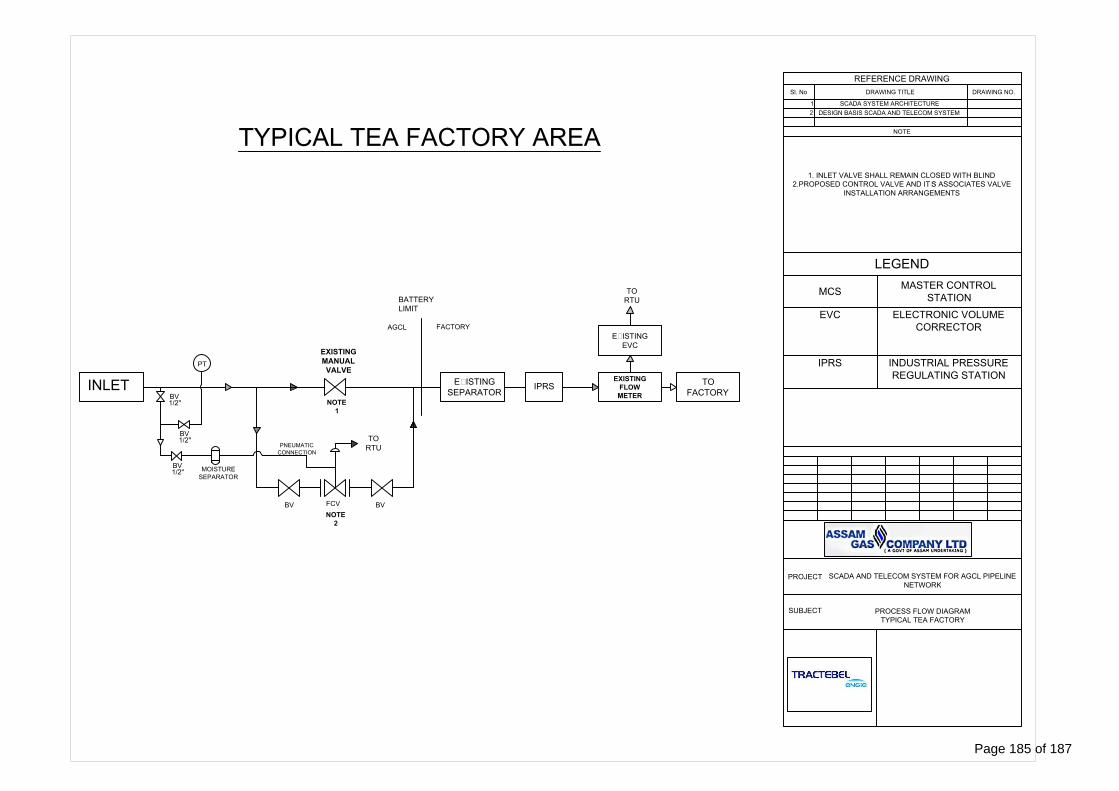
INLET
EXISTING
SEPARATOR
IPRS
MOISTURE
SEPARATOR
PT
FCV
BV BV
EXISTING
FLOW
METER
TO
FACTORY
EXISTING
EVC
FACTORY
BATTERY
LIMIT
TO
RTU
TO
RTU
NOTE
1
NOTE
2
REFERENCE DRAWING
Sl. No DRAWING TITLE DRAWING NO.
1 SCADA SYSTEM ARCHITECTURE
2 DESIGN BASIS SCADA AND TELECOM SYSTEM
NOTE
1/2"
1. INLET VALVE SHALL REMAIN CLOSED WITH BLIND
2.PROPOSED CONTROL VALVE AND IT'S ASSOCIATES VALVE
INSTALLATION ARRANGEMENTS
EXISTING
MANUAL
VALVE
BV
PNEUMATIC
CONNECTION
AGCL
LEGEND
MCS
MASTER CONTROL
STATION
EVC ELECTRONIC VOLUME
CORRECTOR
IPRS INDUSTRIAL PRESSURE
REGULATING STATION
PROJECT
SCADA AND TELECOM SYSTEM FOR AGCL PIPELINE
NETWORK
SUBJECT
PROCESS FLOW DIAGRAM
TYPICAL TEA FACTORY
1/2"
BV
1/2"
BV
TYPICAL TEA FACTORY AREA
Page 185 of 187
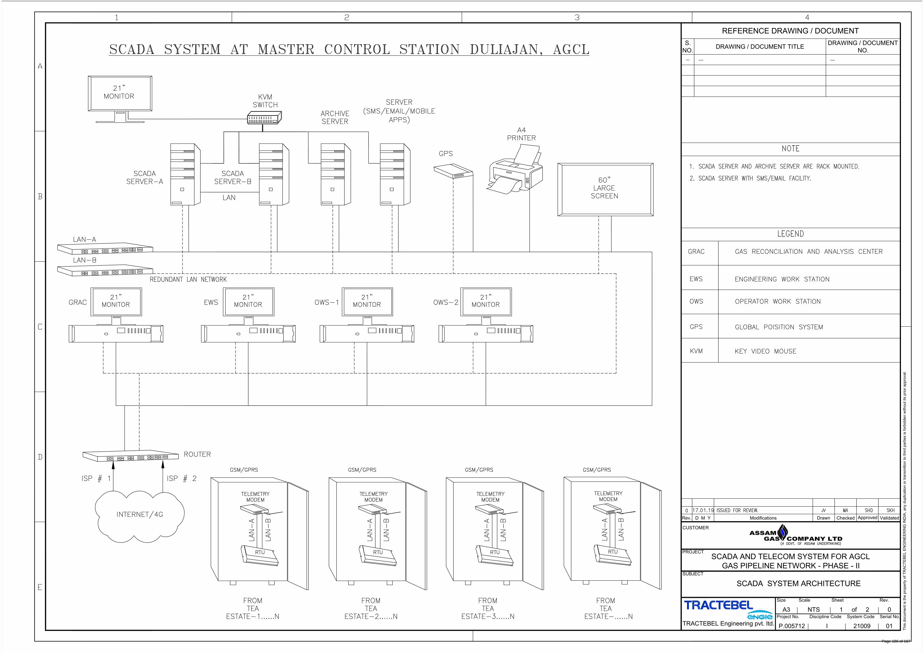
Rev. D M Y Modifications Drawn Checked
Approved
Validated
Th
is d
ocu
me
nt is th
e p
ro
pe
rty o
f T
RA
CT
EB
EL
E
NG
IN
EE
RIN
G IN
DIA
, a
ny d
up
lica
tio
n o
r tra
nsm
itio
n to
th
ird
p
artie
s is fo
rb
id
de
n w
ith
ou
t its p
rio
r a
pp
ro
va
l.
Project No. Discipline Code System Code Serial No.
Sheet
SUBJECT
PROJECT
CUSTOMER
A3 NTS 1 of 2
Size
0
Scale
P.005712
Rev.
I 21009 01
TRACTEBEL Engineering pvt. ltd.
SCADA SYSTEM ARCHITECTURE
REFERENCE DRAWING / DOCUMENT
S.
NO.
DRAWING / DOCUMENT TITLE
DRAWING / DOCUMENT
NO.
ASSAMGAS COMPANY LTD
SCADA AND TELECOM SYSTEM FOR AGCL
GAS PIPELINE NETWORK - PHASE - II
Page 186 of 187
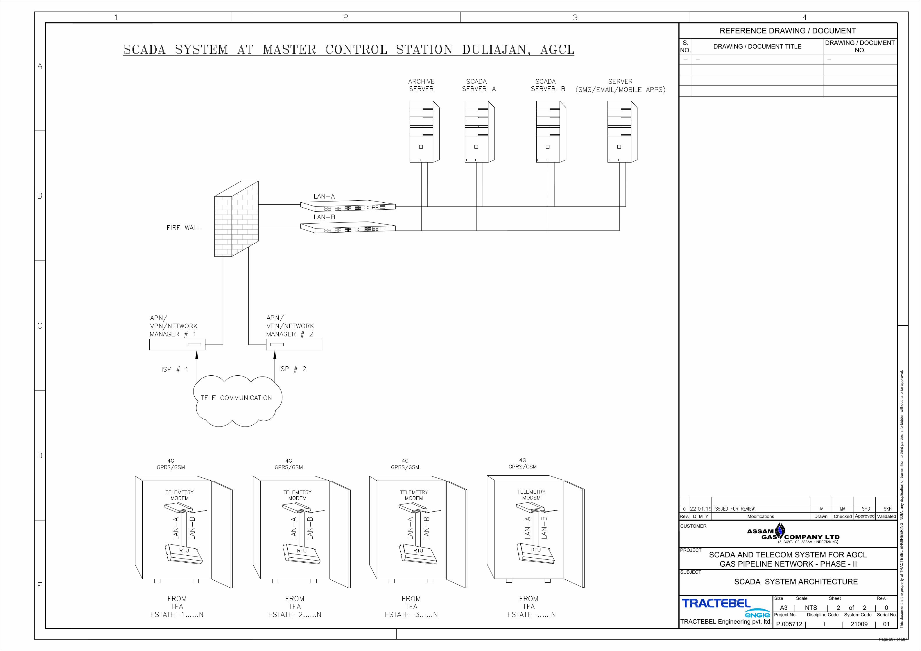
Th
is d
ocu
me
nt is th
e p
ro
pe
rty o
f T
RA
CT
EB
EL
E
NG
IN
EE
RIN
G IN
DIA
, a
ny d
up
lica
tio
n o
r tra
nsm
itio
n to
th
ird
p
artie
s is fo
rb
id
de
n w
ith
ou
t its p
rio
r a
pp
ro
va
l.
REFERENCE DRAWING / DOCUMENT
S.
NO.
DRAWING / DOCUMENT TITLE
DRAWING / DOCUMENT
NO.
Rev. D M Y Modifications Drawn Checked
Approved
Validated
Project No. Discipline Code System Code Serial No.
Sheet
SUBJECT
PROJECT
CUSTOMER
A3 NTS 2 of 2
Size
0
Scale
P.005712
Rev.
I 21009 01
TRACTEBEL Engineering pvt. ltd.
SCADA SYSTEM ARCHITECTURE
ASSAMGAS COMPANY LTD
SCADA AND TELECOM SYSTEM FOR AGCL
GAS PIPELINE NETWORK - PHASE - II
Page 187 of 187

At the helm of the Energy Transition, Tractebel provides a full range of engineering and consulting servicesthroughout the life cycle of its clients’ projects, including design and project management. As one of the world’slargest engineering consultancy companies and with more than 150 years of experience, it's our mission to activelyshape the world of tomorrow. With about 5,000 experts and offices in 33 countries, we are able to offer ourcustomers multidisciplinary solutions in energy, water and urban.
TRACTEBEL ENGINEERING PVT. LTD.Intec House 37Institutional Area, Sector 44122 002 - Gurgaon - INDIAtractebel-engie.com
Syed Kaiumul HUSSAINtel. +91 124 471 2200fax +91 124 469 [email protected]