Embed Size (px)
Citation preview

SCADAPack E Target 5Modbus CommunicationInterfaces
SCADAPack E Target 5 Modbus Communication Interfaces2
Table of Contents
Part I SCADAPack E Target 5 ModbusCommunication Interfaces 4
................................................................................................................................... 41 Technical Support
................................................................................................................................... 52 Safety Information
................................................................................................................................... 83 Overview
................................................................................................................................... 94 Modbus Master/Client Operation
.......................................................................................................................................................... 9I/O Device Types and Modbus Addressing Terminology 4.1.......................................................................................................................................................... 10Serial Modbus I/O Devices 4.2......................................................................................................................................................... 11Modbus Input Devices4.2.1......................................................................................................................................................... 12Modbus Output Devices4.2.2.......................................................................................................................................................... 13Modbus TCP I/O Device Interface 4.3......................................................................................................................................................... 14Modbus/TCP Input Devices4.3.1......................................................................................................................................................... 15Modbus/TCP Output Devices4.3.2......................................................................................................................................................... 16Open Modbus/TCP Conformance Classes4.3.3.......................................................................................................................................................... 18Modbus RTU in TCP I/O Device Interface 4.4......................................................................................................................................................... 18Modbus RTU in TCP Input Devices4.4.1......................................................................................................................................................... 19Modbus RTU in TCP Output Devices4.4.2.......................................................................................................................................................... 20Modbus PLC Data Types 4.5.......................................................................................................................................................... 22Communication Interfaces 4.6......................................................................................................................................................... 22Serial Modbus Communications4.6.1......................................................................................................................................................... 23Modbus/TCP Client Communications4.6.2......................................................................................................................................................... 24Modbus/TCP Server Communications4.6.3......................................................................................................................................................... 24Modbus RTU in TCP Client Communications4.6.4......................................................................................................................................................... 25BOOTP Server Configuration4.6.5
......................................................................................................................................... 26Configuring BOOTP w ith SCADAPack E Configurator4.6.5.1
......................................................................................................................................... 27Configuring BOOTP from the Command Line4.6.5.2.......................................................................................................................................................... 28System Points 4.7......................................................................................................................................................... 30Modbus Status Values4.7.1......................................................................................................................................................... 31Data Cache Time4.7.2......................................................................................................................................................... 31PLC Output Device Default Background Update Rate4.7.3.......................................................................................................................................................... 32Replacing a Modbus/TCP or Modbus RTU in TCP Device that uses BOOTP 4.8
......................................................................................................................................................... 32
Change a Modbus/TCP or Modbus RTU in TCP Device Using SCADAPack E
Configurator4.8.1
......................................................................................................................................................... 33
Change a Modbus/TCP or Modbus RTU in TCP Device Using COMMAND
LINE4.8.2
................................................................................................................................... 345 Modbus Slave/Server Operation
.......................................................................................................................................................... 34Setting up Modbus Slave / Server 5.1
.......................................................................................................................................................... 35Modbus Slave and Modbus /TCP Server Implementation Conditions 5.2......................................................................................................................................................... 35Conformance Classes & Supported Function Codes5.2.1......................................................................................................................................................... 36Modbus Address Mapping to RTU Point Address Space5.2.2
......................................................................................................................................... 38Binary Addresses5.2.2.1
......................................................................................................................................... 39Analog Addresses5.2.2.2................................................................................................................................... 40Reading Analog Registers5.2.2.2.1................................................................................................................................... 42Writing Analog Registers5.2.2.2.2
......................................................................................................................................... 43Modbus Register / 32-bit Analog Point Mapping Configuration5.2.2.3
......................................................................................................................................... 45Supported Data Types5.2.2.4
3Contents
3
......................................................................................................................................................... 47Exception Codes5.2.3......................................................................................................................................... 47Read & Write Multiple Coils / Register Exceptions5.2.3.1......................................................................................................................................... 48Exceptions Writing to RTU Points5.2.3.2
.......................................................................................................................................................... 48System Points 5.3......................................................................................................................................................... 49Modbus/TCP Server Unit Identif ier5.3.1......................................................................................................................................................... 49Modbus Slave Address5.3.2.......................................................................................................................................................... 50Diagnostics 5.4
................................................................................................................................... 516 Modbus/TCP Operation
................................................................................................................................... 527 Modbus RTU in TCP Operation
................................................................................................................................... 538 Modbus Protocol Technical Information
.......................................................................................................................................................... 53Modbus Serial Communication Format 8.1
.......................................................................................................................................................... 54CRC16 Calculation Method 8.2
.......................................................................................................................................................... 55Open Modbus/TCP Communication Format 8.3
.......................................................................................................................................................... 56Modbus RTU in TCP Communication Format 8.4

SCADAPack E Target 5 Modbus Communication Interfaces4
I SCADAPack E Target 5 Modbus CommunicationInterfaces
©2013 Control Microsystems Inc. All rights reserved.Printed in Canada.
Version: 8.05.4
The information provided in this documentation contains general descriptions and/or technicalcharacteristics of the performance of the products contained herein. This documentation isnot intended as a substitute for and is not to be used for determining suitability or reliability ofthese products for specific user applications. It is the duty of any such user or integrator toperform the appropriate and complete risk analysis, evaluation and testing of the productswith respect to the relevant specific application or use thereof. Neither Schneider Electric norany of its affiliates or subsidiaries shall be responsible or liable for misuse of the informationcontained herein. If you have any suggestions for improvements or amendments or havefound errors in this publication, please notify us.
No part of this document may be reproduced in any form or by any means, electronic ormechanical, including photocopying, without express written permission of SchneiderElectric.
All pertinent state, regional, and local safety regulations must be observed when installing andusing this product. For reasons of safety and to help ensure compliance with documentedsystem data, only the manufacturer should perform repairs to components.
When devices are used for applications with technical safety requirements, the relevantinstructions must be followed. Failure to use Schneider Electric software or approvedsoftware with our hardware products may result in injury, harm, or improper operating results.
Failure to observe this information can result in injury or equipment damage.
1 Technical Support
Support related to any part of this documentation can be directed to one of the followingsupport centers.

SCADAPack E Target 5 Modbus Communication Interfaces 5
Technical Support: The Americas
Available Monday to Friday 8:00am – 6:30pm Eastern Time
Toll free within North America 1-888-226-6876
Direct Worldwide +1-613-591-1943
Email [email protected]
Technical Support: Europe
Available Monday to Friday 8:30am – 5:30pm Central European Time
Direct Worldwide +31 (71) 597-1655
Email [email protected]
Technical Support: Asia
Available Monday to Friday 8:00am – 6:30pm Eastern Time (North America)
Direct Worldwide +1-613-591-1943
Email [email protected]
Technical Support: Australia
Inside Australia 1300 369 233
Email [email protected]
2 Safety Information
Read these instructions carefully, and look at the equipment to become familiar with thedevice before trying to install, operate, or maintain it. The following special messages mayappear throughout this documentation or on the equipment to warn of potential hazards or tocall attention to information that clarifies or simplifies a procedure.
The addition of this symbol to a Danger or Warning safety labelindicates that an electrical hazard exists, which will result in personalinjury if the instructions are not followed.
This is the safety alert symbol. It is used to alert you to potentialpersonal injury hazards. Obey all safety messages that follow thissymbol to avoid possible injury or death.
SCADAPack E Target 5 Modbus Communication Interfaces6
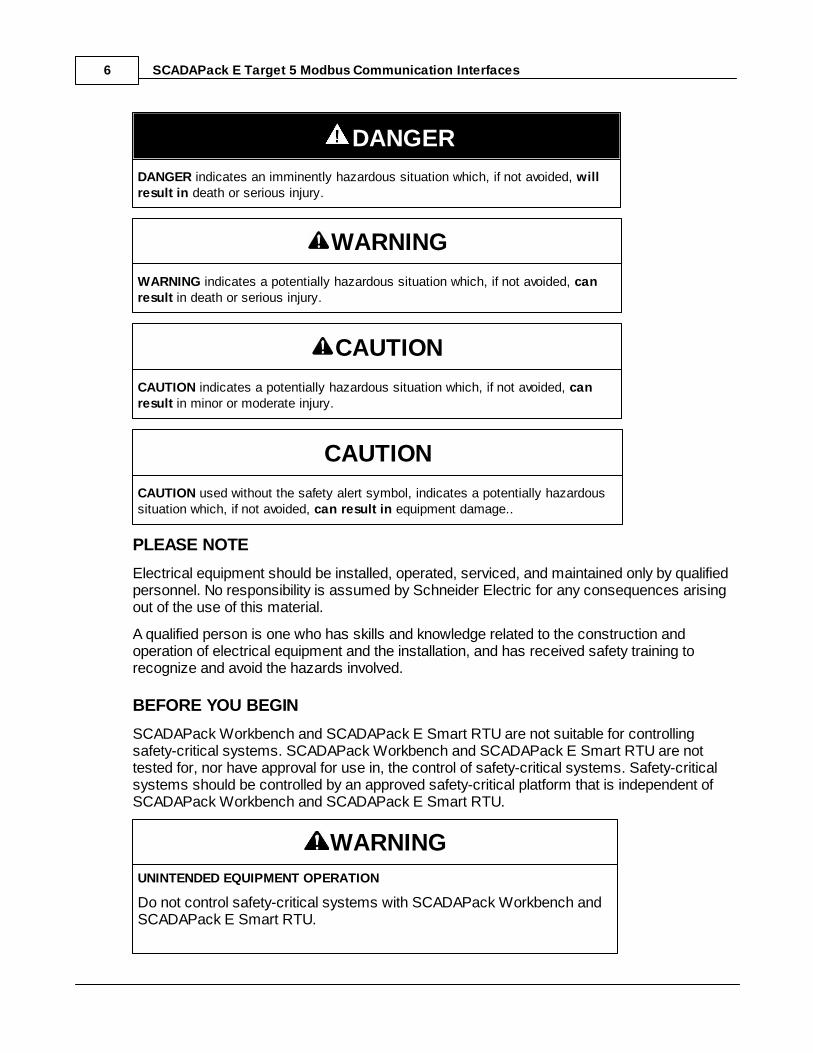
DANGER
DANGER indicates an imminently hazardous situation which, if not avoided, willresult in death or serious injury.
WARNING
WARNING indicates a potentially hazardous situation which, if not avoided, canresult in death or serious injury.
CAUTION
CAUTION indicates a potentially hazardous situation which, if not avoided, canresult in minor or moderate injury.
CAUTION
CAUTION used without the safety alert symbol, indicates a potentially hazardoussituation which, if not avoided, can result in equipment damage..
PLEASE NOTE
Electrical equipment should be installed, operated, serviced, and maintained only by qualifiedpersonnel. No responsibility is assumed by Schneider Electric for any consequences arisingout of the use of this material.
A qualified person is one who has skills and knowledge related to the construction andoperation of electrical equipment and the installation, and has received safety training torecognize and avoid the hazards involved.
BEFORE YOU BEGIN
SCADAPack Workbench and SCADAPack E Smart RTU are not suitable for controllingsafety-critical systems. SCADAPack Workbench and SCADAPack E Smart RTU are nottested for, nor have approval for use in, the control of safety-critical systems. Safety-criticalsystems should be controlled by an approved safety-critical platform that is independent ofSCADAPack Workbench and SCADAPack E Smart RTU.
WARNING
UNINTENDED EQUIPMENT OPERATION
Do not control safety-critical systems with SCADAPack Workbench andSCADAPack E Smart RTU.
SCADAPack E Target 5 Modbus Communication Interfaces 7
Failure to follow these instructions can result in death, serious injury orequipment damage.
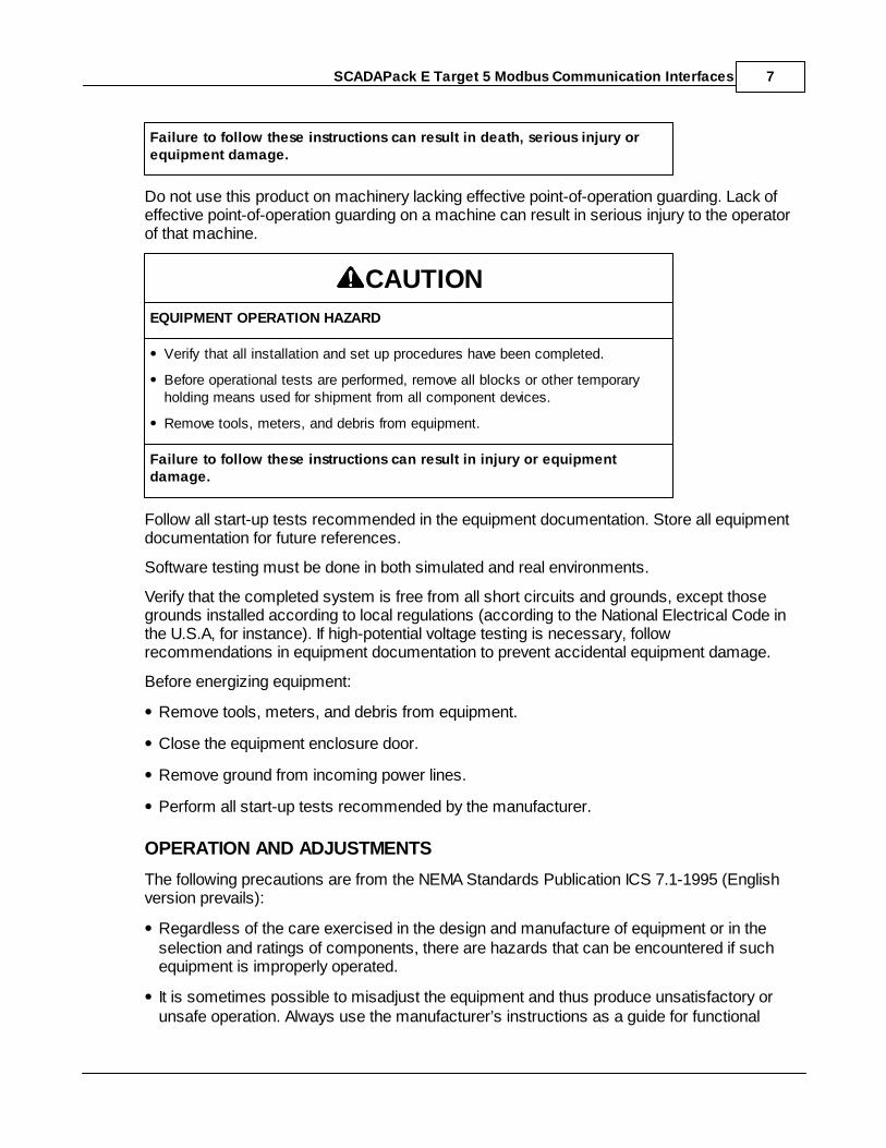
Do not use this product on machinery lacking effective point-of-operation guarding. Lack ofeffective point-of-operation guarding on a machine can result in serious injury to the operatorof that machine.
CAUTION
EQUIPMENT OPERATION HAZARD
Verify that all installation and set up procedures have been completed.
Before operational tests are performed, remove all blocks or other temporaryholding means used for shipment from all component devices.
Remove tools, meters, and debris from equipment.
Failure to follow these instructions can result in injury or equipmentdamage.
Follow all start-up tests recommended in the equipment documentation. Store all equipmentdocumentation for future references.
Software testing must be done in both simulated and real environments.
Verify that the completed system is free from all short circuits and grounds, except thosegrounds installed according to local regulations (according to the National Electrical Code inthe U.S.A, for instance). If high-potential voltage testing is necessary, followrecommendations in equipment documentation to prevent accidental equipment damage.
Before energizing equipment:
Remove tools, meters, and debris from equipment.
Close the equipment enclosure door.
Remove ground from incoming power lines.
Perform all start-up tests recommended by the manufacturer.
OPERATION AND ADJUSTMENTS
The following precautions are from the NEMA Standards Publication ICS 7.1-1995 (Englishversion prevails):
Regardless of the care exercised in the design and manufacture of equipment or in theselection and ratings of components, there are hazards that can be encountered if suchequipment is improperly operated.
It is sometimes possible to misadjust the equipment and thus produce unsatisfactory orunsafe operation. Always use the manufacturer’s instructions as a guide for functional
SCADAPack E Target 5 Modbus Communication Interfaces8
adjustments. Personnel who have access to these adjustments should be familiar with theequipment manufacturer’s instructions and the machinery used with the electricalequipment.
Only those operational adjustments actually required by the operator should be accessibleto the operator. Access to other controls should be restricted to prevent unauthorizedchanges in operating characteristics.
3 Overview
This document describes communication with other Modbus devices using Modbus RTU,Modbus/TCP, or Modbus RTU in TCP protocols.
Master/Slave and Client/Server Terminology
A Modbus Master or Modbus Client sends commands to another device. The Modbus Slaveor Modbus Server device responds to the commands.
The Modbus RTU and Modbus RTU protocols call the device sending the commands aModbus Master. The device responding to the commands is called a Modbus Slave.
The Modbus/TCP protocol calls the device sending the commands a Modbus Client. Thedevice responding to the commands is called a Modbus Server.
The SCADAPack E Smart RTU can operate as a Modbus Master or Modbus Client; and as aModbus Slave or Modbus/TCP Server. It supports simultaneous communication usingsupported protocols. It does not support Modbus ASCII protocol.
Assumed Knowledge
Familiarity with Modbus RTU, Modbus/TCP, or Modbus RTU in TCP protocols.
Target Audience
Systems Engineers
Commissioning Engineers
Maintenance Technicians
References
SCADAPack E Target 5 I/O Device Reference Manual
SCADAPack E Configurator User Manual
SCADAPack E Technical Reference Manuals.
SCADAPack E Target 5 Modbus Communication Interfaces 9
Workbench Help
Protocol documentation for various Modbus PLC devices
Open Modbus/TCP Specification Revision 1.0, March 1999
4 Modbus Master/Client Operation
A Modbus Master or Modbus Client sends commands to another device.
The Modbus RTU and Modbus RTU protocols call the device sending the commands aModbus Master.
The Modbus/TCP protocol calls the device sending the commands a Modbus Client.
These sections describe operation as a Master/Client.
I/O device Types & Modbus Addressing Terminology
Serial Modbus I/O device Interfaces
Modbus TCP I/O device Interface
Modbus RTU in TCP I/O device Interface
Communications Interface
Replacing a Modbus/TCP or Modbus RTU in TCP Device that uses BOOTP
4.1 I/O Device Types and Modbus Addressing Terminology
The SCADAPack E Smart RTU controller provides three groups of Modbus I/O Devices. Seethe SCADAPack E Target 5 I/O Device Manual for details.
A maximum of 200 PLC Device I/O Devices (total of every PLC type) may be configured intotal per Resource.
Modbus RTU Protocol
I/O Devices beginning with MBUS... communicate using the Modbus RTU protocol.
Modbus RTU operates on serial ports. One or more serial ports must be configured as a PLCDevice. The RTU communication port data rate and parity format are used. RS232, RS422and RS485 communications are supported.
9
10
13
18
22
32
SCADAPack E Target 5 Modbus Communication Interfaces10
Modbus/TCP Protocol
I/O Devices beginning with MTCP... communicate using the Modbus/TCP protocol.
Modbus/TCP operates on TCP/IP networks. The Modbus/IP (Client) service must beenabled. The protocol connects TCP sockets between the Modbus client and server. TCP/IPover Ethernet and PPP communications are supported.
Modbus RTU in TCP Protocol
I/O Devices beginning with MRTUTCP... communicate using the Modbus RTU in TCPprotocol.
Modbus RTU in TCP operates on TCP/IP networks. The Modbus/IP (Client) service must beenabled. The protocol connects TCP sockets between the Modbus client and server. TCP/IPover Ethernet and PPP communications are supported.
Modbus Addressing Terminology
The SCADAPack E Smart RTU uses 5-digit Modbus address numbering, where the leadingdigit generally represents the register data type. In addition, the numbering within eachregister data type adheres to the classical Modicon PLC numbering convention, commencingat register 1. For example: A register read by the SCADAPack E Smart RTU specifyingModbus register 40010 is represented by Modbus protocol function code 3, protocol registeraddress 0x0009.
Some Modbus systems use 6-digit addressing, as opposed to the 5-digit Modbus registeraddressing described above. 6-digit addressing is designed to enable access to additionalregisters in each register range. A 6 digit address is made up of a single digit numeric prefixand a 5-digit Modbus register number. For example: Registers 300001 – 309999 areequivalent to 5-digit Modbus register addresses 30001 – 39999. However, input registers310000 – 365536 in a remote PLC device are not addressable with the SCADAPack ESmart RTU 5-digit register address.
In the 5-digit addressing regime, HOLDING REGISTERS are extended beyond register49999. RTU Modbus register addresses 50000 – 65535 can be addressed in a remote PLCdevice, and are the equivalent to 6-digit holding register numbers 450000 – 465535. So theSCADAPack E RTU can access remote PLC device holding registers equivalent to the (6-digit) range 400001-409999 & 450000-465535.
4.2 Serial Modbus I/O Devices
I/O Devices beginning with MBUS... communicate using the Modbus RTU protocol usingserial ports configured as PLC Device.
Each I/O device can access different PLC register data within the same PLC device, or indifferent PLCs. For example, multi-drop RS485 permits many uniquely addressed Modbus
SCADAPack E Target 5 Modbus Communication Interfaces 11
PLCs to be connected to a serial port. In addition, multiple I/O Devices may be configured touse different RTU serial ports configured as a PLC Device.
Each I/O device uses a separate Modbus request to read or write its data. Improvedcommunication efficiency can be achieved by grouping Modbus registers together and usingfewer I/O Devices with a larger number of channels, rather than more I/O Devices with asmaller number of channels.
A maximum of 200 PLC Device I/O Devices (total of every PLC type) may be configured intotal per IEC 61131-3 Resource.
Communication status is available on the first 60 I/O Devices for IEC 61131-3 Resource 1,and 14 I/O Devices for IEC 61131-3 Resource 2. See Section System Points for moreinformation.
Modbus Input devices
Modbus Output devices
4.2.1 Modbus Input Devices
Modbus input device variables are updated at the start of the IEC 61131-3 Resource scan. The value presented to the IEC 61131-3 variables is the value returned by the PLC to theprevious read request. This read may have occurred during previous resource scans.
The data update rate parameter on the I/O device sets the scan rate of the PLC data. ThePLC communication status is updated if there is a status code returned from the PLC, or noresponse from the PLC after a data request by the RTU (see Section Modbus Status Values
). The status is cleared upon successful communications. To catch transient statuscodes, you can use IEC 61131-3 logic to store non-zero values.
Input Device Parameters
first_register: specifies the Modbus data registers to access when reading PLC data intoIEC 61131-3 variables. The PLC data type accessed is specific to the PLC Device I/O devicetype and device address.
register_format: specifies the Modbus PLC data register type. Various PLC data types aresupported. See Modbus PLC Data Types .
data_update_rate: specifies the rate in milliseconds (ms) at which the data for the inputdevice is extracted from the PLC. Individual I/O Devices may have different data update ratesallowing prioritization of data extracted from a PLC. The SCADAPack E Smart RTU may notbe able to read requested PLC data within the time set by the data update rate depending onthe quantity of data to be read, rate of write requests and PLC communication speed. In thiscase the update rates will be slower.
plc_device_addr: specifies the PLC device address. Modbus PLC devices on the samecommunication channel need to have unique device addresses. Logic may access data frommultiple PLCs via the same communication interface. In this case a separate I/O device will
48
11
12
30
20
SCADAPack E Target 5 Modbus Communication Interfaces12
be required for each PLC device. Values for this parameter are usually in the range 1-254.
timeout: specifies the communications timeout on an individual I/O device. The timeoutapplies to communications associated with that device. Where this value is “0”, the PLCdevice driver will use the default timeout (1200ms). Units for this field are the millisecond(ms).
port: specifies which serial port will be used to communicate with the PLC. The port must beconfigured as a PLC Device. If only one PLC Device port is configured, this field is ignored.
Controlling PLC Device Communications
Communication using these I/O Devices can be controlled by the function block mbusctrlusing the En_RD parameter. See SCADAPack E Target 5 Function Block Reference fordetails.
4.2.2 Modbus Output Devices
Modbus output device variables are updated at the end of the IEC 61131-3 Resource scan.
Output variables are written to the PLC:
When the value of a variable attached to the output device changes. They are sent to thePLC after this occurs, but the scan continues executing while the PLC communications arein progress. In order words, communications to the PLC is occurs asynchronously to theprogram scan.
When the IEC 61131-3 Resource starts.
When the PLC does not respond to a command, it is re-sent until the PLC responds.
When the data update rate configured for the output device is reached.
Output Device Parameters
first_register: specifies the Modbus data registers to access when reading PLC data intoIEC 61131-3 variables. The PLC data type accessed is specific to the PLC Device I/O devicetype and device address.
register_format: specifies the Modbus PLC data register type. Various PLC data types aresupported. See Modbus PLC Data Types .
data_update_rate: specifies the rate in milliseconds (ms) at which the data for the outputdevice is written to the PLC. Between data_update_rate periods, data is written to the PLConly when the output variable values change. Individual I/O Devices may have different dataupdate rates allowing prioritization of data sent to a PLC Device. Setting this parameter to 0disables the time-based writing of output data. Data is written at IEC 61131-3 Resourcestartup and thereafter only when individual output variables change. See PLC Output deviceDefault Background Update Rate .
20
31
SCADAPack E Target 5 Modbus Communication Interfaces 13
plc_device_addr: specifies the PLC device address. Modbus PLC devices on the samecommunication channel need to have unique device addresses. Logic may access data frommultiple PLCs via the same communication interface. In this case a separate I/O device willbe required for each PLC device. Values for this parameter are usually in the range 1-254.
timeout: specifies the communications timeout on an individual I/O device. The timeoutapplies to communications associated with that device. Where this value is “0”, the PLCdevice driver will use the default timeout (1200ms). Units for this field are the millisecond(ms).
port: specifies which serial port will be used to communicate with the PLC. The port must beconfigured as a PLC Device. If only one PLC Device port is configured, this field is ignored.
Controlling PLC Device Communications
Communication using these I/O Devices can be controlled by the function block mbusctrlusing the En_WR parameter. See SCADAPack E Target 5 Function Block Reference fordetails.
Remote Device Requirements
The device to which Modbus Output commands are sent needs to provide Modbus registeraddresses for each of the channels on the output device, regardless of whether variables areattached to the channels, or not. For example, for a 16-channel device, 16 contiguousModbus registers need to be present in the remote device.
4.3 Modbus TCP I/O Device Interface
I/O Devices beginning with MTCP... communicate using the Modbus/TCP protocol.
Each I/O device uses a separate Modbus/TCP request to read or write its data. Improvedcommunication efficiency can be achieved by grouping Modbus registers together and usingfewer I/O Devices with a larger number of channels, rather than more I/O Devices with asmaller number of channels.
A maximum of 200 PLC Device I/O Devices (total of every PLC type) may be configured intotal per IEC 61131-3 Resource.
A corresponding pair of system points relates to each PLC Slave I/O device as described inSection System Points .
Communication using these I/O Devices can be controlled by an function block: mtcpctrl.
Modbus/TCP Input devices
Modbus/TCP Output devices
Open Modbus/TCP Conformance Classes
48
14
15
16

SCADAPack E Target 5 Modbus Communication Interfaces14
4.3.1 Modbus/TCP Input Devices
Modbus/TCP input device variables are updated at the start of the IEC 61131-3 Resourcescan. The value presented to the IEC 61131-3 variables is the value returned by the PLC tothe previous read request. This read may have occurred during previous resource scans.
The data update rate parameter on the I/O device sets the scan rate of the PLC data. ThePLC communication status is updated if there is a status code returned from the PLC, or noresponse from the PLC after a data request by the RTU (see Section Modbus Status Values
). The status is cleared upon successful communications. To catch transient statuscodes, you can use IEC 61131-3 logic to store non-zero values.
Input Device Parameters
first_register: specifies the Modbus data registers to access when reading PLC data intoIEC 61131-3 variables. The PLC data type accessed is specific to the PLC Device I/O devicetype and device address.
register_format: specifies the Modbus PLC data register type. Various PLC data types aresupported. See Modbus PLC Data Types .
data_update_rate: specifies the rate in milliseconds (ms) at which the data for the inputdevice is extracted from the PLC. Individual I/O Devices may have different data update ratesallowing prioritization of data extracted from a PLC. The SCADAPack E Smart RTU may notbe able to read requested PLC data within the time set by the data update rate depending onthe quantity of data to be read, rate of write requests and PLC communication speed. In thiscase the update rates will be slower.
plc_device_addr: specifies the PLC device address. Modbus PLC devices on the samecommunication channel need to have unique device addresses. Logic may access data frommultiple PLCs via the same communication interface. In this case a separate I/O device willbe required for each PLC device. Values for this parameter are usually in the range 1-254.
timeout: specifies the communications timeout on an individual I/O device. The timeoutapplies to communications associated with that device. Where this value is “0”, the PLCdevice driver will use the default timeout (1200ms). Units for this field are the millisecond(ms).
TCP_port: This parameter specifies the port number of the Modbus/TCP server. Default is502.
IP_address: This parameter specifies the IP network address that the SCADAPack E SmartRTU connects to for communication with the PLC for this I/O device. Enter the IP address ofthe Modbus/TCP PLC, or Modbus bridge if applicable.
Controlling PLC Device Communications
Communication using these I/O Devices can be controlled by the function block mtcpctrlusing the En_RD parameter. See SCADAPack E Target 5 Function Block Reference for
30
20
SCADAPack E Target 5 Modbus Communication Interfaces 15
details.
4.3.2 Modbus/TCP Output Devices
Modbus/TCP output device variables are updated at the end of the IEC 61131-3 Resourcescan.
Output variables are written to the PLC:
When the value of a variable attached to the output device changes.
When the IEC 61131-3 Resource starts.
When the PLC does not respond to a command, it is re-sent until the PLC responds.
When the data update rate configured for the output device is reached.
Output Device Parameters
first_register: specifies the Modbus data registers to access when reading PLC data intoIEC 61131-3 variables. The PLC data type accessed is specific to the PLC Device I/O devicetype and device address.
register_format: specifies the Modbus PLC data register type. Various PLC data types aresupported. See Modbus PLC Data Types .
data_update_rate: specifies the rate in milliseconds (ms) at which the data for the outputdevice is written to the PLC. Between data_update_rate periods, data is written to the PLConly when the output variable values change. Individual I/O Devices may have different dataupdate rates allowing prioritization of data sent to a PLC Device. Setting this parameter to 0disables the time-based writing of output data. Data is written at IEC 61131-3 Resourcestartup and thereafter only when individual output variables change. See PLC Output deviceDefault Background Update Rate .
plc_device_addr: specifies the PLC device address. Modbus PLC devices accessed at thesame IP address (e.g. via a Modbus bridge) need to have a unique unit address in order to beidentified. Logic may access data from different units on the same IP address or at differentIP addresses. In these cases a separate I/O device will be required for each device.
timeout: specifies the communications timeout on an individual I/O device. The timeoutapplies to communications associated with that device. Where this value is “0”, the PLCdevice driver will use the default timeout (1200ms). Units for this field are the millisecond(ms).
TCP_port: This parameter specifies the port number of the Modbus/TCP server. Default is502.
IP_address: This parameter specifies the IP network address that the SCADAPack E SmartRTU connects to for communication with the PLC for this I/O device. Enter the IP address ofthe Modbus/TCP PLC, or Modbus bridge if applicable.
20
31
SCADAPack E Target 5 Modbus Communication Interfaces16
Controlling PLC Device Communications
Communication using these I/O Devices can be controlled by the function block mbusctrlusing the En_WR parameter. See SCADAPack E Target 5 Function Block Reference fordetails.
Remote Device Requirements
The device to which Modbus Output commands are sent needs to provide Modbus registeraddresses for each of the channels on the output device, regardless of whether variables areattached to the channels, or not. For example, for a 16-channel device, 16 contiguousModbus registers need to be present in the remote device.
4.3.3 Open Modbus/TCP Conformance Classes
The Open Modbus/TCP standard defines conformance classes for Master & Slave (Client &Server) devices.
When using the PLC I/O Devices in the following way, the SCADAPack E RTU conforms tothe requirements for Open Modbus/TCP Conformance CLASS 0 devices:
MTCP_BOOL_READ
– device address: 40001-65535
plc data type: IEC DISCRETE
uses Modbus function code 3 – read multiple registers
MTCP_BOOL_WRITE
– device address: 40001-65535
plc data type: IEC DISCRETE
uses Modbus function code 16 – write multiple registers
MTCP_INT_READ
MTCP_DINT_READ
MTCP_UINT_READ
MTCP_REAL_READ
– device address: 40001-65535
plc data type: IEC INT, IEC UINT, IEC DINT, IEC REAL
uses Modbus function code 3 – read multiple registers
MTCP_INT_WRITE
MTCP_DINT_WRITE
– device address: 40001-65535
plc data type: IEC INT, IEC UINT, IEC DINT, IEC REAL
uses Modbus function code 16 – write multiple registers
SCADAPack E Target 5 Modbus Communication Interfaces 17
MTCP_UINT_WRITE
MTCP_REAL_WRITE
Use of the PLC I/O Devices in the following ways requires the PLC slave device (OpenModbus/TCP server) to be at least an Open Modbus/TCP Conformance CLASS 1 device:
MTCP_BOOL_READ
– device address: 1-9999
plc data type: IEC DISCRETE
uses Modbus function code 1 – read coils
MTCP_BOOL_WRITE
– device address: 10001-19999
plc data type: IEC DISCRETE
uses Modbus function code 2 – read input discrete (status)
MTCP_INT_READ
MTCP_DINT_READ
MTCP_UINT_READ
MTCP_REAL_READ
– device address: 30001-39999
plc data type: IEC INT, IEC UINT, IEC DINT, IEC REAL
uses Modbus function code 4 – read input registers
MTCP_INT_WRITE
MTCP_DINT_WRITE
MTCP_UINT_WRITE
MTCP_REAL_WRITE
– device address: 1-9999
plc data type: IEC INT, IEC UINT, IEC DINT, IEC REAL
uses Modbus function code 5 – write coil
PLC data type options additional to those listed here are available. The above types are aselection of those defined in the Open Modbus/TCP Conformance Classes. Refer to ModbusPLC Data Types for a complete listing of supported data types.20
SCADAPack E Target 5 Modbus Communication Interfaces18
4.4 Modbus RTU in TCP I/O Device Interface
I/O Devices beginning with MRTUTCP... communicate using the Modbus RTU in TCPprotocol.
Each I/O device uses a separate Modbus RTU in TCP request to read or write its data. Improved communication efficiency can be achieved by grouping Modbus registers togetherand using fewer I/O Devices with a larger number of channels, rather than more I/O Deviceswith a smaller number of channels.
A maximum of 200 PLC Device I/O Devices (total of every PLC type) may be configured intotal per IEC 61131-3 Resource.
A corresponding pair of system points relates to each PLC Slave I/O device as described inSection System Points .
Communication using these I/O Devices can be controlled by the function block: mtcpctrl.
4.4.1 Modbus RTU in TCP Input Devices
Modbus RTU in TCP input device variables are updated at the start of the IEC 61131-3Resource scan. The value presented to the IEC 61131-3 variables is the value returned bythe PLC to the previous read request. This read may have occurred during previousresource scans.
The data update rate parameter on the I/O device sets the scan rate of the PLC data. ThePLC communication status is updated if there is a status code returned from the PLC, or noresponse from the PLC after a data request by the RTU (see Section Modbus Status Values
). The status is cleared upon successful communications. To catch transient statuscodes, you can use IEC 61131-3 logic to store non-zero values.
Input Device Parameters
first_register: specifies the Modbus data registers to access when reading PLC data intoIEC 61131-3 variables. The PLC data type accessed is specific to the PLC Device I/O devicetype and device address.
register_format: specifies the Modbus PLC data register type. Various PLC data types aresupported. See Modbus PLC Data Types .
data_update_rate: specifies the rate in milliseconds (ms) at which the data for the inputdevice is extracted from the PLC. Individual I/O Devices may have different data update ratesallowing prioritization of data extracted from a PLC. The SCADAPack E Smart RTU may notbe able to read requested PLC data within the time set by the data update rate depending onthe quantity of data to be read, rate of write requests and PLC communication speed. In thiscase the update rates will be slower.
plc_device_addr: specifies the PLC device address. Modbus PLC devices on the samecommunication channel need to have unique device addresses. Logic may access data frommultiple PLCs via the same communication interface. In this case a separate I/O device willbe required for each PLC device. Values for this parameter are usually in the range 1-254.
48
30
20
SCADAPack E Target 5 Modbus Communication Interfaces 19
timeout: specifies the communications timeout on an individual I/O device. The timeoutapplies to communications associated with that device. Where this value is “0”, the PLCdevice driver will use the default timeout (1200ms). Units for this field are the millisecond(ms).
TCP_port: This parameter specifies the port number of the Modbus RTU in TCP server.
IP_address: This parameter specifies the IP network address that the SCADAPack E SmartRTU connects to for communication with the PLC for this I/O device. Enter the IP address ofthe Modbus/TCP PLC, or Modbus bridge if applicable.
Controlling PLC Device Communications
Communication using these I/O Devices can be controlled by the function block mtcpctrlusing the En_RD parameter. See SCADAPack E Target 5 Function Block Reference fordetails.
4.4.2 Modbus RTU in TCP Output Devices
Modbus RTU in TCP output device variables are updated at the end of the IEC 61131-3Resource scan.
Output variables are written to the PLC:
When the value of a variable attached to the output device changes.
When the IEC 61131-3 Resource starts.
When the PLC does not respond to a command, it is re-sent until the PLC responds.
When the data update rate configured for the output device is reached.
Output Device Parameters
first_register: specifies the Modbus data registers to access when reading PLC data intoIEC 61131-3 variables. The PLC data type accessed is specific to the PLC Device I/O devicetype and device address.
register_format: specifies the Modbus PLC data register type. Various PLC data types aresupported. See Modbus PLC Data Types .
data_update_rate: specifies the rate in milliseconds (ms) at which the data for the outputdevice is written to the PLC. Between data_update_rate periods, data is written to the PLConly when the output variable values change. Individual I/O Devices may have different dataupdate rates allowing prioritization of data sent to a PLC Device. Setting this parameter to 0disables the time-based writing of output data. Data is written at IEC 61131-3 Resourcestartup and thereafter only when individual output variables change. See PLC Output deviceDefault Background Update Rate .
plc_device_addr: specifies the PLC device address. Modbus PLC devices accessed at the
20
31
SCADAPack E Target 5 Modbus Communication Interfaces20
same IP address (e.g. via a Modbus bridge) need to have a unique unit address in order to beidentified. Logic may access data from different units on the same IP address or at differentIP addresses. In these cases a separate I/O device will be required for each device.
timeout: specifies the communications timeout on an individual I/O device. The timeoutapplies to communications associated with that device. Where this value is “0”, the PLCdevice driver will use the default timeout (1200ms). Units for this field are the millisecond(ms).
TCP_port: This parameter specifies the port number of the Modbus RTU in TCP server.
IP_address: This parameter specifies the IP network address that the SCADAPack E SmartRTU connects to for communication with the PLC for this I/O device. Enter the IP address ofthe Modbus/TCP PLC, or Modbus bridge if applicable.
Controlling PLC Device Communications
Communication using these I/O Devices can be controlled by the function block mbusctrlusing the En_WR parameter. See SCADAPack E Target 5 Function Block Reference fordetails.
Remote Device Requirements
The device to which Modbus Output commands are sent needs to provide Modbus registeraddresses for each of the channels on the output device, regardless of whether variables areattached to the channels, or not. For example, for a 16-channel device, 16 contiguousModbus registers need to be present in the remote device.
4.5 Modbus PLC Data Types
The following data types are supported.
IEC DISCRETE
Binary (discrete) data packed into an 8-bit value where the least significant bit of the valuerepresents the low discrete bit number. For a protocol message that contains 16 discretecoils at addresses 11-26 for example, coil 11 is represented by the least significant bit of thefirst byte in the protocol, and coil 26 is represented by the most significant bit of the secondbyte in the protocol. This data type can be used to access PLC inputs, coils or holdingregister bits.
984 DISCRETE
Binary (discrete) data usually packed into a 16-bit value where the least significant bits of the16-bit value represent the high discrete bit numbers. For a protocol message that contains16 discrete coils at addresses 30-45 for instance, coil 30 is represented by the most
SCADAPack E Target 5 Modbus Communication Interfaces 21
significant bit of the 16-bit value, and coil 45 is represented by the least significant bit of the16-bit value. This data type can be used to access PLC inputs, coils or holding register bits.
IEC UINT
Unsigned 16-bit integer value. Valid values are 0 ~ 65535. This is the default data type usedby the RTU for Modbus PLC register data. This data type can be used to access PLC inputregisters or holding registers.
IEC INT
Signed 16-bit integer value. Valid values are –32768 ~ 32767. This data type can be used toaccess PLC input registers or holding registers.
IEC DINT
Signed 32-bit double integer value, organized as two words in the protocol in Little Endianformat (least significant word first). Valid values are –2 3̂1 ~ 2 3̂1-1. I/O Devices utilizing thisdata type will automatically select between IEC DINT data format for integer analog variables,and IEC REAL data format for real analog variables on the I/O device. This data typegenerally accesses a consecutive pair of 16-bit holding registers.
IEC REAL
IEEE-754 format 32-bit floating point real value, organized as two words in the protocol inLittle Endian register format (least significant word in first register). This data type generallyaccesses a consecutive pair of 16-bit holding registers.
SWAP REAL
IEEC-754 format 32-bit floating point real value, organized as two words in the protocol inswapped (Big Endian) register format (most significant word in first register). This data typegenerally accesses a consecutive pair of 16-bit holding registers.
IEC UDINT
Unsigned 32-bit double integer value, organized as two words in the protocol in Little Endianformat (least significant word first). Valid values are 0 ~ 2 3̂2-1. This data type is notsupported in I/O Devices. This data type is supported by Modbus Slave and Modbus/TCPServer interfaces. See Modbus Slave / Server Analog Addresses . This data type generallyaccesses a consecutive pair of 16-bit holding registers.
39
SCADAPack E Target 5 Modbus Communication Interfaces22
4.6 Communication Interfaces
These communication interfaces are provided by the SCADAPack E Smart RTU.
Serial Modbus Communications
Modbus/TCP Client Communications
Modbus/TCP Server Communications
BOOTP Server Configuration
4.6.1 Serial Modbus Communications
When using serial Modbus master communications, the SCADAPack E Smart RTUcommunicates with the PLC or peripheral devices using serial ports configured as PLCDevice.
Each port needs to be configured to communicate at the same rate and in the same formatas the peripheral devices. For example 9600 bps, 8 data bits, 1 stop bit, and no parity.
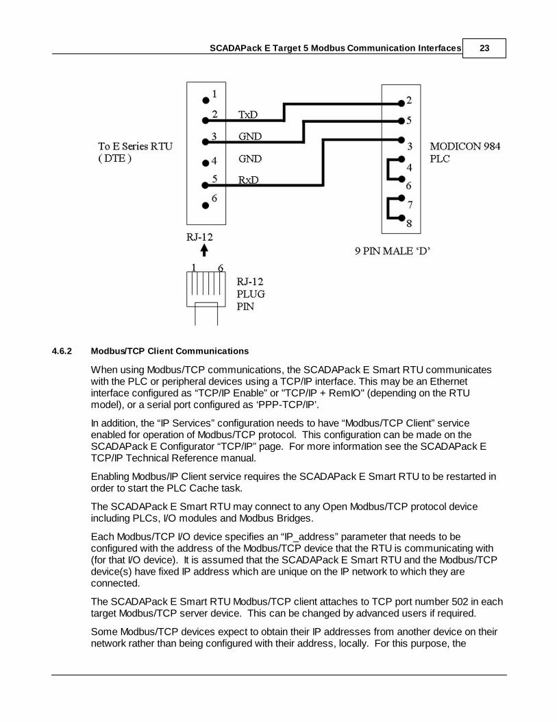
The SCADAPack E Smart RTU will not assert any hardware handshaking lines whencommunicating using RS232, RS422 or 4-wire RS485 with its Modbus PLC device driver. Ifthe Modbus PLC requires hardware handshaking (e.g. CTS asserted), it needs to be providedin the cabling to the PLC (as shown above).
When 2-wire RS485 communications is used, the SCADAPack E Smart RTU providesRS485 transmitter/receiver control internally.
A sample cable configuration for connecting a PLC to a SCADAPack ES RTU RS232 port isshown below.
22
23
24
25
SCADAPack E Target 5 Modbus Communication Interfaces 23
4.6.2 Modbus/TCP Client Communications
When using Modbus/TCP communications, the SCADAPack E Smart RTU communicateswith the PLC or peripheral devices using a TCP/IP interface. This may be an Ethernetinterface configured as “TCP/IP Enable” or "TCP/IP + RemIO" (depending on the RTUmodel), or a serial port configured as ‘PPP-TCP/IP’.
In addition, the “IP Services” configuration needs to have “Modbus/TCP Client” serviceenabled for operation of Modbus/TCP protocol. This configuration can be made on theSCADAPack E Configurator “TCP/IP” page. For more information see the SCADAPack ETCP/IP Technical Reference manual.
Enabling Modbus/IP Client service requires the SCADAPack E Smart RTU to be restarted inorder to start the PLC Cache task.
The SCADAPack E Smart RTU may connect to any Open Modbus/TCP protocol deviceincluding PLCs, I/O modules and Modbus Bridges.
Each Modbus/TCP I/O device specifies an “IP_address” parameter that needs to beconfigured with the address of the Modbus/TCP device that the RTU is communicating with(for that I/O device). It is assumed that the SCADAPack E Smart RTU and the Modbus/TCPdevice(s) have fixed IP address which are unique on the IP network to which they areconnected.
The SCADAPack E Smart RTU Modbus/TCP client attaches to TCP port number 502 in eachtarget Modbus/TCP server device. This can be changed by advanced users if required.
Some Modbus/TCP devices expect to obtain their IP addresses from another device on theirnetwork rather than being configured with their address, locally. For this purpose, the
SCADAPack E Target 5 Modbus Communication Interfaces24
SCADAPack E Smart RTU supports BOOTP Server capability. BOOTP Server needs toalso be enabled in the “IP Services” configuration to support this capability. See Section BOOTP Server Configuration for more information.
For further information on connecting to the SCADAPack E Smart RTU to TCP/IP networks,refer to the SCADAPack E TCP/IP Reference manual.
4.6.3 Modbus/TCP Server Communications
When using Modbus/TCP Server communications, the SCADAPack E Smart RTUcommunicates with Modbus/TCP clients using one of its TCP/IP interfaces. This may be theEthernet interface configured as “TCP/IP Enabled” or "TCP/IP + RemIO" (depending on theRTU model), or a serial port configured as ‘PPP-TCP/IP’.
In addition, the “IP Services” configuration needs to have “Modbus/TCP Server” serviceenabled for operation of Modbus/TCP protocol. This configuration can be made onSCADAPack E Configurator’s “TCP/IP” or "Slave / Modbus" page. For more information seethe SCADAPack E TCP/IP Technical Reference manual.
Enabling Modbus/TCP Server service requires the SCADAPack E Smart RTU to be restartedin order to start the Modbus/TCP Server listening task.
The Modbus/TCP Server ‘listens’ on TCP port number “502” for any Modbus/TCP clientdevices attempting to connect.
The Modbus/TCP server supports a maximum of concurrent clients depending on thecontroller type.
For the SCADAPack ER and SCADAPack ES controllers the Open Modbus/TCP serversupports a maximum of 20 concurrent client connections.
For the SCADAPack 300E controllers the Open Modbus/TCP server supports a maximumof 5 concurrent client connections.
An open socket will be closed if there is no activity detected for 120 seconds (see Section TCP / Operating System Issues for more information regarding the inactivity disconnecttimeout).
For further information on connecting the SCADAPack E Smart RTU to TCP/IP networks,refer to the SCADAPack E TCP/IP Reference manual.
4.6.4 Modbus RTU in TCP Client Communications
When using Modbus RTU in TCP communications, the SCADAPack E Smart RTUcommunicates with the PLC or peripheral devices using a TCP/IP interface. This may be theEthernet interface configured as “TCP/IP Enable” or "TCP/IP + RemIO" (depending on theRTU model).
In addition, the “IP Services” configuration needs to have “Modbus/IP (Client)” service enabledfor operation of Modbus RTU in TCP protocol. This configuration can be made on the
25
51
SCADAPack E Target 5 Modbus Communication Interfaces 25
SCADAPack E Configurator “TCP/IP” page. For more information see the SCADAPack ETCP/IP Technical Reference manual.
Enabling Modbus/IP (Client) service requires the SCADAPack E Smart RTU to be restarted inorder to start the PLC Cache task.
The SCADAPack E Smart RTU may connect to any Modbus RTU in TCP protocol deviceincluding PLCs, I/O modules and Modbus Bridges.
Each Modbus RTU in TCP I/O device specifies an “IP_address” parameter that needs to beconfigured with the address of the Modbus RTU in TCP device that the RTU iscommunicating with (for that I/O device). It is assumed that the SCADAPack E Smart RTUand the Modbus RTU in TCP device(s) have fixed IP address which are unique on the IPnetwork to which they are connected.
The Modbus RTU in TCP client attaches to TCP port number “49152" in each target ModbusRTU in TCP server device. (Can be changed by advanced users if required).
Some Modbus RTU in TCP devices expect to obtain their IP addresses from another deviceon their network rather than being configured with their address, locally. For this purpose, theSCADAPack E RTU supports BOOTP Server capability. BOOTP Server needs to also beenabled in the RTU’s “IP Services” configuration to support this capability. See Section BOOTP Server Configuration for more information.
For further information on connecting to the the SCADAPack E Smart RTU to TCP/IPnetworks, refer to the SCADAPack E TCP/IP Reference manual.
4.6.5 BOOTP Server Configuration
BOOTP is a TCP/IP application protocol that utilizes UDP socket communications.
The SCADAPack E Smart RTU may be configured to start a BOOTP server by selecting itfrom the SCADAPack E Configurator “TCP/IP Services” configuration.
The BOOTP server (SCADAPack E Smart RTU) listens for requests from a BOOTP client(typically an IP device on a LAN).
Typically, the BOOTP client uses its Ethernet MAC address to identify itself, and viabroadcast IP messages, requests a BOOTP server to configure its parameters.
The SCADAPack E Smart RTU is capable of configuring a BOOTP client’s “your-ip” address. However, the SCADAPack E Smart RTU will not configure any of the other BOOTP standardor extended fields. (see RFC 951 and later).
SCADAPack E Configurator provides a configuration interface for the BOOTP server. Theuser enters an Ethernet-MAC / IP address pair for each node requiring BOOTP configurationof its IP address.
The SCADAPack E Smart RTU will not answer a BOOTP request from a client node unlessthere is a corresponding entry in the Ethernet-MAC / IP address table.
25
SCADAPack E Target 5 Modbus Communication Interfaces26
Devices refer to their Ethernet-MAC address in different ways, such as “IEEE GlobalAddress”. In each case, the Ethernet-MAC address will contain a 12 digit hexadecimalnumber.
Ethernet-MAC address entry in the SCADAPack E Smart RTU, for BOOTP, may be in any ofthe following formats (12 hexadecimal digits, case insensitive):
00:1A:2B:3C:4D:5E
00-1A-2B-3C-4D-5E
001A2B3C4D5E
IP address entry needs to be in the following format (leading zeroes not required):192.168.1.97
Configuring BOOTP with SCADAPack E Configurator
Configuring BOOTP from the Command Line
4.6.5.1 Configuring BOOTP with SCADAPack E Configurator
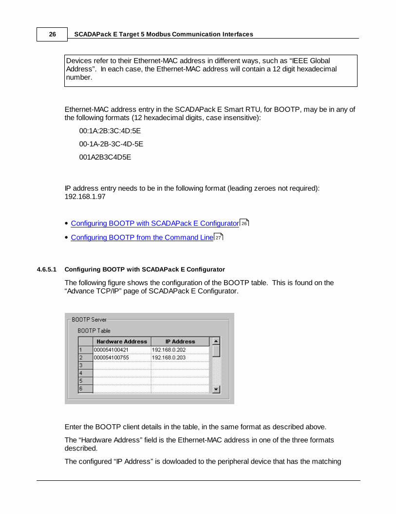
The following figure shows the configuration of the BOOTP table. This is found on the“Advance TCP/IP” page of SCADAPack E Configurator.
Enter the BOOTP client details in the table, in the same format as described above.
The “Hardware Address” field is the Ethernet-MAC address in one of the three formatsdescribed.
The configured “IP Address” is dowloaded to the peripheral device that has the matching
26
27
SCADAPack E Target 5 Modbus Communication Interfaces 27
hardware address.
Changes to the BOOTP Table in SCADAPack E Configurator should be followed by “WriteRTU Configuration”.
BOOTP Table changes become active in the SCADAPack E RTU immediately (i.e. no needto restart the RTU).
4.6.5.2 Configuring BOOTP from the Command Line
In addition to configuring the BOOTP table via SCADAPack E Configurator, the SCADAPackE Smart RTU command line provides a management command to manipulate the BOOTPserver configuration table.
C:\> bootp /?BOOTP protocol loads IP address to remote Ethernet devicesBOOTP command manipulates configuration table(changes ARE permanent)Usage:BOOTP PRINTBOOTP ADD remote-MAC remote-IPBOOTP DELETE [remote-MAC]
[remote-IP]
For example, the following command prints the BOOTP configuration table:
C:\> bootp print
BOOTP entries:
Ethernet MAC Addr IP Addr Loaded Load Count
00-01-02-03-04-05 192.168.0.242 1
01-02-03-04-05-06 158.234.186.168 2
This indicates the configured BOOTP server entries (what IP Address will be loaded to whichEthernet MAC address), and indicates how many times the BOOTP server has sent BOOTPresponse commands to the appropriate BOOTP client.
The following command ADDS or REPLACES an entry in the BOOTP configuration table:
C:\> bootp add 01-02-03-04-AA-BB 158.234.186.168
An existing entry with a matching Ethernet MAC address OR matching IP address will bereplaced by the new entry. This is typically used if an existing Modbus/TCP or Modbus RTU
SCADAPack E Target 5 Modbus Communication Interfaces28
in TCP device is replaced by another device with a different Ethernet MAC Addr, for example.
The following command REMOVES an entry in the BOOTP configuration table:
C:\> bootp del 01-02-03-04-AA-BB
Either the Ethernet-MAC address or IP address may be used to specify which BOOTP entryto remove, but the string used in the “del” command needs to exactly match the string in theBOOTP entry in order for the entry to be removed successfully.
Changes made to the BOOTP configuration table via SCADAPack E Configurator orcommand line are retained in NON-VOLATILE MEMORY not requiring the SCADAPack ESmart RTU to be restarted in order to take effect. However, remember to make a record ofthe configuration after they are modified.
When BOOTP diagnostics are enabled (via TCPDIAG command), the SCADAPack E SmartRTU diagnostic stream indicates when a remote device is configured via BOOTP by theRTU. E.g.
BOOTP>>loaded IP: 158.234.186.168 to MAC: 01-02-03-04-AA-BB
4.7 System Points
System points are provided to indicate the status of some I/O Devices that are used for SlaveI/O communications with peripheral devices such as PLCs.
Where multiple Slave I/O Devices are present in an IEC 61131-3 Resource , consecutive,sequential system point pairs are used for the next Slave I/O device, regardless of what PLCport the devices are connected to. Each Resource is allocated a separate set of systempoints for Slave I/O Devices.
The status for the Slave I/O Devices reported (according to the above rules) has two systempoints associated with it. The communications status, and the data cache time.
The communication status indicates the status of the communication with the PLC for thedata on the I/O device. For more information see Section Modbus Status Values .
The age of the cached data for a slave Input devices is stored in the cache time system pointfor that device. For more information see Section Data Cache Time .
A separate RTU system point is provided to set the background update rate of PLC Outputdevices. For more information see Section PLC Output device Default Background UpdateRate .
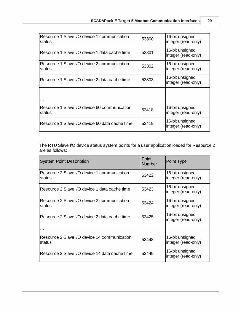
The RTU Slave I/O device status system points for a user application loaded for Resource 1are as follows:
System Point DescriptionPointNumber
Point Type
30
49
31
SCADAPack E Target 5 Modbus Communication Interfaces 29
Resource 1 Slave I/O device 1 communicationstatus
5330016-bit unsignedinteger (read-only)
Resource 1 Slave I/O device 1 data cache time 5330116-bit unsignedinteger (read-only)
Resource 1 Slave I/O device 2 communicationstatus
5330216-bit unsignedinteger (read-only)
Resource 1 Slave I/O device 2 data cache time 5330316-bit unsignedinteger (read-only)
…
Resource 1 Slave I/O device 60 communicationstatus
5341816-bit unsignedinteger (read-only)
Resource 1 Slave I/O device 60 data cache time 5341916-bit unsignedinteger (read-only)
The RTU Slave I/O device status system points for a user application loaded for Resource 2are as follows:
System Point DescriptionPointNumber
Point Type
Resource 2 Slave I/O device 1 communicationstatus
5342216-bit unsignedinteger (read-only)
Resource 2 Slave I/O device 1 data cache time 5342316-bit unsignedinteger (read-only)
Resource 2 Slave I/O device 2 communicationstatus
5342416-bit unsignedinteger (read-only)
Resource 2 Slave I/O device 2 data cache time 5342516-bit unsignedinteger (read-only)
…
Resource 2 Slave I/O device 14 communicationstatus
5344816-bit unsignedinteger (read-only)
Resource 2 Slave I/O device 14 data cache time 5344916-bit unsignedinteger (read-only)
SCADAPack E Target 5 Modbus Communication Interfaces30
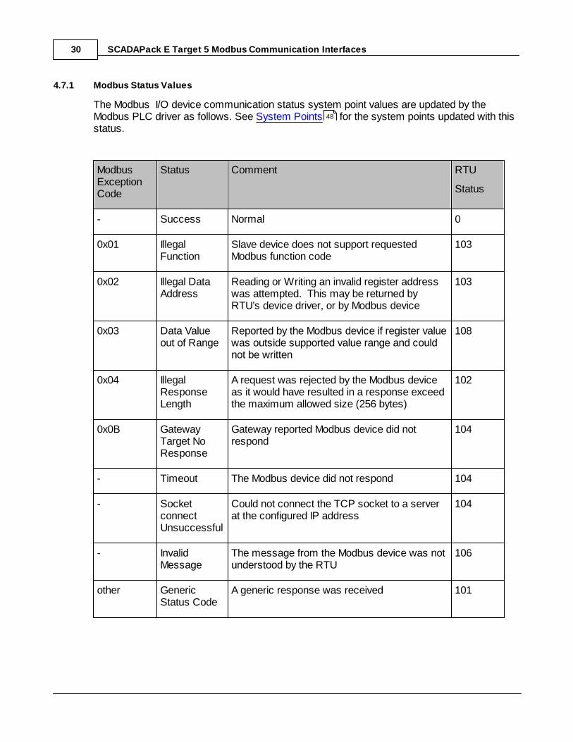
4.7.1 Modbus Status Values
The Modbus I/O device communication status system point values are updated by theModbus PLC driver as follows. See System Points for the system points updated with thisstatus.
ModbusExceptionCode
Status Comment RTU
Status
- Success Normal 0
0x01 IllegalFunction
Slave device does not support requestedModbus function code
103
0x02 Illegal DataAddress
Reading or Writing an invalid register addresswas attempted. This may be returned byRTU’s device driver, or by Modbus device
103
0x03 Data Valueout of Range
Reported by the Modbus device if register valuewas outside supported value range and couldnot be written
108
0x04 IllegalResponseLength
A request was rejected by the Modbus deviceas it would have resulted in a response exceedthe maximum allowed size (256 bytes)
102
0x0B GatewayTarget NoResponse
Gateway reported Modbus device did notrespond
104
- Timeout The Modbus device did not respond 104
- SocketconnectUnsuccessful
Could not connect the TCP socket to a serverat the configured IP address
104
- InvalidMessage
The message from the Modbus device was notunderstood by the RTU
106
other GenericStatus Code
A generic response was received 101
48
SCADAPack E Target 5 Modbus Communication Interfaces 31
4.7.2 Data Cache Time
The age of the data in the RTU cache for Modbus PLC and Modbus/TCP Input device data ispresented in data ‘Cache Time’ system points. The cache time is initialized to zero when theIEC 61131-3 Resource starts and increases until a successful read occurs, after which timethe value is reset to zero.
The system point corresponding to a PLC Device input device may be used by the Resourceto determine the suitability of using the input data from the input device. (I.e. if the value is toohigh, then the data is stale and the Resource may choose not to use it).
Each Input device has its own data cache time system point. The data cache time systempoints for Output devices will indicate zero.
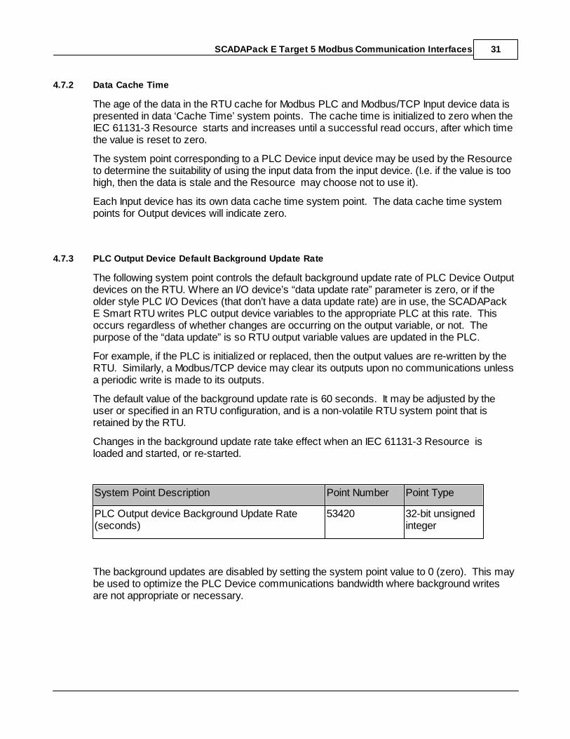
4.7.3 PLC Output Device Default Background Update Rate
The following system point controls the default background update rate of PLC Device Outputdevices on the RTU. Where an I/O device’s “data update rate” parameter is zero, or if theolder style PLC I/O Devices (that don’t have a data update rate) are in use, the SCADAPackE Smart RTU writes PLC output device variables to the appropriate PLC at this rate. Thisoccurs regardless of whether changes are occurring on the output variable, or not. Thepurpose of the “data update” is so RTU output variable values are updated in the PLC.
For example, if the PLC is initialized or replaced, then the output values are re-written by theRTU. Similarly, a Modbus/TCP device may clear its outputs upon no communications unlessa periodic write is made to its outputs.
The default value of the background update rate is 60 seconds. It may be adjusted by theuser or specified in an RTU configuration, and is a non-volatile RTU system point that isretained by the RTU.
Changes in the background update rate take effect when an IEC 61131-3 Resource isloaded and started, or re-started.
System Point Description Point Number Point Type
PLC Output device Background Update Rate(seconds)
53420 32-bit unsignedinteger
The background updates are disabled by setting the system point value to 0 (zero). This maybe used to optimize the PLC Device communications bandwidth where background writesare not appropriate or necessary.
SCADAPack E Target 5 Modbus Communication Interfaces32
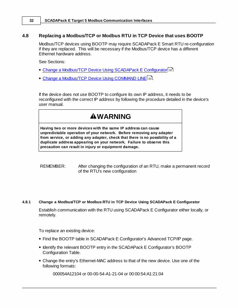
4.8 Replacing a Modbus/TCP or Modbus RTU in TCP Device that uses BOOTP
Modbus/TCP devices using BOOTP may require SCADAPack E Smart RTU re-configurationif they are replaced. This will be necessary if the Modbus/TCP device has a differentEthernet hardware address.
See Sections:
Change a Modbus/TCP Device Using SCADAPack E Configurator
Change a Modbus/TCP Device Using COMMAND LINE .
If the device does not use BOOTP to configure its own IP address, it needs to bereconfigured with the correct IP address by following the procedure detailed in the device’suser manual.
WARNING
Having two or more devices with the same IP address can causeunpredictable operation of your network. Before removing any adapterfrom service, or adding any adapter, check that there is no possibility of aduplicate address appearing on your network. Failure to observe thisprecaution can result in injury or equipment damage.
REMEMBER: After changing the configuration of an RTU, make a permanent recordof the RTU’s new configuration
4.8.1 Change a Modbus/TCP or Modbus RTU in TCP Device Using SCADAPack E Configurator
Establish communication with the RTU using SCADAPack E Configurator either locally, orremotely.
To replace an existing device:
Find the BOOTP table in SCADAPack E Configurator's Advanced TCP/IP page.
Identify the relevant BOOTP entry in the SCADAPack E Configurator’s BOOTPConfiguration Table.
Change the entry’s Ethernet-MAC address to that of the new device. Use one of thefollowing formats:
000054A12104 or 00-00-54-A1-21-04 or 00:00:54:A1:21:04
32
33
SCADAPack E Target 5 Modbus Communication Interfaces 33
Write the configuration to the RTU. The BOOTP entry is now active.
Connect the new device to the network & power it up.
To add a new device:
Choose the first free BOOTP entry in the SCADAPack E Configurator’s BOOTPConfiguration Table.
Add the new device’s Ethernet-MAC address to the table. Use one of the following formats:
000054A12104 or 00-00-54-A1-21-04 or 00:00:54:A1:21:04
Add the desired IP address for the entry.
Write the configuration to the RTU. The BOOTP entry is now active.
Connect the new device to the network & power it up.
4.8.2 Change a Modbus/TCP or Modbus RTU in TCP Device Using COMMAND LINE
Change a Modbus/TCP Device Using COMMAND LINE
The SCADAPack E Smart RTU command line is available:
Using Telnet, when enabled on the RTU
Using a terminal program plugged into an RTU (e.g. the DIAG port)
Using a terminal program plugged into an RTU’s port, and by pressing<Enter><Enter><Enter>
The command line can be use to replace an existing Modbus/TCP device BOOTP entry, oradd a new Modbus/TCP device BOOTP entry. This is only applicable for devices that useBOOTP as a means of configuring their IP addresses.
If you are replacing an existing device you will need to know the IP address being used by theold device. You will also need to know the new device’s Ethernet-MAC address (12-digithexadecimal number).
If you are adding a new BOOTP entry, you will need to know the desired IP address for thenew device as well as its Ethernet-MAC address.
You can check configured BOOTP entries by using the command:
bootp print
From the SCADAPack E RTU command line, enter the following command to add or changea BOOTP entry:
SCADAPack E Target 5 Modbus Communication Interfaces34
bootp add Ethernet-MAC-addr IP-address
For example: bootp add 01020304AABB 158.234.186.168
You can re-check the changed BOOTP entries by using:
bootp print
Check BOOTP Diagnostics
You can check BOOTP operation with a new device by performing the following procedures:
Enable BOOTP diagnostics & enter diagnostic mode with the commands:
tcpdiag enable BOOTP <enter>diag
Connect the new device to the network & power it up. When the new device sends a BOOTP request for an IP address, the SCADAPack E Smart RTU should display something similar to:
BOOTP>>loaded IP: 158.234.186.168 to MAC: 01020304AABB
Communication may also be verified by issuing a PING command. For example:
ping 158.234.186.168
5 Modbus Slave/Server Operation
The following sections detail SCADAPack E Smart RTU communication where the RTU is aModbus Slave and Modbus/TCP Server.
Setting up Modbus Slave / Server
Modbus Slave and Modbus /TCP Server Implementation Conditions
System Points
Diagnostics
5.1 Setting up Modbus Slave / Server
The following sections document the conditions specific to the native Modbus Slave / Serverdriver.
Conditions common to the Modbus/TCP Server and the Modbus serial Slave such asconformance classes, mapping of Modbus addresses to the RTU point address space, andthe circumstances under which specific response exception codes are generated, aredetailed in Section Modbus/TCP Server and Modbus Slave Implementation Conditions .
The SCADAPack E Smart RTU supports a native Modbus Slave driver which responds to
34
35
48
50
35
SCADAPack E Target 5 Modbus Communication Interfaces 35
Modbus requests by accessing RTU point data directly.
The Modbus Slave driver is only operational if at least one serial port function is set toModbus Slave or if Modbus/TCP (Server) is enabled as part of the RTU TCP/IP Servicesselection. The RTU needs to be restarted to activate a port mode or TCP Services change.
Modbus Slave communications can be independently enabled on multiple serial ports, thoughthe single Slave Address is applied to each instance of the Modbus Slave driver (see Section Modbus Slave Address for details regarding Modbus Slave configuration system points).
Multiple Modbus/TCP server communications sessions are supported (up to 5), though thesingle Modbus Unit Identifier is applied to each Modbus/TCP connection. Also see section Modbus/TCP Server Unit Identifier .
5.2 Modbus Slave and Modbus /TCP Server Implementation Conditions
This following sections detail implementation conditions that are common to both theModbus/TCP Server and the native Modbus Slave:
Conformance Classes and Function Codes 7 & 8
Modbus Address Mapping to RTU Point Address Space
Exception Codes
Open Modbus/TCP Server
The SCADAPack E Smart RTU Modbus/TCP server is only operational if the “IP Services”configuration has the “Modbus/TCP Server” service enabled.
This configuration can be made from the SCADAPack E Configurator “TCP/IP” page or"Slave / Modbus" page.
5.2.1 Conformance Classes & Supported Function Codes
Conformance Classes
The following Modbus conformance classes (and function codes) are supported by theModbus/TCP Server and the native Modbus Slave.
Class 0 (function codes 3 and 16)
Class 1 (function codes 1, 2, 4, 5, 6, and 7)
Class 2 (function code 15 only).
49
49
35
36
47
SCADAPack E Target 5 Modbus Communication Interfaces36
Function Code 7
This function code allows a client to request the Modbus server/slave to return an exceptionstatus that is stored in a pre-determined range of 8 coils. RTU binary system (scratchpad)points 50000 to 50007 are allocated for this purpose.
RTU binary point 50000 will map to the least significant bit of the response byte.
RTU binary point 50007 will map to the most significant bit of the response byte.
Function Code 8
This function code allows a client to request the Modbus slave to return a response to a"Return Query Data" request. The following functionality is provided:
Function Code 8 is supported on Modbus Slave serial connections only
A Function Code 8 request on a Modbus/TCP connection returns Exception response withexception code 1 (Illegal function)
Sub function 00 00 is the only sub function supported for a Modbus function code 8 request
A response will only be generated to a FC8 Sub-function 00 00 request when the data fieldsize is 2
The Response to a FC8 Sub-function 00 00 (data field size 2) request is an echo of therequest
A request for Sub functions other than 00 00 returns an Exception response with exceptioncode 3 (Illegal Data Value)
There will be no response to a FC8 Sub-function 00 00 request if the data field size is not 2
5.2.2 Modbus Address Mapping to RTU Point Address Space
This section identifies how the binary and analog Modbus addresses are mapped to the RTUpoint address space.
The “Modbus address” referenced in this section refers to the Modicon PLC equivalentregister address i.e. "protocol address" + 1. The "protocol address" is also referred to as the"reference address".
Modbus Slave / Server register addresses are mapped directly to the SCADAPack E SmartRTU database point number in a one to one relationship
Modbus input register types map to RTU Physical Input point types and RTU Derived pointtypes
Modbus output register types map to RTU Physical Output point types and RTU Derived
SCADAPack E Target 5 Modbus Communication Interfaces 37
point types
The points used by the DATA CONCENTRATOR are converted to Physical point typesautomatically, according to their protocol data type (e.g. DNP3 Static Object Type). Modbus register types map to Data Concentrator points using the same rules asRTU Physical point types. Take care to use the appropriate Modbus request to access theappropriate physical point type.
For more information see Binary Addresses and Analog Addresses sections
The data format presented to Modbus is dependent on the DNP3 Static Object Typeattribute of the RTU point configuration
For analog multiple read/writes, this mapping is relevant for the start address only. Themapping of subsequent registers to RTU points is dependent on the RTU configuration pointDNP static object types (e.g 16-bit, 32-bit and floating point object types).
As a result of these mapping rules, it is possible to reference a different 32-bit analog point inthe RTU with the same Modbus register, based on different reference numbers and wordcounts of separate Modbus requests.
Section Modbus Register / 32-bit Analog Point Mapping Configuration discusses therequired configurations for consistent and deterministic mapping of Modbus registers to 32-bitanalog points.
See Sections Reading Analog Registers and Writing Analog Registers for moreinformation on function codes that reference analog points.
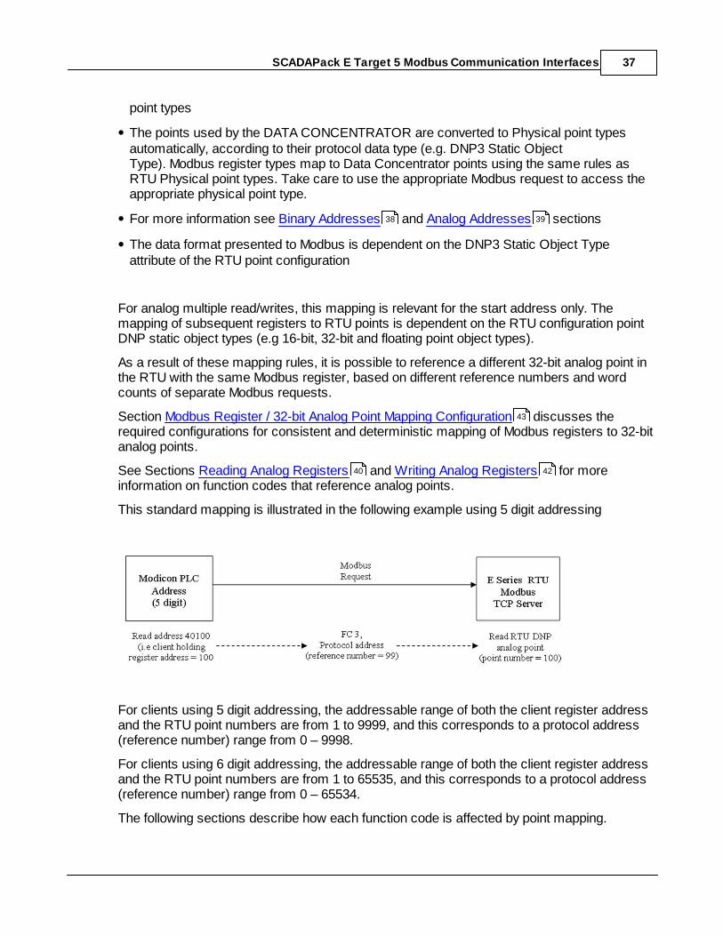
This standard mapping is illustrated in the following example using 5 digit addressing
For clients using 5 digit addressing, the addressable range of both the client register addressand the RTU point numbers are from 1 to 9999, and this corresponds to a protocol address(reference number) range from 0 – 9998.
For clients using 6 digit addressing, the addressable range of both the client register addressand the RTU point numbers are from 1 to 65535, and this corresponds to a protocol address(reference number) range from 0 – 65534.
The following sections describe how each function code is affected by point mapping.
38 39
43
40 42
SCADAPack E Target 5 Modbus Communication Interfaces38
See Section Exception Codes for information on how multiple read / write requests arehandled when some of the requested addresses are invalid.
Binary Addresses
Analog Addresses
5.2.2.1 Binary Addresses
RTU database binary point data is provided to the Modbus serial Slave and Modbus/TCPserver in IEC_DISCRETE format. For more information refer to Modbus PLC Data Types .
The following information is applicable to the next sections for Function Code 1 and 2 readsand Function Code 5 and 15 writes:
when "x" is referenced it means Modbus Address = x
NONE of the requested points exist if for every modbus address x referenced in therequest, no RTU configuration point x exists.
Function Code 1: Read Discrete Coils
FC 1 will invoke point reads for every Modbus address x referenced in the request, describedas follows …
if NONE of the requested points exist then return ILLEGAL FUNCTION (01)
if x exists as a Physical Out binary point or a Derived binary point then the current value ofpoint x will be read
The Data Concentrator converts Derived binary points that present as DNP3 binary outputobjects into Physical Out binary points
if at least one of the points in the Modbus request does exist, and point x does NOT exist,then a zero value will be returned in the response for Modbus register x
Function Code 2: Read Discrete Inputs
FC 2 will invoke point reads for every modbus address x referenced in the request, describedas follows …
if NONE of the requested points exist then this returns ILLEGAL FUNCTION (01)
if x exists as a Physical In binary point or a Derived binary point then the current value ofpoint x will be read
The Data Concentrator converts Derived binary points that present as DNP3 binary inputobjects into Physical In binary points
if at least one of the points in the Modbus request does exist, and point x does NOT exist,
47
38
39
20
SCADAPack E Target 5 Modbus Communication Interfaces 39
then a zero value will be returned in the response for Modbus register x
Function Code 5: Preset Discrete Coil
FC 5 will invoke point writes, described as follows …
if x exists as a Physical Out binary point or a Derived binary point then point x will becontrolled
The Data Concentrator converts Derived binary points that present as DNP3 binary outputobjects into Physical Out binary points
if point x does NOT exist then this returns ILLEGAL FUNCTION (01)
Function Code 15: Write Multiple Coils
FC 15 will invoke point writes for every modbus address x referenced in the request,described as follows …
if x exists as a Physical Out binary point or a Derived binary point then point x will becontrolled
The Data Concentrator converts Derived binary points that present as DNP3 binary outputobjects into Physical Out binary points
if x does NOT exist as a binary output point then stop processing request and returnILLEGAL FUNCTION (01)
5.2.2.2 Analog Addresses
This section details the specific mapping for function codes that reference analogaddresses.
As noted earlier, it is possible for mixed 16-bit and 32-bit Modbus data value's registermapping to be inconsistent where Modbus registers map to RTU points configured in 32-bitvalue format. Section Modbus Register / 32-bit Analog Point Mapping Configurationdemonstrates the configurations required for consistent mapping of Modbus registers to 32-bit analog points.
The data types returned in Modbus responses are influenced by the configuration of the DNPStatic Object Type in each database analog point configuration.
Analog Point Configuration:
DNP3 Static Object Type
Modbus Response:
Number of Registers Modbus data type
g30 v1 32-bit Analog In
g30 v3 32-bit Analog In NoFlags
2
IEC DINT
(signed 32-bitinteger)
43
SCADAPack E Target 5 Modbus Communication Interfaces40
g20 v1 32-bit Counter
g20 v5 32-bit Counter NoFlags
2
IEC UDINT
(unsigned 32-bitinteger)
g30 v5 Short Floating Point
(Engineering value) 2
IEC REAL
(32-bit floating point)
g30 v2 16-bit Analog In
g30 v4 16-bit Analog In NoFlags
1
IEC INT
(signed 16-bitinteger)
g20 v2 16-bit Counter
g20 v6 16-bit Counter NoFlags
1
IEC UINT
(unsigned 16-bitinteger)
For more information refer to Modbus PLC Data Types .
The following information is applicable to the next sections for Function Code 3 and 4 readsand Function Code 6 and 16 writes:
when "x" is referenced it means modbus address = x
corresponding analog database point = y (depends on DNP static object type of point. Ifpoints referenced are “16 bit analogs” then y = x)
"NONE of the requested points exist" means that for every modbus address x referenced inthe request, no RTU configuration point y exists.
See the following sections for descriptions of individual Modbus function codes and howModbus register requests map to point types:
Reading Analog Registers
Writing Analog Registers
5.2.2.2.1 Reading Analog Registers
Function Code 3: Read Holding Registers
FC 3 will invoke point reads for every modbus address x referenced in the request, describedas follows …
if NONE of the requested points exist then return ILLEGAL FUNCTION (01)
if y exists as a Physical Out analog point or a Derived analog point then the current value of
20
40
42
SCADAPack E Target 5 Modbus Communication Interfaces 41
point y will be read
The Data Concentrator converts Derived analogs points that present as DNP3 analogoutput objects into Physical Out analog points
if at least one of the points in the Modbus request does exist, and point y does NOT exist,then a zero value will be returned in the response for Modbus register x
Function Code 4: Read Input Registers
FC 4 will invoke point reads for every modbus address x referenced in the request, describedas follows …
if NONE of the requested points exist then return ILLEGAL FUNCTION (01)
if y exists as a Physical In analog point or a Derived analog point then the current value ofpoint y will be read
The Data Concentrator converts Derived analogs points that present as DNP3 analog inputobjects into Physical In analog points
if at least one of the points in the Modbus request does exist, and point y does NOT exist,then a zero value will be returned in the response for Modbus register x
Reading Multiple Registers
The register address to RTU database point mapping described in this section relatesprimarily to the start register address specified in the Modbus request.
The word count included in the request, in conjunction with the DNP static object type of themapped points, will affect the number of RTU database points included in the response.
The following example illustrates this mapping for function code 3:
Consider the Modbus request as follows (starting from the function code)
… 03 03 e8 00 03
which translates to …”read 3 holding registers at protocol reference number 1000” (41001 inModicon style register addressing).
The protocol reference number 1000 would therefore map to RTU point number 1001.
Consider the following RTU points configurations:
RTU Analog Point 1001 : DNP static object type 16 bit analog
SCADAPack E Target 5 Modbus Communication Interfaces42
RTU Analog Point 1002 : DNP static object type 32 bit analog
RTU Analog Point 1003 : DNP static object type 16 bit analog …
This would map RTU analog points to Modbus client holding register addresses as follows
RTU Analog point 1001 maps to client holding register address 1001
RTU Analog point 1002 maps to client holding register addresses 1002 and 1003.
RTU Analog point 1003 would not be included in the response as it exceeds the registerlength requested.
The same functionality applies for function code 3 and 4.
See Modbus Register / 32-bit Analog Point Mapping Configuration for more information onhandling more complex combinations of 16 and 32 bit registers.
5.2.2.2.2 Writing Analog Registers
Function Code 6: Write Single Register
FC 6 and FC 16 will invoke point writes for every modbus address x referenced in therequest, described as follows …
if y exists in the SCADAPack E RTU as a Physical Out analog point or a Derived analogpoint then point y will be controlled
if point y does NOT exist as a Physical Out analog point or a Derived analog point thenprocessing is stopped ILLEGAL FUNCTION (01) is returned
Function Code 16: Write Multiple Registers
if y exists in the SCADAPack E RTU as a Physical Out analog point or a Derived analogpoint then point y will be controlled
if point y does NOT exist as a Physical Out analog point or a Derived analog point thenprocessing is stopped ILLEGAL FUNCTION (01) is returned
Writing Multiple Registers
The register address point mapping described above for function code 16, relates primarilyto the start register address specified in the modbus request. The word count included in therequest, in conjunction with the DNP static object type of the mapped points, will affect the
43
SCADAPack E Target 5 Modbus Communication Interfaces 43
number of RTU points controlled by the request. The following example illustrates thismapping.
Consider the modbus request as follows (starting from the function code)
… 10 03 e8 00 03 06 00 08 00 04 00 00
which translates to …”write 3 holding registers at protocol reference number 1000” (41001 inModicon style register addressing).
The protocol reference number 1000 would therefore map to RTU point number 1001. Consider the following RTU points configurations:
RTU Analog point 1001 : DNP static object type 16 bit analog
RTU Analog point 1002 : DNP static object type 32 bit analog
RTU Analog point 1003 : DNP static object type 16 bit analog …
The Modbus request would result in the following controls :
RTU Analog point 1001 is assigned the integer value 8
RTU Analog point 1002 is assigned the integer value 4.
RTU Analog point 1003 is not controlled as the point is outside the register range of theModbus write request.
See Modbus Register / 32-bit Analog Point Mapping Configuration for more information onhandling more complex combinations of 16 and 32 bit registers.
5.2.2.3 Modbus Register / 32-bit Analog Point Mapping Configuration
As noted earlier, it is possible to reference a different 32-bit analog point in the RTU with thesame modbus register, based on different reference numbers and word counts of separatemodbus requests.
For a consistent and deterministic mapping for 32-bit values point values to Modbus registersfor the Modbus/TCP Server and the native Modbus Slave, use the Modbus Register / 32-bitAnalog Point Map table on the SCADAPack E Configurator Slave | Modbus page.
TIP: Add RTU points to this table when you want to access them as 32-bit Modbusregisters. (e.g. Long Integers, Short Floating Point values, etc.)
It is strongly recommended that points are allocated consecutively so that the registermapping is grouped together in a single entry in the table. The Point Quantity field indicateshow many consecutive points will be read or written as 32-bit Modbus registers.
Points accessed as 16-bit Modbus registers should NOT be added to this table.
43

SCADAPack E Target 5 Modbus Communication Interfaces44
The following image displays the SCADAPack E Configurator interface, which show anexample for RTU analog points 1001-1004 as writeable 32-bit Modbus holding registers.
This configuration would result in the consistent register / point mapping as shown in thefollowing diagram, irrespective of the protocol reference number (register address) and theword count specified in a Modbus request.
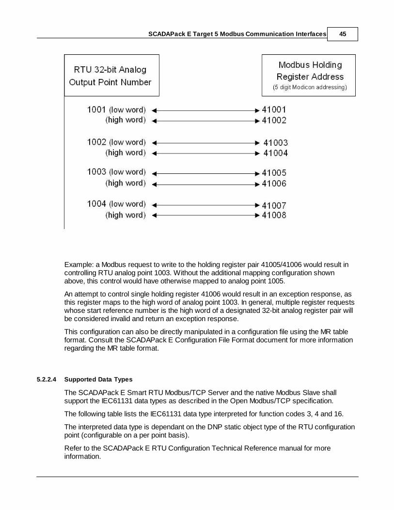
SCADAPack E Target 5 Modbus Communication Interfaces 45
Example: a Modbus request to write to the holding register pair 41005/41006 would result incontrolling RTU analog point 1003. Without the additional mapping configuration shownabove, this control would have otherwise mapped to analog point 1005.
An attempt to control single holding register 41006 would result in an exception response, asthis register maps to the high word of analog point 1003. In general, multiple register requestswhose start reference number is the high word of a designated 32-bit analog register pair willbe considered invalid and return an exception response.
This configuration can also be directly manipulated in a configuration file using the MR tableformat. Consult the SCADAPack E Configuration File Format document for more informationregarding the MR table format.
5.2.2.4 Supported Data Types
The SCADAPack E Smart RTU Modbus/TCP Server and the native Modbus Slave shallsupport the IEC61131 data types as described in the Open Modbus/TCP specification.
The following table lists the IEC61131 data type interpreted for function codes 3, 4 and 16.
The interpreted data type is dependant on the DNP static object type of the RTU configurationpoint (configurable on a per point basis).
Refer to the SCADAPack E RTU Configuration Technical Reference manual for moreinformation.
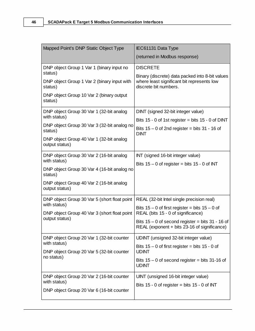
SCADAPack E Target 5 Modbus Communication Interfaces46
Mapped Point's DNP Static Object Type IEC61131 Data Type
(returned in Modbus response)
DNP object Group 1 Var 1 (binary input nostatus)
DNP object Group 1 Var 2 (binary input withstatus)
DNP object Group 10 Var 2 (binary outputstatus)
DISCRETE
Binary (discrete) data packed into 8-bit valueswhere least significant bit represents lowdiscrete bit numbers.
DNP object Group 30 Var 1 (32-bit analogwith status)
DNP object Group 30 Var 3 (32-bit analog nostatus)
DNP object Group 40 Var 1 (32-bit analogoutput status)
DINT (signed 32-bit integer value)
Bits 15 - 0 of 1st register = bits 15 - 0 of DINT
Bits 15 – 0 of 2nd register = bits 31 - 16 ofDINT
DNP object Group 30 Var 2 (16-bit analogwith status)
DNP object Group 30 Var 4 (16-bit analog nostatus)
DNP object Group 40 Var 2 (16-bit analogoutput status)
INT (signed 16-bit integer value)
Bits 15 – 0 of register = bits 15 - 0 of INT
DNP object Group 30 Var 5 (short float pointwith status)
DNP object Group 40 Var 3 (short float pointoutput status)
REAL (32-bit Intel single precision real)
Bits 15 – 0 of first register = bits 15 – 0 ofREAL (bits 15 - 0 of significance)
Bits 15 – 0 of second register = bits 31 - 16 ofREAL (exponent + bits 23-16 of significance)
DNP object Group 20 Var 1 (32-bit counterwith status)
DNP object Group 20 Var 5 (32-bit counterno status)
UDINT (unsigned 32-bit integer value)
Bits 15 – 0 of first register = bits 15 - 0 ofUDINT
Bits 15 – 0 of second register = bits 31-16 ofUDINT
DNP object Group 20 Var 2 (16-bit counterwith status)
DNP object Group 20 Var 6 (16-bit counter
UINT (unsigned 16-bit integer value)
Bits 15 - 0 of register = bits 15 - 0 of INT
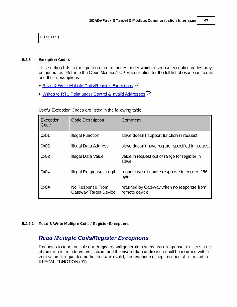
SCADAPack E Target 5 Modbus Communication Interfaces 47
no status)
5.2.3 Exception Codes
This section lists some specific circumstances under which response exception codes maybe generated. Refer to the Open Modbus/TCP Specification for the full list of exception codesand their descriptions:
Read & Write Multiple Coils/Register Exceptions
Writes to RTU Point under Control & Invalid Addresses
Useful Exception Codes are listed in the following table:
ExceptionCode
Code Description Comment
0x01 Illegal Function slave doesn’t support function in request
0x02 Illegal Data Address slave doesn’t have register specified in request
0x03 Illegal Data Value value in request out of range for register inslave
0x04 Illegal Response Length request would cause response to exceed 256bytes
0x0A No Response FromGateway Target Device
returned by Gateway when no response fromremote device
5.2.3.1 Read & Write Multiple Coils / Register Exceptions
Read Multiple Coils/Register Exceptions
Requests to read multiple coils/registers will generate a successful response, if at least oneof the requested addresses is valid, and the invalid data addresses shall be returned with azero value. If requested addresses are invalid, the response exception code shall be set toILLEGAL FUNCTION (01).
47
48
SCADAPack E Target 5 Modbus Communication Interfaces48
Write Multiple Coils/Register Exceptions
Requests to write to multiple coils/registers may generate a successful response only if therequested addresses are valid and controls succeed. If at least one of the requestedaddresses is invalid or a control does not succeed then the remaining controls in the requestare ignored and an exception response is returned with exception code ILLEGAL FUNCTION(01).
5.2.3.2 Exceptions Writing to RTU Points
Writes to RTU Points under Control
Any requests to write to coils / registers that may be under the exclusive control of the RTUsequencer (ISaGRAF), will generate the response exception code ILLEGAL FUNCTION (01)even if previous controls in the same multiple write request have been successful. Readrequests to points under control will be successful.
Invalid Addresses
Any requests that reference RTU point numbers outside of the range 0-65535 will generatethe response exception code ILLEGAL DATA ADDRESS (02). See Section Modbus AddressMapping to RTU Point Address Space for details on how Modbus addresses map to RTUpoint numbers.
Bad Point Quality
Any requests that write to an RTU point that has bad quality (e.g. Point OperationUnsuccessful quality) will update the point in the RTU database, but generate an exceptionresponse with exception code ILLEGAL FUNCTION (01).
5.3 System Points
RTU system points are provided for configuration of Modbus communication parameters.
Modbus/TCP Server Unit Identifier
Modbus Slave Address
36
49
49
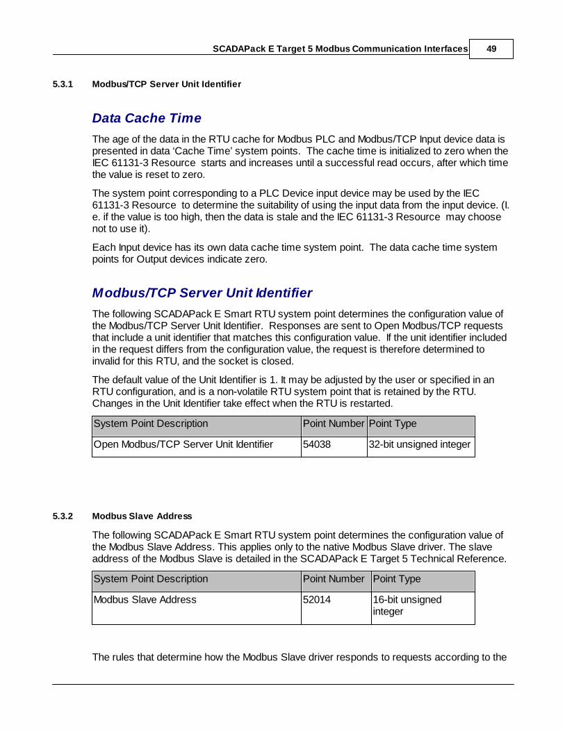
SCADAPack E Target 5 Modbus Communication Interfaces 49
5.3.1 Modbus/TCP Server Unit Identifier
Data Cache Time
The age of the data in the RTU cache for Modbus PLC and Modbus/TCP Input device data ispresented in data ‘Cache Time’ system points. The cache time is initialized to zero when theIEC 61131-3 Resource starts and increases until a successful read occurs, after which timethe value is reset to zero.
The system point corresponding to a PLC Device input device may be used by the IEC61131-3 Resource to determine the suitability of using the input data from the input device. (I.e. if the value is too high, then the data is stale and the IEC 61131-3 Resource may choosenot to use it).
Each Input device has its own data cache time system point. The data cache time systempoints for Output devices indicate zero.
Modbus/TCP Server Unit Identifier
The following SCADAPack E Smart RTU system point determines the configuration value ofthe Modbus/TCP Server Unit Identifier. Responses are sent to Open Modbus/TCP requeststhat include a unit identifier that matches this configuration value. If the unit identifier includedin the request differs from the configuration value, the request is therefore determined toinvalid for this RTU, and the socket is closed.
The default value of the Unit Identifier is 1. It may be adjusted by the user or specified in anRTU configuration, and is a non-volatile RTU system point that is retained by the RTU.Changes in the Unit Identifier take effect when the RTU is restarted.
System Point Description Point Number Point Type
Open Modbus/TCP Server Unit Identifier 54038 32-bit unsigned integer
5.3.2 Modbus Slave Address
The following SCADAPack E Smart RTU system point determines the configuration value ofthe Modbus Slave Address. This applies only to the native Modbus Slave driver. The slaveaddress of the Modbus Slave is detailed in the SCADAPack E Target 5 Technical Reference.
System Point Description Point Number Point Type
Modbus Slave Address 52014 16-bit unsignedinteger
The rules that determine how the Modbus Slave driver responds to requests according to the
SCADAPack E Target 5 Modbus Communication Interfaces50
specified slave address are detailed as follows:
Responses are sent to serial Modbus requests that include a slave address that matchesthe Modbus Slave Address configured value in the RTU.
If the slave address included in the request is zero, i.e. broadcast address, the ModbusSlave will respond irrespective of the configuration value of the Modbus Slave Address.
If the specified slave address is non-zero AND differs from the configuration value, noresponse is sent for the request.
The default value of the Slave Address is 1. It may be adjusted by the user or specified in anRTU configuration, and is a non-volatile RTU system point that is retained by the RTU.Changes in the Slave Address take effect when the RTU is restarted. Valid Slave Addressconfiguration values are in the range of 1 – 247.
5.4 Diagnostics
The SCADAPack E Smart RTU indicates configuration or communication diagnostics viaDiagnostic Display mode from a Command line session.
Configuration diagnostics are indicated via I/O device messages if PLC I/O Devices are notopened. These are displayed when in Diagnostic Display mode (use DIAG command atcommand prompt).
Communication diagnostics for the Modbus serial and Modbus/TCP drivers are controlled bythe PLCDIAG command at the RTU command prompt. The syntax is as follows:
PLCDIAG DISABLE filter-name [filter-name…]PLCDIAG ENABLE filter-name [filter-name…]
Where filter name is one, or more of the following combinations:
* all Modbus diagnostic messages
TX transmit packet bytes display for Modbus Master / Client
Indicating transmitteddata by
<--Modbus Master-
Or <--Modbus/TCP Client -
RX receive packet bytes display
Indicating receiveddata by
– Modbus Master-->
Or – Modbus/TCP Client-->
COMMS_ERROR communication diagnostics
Including timeout and TCP socket connection information
PLC_ERROR diagnostic messages returned by the PLC
SCADAPack E Target 5 Modbus Communication Interfaces 51
ISAGRAF rx/tx packet diagnostics for RTU “ISaGRAF” serial port – notapplicable to PLC Cache operation (see the SCADAPackWorkbenchTechnical Reference)
Modbus (ISaGRAF) rx/tx packet diagnostics for RTU “Modbus” serial port – not applicableto PLC Cache operation (see the SCADAPack WorkbenchTechnicalReference)
MODTCP_SRV rx/tx packet diagnostics for RTU Open Modbus/TCP Server
MOD_SLAVE rx/tx packet diagnostics for RTU native Modbus Slave
Multiple filters may be specified at the same time with the PLCDIAG command. Use thecommand line DIAG command to enter the Diagnostic Display mode after the filters are set.For example:
PLCDIAG DISABLE TX RXPLCDIAG ENABLE COMMS_ERROR PLC_ERRORDIAG
6 Modbus/TCP Operation
Modbus / TCP Operating Constraints
The SCADAPack E Modbus/TCP server listens on port 502 for any incoming connections.On detecting an incoming connection a new task is created to handle the client connection. Anew socket will be opened with an inactivity timeout of 120 seconds (2 minutes). Theinactivity timer is re-triggered each time a Modbus/TCP request is received.
Conventionally, following a successful transaction, it will be the client that closes theconnection, though if the inactivity timer expires with the socket still open, the SERVER in theSCADAPack E RTU will close the connection. On disconnection, the task created to handlethis transaction will be destroyed.
If the Modbus/TCP Server receives only part of a message, a shorter inactivity timeout of 30seconds will be applied.
The SCADAPack E Modbus/TCP server supports a maximum of concurrent clientsdepending on the controller type.
For the SCADAPack ER and SCADAPack ES controllers the Open Modbus/TCP serversupports a maximum of 20 concurrent client connections.
For the SCADAPack 300E controllers the Open Modbus/TCP server supports a maximumof 5 concurrent client connections.
For the 386eNet controllers the Open Modbus/TCP server supports a maximum of 5concurrent client connections.
SCADAPack E Target 5 Modbus Communication Interfaces52
Open Modbus/TCP Socket Communication
Open Modbus/TCP communications are initiated by the client (e.g. SCADAPack E RTU,SCADA master station, etc.).
The client opens a TCP socket on a Modbus/TCP Server (e.g. PLC, I/O block, Gateway,Bridge).
The socket is associated with the configured IP address of the server, using assigned TCPport number “502”.
Open Modbus/TCP protocol packets are exchanged between the client and the server acrossthe open TCP socket.
Open Modbus/TCP Client Procedures
An unexpected response causes the socket to be disconnected by the client.
Before the client sends a new request, it attempts to open a new socket at the assigned portnumber on the server.
Open Modbus/TCP Server Procedures
The Open Modbus/TCP Server may disconnect a connected client (closing the socket) underthe following conditions
error detected - invalid header (i.e. does not conform to Open Modbus/TCP Specification).
error detected - invalid message (e.g. length differs to that specified in header, etc.).
requested Unit Identifier differs from RTU configuration value
inactivity timeout (see Modbus/TCP Operating Constraints for more informationregarding inactivity timeout).
RTU orderly shutdown (e.g. remote RTU restart received) disconnects connected clientsand disconnects from servers.
7 Modbus RTU in TCP Operation
Modbus RTU in TCP Socket Communication
Modbus RTU in TCP communications are initiated by the client (e.g. SCADAPack E RTU).
The client opens a TCP socket on a Modbus RTU in TCP Server (e.g. PLC, I/O block,Gateway, Bridge).
The socket is associated with the configured IP address of the server, using assigned TCP
51
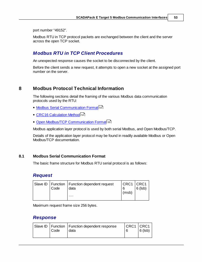
SCADAPack E Target 5 Modbus Communication Interfaces 53
port number “49152”.
Modbus RTU in TCP protocol packets are exchanged between the client and the serveracross the open TCP socket.
Modbus RTU in TCP Client Procedures
An unexpected response causes the socket to be disconnected by the client.
Before the client sends a new request, it attempts to open a new socket at the assigned portnumber on the server.
8 Modbus Protocol Technical Information
The following sections detail the framing of the various Modbus data communicationprotocols used by the RTU:
Modbus Serial Communication Format
CRC16 Calculation Method
Open Modbus/TCP Communication Format
Modbus application layer protocol is used by both serial Modbus, and Open Modbus/TCP.
Details of the application layer protocol may be found in readily available Modbus or OpenModbus/TCP documentation.
8.1 Modbus Serial Communication Format
The basic frame structure for Modbus RTU serial protocol is as follows:
Request
Slave ID FunctionCode
Function dependent requestdata
….
CRC16(msb)
CRC16 (lsb)
Maximum request frame size 256 bytes.
Response
Slave ID FunctionCode
Function dependent responsedata
CRC16
CRC16 (lsb)
53
54
55
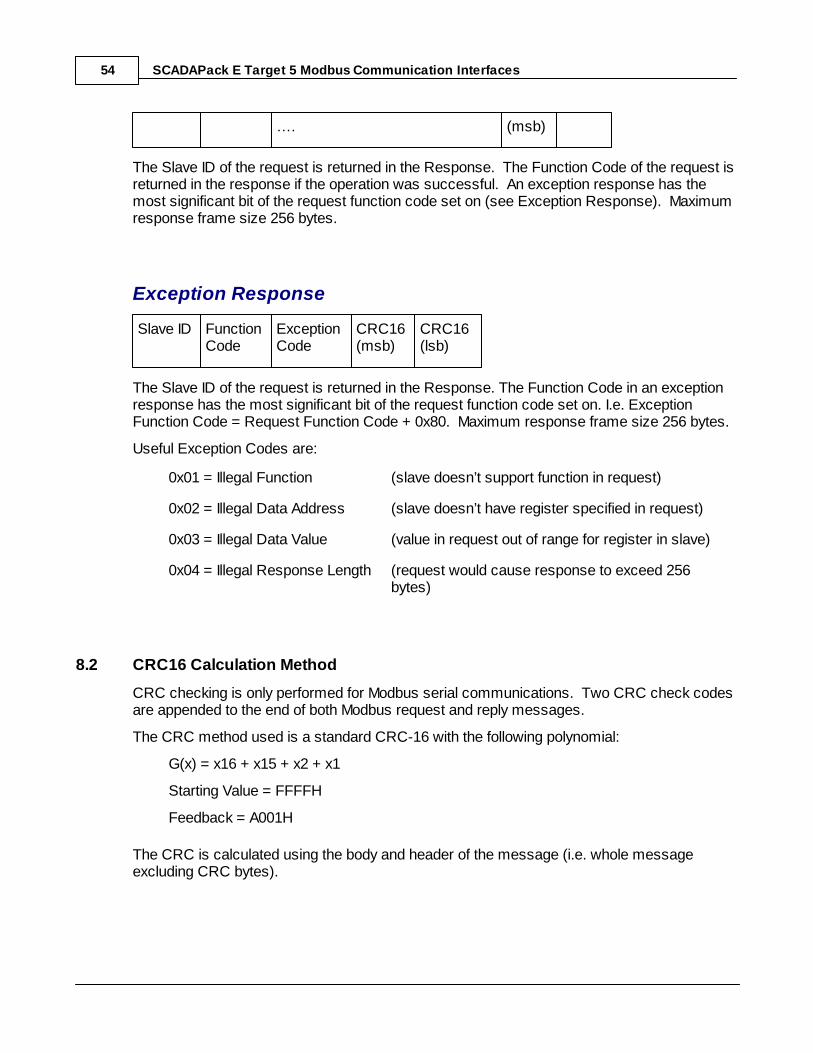
SCADAPack E Target 5 Modbus Communication Interfaces54
…. (msb)
The Slave ID of the request is returned in the Response. The Function Code of the request isreturned in the response if the operation was successful. An exception response has themost significant bit of the request function code set on (see Exception Response). Maximumresponse frame size 256 bytes.
Exception Response
Slave ID FunctionCode
ExceptionCode
CRC16(msb)
CRC16(lsb)
The Slave ID of the request is returned in the Response. The Function Code in an exceptionresponse has the most significant bit of the request function code set on. I.e. ExceptionFunction Code = Request Function Code + 0x80. Maximum response frame size 256 bytes.
Useful Exception Codes are:
0x01 = Illegal Function (slave doesn’t support function in request)
0x02 = Illegal Data Address (slave doesn’t have register specified in request)
0x03 = Illegal Data Value (value in request out of range for register in slave)
0x04 = Illegal Response Length (request would cause response to exceed 256bytes)
8.2 CRC16 Calculation Method
CRC checking is only performed for Modbus serial communications. Two CRC check codesare appended to the end of both Modbus request and reply messages.
The CRC method used is a standard CRC-16 with the following polynomial:
G(x) = x16 + x15 + x2 + x1
Starting Value = FFFFH
Feedback = A001H
The CRC is calculated using the body and header of the message (i.e. whole messageexcluding CRC bytes).
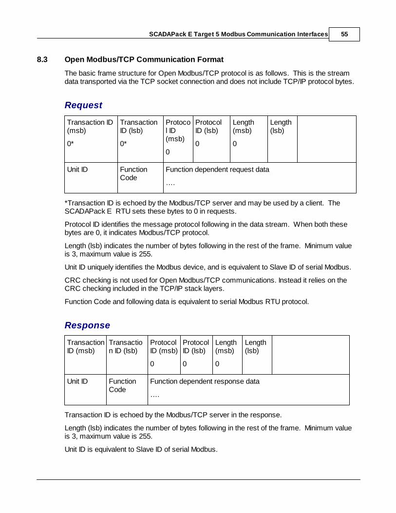
SCADAPack E Target 5 Modbus Communication Interfaces 55
8.3 Open Modbus/TCP Communication Format
The basic frame structure for Open Modbus/TCP protocol is as follows. This is the streamdata transported via the TCP socket connection and does not include TCP/IP protocol bytes.
Request
Transaction ID(msb)
0*
TransactionID (lsb)
0*
Protocol ID(msb)
0
ProtocolID (lsb)
0
Length(msb)
0
Length(lsb)
Unit ID FunctionCode
Function dependent request data
….
*Transaction ID is echoed by the Modbus/TCP server and may be used by a client. TheSCADAPack E RTU sets these bytes to 0 in requests.
Protocol ID identifies the message protocol following in the data stream. When both thesebytes are 0, it indicates Modbus/TCP protocol.
Length (lsb) indicates the number of bytes following in the rest of the frame. Minimum valueis 3, maximum value is 255.
Unit ID uniquely identifies the Modbus device, and is equivalent to Slave ID of serial Modbus.
CRC checking is not used for Open Modbus/TCP communications. Instead it relies on theCRC checking included in the TCP/IP stack layers.
Function Code and following data is equivalent to serial Modbus RTU protocol.
Response
TransactionID (msb)
Transaction ID (lsb)
ProtocolID (msb)
0
ProtocolID (lsb)
0
Length(msb)
0
Length(lsb)
Unit ID FunctionCode
Function dependent response data
….
Transaction ID is echoed by the Modbus/TCP server in the response.
Length (lsb) indicates the number of bytes following in the rest of the frame. Minimum valueis 3, maximum value is 255.
Unit ID is equivalent to Slave ID of serial Modbus.
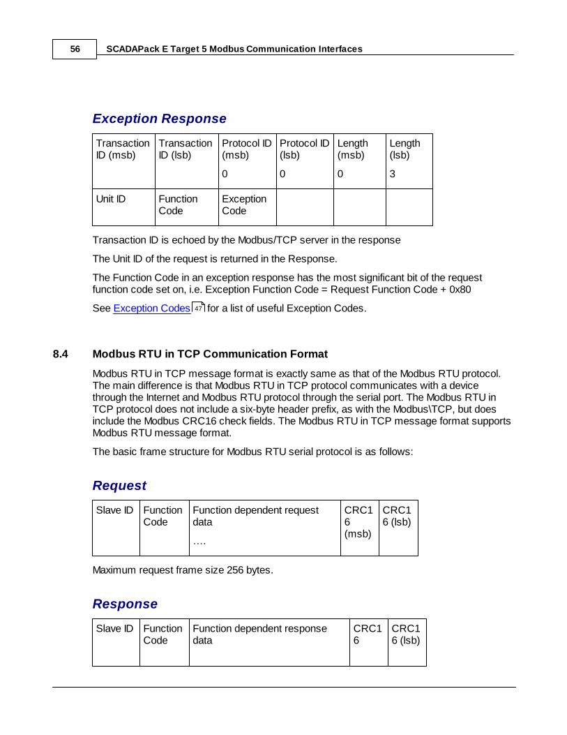
SCADAPack E Target 5 Modbus Communication Interfaces56
Exception Response
TransactionID (msb)
TransactionID (lsb)
Protocol ID(msb)
0
Protocol ID(lsb)
0
Length(msb)
0
Length(lsb)
3
Unit ID FunctionCode
ExceptionCode
Transaction ID is echoed by the Modbus/TCP server in the response
The Unit ID of the request is returned in the Response.
The Function Code in an exception response has the most significant bit of the requestfunction code set on, i.e. Exception Function Code = Request Function Code + 0x80
See Exception Codes for a list of useful Exception Codes.
8.4 Modbus RTU in TCP Communication Format
Modbus RTU in TCP message format is exactly same as that of the Modbus RTU protocol.The main difference is that Modbus RTU in TCP protocol communicates with a devicethrough the Internet and Modbus RTU protocol through the serial port. The Modbus RTU inTCP protocol does not include a six-byte header prefix, as with the Modbus\TCP, but doesinclude the Modbus CRC16 check fields. The Modbus RTU in TCP message format supportsModbus RTU message format.
The basic frame structure for Modbus RTU serial protocol is as follows:
Request
Slave ID FunctionCode
Function dependent requestdata
….
CRC16(msb)
CRC16 (lsb)
Maximum request frame size 256 bytes.
Response
Slave ID FunctionCode
Function dependent responsedata
CRC16
CRC16 (lsb)
47
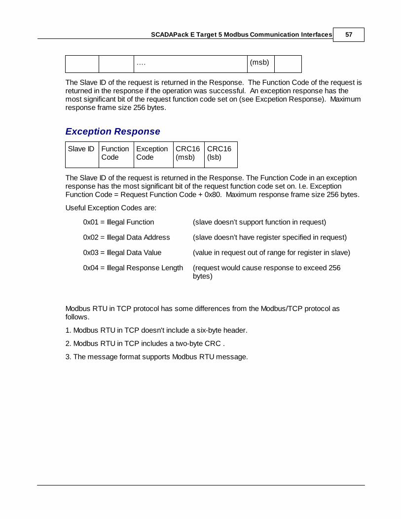
SCADAPack E Target 5 Modbus Communication Interfaces 57
…. (msb)
The Slave ID of the request is returned in the Response. The Function Code of the request isreturned in the response if the operation was successful. An exception response has themost significant bit of the request function code set on (see Excpetion Response). Maximumresponse frame size 256 bytes.
Exception Response
Slave ID FunctionCode
ExceptionCode
CRC16(msb)
CRC16(lsb)
The Slave ID of the request is returned in the Response. The Function Code in an exceptionresponse has the most significant bit of the request function code set on. I.e. ExceptionFunction Code = Request Function Code + 0x80. Maximum response frame size 256 bytes.
Useful Exception Codes are:
0x01 = Illegal Function (slave doesn’t support function in request)
0x02 = Illegal Data Address (slave doesn’t have register specified in request)
0x03 = Illegal Data Value (value in request out of range for register in slave)
0x04 = Illegal Response Length (request would cause response to exceed 256bytes)
Modbus RTU in TCP protocol has some differences from the Modbus/TCP protocol asfollows.
1. Modbus RTU in TCP doesn't include a six-byte header.
2. Modbus RTU in TCP includes a two-byte CRC .
3. The message format supports Modbus RTU message.


![[PSS 1-2B6 A] Model NOCT60A Net Oil Coriolis Transmittercth.ca/wp-content/uploads/2017/11/pss_1-2b6a.pdf · Modbus communication. ... these logic programs is the SCADAPack Workbench](https://img.pdfslide.net/doc/110x75/5ae3a5e37f8b9a595d8eb510/pss-1-2b6-a-model-noct60a-net-oil-coriolis-communication-these-logic-programs.jpg)