Embed Size (px)
Citation preview

S E M I N A R I N S O F T W A R E E N G I N E E R I N G
P R E S E N T E R
A V N E R B A R R
SCADE1

Introduction
What is SCADE? Software Critical Application Development Environment, a Lustre-
based IDE for designing safety critical embedded software applications for reactive systems. Generates C-code
A product developed by Esterel Technologies. Scade includes a graphical interface to build formal models in the synchronous data-flow language Lustre Algorithm Design Architecture Design Software Design and Verification Code Generation Code Deployment
Lustre is a formally defined, declarative, and synchronous dataflow programming language, for programming reactive systems. It began as a research project in the early 1980s
2

Who uses SCADE
Civilian and military avionics
Airbus, Boeing, GE, Pratt & Whitney… Many more
Autopilots, Engine Control, Fuel Management, Cockpit Display…
Defense & space industries
Elbit, Lockheed, NASA….
Flight warning systems…
Energy and transportation
GM, Ford, Nuclear Reactors …
Controllers, Braking systems, Fuel Management, Rail control…
3

SCADE
Scade (SCADE…) suite includes the following: A graphical editor to build formal models and specify properties The Scade Design Verifier, built on top of Prover SL DE (to be discussed in
depth), to automatically verify that models satisfy all safety properties
A C code generator - Since the code is automatically generated from the formal model, it is correct by construction, assuming the formal model is correct
Scade Design Verifier (Prover SL DE) Automatically extends Lustre models by injecting faults, using libraries of typical failures Allows to perform Failure Mode and Effect Analysis, which consists of verifying
whether systems remain safe when selected components fail
The tool can compute minimal combinations of failures breaking systems' safety, which is similar to Fault Tree Analysis
4

Work Flow – Development Cycle
Tools to combine the activities of system engineering
5

Work Flow – Development Cycle
Main Tools
6

IDE
Work Space
Output
Shortcuts
Main View
7

Work Methodology
Designing systems with Scade involves these steps Model Capture
Initial stage of the workflow understand specifications of the model and capture them using modeling tools – Use Scade application to design models with graphical formalism Modeling functional design with Data Flow Modeling functional design with Control Flow
• Safe State Machines (SSM)
Define the data structure of model using data types and constants that can be instantiated through SCADE graphical formalism
Model Debugging The second stage of the workflow is a three-stage process
Running coherence checks• SCADE models are automatically and thoroughly checked before simulation code or target code
is generated but it is possible to check model semantics at any time
Simulation sessions• SCADE can run interactive simulation sessions to dynamically check the model, to read
through the simulated code with the help of code highlights and to play simulation scenarios
Formal verification analysis
Code Generation The last stage of the workflow consists of generating target code. The SCADE model
designed can be used to generate code automatically from a single source. Generated code is correct and optimized by SCADE KCG CODE GENERATOR
8
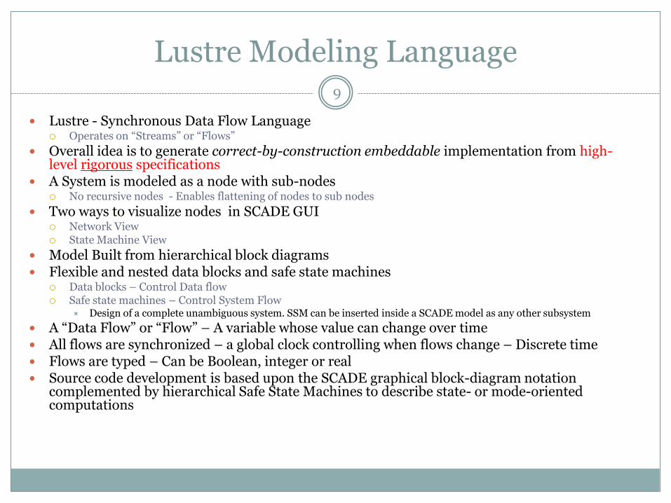
Lustre Modeling Language
Lustre - Synchronous Data Flow Language Operates on “Streams” or “Flows”
Overall idea is to generate correct-by-construction embeddable implementation from high-level rigorous specifications
A System is modeled as a node with sub-nodes No recursive nodes - Enables flattening of nodes to sub nodes
Two ways to visualize nodes in SCADE GUI Network View State Machine View
Model Built from hierarchical block diagrams Flexible and nested data blocks and safe state machines
Data blocks – Control Data flow Safe state machines – Control System Flow
Design of a complete unambiguous system. SSM can be inserted inside a SCADE model as any other subsystem
A “Data Flow” or “Flow” – A variable whose value can change over time All flows are synchronized – a global clock controlling when flows change – Discrete time Flows are typed – Can be Boolean, integer or real Source code development is based upon the SCADE graphical block-diagram notation
complemented by hierarchical Safe State Machines to describe state- or mode-oriented computations
9

Lustre Modeling Language Cont‟d
Nodes – Combine flows to generate new flows Nodes can be either graphical or textual A node has inputs, outputs and its functionality
Basic provided Nodes: Logic operators (AND, OR NOR… ) Operators ( +, - ….) Timed Operators
Basic provided Nodes Timed Operators:
Delays: PRE operator makes it possible to refer to the previous value of a flow. It can, for example, be used to memorize values A = PRE A
Initial value: The -> operator is used to specify the value of a flow during the first time stepA = True ->NOT PRE A Defines flow A to be initially True. Afterwards the value is inverted every time step - square clock signal.
10

Lustre Model Coherence
Semantic Checking – Check if the model conforms to SCADE language semantics
Model topology must be consistent
No orphan states or missing connections
Syntax Checking – Check if the model is syntactically correct with respect to the graphical and textual formalism used in SCADE
Cycle Detection – State Machines that may end up in loops
11

Lustre Model Simulation
Run simulation sessions in SCADE
Dynamically check the model
Run simulation scenarios
Run through the simulated code (Debug)
Observe reactions graphically
Signals, outputs, inputs etc
12

SCADE Formalism13
Programs are implementations of control algorithms, with many parts acting concurrently but in a deterministic way
Two specification formalisms
Block diagrams for continuous control
State machines for discrete control

Block Diagrams for Continuous Control14
Continuous control – Sampling sensors at regular time intervals and performing computations on their values
Continuous control is depicted by block diagrams Boxes compute mathematical functions, filters and delays
Arrows denote flows of data between boxes
Data flows continuously between blocks that continuously compute their outputs from their inputs
All blocks compute concurrently and the blocks only communicate through the flows
Some flows may carry Boolean or discrete values tested in computational blocks or acting on flow switches or multiplexors

Block Diagrams for Continuous Control Cont‟d
15
SCADE blocks are fully hierarchical
Hierarchy makes it possible to break design complexity by a divide-and-conquer approach and to design reusable library blocks

Safe State Machines for Discrete Control
16
Discrete control - changing behavior according to external events originating either from discrete sensors and user inputs or from internal program events (threshold detection etc.)
Adding mode-control Boolean flows to block diagrams becomes messy when discrete control is non-trivial -> resort to state machines

Safe State Machines for Discrete Control
17

Mixed Continuous / Discrete Control18
SCADE allows to couple data flow and state machine styles
SSM included in block diagrams design to compute and propagate functioning modes. Discrete signals to which SSM reacts and sends back are transformed into Boolean data flows in the block diagram

Computation Model19
“Cycle Based” computation model Once the input sensors are read, the programs starts
computing the cycle outputs In a SCADE block diagram specification, each block has a
cycle and all blocks act concurrently Blocks can all have the same cycle or they can have different
cycles At each of its cycle, a block reads its inputs and generates its
outputs. If two connected blocks A and B have the same cycle, the outputs of A are used by B in the same cycle, unless an explicit delay is added between A and B
SSM have the very same notion of a cycle Block diagrams and SSMs in the same design also
communicate synchronously at each cycle

Simple SCADE Lustre Program – Compute an Average
20
I,N,A – data flows
pre – delays a sequence by one cycle
pre(A) – (-,A0,A1,…At…) where the first element is unintialized
„->‟ initialization operator returns its left operand at first cycle and its right operand at further cycles
The N symbol denotes the sequence (1,2,3….)
“A“ denotes the required sequence of average values

Example
Elevator Controller Example: The Network View
21

Example Cont‟d
Textual representation
Node DefVar Name
22

Example Cont‟d - Requirements
Lustre for expressing safety requirements The system is in a safe state denoted by a specific flow in the model
being true
The model checker verifies whether this flow is ALWAYS true
Performs safety analysis by proving that the system constantly remains in a safe state
In example - Requirements would be: OpensWhenSafe = (OpenRequest and AtLevel and Stopped) ->
SafeOpen;
ClosesWhenSafe = (!AtLevel or !Stopped) -> !SafeOpen;
“If you are not at level or haven’t stopped it isn’t safe to open!”
23

Lustre Modeling Language Cont‟d
Assertions – Similar to requirements. Restrict possible values of input flows. Indicates to compiler to optimize the code (program possesses some known properties)
Generalize equations and consist of Boolean expressions that should always be true
assert not (OpenRequest and CloseRequest);
In C code generated from a Lustre model, assertions can be translated into C macro calls
Speeds up verification – only use inputs whom satisfy assertions
24

Safety Properties25
Motivation : We want to design a correct system that is also safe
The safety of a critical application does not depend on the total correctness of its control program but rather on an often small set of properties that the program should fulfill For instance - A critical situation should raise an alarm
“Safety” properties indicate a given situation which should “never” appear or that a given statement should always hold
Safety property for a train – Relevant question is not that a train will eventually stop, but rather it never crosses a red light – Safety properties need to be defined correctly
Safety properties can be verified by checking properties of reachable states

Specification of safety properties26
Lustre can be considered as a subset of a temporal logic -> Express temporal property P by a Boolean expression B such that P holds if and only if expression B is always true during any execution path of the program Implemented using the assertion mechanism of LUSTRE as we saw
in previous slides
Example “any occurrence of a critical situation must be followed by an alarm within a five seconds delay” 3 events – critical situation occurrence, alarm, deadline “Any occurrence of event A is followed by an occurrence of event B
before the next occurrence of event C” Lustre can only “look” backwards -> need to change the wording “Any time C occurs, either A has never occurred previously, or B has
occurred since the last occurrence of A”

Specification of safety properties27
node onceBfromAtoC(A,B,C: bool) returns (X: bool);
let
X = implies(C,never(A) or since(B,A));
tel

Proof Engine - Prover SL DE
There are two ways to verify that systems are reliable
Failure Mode and Effect Analysis (FMEA):
Find the consequences of failures of components and its consequences – achieved through simulation
Fault Tree Analysis (FTA):
This method is the opposite - find the causes of a specific safety violation, find combinations of components which must fail in order to make the system unsafe
Prover SL DE supports the two methods
28

Prover SL DE - Verification
Implements an efficient algorithm SAT model checking extended to arithmetic Reduced Ordered Binary Decision Diagrams (ROBDDs) Linear Programming Constraint propagation
Change the problem to an easier one with out changing the solutions
Similar to model checking State graph of the program is built (finite number of states) each property is checked on the state
graph
Scade Design Verifier (Prover SL DE) verifies safety properties of Transition Systems
Transition system: A transition system is a tuple (S,So,T) where:
S = a set of states S0 is the set of initial states T = S x S is the transition relation
Safety Property (P): Set of good states ReachT(S): The set of states reachable from S using the transition relation T
29

Verifying Safety (Algorithm) Cont‟d
We want to decide if a transition system is safe:
Given a transition system M = (S,So,T) and safety property P, does hold?
Lustre models are transition systems. The state of a Lustre model is denoted by the current values of all its flows
Initial states are specified in the model using -> sign
The transition relation is specified using delay operators (PRE)
The set of states – the set of all assignments to flows in the model
PSachT )(Re 0
30

Verifying Safety (Algorithm) Cont‟d
Potentially infinite because of unbounded types (int+reals)
Lustre can express complex arithmetic expressions
Prover SL DE is limited to:
Linear arithmetic over the set Q
Non-Linear arithmetic over finite domains
Building explicit representation of reachable states isn‟t practical. Instead represent symbolically using predicates
Non-reachability of bad sets is equivalent to checking for non-satisfiability of Boolean and linear arithmetic formulas
31

SAT based model Checking
SAT-based model checking extended to arithmetic
For a set of states S, let S(s) be a predicate such that
For a sequence of states s0….sn let path(so…sn) be a predicate denoting that the sequence corresponds to a path through the graph of the transition relation
The reachability problem for a transition system (S,S0,T) can be denoted as follows:
Tw0 methods for solving this problem
Bounded Model Checking
Induction Over Time
)(sSSs
1)siT(si,:1}-,1,...n{0,i.sn)path(so...
)()()...(:...:0 0000 nnn sPsandSsspathssn
32

SAT based model Checking – Cont‟d
Bounded Model Checking – Suitable for debugging i.e. finding errors in unsafe systems
Proceed iteratively by increasing n until bmcn is falsifiable in which case we have found a shortest path to a bad state
Problem! Method will not terminate for safe systems
Induction over Time
Prove on induction over k that the system is safe
)()()...()...( 0000 nnnn sPsandSsspathssbmc
33

SAT based model Checking – Cont‟d
Induction over Time – Continued
Increase n starting from 0 until:
If we succeed in proving the aforementioned-> system is safe
Otherwise the bounded model checking step of the base case would have detected it
Problem: Incompleteness – Consider a case s.t. an unreachable loop leads to a bad state
Induction step will never succeed
34

Satisfiability of Formulas
Solution:
Modify the predicate to be loop free for all i!=j
We now have a model that decides if a system is safe or not. The kind of formulae we have to deal with are NP Hard. A math formula combines Boolean propositions and linear arithmetic predicates but there are powerful heuristics and provers which can solve quickly
35

Satisfiability of Formulas Cont‟d
The proof solver engine implements an efficient solver for MATH-SAT
36

Reliability Analysis
Now that we understand the underlying principles in building the model, we can delve into extending the model at hand to accommodate failure and safety analysis
Failure – inability of a piece of equipment to perform its task
We distinguish between system level failures and component level failures. If a system as a whole fails to meet its expected requirement we say it is unsafe
A system is reliable when it can sustain several failures before becoming unsafe N-Fault-Tolerant – The ability to remain safe under N failures
There are two popular ways to assess reliability of a system
37

Reliability Analysis - FTA and FMEA
FMEA – Failure Mode and Effect Analysis Failure Mode – refers to the way a component fails
A valve may be stuck open, closed, in between. Each is distinguished as a “mode”
Investigate the effects of failure modes Designers specify a list of components that fail in addition to the way they fail
Simulate system and check if it becomes unsafe
FTA – Fault Tree Analysis Considered as an “opposite” approach
Find the causes of safety violations
A fault tree is a graph relating failures of components and safety violations
Tree root is called Top Level Event – represents an event that should not occur in a safe system
In lift example – top event consists of the opening of the doors while it is moving or when it is not at the level of the floor
38

Reliability Analysis - FTA and FMEA Cont‟d
FTA Continued –
Leaves of the tree are called basic events
Represent failures of components as well as their failure mode
Motion detector in elevator, detecting lift is at level etc.
Internal nodes are Boolean connectives. The connective represented in the example is an OR gate
Fault tree is a graphical representation of a Boolean formula satisfied when the system is unsafe
Goal of FTA – find minimal combinations of events leading to the top event
39

Reliability Analysis - Fault Injection in SCADE
In order to assess the reliability of a system the model must include failure modes Adding failure modes into an existing model is called fault injection
In SCADE there is a large fault library with common scenarios
SCADE has a GUI which allows designers to select the components susceptible to fail as well as their failure mode. Failures of the components are modeled by modifying flows representing components outputs Original flows are called nominal flows New flows are called extended flows
The value of an extended flow is decided by the failure mode – all possible failure modes are modeled by a Lustre node called failure mode node One of the inputs is the nominal flow and the output is the extended flow Remaining inputs are Boolean flows called failure mode variable which
control the mode that is triggered
40

FMEA in SCADE
With the GUI designers constrain the occurrence of failures
Example:
At most N failure modes can occur
At most N failure modes can happen simultaneously
Once a component fails it never recovers
Specified in Lustre similarly to requirements
41

FTA in SCADE
Goal – compute minimal combinations of failures causing a safety violation
Tool checks whether the system is safe assuming that N failure modes occur, starting with N= 0 and increasing N accordingly
At each step, Scade Design Verifier verifies if the system is safe. If not will generate a counter example with the values of each flow at each time step until the violation
N = 0 – equivalent to the system is safe
42

Code Generator KCG
ANSI Code Readable and traceable
Optimized by generator - Execution speed/memory optimization
Memory is statically allocated
The Stack is bounded
Guaranteed no dead code
Deterministic behavior
Compiler Verification Verifies the machine code generated is correct
Source code has no recursion, unbounded loops, code with side effects, function pointers, pointer arithmetic
From the GUI easy access to relevant code
43

Conclusion
SCADE presents a tool and methodology SCADE is used widely in designing safety critical systems in the
aircraft, watercraft and automobile industry and is considered very practical for these applications used by over 50 large companies
Companies report on savings of over 35% on development costs Software update time is significantly shortened, reducing costs and
raising reliability Lowers testing costs Elimination of coding errors Qualified by European and American Quality agencies Security? Price – 20,000$ per station
44

Questions?45


![SCADE AADL - ERTS 2018SCADE [4], acronym for Safety Critical Application Development Environment, is a suite of strongly integrated tools covering the following aspects: • SCADE](https://img.pdfslide.net/doc/110x75/5f43e44c7cf2b9701a011e05/scade-aadl-erts-2018-scade-4-acronym-for-safety-critical-application-development.jpg)