Embed Size (px)
Citation preview
SAUDI ARAMCO JOURNAL OF TECHNOLOGY FALL 2016
ABSTRACT
Scale formation has been a persistent challenge in many producing sour gas wells from the Khuff reservoir in Saudi Arabia. Accumulation of scale deposits on downhole tubulars and in wellhead manifolds interferes with field operation, lim-its well accessibility and decreases well productivity. Extensive efforts have been devoted to understanding the scale depo-sition process and to developing a cost-effective mitigation strategy. This article discusses the up-to-date knowledge re-garding scale formation in these prolific gas wells and presents the descaling technologies deployed in them.
Scale composition analyses have been performed for a large number of the deposits collected over the years during well workovers and interventions. Mineral phases across a wide range were identified, and their distribution showed signifi-cant variations within the collected samples. Scale found in the subject wells often consisted of several different mineral phases. Iron sulfides (FeS) were usually the dominant compo-nents; these included pyrrhotite, troilite, mackinawite, pyrite, marcasite and greigite. Ferric iron scales, such as hematite, magnetite, akaganeite, goethite and lepidocrocite, were also common in the scale mixtures that were examined. Common mineral scales, especially calcite, were often found, and iron carbonate and other ferrous iron compounds were also iden-tified. The relative abundance of these minerals showed wide-ranging variations from well to well. Those variations also changed with depth and time in a single well. A more in-teresting phenomenon was the layered structure of the scale deposits, with two distinct layers having very different compo-sitions. These results provided information critical for a better understanding of the scaling process.
Scale removal with chemical methods has had limited suc-cess in the past. Scale dissolvers based on hydrochloric (HCl) acid, in particular, caused severe tubular corrosion and forma-tion damage. As an alternative approach, different mechanical techniques have been tested and implemented over the years. These field experiences are reviewed in the article. Also, the requirements for scale dissolvers and the challenges they pres-ent are discussed.
INTRODUCTION
The prolific Khuff formation in Saudi Arabia is a high-pres-sure/high temperature reservoir underlying the massive Ghawar field. The majority of the reservoir is classified as sour, which means it generally contains high amounts of hydrogen sul-fide (H2S) and carbon dioxide (CO2). Figure 1 shows the typi-cal H2S and CO2 contents in reservoir fluids at different areas of the Khuff reservoir. Field development started here in the early 1980s in the south and south-central areas. Low carbon
Scale Deposition and Removal in Khuff Sour Gas Wells
Authors: Dr. Qiwei Wang, Dr. Syed R. Zaidi, Jairo A. Leal Jauregui, Irfan Syafii, Amro E. Mukhles, Dr. Tao Chen, Dr. Fakuen F. Chang and Mauricio A. Espinosa
Fig. 1. Typical H2S and CO2 concentrations at different areas of the Khuff reservoir.
H2S: < 1.5% CO2: 4%
H2S: 6% CO2: 3%
H2S: 2% CO2: 2.5%
H2S: 15% CO2: 3.5%
H2S: > 20% CO2: 5%
Fig. 1. Typical H2S and CO2 concentrations at different areas of the Khuff reservoir.
FALL 2016 SAUDI ARAMCO JOURNAL OF TECHNOLOGY
mild steel was used for the early well completions. Downhole corrosion inhibition was initially considered, but the idea was dropped after pilot testing programs in the mid-1980s. Although tubing-casing-annulus communication occurred in several wells within 2 to 6 years of service1, the mild steel tubu-lars still achieved long service lives in most wells2.
While corrosion is not a major concern, scale formation has been a persistent problem impacting field operations since the early production days3. Scales deposited on tubulars limited wellbore surveillance, damaged and interfered with logging tools, and restricted downhole intervention. Downhole scales were also transported to the surface and accumulated at flow lines near the wellhead. This article provides a detailed dis-cussion of scale compositions and the scale formation process. This study revealed that scale deposits in the Khuff wells have more complicated compositions than previously reported, to the author’s knowledge. This article also highlights the chal-lenges that come with using FeS scale dissolvers and experi-ences with mechanical descaling operations.
GENERAL DESCRIPTION
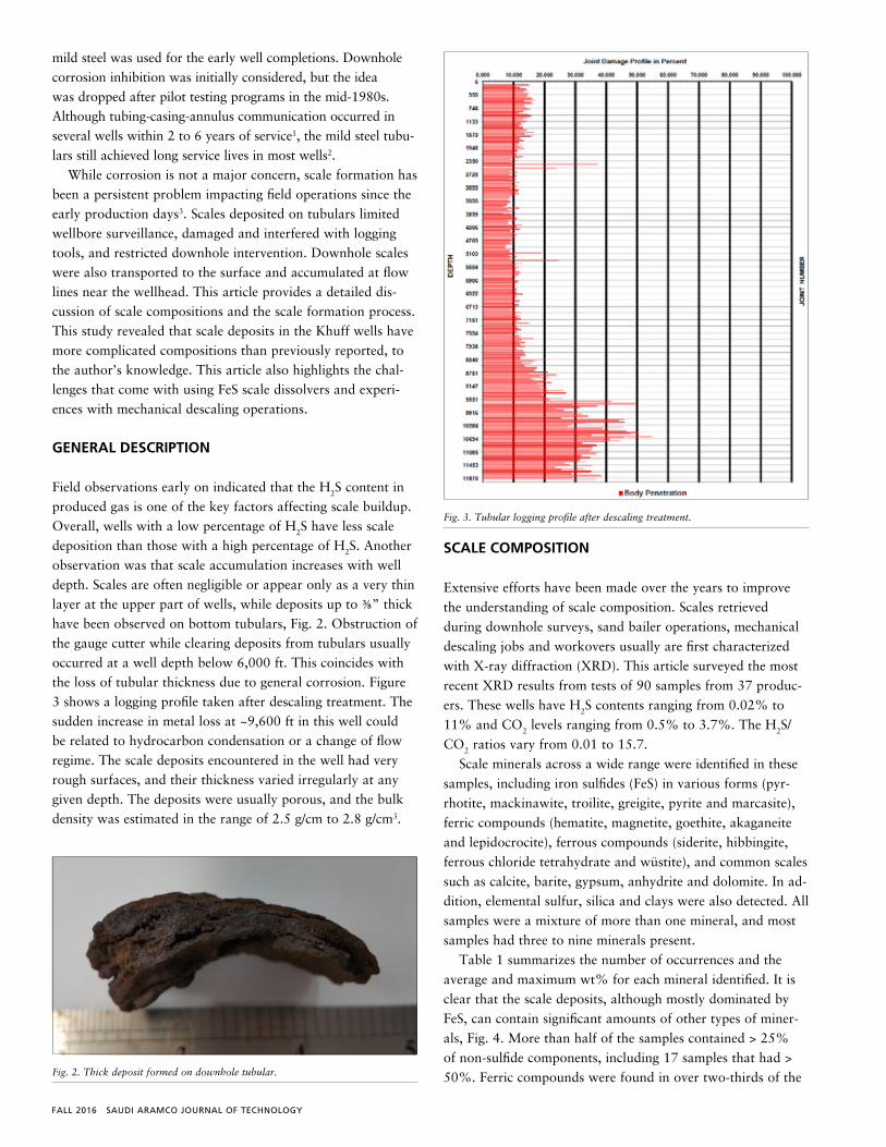
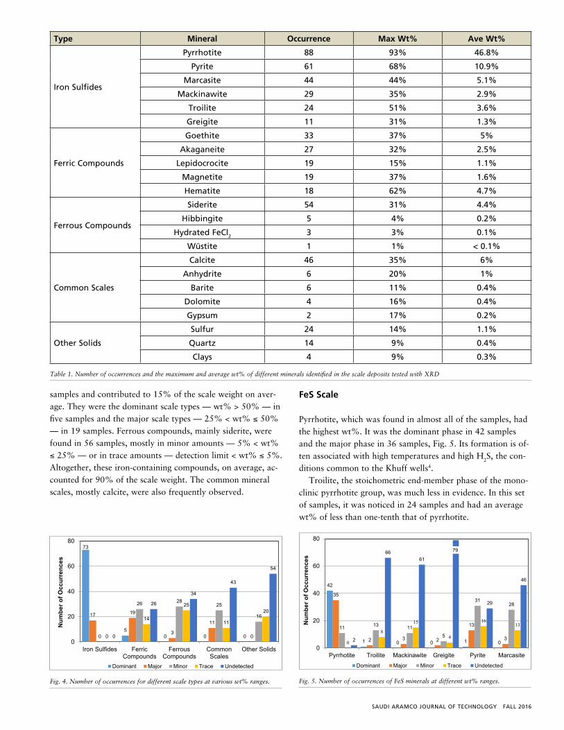
Field observations early on indicated that the H2S content in produced gas is one of the key factors affecting scale buildup. Overall, wells with a low percentage of H2S have less scale deposition than those with a high percentage of H2S. Another observation was that scale accumulation increases with well depth. Scales are often negligible or appear only as a very thin layer at the upper part of wells, while deposits up to ⅜” thick have been observed on bottom tubulars, Fig. 2. Obstruction of the gauge cutter while clearing deposits from tubulars usually occurred at a well depth below 6,000 ft. This coincides with the loss of tubular thickness due to general corrosion. Figure 3 shows a logging profile taken after descaling treatment. The sudden increase in metal loss at ~9,600 ft in this well could be related to hydrocarbon condensation or a change of flow regime. The scale deposits encountered in the well had very rough surfaces, and their thickness varied irregularly at any given depth. The deposits were usually porous, and the bulk density was estimated in the range of 2.5 g/cm to 2.8 g/cm3.
SCALE COMPOSITION
Extensive efforts have been made over the years to improve the understanding of scale composition. Scales retrieved during downhole surveys, sand bailer operations, mechanical descaling jobs and workovers usually are first characterized with X-ray diffraction (XRD). This article surveyed the most recent XRD results from tests of 90 samples from 37 produc-ers. These wells have H2S contents ranging from 0.02% to 11% and CO2 levels ranging from 0.5% to 3.7%. The H2S/CO2 ratios vary from 0.01 to 15.7.
Scale minerals across a wide range were identified in these samples, including iron sulfides (FeS) in various forms (pyr-rhotite, mackinawite, troilite, greigite, pyrite and marcasite), ferric compounds (hematite, magnetite, goethite, akaganeite and lepidocrocite), ferrous compounds (siderite, hibbingite, ferrous chloride tetrahydrate and wüstite), and common scales such as calcite, barite, gypsum, anhydrite and dolomite. In ad-dition, elemental sulfur, silica and clays were also detected. All samples were a mixture of more than one mineral, and most samples had three to nine minerals present.
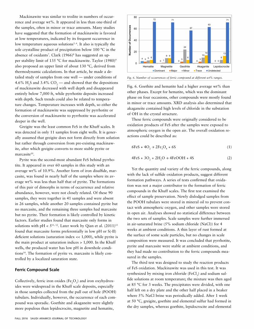
Table 1 summarizes the number of occurrences and the average and maximum wt% for each mineral identified. It is clear that the scale deposits, although mostly dominated by FeS, can contain significant amounts of other types of miner-als, Fig. 4. More than half of the samples contained > 25% of non-sulfide components, including 17 samples that had > 50%. Ferric compounds were found in over two-thirds of the
Fig. 1. Typical H2S and CO2 concentrations at different areas of the Khuff reservoir.
H2S: < 1.5% CO2: 4%
H2S: 6% CO2: 3%
H2S: 2% CO2: 2.5%
H2S: 15% CO2: 3.5%
H2S: > 20% CO2: 5%
Fig. 2. Thick deposit formed on downhole tubular.
Fig. 3. Tubular logging profile after descaling treatment.
Fig. 2. Thick deposit formed on downhole tubular.
Fig. 3. Tubular logging profile after descaling treatment.
Fig. 4. Number of occurrences for different scale types at various wt% ranges.
73
50 0 0
17 19
3
11
00
26 2825
16
0
14
25
11
20
0
26
34
43
54
0
20
40
60
80
Iron Sulfides FerricCompounds
FerrousCompounds
CommonScales
Other Solids
Num
ber o
f Occ
urre
nces
Dominant Major Minor Trace Undetected
SAUDI ARAMCO JOURNAL OF TECHNOLOGY FALL 2016
samples and contributed to 15% of the scale weight on aver-age. They were the dominant scale types — wt% > 50% — in five samples and the major scale types — 25% < wt% ≤ 50% — in 19 samples. Ferrous compounds, mainly siderite, were found in 56 samples, mostly in minor amounts — 5% < wt% ≤ 25% — or in trace amounts — detection limit < wt% ≤ 5%. Altogether, these iron-containing compounds, on average, ac-counted for 90% of the scale weight. The common mineral scales, mostly calcite, were also frequently observed.
FeS Scale
Pyrrhotite, which was found in almost all of the samples, had the highest wt%. It was the dominant phase in 42 samples and the major phase in 36 samples, Fig. 5. Its formation is of-ten associated with high temperatures and high H2S, the con-ditions common to the Khuff wells4.
Troilite, the stoichometric end-member phase of the mono-clinic pyrrhotite group, was much less in evidence. In this set of samples, it was noticed in 24 samples and had an average wt% of less than one-tenth that of pyrrhotite.
Fig. 2. Thick deposit formed on downhole tubular.
Fig. 3. Tubular logging profile after descaling treatment.
Fig. 4. Number of occurrences for different scale types at various wt% ranges.
73
50 0 0
17 19
3
11
00
26 2825
16
0
14
25
11
20
0
26
34
43
54
0
20
40
60
80
Iron Sulfides FerricCompounds
FerrousCompounds
CommonScales
Other Solids
Num
ber o
f Occ
urre
nces
Dominant Major Minor Trace Undetected
Fig. 4. Number of occurrences for different scale types at various wt% ranges.
Type Mineral Occurrence Max Wt% Ave Wt%
Iron Sulfides
Pyrrhotite 88 93% 46.8%
Pyrite 61 68% 10.9%
Marcasite 44 44% 5.1%
Mackinawite 29 35% 2.9%
Troilite 24 51% 3.6%
Greigite 11 31% 1.3%
Ferric Compounds
Goethite 33 37% 5%
Akaganeite 27 32% 2.5%
Lepidocrocite 19 15% 1.1%
Magnetite 19 37% 1.6%
Hematite 18 62% 4.7%
Ferrous Compounds
Siderite 54 31% 4.4%
Hibbingite 5 4% 0.2%
Hydrated FeCl2 3 3% 0.1%
Wüstite 1 1% < 0.1%
Common Scales
Calcite 46 35% 6%
Anhydrite 6 20% 1%
Barite 6 11% 0.4%
Dolomite 4 16% 0.4%
Gypsum 2 17% 0.2%
Other Solids
Sulfur 24 14% 1.1%
Quartz 14 9% 0.4%
Clays 4 9% 0.3%
Table 1. Number of occurrences and the maximum and average wt% of different minerals identified in the scale deposits tested with XRD
Fig. 5. Number of occurrences of FeS minerals at different wt% ranges.
Fig. 6. Number of occurrences of ferric compound at different wt% ranges.
42
1 0 0 1 0
35
2 3 2
13
3
11 13 11
5
3128
0
8
15
4
1613
2
6661
79
29
46
0
20
40
60
80
Pyrrhotite Troilite Mackinawite Greigite Pyrite Marcasite
Num
ber o
f Occ
urre
nces
Dominant Major Minor Trace Undetected
40 0 0 0
3 1 3 30
59
24
1066
96
14 13
72 71
5763
71
0
20
40
60
80
Hematite Magnetite Geothite Akaganite Lepidocrocite
Num
ber o
f Occ
urre
nces
Dominant Major Minor Trace Undetected
Fig. 5. Number of occurrences of FeS minerals at different wt% ranges.
FALL 2016 SAUDI ARAMCO JOURNAL OF TECHNOLOGY
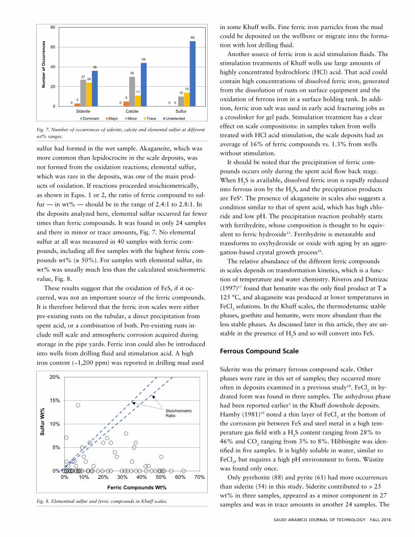
Mackinawite was similar to troilite in numbers of occur-rence and average wt%. It appeared in less than one-third of the samples, often in minor or trace amounts. Many studies have suggested that the formation of mackinawite is favored at low temperatures, indicated by its frequent occurrence in low temperature aqueous solutions5, 6. It also is typically the sole crystalline product of precipitation below 100 °C in the absence of oxidants7. Clark (1966)8 has suggested an up-per stability limit of 135 °C for mackinawite. Taylor (1980)9 also proposed an upper limit of about 130 °C, derived from thermodynamic calculations. In that article, he made a de-tailed study of samples from one well — under conditions of 4.6% H2S and 3.4% CO2 — and showed that the depositions of mackinawite decreased with well depth and disappeared entirely below 7,000 ft, while pyrrhotite deposits increased with depth. Such trends could also be related to tempera-ture changes. Temperature increases with depth, so either the formation of mackinawite was suppressed by pyrrhotite or the conversion of mackinawite to pyrrhotite was accelerated deeper in the well.
Greigite was the least common FeS in the Khuff scales. It was detected in only 11 samples from eight wells. It is gener-ally assumed that greigite does not form directly from solution but rather through conversion from pre-existing mackinaw-ite, after which greigite converts to more stable pyrite or marcasite10.
Pyrite was the second-most abundant FeS behind pyrrho-tite. It appeared in over 60 samples in this study with an average wt% of 10.9%. Another form of iron disulfide, mar-casite, was found in nearly half of the samples where its av-erage wt% was less than half that of pyrite. The formations of this pair of dimorphs in terms of occurrence and relative abundance, however, were not closely related. Of these 90 samples, they were together in 41 samples and were absent in 26 samples, while another 20 samples contained pyrite but no marcasite, and the remaining three samples had marcasite but no pyrite. Their formation is likely controlled by kinetic factors. Earlier studies found that marcasite only forms in solutions with pH < 511, 12. Later work by Qian et al. (2011)13 found that marcasite forms preferentially in low pH or S(-II) deficient solutions (saturation index << 1,000), while pyrite is the main product at saturation indices > 1,000. In the Khuff wells, the produced water has low pH in downhole condi-tions14. The formation of pyrite vs. marcasite is likely con-trolled by a localized saturation state.
Ferric Compound Scale
Collectively, ferric iron oxides (Fe2O3) and iron oxyhydrox-ides were widespread in the Khuff scale deposits, especially in those samples collected from the pull out of hole (POOH) tubulars. Individually, however, the occurrence of each com-pound was sporadic. Goethite and akaganeite were slightly more populous than lepidocrocite, magnetite and hematite,
Fig. 6. Goethite and hematite had a higher average wt% than other phases. Except for hematite, which was the dominant phase on four occasions, other compounds were mostly found in minor or trace amounts. XRD analysis also determined that akaganeite contained high levels of chloride in the substation of OH in the crystal structure.
These ferric compounds were originally considered to be oxidation products of FeS after the samples were exposed to atmospheric oxygen in the open air. The overall oxidation re-actions could be described as:
6FeS + 4O2 → 2Fe3O4 + 6S (1)
4FeS + 3O2 + 2H2O → 4FeOOH + 4S (2)
Yet the quantity and variety of the ferric compounds, along with the lack of sulfide oxidation products, suggest different formation pathways. A series of tests confirmed that oxida-tion was not a major contributor to the formation of ferric compounds in the Khuff scales. The first test examined the effect of sample preservation. Newly dislodged samples from the POOH tubulars were stored in mineral oil to prevent con-tact with atmospheric oxygen, and other samples were stored in open air. Analyses showed no statistical difference between the two sets of samples. Scale samples were further immersed in air-saturated brine (5% sodium chloride (NaCl)) for 4 weeks at ambient conditions. A thin layer of rust formed at the surface of some scale particles, but no changes in scale composition were measured. It was concluded that pyrrhotite, pyrite and marcasite were stable at ambient conditions, and they had made no contribution to the ferric compounds mea-sured in the samples.
The third test was designed to study the reaction products of FeS oxidation. Mackinawite was used in this test. It was synthesized by mixing iron chloride (FeCl3) and sodium sul-fide solutions at room temperature; the mixture was then aged at 85 °C for 3 weeks. The precipitates were divided, with one half left on a dry plate and the other half placed in a beaker where 5% NaCl brine was periodically added. After 1 week at 50 °C, greigite, goethite and elemental sulfur had formed in the dry samples, whereas goethite, lepidocrocite and elemental
Fig. 5. Number of occurrences of FeS minerals at different wt% ranges.
Fig. 6. Number of occurrences of ferric compound at different wt% ranges.
42
1 0 0 1 0
35
2 3 2
13
3
11 13 11
5
3128
0
8
15
4
1613
2
6661
79
29
46
0
20
40
60
80
Pyrrhotite Troilite Mackinawite Greigite Pyrite Marcasite
Num
ber o
f Occ
urre
nces
Dominant Major Minor Trace Undetected
40 0 0 0
3 1 3 30
59
24
1066
96
14 13
72 71
5763
71
0
20
40
60
80
Hematite Magnetite Geothite Akaganite Lepidocrocite
Num
ber o
f Occ
urre
nces
Dominant Major Minor Trace Undetected
Fig. 6. Number of occurrences of ferric compound at different wt% ranges.
SAUDI ARAMCO JOURNAL OF TECHNOLOGY FALL 2016
sulfur had formed in the wet sample. Akaganeite, which was
more common than lepidocrocite in the scale deposits, was
not formed from the oxidation reactions; elemental sulfur,
which was rare in the deposits, was one of the main prod-
ucts of oxidation. If reactions proceeded stoichiometrically,
as shown in Eqns. 1 or 2, the ratio of ferric compound to sul-
fur — in wt% — should be in the range of 2.4:1 to 2.8:1. In
the deposits analyzed here, elemental sulfur occurred far fewer
times than ferric compounds. It was found in only 24 samples
and there in minor or trace amounts, Fig. 7. No elemental
sulfur at all was measured in 40 samples with ferric com-
pounds, including all five samples with the highest ferric com-
pounds wt% (≥ 50%). For samples with elemental sulfur, its
wt% was usually much less than the calculated stoichiometric
value, Fig. 8.
These results suggest that the oxidation of FeS, if it oc-
curred, was not an important source of the ferric compounds.
It is therefore believed that the ferric iron scales were either
pre-existing rusts on the tubular, a direct precipitation from
spent acid, or a combination of both. Pre-existing rusts in-
clude mill scale and atmospheric corrosion acquired during
storage in the pipe yards. Ferric iron could also be introduced
into wells from drilling fluid and stimulation acid. A high
iron content (~1,200 ppm) was reported in drilling mud used
in some Khuff wells. Fine ferric iron particles from the mud could be deposited on the wellbore or migrate into the forma-tion with lost drilling fluid.
Another source of ferric iron is acid stimulation fluids. The stimulation treatments of Khuff wells use large amounts of highly concentrated hydrochloric (HCl) acid. That acid could contain high concentrations of dissolved ferric iron, generated from the dissolution of rusts on surface equipment and the oxidation of ferrous iron in a surface holding tank. In addi-tion, ferric iron salt was used in early acid fracturing jobs as a crosslinker for gel pads. Stimulation treatment has a clear effect on scale compositions: in samples taken from wells treated with HCl acid stimulation, the scale deposits had an average of 16% of ferric compounds vs. 1.3% from wells without stimulation.
It should be noted that the precipitation of ferric com-pounds occurs only during the spent acid flow back stage. When H2S is available, dissolved ferric iron is rapidly reduced into ferrous iron by the H2S, and the precipitation products are FeS6. The presence of akaganeite in scales also suggests a condition similar to that of spent acid, which has high chlo-ride and low pH. The precipitation reaction probably starts with ferrihydrite, whose composition is thought to be equiv-alent to ferric hydroxide15. Ferrihydrite is metastable and transforms to oxyhydroxide or oxide with aging by an aggre-gation-based crystal growth process16.
The relative abundance of the different ferric compounds in scales depends on transformation kinetics, which is a func-tion of temperature and water chemistry. Riveros and Dutrizac (1997)17 found that hematite was the only final product at T ≥ 125 °C, and akaganeite was produced at lower temperatures in FeCl3 solutions. In the Khuff scales, the thermodynamic stable phases, goethite and hematite, were more abundant than the less stable phases. As discussed later in this article, they are un-stable in the presence of H2S and so will convert into FeS.
Ferrous Compound Scale
Siderite was the primary ferrous compound scale. Other phases were rare in this set of samples; they occurred more often in deposits examined in a previous study18. FeCl2 in hy-drated form was found in three samples. The anhydrous phase had been reported earlier3 in the Khuff downhole deposits. Hamby (1981)19 noted a thin layer of FeCl3 at the bottom of the corrosion pit between FeS and steel metal in a high tem-perature gas field with a H2S content ranging from 28% to 46% and CO2 ranging from 3% to 8%. Hibbingite was iden-tified in five samples. It is highly soluble in water, similar to FeCl3, but requires a high pH environment to form. Wüstite was found only once.
Only pyrrhotite (88) and pyrite (61) had more occurrences than siderite (54) in this study. Siderite contributed to > 25 wt% in three samples, appeared as a minor component in 27 samples and was in trace amounts in another 24 samples. The
Fig. 7. Number of occurrences of siderite, calcite and elemental sulfur at different wt% ranges. Fig. 8. Elementnal sulfur and ferric compounds in Khuff scales.
0 0 03 5
0
2730
10
24
1114
36
44
66
0
20
40
60
80
Siderite Calcite Sulfur
Num
ber o
f Occ
urre
nces
Dominant Major Minor Trace Undetected
0%
5%
10%
15%
20%
0% 10% 20% 30% 40% 50% 60% 70%
Sulfu
r Wt%
Ferric Compounds Wt%
Stoichiometric Ratio
Fig. 8. Elementnal sulfur and ferric compounds in Khuff scales.
Fig. 7. Number of occurrences of siderite, calcite and elemental sulfur at different wt% ranges. Fig. 8. Elementnal sulfur and ferric compounds in Khuff scales.
0 0 03 5
0
2730
10
24
1114
36
44
66
0
20
40
60
80
Siderite Calcite Sulfur
Num
ber o
f Occ
urre
nces
Dominant Major Minor Trace Undetected
0%
5%
10%
15%
20%
0% 10% 20% 30% 40% 50% 60% 70%
Sulfu
r Wt%
Ferric Compounds Wt%
Stoichiometric Ratio
Fig. 7. Number of occurrences of siderite, calcite and elemental sulfur at different wt% ranges.
FALL 2016 SAUDI ARAMCO JOURNAL OF TECHNOLOGY
formation conditions of siderite have been extensively inves-tigated because of its importance on the corrosion process in sour wells. Thermodynamic calculations, laboratory tests and field observations indicate that FeS, instead of siderite, is the prevailing corrosion product in high H2S environments due to the significant difference in their solubility values. Dunlop et al. (1983)20 recommended the use of a CO2/H2S ratio of 500 at 25 °C to determine the corrosion product. For values greater than 500, the product will be siderite, and for val-ues less than 500, the product will be sulfide. Woollam et al. (2011)21 studied the effect of temperature and found the CO2/H2S ratio increases from approximately 500 at 0 °C to over 10,000 at 100 °C for the siderite-mackinawite bound-ary. Smith (2015)22 also suggested that the CO2/H2S ratio will increase with temperature and that the corrosion product will change from mackinawite to pyrrhotite at higher tem-peratures. Experimental results confirm that FeS could be the sole product, even at very low H2S conditions. Hausler et al. (1990)23 observed CO2/H2S ratios of 1,000 to 5,000 for the FeS/iron siderite (FeCO3) transition. Kvarekval et al. (2002)24 studied mild steel corrosion at 80 °C with 2 bar of CO2 and 0.5 mbar to 1.5 mbar of H2S in loop experiments, and they
found that at a CO2/H2S ratio of 4,500, both FeS and FeCO3 were detected on the steel surface. Experiments with CO2/H2S ratios of 1,200 to 1,500 resulted in the formation of thin FeS films on the corroding surfaces. No siderite was found in the corrosion product films formed at CO2/H2S ratios below 1,500. Sun et al. (2006)25 observed mackinawite on the X65 steel surface and bulk solution with a CO2/H2S ratio of 1,000 at 60 °C and 80 °C after 24 hours.
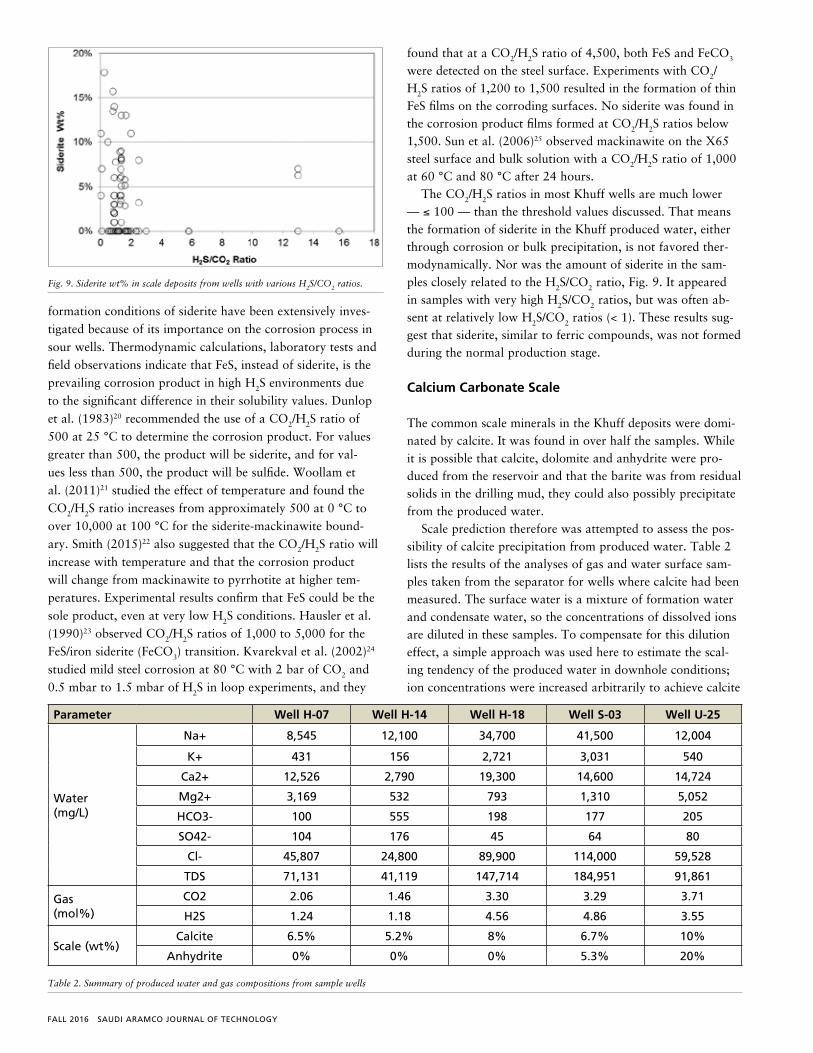
The CO2/H2S ratios in most Khuff wells are much lower — ≤ 100 — than the threshold values discussed. That means the formation of siderite in the Khuff produced water, either through corrosion or bulk precipitation, is not favored ther-modynamically. Nor was the amount of siderite in the sam-ples closely related to the H2S/CO2 ratio, Fig. 9. It appeared in samples with very high H2S/CO2 ratios, but was often ab-sent at relatively low H2S/CO2 ratios (< 1). These results sug-gest that siderite, similar to ferric compounds, was not formed during the normal production stage.
Calcium Carbonate Scale
The common scale minerals in the Khuff deposits were domi-nated by calcite. It was found in over half the samples. While it is possible that calcite, dolomite and anhydrite were pro-duced from the reservoir and that the barite was from residual solids in the drilling mud, they could also possibly precipitate from the produced water.
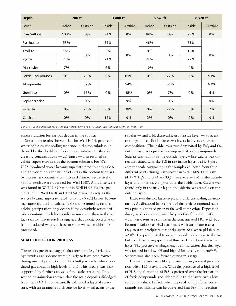
Scale prediction therefore was attempted to assess the pos-sibility of calcite precipitation from produced water. Table 2 lists the results of the analyses of gas and water surface sam-ples taken from the separator for wells where calcite had been measured. The surface water is a mixture of formation water and condensate water, so the concentrations of dissolved ions are diluted in these samples. To compensate for this dilution effect, a simple approach was used here to estimate the scal-ing tendency of the produced water in downhole conditions; ion concentrations were increased arbitrarily to achieve calcite
Fig. 9. Siderite wt% in scale deposits from wells with various H2S/CO2 ratios.
Fig. 9. Siderite wt% in scale deposits from wells with various H2S/CO2 ratios.
Parameter Well H-07 Well H-14 Well H-18 Well S-03 Well U-25
Water(mg/L)
Na+ 8,545 12,100 34,700 41,500 12,004
K+ 431 156 2,721 3,031 540
Ca2+ 12,526 2,790 19,300 14,600 14,724
Mg2+ 3,169 532 793 1,310 5,052
HCO3- 100 555 198 177 205
SO42- 104 176 45 64 80
Cl- 45,807 24,800 89,900 114,000 59,528
TDS 71,131 41,119 147,714 184,951 91,861
Gas(mol%)
CO2 2.06 1.46 3.30 3.29 3.71
H2S 1.24 1.18 4.56 4.86 3.55
Scale (wt%)Calcite 6.5% 5.2% 8% 6.7% 10%
Anhydrite 0% 0% 0% 5.3% 20%
Table 2. Summary of produced water and gas compositions from sample wells
SAUDI ARAMCO JOURNAL OF TECHNOLOGY FALL 2016
supersaturation for various depths in the tubular.
Simulation results showed that for Well H-14, produced
water had a calcite scaling tendency in the top tubulars, in-
dicated by the doubling of ion concentrations. Further in-
creasing concentrations — 2.5 times — also resulted in
calcite supersaturation at the bottom tubulars. For Well
U-25, produced water became supersaturated to both calcite
and anhydrite near the wellhead and in the bottom tubulars
by increasing concentrations 1.5 and 2 times, respectively.
Similar results were obtained for Well H-07. Anhydrite scale
was found in Well U-25 but not in Well H-07. Calcite pre-
cipitation in Well H-18 and Well S-03 was unlikely as the
waters became supersaturated to halite (NaCl) before becom-
ing supersaturated to calcite. It should be noted again that
calcite precipitation only occurs if the downhole water defi-
nitely contains much less condensation water than in the sur-
face sample. These results suggested that calcite precipitation
from produced water, at least in some wells, shouldn’t be
precluded.
SCALE DEPOSITION PROCESS
The results presented suggest that ferric oxides, ferric oxy-
hydroxides and siderite were unlikely to have been formed
during normal production in the Khuff gas wells, where pro-
duced gas contains high levels of H2S. This theory was also
supported by further analysis of the scale structure. Cross
section examination showed that the scale deposits dislodged
from the POOH tubular usually exhibited a layered struc-
ture, with an orange/reddish outside layer — adjacent to the
tubular — and a black/metallic gray inside layer — adjacent
to the produced fluid. These two layers had very different
compositions. The inside layer was dominated by FeS, and the
outside layer was primarily composed of ferric compounds.
Siderite was mainly in the outside layer, while calcite was of-
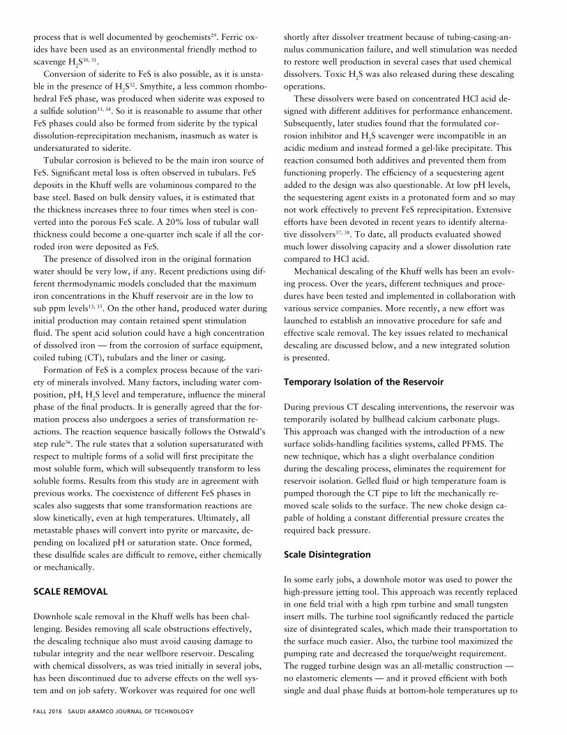
ten associated with the FeS in the inside layer. Table 3 pres-
ents the scale compositions for samples collected from four
different joints during a workover in Well U-09. In this well
(4.37% H2S and 3.46% CO2), there was no FeS in the outside
layer and no ferric compounds in the inside layer. Calcite was
found only in the inside layer, and siderite was mostly on the
outside layer.
These two distinct layers represent different scaling environ-
ments. As discussed before, part of the ferric compound scale
was possibly formed prior to the well completion. Deposition
during acid stimulation was likely another formation path-
way. Ferric ions are soluble in the concentrated HCl acid, but
become insoluble as HCl acid reacts with carbonate rocks;
they start to precipitate out of the spent acid when pH rises to
~2.026. The precipitated ferric compounds can adhere to the tu-
bular surface during spent acid flow back and form the scale
layer. The presence of akaganeite is an indication that this layer
was formed in a low pH and high chloride environment27, 28.
Siderite was also likely formed during this stage.
The inside layer was likely formed during normal produc-
tion when H2S is available. With the presence of a high level
of H2S, the formation of FeS is preferred over the formation
of ferric compounds and siderite due to the latter two’s low
solubility values. In fact, when exposed to H2S, ferric com-
pounds and siderite can be converted into FeS in a reaction
Depth 200 ft 1,800 ft 6,840 ft 8,520 ft
Layer Inside Outside Inside Outside Inside Outside Inside Outside
Iron Sulfides 100% 0% 84% 0% 98% 0% 95% 0%
Pyrrhotite 53%
0%
54%
0%
46%
0%
53%
0%Troilite 18% 3% 8% 15%
Pyrite 22% 21% 34% 23%
Marcasite 7% 6% 10% 4%
Ferric Compounds 0% 78% 0% 81% 0% 72% 0% 93%
Akaganeite
0%
59%
0%
54%
0%
65%
0%
87%
Goethite 19% 18% 7% 6%
Lepidocrocite 0% 9% 0% 0%
Siderite 0% 22% 0% 19% 0% 28% 5% 7%
Calcite 0% 0% 16% 0% 2% 0% 0% 0%
Table 3. Compositions of the inside and outside layers of scale sampledat different depths in Well U-09
FALL 2016 SAUDI ARAMCO JOURNAL OF TECHNOLOGY
process that is well documented by geochemists29. Ferric ox-ides have been used as an environmental friendly method to scavenge H2S
30, 31. Conversion of siderite to FeS is also possible, as it is unsta-
ble in the presence of H2S32. Smythite, a less common rhombo-
hedral FeS phase, was produced when siderite was exposed to a sulfide solution33, 34. So it is reasonable to assume that other FeS phases could also be formed from siderite by the typical dissolution-reprecipitation mechanism, inasmuch as water is undersaturated to siderite.
Tubular corrosion is believed to be the main iron source of FeS. Significant metal loss is often observed in tubulars. FeS deposits in the Khuff wells are voluminous compared to the base steel. Based on bulk density values, it is estimated that the thickness increases three to four times when steel is con-verted into the porous FeS scale. A 20% loss of tubular wall thickness could become a one-quarter inch scale if all the cor-roded iron were deposited as FeS.
The presence of dissolved iron in the original formation water should be very low, if any. Recent predictions using dif-ferent thermodynamic models concluded that the maximum iron concentrations in the Khuff reservoir are in the low to sub ppm levels13, 35. On the other hand, produced water during initial production may contain retained spent stimulation fluid. The spent acid solution could have a high concentration of dissolved iron — from the corrosion of surface equipment, coiled tubing (CT), tubulars and the liner or casing.
Formation of FeS is a complex process because of the vari-ety of minerals involved. Many factors, including water com-position, pH, H2S level and temperature, influence the mineral phase of the final products. It is generally agreed that the for-mation process also undergoes a series of transformation re-actions. The reaction sequence basically follows the Ostwald’s step rule36. The rule states that a solution supersaturated with respect to multiple forms of a solid will first precipitate the most soluble form, which will subsequently transform to less soluble forms. Results from this study are in agreement with previous works. The coexistence of different FeS phases in scales also suggests that some transformation reactions are slow kinetically, even at high temperatures. Ultimately, all metastable phases will convert into pyrite or marcasite, de-pending on localized pH or saturation state. Once formed, these disulfide scales are difficult to remove, either chemically or mechanically.
SCALE REMOVAL
Downhole scale removal in the Khuff wells has been chal-lenging. Besides removing all scale obstructions effectively, the descaling technique also must avoid causing damage to tubular integrity and the near wellbore reservoir. Descaling with chemical dissolvers, as was tried initially in several jobs, has been discontinued due to adverse effects on the well sys-tem and on job safety. Workover was required for one well
shortly after dissolver treatment because of tubing-casing-an-nulus communication failure, and well stimulation was needed to restore well production in several cases that used chemical dissolvers. Toxic H2S was also released during these descaling operations.
These dissolvers were based on concentrated HCl acid de-signed with different additives for performance enhancement. Subsequently, later studies found that the formulated cor-rosion inhibitor and H2S scavenger were incompatible in an acidic medium and instead formed a gel-like precipitate. This reaction consumed both additives and prevented them from functioning properly. The efficiency of a sequestering agent added to the design was also questionable. At low pH levels, the sequestering agent exists in a protonated form and so may not work effectively to prevent FeS reprecipitation. Extensive efforts have been devoted in recent years to identify alterna-tive dissolvers37, 38. To date, all products evaluated showed much lower dissolving capacity and a slower dissolution rate compared to HCl acid.
Mechanical descaling of the Khuff wells has been an evolv-ing process. Over the years, different techniques and proce-dures have been tested and implemented in collaboration with various service companies. More recently, a new effort was launched to establish an innovative procedure for safe and effective scale removal. The key issues related to mechanical descaling are discussed below, and a new integrated solution is presented.
Temporary Isolation of the Reservoir
During previous CT descaling interventions, the reservoir was temporarily isolated by bullhead calcium carbonate plugs. This approach was changed with the introduction of a new surface solids-handling facilities systems, called PFMS. The new technique, which has a slight overbalance condition during the descaling process, eliminates the requirement for reservoir isolation. Gelled fluid or high temperature foam is pumped thorough the CT pipe to lift the mechanically re-moved scale solids to the surface. The new choke design ca-pable of holding a constant differential pressure creates the required back pressure.
Scale Disintegration
In some early jobs, a downhole motor was used to power the high-pressure jetting tool. This approach was recently replaced in one field trial with a high rpm turbine and small tungsten insert mills. The turbine tool significantly reduced the particle size of disintegrated scales, which made their transportation to the surface much easier. Also, the turbine tool maximized the pumping rate and decreased the torque/weight requirement. The rugged turbine design was an all-metallic construction — no elastomeric elements — and it proved efficient with both single and dual phase fluids at bottom-hole temperatures up to
SAUDI ARAMCO JOURNAL OF TECHNOLOGY FALL 2016
350 °F. It could deliver up to 74 HP at normal conditions and run at high speeds — 2,000 rpm to 2,500 rpm — with a low torque of 150 ft/lb to 270 ft/lb at 3 barrels per minute (bpm) to 4.5 bpm, respectively, which eliminates the need to stop pumping if a stall is encountered.
Following the milling treatment, a second CT run with a pressure jetting tool was often conducted for wells with a large tubing internal diameter (ID). This run was focused on removing the remaining thin scale layer left between the mill and the ID of the tubing or liner. This additional CT run also cleaned the perforation tunnels. High impact solids — sterling beads — had also been incorporated in this stage to enhance scale removal.
Scale Clean Out
The scale removal process has been further optimized with the use of a large outside diameter CT string (2⅜”) and spe-cial high temperature foam, stable up to 325 °F. This allows higher pumping rates and annular gel velocity to improve solid suspension. These factors are important in the efficient transportation of the disintegrated solids and in minimizing the risk of a stuck CT pipe.
Downhole Performance Monitoring
The use of fiber optic enabled CT (FOECT) tools added ex-tra value to the descaling operation. The FOECT system was modified to allow a rough version to operate under harsh well conditions. This new monitoring system was successfully deployed and provided valuable information, such as bot-tom-hole pressure, temperature, annular solid concentration and different pressure regimes in front of multiple perforated intervals. Such information was used for the optimization of the jetting tool efficiency, fluids consumption, change foam quality, clean out time and scale clean out parameters.
Implementation of the new rough FOCET version also al-lowed decisions to be made with a greater degree of preci-sion, based on real-time interpretations of measured downhole data, controlling well drawdown and CT velocity as a func-tion of both scale cleanup and volumes.
Surface Solids Handling
At the surface, a new solids collecting system was imple-mented incorporating three new components:
• Auto choke devices.
• H2S separation — degasser.
• Provisions for solids separation/scale sampling and storage.
The system was built specifically for the CT descaling
operations. The equipment was commissioned after a yard test. Over 1.2 tons of scale material was successfully recovered with this new PFMS in a recent field trial.
CONCLUSIONS
Results presented in this article are as follows:
• Scale deposits in the Khuff sour gas wells have a very complex composition. They are a mixture of different types of minerals, including FeS, iron oxides, iron oxyhydroxides, siderite and other ferrous compounds, common scale minerals and elemental sulfur.
• The scale composition changes from well to well and also varies in a given well. Some deposits show a layered structure, with the inside layer (next to the producing fluid) dominated by FeS and with the outside layer (next to the tubular) primarily of iron oxides and iron oxyhydroxides, suggesting different formation environments.
• FeS scales consist of pyrrhotite, troilite, mackinawite, greigite, pyrite and marcasite. Thermodynamic stable phases — pyrrhotite, pyrite and marcasite — are more abundant than the less stable mackinawite, troilite and greigite.
• Tubular corrosion is believed to be the main iron source for FeS scales. Acid stimulation may also be a contributing factor. Dissolved iron in formation water is negligible, if any, so it is unlikely to have an impact. FeS could also be formed from the reaction of H2S with ferric ion compounds and siderite.
• The formation of FeS undergoes a series of transformation reactions. Scale composition is determined by reaction kinetics. A less stable phase, such as mackinawite, is formed initially. It converts to a more stable phase, such as greigite and pyrrhotite, and eventually to the least soluble iron disulfide: pyrite or marcasite. Formation of pyrite or marcasite is linked to localized water pH and saturation state.
• Oxidation of FeS is not a significant source for iron oxides and oxyhydroxides in the scale deposits. These ferric compounds either pre-existed on the tubular or formed during flow back of spent acid after stimulation treatment.
• FeS scale and tubular metal loss can be mitigated with downhole corrosion inhibition. Proper tubular pickling, for example, would remove the pre-existing ferric compound deposits. The corrosion inhibitor package and operation procedure, however, should be reviewed to reduce the amount of iron introduced to the well during stimulation treatment. Calcite formation should be further studied for the development of an effective
FALL 2016 SAUDI ARAMCO JOURNAL OF TECHNOLOGY
treatment strategy.
• The scale dissolvers evaluated have a much lower
dissolving power and less effect on the Khuff scales than
HCl acid. An ideal dissolver would be effective applied
to a wide range of minerals, would cause a minimum
of corrosion to downhole metallurgy, would cause no
formation damage, and would produce a minimum
amount of free H2S gas.
• Implementation of a new CT mechanical live descaling
process confirmed its great economic benefit, while
reducing the operative time and eliminating the
requirement for reservoir isolation.
ACKNOWLEDGMENTS
The authors would like to thank the management of Saudi
Aramco for permission to publish this article. Thanks are also
due to many individuals from the Research & Development
Center, the Southern Area Production Engineering
Department, EXPEC – Advanced Research Center and
Schlumberger for their contributions to this ongoing project.
A more in-depth version of this article was presented at the
SPE International Oil Field Scale Conference and Exhibition,
Aberdeen, Scotland, May 11-12, 2016.
REFERENCES
1. Choi, H.J., Warnken, D., Al-Beheiri, F.I. and Al-Bannai,
N.S.: “Field Corrosion Assessment of L80 Carbon Steel
Downhole Production Tubing at Khuff Gas Wells,” NACE
paper 06653, presented at CORROSION 2006, San Diego,
California, March 12-16, 2006.
2. Al-Tammar, J.I., Bonis, M., Salim, Y. and Choi, H.J.:
“Downhole Corrosion/Scaling Operational Experience and
Challenges in HP/HT Gas Condensate Producers,” SPE
paper 169618, presented at the SPE International Oil Field
Corrosion Conference and Exhibition, Aberdeen, U.K.,
May 12-13, 2014.
3. Kasnick, M.A. and Engen, R.J.: “Iron Sulfide Scaling and
Associated Corrosion in Saudi Arabian Khuff Gas Wells,”
SPE paper 17933, presented at the SPE Middle East Oil
Show, Bahrain, March 11-14, 1989.
4. Shoesmith, D.W., Taylor, P., Bailey, M.G. and Owen,
D.G.: “The Formation of Ferrous Monosulfide Polymorphs
during the Corrosion of Iron by Aqueous Hydrogen Sulfide
at 21 °C,” Journal of Electrochemical Society, Vol. 127,
No. 7, May 1980, pp. 1007-1015.
5. Morse, J.W., Millero, F.J., Cornwell, J.C. and Rickard, D.:
“The Chemistry of the Hydrogen Sulfide and Iron Sulfide
Systems in Natural Waters,” Earth-Science Reviews, Vol.
24, No. 1, March 1987, pp. 1-42.
6. Rickard, D.T. and Luther III, G.W.: “Chemistry of Iron Sulfides,” Chemical Reviews, Vol. 107, No. 2, January 2007, pp. 514-562.
7. Berner, R.A.: “Iron Sulfides Formed from Aqueous Solution at Low Temperatures and Atmospheric Pressure,” The Journal of Geology, Vol. 72, No. 3, May 1964, pp. 293-306.
8. Clark, A.H.: “Stability Field of Monoclinic Pyrrhotite,” Transactions of the Institutions of Mining and Metallurgy,
Section B, Vol. 75, 1966, pp. 232-235.
9. Taylor, P.: “The Stereochemistry of Iron Sulfides: A Structural Rationale for the Crystallization of Some Metastable Phases from Aqueous Solution,” American
Mineralogist, Vol. 65, Nos. 9-10, October 1980, pp. 1026-1030.
10. Hunger, S. and Benning, L.G.: “Greigite: A True Intermediate on the Polysulfide Pathway to Pyrite,” Geochemical Transactions, Vol. 8, No. 1, March 2007, pp. 1-20.
11. Benning, L.G., Wilkin, R.T. and Barnes, H.L.: “Reaction Pathways in the Fe-S System below 100 °C,” Chemical
Geology, Vol. 167, Nos. 1-2, June 2000, pp. 25-51.
12. Murowchick, J.B. and Barnes, H.L.: “Marcasite Precipitation from Hydrothermal Solutions,” Geochimica
et Cosmochimica Acta, Vol. 50, No. 12, December 1986, pp. 2615-2629.
13. Qian, G., Xia, F., Brugger, J., Skinner, W.M., Bei, J., Chen, G., et al.: “Replacement of Pyrrhotite by Pyrite and Marcasite under Hydrothermal Conditions Up to 220 °C: An Experimental Study of Reaction Textures and Mechanisms,” American Mineralogist, Vol. 96, Nos. 11-12, November 2011, pp. 1878-1893.
14. Verri, G., Sorbie, K.S., Singleton, M.A., Hinrichsen, C., Wang, Q., Chang, F.F., et al.: “Iron Sulfide Scale Management in High H2S and CO2 Carbonate Reservoirs,” SPE paper 179871, presented at the SPE International Oil Field Scale Conference and Exhibition, Aberdeen, Scotland, May 11-12, 2016.
15. Schwertmann, U., Friedl, J. and Stanjek, H.: “From Fe(III) Ions to Ferrihydrite and Then to Hematite,” Journal of Colloid and Interface Science, Vol. 209, No. 1, January 1999, pp. 215-223.
16. Cornell, R.M. and Schwertmann, U.: The Iron Oxides:
Structure, Properties, Reaction, Occurrence and Uses, 2nd edition, Wiley-VCH Publishers, New York, 2003, 703 p.
17. Riveros, P.A. and Dutrizac, J.E.: “The Precipitation of Hematite from Ferric Chloride Media,” Hydrometallurgy, Vol. 46, Nos. 1-2, August 1997, pp. 85-104.
SAUDI ARAMCO JOURNAL OF TECHNOLOGY FALL 2016
18. Wang, Q. and Zaidi, S.: “Scale Deposition in Sour Gas Wells: Scale Composition,” Materials Performance, Vol. 54, No. 4, April 2015, pp. 50-54.
19. Hamby Jr., T.W.: “Development of High-Pressure Sour Gas Technology,” Journal of Petroleum Technology, Vol. 33, No. 5, May 1981, pp. 792-798.
20. Dunlop, A.K., Hassell, H.L. and Rhodes, P.R.: “Fundamental Considerations in Sweet Gas Well Corrosion,” NACE paper 46, presented at CORROSION/83, Anaheim, California, April 18-22, 1983.
21. Woollam, R., Tummala, K., Vera, J. and Hernandez, S.: “Thermodynamic Prediction of FeCO3/FeS Corrosion Product Films,” NACE paper 11076, presented at CORROSION 2011, Houston, Texas, March 13-17, 2011.
22. Smith, S.N.: “The Carbon Dioxide/Hydrogen Sulfide Ratio — Use and Relevance,” Materials Performance, Vol. 54, No. 5, May 2015, pp. 64-67.
23. Hausler, R.H., Stegman, D.W., Cruz, C.L. and Tjandroso, D.: “Laboratory Studies on Flow-Induced Localized Corrosion in CO2/H2S Environments, II. Parametric Study on the Effect of H2S, Condensate, Metallurgy, and Flow Rate,” NACE paper 6, presented at CORROSION/90, Las Vegas, Nevada, April 23-27, 1990.
24. Kvarekval, J., Seiersten, M. and Nyborg, R.: “Corrosion Product Films on Carbon Steel in Semi-Sour CO2/H2S Environments,” NACE paper 02296, presented at CORROSION 2002, Denver, Colorado, April 7-11, 2002.
25. Sun, W., Nesic, S. and Papavinasam, S.: “Kinetics of Iron Sulfide and Mixed Iron Sulfide/Carbonate Scale Precipitation in CO2/H2S Corrosion,” NACE paper 06644, presented at CORROSION 2006, San Diego, California, March 12-16, 2006.
26. Crowe, C.W.: “Evaluation of Agents for Preventing Precipitation of Ferric Hydroxide from Spent Treating Acid,” Journal of Petroleum Technology, Vol. 37, No. 4, April 1985, pp. 691-695.
27. Atkinson, R.J., Posner, A.M. and Quirk, J.P.: “Crystal Nucleation and Growth in Hydrolyzing Iron(III) Chloride Solutions,” Clays and Clay Minerals, Vol. 25, No. 1, 1977, pp. 49-56.
28. Refait, P. and Genin, J-M.R.: “The Mechanisms of Oxidation of Ferrous Hydroxychloride Fe2(OH)3CI in Aqueous Solution: The Formation of Akaganeite vs. Goethite,” Corrosion Science, Vol. 39, No. 3, 1997, pp. 539-553.
29. Berner, R.A.: “Sedimentary Pyrite Formation: An Update,” Geochima et Cosmochimica Acta, Vol. 48, No. 4, April 1984, pp. 605-615.
30. Davidson, E., Hall, J. and Temple, C.: “An Environmentally Friendly, Highly Effective Hydrogen Sulfide Scavenger for Drilling Fluids,” SPE paper 84313, presented at the SPE Annual Technical Conference and Exhibition, Denver, Colorado, October 5-8, 2003.
31. Poulton, S.W.: “Sulfide Oxidation and Iron Dissolution Kinetics during the Reaction of Dissolved Sulfide with Ferrihydrite,” Chemical Geology, Vol. 202, Nos. 1-2, December 2003, pp. 79-94.
32. Coleman, M.L., Hedrick, D.B., Lovley, D.R., White, D.C. and Pye, K.: “Reduction of Fe(III) in Sediments by Sulfate-Reducing Bacteria,” Nature, Vol. 361, February 1993, pp. 436-438.
33. Rickard, D.T.: “Synthesis of Smythite-Rhombohedral Fe3S4,” Nature, Vol. 218, April 1968, pp. 356-357.
34. Furukawa, Y. and Barnes, H.L.: “Reactions Forming Smythite, Fe9S11,” Geochimica et Cosmochimica Acta, Vol. 60, No. 19, October 1996, pp. 3581-3591.
35. Chen, T., Wang, Q. and Chang, F.: “Understanding the Mechanisms of Iron Sulfide Scaling Deposition in Sour Gas Well,” paper presented at the 16th Middle East Corrosion Conference and Exhibition, Bahrain, February 8-11, 2016.
36. Morse, J.W. and Casey, W.H.: “Ostwald Processes and Mineral Paragenesis in Sediments,” American Journal of
Science, Vol. 288, No. 6, June 1988, pp. 537-560.
37. Wang, Q., Ajwad, H., Shafai, T. and Lynn, J.D.: “Iron Sulfide Scale Dissolvers: How Effective Are They?” SPE paper 168063, presented at the SPE Saudi Arabia Section Annual Technical Symposium and Exhibition, al-Khobar, Saudi Arabia, May 19-22, 2013.
38. Wang, Q., Shen, S., Badairy, H., Shafai, T., Jeshi, Y., Chen, T., et al.: “Laboratory Assessment of Tetrakis(hydroxymethyl)phosphonium Sulfate as Dissolver for Scales Formed in Sour Gas Wells,” International Journal of Corrosion and Scale Inhibition, Vol. 4, No. 3, 2015, pp. 235-254.
FALL 2016 SAUDI ARAMCO JOURNAL OF TECHNOLOGY
BIOGRAPHIES
Dr. Qiwei Wang works in Saudi Aramco’s Research & Development Center as a Science Specialist in oil field scale mitigation. Since joining Saudi Aramco in 2011, he has played a key role in all major scale mitigation activities and led the completion of
over 30 projects. Before joining Saud Aramco, Qiwei worked for Nalco Champion as a R&D coordinator on flow management and as a Senior Specialist on scale management. He has over 25 years of R&D and technical support experience on oil field production chemistry, scale management and water treatment.
Qiwei is an active member of the Society of Petroleum Engineers (SPE) and National Association of Corrosion Engineers (NACE). He has organized workshops, served on technical committees and chaired several conferences for both organizations.
He has authored and coauthored over 70 publications and nine U.S. patent applications.
Qiwei received his B.Eng. degree in Chemical Engineering from Taiyuan University of Science and Technology, Taiyuan, China; an M.Eng. degree in Material Sciences from Harbin Institute of Technology, Harbin, China; an M.S. degree in Chemistry from the University of Ryukyus, Okinawa, Japan; and his Ph.D. degree in Oceanography from Texas A&M University, College Station, TX.
Dr. Syed R. Zaidi has been with Saudi Aramco since 1992. His specialized area of research is the mineralogical characterization of geological samples (clay and bulk rock) by using the XRD technique. Syed is also responsible for XRD method
development and research work. He is familiar with other analytical techniques, such as XRF, SEM, FTIR, TGA, DSC and ICP.
Syed received his B.S. degree (with honors) and M.S. degree, both in Chemistry, from Aligarh Muslim University, Aligarh, India, in 1977 and 1980, respectively. In 1986, he received his Ph.D. degree in Inorganic Chemistry from Aligarh Muslim University, Aligarh, India.
Syed has published more than 20 papers in peer-reviewed journals. He is a member of the American Chemical Society (ACS) and the Society of Petroleum Engineers (SPE).
Jairo A. Leal Jauregui is a Petroleum Engineering Specialist in the Ghawar Gas Production Engineering Division of Saudi Aramco’s Southern Area Production Engineering Department. He has 23 years of experience in the oil and gas industry in areas including
well completion, workover, acid stimulation, and perforating and proppant fracturing, and he has worked with operations in Colombia, Venezuela, Argentina and Saudi Arabia.
Jairo has authored more than 20 Society of Petroleum Engineers (SPE) papers on field technology implementations, innovation and applications, fluids, stimulation and well performance.
In 1990, Jairo received his B.S. degree in Petroleum Engineering from the Universidad Industrial de Santander, Bucaramanga, Colombia, and a Specialization in Project Management from Pontificia Universidad Javeriana, Bogotá, Colombia, in 2005.
Irfan Syafii is a Senior Petroleum Engineer who joined the Ghawar Gas Production Engineering Division of Saudi Aramco’s Southern Area Production Engineering Department in 2012. Prior to joining Saudi Aramco, he worked for 16 years in various
organizations and assignments with oil and gas companies as well as service companies.
Irfan started his career as a Senior Corrosion Engineer with Corrpro in the Asia region (Indonesia, Malaysia, Brunei and China), then he continued expanding his knowledge working as a Chemical Engineer Consultant with Talisman Energy and as a Production Superintendent with Indonesia’s oil and gas company.
Additionally, Irfan worked with the Kuwait Oil Company on a water injection project, then went to work with Schlumberger in flow assurance engineering, covering projects across the Middle East, North Africa, Mexico and Ecuador.
He has comprehensive experience in well treatment, well flow assurance and production enhancement, both onshore and offshore. Overall, Irfan has been deeply involved in the design, execution and evaluation of flow assurance, well treatment especially for scale, corrosion and microbial remedies in many types of reservoirs.
In 1995, he received his B.S. degree in Chemical Engineering from the Sepuluh Nopember Institute of Technology, Surabaya, Indonesia.
Irfan is member of the Society of Petroleum Engineers (SPE).
SAUDI ARAMCO JOURNAL OF TECHNOLOGY FALL 2016
Amro E. Mukhles is a Petroleum Engineer Supervisor in the Gas Production Engineering Division of Saudi Aramco’s Southern Area Production Engineering Department. He has 11 years of experience in the oil and gas industry in areas like
production optimization, well completion, stimulation and well intervention operations as well as scale and corrosion mitigation.
Amro received his M.S. degree in Petroleum Engineering from the University of Texas at Austin, Austin, TX.
Dr. Tao Chen is a Petroleum Engineering Specialist working with the Production Technology Team of Saudi Aramco’s Exploration and Petroleum Engineering Center – Advanced Research Center (EXPEC ARC). His interests are production
chemistry and flow assurance in the oil and gas industry, specializing in oil field scale management.
Prior to joining Saudi Aramco in 2014, Tao spent more than 10 years on oil field scale management in the Eastern Hemisphere and worked at Clariant, Champion Technologies, Nalco Champion and LR Senergy in Aberdeen, U.K.
He has published nearly 60 technical publications about scale management in oil fields.
Tao received both his B.S. and M.S. degrees in Chemical Engineering from Dalian University of Technology, China, and his Ph.D. degree in Chemical Engineering from Heriot-Watt University, Edinburgh, U.K. Tao also received an MBA from Warwick University, Coventry, U.K.
Dr. Fakuen F. “Frank” Chang is a Petroleum Engineering Consultant in the Productivity Enhancement Focus Area of the Production Technology Team of Saudi Aramco’s Exploration and Petroleum Engineering Center – Advanced Research Center (EXPEC
ARC). Prior to joining Saudi Aramco in September 2012, he worked at Schlumberger for 16 years, and he was at Stimlab for 4 years before his Schlumberger career. Frank has developed many products and technologies dealing with sand control, fracturing, acidizing and perforating.
He is an inventor and recipient of 23 granted U.S. patents and the author of more than 40 Society of Petroleum Engineers (SPE) technical papers.
Frank received his B.S. degree in Mineral and Petroleum Engineering from the National Cheng Kung University, Tainan City, Taiwan; his M.S. degree in Petroleum Engineering from the University of Louisiana at Lafayette, Lafayette, LA; and his Ph.D. degree in Petroleum Engineering from the University of Oklahoma, Norman, OK.
Mauricio A. Espinosa joined Saudi Aramco in 2013 as a Senior Petroleum Engineer working in the ‘Uthmaniyah Gas Production Engineering Division of the Southern Area Production Engineering Department. Prior to joining Saudi Aramco, he worked 18
years with Schlumberger, starting as a Coiled Tubing Field Engineer and finishing as a Well Intervention Geomarket Technical Manager. Mauricio has worked in several locations, including Venezuela, Brazil, Mexico, Gabon, Saudi Arabia, the U.S. and Canada. He has comprehensive well services and production enhancement experience in land, offshore shallow water, deep-water and ultra-deep water operations. Mauricio has been extensively involved in the design, execution and evaluation of well intervention and acid stimulation treatments in carbonate and sandstone reservoirs.
In 1995, he received his B.S. degree in Electrical Engineering from Universidad del Zulia, Maracaibo, Venezuela.
Mauricio is member of the Society of Petroleum Engineers (SPE), and in 2015, he became a SPE Petroleum Engineer.