Embed Size (px)
Citation preview
D4197-EN Rev B 21 Apr 2017
Scale Link 2000 Series
Installation Manual
2 SL21xx & SL22xx Series Scale Link D4197-EN
Topcon Agriculture Americas W5527 Hwy 106
Fort Atkinson, WI 53538 USA
Tel: 800-225-7695 E-mail: [email protected]
D4197-EN SL2 Series Installation Manual LCC
All rights reserved. Reproduction of any part of this manual in any form whatsoever without Topcon
Agriculture Americas express written permission is forbidden. The contents of this manual are subject to
change without notice. All efforts have been made to assure the accuracy of the contents of this manual.
However, should any errors be detected, Topcon Agriculture Americas would greatly appreciate being
informed of these errors. The above notwithstanding, Topcon Agriculture Americas can assume no
responsibility for errors
© Copyright! 2017 Topcon Agriculture Americas, Fort Atkinson (U.S.A.).
D4197-EN SL21xx & SL22xx Series Scale Link 3
Table of Contents
1.0 INTRODUCTION ....................................................................................................... 4
2.0 TECHNICAL SPECIFICATIONS ................................................................................ 5
3.0 SAFETY DURING USE ............................................................................................. 6
3.1 Exposure to Radio Frequency ................................................................................ 6
3.2 Prior to Operation ................................................................................................... 6
3.3 Check System Before Use ..................................................................................... 6
3.4 Cleaning ................................................................................................................. 6
3.5 Battery Charging and Welding ............................................................................... 6
4.0 OVERVIEW SCALE LINK ISOBUS SYSTEM ............................................................ 7
5.0 FEATURES ................................................................................................................ 8
6.0 CONNECTOR TYPES AND FUNCTION ................................................................. 10
6.1 Connector PINOUTS ............................................................................................... 11
7.0 MOUNTING ............................................................................................................. 12
8.0 LOAD CELL CONNECTIONS .................................................................................. 13
8.1 Load Cell Setup and Connections ........................................................................ 13
9.0 DISPLAY .................................................................................................................. 13
10.0 WIRING REFERENCE INFORMATION ................................................................ 14
11.0 (SLC) SCALE LINK CONTROL CONNECTION & SERIAL CONNECTION .......... 15
12.0 OPTIONAL EQUIPMENT ...................................................................................... 16
4 SL21xx & SL22xx Series Scale Link D4197-EN
1.0 INTRODUCTION
Thank you for purchasing a Scale Link TM product.
This installation manual describes the steps necessary to install the Scale Link TM and
available connector configurations.
Scale Link TM works with several types of user displays such as Scale Link Control
(SLC2810, SLC2400) TM, Universal Terminal (ISO models ONLY), and the Touch
Screen Terminal (TST7600) Feed Mixing system. Separate manuals describe the use
and installation of the displays.
Additional Document Information listed below;
D4196 - SL2 ISO Operator’s Manual
D4195 – SLC 2810 Operator’s Manual
D4020 - Direct Access Numbers (D. A. N.)
D4204 - SL2 Technical Manual
www.digi-star.com
Introduction
D4197-EN SL21xx & SL22xx Series Scale Link 5
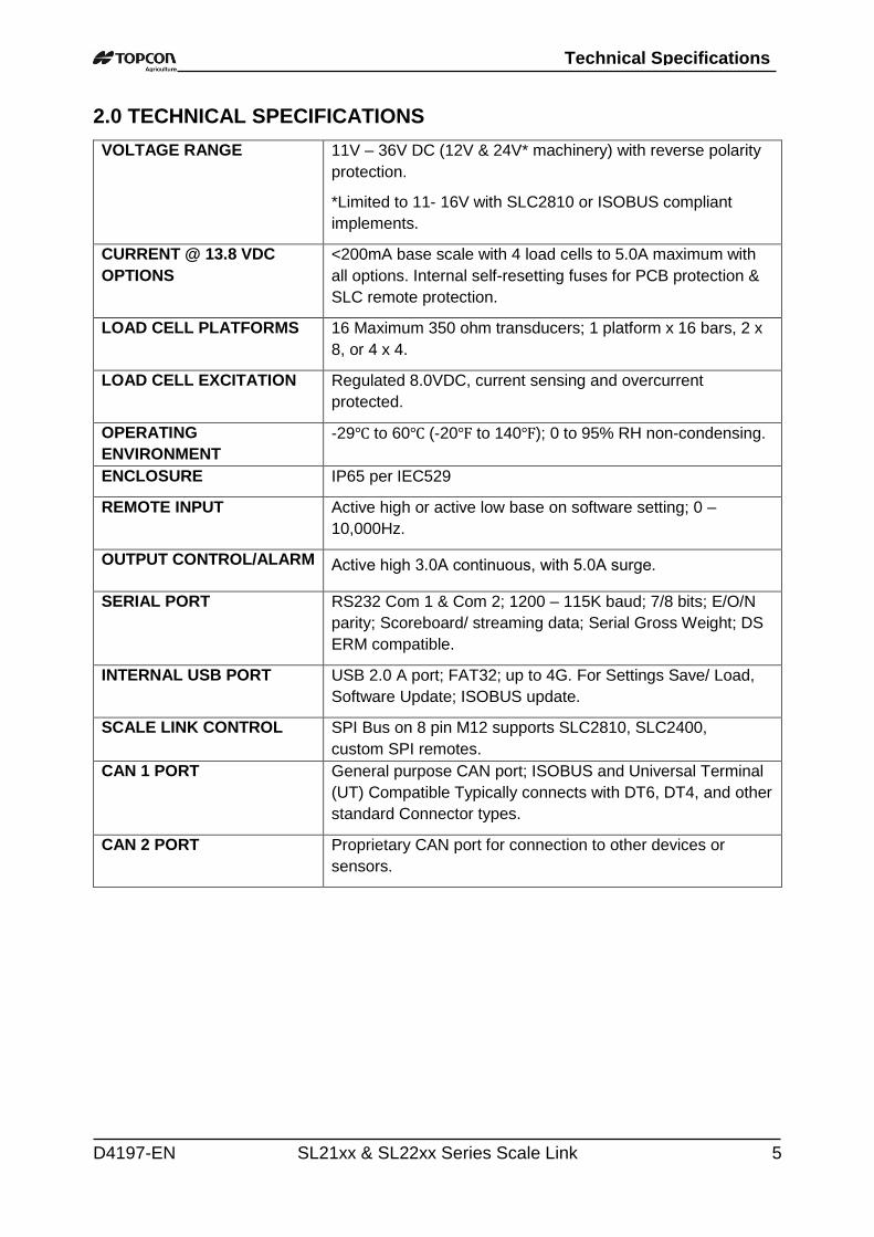
2.0 TECHNICAL SPECIFICATIONS
VOLTAGE RANGE 11V – 36V DC (12V & 24V* machinery) with reverse polarity
protection.
*Limited to 11- 16V with SLC2810 or ISOBUS compliant
implements.
CURRENT @ 13.8 VDC
OPTIONS
<200mA base scale with 4 load cells to 5.0A maximum with
all options. Internal self-resetting fuses for PCB protection &
SLC remote protection.
LOAD CELL PLATFORMS 16 Maximum 350 ohm transducers; 1 platform x 16 bars, 2 x
8, or 4 x 4.
LOAD CELL EXCITATION Regulated 8.0VDC, current sensing and overcurrent
protected.
OPERATING
ENVIRONMENT
-29℃ to 60℃ (-20℉ to 140℉); 0 to 95% RH non-condensing.
ENCLOSURE IP65 per IEC529
REMOTE INPUT Active high or active low base on software setting; 0 –
10,000Hz.
OUTPUT CONTROL/ALARM Active high 3.0A continuous, with 5.0A surge.
SERIAL PORT RS232 Com 1 & Com 2; 1200 – 115K baud; 7/8 bits; E/O/N
parity; Scoreboard/ streaming data; Serial Gross Weight; DS
ERM compatible.
INTERNAL USB PORT USB 2.0 A port; FAT32; up to 4G. For Settings Save/ Load,
Software Update; ISOBUS update.
SCALE LINK CONTROL SPI Bus on 8 pin M12 supports SLC2810, SLC2400,
custom SPI remotes.
CAN 1 PORT General purpose CAN port; ISOBUS and Universal Terminal
(UT) Compatible Typically connects with DT6, DT4, and other
standard Connector types.
CAN 2 PORT Proprietary CAN port for connection to other devices or
sensors.
Technical Specifications
6 SL21xx & SL22xx Series Scale Link D4197-EN
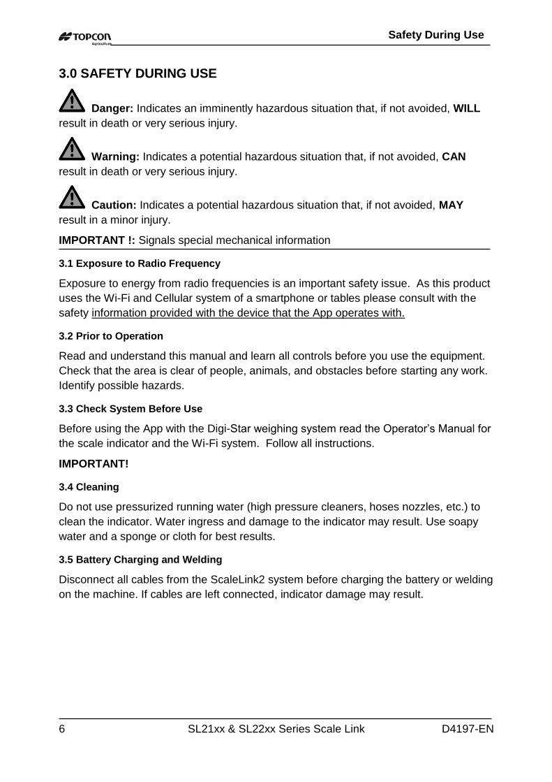
3.0 SAFETY DURING USE
Danger: Indicates an imminently hazardous situation that, if not avoided, WILL
result in death or very serious injury.
Warning: Indicates a potential hazardous situation that, if not avoided, CAN
result in death or very serious injury.
Caution: Indicates a potential hazardous situation that, if not avoided, MAY
result in a minor injury.
IMPORTANT !: Signals special mechanical information
3.1 Exposure to Radio Frequency
Exposure to energy from radio frequencies is an important safety issue. As this product
uses the Wi-Fi and Cellular system of a smartphone or tables please consult with the
safety information provided with the device that the App operates with.
3.2 Prior to Operation
Read and understand this manual and learn all controls before you use the equipment.
Check that the area is clear of people, animals, and obstacles before starting any work.
Identify possible hazards.
3.3 Check System Before Use
Before using the App with the Digi-Star weighing system read the Operator’s Manual for
the scale indicator and the Wi-Fi system. Follow all instructions.
IMPORTANT!
3.4 Cleaning
Do not use pressurized running water (high pressure cleaners, hoses nozzles, etc.) to
clean the indicator. Water ingress and damage to the indicator may result. Use soapy
water and a sponge or cloth for best results.
3.5 Battery Charging and Welding
Disconnect all cables from the ScaleLink2 system before charging the battery or welding
on the machine. If cables are left connected, indicator damage may result.
Safety During Use
D4197-EN SL21xx & SL22xx Series Scale Link 7
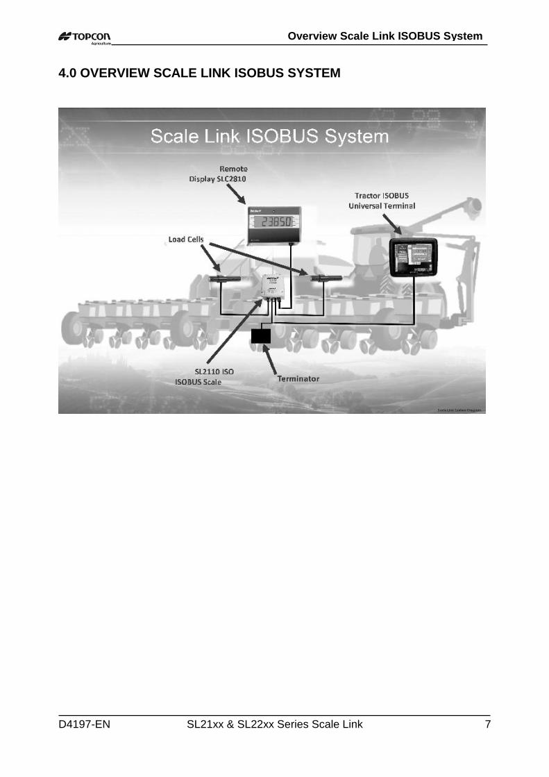
4.0 OVERVIEW SCALE LINK ISOBUS SYSTEM
Overview Scale Link ISOBUS System
8 SL21xx & SL22xx Series Scale Link D4197-EN
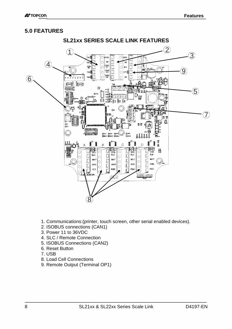
5.0 FEATURES
SL21xx SERIES SCALE LINK FEATURES
1
4
6
7
23
5
1. Communications:(printer, touch screen, other serial enabled devices). 2. ISOBUS connections (CAN1)
3. Power 11 to 36VDC 4. SLC / Remote Connection 5. ISOBUS Connections (CAN2) 6. Reset Button 7. USB
8. Load Cell Connections 9. Remote Output (Terminal OP1)
8
9
Features
D4197-EN SL21xx & SL22xx Series Scale Link 9
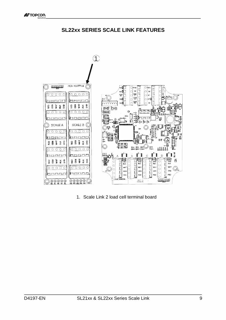
SL22xx SERIES SCALE LINK FEATURES
1. Scale Link 2 load cell terminal board
1
10 SL21xx & SL22xx Series Scale Link D4197-EN
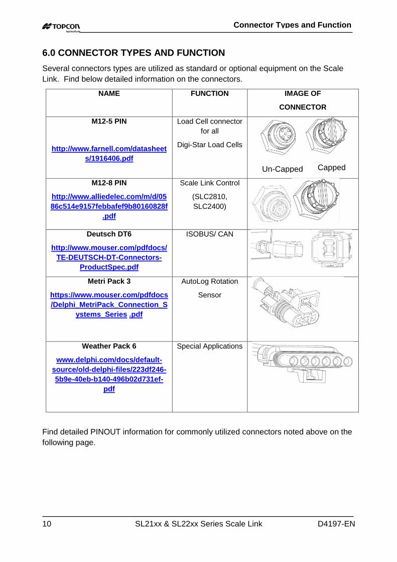
6.0 CONNECTOR TYPES AND FUNCTION
Several connectors types are utilized as standard or optional equipment on the Scale
Link. Find below detailed information on the connectors.
NAME FUNCTION IMAGE OF
CONNECTOR
M12-5 PIN
http://www.farnell.com/datasheet
s/1916406.pdf
Load Cell connector
for all
Digi-Star Load Cells
M12-8 PIN
http://www.alliedelec.com/m/d/05
86c514e9157febbafef9b80160828f
Scale Link Control
(SLC2810,
SLC2400)
Deutsch DT6
http://www.mouser.com/pdfdocs/
TE-DEUTSCH-DT-Connectors-
ProductSpec.pdf
ISOBUS/ CAN
Metri Pack 3
https://www.mouser.com/pdfdocs
/Delphi_MetriPack_Connection_S
ystems_Series .pdf
AutoLog Rotation
Sensor
Weather Pack 6
www.delphi.com/docs/default-
source/old-delphi-files/223df246-
5b9e-40eb-b140-496b02d731ef-
Special Applications
Find detailed PINOUT information for commonly utilized connectors noted above on the
following page.
Capped Un-Capped
Connector Types and Function
D4197-EN SL21xx & SL22xx Series Scale Link 11
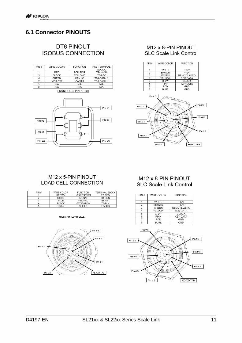
6.1 Connector PINOUTS
12 SL21xx & SL22xx Series Scale Link D4197-EN
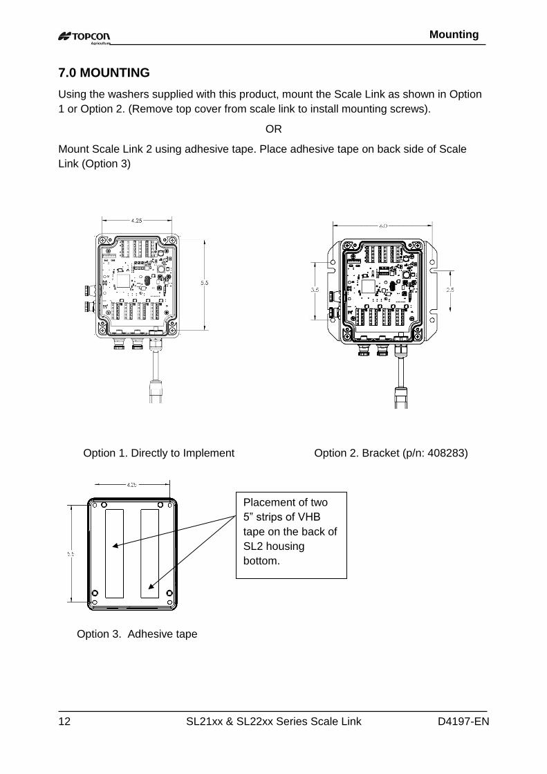
7.0 MOUNTING
Using the washers supplied with this product, mount the Scale Link as shown in Option
1 or Option 2. (Remove top cover from scale link to install mounting screws).
OR
Mount Scale Link 2 using adhesive tape. Place adhesive tape on back side of Scale
Link (Option 3)
Option 3. Adhesive tape
Option 1. Directly to Implement Option 2. Bracket (p/n: 408283)
Placement of two
5” strips of VHB
tape on the back of
SL2 housing
bottom.
Mounting
D4197-EN SL21xx & SL22xx Series Scale Link 13
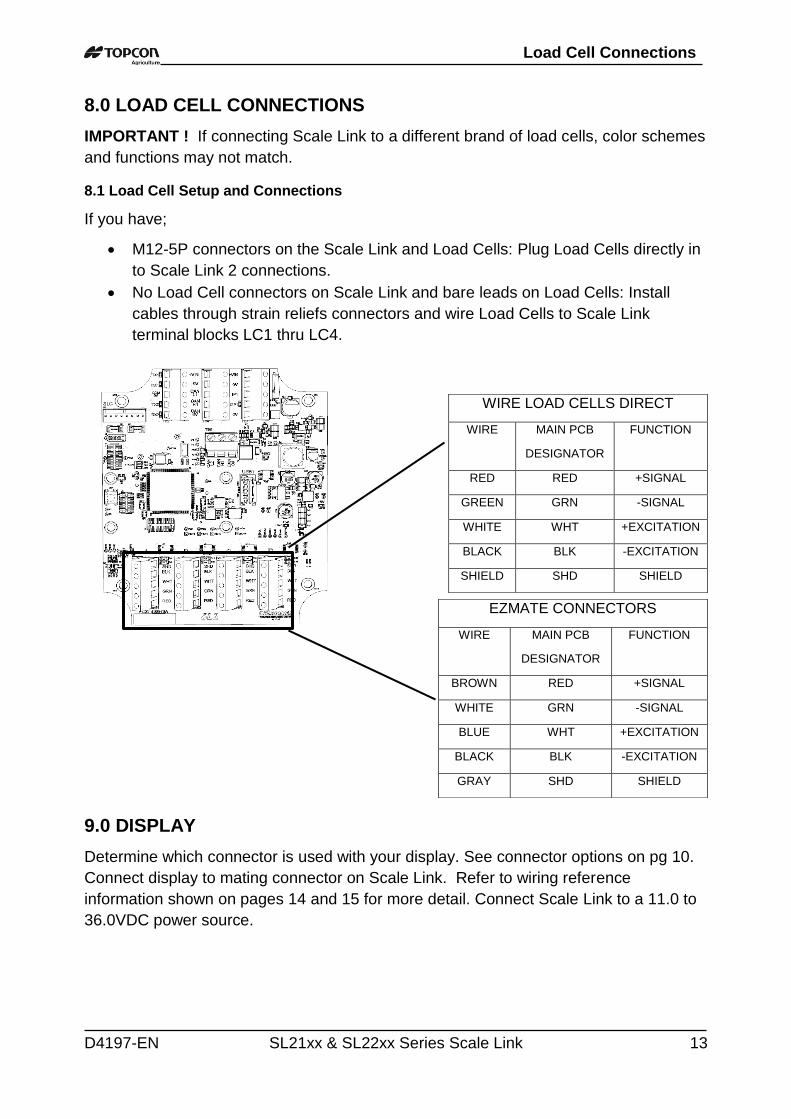
8.0 LOAD CELL CONNECTIONS
IMPORTANT ! If connecting Scale Link to a different brand of load cells, color schemes
and functions may not match.
8.1 Load Cell Setup and Connections
If you have;
M12-5P connectors on the Scale Link and Load Cells: Plug Load Cells directly in
to Scale Link 2 connections.
No Load Cell connectors on Scale Link and bare leads on Load Cells: Install
cables through strain reliefs connectors and wire Load Cells to Scale Link
terminal blocks LC1 thru LC4.
9.0 DISPLAY
Determine which connector is used with your display. See connector options on pg 10.
Connect display to mating connector on Scale Link. Refer to wiring reference
information shown on pages 14 and 15 for more detail. Connect Scale Link to a 11.0 to
36.0VDC power source.
WIRE LOAD CELLS DIRECT
WIRE MAIN PCB
DESIGNATOR
FUNCTION
RED RED +SIGNAL
GREEN GRN -SIGNAL
WHITE WHT +EXCITATION
BLACK BLK -EXCITATION
SHIELD SHD SHIELD
EZMATE CONNECTORS
WIRE MAIN PCB
DESIGNATOR
FUNCTION
BROWN RED +SIGNAL
WHITE GRN -SIGNAL
BLUE WHT +EXCITATION
BLACK BLK -EXCITATION
GRAY SHD SHIELD
Load Cell Connections
14 SL21xx & SL22xx Series Scale Link D4197-EN
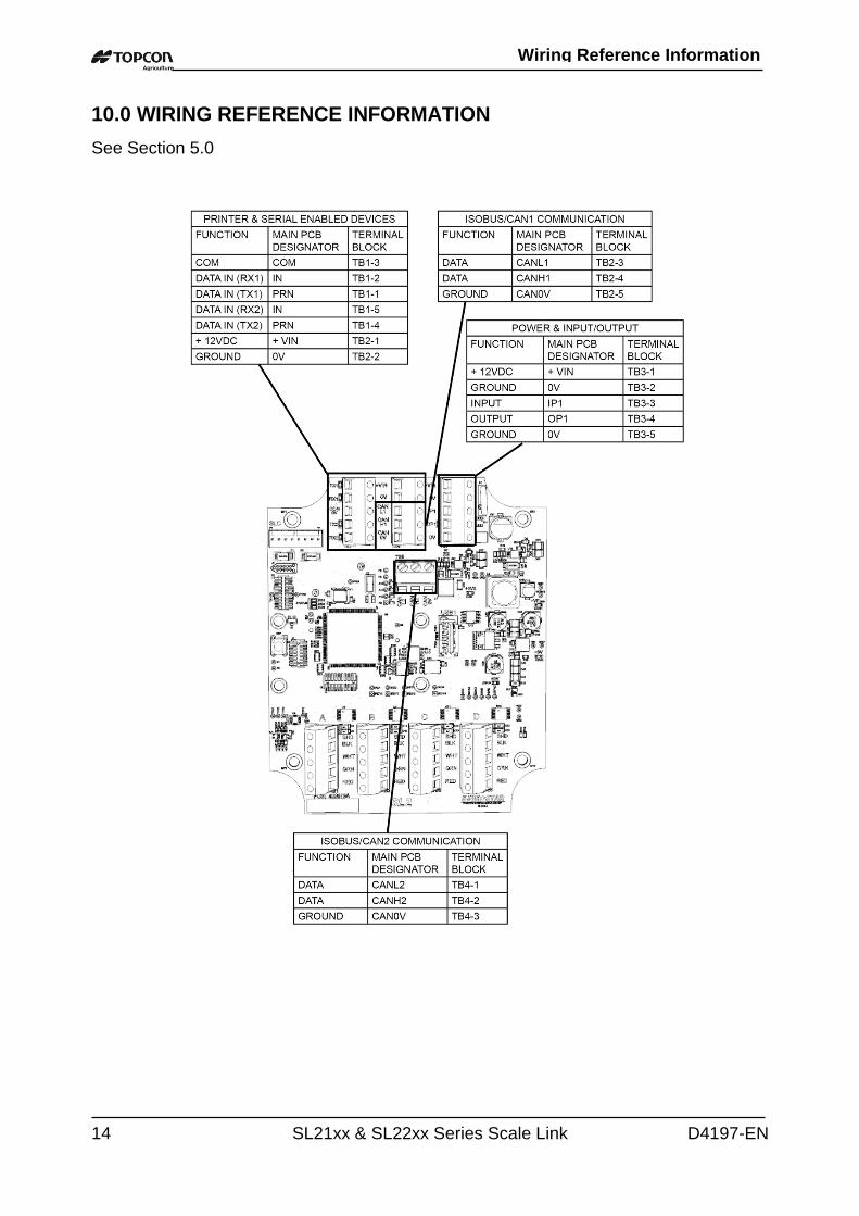
10.0 WIRING REFERENCE INFORMATION
See Section 5.0
Wiring Reference Information
D4197-EN SL21xx & SL22xx Series Scale Link 15
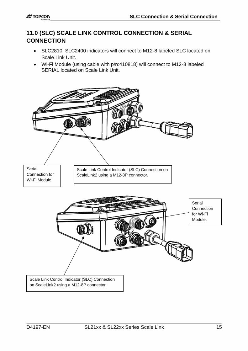
11.0 (SLC) SCALE LINK CONTROL CONNECTION & SERIAL
CONNECTION
SLC2810, SLC2400 indicators will connect to M12-8 labeled SLC located on
Scale Link Unit.
Wi-Fi Module (using cable with p/n:410818) will connect to M12-8 labeled SERIAL located on Scale Link Unit.
Serial
Connection for
Wi-Fi Module.
Scale Link Control Indicator (SLC) Connection on
ScaleLink2 using a M12-8P connector.
Scale Link Control Indicator (SLC) Connection
on ScaleLink2 using a M12-8P connector.
Serial
Connection
for Wi-Fi
Module.
SLC Connection & Serial Connection
16 SL21xx & SL22xx Series Scale Link D4197-EN
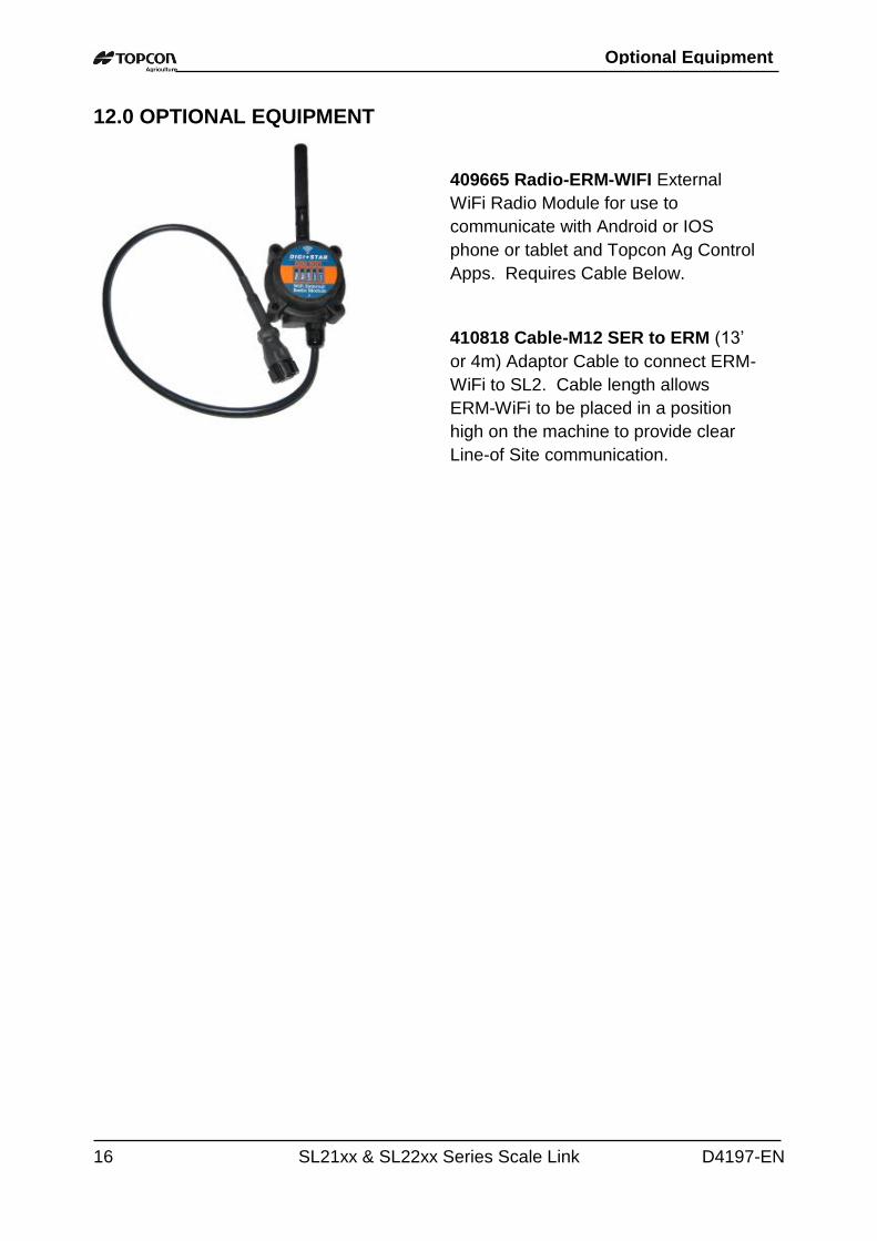
12.0 OPTIONAL EQUIPMENT
409665 Radio-ERM-WIFI External
WiFi Radio Module for use to
communicate with Android or IOS
phone or tablet and Topcon Ag Control
Apps. Requires Cable Below.
410818 Cable-M12 SER to ERM (13’
or 4m) Adaptor Cable to connect ERM-
WiFi to SL2. Cable length allows
ERM-WiFi to be placed in a position
high on the machine to provide clear
Line-of Site communication.
Optional Equipment