Embed Size (px)
Citation preview

Scale Readout Manual
Version 8.70EAG_APPC.DOC 03/15/02 1:26 PM
Scale Readout Manual
Version 8.70 C-2EAG_APPC.DOC 07/03/01 1:40 PM
Appendix C
Scale Readout Manual

Scale Readout Manual Introduction
Version 8.70EAG_APPC.DOC 03/15/02 1:26 PM
C-1
Appendix C: Scale Readout ManualThe Scale Readout Unit is a digital weight indicator that may be used for 1 to 3 scales.The interface to each scale may be load cells or scale pots (dial potentiometers). A 5digit LED display is provided for each scale. Along with each display is a set of 3pushbuttons that provide all of the control functions for the display.
The unit also provides an analog output voltage for each scale. These signals may beused by a batching computer to control the scale weighing operation.
Some of the features include password protection of all calibration data, motiondetection, overload indication (weight exceeding 105% of capacity), digital filtering forstable readings, and output simulation for ease of calibrating external controllers.
This manual includes information describing the normal operation as well as all stepsrequired to setup and calibrate the unit. Included is a Menu Map diagram that may beused as a guide to access the available functions.

Scale Readout Manual Operation
Version 8.70EAG_APPC.DOC 03/15/02 1:26 PM
C-2
Readout Menu Map
Note: 1. This is the Weight Added to the scale forcalibration.
2. Enter the Old password here.
3. Enter the New password here.
NormalWeightDisplay
“CAL” “SEtUP” “dIAG” “r1 _ 12”
“PASS”
“XXXXX”
“PASS”
“XXXXX”
“ZErO” “Count” “Out” “rEAL” “rAtE” “SPAn” “CALC” “PASS” ConFG“FULL” “GrAd” “CAP”
“-SET-” XXXXX coounts XXXXX weight weight counts XXXXX XXXXX config
counts XXXXX
XXXXX XXXXX
Scale Readout Manual Calibration
Version 8.70EAG_APPC.DOC 03/15/02 1:26 PM
C-3
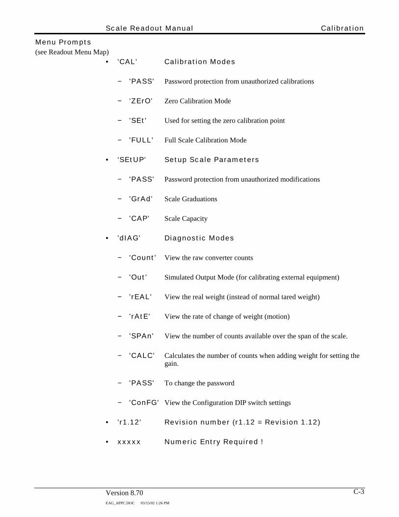
Menu Prompts(see Readout Menu Map)
• 'CAL' Calibration Modes
− 'PASS' Password protection from unauthorized calibrations
− ‘ZErO' Zero Calibration Mode
− 'SEt' Used for setting the zero calibration point
− 'FULL' Full Scale Calibration Mode
• ‘SEtUP' Setup Scale Parameters
− 'PASS' Password protection from unauthorized modifications
− 'GrAd' Scale Graduations
− 'CAP' Scale Capacity
• 'dIAG' Diagnostic Modes
− 'Count' View the raw converter counts
− 'Out' Simulated Output Mode (for calibrating external equipment)
− 'rEAL' View the real weight (instead of normal tared weight)
− 'rAtE' View the rate of change of weight (motion)
− 'SPAn' View the number of counts available over the span of the scale.
− 'CALC' Calculates the number of counts when adding weight for setting thegain.
− 'PASS' To change the password
− 'ConFG' View the Configuration DIP switch settings
• 'r1.12' Revision number (r1.12 = Revision 1.12)
• xxxxx Numeric Entry Required !

Scale Readout Manual Operation
Version 8.70EAG_APPC.DOC 03/15/02 1:26 PM
C-4
Pushbuttons• Normal Weight Display Mode
− ZERO used to re-zero the scale weight (limited to a range of -2% to+5% from the zero calibration set point).
− SELECT used to enter the calibration modes.
− ASTERISK used to view the actual weight (weight calculated from zerocalibration set point) for approximately 1 to 2 seconds.
• Numeric Entry Mode
− ZERO used as an escape key to exit without changing any data.
− SELECT used to select digit to edit.
− ASTERISK used to enter changed data.
− To CHANGE Number:
− Press the SELECT button to select which digit to change. As a digitbecomes editable, it begins blinking.
− To increment the digit, press the ASTERISK button. This will increment thedigit from 0 to 9, then back to 0 if pressed repeatedly.
− When final number is displayed, press the SELECT button until no digits areblinking.
− To ENTER Number:
− To enter the new number, press the ASTERISK button (with no digitsblinking).
− To EXIT (without saving changes):
− Press the ZERO button to Escape back to the normal weight display mode.

Scale Readout Manual Calibration
Version 8.70EAG_APPC.DOC 03/15/02 1:26 PM
C-5
• Other Modes
− ZERO used as an escape key to exit any function without changing anydata.
− SELECT used to select between various functions.
− ASTERISK used as an enter key to enter a lower level in the menu structure.

Scale Readout Manual Operation
Version 8.70EAG_APPC.DOC 03/15/02 1:26 PM
C-6
Normal Weight Display ModeThe normal weight display mode has the basic function of displaying the weight on thescale. This weight is displayed in graduations (grads) of typically 0.1% of scale capacity(i.e. - 10 lbs for a 10,000 lb scale). The displayed weight is also adjusted for any taredweight. Additional information available in this mode:
1. The decimal point at the right side of the displayed number serves as an annunciatorof motion detection. If motion detection is enabled (see Configuration SwitchSettings), the LED will be on when motion is sensed.
2. If the ASTERISK button is pressed, the 'real' weight is displayed (that is, the weightcalculated from the calibrated zero set point). The real weight is displayed for 1 to 2seconds. During this time, all 5 of the decimal points will be illuminated.
3. If the range of the scale has been exceeded (105% of scale capacity), the prompt willindicate the overload condition 'oLOAd' (flashing display).
If above the upper limit of the display, the indication will be 'EEEEE'. If below thelower limit of the display, the indication will be '-EEEE'. In either case, the displaywill be flashing.

Scale Readout Manual Calibration
Version 8.70EAG_APPC.DOC 03/15/02 1:26 PM
C-7
Initial Hardware Setup1. Make sure the wiring of each scale cable is correct. Refer to the enclosed cable
drawings for the proper wiring (for load cell or scale pot connections).
2. Open the rear door of the enclosure for access to the printed circuit board as shownin Figure 2.
3. Each of the 3 scale channels uses a slide switch to select the use of either load cells(LC) or scale pots (SP). Move this switch to the proper setting (up for load cells ordown for scale pots). Refer to Figure 2.
4. For each channel there is a rotary switch with a knob on top labelled 0 - 9. This isprovided to adjust the gain of the circuit.
Knob Setting Gain Use
0 1 For Scale Pots
1 - 7 100 - 700 For Load Cells
8, 9 N/U Not used
For load cells, the knob should be initially set to position 1. On the side of the rotaryswitch housing there is a mark that points to the number setting on the knob. Referto Figure 2 below. Additional gain adjustment is provided by jumpers W1, W2,W3, one for each of the respective scales. When the jumper is installed, the gain isreduced by 1/3 (one-third). This allows for more precise gain adjustment when usingload cells.
5. Connect the scale cables to the respective channel inputs and turn on power.
Figure 2- Calibration Controls (as viewed from rear of display unit). Shown set upfor scale pots with Gain pointing to zero (0).
W1 W2 W3Gain Gain Gain
1 2 3 4 5 6 7 8
ON
OFFConfig
LC LC LC
SP SP SP
Scale Input Scale Input Scale Input Analog Scale Ouputs(Water) (Cement) (Aggregate) (To Eagle)
1 0 9 2 8 3 7 4 5 6
1 0 9 2 8 3 7 4 5 6
1 0 9 2 8 3 7 4 5 6

Scale Readout Manual Calibration
Version 8.70EAG_APPC.DOC 07/03/01 1:40 PM
C-8
Initial Calibration Setup1. Refer to the Readout Menu Map diagram when stepping through the menu.
2. Press the SELECT button to enter the menu structure. The first prompt is 'CAL'which allows entering the calibration area.
3. To get a feel for the menus at this time, press the SELECT button a few times andsee the prompts rotate between the possible settings.
4. Press the SELECT button until the prompt 'SEtUP' is displayed. This allowschanging the setup parameters. Enter this menu by pressing the ASTERISK button.The prompt should now read 'GrAd'.
Note: If the display prompt reads 'PASS', then a passwordneeds to be entered at this point. See “Password”section.
5. When 'GrAd' is displayed, press the ASTERISK button to enter the mode to changethe graduation size. The present value is now displayed.
6. To change this value, press the SELECT button to select one digit at a time to bechanged. The editable digit is blinking. As the digit is blinking, press theASTERISK button to increment the digit from 0 to 9, then back to 0.
When all digits are correct, press the ASTERISK button to enter the value (when nodigits are blinking).
Note: The display will then return to the normal weightdisplay mode.
Note: Whenever stepping through the menus or changingvalues, if the ZERO button is pressed, the display willreturn to the normal weight display mode, and nochanges will be made!
7. Repeat the process of pressing the SELECT button and stepping into the 'SEtUP'
menu. Next, press the ASTERISK button. The display should now read 'GrAd'.Then press the SELECT button and the display should read 'CAP'. Next, press theASTERISK button to enter the mode to change the value of scale CAPacity. As withthe graduations, the present value is now displayed. Change the value by pressingthe SELECT button and save it as described in step 6 (which set the graduation size).
Now that the initial setup is complete, we need to adjust the gain if using load cells.
Scale Readout Manual Calibration
Version 8.70EAG_APPC.DOC 03/15/02 1:26 PM
C-9
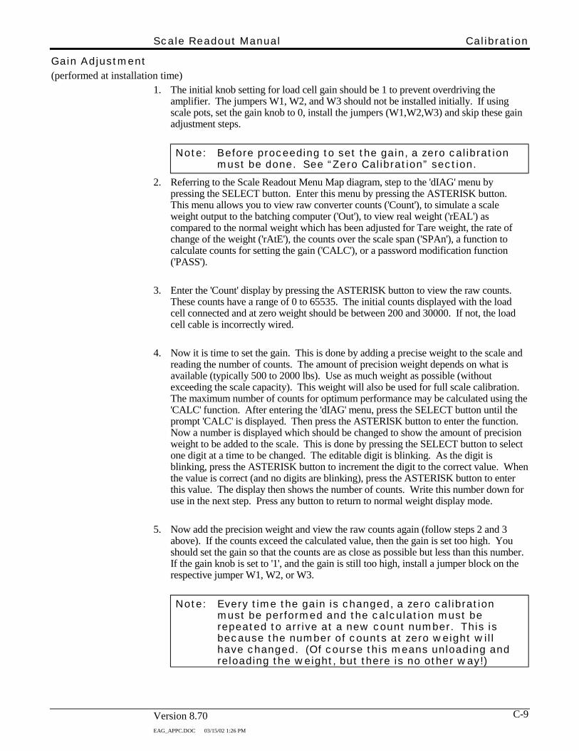
Gain Adjustment(performed at installation time)
1. The initial knob setting for load cell gain should be 1 to prevent overdriving theamplifier. The jumpers W1, W2, and W3 should not be installed initially. If usingscale pots, set the gain knob to 0, install the jumpers (W1,W2,W3) and skip these gainadjustment steps.
Note: Before proceeding to set the gain, a zero calibrationmust be done. See “Zero Calibration” section.
2. Referring to the Scale Readout Menu Map diagram, step to the 'dIAG' menu bypressing the SELECT button. Enter this menu by pressing the ASTERISK button.This menu allows you to view raw converter counts ('Count'), to simulate a scaleweight output to the batching computer ('Out'), to view real weight ('rEAL') ascompared to the normal weight which has been adjusted for Tare weight, the rate ofchange of the weight ('rAtE'), the counts over the scale span ('SPAn'), a function tocalculate counts for setting the gain ('CALC'), or a password modification function('PASS').
3. Enter the 'Count' display by pressing the ASTERISK button to view the raw counts.These counts have a range of 0 to 65535. The initial counts displayed with the loadcell connected and at zero weight should be between 200 and 30000. If not, the loadcell cable is incorrectly wired.
4. Now it is time to set the gain. This is done by adding a precise weight to the scale andreading the number of counts. The amount of precision weight depends on what isavailable (typically 500 to 2000 lbs). Use as much weight as possible (withoutexceeding the scale capacity). This weight will also be used for full scale calibration.The maximum number of counts for optimum performance may be calculated using the'CALC' function. After entering the 'dIAG' menu, press the SELECT button until theprompt 'CALC' is displayed. Then press the ASTERISK button to enter the function.Now a number is displayed which should be changed to show the amount of precisionweight to be added to the scale. This is done by pressing the SELECT button to selectone digit at a time to be changed. The editable digit is blinking. As the digit isblinking, press the ASTERISK button to increment the digit to the correct value. Whenthe value is correct (and no digits are blinking), press the ASTERISK button to enterthis value. The display then shows the number of counts. Write this number down foruse in the next step. Press any button to return to normal weight display mode.
5. Now add the precision weight and view the raw counts again (follow steps 2 and 3above). If the counts exceed the calculated value, then the gain is set too high. Youshould set the gain so that the counts are as close as possible but less than this number.If the gain knob is set to '1', and the gain is still too high, install a jumper block on therespective jumper W1, W2, or W3.
Note: Every time the gain is changed, a zero calibrationmust be performed and the calculation must berepeated to arrive at a new count number. This isbecause the number of counts at zero weight willhave changed. (Of course this means unloading andreloading the weight, but there is no other way!)

Scale Readout Manual Calibration
Version 8.70EAG_APPC.DOC 07/03/01 1:40 PM
C-10
Zero Calibration1. Remove all weight from the scale before performing this calibration.
2. Referring to the Scale Readout Menu Map diagram, step to the 'CAL' menu bypressing the SELECT button. Enter this menu by pressing the ASTERISK button.
Note: If the display prompt reads 'PASS', then a passwordneeds to be entered at this point. See “Password”section.
3. Now the prompt should read 'ZErO'. Press the ASTERISK button to enter the zerocalibration mode. Now the prompt reads '-SEt-'. Be sure the scale is empty thenpress the ASTERISK button. Now the zero calibration is automatically performed,the data is saved, and the display returns to the normal weight display mode.

Scale Readout Manual Calibration
Version 8.70EAG_APPC.DOC 03/15/02 1:26 PM
C-11
Full Scale Calibration1. This function is called full scale calibration, but since we can only hang a small
percentage of the full scale weight (precision weights typically range from 500 to2000 lbs), this is the most accurate point for calibration. Use as much weight aspossible (without exceeding the scale capacity). Load the scale now with theprecision weight.
2. Referring to the Scale Readout Menu Map diagram, step to the 'CAL' menu bypressing the SELECT button. Enter this menu by pressing the ASTERISK button.
Note: If the display prompt reads 'PASS', then a passwordneeds to be entered. See “Password” section.
3. Press the SELECT button again until the prompt reads 'FULL'. Press the ASTERISKbutton to enter the full scale calibration mode. Now the last entered value of fullscale calibration weight is displayed. Change this value to the amount added to thescale. This is done by pressing the SELECT button to select one digit at a time to bechanged. The editable digit is blinking. As the digit is blinking, press theASTERISK button to increment the digit to the correct value.
When the value is correct (and no digits are blinking), press the ASTERISK buttonto enter this value. Now the calculations are automatically performed, the data issaved, and the display returns to the normal weight display mode.
4. Check the calibration (and linearity of the scale system) by sequentially removingthe precision weight, adding approximately that amount of material to the scale, thenadd the precision weight again. The graduation size can be changed at any timewithout affecting the calibration, so you may wish to reduce this number whenchecking the accuracy of the scale.

Scale Readout Manual Calibration
Version 8.70EAG_APPC.DOC 07/03/01 1:40 PM
C-12
Simulated Outputs1. The readout supplies an analog output signal to a batching control system for each of
the 3 scales. The simulated mode is used to calibrate the batching control to theoutput signals by simulating any value of weight from zero to full scale capacity.This allows the batching control to be calibrated any time after the readout has beencalibrated to the scale.
2. Referring to the Scale Readout Menu Map diagram, step to the 'dIAG' menu bypressing the SELECT button. Enter this menu by pressing the ASTERISK button.
3. Press the SELECT button until the prompt reads 'Out'. Press the ASTERISK buttonto enter the output simulation mode. Now the last entered value of simulated weightis displayed. Change this value to the desired simulated weight. This is done bypressing the SELECT button to select one digit at a time to be changed. The editabledigit is blinking. As the digit is blinking, press the ASTERISK button to incrementthe digit to the correct value.
When the value is set as desired (and no digits are blinking), press the ASTERISKbutton to send this value out the analog output port. This simulates the value thatwill be sent out when the scale is reading this same weight. If an amount greaterthan the scale capacity is entered, the display reads 'HiErr' for one second and thenreturns to the normal weight display mode.
To return to the normal weight display mode, press any button.
Note: Be sure to exit the Simulate Output mode beforeusing the scale.

Scale Readout Manual Miscellaneous
Version 8.70EAG_APPC.DOC 07/03/01 1:40 PM
C-13
Error MessagesThe following error messages may be encountered during calibration of the readoutboard. The messages are only displayed when data is entered from the front panelpushbuttons.
• 'LoErr'A Low Error indicates that with the present gain and calibration adjustment the scalecannot register 5 graduations below zero. (Either gain is too low, or the cable iswired incorrectly)
• 'HiErr'A High Error indicates that with the present gain and calibration adjustment the scalecannot register 105% of full scale capacity. (Gain is too high)
• 'GAin'A Gain Error indicates that with the present gain setting, the number of counts overthe scale range is less than 32000. This will not give optimum performance. (Gainis too low). The actual number of counts over the span can be read by using theSpan function in the Diagnostic menu.
• 'rAtE'A Rate Error indicates that there is too much motion on the scale (rate of change ofthe weight) to perform an accurate calibration. Motion detection is enabled byselecting the proper DIP switch settings. The actual motion may be viewed byentering the Rate function in the Diagnostic menu.
• ‘Error’An ‘Error’ error can be caused by the following:• If the counts when Zero Calibrating are less than 600.• If the counts when Zero Calibrating are greater than the counts when the scale is
at 75% of max capacity (according to previous calibration).• If the counts when Full Scale calibrating are less than 200 counts above the Zero
calibrate point.

Scale Readout Manual Miscellaneous
Version 8.70EAG_APPC.DOC 07/03/01 1:40 PM
C-14
Passwords When entering the 'CAL' menu or the 'SEtUP' menu, a password entry is required (unlesspasswords have been bypassed or locked out).
• EntryIf a password entry is required, the display reads 'PASS'. At this point press theASTERISK key to enter this mode. Now the display should read '0'.
To enter a password, change this value to correct password number. This is done bypressing the SELECT button to select one digit at a time to be changed. The editabledigit is blinking. As the digit blinks, press the ASTERISK button to increment thedigit to the correct value.
When the value is correct (and no digits are blinking), press the ASTERISK buttonto enter this value. If the number entered is not correct, the display will return to thenormal weight display mode. If correct, the prompt will then display either 'ZErO' or'GrAd'. At this point any of the calibration functions or setup functions may beperformed, respectively.
• BypassThis password entry steps are bypassed if the password is set to zero. Also, after thecorrect password has been entered once, subsequent calibrations do not require thepassword to be entered again (until power is turned off).
• Lock-OutThe entire calibration menu is not available if an optional lock-out switch is turnedon (or if CONFIG switch position 8 is ON. See Scale Lock Out). If locked out,password modifications are disabled also.
• ModifyTo modify the password, step to the 'dIAG' menu by pressing the SELECT button(refer to the Scale Readout Menu Map). Enter this menu by pressing the ASTERISKbutton. Press the SELECT button until the prompt shows 'PASS', then press theASTERISK button to enter the modify function.
First, a random number is displayed. Change this number to the old password (ifunknown, call the factory for a temporary password). This is done by pressing theSELECT button to select one digit at a time to be changed. The editable digit isblinking. As the digit blinks, press the ASTERISK button to increment the digit tothe correct value.
When the value is correct (and no digits are blinking), press the ASTERISK buttonto enter this value. After entering this password, the old password is displayed againand should be changed to the new password.
Note: Cycle power when done to establish the passwordprotection.

Scale Readout Manual Miscellaneous
Version 8.70EAG_APPC.DOC 07/03/01 1:40 PM
C-15
Configuration Switch SettingsThe CONFIG DIP switch as shown in Figure 2 controls various functions. There is anentry in the diagnostic area that allows the user to view the switch settings from the frontpanel display. This is needed when the back cover plate is sealed or otherwiseinaccessible.
To view the settings from the display, enter the 'dIAG' menu (refer to the Scale ReadoutMenu Map diagram). Press the SELECT button until the prompt reads 'ConFG'. Thenpress the ASTERISK key to display the configuration. There is a series of 8 lights andeach represent a corresponding DIP switch position (1 to 8, left to right). Each light canbe up or down, just as the DIP switch appears when viewed from the rear of the unit (UP= ON, DOWN = OFF).
If a switch setting is changed, the new function is activated when power is cycled.
The functions presently available are listed as follows :
• Motion Detection
Disabled Motion = +/-1 Grad
Config Config
+/-3 Grads +/-5 Grads
Config Config
When motion is detected, the decimal point on the far right side of the display willbe ON. This gives a constant indication of when motion is present. The amount ofmotion may be viewed as a rate of change in units (i.e. - pounds). This is found inthe diagnostic menu as 'rAtE' (see Scale Readout Menu Map). When this mode isentered, the rate of change (+/-) is displayed until one of the 3 keys is pressed.
Scale calibrations are affected by motion detection. If motion is detected whenattempting a zero calibration, or upon entering the full scale calibration mode, orwhen pressing the tare button, the action will not be performed. The error message'rAtE' will be displayed.
ON
OFF
1 2 3 4 5 6 7 8
ON
OFF
1 2 3 4 5 6 7 8
ON
OFF
1 2 3 4 5 6 7 8
ON
OFF
1 2 3 4 5 6 7 8

Scale Readout Manual Miscellaneous
Version 8.70EAG_APPC.DOC 07/03/01 1:40 PM
C-16
• Digital Filtering
Filtering Disabled Low
Config Config
Medium High
Config Config
Digital filtering is active in the readout if the appropriate DIP switches are set. Thefigure above illustrates the switch settings necessary to get varying amounts offiltering. Use care when setting for medium to high filtering because it greatlyincreases the response time of the scale .
• Scale Lock Out
Disabled Enabled
This feature is used to lock out the user from making unauthorized calibrationchanges. It also prevents the user from changing the scale capacity (which in turnchanges calibrations).
Scale Calibration Sealing MethodDisabling the DIP switch shown above allows the unit to be calibrated. There is a metalplate that must be removed to access the DIP switches. The plate is attached with 2screws that have holes through them. A lead wire seal can be used to restrict access tothese switches (refer to the diagram on the following page).
ON
OFF
1 2 3 4 5 6 7 8ON
OFF
1 2 3 4 5 6 7 8
ON
OFF
1 2 3 4 5 6 7 8ON
OFF
1 2 3 4 5 6 7 8
ON
OFF
1 2 3 4 5 6 7 8ON
OFF
1 2 3 4 5 6 7 8

Scale Readout Manual Miscellaneous
Version 8.70EAG_APPC.DOC 07/03/01 1:40 PM
C-17
To assist you in managing your security we have included this password form. Removeit and copy freely and store the filled in table in a secure location.
Day Month Year Password category Person(s) issued to:5 digits num.
password
__ __ __ __ __ __ Setup and Calibration __ __ __ __ __


![REVISION Q Q RFXXX-XXXXX-XXXXX-XXXXsuddendocs.samtec.com/prints/rfxxx-xxxxx-xxxxx-xxxx-mkt.pdf · designed & dimensioned in millimeters[inches] q do not scale from this print rfxxx-xxxxx-xxxxx-xxxx](https://img.pdfslide.net/doc/110x75/605e4fd9ced18c5ee459dcd2/revision-q-q-rfxxx-xxxxx-xxxxx-designed-dimensioned-in-millimetersinches.jpg)