Embed Size (px)
Citation preview
SCALING UP BIOMASS GASIFIER USE: APPLICATIONS, BARRIERS AND INTERVENTIONS
Debyani Ghosh† Ambuj Sagar†
V. V. N. Kishore§
† Science, Technology, and Public Policy Program Belfer Center for Science and International Affairs
John F. Kennedy School of Government Harvard University
§ Biomass Energy Technology Applications The Energy and Resources Institute (TERI)
and
TERI School for Advanced Studies
November 2003
2
ACKNOWLEDGEMENTS This paper draws, in part, on research carried out under the Energy Technology Innovation Project in the Science, Technology, and Public Policy Program at the Belfer Center for Science and International Affairs, Kennedy School of Government, Harvard University, with support from the Energy Foundation, the Heinz Family Foundation, the William and Flora Hewlett Foundation, the David and Lucile Packard Foundation, and the Winslow Foundation. We would like to thank the numerous researchers, practitioners, and policy-makers in India (listed in Annexure 4) who freely shared information as well as their views and insights during the course of interviews with them. We also benefited significantly from comments received during a presentation at the World Bank of a preliminary version of this work. Finally, we would like to thank Ajay Mathur for his numerous suggestions, comments, and other helpful inputs that have added greatly to this paper. Of course, the final responsibility for the document, and the interpretations offered therein, lies with us.
3
TABLE OF CONTENTS
EXECUTIVE SUMMARY ......................................................................................................... 4
1. B IOMASS GASIFICATION FOR RURAL DEVELOPMENT ........................................................ 8
2. DEVELOPMENT AND DISSEMINATION OF BIOMASS GASIFIERS IN INDIA.......................... 14
3. B ARRIERS FOR SCALING-UP ........................................................................................... 19 3.1 Technology/product development and production.........................................................19 3.2 Information and awareness..........................................................................................20 3.3 Experimentation and learning ......................................................................................21 3.4 Actor linkages and interaction .....................................................................................22 3.5 Economic and financing issues....................................................................................22 3.5 Policy issues ..............................................................................................................24
4. M AINSTREAMING BIOMASS GASIFIERS ........................................................................... 26 4.1 Gasifier technology development and deployment ........................................................26 4.2 Selection criteria and other issues for scaling up...........................................................29 4.3 Scaling-up in various applications and contexts ............................................................31 4.4 Systems-level issues for scale -up.................................................................................39
5. CONCLUSION ................................................................................................................. 53
ANNEXURE 1. B IOMASS GASIFICATION: A TECHNOLOGY PRIMER-CUM-GLOSSARY ......... 55
ANNEXURE 2. SELECTED ASPECTS OF THE INDIAN EXPERIENCE......................................... 61
ANNEXURE 3. ECONOMIC AND FINANCIAL ANALYSES ......................................................... 85
ANNEXURE 4. LIST OF PEOPLE INTERVIEWED ..................................................................101
REFERENCES .....................................................................................................................104 BIBLIOGRAPHY .................................................................................................................106
4
EXECUTIVE SUMMARY
Biomass resources account for about 11% of the global primary energy supply (Goldemberg, 2000) – their contribution is even greater, and hence particularly important, in developing countries (Reddy, 2000). But biomass utilization in these countries generally takes place with a low end-use efficiency, often in rural households, informal small-scale or even small and medium enterprises in the organized sectors. Additionally, biomass can be used for providing modern energy services for basic needs and productive applications in areas that are lacking these, but this aspect of biomass use has not been tapped much yet. Gasifier technologies offer the possibility of converting biomass into producer gas, an energy carrier, which can then be burnt for delivering heat or electrical power in an efficient manner (Kartha and Larson, 2000). While this approach could make a contribution to helping solve the energy problem in developing countries, such potential can be meaningfully realized only with the large-scale deployment of biomass gasifier-based energy systems (GESs). This has not happened yet. This report explores the reasons for the lack of scale -up, using India – a country with a long-standing and extensive gasifier development and dissemination program – as a case study. Then, drawing on the Indian experience and lessons from it, it discusses in detail various issues that are of particular relevance to scaling up gasifiers-based energy systems. It also proposes specific applications and contexts in which it might be particularly fruitful to explore large-scale deployment of such energy systems, and ways in which this might be done. In India, work on gasifiers for energy applications started in the early 1980s. These efforts received a boost with the Department of Non-conventional Energy Sources’ (DNES, now a ministry, MNES) dissemination program that was initiated in 1987. While this subsidy-based program was successful in placing about 1200 gasifier systems for irrigation pumping in the field, most of these units were non-operational soon after for a host of reasons (technical, inappropriate subsidy structure, etc.). The modified government policies introduced in the 1990s attempted to correct the shortcomings of the previous program, most notably by changing the subsidy structure, not restricting the applications eligible for subsidies, and by instituting a certification regime for gasifiers. This allowed for dissemination of a significant number of gasifiers (~600) for a range of applications, building on continuing research and development efforts (although there is not much data on the field performance of these). At the same time, the emergence of various manufacturers and entrepreneurs outside the MNES program also assisted in further commercial dissemination of gasifiers (~400). Despite all this, though, large-scale gasifier deployment has still not taken off in India. The fact that scale -up did not take place automatically even in cases where gasifiers are economically clearly feasible indicates that there are a number of issues to be considered and barriers to be overcome for successful large-scale deployment. Broadly speaking, from the Indian experience, we can classify these as: lack of information and awareness about gasifier potential, economics, and technologies; need for further evolution of gasifier and other components’ technologies (including those for system automation) in order to make GESs robust and user friendly; limited manufacturing capabilities; inadequate coordination between various actors; absence of institutional structures to facilitate gasifier deployment among poorer and non-skilled users (i.e., unorganized, small-scale firms, rural areas); and lack of systematic programs targeted towards scale-up. Especially important is the fact that the particulars of implementing gasifier-based energy systems depend on the kind of application and context; therefore the approach has to be tailored to the specific application – this impedes the potential success of any single approach to scale-up.

5
A possible approach to mainstream gasifiers, and one that we suggest here, is based on a selection of certain target applications as areas of initial focus. This group can be identified by screening on the basis of certain criteria to ensure the potential and feasibility of scale-up. We suggest that the criteria on the basis of which to select candidate applications include:
• availability of technology; • economic feasibility (in relation to current situation and other options); • clear and significant benefits (economic, social, or environmental); • possibility of utilizing economies of scale (production, delivery of systems/services); • availability of biomass supply; • demonstration of potential for institutional structures to deliver, operate, and maintain
these energy systems; • ability to build on existing experiences with applications as well as institutional models.
Once these target applications have been selected, then each element of the technology development and deployment process will need to be considered in the context of that particular application with a view towards tailoring the approach so as to take into account the specificities of that context and to maximize the chances of successful large-scale deployment. Thus we would need to:
• identify technology performance and design parameters to ensure that the gasifier-based system can meet the needs of the application and also promote standardization where possible;
• evaluate manufacturing options (especially so as to gain benefits from volume manufacturing);
• Examine product deployment issues, including product supply channels, technology options assessment capability of users, product operation and maintenance needs, and availability of financing;
• assess biomass supply linkages. In applications where the target group (i.e., the beneficiaries) does not have the skills and resources to deploy gasifier-based energy systems, intermediary actors such as entrepreneurs, NGOs or self-help groups are likely to be required to facilitate the deployment process (as is financing to overcome the lack of ready capital among such actors). On the basis of these criteria, we suggest four categories of applications that might serve as suitable starting points for a program aimed at scaling up gasifier use. These categories are:
• small enterprises in the informal sector that need process heat for their operations (examples include silk reelers, textile dyeing, agro-processors)
• small and medium enterprises that have high requirements for process heat (such as ceramics firms, chemicals manufacturers, brick kilns)
• captive power generation in enterprises that produce excess biomass as a result of their operations (e.g., rice mills, sugarcane processors, corn processors)
• rural areas that have access to limited or no modern energy services, and where gasifier-based energy systems can play a role in helping satisfy basic needs as well as providing economic opportunities through the provision of electric power as well as process heat. The two main sub-categories here are rural remote areas where the GES is used to provide power and other energy services to individual villages (or small clusters) that are not connected to the power grid, and grid-interfaced applications where the proximity to the power grid allows for feeding of excess power into the grid.
6
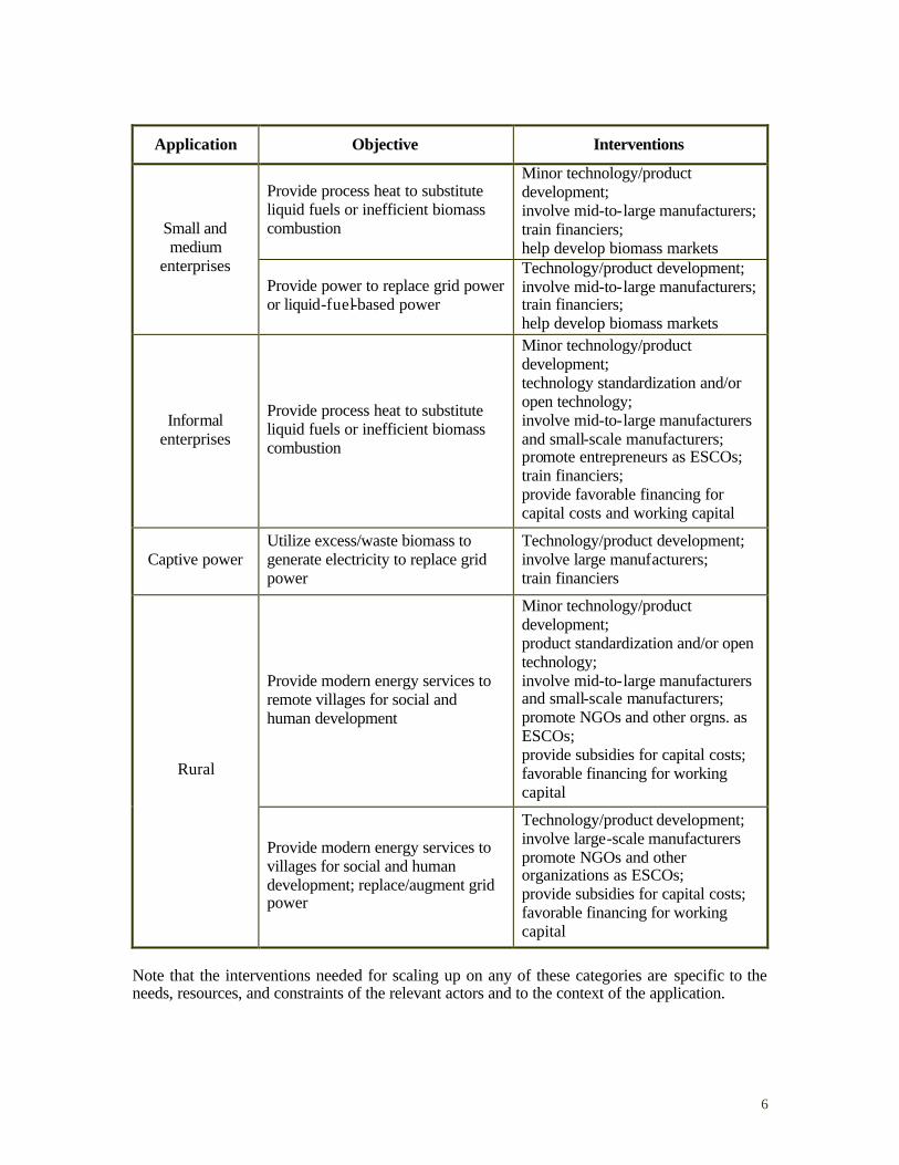
Application Objective Interventions
Provide process heat to substitute liquid fuels or inefficient biomass combustion
Minor technology/product development; involve mid-to-large manufacturers; train financiers; help develop biomass markets
Small and medium
enterprises Provide power to replace grid power or liquid-fuel-based power
Technology/product development; involve mid-to-large manufacturers; train financiers; help develop biomass markets
Informal enterprises
Provide process heat to substitute liquid fuels or inefficient biomass combustion
Minor technology/product development; technology standardization and/or open technology; involve mid-to-large manufacturers and small-scale manufacturers; promote entrepreneurs as ESCOs; train financiers; provide favorable financing for capital costs and working capital
Captive power Utilize excess/waste biomass to generate electricity to replace grid power
Technology/product development; involve large manufacturers; train financiers
Provide modern energy services to remote villages for social and human development
Minor technology/product development; product standardization and/or open technology; involve mid-to-large manufacturers and small-scale manufacturers; promote NGOs and other orgns. as ESCOs; provide subsidies for capital costs; favorable financing for working capital
Rural
Provide modern energy services to villages for social and human development; replace/augment grid power
Technology/product development; involve large-scale manufacturers promote NGOs and other organizations as ESCOs; provide subsidies for capital costs; favorable financing for working capital
Note that the interventions needed for scaling up on any of these categories are specific to the needs, resources, and constraints of the relevant actors and to the context of the application.
7
In addition, some ‘systems’-level interventions (such as setting up an information and awareness program, performance testing facilities, strengthening actor interactions and networks, coordinating and an effort for systematic learning from field experiences) will also be required. Mechanisms for continuous feedback and learning from field experiences are also critical Keeping all of this in mind, perhaps the most fruitful scale -up strategy would be one that initially focuses on pure thermal productive applications. These could be taken up in the short-term, given their economic and financial feasibility and only minor needs for technology development. At the same time, a sequenced approach could be followed for power generation applications. Here, selected pilot transactions could be initiated with a view to promoting appropriate technology and product development and also provide learning about how to best incorporate such efforts into existing institutional structures for electricity provision. As successful products and institutional delivery models emerge, scale -up would follow for such applications.
8
1. B IOMASS GASIFICATION FOR RURAL DEVELOPMENT
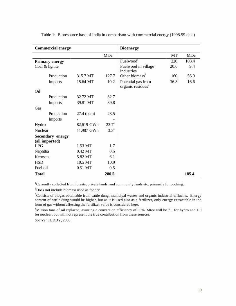
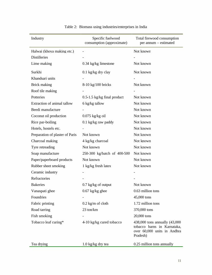
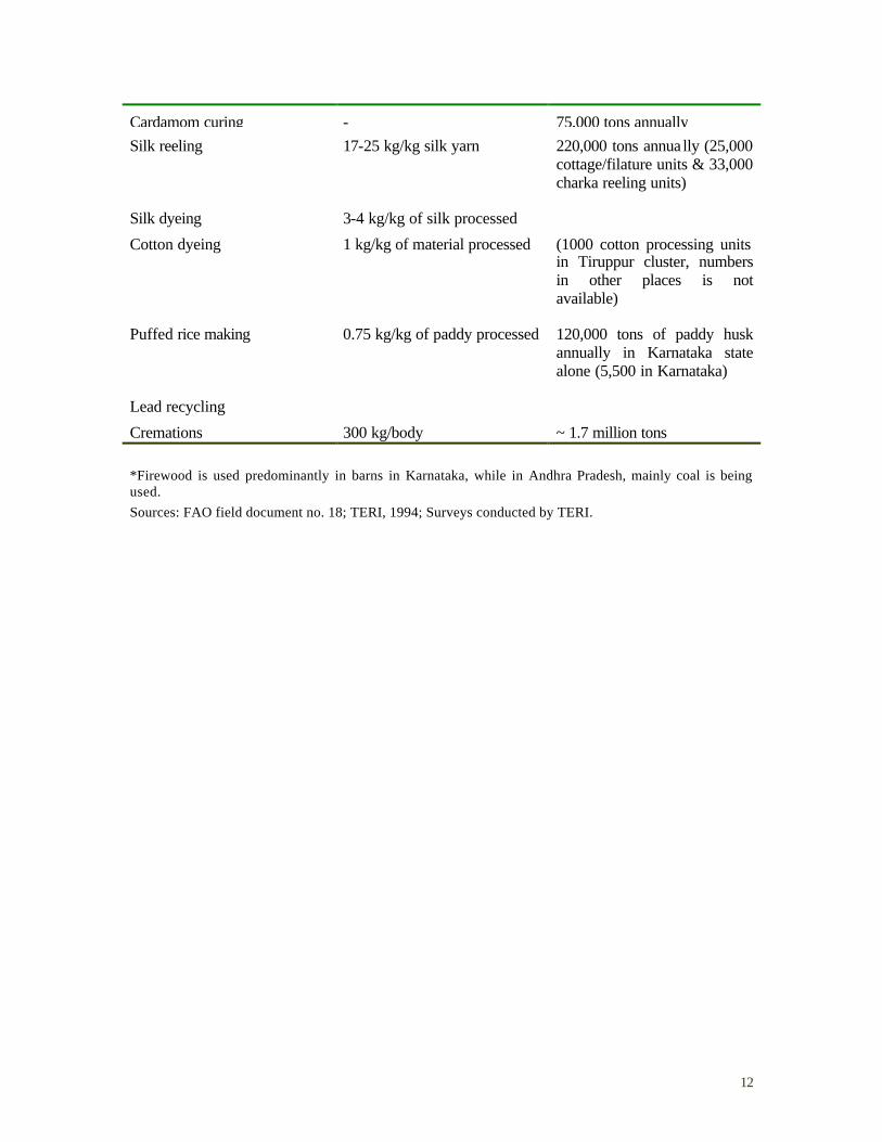
Biomass energy sources currently contribute about 11% of the global primary energy supply (Goldemberg, 2000). Their role in developing country energy supplies is particularly important – for example, in the Indian case, it is estimated that such sources account for about 34 to 41% of the country’s primary energy supply (Reddy, 2000.). The large size of the biomass resource base – comparable in magnitude to other fossil fuel resources such as coal (see Table 1, for example) – and its renewable nature will likely ensure a continuing place of prominence in the future energy supplies, especially as climate change concerns become more pressing. Most biomass utilization, however, in developing countries occurs with a low end-use efficiency. For example, traditional cooking stoves in rural areas have an energy efficiency of about 10% (Smith, 2002). While no systematic studies have been undertaken to measure end-use efficiencies of energy use in small, unorganized industries (or even formal small and medium enterprises (SMEs)), available data for some categories of industries in India indicates efficiencies comparable to those in traditional stoves (Sarvekshana, 1995) (see Table 2). The number of such enterprises is enormous (see Table 3) and hence the total scale of inefficient biomass use, and the resulting environmental, economic, social, and health consequences, is a cause of great concern.1 Furthermore, there remain many areas in most developing countries that are in urgent need of access to modern energy services – such energy services contribute directly to human development by helping provide basic amenities such as lighting and water (Reddy, et. al., 1997). They can also contribute to economic and social development by opening possibilities for a range of productive applications such as micro-enterprises, cold storage, irrigation, etc. Delivering modern energy services to such areas while utilizing local biomass resources would be a highly desirable solution to this rural energy problem. Modern biomass energy conversion technologies like gasification allow for substantial improvements in overall energy efficiency besides offering flexibility of use and significant environmental and health benefits (Johansson, et. al., 2002). The biomass gasification process yields producer gas, an energy carrier that can be burnt relatively easily and can therefore be exploited for generation of electrical power and process heat. Hence the gasification route offers a direct approach to utilize biomass in a manner that helps meet not only basic needs such as lighting and water, but also underpins a range of productive applications that provide livelihoods. This route can help in achieving end-use efficiencies of about 35-40% for heat utilization compared to about 10% for traditional devices (Kartha & Larson, 2000). Furthermore, realizing such levels of efficiencies on the ground can save wood, which is equivalent to fresh afforestation (one ton of firewood is approximately equivalent to one average tree). Conversely, the biomass ‘released’ through such efficiency-improving technologies can be used to provide additional energy services. Hence, if suitably used, biomass gasifiers can play a substantial positive role in improving human development in developing countries, especially in rural areas, while utilizing local resources in an efficient and environmentally friendly manner. As a consequence, over the last two decades, there have been efforts in many countries to explore the implementation of gasifiers in a number of applications and contexts. There has been considerable research on, and evolution, in gasifier designs with a concomitant increase in the ability to utilize a greater range of biomass feedstocks. There have been a number of demonstration and implementation efforts that have begun to yield a wealth of experience that in turn are leading to a refinement of the thinking on how to make further progress on this front. 1 Recent data also suggests that products of incomplete combustion (PICs) that result from inefficient combustion of biomass can have significant greenhouse gas potential (Smith et al., 2000).
9
Ultimately, though perhaps the most important aspect of any contemplation of efforts to realize the potential role of biomass gasifiers in contributing to development in any meaningful manner is the “scale” issue. To put it simply, this technology will make any significant contribution to the enormous energy problem in developing countries only through large-scale deployment. Only if the dissemination and use of gasifiers can be scaled up, can they be considered to be successful contributors to economic and social development in developing countries. This has not happened so far for a variety of reasons. This report aims to highlight the various applications and contexts in which biomass gasification may be successfully utilized at a large scale. It also discusses the various dimensions that need to be considered in scaling up deployment in any of these categories, and suggests possible approaches that might be particularly promising. The analysis in this report builds on the experience and lessons from the substantial efforts in India on biomass gasifier development and dissemination over the last two decades. It also explicitly takes a systems perspective in analyzing the Indian case as well as possible ways forward in order to mainstream gasifier use in developing countries.
10
Table 1: Bioresource base of India in comparison with commercial energy (1998-99 data)
Commercial energy Bioenergy
Mtoe MT Mtoe Primary energy Fuelwood1 220 103.4 Coal & lignite Fuelwood in village
industries 20.0 9.4
Production 315.7 MT 127.7 Other biomass2 160 56.0 Imports 15.64 MT 10.2 Potential gas from
organic residues3 36.8 16.6
Oil Production 32.72 MT 32.7 Imports 39.81 MT 39.8 Gas Production 27.4 (bcm) 23.5 Imports - - Hydro 82,619 GWh 23.74 Nuclear 11,987 GWh 3.34 Secondary energy (all imported)
LPG 1.53 MT 1.7 Naphtha 0.42 MT 0.5 Kerosene 5.82 MT 6.1 HSD 10.5 MT 10.9 Fuel oil 0.51 MT 0.5 Total 280.5 185.4
1Currently collected from forests, private lands, and community lands etc. primarily for cooking. 2Does not include biomass used as fodder 3Consists of biogas obtainable from cattle dung, municipal wastes and organic industrial effluents. Energy content of cattle dung would be higher, but as it is used also as a fertilizer, only energy extractable in the form of gas without affecting the fertilizer value is considered here. 4Million tons of oil replaced, assuring a conversion efficiency of 30%. Mtoe will be 7.1 for hydro and 1.0 for nuclear, but will not represent the true contribution from these sources.
Source: TEDDY, 2000.
11
Table 2: Biomass using industries/enterprises in India
Industry Specific fuelwood consumption (approximate)
Total firewood consumption per annum – estimated
Halwai (khoya making etc.) - Not known
Distilleries - -
Lime making 0.34 kg/kg limestone Not known
Surkhi 0.1 kg/kg dry clay Not known
Khandsari units - -
Brick making 8-10 kg/100 bricks Not known
Roof tile making - -
Potteries 0.5-1.5 kg/kg final product Not known
Extraction of animal tallow 6 kg/kg tallow Not known
Beedi manufacture - Not known
Coconut oil production 0.075 kg/kg oil Not known
Rice par-boiling 0.1 kg/kg raw paddy Not known
Hotels, hostels etc. - Not known
Preparation of plaster of Paris Not known Not known
Charcoal making 4 kg/kg charcoal Not known
Tyre retreading Not known Not known
Soap manufacture 250-300 kg/batch of 400-500 Not known
Paper/paperboard products Not known Not known
Rubber sheet smoking 1 kg/kg fresh latex Not known
Ceramic industry - -
Refractories - -
Bakeries 0.7 kg/kg of output Not known
Vanaspati ghee 0.67 kg/kg ghee 0.63 million tons
Foundries - 45,000 tons
Fabric printing 0.2 kg/m of cloth 1.72 million tons
Road tarring 23 ton/km 370,000 tons
Fish smoking - 20,000 tons
Tobacco leaf curing* 4-10 kg/kg cured tobacco 438,000 tons annually (43,000 tobacco barns in Karnataka, over 60,000 units in Andhra Pradesh)
Tea drying 1.0 kg/kg dry tea 0.25 million tons annually
12
Cardamom curing - 75,000 tons annually Silk reeling 17-25 kg/kg silk yarn 220,000 tons annua lly (25,000
cottage/filature units & 33,000 charka reeling units)
Silk dyeing 3-4 kg/kg of silk processed
Cotton dyeing 1 kg/kg of material processed (1000 cotton processing units in Tiruppur cluster, numbers in other places is not available)
Puffed rice making 0.75 kg/kg of paddy processed 120,000 tons of paddy husk annually in Karnataka state alone (5,500 in Karnataka)
Lead recycling
Cremations 300 kg/body ~ 1.7 million tons *Firewood is used predominantly in barns in Karnataka, while in Andhra Pradesh, mainly coal is being used. Sources: FAO field document no. 18; TERI, 1994; Surveys conducted by TERI.

13
Table 3: Summary of unorganized enterprises in India for reference years 1990 and 1995
1990 1995
Number of enterprises (millions) 15.35 14.5
Per enterprises expenses on fuel (Rs./year) 876 629
Per enterprise expense on electricity (Rs./year) 845 3566
Per enterprise expenses on fuel and electricity (Rs./year) 1721 5195
Per enterprise expenses on inputs (Rs./year) 40460 94208
Enterprise located in rural areas (%) 75.83 72.37
Enterprise located in urban areas (%) 24.17 27.63
Enterprise that do not consume energy (millions) 10.29 NA
Number of enterprises consuming energy (millions) 5.06 NA
Number of enterprises consuming firewood (millions) 1.40 NA
Number of enterprises consuming charcoal (millions) 0.42 NA
Number of enterprises consuming biomass fuels (millions) 1.82 NA
Note: Rs. 48 ~ US $1
Source: 45th and 51st rounds of survey of unorganized manufacturing sector (Sarvekshana, 1995)

14
2. DEVELOPMENT AND DISSEMINATION OF BIOMASS GASIFIERS IN INDIA2
The development and dissemination of modern biomass gasifiers in India began in the early 1980s. During this period, a number of research institutions commenced efforts to examine different aspects of biomass gasifier use as well as to develop indigenous gasifiers and gasifier-based energy systems (GESs). Much of the initial work centered on small wood-based gasifiers that would be useful for applications such as powering irrigation pumpsets. This focus was motivated by the thinking within the Department of Non-conventional Energy Sources (DNES) that it would be beneficial to utilize renewable energy sources to provide power for irrigation pumping3 – even at that time, India had about half a million diesel pumpsets for irrigation. The earliest of these efforts began with some work by a French couple, Vincent and Marie -Sabine D’Amour at the Jyoti Solar Energy Research Institute (JSERI) in Gujarat. JSERI had been established by Jyoti Ltd., an industrial house, to develop renewable energy technologies. After some experimentation, JSERI researchers developed a 5-horsepower (hp) gasifier that was suitable for coupling to a diesel engine that in turn could power irrigation pumpsets. The design and drawings for this design belonged to Jyoti Ltd., and the firm, through its energy division, started manufacturing these gasifiers. (In 1984, JSERI became an autonomous, not-for-profit organization that was funded in part by the government. It also changed its name to the Sardar Patel Renewable Energy Research Institute (SPRERI).) Dr. B.C. Jain who headed the energy division at Jyoti left in 1986 to start his own firm, Ankur Scientific Energy Technologies, Ltd., to focus on the development, manufacture, and popularization of biomass gasifiers and solar hot water systems. A number of other institutions also started work on gasifiers in the early 1980s. The effort on biomass gasifiers at the Indian Institute of Science, Bangalore (IISc) was init iated in 1981 by Dr. H.S. Mukunda and Dr. U. Shrinivasa with financial support from the Karnataka State Council for Science and Technology. The research was catalyzed by the work done at the Solar Energy Research Institute (SERI) in the U.S., and the init ial focus was to study and modify the SERI design for a 5 hp gasifier for coupling with an internal combustion engine for power generation. Researchers from the Tata Energy Research Institute (TERI) were first trained on gasifiers at JSERI in 1982. Eventually, researchers at TERI’s Field Research Unit, then at Pondicherry, constructed a 5 hp gasifier by 1984. This effort was funded by TERI, with the institute providing the hardware components as well as manpower. A group at the Indian Institute of Technology (IIT)-Bombay led by Dr. P.P. Parikh began initially with a collection and review of the gasification literature. Later, realizing the need for appropriate testing facilities to support the nascent gasifier efforts in the country, the IIT-Bombay group also set up a testing laboratory with DNES funding. Work on biomass characterization was initiated at IIT-Delhi. Other institutes such as Punjab Agricultural University, Ludhiana, and Nimbkar Agricultural Research Institute, Phaltan, also started work on biomass gasification. In addition to supporting research and testing, DNES was also organizing R&D meetings that brought together the small number of senior researchers on this topic. All of these activities served as the backdrop for the first major initiative under the Biomass Gasifiers Programme
2 Unless otherwise mentioned, information in this chapter is derived from authors’ own knowledge and experiences, interviews with researchers, practitioners and policy-makers (see Annexure 4), internal documents and in-house publications of organizations, and web-based information. 3 Some attempts to develop solar-thermal-powered pumpsets were already under way.
15
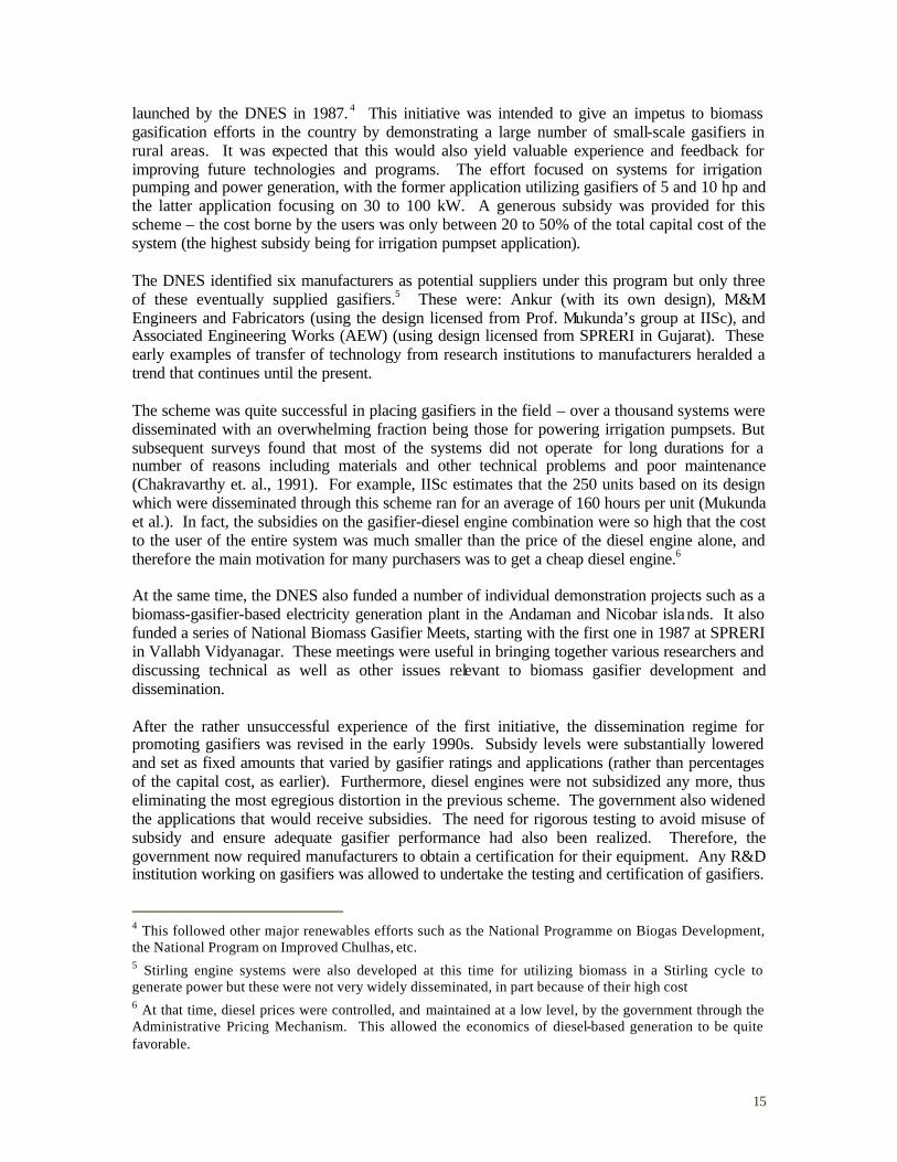
launched by the DNES in 1987. 4 This initiative was intended to give an impetus to biomass gasification efforts in the country by demonstrating a large number of small-scale gasifiers in rural areas. It was expected that this would also yield valuable experience and feedback for improving future technologies and programs. The effort focused on systems for irrigation pumping and power generation, with the former application utilizing gasifiers of 5 and 10 hp and the latter application focusing on 30 to 100 kW. A generous subsidy was provided for this scheme – the cost borne by the users was only between 20 to 50% of the total capital cost of the system (the highest subsidy being for irrigation pumpset application). The DNES identified six manufacturers as potential suppliers under this program but only three of these eventually supplied gasifiers.5 These were: Ankur (with its own design), M&M Engineers and Fabricators (using the design licensed from Prof. Mukunda’s group at IISc), and Associated Engineering Works (AEW) (using design licensed from SPRERI in Gujarat). These early examples of transfer of technology from research institutions to manufacturers heralded a trend that continues until the present. The scheme was quite successful in placing gasifiers in the field – over a thousand systems were disseminated with an overwhelming fraction being those for powering irrigation pumpsets. But subsequent surveys found that most of the systems did not operate for long durations for a number of reasons including materials and other technical problems and poor maintenance (Chakravarthy et. al., 1991). For example, IISc estimates that the 250 units based on its design which were disseminated through this scheme ran for an average of 160 hours per unit (Mukunda et al.). In fact, the subsidies on the gasifier-diesel engine combination were so high that the cost to the user of the entire system was much smaller than the price of the diesel engine alone, and therefore the main motivation for many purchasers was to get a cheap diesel engine.6 At the same time, the DNES also funded a number of individual demonstration projects such as a biomass-gasifier-based electricity generation plant in the Andaman and Nicobar islands. It also funded a series of National Biomass Gasifier Meets, starting with the first one in 1987 at SPRERI in Vallabh Vidyanagar. These meetings were useful in bringing together various researchers and discussing technical as well as other issues relevant to biomass gasifier development and dissemination. After the rather unsuccessful experience of the first initiative, the dissemination regime for promoting gasifiers was revised in the early 1990s. Subsidy levels were substantially lowered and set as fixed amounts that varied by gasifier ratings and applications (rather than percentages of the capital cost, as earlier). Furthermore, diesel engines were not subsidized any more, thus eliminating the most egregious distortion in the previous scheme. The government also widened the applications that would receive subsidies. The need for rigorous testing to avoid misuse of subsidy and ensure adequate gasifier performance had also been realized. Therefore, the government now required manufacturers to obtain a certification for their equipment. Any R&D institution working on gasifiers was allowed to undertake the testing and certification of gasifiers.
4 This followed other major renewables efforts such as the National Programme on Biogas Development, the National Program on Improved Chulhas, etc. 5 Stirling engine systems were also developed at this time for utilizing biomass in a Stirling cycle to generate power but these were not very widely disseminated, in part because of their high cost 6 At that time, diesel prices were controlled, and maintained at a low level, by the government through the Administrative Pricing Mechanism. This allowed the economics of diesel-based generation to be quite favorable.
16
At the same time, the commercial feasibility of gasifiers for thermal applications was also being demonstrated. The combination of the modified subsidy program and the emergence of commercial opportunities provided a boost to gasifier development and deployment in India. As a result, there has been substantial activity in a number of research institutions aimed at various scientific and technical aspects of gasifier design. This includes efforts directed at:
• utilizing various kinds of biomass in gasifiers such as rice husk, sugarcane waste, and mustard stalks. There were also efforts to use biomass in powdery and briquetted form to improve the feasibility of gasifying a range of feedstocks.
• developing and incorporating technical improvements to improve performance, robustness, as well as lifetimes of gasifiers.
• meeting different thermal productive applications such as drying of agricultural products (cardamom, tea, rubber, marigold, etc.), brick processing, silk reeling, textile dyeing, chemicals processing and institutional cooking. (Kishore et. al., 2001)
• enhancing gasifier-based electrical generation. This required improving the quality of gas being produced (especially in terms of particulate and tar content). It also required modifying diesel engines and developing control systems to improve the effectiveness of coupling these engines and gasif iers. There were also some efforts at modifying gasifiers and engines so as to have 100%-producer-gas-based power generation systems (as opposed to the traditional duel-fuel operation).
• scaling-up gasifiers to large sizes for both thermal and electrical applications. Gasifiers up to 500 kW for electrical applications, and equivalent sizes for thermal applications, are now available.
The institutional landscape has also evolved somewhat over the years. While the major R&D institutions that had begun work on gasifiers in the early 1980s continue to be active in the area, only a few other R&D actors have emerged subsequently, and only with the help of government support. There are, though, now a large number of gasifier manufacturers in the country.7 These can generally be classified into two categories: those that license technology from research institutions and those that have developed their own technologies. Notably, most of these manufacturers operate at a small scale, selling about 10-20 gasifiers a year. Ankur, the largest of the Indian gasifier manufacturers, has installed since its inception (or is in the process of installing) gasifiers totaling about 20 MW of electrical and thermal-equivalent capacity.8 (See Annex 3 for a detailed description of the activities of some of the major gasifier development and/or deployment institutions.) The Ministry of non-Conventional Energy Sources (MNES, the successor to DNES) remains the main funder of gasifier R&D in the country and deployment through its subsidy program. Until recently, it also supported activities at the various institutions designated as the gasifier action research programs (GARPs). But a number of other actors have also started playing a role in funding and catalyzing gasifier-related activities in the country. On the public -sector side, these include state nodal agencies such as the Renewable Energy Development Agencies of West
7 These include: Ankur (Baroda), AEW (Tanuku, AP), Chanderpur Works (Haryana), Cosmo (Raipur), Figu Engineering Works (Gangtok), Grain Processing Industries (Calcutta), Netpro (Bangalore), Paramount Enviro-energy (Kottayam), Radhe Industries (Rajkot), Silktex (Bangalore), Vijay Engineering (Bangalore), 3M Industries (Mumbai). (Source: MNES, 2001 and authors’ knowledge) 8 Based on interviews with personnel at Ankur (see Annexure 4).
17
Bengal (WBREDA), Gujarat (GEDA) and Orissa (OREDA). Some donor agencies have also supported specific gasifier development and dissemination activities – for example, the Swiss Agency for Development and Cooperation (SDC) has provided support for the development of gasifiers for silk reeling and cardamon drying enterprises. DESI Power has been supported, among others, by the Shell Foundation, FREND (a Swiss Foundation), and the Government of the Netherlands. By now, gasifiers have found utility in a range of industries and applications (see Table 4) across the country through numerous demonstration projects and commercialization activities. Over 1800 gasifiers have been installed under the MNES subsidy programs (MNES, 2002), and an estimated 400 additional gasifiers have been installed outside the subsidy regime9. (Annex 4 describes a number of case studies of gasifier implementation.) There has also been the emergence of several small-scale entrepreneurs who are trying to manufacture and/or install gasifiers on a purely commercial basis (since only the manufacturers that have received certification are eligible for subsidies). Partly as a result of this situation, there is a large variation in performance of systems, capital costs, and maintenance requirements. In fact, it is likely that many of the claims of gasifier manufacturers/installers may not stand the scrutiny of a rigorous field evaluation but there is a complete lack of systematic data-gathering about experiences with, and performance of, installed systems. And despite the significant experience with gasifiers in the country, there really has been no significant scale -up in their deployment. What is it that explains the evolution and structural features of this landscape? The significant progress in gasifier technologies and the concomitant augmentation of the installed base across various applications result from the long-term involvement and commitment of key technical personnel and institutions in gasifier development and deployment. This has also required long-term and consistent support from the MNES. The fact that research institutions have been also involved in product development and dissemination has been helpful in the improvement of the technologies. But in many cases, this may also impede appropriate product10 design and development since these activities are not necessarily their core competence. Furthermore, while there are a number of actors in the area, interactions between them are only limited – for example, collaborations between R&D institutions are almost non-existent, and only in a few cases are there relationships between manufacturers and R&D institutions. The lack of efforts to learn systematically from field experiences has constrained the ability to improve gasifier-based systems and make them more robust. This, coupled with the absence of dissemination of information and awareness about gasifier utilization and performance in various applications, as well as the lack of development of technical standards for gasifiers, has led to lack of user confidence in these systems and hampered their dissemination. While the government has been instrumental in the development and dissemination of gasifier technology in the country, it does not have policies specifically designed to promote large-scale deployment. While its programs have been successful at adding to the installed gasifier capacity in the country, this has happened by simple replication of demonstration or small-scale activities rather than by the emergence of different modes of industrial organization (for example, mass production by a few manufacturers instead of craft production by many small manufacturers) required to move from small-scale to large-scale deployment. The lack of efforts to experiment
9 Based on authors’ own knowledge. 10 We differentiate here between ‘technology’ and ‘products.’ The ‘technology’ is the basic design of the gasifier while the ‘product’ is the manufactured gasifier and the other components that together constitute the system that delivers the required energy services to the user (Sagar and Mathur 2001).

18
with, and promote, innovative institutional models to overcome existing barriers to deployment in particular applications has also constrained the uptake of gasifiers.

19
3. B ARRIERS FOR SCALING-UP11
This chapter presents and discusses some of the main categories of barriers that seem to have hindered biomass gasifier deployment in the Indian context. It should be noted that this is not a comprehensive list but rather one that touches upon particularly important issues. Many of these barriers will also be relevant in other developing countries.
3.1 Technology/product development and production
Feedstock utilization Gasification technology to utilize a variety of agricultural wastes (such as mustard stalk, groundnut shells, and corncobs) is still not available, although there are ongoing efforts for utilizing a number of feedstocks. Even in cases where gasifier technology has been deployed, there may still remain some questions about field performance – for example, our interviews with stakeholder indicated some concerns about rice-husk-based gasifiers. Development of feedstock processing techniques such as briquetting and pelletisation will enable a variety of agro-residue utilization but these face technical and economic barriers at present.12 Downscaling of gasifiers sizes While there has been a major effort over the past two decades to develop large gasifier sizes that can take advantage of economies of scale in energy service delivery, there remains a need for small gasifiers that can be utilized in applications where the loads are smaller, particularly in rural areas and in informal enterprises. Gas cleaning/cooling This is of concern for power applications. Large gasifier units (beyond 100 kW) are generally linked to turbo-charged/after cooled diesel engines. The turbocharger requires very high quality producer gas and there are significant concerns about present gas quality not being compatible for such applications. Engine development Technical barriers exist in conversion and modifications of diesel engines to 100% producer gas mode, especially more so because of the reluctance of engine suppliers to collaborate with gasifier manufacturers in these developmental efforts. The former perceive high technical risks and therefore do not provide performance warranties for engines coupled to gasifiers. Natural gas engine modifications to run on producer gas involve high costs and large capacity derating that effectively raises costs. Besides, natural gas engines are not readily available, especially in small capacities, as there are only a few suppliers. System automation Process control and automation in gasifier systems (with respect to feedstock processing and feed charging, change over from diesel only to dual-fuel mode, etc.) has not been adequately developed. While there are cost barriers to the development of such technologies, they would be
11 Information in this chapter is primarily based on interviews with researchers, practitioners and policy-makers (see Annexure 4). 12 For briquetting, there are uncertainties with respect to behavior of briquettes under high temperature and high wear and tear of machines that result in high replacement costs. Alternate processing techniques such as pelletisation are emerging but there are further development needs.
20
extremely useful in applications where the personnel costs contribute significantly to the operating expenses. Such systems would be more appropriate in industrial applications where skilled personnel are available rather than in rural/remote area applications. Manufacturing capabilities Despite the production and dissemination of a substantial number of gasifiers, manufacturing capabilities in this area remain very limited. Many of the gasifier manufacturers are mainly small workshops or fabricators that produce gasifiers in a manner akin to craft production. Thus the increase in the gasifier installed capacity has come about mostly through replication of the small-manufacturing model rather than a shift to mass production techniques within large engineering firms that can then take advantage of economies of scale as well as learning from production. 3.2 Information and awareness
Technology/product selection In the present Indian situation, information on product specifications (technical specifications, performance parameters, O&M procedures) as well as prices offered by different technology suppliers is not available in public domain – this impedes competitive and fair selection of technology suppliers by users. May actors also express a concern for technology selection often being driven not by technology competitiveness but rather by informal alliances between manufacturers and project promoters. Technology/product operation Information with respect to feedstock specifications and characteristics as well as the variety of feedstock compatible with gasifier design is often not available to the user from the technology supplier – this adversely impacts system performance. For example, the user is often only aware of the moisture content control in the feedstock, but unaware of other specifications such as the wood characteristics (e.g., presence of bark) that influence operation. Users also encounter problems in feedstock processing (due to rigid specifications by some technology suppliers) and feed charging operations (cases of manual charging). O&M difficulties also arise in gas cleaning/cooling components (problems in manual recycling of the sand filter). Often, users do not have sufficient technical knowledge and information on the technology and often place demands on the system incompatible with design and operating procedures. Problems also arise due to users not being adequately trained to handle system operation and maintenance procedures that often lead to over-dependence on the technical back-up13 unit for undertaking these activities. There are also no performance benchmarks or compilation of best operating procedures and practices. Operating manuals are often incomprehensible to users as they are written in English instead of in local languages. Difficulties also arise in judging system performance, as there is little emphasis on measurement and record keeping of performance parameters. In the absence of systematic methods for performance measurement and verification, there exist gaps between performance claims by manufacturers and those perceived by the user – this adversely affects user confidence. Application scope and benefits Information dissemination efforts targeted at key stakeholders to educate them about the scope of applications of gasifiers have been rather limited. Even though experiences show that thermal
13 The technical back-up unit (TBU) is usually the technology supplier or the state nodal agency. In some cases it may be the R&D institute.
21
productive uses of gasifiers in industries are commercially attractive, there have been only a few systematic efforts to target segments of potential beneficiaries in this area through information dissemination and awareness programs. Users may also perceive uncertainties in technological performance and potential adverse impact on product quality by a switch to gasifiers.14 Though some experiences show that user willingness for gasifier installation is linked to auxiliary benefits (especially relevant in the context of gasifier applications in industries) such as impact on plant productivity and product quality, the technology supplier often does not have this information available to convince the user. Prospective users are also often unaware of overall potential benefits. Information and awareness on biomass-based technologies among intermediary stakeholders such as NGOs, industry groups, and micro-finance institutions is also limited. The awareness level among policy makers is also perceived to be low, which at times lead to greater emphasis on other renewable technologies such as solar photovoltaics and wind. 3.3 Experimentation and learning
Experimentation with delivery models Since the dissemination of gasifiers has been dominated by a few major actors, the general trend has been towards replication of specific models followed by these actors. This has included deployment of gasifiers for power and thermal applications in small and medium enterprises (SMEs) taking advantage of government subsidies, for rural electrification in government-sponsored demonstration projects, as well as for applications in informal enterprises and SMEs on a purely commercial basis. There have been some efforts to experiment with energy service company (ESCO)-like delivery models and with cluster-based approaches but these have been few and far between, and have not been undertaken on any systematic basis so as to build the foundation for selecting among, improving upon, and disseminating these delivery models. Learning from experiences Performance of systems operating in field are rarely reviewed and monitored – in fact, there are no institutional arrangements in place for independent monitoring and evaluation of gasifier performances in field. 15 There is a low level of feedback from prior projects due to near-absence of relevant project experience documentation. There are no systematic methods for highlighting lessons from different experiences, and sharing of knowledge and experiences through modes such as case studies and discussions. Even for demonstration projects, there are no methods for information dissemination on successes and failures. There are no institutional mechanisms for bringing stakeholders to a common forum for sharing of experiences. Learning from successful experimentations in market development strategies, which often have involved considerable efforts by technology supplier to convince user and getting the first customer, are rarely disseminated to facilitate future efforts. Similarly, experience suggests that providing a secure fuel supply to the user along with technology supply has been a successful dissemination strategy, but such practices are not being replicated.
14 An example is the case of gasifier installation in a steel re-rolling mill – the mill owner perceived that the furnace temperature after gasifier installation would not be sufficient for his operations and affect product quality. Systematic trials and measurements were needed to convince the user. 15 It is not even known how many of the gasifiers installed in the country remain functional. A survey of gasifiers in a particular state indicates that very few installed systems were functional (Chakravarthy, 1991).
22
3.4 Actor linkages and interaction
Biomass supply The non-existence of a reliable and sustainable biomass supply chain restricts deployment and dissemination. There are no reliable fuel supply, transportation and distribution linkages – for example, biomass fuel supply depots do not exist. In the absence of established coordination among different actors in the biomass supply chain, gasifier users have to develop their own supply linkages that adds to the transaction costs of switching over to this technology. Technology/product innovation There are no institutional mechanisms for interactions and networking among different stakeholders – while some government-initiated efforts existed under GARP, with its dissolution, no forum exists for interactions. There are isolated cases of initiatives being undertaken by certain stakeholders such as state nodal agencies, but no nationwide efforts exist. The R&D efforts of different institutions have been fragmented, without adequate sharing of knowledge and experiences across the institutes. There are also no systematic linkages between R&D activities and field applications – hence there are no institutionalized processes for feedback from field to R&D and vice versa. There are barriers to interactions among key stakeholders such as gasifier manufacturers and engine suppliers – gasifier manufacturers are often unwilling to share performance-related information with engine suppliers. Participation is also hindered by high-risk perceptions of engine suppliers. No mechanisms also exist for interactions between technology suppliers and users, nor is there any forum for interactions among users. While there are some interactions between policy-makers and selected research institutions and manufacturers, there are almost none between policy-makers and users. 3.5 Economic and financing issues
System costs High system costs are driven by high capital costs and high costs of transportation in supplying the technology from manufacturing to user site 16. Difficulties in capital access for users hinder adoption. There are concerns on economic viability of dual-fuel based operations, especially in the context of government dismantling of the administrative pricing mechanism for petroleum products in the country. The economic viability for power applications may improve with a shift from dual-fuel to 100%-producer-gas-based systems but there are high costs associated with development of these systems related to engine redesign and modification, and derating in engine capacities that effectively increases costs. In the context of power applications in rural areas, there are adverse impacts on plant economics by low-load patterns especially in the initial stages of a project when load levels are low. There are tradeoffs between costs and performance improvements in incorporating system automation and instrumentation – an increase in system costs due to automation make them unaffordable to certain user categories (such as remote/rural power applications), but may be more relevant for industrial applications. But such options have not been systematically explored.
16 Very often there is a single manufacturing site for a technology supplier, while the users may be dispersed nationwide.
23
Fuel costs As a biomass supply market is non-existent, there are wide fluctuations in prices of biomass fuel (e.g., price of rice husk can vary between 400 rupees per ton to 1200 rupees per ton)17. This poses a high risk in setting up projects without reliable supply linkages. Furthermore, the long-term implications of large-scale gasifier projects on local biomass prices is not well-studied. Full-cost pricing Economic assessment of alternate energy supply options (conventional and non-conventional sources) in evaluating technology choices rarely adopt full-cost pricing techniques in terms of fuel costs, pricing of equipment, setting up of T&D networks, etc. Costs related to socio-environmental externalities are not internalized in assessing competitiveness among alternate technology choices for delivering energy service – this restricts gasifier technology deployment. Financing risk perceptions and transaction costs Financial institutions often perceive high risks – technological and financial – for biomass gasification projects. The former is related to uncertainties in gasifier and/or system performance while the latter is related to uncertainties in the recovery of user charges in the absence of mechanisms for securing recovery from users. For financing gasifier projects, especially for SMEs or informal enterprises, the loan amounts needed by individual users are small – this renders transaction costs disproportionately high. Thus public financial institutions existing in the country for financing of renewable energy projects such as the Indian Renewable Energy Development Agency (IREDA) provides loans only to projects requiring large investments. There is a lack of initiatives in developing innovative micro-financing mechanisms. For example, options for setting up lending mechanisms to a number of small-scale units forming a cluster with large aggregate capacity have not been adequately explored. Due to a dearth in resource availability in the sector, some institutions are over-dependent on grants that may not be sufficient for attracting qualified, dedicated personnel for undertaking project development. Financing options from sources such as rural co-operative banks in provid ing soft loans to entrepreneurs have also not been well-explored. There also remain structural difficulties in delivery of finances. For example, captive power plants such as rice mills may be potentially attractive for loan provision by IREDA. But most of these rice mills are proprietorships and IREDA is forbidden to provide loans to such entities. Innovative financing mechanisms based on setting up of an ESCO with sharing of accrued savings between the ESCO and the beneficiary have not evolved (as has happened in some other renewable energy applications such as solar water heating systems). Application-oriented financing packages The financing of gasifier applications has overly relied on government subsidies and there have been little attempts to design financing packages suited towards different end-use application categories. Even commercially viable applications, such as gasifier use for productive applications in industries, continue to draw on government subsidies. Different financing mechanisms have not evolved for ‘socially-oriented’ projects (such as the ones for rural/remote area electrification) that have a stronger case for public support vis-à-vis commercial projects (such as the ones for thermal productive uses or captive power generation in industries).
17 Based on personal communication with IREDA official.
24
3.5 Policy issues
Gasifier dissemination policy orientation While the government program has relied mainly on subsidies and an orientation towards target fulfillment, it has had little emphasis on performance. Furthermore, the implementation of the government effort has not been driven by need assessment and performance evaluation. In fact, there has been little emphasis on systematic review of the program. There are also distortions in subsidy policies in terms of the structure and nature of subsidies. Some of these arise due to subsidies being applicable even for commercially viable applications of gasifiers such as productive uses in industries and region-wise (higher subsidy to locations in the north-eastern regions) and category-wise (higher level of subsidy offered to consumer categories belonging to certain socio-economic classes) classification of subsidies. Frequently changing government policy guidelines with respect to subsidies also results in awareness problems among users. The installations of systems are often driven by subsidy motives and draw little commitment from users. There has been no shift from capital subsidy to performance-based incentives such as soft loans and tax credits. There are also adverse impacts due to uneven support to R&D institutions and sudden withdrawals in government support without alternate support in place. For example, after the dismantling of government support for GARPs, there remains no agency for testing and certification of gasifiers. There are uncertainties with respect to resumption of these activities that adversely affects dissemination. Interface with other policies Policy barriers exist with respect to supply and distribution of electricity. For example, third-party sale of electricity by private power producers is not encouraged. There are non-uniform policies across states with large fluctuations over time18 that pose high financing risks. Due to electricity tariff distortions across different categories of consumers, non-electrif ied villages often choose to wait for grid electricity supply over long periods of time as grid electricity supply price would be very low – this discourages setting up of decentralized power systems. In fact, the general government tendency to provide subsidies to informal enterprises and to the rural sector often acts as a barrier to the adoption of gasifiers where the actors may perceive forthcoming subsidies. Power supply from decentralized sources is not integrated within the reforms framework and finds no explicit mention in the recent policy document such as the Electricity Act 200319. Within the regulatory framework, regulatory interventions related to pricing of energy supply from decentralized sources are not incorporated. Policy guidelines that integrate government’s target to electrify all the unelectrified villages with identification of decentralized supply options to fulfill this target remain limited. 20 Integration of biomass-based energy projects (especially for rural/remote area electrification programs) with overall development policies of the government has not taken place and there is
18 In the states of Andhra Pradesh and Karnataka, for example, wheeling charges were increased steeply within a short period, making several renewable energy projects unprofitable. 19 Ministry of Power, Government of India, website. (http://powermin.nic.in) 20 Some initiatives are being taken under the recently announced Rural Electricity Supply Technology (REST) mission of the Government of India. (http://powermin.nic.in)

25
little coordination of activities with other government departments engaged in rural development programs. Bureaucracy The procedures for government subsidy approval and disbursement are lengthy and cumbersome that deters potential beneficiaries (although to be fair, this is not a particular problem for the renewables areas only). A bottom-up structure exists related to project development and implementation that leads to high cost and time overruns due to factors such as procedural bottlenecks and approval needs from multiple agencies.
26
4. M AINSTREAMING BIOMASS GASIFIERS
The Indian experience has shown the tremendous potential of biomass gasifiers in providing thermal and electrical energy services for a variety of applications in a developing country. But the experience has also revealed the various hurdles on the path to widespread deployment of this technology. Hence efforts to scale up and mainstream the use of biomass gasifiers for providing energy services in developing countries will need to employ a systematic approach to build on past lessons and avoid potential pitfalls. This should include an examination of specific aspects of the technology development and deployment process as it relates to gasifiers. It should also focus on selected applications that seem to show the greatest potential for large-scale gasifier deployment in terms of technical, economic, and financial feasibility as well as social, economic, and environmental benefits. 4.1 Gasifier technology development and deployment
Successful technology dissemination is the outcome of an iterative process that begins with an initial assessment of user needs and resources. Such an assessment needs to underpin the development of the product aimed at satisfying the needs of the consumers. But the process of the product development itself generally involves several revisions as tests on prototypes in the laboratory and in the field yield data about technical and economic performance during operation – such information is valuable in making improvements to the product and evaluating its viability. Often these tests also involve getting feedback from users on the product’s fit with their needs. As the evolution of the product design moves it closer to the manufacturing stage, industrial design issues such as manufacturability and ergonomics also need to be considered, as also do aspects such as appearance that may play a significant role in product marketing. In fact, issues such as pricing, sales strategies, and distribution channels need to be resolved even before any commercial production can commence – all of this is required to ensure delivery to, and uptake by, users. Given the specificity of user needs in many cases, the product may need to be customized in order to deliver the appropriate level of service desired by the consumers. Of course, suitable maintenance plays a critical role in continued satisfactory operation during product use. Valuable lessons and insights about the product design are invariably gained during its use (as well from the manufacturing stage, often) – these, in turn, can assist in the refinement of the product. Figure 1 shows, in a stylized and simplified fashion, this chain of activities. As mentioned earlier, it is imperative to think of this technology development and deployment process not as a linear or sequential set of activities but as a recursive process with close linkages between the different stages. Mainstreaming a technology requires paying attention to each of these elements. In the particular case of gasifier-based energy systems (GESs), some aspects of this process require further discussion. Technology development While much work has been done on the development of gasifier technologies aimed at utilizing a number of biomass feedstocks for different applications, there are still major gaps that remain. There can be classified into three categories:
• A ‘technology’ gap: Despite much progress over the last few decades, there remains a need for developing gasifiers that can successfully and effectively utilize agricultural wastes such as coconut shells. Economical biomass processing technologies could also assist in the utilization of a greater range of feedstocks. The development of small and
27
robust gasifiers is particularly critical for rural and informal enterprise applications. The development of a robust 100% producer gas engine also stands as a barrier to the implementation of gasifiers in electrical power generation in contexts where the use of diesel in not possible or desirable for duel-fuel applications. Improvements in instrumentation and control systems will also greatly assist in better operation and maintenance of GES.
• An ‘assessment’ gap: A number of designs that have been utilized in various demonstration or commercial projects around the world. While there is consensus on some design elements of gasifiers for specific feedstocks and/or applications, there has been no systematic effort at validating the performance claims of the various designs and carrying out a comparative assessment of various gasifier and energy systems’ designs to reach consensus on technical choices which would help in streamline the future design process.
• A ‘design’ gap: While a number of gasifier designs have been developed by different institutions, their manufacture has been mostly in small numbers for scattered applications. This has precluded a unified attempt to design gasifiers with some modularity in mind, i.e., developing a basic design with different modules designed for different applications. For example, the ash removal system varies from feedstock to feedstock. Some kinds of biomass require a simple shaking grate, others may require speedier removal of ash and yet others might require some modifications to help break up clinkers. It should be possible to design a gasifier body such that an ash removal system appropriate for a particular biomass can be inserted during the fabrication and assembly process. Similarly some ergonomic features may also be built into designs in order to improve their operability and user-friendliness.
Customization vs. standardization The gasifier is not an ‘energy technology’ that stands on its own. That is to say, a gasifier by itself does not deliver any service of value to its consumers. It has to be combined with other components or elements in order for it to be useful. For example, when a gasifier is coupled to a burner and oven, it can provide process heat. If one wants to use the gasifier to deliver electrical power, then the gas output needs to be cleaned and cooled down before it is fed into a diesel engine that provides the mechanical power than in turn drives an electric generator. Hence all of these components, various coupling elements such as tubes and wires, and associated instrumentation and control equipment work together as an ‘energy system’ that allows the conversion biomass into a form of energy that is useful to the consumer, i.e., electrical power. Thus even though gasifier can be considered the ‘core technology,’ other components are also needed in order to produce an energy system that fulfills user requirements. Given that the needs of different consumers are often different, the design and characteristics of the energy system may vary somewhat (or even substantially) from customer to customer, even if the same gasifier is used. And in many cases, the gasifier itself may require substantial modifications in order to suit it to the local feedstock characteristics. Therefore, even though the gasifier is a relatively simple ‘core technology,’ the effectiveness of its utility for any particular application and context depends on the design of the gasifier being tailored to the available biomass resource and on the customization of the overall energy system. Clearly, the greater the availability of gasifier designs, the greater the possibility of using different kinds of biomass resources and hence the greater the potentia l for widespread use of GESs. At the same time, for scaling up the deployment of any technological system, it is
28
preferable that it be standardized to the extent possible and manufactured in large volumes for a number of reasons:
• this reduces costs by taking advantages of economies of scale and by strengthening ‘learning’ effects;21
• it facilitates quality control and hence improves the quality of the product; • standardization of ‘core technologies’ such as gasifiers as well as components aids in the
design of energy systems for various applications by setting forth well-defined performance characteristics and parameters;
• standardization also promotes easier and broader dissemination of information about the technologies and makes it easier to operate, maintain, and repair them.
In the case of GESs, there is the additional issue of standardizing gasifier designs vs. standardizing the full energy system. The latter approach would obviously allow full reaping of the benefits of standardization and volume-production but reduce the flexibility in utilizing the systems for a range of applications. The former approach would allow customization of the energy system built around standard gasifier designs and hence would allow greater dissemination of these systems. In some cases, dissemination of the GES could be promoted by making available detailed technology blueprints to any interested manufacturer22 – in such a case, the technology and product development will need to be funded by an institution that retains the right to make the designs public rather than letting them remain proprietary. Individual manufacturers could make additional modifications, if they so desire, but the basic design features would remain the same. This can have a couple of advantages: it eliminates the transaction costs of licensing proprietary designs; it also reduces the uncertainties that both small manufacturers and users might have while assessing competing designs. The latter issue is particularly important since these actors generally do not have the technology options assessment capabilities needed to make detailed choices based on design and performance characteristics of the products. While the trade-offs between customization and standardization, it is important to realize that there is no one particular optimal resolution. The balance between the two depends upon the application and context, as will be seen later. Actor participation Different actors need to be involved at different stages of the GES development and dissemination process. The initial assessment of user requirements calls for the involvement of individuals with expertise in participatory rural appraisals (PRAs) so that the process elicits the requisite information from the users themselves. At the same time, one may also need to gather information about the social, cultural and institutional milieu of the users – this becomes particularly important for rural or informal sector applications where the acceptance and uptake of novel technologies might often be influenced by factors other than economic ones. In addition,
21 The costs of new technologies generally reduce with increasing production and market experience. In fact, empirical data shows that the total cost reductions of new technologies are related to their cumulative production, with the relationship between the two often referred to as “learning curves” (on a log-log plot, this appears as a linear relationship). This “learning” and concomitant reduction in cost can come fro m improvements in manufacturing techniques and processes as well as in product design that result from the experience gained by a firm (or industry, through spillover effects) as it engages in the production of these technologies. 22 This is somewhat akin to the ‘open source’ movement in the software industry.
29
in such applications, users don’t often have the skills and capabilities to maintain these systems (or sometimes even operate them, especially for village-level systems). Thus local institutions such as NGOs or cooperatives might be critical to the technology’s adoption and continued use. An assessment of biomass resources that are locally available is also necessary – this may require some interaction between local personnel and biomass experts. This needs to be communicated to the technical personnel who will be involved in modifying or adapting gasifiers to suitably utilize the feedstocks available. Much research has already been carried out on the utilization of various kinds of biomass in gasifiers but technical issues still need to be resolved, especially in the case of agricultural feedstocks. At the same time, these personnel also have to design the overall energy system, which will very much depend on the eventual application. This might necessitate visits to the eventual locale of application and interactions with users. This interaction will continue and strengthen once prototypes have been developed for testing in the field with potential customers. Once the technical development is completed, the design of the gasifier, the components, and the entire system needs to be refined by industrial designers to improve the operability and the manufacturability of the gasifier. Potential manufacturers will also likely want to get involved at this stage The mode of distribution of the system to the user becomes a central issue in the case of GESs. The manufacturers themselves may be responsible for distribution, especially if they are small-scale, and hence local, entities. Large, non-local, manufacturers may prefer to handle the distribution through local retailers. Still, the process of selecting, customizing (to the extent needed), and assembling requires some technical skills as do the operation and maintenance of the system. While some enterprise-level users will likely have such skills in house, smaller firm owners or rural users will not. For the latter groups, some intermediary individuals or organizations may be required to assist in the selection, installation, operation and maintenance of GESs, who in turn will need training. Financing of gasifier dissemination is another critical issue. The kinds of financing approaches will have to be tailored specifically to the specificity of the application being considered. This in turn will determine the kinds of institutions that will need to be involved. In some cases, commercial banks may be suitable whereas in others micro-finance institutions may be needed. Appropriate interfacing of such institutions with gasifier projects will require awareness creation within these institutions to address perceptions about technology, economic, financial, and institutional risk. All of this suggests that there is no one set of actors, or one institutional model, that will satisfy the needs of all applications for which GESs may be deployed. Furthermore, successful scale -up for any application requires participation by, and communication among, a number of actors. 4.2 Selection criteria and other issues for scaling up
As the previous discussions have made clear, questions pertaining to scaling up and widespread deployment of GESs can only be resolved by taking into account the particularities of specific applications and context. Still, there are a few key criteria that will need to be satisfied for any application. These are:
• technological feasibility which in turn depends on the kind of technologies and biomass that are available and the nature of the end-use application;
• clear benefits (social, economic, or environmental) that would result from the application;
30
• economic feasibility of the application which in turn depends on the economics of GES operation in relation to the economics of the existing energy system or other potential alternatives. The economics of the GES operation (as with other options) depends on the capital costs of the equipment, operational costs (that are a function of biomass costs, efficiency of energy conversion and delivery), maintenance costs, as well as the load factor;
• possibility of utilizing economies of scale in production of the gasifiers and other components, and in delivery of systems and services;
• feasibility and sustainability of institutional structures to deliver, operate, and maintain these energy systems.
Obviously, it would improve the potential for success of scale -up if the applications of choice were able to build on the existing experiences with gasifier deployment and use. For any application that satisfies the filters listed above, a host of issues then need to be considered in order to proceed with scale-up. These include:
• Need identification and assessment, which involves understanding in detail the various energy needs of the target group (whether enterprises or individuals).
• Resource and capability assessment, which involves developing a better comprehension of the financial, human and institutional resources that are available with the users of the GES as well as at the local level where the gasifier will ultimately be deployed. The kinds of biomass resources that are available will also need to be evaluated.
These two issues are among the most critical since the design of the gasifier-based energy system as well as the institutional setup of the deployment effort will depend on the needs of the beneficiaries23 and with the resources available to them for deploying, using and maintaining these systems
• Technology/product needs will be determined by the energy needs of the users, by the available biomass feedstocks as well as by the human and financial resources that can be mobilized for utilization of the gasifiers. Thus the kind of gasifier design, scale of the system, the level of automation as well as instrumentation etc. will need to be sorted out. Technology/product needs will also be very different for electrical and thermal applications.
• Technology/product development translates the technology/product needs into a suitable design for the gasifier technologies as well as of the overall system. Clearly, relying on standardized designs, if available, will be helpful in streamlining this process and controlling the costs.
• Manufacturing is an extremely important issue since it will be important to utilize economies of scale to the extent possible and also maintain the quality of the product. The latter issue cannot be overemphasized since poor quality of the product would affect not only the immediate users but also influence the decisions of other potential users.
23 “Beneficiaries” as used here refers to the organizations or individuals who derive economic, social or other benefits from the implementation of the gasifier, as assessed in relation to the existing situation. “Users” refers to the organizations or individuals who deploy and/or operate and maintain these gasifiers. In some cases, these terms may refer to the same entity (as in the case of a large firm, for example) or different entities (as in the case of rural areas where the beneficiaries would be villagers whereas the users would be the NGO or some other organization that undertakes to raise the money for, install, operate and maintain the gasifiers and associated components).
31
Particular attention may also be need to be paid to manufacturing routes for smaller gasifiers since these may afford a higher degree of standardization and therefore should be amenable to production by smaller manufacturers. This would also lead to some competition among producers but this would depend to some extent on the supply channels available to these manufacturers.
• Product supply channels will be required for ensuring that gasifiers are available to all users. This is a particularly important issue for smaller gasifiers where the manufacturers will not have the interest (or the resources) to be a direct supplier to the users. In such cases, a potentially useful route could be using existing distributor networks (for example, those for small diesel engines).
• Biomass supply linkages will also need to be set up. In some cases, these may already exist but in other cases, especially where gasifiers are being used in clusters, coordination to ensure a reliable supply of biomass will be more efficient than individual actors attempting to set up their own supply linkages.
• Product deployment routes will depend on the characteristics of the ultimate beneficiaries. Large firms will have the human resources, access to finance, as well as the motivation to install gasifiers if the benefits are clear. Yet in other cases where the beneficiaries are smaller enterprises or rural populations, deployment may be contingent on the presence of entrepreneurs, NGOs or other intermediaries who would have the willingness to play this role. Exploration of innovative institutional models may also be helpful in such cases.
• Operation & maintenance requirements will depend very much on the characteristics of the users. Users of large systems will have the in-house resources to ensure suitable operation of their systems (and likely also have the support from manufacturers). But users of small systems will probably need O&M training. Some local technical back-up may also be useful since direct interactions with manufacturers may not be possible.
• Financing options will vary from application to application. Large enterprises may well have access to commercial sources of finance but smaller enterprises as well as small entrepreneurs or NGOs might require innovative financing routes. In some cases, financing may be required not only for the up-front capital costs but also for providing working capital.
4.3 Scaling-up in various applications and contexts
We have attempted to analyze the complex universe of choices on the basis of the above criteria, using the lessons and experiences from the Indian case to inform and guide us in this examination. Ultimately, four categories of applications seem to present particularly viable options for large-scale deployment of gasifier-based energy systems to promote social and economic development as well as environmental improvement. Table 5 presents an overview of these applications and choices/options along various dimensions and Table 7 presents the kinds of incremental costs that might be required for scale -up for each application. To outline briefly, the first two categories mainly focus on thermal productive applications. In the first case, the implementation of gasifier-based systems in SMEs offers the possibility of increasing the efficiency of process-heat delivery. [In some cases, biomass-based electricity may also allow the replacement of grid power or other existing fuel use for electricity generation in SMEs (individually or in clusters).] The second category – the small, unorganized sector – also presents an opportunity to increase significantly, and in an economically favorable manner, the efficiency of process heat delivery in a large number of enterprises. In addition to aiding natural resource conservation, this would also result in improvements in local and workplace environments. The economics of shifting to GESs from liquid-fuel based heat delivery, as is
32
often the case in SMEs, or from traditional biomass burning, as is generally the case for informal enterprises, are quite favorable. In addition to this, both of these categories of applications also have other characteristics that would aid or facilitate large-scale deployment of gasifier-based energy systems. These include: the large number of such enterprises and the large scale of energy utilization in the aggregate by them; ready availability of gasifier technologies for thermal applications; currently existing, or the significant potential for, biomass supply options; and the possibility of standardization of designs and hence volume-manufacturing. SMEs often will have the institutional capacity to operate and mainta in these technologies as well as the willingness generally to accept new technologies. Small, informal enterprises, on the other hand, may not have the capacity to operate and maintain these technologies; they will not have the financial resources to change over to gasifiers; and they often may be unwilling to make a shift from the status quo. All of these constraints will have to be overcome by the design of suitable delivery mechanisms. The other two categories center around the delivery of electric power by GESs. The first of these, captive power in enterprises where there is an availability of excess and waste biomass, seems attractive because of the potential to replace significant amounts of grid power (generally dominated by fossil-based generation) by biomass-based power which can be cheaper and offer higher reliability. Some technology development will likely be needed, among other things, for appropriate gasification of a number of feedstocks and for the development of 100% producer-gas engines in order to make feasible the widespread utilization for such application. This category of applications, though, offers a significant potential for power generation because of the large quantities of biomass available as waste and/or by-products of industrial and agricultural processing. Furthermore, the scale of each individual transaction should make this an attractive opportunity for gasifier manufacturers as will the uniformity of the feedstock in any given facility. The established and commercia l nature of the user firms should also assist in procuring financing for projects as well as in operation and maintenance of the equipment The fourth, and last category – rural areas – is perhaps the most important one because of the significant (human, social and economic) developmental benefits that would accrue from the deployment of gasifiers to provide modern energy services. For the case of remote villages, biomass supply and availability of technology should not present any major barriers although some effort will likely be required to develop small, robust gasifier-based power generation systems. More importantly, though, the development of suitable institutional mechanisms to deliver, operate, and maintain the gasifiers and associated systems takes prominence as a critical issue. Overcoming lack of financial resources will also require the development of appropriate financing mechanisms. In the case of grid-interfaced projects (i.e., larger-scale gasifiers in rural areas that have grid connections), an additional issue will arise in terms of suitable institutional mechanisms to ensure biomass supply. Financing for these applications will also need to dealt with. The rest of this section covers each of these categories in greater detail. Note that the detailed results of the economic and financial analyses for all the applications are presented in Annexure A 3.1, and the underlying assumptions are presented in Annexure A3.2. Small and Medium Enterprises There are a large number of SMEs that use large amounts of process heat as part of their industrial operations. These include chemicals manufacturers, large brick kilns, steel re-rollers, foundries, lime kilns, rubber driers, and ceramics manufacturers, to name a few categories. A
33
significant fraction of these enterprises use liquid fuels, such as diesel and furnace oil, to provide this process heat – this turns out to be a very expensive option. Many other firms already use biomass, albeit in a very inefficient fashion to provide this process heat. Shifting to utilizing gasifiers to generate producer gas from the biomass, and then burning this gas can increase the efficiency of the heating process substantially, often by as much as a factor of two. In many cases, the electricity needs of the SMEs could also be served by gasifier-based energy systems replacing grid-based electricity (that often has unreliable supply) or liquid-fuel-based generation. The relevant size of gasifiers for this application is about 30-200 kW. Successful implementation of such systems for thermal applications require gasifiers that can make use of the biomass already being used in these SMEs – this does not present any major technological constraint, although some developmental work may be required for utilizing specific feedstocks. For the more common feedstocks, it should be possible to standardize the gasifier designs. The volumes of production should also be large enough to attract large manufacturers. For gasifiers aimed at utilizing biomass categories that are less common, yet are the primary energy resource for some SMEs, the volumes may be too small to attract large manufacturers but smaller, possibly local or regional, manufacturers could fabricate these gasifiers. For the larger of these systems (of the order of 100kW or more), the manufacturers themselves may be interested in interacting with the firms to install the systems and provide maintenance contracts. In such cases, the beneficiaries, i.e., the firms, would also be the users of these gasifiers. For smaller systems, entrepreneurs may be able to step into the gap between the manufacturers and the firms. These individuals could play multiple roles: they could assist in the installation of the energy systems; they could provide maintenance services; and they could also be providers of biomass, depending on the needs of the relevant SMEs. In such cases, the beneficiaries, i.e., the firms, would be different from the users, i.e., the entrepreneurs. The economic and financial aspects of using a gasifier to replace liquid fuels are extremely favorable across different unit capacities – the payback period for a small or a medium gasifier is of the order of 6 months (see Table 6a) while the IRR is over 690% (see table A3.1.3a). Even replacing traditional, inefficient biomass-based heat is still favorable (although not as much as in the liquid fuel case), given the increase in efficiency of biomass use that is often possible. In this case, the payback period is approximately two years. In the latter case, productivity and product quality can also improve, given that the quality of heat delivered is much better for a gasifier-based system as compared to traditional biomass combustion. Such improvements will also add substantially to the benefits, lowering the payback time. The main barrier to the uptake of gasifiers is likely to be a lack of information and awareness. There have been almost no systematic and concerted efforts by either the government or by the private sector to disseminate information to potential users about gasifier applications. Selling, installing, and maintaining these systems to smaller SMEs can be an appealing business opportunity for entrepreneurs who could help overcome these informational barriers. In such a case, a focus of the scale -up activity would need to be programs to attract such entrepreneurs by demonstrating the financial and economic attractiveness of GES applications. Yet another possibility with regard to the deployment of gasifier-based energy systems in SMEs is to use these for delivering power to an individual SME (or a cluster where the aggregate load of the cluster is large). In the former arrangement, the gasifiers would be in the 30-100kW range and the SME itself would be the operator of the gasifier. In the case of clusters, the most feasible institutional model would likely be an entrepreneur acting as an energy service company who
34
contracts with the cluster to provide power at cheaper rates, and greater reliability, than the grid. In such a case, the gasifier size would be larger, in the 100-200 kW range. For electricity generation gasifiers need to be coupled either to a dual-fuel diesel engine or to a 100%-producer-gas engine. For both options, some development may be required for gasifiers that can utilize non-woody-biomass feedstocks, if those are the only options available, to generate engine-quality gas. The producer-gas-engine option offers more favorable economics but its implementation is contingent on the successful development of such engines. The development of appropriate instrumentation and control systems is also needed. With the present grid prices, though, none of the gasifier-based power options for SMEs look particularly competitive or financially viable due to high liquid fuel costs in dual-fuel operation and high costs of the 100%-producer-gas engines (see Figure 2a and Table A3.1.3b). In cases where the hours of operation are longer (i.e., higher PLF), and where a cheaper 100%-producer-gas-based engine could be developed, the 100%-producer-gas-enegine based option in the medium capacity (100 kW) range emerges as being competitive with grid power (see Figure 2b). The financial aspects of such an operation are also attractive (see Table A3.1.3b). Of course, for any SME already relying on liquid-fuel-based generation due to unreliable grid supply, it would be highly economical to shift to gasifier-based generation. Informal sector Enormous numbers of small, informal enterprises exist that rely on thermal energy for undertaking many of their operations. Categories include small brick kilns, small agro-processing units, soap and oil manufacture, silk reeling, textile dyeing and small bakeries. Biomass is often the primary energy source for these enterprises, since it is often the only available energy supply option for them – given the scale and nature of their operations, often this biomass is used in an extremely inefficient fashion (often simply being burnt). Replacement by gasifier-based heat delivery systems can not only increase the efficiency of the biomass use, but also improve workplace conditions. Gasifiers in the size range of 5-20 kW will cover the process heat needs of most of these users and the basic gasifier technology for such applications is fairly well developed. Robust and low-cost gasifier designs for a range of major feed stocks would greatly facilitate their widespread deployment by making them more affordable as well as reliable in their operations. Both of these issues are particularly important since these users have only limited financial or technically-skilled manpower resources. The installation of the energy system based on these gasifiers will likely require some customization, although the overall design and the major components can be mostly standardized. Volume manufacturing is absolutely essential to controlling the costs as well as the build quality of these gasifiers. The standardization of gasifier and component designs should be able to support high levels of production. Both mid-to-large scale as well as small-scale manufacturers may be interested in building these gasifiers. In the case of the latter, particular care will need to be taken to ensure appropriate quality control. Multiple manufacturers would also promote market competition and further lowering of prices. Given the nature of the customers, intermediaries such as entrepreneurs, NGOs, or self-help groups will almost certainly be needed to customize, install, and maintain these energy systems. Local small manufacturers may also want to provide these services as an extension of the sale of the equipment. In the case where small entrepreneurs, NGOs, or self-help groups would take up
35
this role, they will certainly need to be provided with some training as well as technical support for problems that can’t be resolved easily. This technical support could be provided by manufacturers or even by local technical institutes. Any of these intermediary individuals/organizations may also follow the ‘energy service delivery’ model where they also take on the responsibility of the gasifier operation as well as ensuring a biomass supply, and basically contract with the enterprises for delivery of process heat. This approach has the additional advantage in that it can help ensure a better control over feedstock characteristics and processing (that in turn should positively affect the gasifier operation). It should be noted that it may be easier for these intermediary actors/organizations to operate in areas that have clusters of these enterprises – such a geographical concentration greatly aids the provision of these kinds of services. Two key critical issues for the deployment of gasifiers in the informal sector are the availability of appropriate financing as well as aversion to change among such firms. It should be noted, though, that the concerns about change are rooted in their precarious financial positions. Any disruption in operations, and the resulting loss of cash flow, could have serious implications for these actors. Hence reliability is an important issue and change is undesirable, even if economically and financially attractive in the aggregate, if it increases uncertainty. It will be generally impossible for these enterprises to finance even a low-cost gasifier, and they generally do not have easy access to capital. On the other hand, the sums of money involved in any individual transaction are too small to receive consideration at most financial institutions. Even individual enterprises are to buy their gasifiers, then some form of micro-finance will need to be made available. Another possibility may be to group a number of firms together to facilitate the financing. If intermediary actors intend to disseminate the technology by acting as energy service companies (ESCOs), then they will probably need suitable financing to cover their initial outlays. As in the case of SMEs, liquid-fuel-replacement by biomass has a payback of about 6 months (Table 6b). Replacing traditional, inefficient biomass-based heat is also economically viable, given the increase in efficiency of biomass use that is often possible, although the payback period here is approximately 3-4 years. But in the case of informal enterprises, productivity and product quality enhancements are likely to be significant, which will substantially improve the economics of operation. The financial aspects of a switch from traditional biomass combustion to gasifier-based heat delivery are also very favorable. A sample financial calculation, for a 30kW gasifier purchased with a soft loan (i.e., a rate of interest of 8% as compared to the assumed commercial interest rate of 12%) indicates that the present value (PV) of the recurring cash flows were 1.6 times the initial capital outlay; the internal rate of return (IRR) was 23% (see Table A3.1.3c) due to substantial savings in fuel costs. The cash flow is positive from the first year of operation, while the break-even point comes in the 6th year of operations. Captive power This category pertains to the use of gasifier-based electricity generation systems to utilize the excess/waste biomass that is available as a by-product of agricultural or industrial processing. Hence the key features of the biomass supply are: large quantities, relative uniformity of composition, and one single supply source.. It is these features that make this category of applications particularly attractive. Examples of this include rice mills that have an abundance of waste rice husk, sugar mills that have large quantities of bagasse, and cashew-processing-
36
enterprises that produce cashew-nut shells as waste.24 The generation of captive power would be intended to replace the grid-based supply, which is the existing source of power for these enterprises. Depending on the size of the enterprise, the gasifier-based electricity generation system would have capacities in the range of 100-500 kW. Successful implementation of such systems are contingent upon development of gasifiers that can make use of the major biomass categories available – this may require further technological development in many cases such as rice husk, sugarcane bagasse, cashew-nut shells etc. This should not, however, be a major constraint, given the significant amount of progress made in the last two decades on gasifier development. There may be a need to reconcile design options and parameters suggested by different researchers/manufacturers for operation with various biomass feedstocks. While the gasifier can be coupled to a duel-fuel diesel engine, the economics are far more favorable with 100%-producer-gas operation, but that is contingent on the successful development of such engines. The development of appropriate instrumentation and control systems is also needed. Given the large scale of the overall system, and the relative uniformity of the feedstock across most of the firms in any category (for example, the rice husk produced by all rice mills will be rather similar), it may be possible to standardize the elements (i.e., the gasifier, engine, etc.) as well as the system design. It should also be possible to persuade large engineering firms to manufacture these systems because of the combination of high values and volumes. (Of course, the firms may not want to commit to manufacturing these systems unless they have some idea of the market, hence a careful market analysis will likely be needed.) The clear advantage of having an engineering enterprise with substantial experience in manufacturing to build these systems is that then all the benefits of volume-production (as mentioned previously) could be reaped. It may also be economically worthwhile for them to install the systems and provide maintenance contracts. Of course, the user firms will likely have the skilled manpower necessary for operating and day-to-day maintenance of the gasifier-based generation system. The economics of power generation using a large size gasifier (500kW) with either a dual-fuel-engine or a 100%-producer-gas-engine compares quite favorably to grid power (see Figure 3a). Note that for any size, a 100%-producer-gas-based system is more economical than a dual-fuel system25 – this holds not just in this application but all applications. Even with the mid-size gasifier and 100%-producer-gas combination, the generated power is almost competitive with current grid electricity prices. Since capital costs form a large component of the levelized costs, increasing the plant load factor of the GES or lowering the price of the 100%-producer-gas engine improves the situation even further (see Figured 3b and 3c). A sample financial calculation, for a 100kW gasifier coupled to a 100%-producer-gas-based engine, indicates that the present value (PV) of the recurring cash flows were 1.9 times the initial capital outlay; the internal rate of return (IRR) was 26% (see Table A3.1.3d). Such a project would also be financially attractive in that cash flows are positive from the first year of operations since the avoided costs of power purchase are quite substantial. The break-even point for the project would be in the 5th year. 24 Large amounts of biomass may be available in the forms of such sources. For example, about 30 million tons of rice husk is available annually in India – if all of this were used for power generation using biomass gasifiers, about 10 GW of capacity could be set up (Ministry of Agriculture, Government of India. (http://agricoop.nic.in) 25 This is true even though at present the 100% producer gas engine prices are more than their dual-fuel counterparts by almost a factor of four.
37
There might also be significant economic value to the GHG mitigation aspect of such an activity – even though each individual implementation is only a sub-MW scale, on the aggregate the activity could lead to substantial carbon savings. Additionally, the carbon credits can be easily monitored since they are directly linked to the level of electricity production that will be metered. Furthermore, given the vagaries of grid-connected power in many developing countries, a captive generation system also offers the benefit of a reliable electricity supply. The main barrier to the scale -up of such an activity is likely to be lack of information and awareness. Scaling up may also require the intervention of outside agencies to help set up the institutional arrangements to assist in technology development and manufacturing. The user firms may not have easy access to capital to install these systems so suitable financial arrangements may be needed to make available loans. Rural areas: (a) Remote villages Biomass gasifiers can play significant role in helping bring modern energy services to villages that do not have any access to electric power by virtue of their geographical remoteness from the power grid. For example, the only source of lighting in many villages is kerosene lamps. One of the problems with trying to provide decentralized power to villages is that the cost of power is highly dependent on the load factor. Hence an energy project aimed to providing only improved basic amenities such as lighting and water will be economically infeasible due to heavily time-dependent or intermittent nature of the load. However utilizing the output of the gasifier for thermal or electrical productive uses (such as irrigation, telephony, oil pressing, cold storage, etc.) can help greatly increase the load factor and also provide a smooth load. In such a scenario, gasifiers can play a role in both meeting basic human needs and providing better livelihoods for rural people through creation of a rural infrastructure. Hence the social return to rural energy provision can be enormous. The gasifier size requirements for such rural applications are of the order of 10-30 kW. As in the informal sector, the large-scale deployment of gasifier-based energy systems depends on the availability of robust, low-cost gasifiers for the major feed stocks. Power generation will also require small-scale 100%-producer-gas engines. Development of such technologies, therefore, becomes a key issue for mainstreaming gasifiers in rural areas. Additionally, it is probably desirable to standardize the complete energy delivery system as a package – this would reduce the costs of production and even more importantly, greatly ease the installation and maintenance procedures. Given that there are enormous numbers of villages that could benefit from such a rural energy provision approach, large volumes of gasifier production may be warranted with its attendant economic and other benefits mentioned previously. If the design of the complete package is standardized, a number of different manufacturers could produce the systems and compete in the market. For such rural applications, NGOs or community-based organizations are likely to be best suited to undertake the dissemination of these systems since no individual in a village would have the incentive or the skills to install, operate and maintain such a system. In fact, these intermediary organizations would need to act as energy service companies (ESCO)s, effectively providing the energy service to the villagers.26 The collection of biomass itself could be used as a livelihood-enhancing activity with the ESCO offering to procure biomass from individuals. Obviously,
26 This, for instance, is the model being followed by Gram Vikas, an NGO in India (TERI et. al., 2001).
38
representatives from these organizations (or others hired specifically) would operate and maintain the system – the requisite training will be needed for that. Manufacturers and local technical institutes could provide technical support, as needed. The levelized cost of generation using a 100% producer-gas-engine-based GES27 is almost twice that of the grid supply (see Figure 4 – it should be noted, though, that the grid supply cost shown in this figure is not the avoided cost of supplying electricity to remote areas.28 ) Still, this option is cheaper than an alternative supply option such as diesel-engine-based generation. A sample financial calculation29 for a 30kW gasifier coupled to a 100%-producer-gas engine indicates that the present value (PV) of the recurring cash flows were 0.14 times the initial capital outlay and the internal rate of return (IRR) was 16% (see Table A5.1.3e). Importantly, it should be noted that even when the initial costs of setting up the GES are completely subsidized, positive cash flows are realized only in the 5th year of operation and the break-even point (on a PV basis) occurs only in the 8th year of operation (see Table A3.1.3e). Once again, it should be noted that the economics and finances of this option can be significantly improved by lowering the currently high costs of 100%-producer-gas engines.30 In any case, given the large social returns from such projects, subsidizing this activity may be quite desirable. Some mechanism will need to be set up to provide financing for working capital to such organizations on favorable terms – in fact, there is a great need for innovative financing mechanisms. Other experiences with rural programs suggest villagers should be willing to pay for these energy services, and hence the cash flow. An institutional design that makes villagers participants and stakeholders in the process will, of course, reduce the risks of non-recovery. Regulatory interventions may be necessary for tariff regulation for decentralized supply sources – a separate provision for this needs to be incorporated in the regulatory framework. There is also a need to integrate objectives of rural electrification programmes with rural development programmes. Rural areas: (b) Grid-interfaced projects Many rural areas are connected to the grid yet suffer from a shortage of power availability due to lack of adequate power supplies. The benefits of providing electrical power to such areas are very similar to the benefits mentioned in the previous case. The main differences here is that it is possible to piggyback on the existing grid infrastructure to provide power to a number of villages utilizing one centralized generation source, and at the same time, feeding back the excess power to the grid to improve the economics of operation. The gasifiers used in such cases would be larger than for remote villages, and would be in the 100-500kW range. While gasifiers in this size range do exist, there may be a need to develop those suited for specific biomass Once again, a 100%-producer-gas-driven engine would be
27 This is likely to be the best option for remote rural areas since it eliminates the dependence on diesel (which needs to be transported in) for power generation. 28 While it is hard to arrive at the actual cost of power supply to remote rural areas, supply costs are likely to be substantially higher that what is indicated in Figure 4 due to investments needed for setting up a T&D infrastructure in rural remote areas. 29 The cash flow calculations assume that the entire capital costs for the project are available in the form of grants. For detailed assumptions on load distribution patterns, refer to Annexure 3.2a2. 30 If the cost of a 100% -producer-gas engine can be brought down to the same level as a dual-fuel engine, then the PV of the recurring cash flows are a third of the initial capital outlay.
39
needed for this application as would some improved instrumentation for local distribution as well as interfacing with the grid supply. All in all, these gasifiers would be quite similar to those used in the captive power applications (allowing for some differences in the kinds of biomass feedstocks between these applications) and hence one could benefit from the production of gasifiers for that application. Clearly some intermediary organizations will be required for implementing such a project to ensure biomass supplies, operation of the gasifier and engine, maintenance and troubleshooting; as well as collecting revenue from the villagers. The ESCO model will likely be the most suitable one where one organization takes on all these tasks effectively. For large gasifiers (500kW) coupled to 100%-producer-gas engines (an option, once again, cheaper than the dual-fuel operation), the levelized cost of power generation is comparable to that of grid electricity because of the higher PLF possible because of sales to the grid (Figure 5a). If the 100%-producer-gas engine cost can be reduced (to be comparable, for example to that of a dual-fuel engine of equivalent size), then even the medium-size system (100kW) becomes competitive (Figure 5b). Even financially, the project is attractive with the present value (PV) of the recurring cash flows being 1.7 times the initial capital outlay and the internal rate of return (IRR) being 23% (see Table A5.13f).31 Financing is again a major issue here but given the nature of the project and the social benefits that accrue from it, the government and donor institutions should be interested in supporting it. Appropriate policies for selling power to the grid are also critical since the viability of the project pivots around this sale. 4.4 Systems-level issues for scale -up
There are a number of issues that emerge as being critical to successful large-scale gasifier development and deployment and which need to be tacked at the systems-level. That is to say, they need to be considered not as part of individual projects but as part of the foundation that underpins projects across all applications. These include: ⇒ Establishment of design guidelines, performance standards, and performance testing and
certification facilities: In cases where it is feasible and desirable to disseminate standardized designs in the public domain, one would need to lay out the full design for the products. In other cases, guidelines for critical design issues such as materials selection (for example, the requis ite grades of stainless steel to withstand hot gases or the refractory materials for the reactor) could be discussed. Both of these would be particularly useful for smaller manufacturers. The establishment of performance standards is also useful for GES manufacturers since it sets up targets (such as the quality of gas needed for a 100%-producer-gas engine or of the thermal efficiency of the GES). It also makes it easier to assess the performance in the field relative to these standardized benchmarks. Performance testing and certification facilities ensure GESs or their components such as gasifiers are performing as per the manufacturers’ specifications. This is particularly important for building user confidence in the technology since most users do not have the facilities or the technical skills to assess such performance.
31 This assumes a soft loan, with an interest rate half that of commercial rates. For detailed assumptions on load distribution patterns refer to Annexure A3.2a 3.
40
⇒ Information and awareness programs: The aim of such programs is to help convince potential users of the utility of GESs for satisfying their energy needs (where the users are SMEs and other formal enterprises), or of the latent opportunities (i.e., the users would be entrepreneurs, NGOs, etc.) to provide energy services to other actors (such as informal enterprises or rural populations). Such programs need to convey not only the potential value of GESs but also back it up by examples of successful implementation.
⇒ Actor interactions and networks: Regular and detailed interactions, as well as open channels
of communication, between different actors from the same parts of the innovation chain (for example, among researchers) and actors from different parts of the innovation chain (researchers, manufacturers, users, O&M personnel, financing agencies, policy-makers, etc.) are a crucial aspect of developing a robust and dynamic innovation system. While some level of interactions and networks will develop in any case, concerted efforts are often required to strengthen and promote these.
⇒ Learning from field experiences: It is all too common to believe that deployment is
successful once a GES has been placed in the field. But the real test of the deployment comes in its performance in the field. How easy is to operate the GES? What is its reliability? What are the variations in the performance characteristics in the field? What are the operation and maintenance requirements? How effectively is the support infrastructure in the case of break down? Questions to such issues can provide invaluable data that can help improve future designs, yet there are little efforts to collect such information. The importance of mechanisms to regularly measure, evaluate, and analyze field experiences, to extract lessons from this, and then to feed them back into the innovation process cannot be overtstated.
⇒ Appropriate policies: Government policy, without any doubt, is a major factor in the success
in the large-scale deployment of GESs. Attention needs to be paid to three aspects of public policy in this context: improve the effectiveness of policies that are specifically targeted to assist in the development and dissemination of GESs (for example, through review and analysis of past experiences), mitigate conflicts with policies that may impede this process (for example, grid buy-back policies may hinder sale of power to the grid or may set an artificially low purchase price), and improve integration with other policies that are in the same general domain (such as rural electrification or rural development policies).
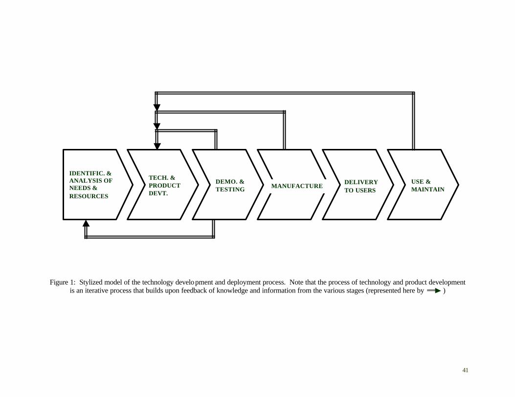
41
Figure 1: Stylized model of the technology development and deployment process. Note that the process of technology and product development
is an iterative process that builds upon feedback of knowledge and information from the various stages (represented here by )
IDENTIFIC. & ANALYSIS OF NEEDS & RESOURCES
MANUFACTURE DELIVERY TO USERS
DEMO. & TESTING
TECH. & PRODUCT DEVT.
USE & MAINTAIN
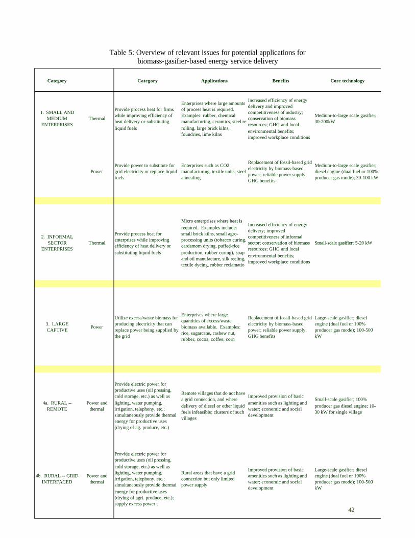
42
Table 5: Overview of relevant issues for potential applications for biomass-gasifier-based energy service delivery
Category Category Applications Benefits Core technology
1. SMALL AND MEDIUM
ENTERPRISESThermal
Provide process heat for firms while improving efficiency of heat delivery or substituting liquid fuels
Enterprises where large amounts of process heat is required. Examples: rubber, chemical manufacturing, ceramics, steel re-rolling, large brick kilns, foundries, lime kilns
Increased efficiency of energy delivery and improved competitiveness of industry; conservation of biomass resources; GHG and local environmental benefits; improved workplace conditions
Medium-to-large scale gasifier; 30-200kW
PowerProvide power to substitute for grid electricity or replace liquid fuels
Enterprises such as CO2 manufacturing, textile units, steel annealing
Replacement of fossil-based grid electricity by biomass-based power; reliable power supply; GHG benefits
Medium-to-large scale gasifier; diesel engine (dual fuel or 100% producer gas mode); 30-100 kW
2. INFORMAL SECTOR
ENTERPRISESThermal
Provide process heat for enterprises while improving efficiency of heat delivery or substituting liquid fuels
Micro enterprises where heat is required. Examples include: small brick kilns, small agro-processing units (tobacco curing, cardamom drying, puffed-rice production, rubber curing), soap and oil manufacture, silk reeling, textile dyeing, rubber reclamatio
Increased efficiency of energy delivery; improved competitiveness of informal sector; conservation of biomass resources; GHG and local environmental benefits; improved workplace conditions
Small-scale gasifier; 5-20 kW
3. LARGE CAPTIVE
Power
Utilize excess/waste biomass for producing electricity that can replace power being supplied by the grid
Enterprises where large quantities of excess/waste biomass available. Examples: rice, sugarcane, cashew nut, rubber, cocoa, coffee, corn
Replacement of fossil-based grid electricity by biomass-based power; reliable power supply; GHG benefits
Large-scale gasifier; diesel engine (dual fuel or 100% producer gas mode); 100-500 kW
4a. RURAL -- REMOTE
Power and thermal
Provide electric power for productive uses (oil pressing, cold storage, etc.) as well as lighting, water pumping, irrigation, telephony, etc.; simultaneously provide thermal energy for productive uses (drying of ag. produce, etc.)
Remote villages that do not have a grid connection, and where delivery of diesel or other liquid fuels infeasible; clusters of such villages
Improved provision of basic amenities such as lighting and water; economic and social development
Small-scale gasifier; 100% producer gas diesel engine; 10-30 kW for single village
4b. RURAL -- GRID-INTERFACED
Power and thermal
Provide electric power for productive uses (oil pressing, cold storage, etc.) as well as lighting, water pumping, irrigation, telephony, etc.; simultaneously provide thermal energy for productive uses (drying of agri. produce, etc.); supply excess power t
Rural areas that have a grid connection but only limited power supply
Improved provision of basic amenities such as lighting and water; economic and social development
Large-scale gasifier; diesel engine (dual fuel or 100% producer gas mode); 100-500 kW
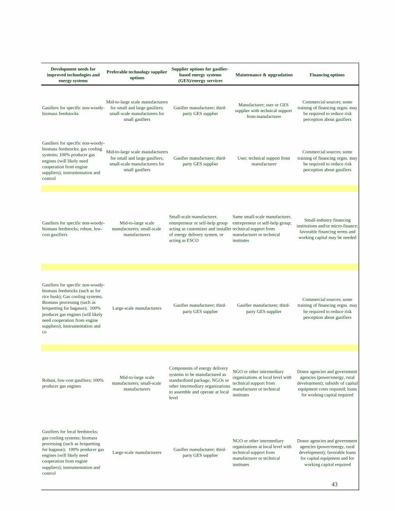
43
Development needs for improved technologies and
energy systems
Preferable technology supplier options
Supplier options for gasifier-based energy systems (GES)/energy services
Maintenance & upgradation Financing options
Gasifiers for specific non-woody-biomass feedstocks
Mid-to-large scale manufacturers for small and large gasifiers; small-scale manufacturers for
small gasifiers
Gasifier manufacturer; third-party GES supplier
Manufacturer; user or GES supplier with technical support
from manufacturer
Commercial sources; some training of financing orgns. may
be required to reduce risk perception about gasifiers
Gasifiers for specific non-woody-biomass feedstocks; gas cooling systems; 100% producer gas engines (will likely need cooperation from engine suppliers); instrumentation and control
Mid-to-large scale manufacturers for small and large gasifiers; small-scale manufacturers for
small gasifiers
Gasifier manufacturer; third-party GES supplier
User; technical support from manufacturer
Commercial sources; some training of financing orgns. may
be required to reduce risk perception about gasifiers
Gasifiers for specific non-woody-biomass feedstocks; robust, low-cost gasifiers
Mid-to-large scale manufacturers; small-scale
manufacturers
Small-scale manufacturer, entrepreneur or self-help group acting as customizer and installer of energy delivery system, or acting as ESCO
Same small-scale manufacturer, entrepreneur or self-help group; technical support from manufacturer or technical institutes
Small-industry financing institutions and/or micro-finance;
favorable financing terms and working capital may be needed
Gasifiers for specific non-woody-biomass feedstocks (such as for rice husk); Gas cooling systems; Biomass processing (such as briquetting for bagasse); 100% producer gas engines (will likely need cooperation from engine suppliers); Instrumentation and co
Large-scale manufacturersGasifier manufacturer; third-
party GES supplier Gasifier manufacturer; third-
party GES supplier
Commercial sources; some training of financing orgns. may
be required to reduce risk perception about gasifiers
Robust, low-cost gasifiers; 100% producer gas engines
Mid-to-large scale manufacturers; small-scale
manufacturers
Components of energy delivery systems to be manufactured as standardized package; NGOs or other intermediary organizations to assemble and operate at local level
NGO or other intermediary organizations at local level with technical support from manufacturer or technical institutes
Donor agencies and government agencies (power/energy, rural
development); subsidy of capital equipment costs required; loans
for working capital required
Gasifiers for local feedstocks; gas cooling systems; biomass processing (such as briquetting for bagasse); 100% producer gas engines (will likely need cooperation from engine suppliers); instrumentation and control
Large-scale manufacturersGasifier manufacturer; third-
party GES supplier
NGO or other intermediary organizations at local level with technical support from manufacturer or technical institutes
Donor agencies and government agencies (power/energy, rural development); favorable loans for capital equipment and for
working capital required
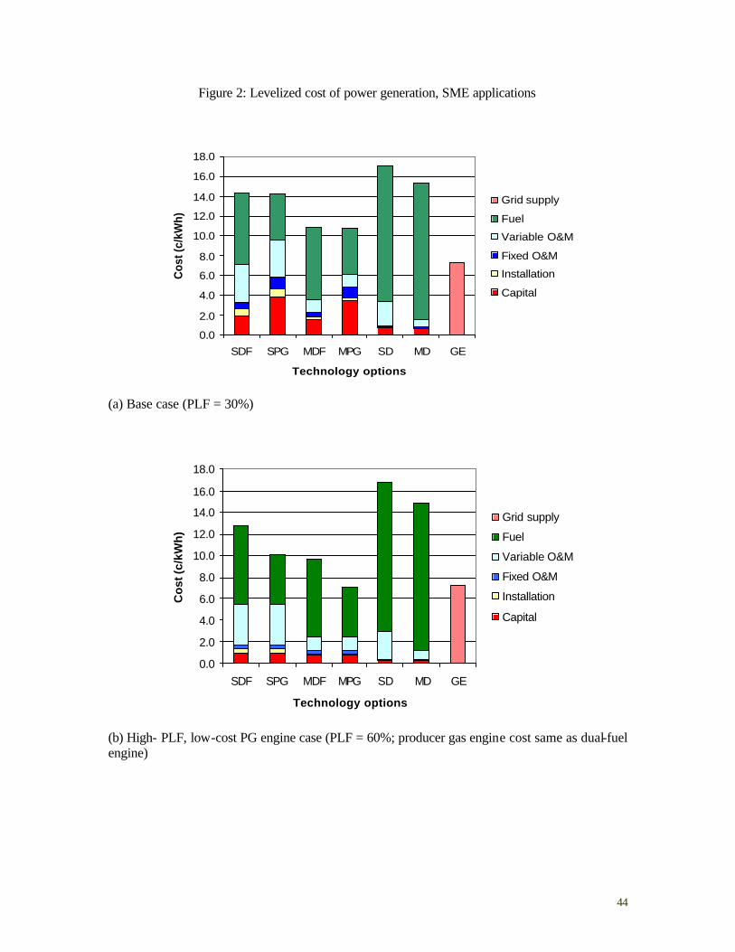
44
Figure 2: Levelized cost of power generation, SME applications
0.0
2.0
4.0
6.0
8.0
10.0
12.0
14.0
16.0
18.0
SDF SPG MDF MPG SD MD GE
Technology options
Cos
t (c/
kWh)
Grid supply
Fuel
Variable O&M
Fixed O&M
Installation
Capital
(a) Base case (PLF = 30%)
0.0
2.0
4.0
6.0
8.0
10.0
12.0
14.0
16.0
18.0
SDF SPG MDF MPG SD MD GE
Technology options
Co
st (c
/kW
h)
Grid supply
Fuel
Variable O&M
Fixed O&M
Installation
Capital
(b) High- PLF, low-cost PG engine case (PLF = 60%; producer gas engine cost same as dual-fuel engine)
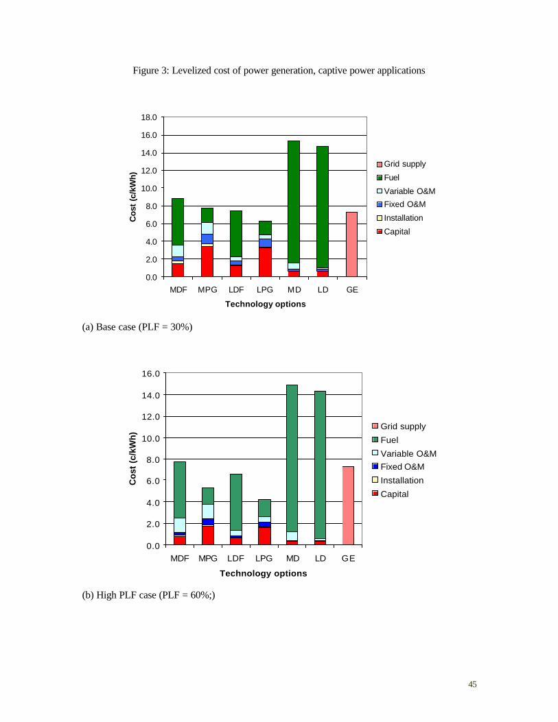
45
Figure 3: Levelized cost of power generation, captive power applications
0.0
2.0
4.0
6.0
8.0
10.0
12.0
14.0
16.0
18.0
MDF MPG LDF LPG MD LD GE
Technology options
Cos
t (c
/kW
h)
Grid supply
Fuel
Variable O&M
Fixed O&M
Installation
Capital
(a) Base case (PLF = 30%)
0.0
2.0
4.0
6.0
8.0
10.0
12.0
14.0
16.0
MDF MPG LDF LPG MD LD GE
Technology options
Cos
t (c
/kW
h)
Grid supply
Fuel
Variable O&MFixed O&M
Installation
Capital
(b) High PLF case (PLF = 60%;)
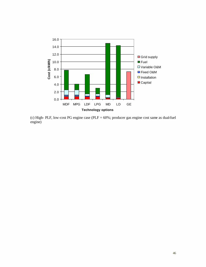
46
0.0
2.0
4.0
6.0
8.0
10.0
12.0
14.0
16.0
MDF MPG LDF LPG MD LD GE
Technology options
Co
st (
c/kW
h)
Grid supply
Fuel
Variable O&M
Fixed O&M
Installation
Capital
(c) High- PLF, low-cost PG engine case (PLF = 60%; producer gas engine cost same as dual-fuel engine)
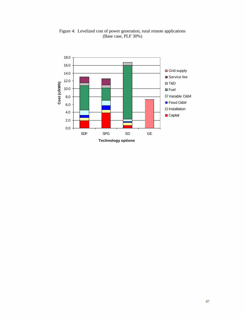
47
Figure 4: Levelized cost of power generation, rural remote applications (Base case, PLF 30%)
0.0
2.0
4.0
6.0
8.0
10.0
12.0
14.0
16.0
18.0
SDF SPG SD GE
Technology options
Co
st (c
/kW
h)
Grid supply
Service fee
T&D
Fuel
Variable O&M
Fixed O&M
Installation
Capital
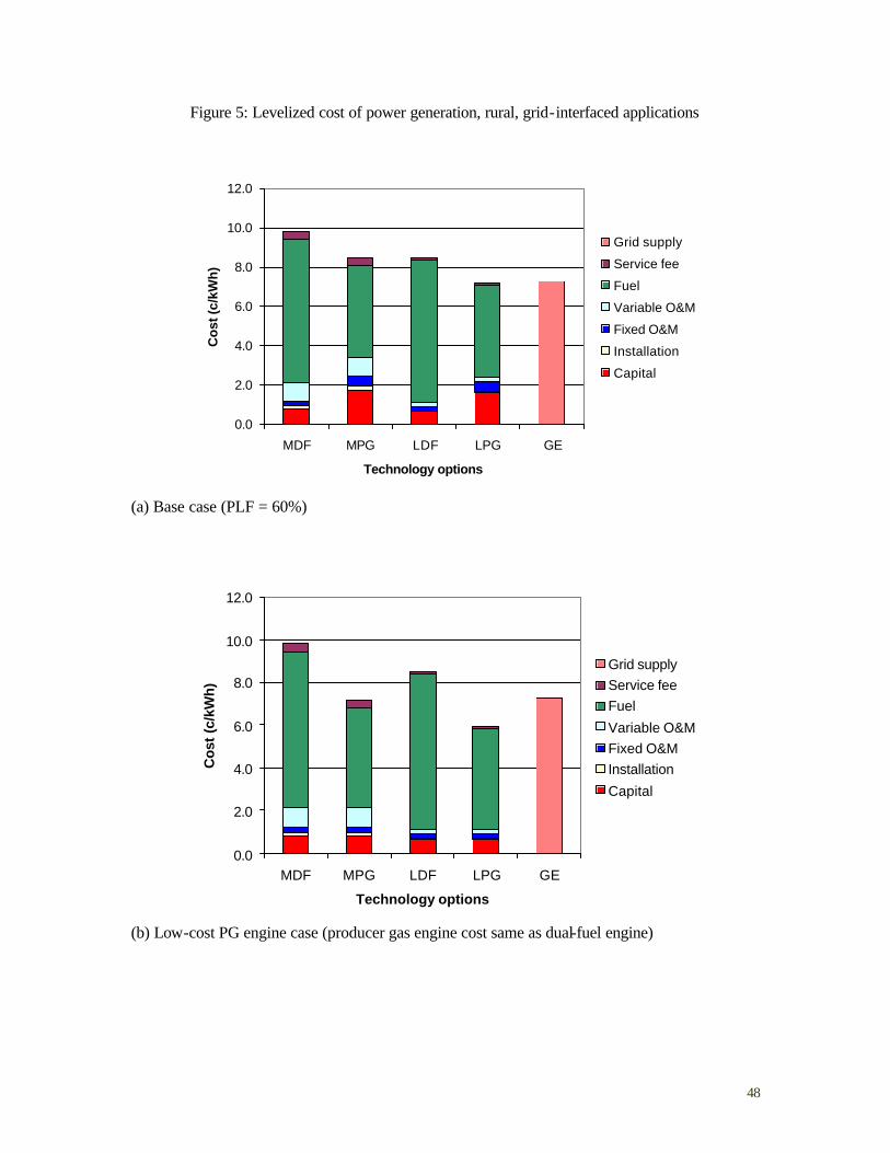
48
Figure 5: Levelized cost of power generation, rural, grid-interfaced applications
0.0
2.0
4.0
6.0
8.0
10.0
12.0
MDF MPG LDF LPG GE
Technology options
Co
st (c
/kW
h)
Grid supply
Service fee
Fuel
Variable O&M
Fixed O&M
Installation
Capital
(a) Base case (PLF = 60%)
0.0
2.0
4.0
6.0
8.0
10.0
12.0
MDF MPG LDF LPG GE
Technology options
Cos
t (c
/kW
h)
Grid supplyService feeFuel
Variable O&MFixed O&MInstallation
Capital
(b) Low-cost PG engine case (producer gas engine cost same as dual-fuel engine)
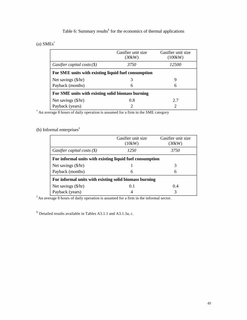
49
Table 6: Summary results§ for the economics of thermal applications
(a) SMEs†
Gasifier unit size (30kW)
Gasifier unit size (100kW)
Gasifier capital costs ($) 3750 12500
For SME units with existing liquid fuel consumption
Net savings ($/hr) 3 9 Payback (months) 6 6
For SME units with existing solid biomass burning
Net savings ($/hr) 0.8 2.7 Payback (years) 2 2
† An average 8 hours of daily operation is assumed for a firm in the SME category
(b) Informal enterprises‡
Gasifier unit size (10kW)
Gasifier unit size (30kW)
Gasifier capital costs ($) 1250 3750
For informal units with existing liquid fuel consumption Net savings ($/hr) 1 3 Payback (months) 6 6
For informal units with existing solid biomass burning Net savings ($/hr) 0.1 0.4 Payback (years) 4 3
‡ An average 8 hours of daily operation is assumed for a firm in the informal sector. § Detailed results available in Tables A3.1.1 and A3.1.3a, c.
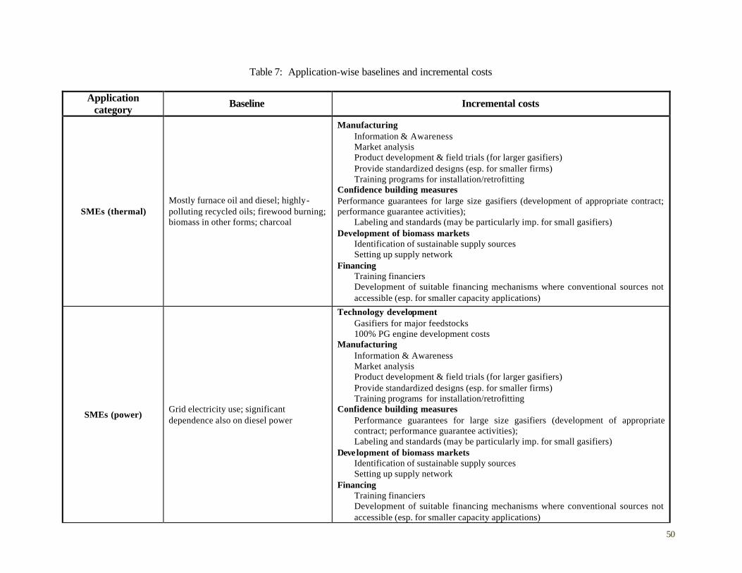
50
Table 7: Application-wise baselines and incremental costs
Application category Baseline Incremental costs
SMEs (thermal) Mostly furnace oil and diesel; highly-polluting recycled oils; firewood burning; biomass in other forms; charcoal
Manufacturing Information & Awareness Market analysis Product development & field trials (for larger gasifiers) Provide standardized designs (esp. for smaller firms) Training programs for installation/retrofitting
Confidence building measures Performance guarantees for large size gasifiers (development of appropriate contract; performance guarantee activities);
Labeling and standards (may be particularly imp. for small gasifiers) Development of biomass markets
Identification of sustainable supply sources Setting up supply network
Financing Training financiers Development of suitable financing mechanisms where conventional sources not accessible (esp. for smaller capacity applications)
SMEs (power) Grid electricity use; significant dependence also on diesel power
Technology development Gasifiers for major feedstocks 100% PG engine development costs
Manufacturing Information & Awareness Market analysis Product development & field trials (for larger gasifiers) Provide standardized designs (esp. for smaller firms) Training programs for installation/retrofitting
Confidence building measures Performance guarantees for large size gasifiers (development of appropriate contract; performance guarantee activities); Labeling and standards (may be particularly imp. for small gasifiers)
Development of biomass markets Identification of sustainable supply sources Setting up supply network
Financing Training financiers Development of suitable financing mechanisms where conventional sources not accessible (esp. for smaller capacity applications)
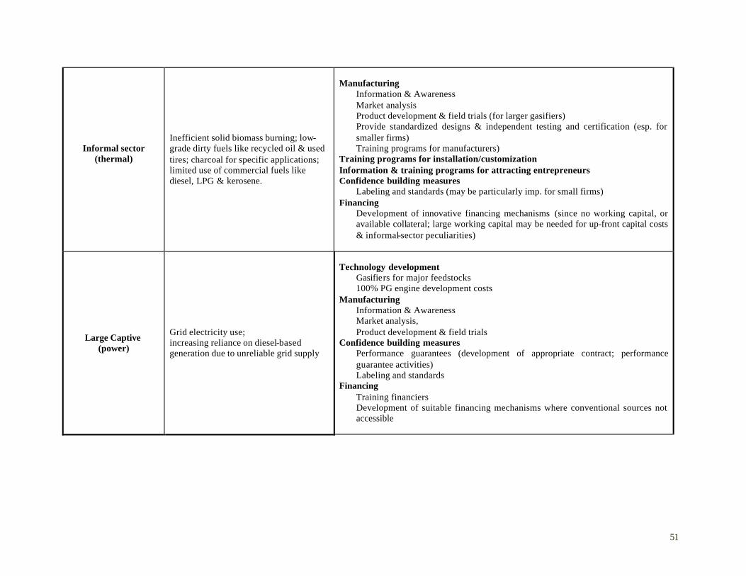
51
Informal sector (thermal)
Inefficient solid biomass burning; low-grade dirty fuels like recycled oil & used tires; charcoal for specific applications; limited use of commercial fuels like diesel, LPG & kerosene.
Manufacturing Information & Awareness Market analysis Product development & field trials (for larger gasifiers) Provide standardized designs & independent testing and certification (esp. for smaller firms) Training programs for manufacturers)
Training programs for installation/customization Information & training programs for attracting entrepreneurs Confidence building measures
Labeling and standards (may be particularly imp. for small firms) Financing
Development of innovative financing mechanisms (since no working capital, or available collateral; large working capital may be needed for up-front capital costs & informal-sector peculiarities)
Large Captive (power)
Grid electricity use; increasing reliance on diesel-based generation due to unreliable grid supply
Technology development Gasifiers for major feedstocks 100% PG engine development costs
Manufacturing Information & Awareness Market analysis, Product development & field trials
Confidence building measures Performance guarantees (development of appropriate contract; performance guarantee activities) Labeling and standards
Financing Training financiers Development of suitable financing mechanisms where conventional sources not accessible
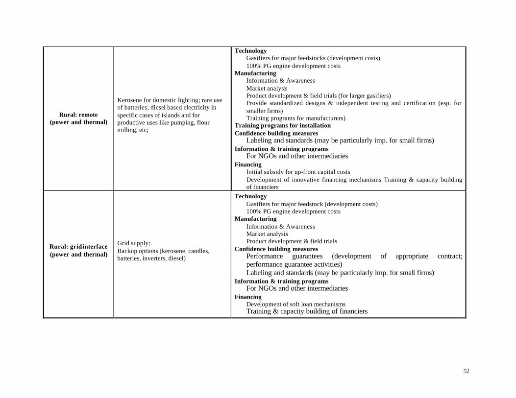
52
Rural: remote (power and thermal)
Kerosene for domestic lighting; rare use of batteries; diesel-based electricity in specific cases of islands and for productive uses like pumping, flour milling, etc;
Technology Gasifiers for major feedstocks (development costs) 100% PG engine development costs
Manufacturing Information & Awareness Market analysis Product development & field trials (for larger gasifiers) Provide standardized designs & independent testing and certification (esp. for smaller firms) Training programs for manufacturers)
Training programs for installation Confidence building measures
Labeling and standards (may be particularly imp. for small firms) Information & training programs
For NGOs and other intermediaries Financing
Initial subsidy for up-front capital costs Development of innovative financing mechanisms Training & capacity building of financiers
Rural: grid-interface (power and thermal)
Grid supply; Backup options (kerosene, candles, batteries, inverters, diesel)
Technology Gasifiers for major feedstock (development costs) 100% PG engine development costs
Manufacturing Information & Awareness Market analysis Product development & field trials
Confidence building measures Performance guarantees (development of appropriate contract; performance guarantee activities) Labeling and standards (may be particularly imp. for small firms)
Information & training programs For NGOs and other intermediaries
Financing Development of soft loan mechanisms Training & capacity building of financiers
53
5. CONCLUSION
There is an enormous potential to utilize GESs for the provision of energy services for a range of applications in developing countries. Based on our analysis of the substantial Indian experience with this technology, a number of applications appear particularly amenable to the scaled-up application of GESs. At the same time, it is apparent that the scale -up approach has to be application-specific because of the variations in the energy service needs across applications as well as the availability of biomass, financial, human, institutional and other resources. Yet, there are a number of factors to which attention will have to be paid for deployment in any application. These include: technology and product design, manufacturing, product uptake, operation, maintenance and servicing, biomass supply, and, of course, financing. While different applications may require differing levels of emphasis on different elements, none of these can be ignored if dissemination is to be successful. At the same time, attention has to be paid to the overarching issues such as information and awareness programs, learning from field experiences, and actor interactions that will determine the long-term effectiveness of any overall program of GES deployment. Table 8 reviews suggested categories of applications that could serve as suitable startin g points for a program aimed at large-scale deployment of biomass gasifiers and key areas where interventions will be required to assist in this process. We suggest that perhaps the most fruitful scale -up strategy would be one that initially focuses on pure thermal productive applications. These could be taken up in the short-term, given their economic and financial feasibility and only minor needs for technology development. At the same time, a sequenced approach could be followed for power generation applications. Here, selected pilot transactions could be initiated with a view to prompting appropriate technology and product development and also provide learning about how to best incorporate such efforts into existing institutional structures for electricity provision. As successful products and institutional delivery models emerge, scale -up would follow for such applications.
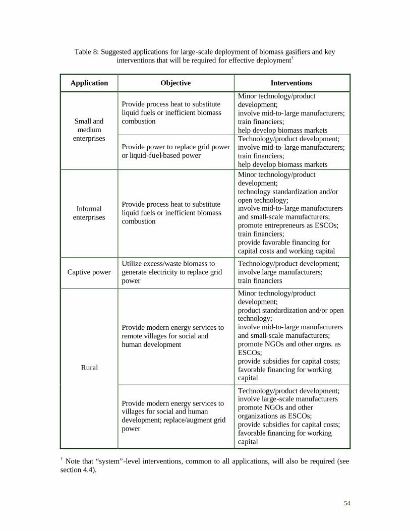
54
Table 8: Suggested applications for large-scale deployment of biomass gasifiers and key interventions that will be required for effective deployment†
Application Objective Interventions
Provide process heat to substitute liquid fuels or inefficient biomass combustion
Minor technology/product development; involve mid-to-large manufacturers; train financiers; help develop biomass markets
Small and medium
enterprises Provide power to replace grid power or liquid-fuel-based power
Technology/product development; involve mid-to-large manufacturers; train financiers; help develop biomass markets
Informal enterprises
Provide process heat to substitute liquid fuels or inefficient biomass combustion
Minor technology/product development; technology standardization and/or open technology; involve mid-to-large manufacturers and small-scale manufacturers; promote entrepreneurs as ESCOs; train financiers; provide favorable financing for capital costs and working capital
Captive power Utilize excess/waste biomass to generate electricity to replace grid power
Technology/product development; involve large manufacturers; train financiers
Provide modern energy services to remote villages for social and human development
Minor technology/product development; product standardization and/or open technology; involve mid-to-large manufacturers and small-scale manufacturers; promote NGOs and other orgns. as ESCOs; provide subsidies for capital costs; favorable financing for working capital
Rural
Provide modern energy services to villages for social and human development; replace/augment grid power
Technology/product development; involve large-scale manufacturers promote NGOs and other organizations as ESCOs; provide subsidies for capital costs; favorable financing for working capital
† Note that “system”-level interventions, common to all applications, will also be required (see section 4.4).
55
ANNEXURE 1. B IOMASS GASIFICATION: A TECHNOLOGY PRIMER-CUM-GLOSSARY 32
A1.1 Biomass Gasification
A process in which biomass (usually dry, with moisture contents less than 20%) is converted into a mixture of gases (called producer gas) consisting of combustible gases (mainly hydrogen, carbon monoxide and methane), non-combustible gases (nitrogen, carbon dioxide), and water vapor. A1.2 Gasifiable Material
Sized, relatively dry, firewood (prosopis juliflo ra, eucalyptus, casurina, acacia, neem wood, mango wood, etc); wood-like materials such as corncobs, lantana (a wildly-growing weed), Ipomea, mulberry sticks; coconut shells, cashew shells, biomass briquettes, and rice husk. Most naturally available biomass materials have similar elemental composition (C,H,O) on an ash-free and moisture-free basis. Hence all these materials can be gasified in suitably designed reactors (gasifiers). But physical and physico-chemical properties such as bulk density, ash content, ash melting point, presence of fines, thickness of bark, and shape of biomass materials vary widely and it is generally not possible to gasify all kinds of materials in the same gasifier. Hence it is best to design/optimize a gasifier for a specific biomass and for a specific application. A1.3 Gasifier
A reactor in which biomass can be converted through a thermo-chemical reaction under controlled conditions, to yield an uninterrupted flow of producer gas. Air (or oxygen) required for gasification is generally fed into the gasifier either through a blower or by creating suction from the downstream side of gas exit. After ignition, the various zones in the gasifier attain certain equilibrium temperatures, after which both the production rate and quality (composition, etc.) of the producer gas become steady. Several types of gasifiers exist: fluidized bed gasifiers, entrained bed gasifiers, circulating fluidized bed (CFB) gasifiers, and moving bed gasifiers. The first three types are generally used for large-scale industrial applications and for pulverized coal or similarly-sized biomass (e.g., rice husk). In the context of the present report, moving bed gasifiers are the most relevant.33 Moving bed gasifiers can again be classified as four types: downdraft (or co-current; fuel flow and gas flow in the same direction), updraft (or countercurrent; fuel flow and gas flow in opposite directions), cross draft (gas flow perpendicular to fuel flow) and natural draft (gas flow induced by natural draft, hence no need for a blower). In the downdraft gasifiers, air enters through nozzles or tuyeres placed about 30-50 cm above the grate. In the so-called open-top gasifier or stratified downdraft gasifier (originally conceived at the Solar Energy Research Institute (now the National Renewable Energy Laboratory) and developed further at the Indian Institute of Science, IISc), some air enters from top, and some
32 Information in this annexure is based on authors’ own knowledge and experiences, unless otherwise stated. 33 These are sometimes also called fixed-bed gasifiers, but such a nomenclature is somewhat misleading. The fuel-bed height keeps decreasing as gasification progresses, and fuel has to be charged into the reactor once the bed height goes below a certain critical level decided by the various zone heights within the gasifier.
56
through nozzles. In the updraft and natural draft gasifiers, there are no nozzles, and all the air enters through the grate at the bottom. Ignition, and subsequent sustained combustion occurs near the nozzles for the downdraft design and on the grate for the updraft design. Consequently, the vertical temperature profiles are different for the two designs. While the temperature increases steadily from the top of the fuel bed to the grate in the updraft design, there is a ‘kink’ in the temperature profile at the nozzle location for the downdraft design. The original, second world-war downdraft designs (also called the classical ‘Imbert’ type designs) used a ‘throat’ or constriction in the gasifier just below the nozzle location. The idea was to pass the ‘tars’ through a high temperature, narrow region so that they can be ‘cracked’ (i.e., broken down to simpler molecules like methane). Gasifiers with throats are not conducive for smooth flow of biomass, especially for small-capacity systems, and are highly sensitive to biomass size. Throat less designs are believed to overcome these problems, but as will be discussed later, the fuel movement problems still seem to persist in almost all designs. Whether the gasifier is downdraft or updraft, the gasification process is complete within 1m starting from the grate. If the gasifier is much taller than this, it is because enough fuel has to be stored in the ‘hopper’ to last for certain number of hours. The cross-sectional area at the nozzle location for downdraft designs and at the grate for updraft designs is a measure of the throughput of the gasifier and hence is an indication of the capacity. One of the most important design parameters for gasifiers is the Specific Gasification Rate (SGR), sometimes called grate loading for updraft gasifiers, expressed variously in the units of Nm3/(hr)(cm2) or kg/(hr)(m2) or m/s. (Note: Nm3 is read as normal meter cube, meaning the volume of gas normalized to 0 0C and 1 atm.). One kg of biomass produces about 2.5-3.0 Nm3 of gas and hence it is relatively simple to calculate the cross-sectional area for a given throughput if the SGR is known. Depending on whether the air is pushed or sucked34 through it, the gasifier operates at a pressure either slightly higher or slightly lower than the atmospheric pressure respectively. These modes of operation are loosely termed as ‘pressure mode’ or ‘suction mode’. For a gasifier operating under pressure mode, the blower has to be stopped at the time of charging the biomass, so the gasifier operation will be briefly interrupted. Gasifiers for applications requiring only a few hours of operation in a day, such as small enterprises or rural power plants, biomass can be charged at the beginning or at the end of operation. For a gasifier operating in the suction mode, however, opening a door or fuel port might result in a temporary change in the quality of the gas, but the gasifier operation need not be interrupted. There are other advantages and drawbacks of both modes of operation, which will not be elaborated in this report. Irrespective of the type, all gasifiers have somewhat distinctive zones characterized by different processes. These are drying, pyrolys is, combustion and reduction zones. It is helpful to understand these zones in some detail. Drying
Drying is characterized by release of moisture, though it is not same as sun-drying or air-drying. Each biomass material may have a typical “drying rate curve” which tells how the drying rate progresses with decrease in solid moisture. Typical drying times (from about 35% to 10%
34 This suction can be created through the action of a blower or by the downward stroke of the piston in an internal combustion engine that is connected to the gasifier.
57
moisture content) vary from 24 hrs to 72 hrs depending on temperature, air humidity, air velocity, size, etc. For practical reasons, most gasifier designs are sized in such a manner as to allow the biomass to reside in the gasifier for only a few (4-8) hrs. Hence, irrespective of design, it is generally not feasible to dry the biomass to the degree required within the gasifier. Put differently, the gasification of very wet biomass or green biomass (freshly cut or freshly harvested) is generally a very tough proposition. Attempts to do so would normally result in production of a lot of smoke, very low quality (lean) gas, and unstable operation. This also means that gasifier users would be better off if they install an extraneous drying system or store enough dry biomass for several days of operation. Pyrolysis
This is the process in which heating of the biomass at high temperatures (usually in the range of 350-450 ºC) results in the production of a mixture of gases, volatiles and vapors (termed ‘pyrolysis gases’). The ‘ pyrolysis zone’ in a gasifier refers to the space in which release of volatiles is nearly complete. The inflow into this space is mostly-dry biomass and steam and the outflow is pyrolysis gases and charcoal. Apart from known combustible gases like hydrogen, these gases consist of hundreds of organic compounds, water vapor, soot, etc. The origin of impurities, such as tar and particulate matter, in the producer gas can be traced to the pyrolysis zone. Combustion zone
It is difficult to say what exactly burns in the combustion zone of a gasifier. By the time the original biomass reaches the combustion zone, much of it would have become charcoal; hence it is logical to assume that a large part of pyrolysis gases and a small part of the charcoal burn in the presence of oxygen in this zone. In the downdraft gasifier, flaming pyrolysis (i.e., the burning of the pyrolysis gases) can actually be seen through the nozzles and the presence of a bright orange or yellow glow is indicative of healthy and smooth functioning of the gasifier. The reaction in the combustion zone is usually represented as C + O2 ? CO2
but this is an over-simplification of the processes occurring in the zone. Reduction Zone
This is the zone where the main reactions leading to the formation of producer gas occur. Again, the reactions occurring will be quite complex, but can be simplified as the following: Reduction or ‘Boudard’ reaction : C + CO2 ? 2 CO (carbon dioxide combines with char to produce carbon monoxide) Water gas reaction: C + H2O ? CO + H2 (water vapor passing over hot charcoal produces carbon monoxide and hydrogen) Shift reaction: CO2 + H2 ? CO + H2O (carbon monoxide and hydrogen achieve a balance in this reversible reaction) Methanation reaction: C + 2 H2 ? CH4 (hydrogen combines with char to produce methane) One should note that oxygen is supposed to be consumed completely in the combustion zone.
58
In the downdraft gasifiers, the combustion products, along with impurities, pass through a high-temperature zone prior to gasification, and hence the impurities get partially cracked. Hence the impurity levels in the final gases are somewhat less. In the updraft gasifiers, the combustion products go through relatively lower-temperature zones and cracking does not occur. Hence the impurity levels in the final gas stream are much higher. A1.4 Tar and Particulate matter (TPM) in producer gas
These are the byproducts of biomass burning (and generally any solid-fuel combustion) and consist of hundreds of organic compounds, soot, ash, and water vapor. These impurities are generally not very different from what one sees in a wood smoke. They are often thought of as separate entities, which can be ‘removed’ by a particular method or equipment in a piecemeal way but the understanding of these impurities is still evolving. For convenience sake, one can classify the impurities as low boiling tars (benzene, toluene etc. – in fact not tars at all), high boiling tars, particles (both soot and ash) with a given size distribution ranging from sub-micron level to a few hundred microns, and aerosols which are a conglomeration of various impurities. TPM has a deleterious effect on the engine intake manifold and ultimately damage the engine. Typically, lubricating oil deteriorates very fast, engine valves get clogged and cylinder linings get damaged if there are excessive impurities in the gas. Hence, this need to be reduced to acceptable levels in the producer has before it is admitted into an engine. However, there is no clear understanding of these ‘acceptable’ levels. A few European and other research institutes seem to agree on levels of 50 parts per million (ppm; approximately same as mg/Nm3) for tar and 100 ppm for dust (particulate matter). But most engine manufacturers in India are wary of feeding producer gas into their engines and ask for zero impurities. Recently one of them conceded to about 5 ppm of tar. Raw gases from most downdraft gasifiers contain a few thousand ppm of impurities and gases from updraft gasifiers can contain an order of magnitude higher impurities. Hence the gas cleaning systems required for updraft gasif iers are much more elaborate than those required for downdraft gasifiers. Added to the complexity of the nature of impurities, there were questions relating to quantitative determination until recently. Comparison of results from newer methods such as the Swiss method with those from old methods such as the filter paper method used extensively for field testing and certification have opened up questions regarding re-validation of existing certified manufacturers. A1.5 The Gas Cooling and Cleaning train
This refers to a series of components to cool and clean the raw gas before it can be admitted to an engine. Hot gases have a lower calorific value than cold gases on a volumetric basis and hence they have to be cooled in order not to derate the power significantly. A variety of equipment such as cyclones, wet cyclones, absorption columns (with and without packings), venturi scrubbers, saw dust filters, sand-bed filters, bag house filters, or paper filters are used to achieve the required cleaning. Most systems need water for the operations, which usually results in generation of waste-water. Not much work has been done on treatment and safe disposal of this waste-water. The impurities also clog the various components over time and hence lead to frequent maintenance problems. Also, if the train is too long or complicated, the pressure drop across the system is too high, requiring additional blowers. It generally is a tough proposition to achieve a good balance between gas cleaning goals, pressure drop, waste stream generation, parasitic power, and need for excessive maintenance. The design of the cooling and cleaning train has so far been quite empirical and non-standard. However, the understanding of the nature of
59
impurities, both in qualitative and quantitative terms, has been improving in recent years – this might pave the way for a more systematic design of the gas cleaning train. A1.6 Engines
Engines convert heat (or thermal energy) into shaft power (mechanical energy), which can then be used to generate electricity. The conversion routes from producer gas to electricity can be many, including use of an external combustion engine like Stirling engine, use of steam turbine through a steam route, catalytic conversion to hydrogen and then feeding to a fuel cell, or use of an internal combustion engine. Internal combustion engines are further classified as spark ignition (SI) engines and compression ignition (CI) engines. Now gas turbines are also being considered as desirable alternatives. So far producer gas has largely been used in diesel engines (a CI engine) in dual-fuel mode (i.e., simultaneously using diesel and producer gas) giving a diesel replacement of about 70%. However, a relatively steep increase in diesel prices, considerations of access to diesel in remote villages, and considerations of self-reliance led to some efforts to develop a 100%-producer-gas engine in recent years. These efforts include the use of natural gas engines with little modifications and the modification of diesel engines to run as SI engines. However, it should be noted that such modifications have been made by research institutions and gasifier manufacturers and do not have the concurrence or stamp of engine manufacturers and designers. There seems to be a consensus that fresh and serious efforts would have to be launched to develop an engine “designed” for 100%-producer-gas operation. A1.7 Typical operational and other problems of gasifier systems
A typical starting problem of the gasifier is that after the ignition of the fue l bed, continuous and stable gas production does not occur, even after prolonged torching of the fuel bed. This almost always happens if the fuel is very wet. Sometimes, even though the gasifier can be started without any problem, gas production will either cease or gas quality will deteriorate (lean gas, smoky, and unable to sustain combustion). The two main reasons for this are bridging and clinker formation. Bridging is caused if all the fuel in the vicinity of air entry is burnt out and no fresh fuel drops into the empty space thus created. There could be several reasons for this but unless the bridge is broken by poking the fuel bed or shaking the grate or the gasifier itself, gas production will not resume. The operator usually resorts to opening the top of the gasifier and poking the fuel bed with a long rod. Some gasifier manufacturers provide openings or ports on the sides of the gasifier so that one does not have to use a long rod. Some designs try to overcome this problem by insisting on a certain size of the fuel but it is not very practical to obtain consistent size always unless good care is taken for fuel preparation. Clinker formation occurs if the ashes contained in the biomass melt easily. Clinker usually develops over time, almost always near the nozzles or grate where combustion occurs. Many times this occurs when the gasifier is re-started after allowing it to cool overnight. Clinker-formation is particularly difficult to handle because it cannot be observed visually, and if it is suspected after the bed is completely charged, it is an arduous task to remove the fuel and then try to break the clinker into pieces so that the pieces can be pushed through the grate. Coconut shells with fiber, firewood with bark, cashew shells, and briquettes are usually susceptible for clinker formation.
60
Another problem which occurs is the build-up of ash on the grate, especially for high ash fuels like rice husk. A very effective continuous ash removal system has to be designed to tackle this problem. In all the above cases, fresh fuel does not fall into the combustion zone, and the circular chain ‘ fuel-air-temperature’ breaks, and gas production ceases. Another frequent problem interrupting stable and continuous gas production is related to deposition of impurities anywhere in the gas cleaning and cooling train. Such depositions lead to an increase in pressure drop and reduce the gas flow rate and ultimately prevent operation of the gasifier. Attempts to continue operation by keeping the blower on and tinkering with the system without making an educated guess or without a measured parameter that indicates the location and nature of the problem often result in accumulation of gases in the reactor leading to an explosion. Most gasifiers experience explosions (or back-fire) at some point during their operating lifetime. Fortunately, the explosions are not very strong but can unnerve a new or untrained operator or user. As gasifiers are high temperature reactors and the resulting gases are corrosive in nature, it is quite logical that many kinds of material problems occur and questions about the lifetime of the various components keep arising. Some attempts have been made to analyze these problems but there are no standard material selection procedures or codes to be followed. It is generally assumed (erroneously) that by using stainless steel (AISI 304) all materials problems can be solved. Many manufacturers tend to cut corners by using mild steel (MS) without adequate thickness or by using scrap material. Any future attempts of technology or component standardization should include a thorough study of the suitability of different materials for different parts of the gasifier system. Following early leads by TERI to use high-temperature castables, many manufacturers use such materials at present, but there are no set standards yet.
61
ANNEXURE 2. SELECTED ASPECTS OF THE INDIAN EXPERIENCE35
A2.1 A Review of Technology Developments in India
A2.1.1 How much has the technology matured?
A frequent complaint with the gasifier system is that it works as long as the team that developed it (usually a team of scientists) is attending to it. There are not many instances in which this kind of handholding has not occurred over a prolonged period, sometimes covering the useful life of the system. The handholding has been somewhat less in systems that are sold on commercial basis to industrial users of thermal systems (CO2 manufacture, MgCl2 manufacture, textile dying, rubber drying, etc). Some of this can be attributed to user-training needs – experience shows that over time, serious users learn to grapple with the various maintenance problems as much as they can. They might have incentives to do so, having paid for the system and from benefiting substantially from fuel savings. On the other hand, there are users who could not tackle all problems, which might also mean that the developers themselves have not solved the problems conclusively. In such cases, the system runs on and off, but finally stops. There are a few demonstration systems that are being run as showcases and hence have to be maintained at any cost. And then there are systems, which have been ‘acquired’ at marginal or no cost to the user and in such cases the systems just wither off, even though they were potentially viable. So it seems there is neither a simple nor single answer for the question of ‘technology maturation.’ A clear answer might emerge out of a comprehensive, professional, and dispassionate evaluation of the field performance of all the systems installed so far for different applications. A limited study has been conducted for the state of Haryana (Chakravarthy et. al., 1991), but there is a need to carry similar studies for the rest of the country. An attempt is, however, made in the following pages to enumerate some of the known technology issues of biomass gasification. A2.1.2 Experience with different fuels
The maximum experience has been with wood chips. Here, as also stated in Annexure 1, problems have been experienced with non-uniform size, high moisture content, and presence of bark. Problems related to bridging, excessive tar formation, and material failure seem to have been reduced significantly for gasifier sizes of 10-200 kg/hr (roughly corresponding to 10-200 kW for electrical systems) but for larger capacities there are problems of uniform distribution of air through nozzles with the consequent cold spots and increased tar formation. Wood-like material such as Ipomea has been successfully used over prolonged periods at Orchcha. Success with other materials like mulberry sticks is either limited or not completely known. The size of wood chips acceptable in the gasifier seems to depend on its design. The IISc design usually requires a very small size (~1 inch), Ankur and similar designs like AEW require about 2 inches, while TERI designs have operated with larger sizes. The size of wood has implications on the maintenance costs, especially because wood is cut manually and the production rate for such cutting is quite low. Some of the earliest experiences with non-wood biomass were at TERI, which aimed to develop designs for a variety of fuels in a project funded by DNES in 1986. Results indicated that several biomass materials could be gasified if those are in briquetted form. The features which made this possible were low specific gasification rate, better insulation of the reaction zone, and continuous ash removal. In order to remove the not-so-desirable briquetting process, a program (PowBIG,
35 Information in this part is based on authors’ own knowledge and experiences, unless otherwise stated.
62
Powdery Biomass Gasification) was subsequently launched at IISc for gasification of powdery biomass with significant MNES funding, but this did not result in reliable designs. Currently many developers claim that their gasifiers can use briquetted biomass but there is very little field evidence to prove that briquettes can be used reliably over long durations. There have been recent efforts to gasify briquettes made from a mixture of pulverized biomass, petroleum refinery wastes, pellets made from municipal wastes, and other residues but these are confined to laboratory demonstrations. However, considering the large scope biomass briquetting offers for utilizing residues that are otherwise not used economically, efforts should continue to develop and perfect gasifier designs for this purpose. There is a limited success in utilizing coconut shells and cashew shells, mainly for use in the rubber drying factories in Kerala in recent years, but problems of bridging and clinker formation are not yet satisfactorily solved. Gasification of rice husk had a special importance ever since Al Kaupp did his landmark research on the subject. Though rice husk is already used in boilers and other devices, and hence there are some questions of availability in states like Punjab, there is a niche for power generation (and cogeneration) in rice mills which dot the entire country. Except for some early work at Bharathidasan University on fluidized bed gasification of rice husk, there has been no systematic developmental work funded by MNES. Many manufacturers cla im to have developed either updraft (Grain Processing Works) or downdraft (Ankur, AEW) gasifiers but these have not been tested thoroughly. Some IREDA-financed rice-husk-based power projects have defaulted on payments claiming failure of the systems. A downdraft design using a rotating grate has been developed at TERI also and is being tested. Rice husk has a high ash content (~23%), hence a continuous ash removal system is needed for reliable operation. Besides, problems of bridging can also be severe. Excessive tar formation has also been observed, as the temperatures attained in the fuel bed are low. Evaluation of the presently available designs, development and standardization of new designs and some field-testing would be essential for mainstreaming of rice husk gasifier based power plants. A2.1.3 The elusive tar-free gas for engine operation
The crucial importance of clean gas for engine operation has been stressed in Annexure 1. It has been mentioned that one of the problems has been the lack of a standard method for measuring the impurities. As of now the Swiss method seems to be quite comprehensive. There are variations in solvents used and some instrumentation followed by other labs. To the best of our knowledge, only IISc and TERI use this method internally to measure impurities. Gasifier manufacturers who claim ultra pure gas often quote testing carried by some ‘renowned’ agencies or do not say anything about the method. The other, somewhat tricky situation in India is that people who develop gasifiers are also the people who test the systems and this has implications on mainstreaming. Results of testing of several gasifiers are available from the Swiss Federal Institute of Technology (ETH), Zurich. In addition, TERI has conducted several measurements in-house. Some of the broad conclusions arising out of these results are as follows:
• There is a large variation in the impurity levels in the raw gas for the same gasifier design.
• There is a large variation for the clean gas also. • Many times the impurity levels in the clean gas exceed the stipulated norms for
engine operation, which means that if only one test is conducted and the gasifier certified, there is no guarantee that it will not spoil the engine at a later date.
63
• There are sometimes anomalie s such as the impurity levels in clean gas being higher than those in raw gas.
• All the gasifiers tested are comparable in performance, with respect to thermal efficiency and impurity levels. This means that there is no way of ranking any of these gasifiers as superior in comparison with others.
These observations suggest that tar-free gas for engine operation is still elusive and that more work needs to be done to solve the tar problem unambiguously. Development carried out in the GEF project involving TPS Termiska and other partners used catalytic methods for tar cracking but such methods may not be suitable for small gasifiers. Recent work carried out on two-stage gasification at DTI in Denmark shows promise to produce tars of the order of 25 ppm in raw gas, thus eliminating the need for an elaborate cleaning train and hence deserves attention for further development and testing.
A2.1.4 Prototypes and industrially engineered systems
Most gasifiers installed in India look either like prototypes made in a small workshop or very complicated to operate and maintain. Almost all the engineering of the gasifiers is carried out either by the R&D institutions, fabricators, or manufacturers, all of whom have only limited industrial design skills. The only examples where the services of an industrial design center were utilized to improve the final design of an industrial prototype were those of the silk reeling gasifier and the silk dyeing gasifier developed in the TERI/SDC program. Gasifier systems developed by TERI for other applications did not have such inputs. While existing gasifier manufacturers and developers may not agree on the value of further industrial design inputs, but it is more than likely that gasifiers and associated cleaning systems would be better off in terms of finish, material optimization, life of components, ease of use and maintenance, etc. if input is taken from industrial designers. A2.1.5 Off-the-shelf and tailor made components
The complete gasifier “system” consists of several items such as blower, pipes and ducts, couplings, valves and insulation that are available in the open market and certain tailor-made components such as burners, cyclones, scrubbers, mist separators and filters. An exercise to optimize the system for pressure drop, parasitic power, or cost is seldom done. Based on past experience with gasifier systems, we feel that such an exercise would reveal that certain components are unsuitable or inoptimal for their intended use. Some examples:
• The blower that is generally used consumes too much power for the flow rates and pressure drops required, but a blower with the desired characteristics is either not available in that size or is too expensive.
• Mild steel or stainless steel pipes and ducts are generally used because they are readily available in the market, but are not the best to transport hot and corrosive gases. In one instant, the pipe carrying the cooled and cleaned gas corroded fast and it was the rust carried by the gas that damaged the engine, not the impurit ies present in the gas. In another instance, hot gases carried over long distance corroded the stainless steel piping within a month.
• The burner is usually designed by the developer or manufacturer with little or no expertise on this aspect. The design of the burner is crucial to sustain the flame (preventing lift-off or gas burning inside the pipe) and to reduce emissions. Recent experiments have shown that CO levels in the flue gases could go up to 10,000 ppm if the

64
burner is not designed properly. The burners thus need careful design and standardization just as it has been done for LPG burners or natural gas burners.
• The couplings usually leak. • The insulation is often poorly done. • The gasifier system often has scanty instrumentation and control, as mentioned in
Annexure 1. Component and systems-integration aspects are thus central for future mainstreaming. A2.1.6 Issues of industrial safety and environmental compliance
Some important industrial safety issues pertain to exposure to high temperature surfaces, exposure to CO emissions, and prevention (and control) of explosions and backfires. The first item requires good design of the insulating system (and just not wrapping glass-wool sheets as is done too often) and the last two items require good instrumentation and control. Especially if the gas is burning inside a vessel (such as a furnace or a drier), there is a strong possibility that the flame might extinguish during the operation and with the blower on, combustible gases will accumulate in the closed space. So when the burner is restarted, an explosion takes place. A control mechanism that stops the blower if the flame extinguishes or a pilot injection, which will always allow the gas to burn, is thus highly desirable. Similarly when people are working in restricted spaces and if leakage of gases occurs, they will be exposed to dangerous emissions. It is required that CO alarms be installed in such situations but this is not usually done. Environmental compliance issues pertain to emission levels of exhaust gases and wastewater treatment. CO emissions from producer gas engines, especially 100% gas engines, can easily exceed emission norms if catalytic converters are not employed. Water is used for scrubbing the gas and cooling and if the tar levels in the gas are very high (especially for updraft gasifiers), highly polluted wastewaters are produced. Chemical oxygen demand (COD) levels of up to 70,000 mg/lit have been observed in wastewaters from gasifiers and these waste streams are generally not treated at present. A2.1.7 Engine development
As mentioned earlier, there are no engines developed exclusively for producer gas use. When natural gas engines or diesel engines are converted to operate on producer gas, there are problems of de-rating (loss of power), low conversion efficiency, speed control, knocking, emissions control, and engine life. 100% producer gas engines currently being claimed as developed are really crude prototypes. The effort required for the development of reliable and efficient engines is likely to be quite substantial and will have to include more than cursory involvement of engine designers and manufacturers as is the case at present. A2.1.8 Testing and Certification
This is a contentious and delicate issue and seems to have reached some kind of a deadlock. After review of previous methods of testing and deliberations lasting about 18 months and several meetings, MNES came up with testing methods and standards that are elaborate, cumbersome, and rigid. After these exercises, the existing GARPS, that were also the testing agencies, were terminated and hence there is no institution at present to test and certify gasifiers. The prickly issue was that the same groups were developing, commercializing and certifying the systems. Gasifier manufacturers who had their own designs or who got the designs from institutes other than GARPS are either wary of them or feel they have been subject to unfair, individualistic

65
treatment. Meanwhile, the so-called ‘approved’ manufacturers rule the scene and dominate the existing subsidy market. Under the circumstances, it seems absolutely essential to:
• establish an independent, sustainable and non-governmental agency for testing and certification,
• simplify the testing methods and to establish realistic testing standards, • promote an open door policy to encourage many more manufacturers and entrepreneurs.
A2.1.9 Visioning for Volume Production
The fact that several entrepreneurs and manufacturers have started setting up and even selling gasifiers commercially outside the MNES program in recent years proves the potential for mainstreaming. It is possible that some entrepreneurs are making quick money at the risk of bringing disrepute to the technology, but this is inevitable unless some serious corporate players enter the manufacturing arena. Since the complete gasifier system is an energy delivery system, more than one set of corporate players may be needed – for example, volume production of the basic gasifier units may require one kind of firm and production of the engines a very different kind of firm. Some or all of the following can happen on the path towards volume production:
• Different designs of basic gasifier units existing presently will probably merge into standard designs, much like the collector plate of a solar water heater or a baby boiler.
• A small number of large firms or a larger number of smaller firms (depending on the complexity of the gasifier design for particular applications) will become involved in the manufacturing of gasifiers and/or energy delivery systems.
• Basic costs of the gasifier units and engines for different capacities will be reduced significantly.
• Material problems would be sorted out and a standard “ bill of materials” for fabrication would emerge.
• Industrial safety issues and environmental compliance would be dealt with. • Sales networks would get established, with retailers and commission agents in place. • Networks for installation, maintenance and repair would improve. • Supply chains for components for gasifiers as well as for the energy delivery systems
would appear. • The subsidy markets would have been replaced with commercial markets or at least with
interest subsidies and tax breaks etc.
66
A2.2. Major biomass gasifier RD3 institutions in India 36
A2.2.1 Ankur Scientific Energy Technologies Private Limited37
Ankur Scientific Energy Technologies (ASCENT) was set up in the year 1986 by Dr. B.C. Jain. Prior to the setting up of Ankur, Dr. Jain was working in the Energy Division of Jyoti Industries and had gained significant experience in the field of renewable energy (primarily biomass gasifiers and solar). The setting up of the company was co-financed by Gujarat State Financial Corporation and the Indian Renewable Energy Development Agency with a total project cost of close to 4 million Indian rupees (at 1998 prices). The turnover of the company is approximately Rs.15 million, contributed almost equally by solar thermal systems and biomass gasifiers. The share of R&D expenditure in its total turnover is around 5 to 7 percent. This is in addition to the R&D work supported at the unit by the Government of India and by USAID through PACER (Program for Acceleration of Commercial Energy Research). In its early years, Ankur also had some R&D collaborations with Bechtel. Ankur’s involvement in the area of biomass gasification started with its participation in the National Programme for Demonstration of Gasification Technology launched by the Government in 1987. Ankur installed about 185 systems in the first phase of this program, of which about 150 were for irrigation pumping and the rest for power generation (mostly 20 kW and 40 kW). In the second phase of the demonstration program initiated in the first half of 1990 and which lasted for two and a half years, another 165 systems were installed with 133 of them being for pumping applications and the rest for power. After 1990, the company shifted its focus to development of larger-capacity gasifiers, i.e., around 100 kW. At present, the company has the capability to build single unit sizes of 500 kW capacity. Ankur has concentrated on the development of downdraft biomass gasification systems. The present aggregate capacity of gasifiers it has installed stands close to 20 MW, which gives it a market share of around 60 to 65 percent. More than 80 percent of Ankur’s gasifiers are installed for power, while the rest are for thermal applications – this includes chemical industries, brick kilns, ceramic tiles, annealing of tubes, biscuit factory, and tea and coffee drying. Thermal applications are mainly in the states of Gujarat, Rajasthan and Maharashtra. It also acted as the turnkey operator in the Gosaba and the Kutch rural electrification demonstration projects funded by the government (discussed in A2.4 – Selected Case Studies). Ankur’s technical development efforts have been mainly directed towards improvements in performance and system reliability as well as increasing process automation of gasifier-based systems to ensure their continuous operation. Ankur has also been developing, with internal funding, gasifiers in the capacity range of 4 to 10 kW for power generation based on 100% producer gas, primarily for rural area applications. The gasifiers are capable of handling woody biomass, cotton stalk and corn cobs. System packages have been developed for irrigation pumping (5-10 hp) and thermal applications (cooking, small cottage industries, etc.). It is also involved in the development of 100% producer-gas-based systems in the capacity range of 30 kWe and above. These systems are being developed through a collaborative R&D project jointly funded by MNES and Ankur. The systems are currently based on naturally-aspirated Cummins engine, but work is going on in adapting turbo-charged and after-cooled engines to run on producer gas. Yet another area of development in 100 % producer gas based systems is coupling
36 RD3 refers to research, development, demonstration and deployment. 37 Information in this section is based on interviews with personnel from Ankur (see Annexure 4), internal documents, and in-house publications of Ankur and web-based information (http://ankurscientific.com)

67
of the gasifiers to high-speed gas turbines. As part of a collaborative research work with a US-based partner, a 200 kW gasifier has been shipped to test run high-speed turbines on producer gas.
A2.2.2 DESI Power/NETPRO38
Decentralised Energy Systems (India) Pvt. Ltd. (DESI) Power was set up in 1995 with an objective to promote decentralized power stations based on renewable energy. It is a joint venture between Development Alternatives (DA), TARA and DASAG India, not-for-profits working in the field of sustainable technologies.39 DESI Power is licensed to use the gasifier technology developed at IISc, Bangalore. The licensed manufacturer of IISc technology is NETPRO Renewable Energy (India) Ltd. (NETPRO), which is a sister concern of DESI power. NETPRO was set up in 1994 to design, manufacture and supply biomass gasification plants in association with IISc and DASAG Energy Engineering. DASAG, a Swiss company, was the origina l licensee of IISc for the 100 kW range and undertook the re-engineering and design improvements of the gasifier based power plants. In addition, DASAG coordinated the development, pilot, and field-testing activities in India and Switzerland and undertook the technical and financial packaging of projects for the commercialization of the technologies. NETPRO is one of the approved manufacturers listed by MNES. NETPRO also assists in marketing of the technology and provides performance guarantee to the users. All fabricated equipments for the gasifier-based system are manufactured and tested at NETPRO’s facility at Trichi and the complete package is then transported by trucks to the customer site. DESI Power focuses on local decentralized energy services provision. Its orientation is towards promoting, packaging, building, and ultimately transferring power projects to local ownership, and generally receives external funding support for setting up these projects. DESI Power aims to supply electricity and energy services to two distinct decentralized energy markets – captive power plants for small-scale industries and institutions, which depend on diesel generators; and Independent Rural Power Producers (IRPPs) for villages and semi-urban areas. DESI Power is following the EmPower (Employment and Power) model that intends to provide electricity and energy services to villagers and rural enterprises using a cluster approach. Here the cluster is formed by a number of power plants and linked micro-enterprises in neighboring villages, and the target is to build a capacity of at least a MW in geographical proximity so that that each group generates an adequate financial base to maintain the ‘cluster center.’ A two-year development and consolidation program is underway with support from the Shell Foundation to quantify the results from ongoing demonstration projects and make them available for large-scale replication of this model. Seven DESI power projects based on biomass gasification technology have also been set up under the Actions Implemented Jointly (AIJ) mechanism. The objectives of these AIJ projects are to
38 Information in this section is based on interviews with personnel from DESI Power and NETPRO (see Annexure 4), internal documents, and in-house publications of DESI power & web-based information (www.desipower.com) 39 DA was set up in 1983, and is a not-for-profit organization registered under the Societies Registration Act of Government of India. The DA group includes DESI power, TARAhaat Ltd. (a company working to establish internet based services for rural India), and TARA (a company that manufactures and markets products designed by DA or any other source). DASAG India is the Indian arm of the Swiss engineering firm, DASAG, which is primarily active in the area of renewable energy.
68
demonstrate and quantify carbon emission reductions. Almost all of DESI Power/NETPRO’s projects have been on a non-commercial basis and have been supported by external grants from donor agencies and foundations, government subsidies and internal funding.
A2.2.3 Indian Institute of Science40
The technology development efforts in the area of biomass gasification at the Indian Institute of Science (IISc) began in 1979. The group’s initial efforts, focusing on low power gasifiers, resulted in the development of an open-top gasifier based on a laboratory model of Reed and Markson. Engineering inputs from design of cleaning/cooling systems of existing closed-top designs were integrated into the new open-top design and the IISc gasifier system with twin stainless steel shell was eventually developed into the “Mark I’ product for operation with diesel engines. Most of the initial experience at IISc was gained in the development of 3.7 kWe systems for electrical generation and mechanical drive. This development program received a boost by the introduction of a National Programme for Biomass Gasification. IISc was also designated as a Gasifier Action Research Centre (GARC) by the MNES and hence undertook a number of research projects under its sponsorship. The gasifier design ultimately developed at IISc is of the ‘open-top reburn throatless downdraft’ design. The open-top design enables adjustment of the reaction zones by air feeding and gas generation with very low tar content. The gasifier is also designed to handle a variety of feedstock – weeds, coconut shells, sawdust briquettes, rice husk briquettes and cane trash briquettes. There are over 30 units of power gasifiers based on IISc Technologies in India and three units outside India (one in Switzerland and two in Chile). The first field demonstration of decentralized power generation using wood gasification technology developed at IISc has been in operation in a village in southern India called Hosahalli in the southern state of Karnataka since 1988. The aim of the project was to demonstrate the techno-economic feasibility of energy forest-wood gasifier based system for meeting the lighting and shaft power needs of non-electrified villages. The design was at its developmental stage during the experiment and therefore it served the purpose of monitoring the performance of the gasifier. The second field demonstration of rural electrification was in 1996 in a neighboring village. The execution of these projects was by ASTRA (Application of Science and Technology to Rural Areas) at IISc. The experiences of these electrification projects are described elsewhere in this report. IISc gasifiers have also been utilized in a number of thermal applications. Current ongoing R&D activities at IISc include a focus on utilization of a variety of agro-residues in briquette form for gasification. Work is also underway on the development of 100 % producer gas systems as is an effort on advanced gasification (high pressure gasification at elevated temperature) under an MNES-sponsored project with Bharat Heavy Electricals Limited – this is for a 100 % producer gas system coupled to a gas turbine. Indian Institute of Chemical Technology (IICT) Hyderabad, and Indian Institute of Technology (IIT), Madras are also partners on this project. 40 Information in this section is based on interviews with researchers from IISc (see Annexure 4), internal documents, in-house publications of Central Gasification & Propulsion Laboratory, IISc, and web-based information (http://cgpl.iisc.ernet.in)
69
IISc is also an equity holder in an Indo-Swiss joint venture company, NETPRO (see DESI Power/NETPRO section).
A2.2.4 The Energy and Resources Institute (TERI)41
TERI researchers were first trained on gasifiers at the Jyoti SERI in 1982 – these were the first group of people trained there. The researchers came back and constructed a 5 horsepower gasifier in 1984 at TERI’s Field Research Unit (FRU), then at Pondicherry. This effort was funded by TERI, with the FRU providing the hardware component as well as manpower. In 1985, TERI consolidated its offices and moved them to Delhi. TERI researchers built another gasifier there and also set up an effort focused on characterization of biomass and studies on gasifiability of different fuels. About this time, TERI also undertook a study to develop a renewable energy plan for the Andaman & Nicobar and Lakshadweep islands for the Planning Commission that included a focus on gasifiers. It also undertook a study to evaluate the potential of gasifier systems for the plantation industry. Simultaneously, it carried out a study funded by FAO to evaluate the potential of biomass briquetting. TERI started work on a series of project in the latter part of the 1980s. It began a project with Department of Science and Technology (DST) funding on efficient use of biomass in cardamom curing. It also received a project from MNES to develop a 7kW non-wood gasifier system for mechanical and electrical applications. The field-testing of this system was carried out in the village Dhanvas in Haryana. To overcome difficulties in handling different agro-residues, TERI developed an integrated briquetting-gasifier system. TERI did not put any systems in the field during the MNES irrigation-power gasifier program since they did not feel that the gasifiers were ready yet for implementation, as a number of issues still needed attention, especially tar and materials problem. TERI subsequently engaged on a project to scale their gasifiers up to 40kW, which they felt was the minimum scale for economic viability, following on their Dhanvas experience. A 50 kW gasifier system currently provides electricity to the TERI RETREAT for training. TERI was one of the first institutes to develop and test a small (5 kW) 100%-producer-gas-engine system. A second prototype is currently being tested and will be deployed to a remote village in Orissa for a joint field-testing with Gram Vikas, an NGO with substantial experience in the area of village-level development. In 1994, with support from the Swiss Development Cooperation (SDC), TERI launched a program for inducting gasifier systems into the silk industry. Several types of gasifier based silk reeling ovens and silk dyeing units were developed, field-tested, and disseminated. At the same time, a collaborative project with ISPS (Indo-Swiss Project, Sikkim) launched gasifier-based systems for cardamom curing. Initial successes with these thermal applications led to several other applications throughout the country, such as rubber drying, institutional cooking, brick drying, and crematoria. TERI licensed its designs to 6 different manufacturers who have installed a cumulative capacity of about 10 MW(th) so far.
41 Information in this section is based on the personal experience of one of the authors (VVNK), internal documents, in-house publications of TERI, and web-based information (www.teriin.org/)

70
A2.3. Illustrative list of application-wise biomass gasifier installations 42
Power applications
Type of application
Supplied/ designed
by Place of installation Capacity
Biomass feedstock
Forest Development Corporation, West Bengal
1 x 30 kVA
Energy Park, West Bengal 3 kW College of Tech. & Agricultural Engineering, Rajasthan
10 kW
Institution (Muni Seva Ashram) Gujarat
1 x 350 kW
2 Firms in Gujarat 1 x 200 kW 2 x 60 kW
2 Textile units in Gujarat 1 x 120 kW 1 x 60 kW
Woody biomass
4 cold storage units in Uttar Pradesh
3 units with 1 x 100 kW capacity each 1 unit with 1x 200 kW capacity
9 rice mills in West Bengal
1 x 40 kW 1 x 100 kW 3 firms, 1 x 120 kW each 2 firms. 1 x 150 kW each 1 x 200 kW 1 x 250 kW
Ankur
2 firms in Uttar Pradesh 2 firms each with 1 x 60 kW
Rice husk
Manufacturer of electrical insulation boards, filter grade paper and allied products, Karnataka
500 kW
solid bio-residue such as
mulberry stalk
Captive power
IISc
Navodaya Vidyalaya, Karnataka
100 kW N.A.
Gosaba island, Sunderbans, West Bengal
5 x 100 kW
Chhotomollakhali, Sunderbans, West Bengal
4 x 125 kW Ankur
Tripura 4 x 250 kW
Woody biomass
Hoshalli village, Karnataka 20 kW Woody biomass
Ungra village, Karnataka 20 kW N.A.
Rural electrification
IISc
Hanumanthanagara, Karnataka
20 kW Woody biomass
42 Information sources: (1) Internal documents & in-house publications from institutions such as Ankur, NETPRO, DESI Power, TERI, and IISc, (2) Web-based information: http://ankurscientific.com, http://www.desipower.com, http://cgpl.iisc.ernet.in, http://www.teriin.org
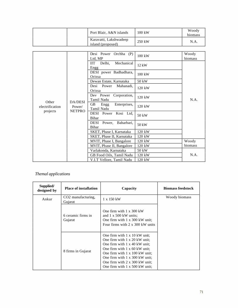
71
Port Blair, A&N islands 100 kW Woody biomass
Karavatti, Lakshwadeep island (proposed)
250 kW N.A.
Desi Power Orchha (P) Ltd, MP
100 kW Woody biomass
IIT Delhi, Mechanical Engg
12 kW
DESI power Badhadhara, Orissa
100 kW
Dewan Estate, Karnataka 50 kW Desi Power Mahanadi, Orissa
120 kW
Dev Power Corporation, Tamil Nadu
120 kW
GB Engg Enterprises, Tamil Nadu
120 kW
DESI Power Kosi Ltd, Bihar
50 kW
DESI Power, Baharbari, Bihar
50 kW
SKET, Phase I, Karnataka 120 kW SKET, Phase II, Karnataka 120 kW
N.A.
MVIT, Phase I, Bangalore 120 kW MVIT, Phase II, Bangalore 120 kW
Woody biomass
Varlakonda, Karnataka 50 kW GB Food Oils, Tamil Nadu 120 kW
Other electrification
projects
DA/DESI Power/
NETPRO
V.I.T Vellore, Tamil Nadu 120 kW N.A.
Themal applications
Supplied/ designed by Place of installation Capacity Biomass feedstock
CO2 manufacturing, Gujarat
1 x 150 kW
6 ceramic firms in Gujarat
One firm with 1 x 300 kW and 1 x 500 kW units; One firm with 1 x 300 kW unit; Four firms with 2 x 300 kW units
Ankur
8 firms in Gujarat
One firm with 1 x 10 kW unit; One firm with 1 x 20 kW unit; One firm with 1 x 40 kW unit; One firm with 1 x 60 kW unit; One firm with 1 x 100 kW unit; One firm with 1 x 300 kW unit; One firm with 2 x 300 kW unit; One firm with 1 x 500 kW unit;
Woody biomass
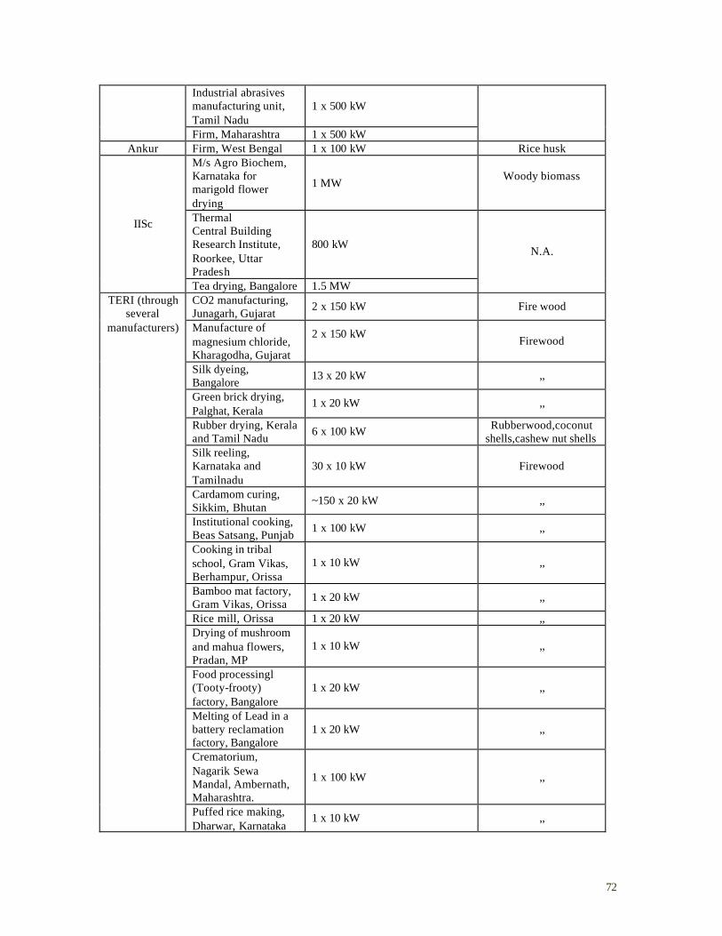
72
Industrial abrasives manufacturing unit, Tamil Nadu
1 x 500 kW
Firm, Maharashtra 1 x 500 kW
Ankur Firm, West Bengal 1 x 100 kW Rice husk M/s Agro Biochem, Karnataka for marigold flower drying
1 MW Woody biomass
Thermal Central Building Research Institute, Roorkee, Uttar Pradesh
800 kW
IISc
Tea drying, Bangalore 1.5 MW
N.A.
CO2 manufacturing, Junagarh, Gujarat
2 x 150 kW Fire wood
Manufacture of magnesium chloride, Kharagodha, Gujarat
2 x 150 kW
Firewood
Silk dyeing, Bangalore
13 x 20 kW ,,
Green brick drying, Palghat, Kerala
1 x 20 kW ,,
Rubber drying, Kerala and Tamil Nadu
6 x 100 kW Rubberwood,coconut shells,cashew nut shells
Silk reeling, Karnataka and Tamilnadu
30 x 10 kW Firewood
Cardamom curing, Sikkim, Bhutan
~150 x 20 kW ,,
Institutional cooking, Beas Satsang, Punjab
1 x 100 kW ,,
Cooking in tribal school, Gram Vikas, Berhampur, Orissa
1 x 10 kW ,,
Bamboo mat factory, Gram Vikas, Orissa
1 x 20 kW ,,
Rice mill, Orissa 1 x 20 kW ,, Drying of mushroom and mahua flowers, Pradan, MP
1 x 10 kW ,,
Food processingl (Tooty-frooty) factory, Bangalore
1 x 20 kW ,,
Melting of Lead in a battery reclamation factory, Bangalore
1 x 20 kW ,,
Crematorium, Nagarik Sewa Mandal, Ambernath, Maharashtra.
1 x 100 kW ,,
TERI (through several
manufacturers)
Puffed rice making, Dharwar, Karnataka
1 x 10 kW ,,
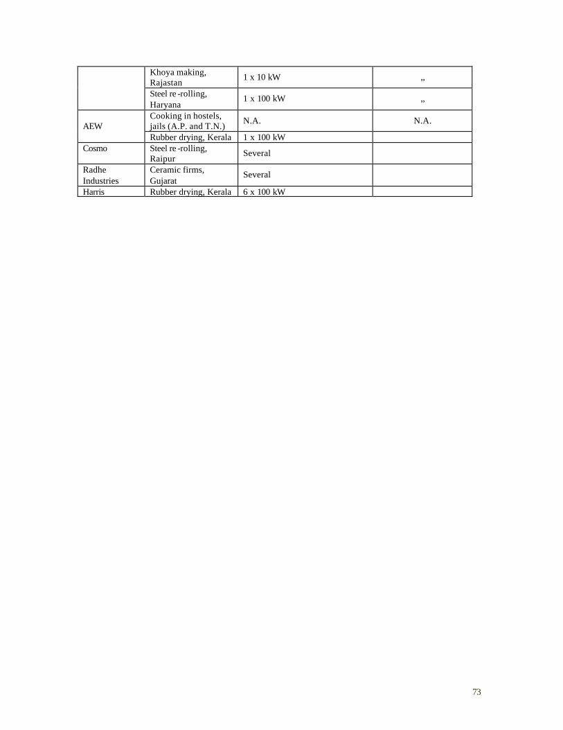
73
Khoya making, Rajastan
1 x 10 kW ,,
Steel re -rolling, Haryana
1 x 100 kW ,,
Cooking in hostels, jails (A.P. and T.N.)
N.A. N.A. AEW
Rubber drying, Kerala 1 x 100 kW Cosmo Steel re -rolling,
Raipur Several
Radhe Industries
Ceramic firms, Gujarat
Several
Harris Rubber drying, Kerala 6 x 100 kW
74
A2.4 Selected Case Studies
A2.4.1 Small and Medium Enterprises
Industrial gas production43
Mahabhadra Industrial Gases, a bottled carbon dioxide (CO2) manufacturing plant located in Gujarat, uses a downdraught gasifier developed by Ankur. The system, with a capacity of 150 kW, has been operating since 1993, and is somewhat unique in that the producer gas is not only used for process heat applications but also serves as a raw material from which CO2 is extracted. The gasifier application has led to improvements in the product quality as the producer gas is a better feedstock for CO2 extraction than the kerosene being used before the installation of the gasifier. The manufacturing unit has completely substituted its kerosene and other liquid-fuel usage with producer gas from the biomass gasifier. Gasifier installation has also led to elimination of sulfur dioxide scrubbing due to which there have been large gains to the owner and the product quality has improved. The total investment cost for the gasifier was Rs. 600,000 and MNES subsidized 20 percent of the cost. Gasifier installation led to increase in production capacity of the system from 80-90 kg of CO2 per hour to 120 kg per hour along with elimination of diesel consumption of 35 liters/hr. The savings in fuel cost alone are estimated to be over 60 percent. With savings in liquid fuel consumption as well as elimination of the scrubbing process and overall improvements in plant productivity, the payback period of the investment was eight months. The owner of the firm does not experience any problems with respect to biomass supply. Wood supply is from a plant named Babool that grows mainly on degraded land. It is delivered to the factory in truckloads at a price of Rs. 1/kg and dried out in the open in the factory premises. The the quality of the dried wood is judged visually – there are no moisture meters for monitoring the wood quality. A person is employed for cutting the wood into specific lengths by a mechanical saw cutter. The gasifier is fed every 2 hours manually from sacks full of wood pieces. At the time of installation, the technology supplier, Ankur, trained the users for a week in the operation and maintenance procedures. The firm owner perceives the gasifier operation to be relatively simple with a low level of skill requirement and he has deployed existing plant personnel for its operation and maintenance. The user-manufacturer linkage is strong and the manufacturer’s participation in major maintenance activities is satisfactory. Regular maintenance requirements are perceived to be low – problems are encountered only if there are interruptions in gasifier operation and in subsequent start-up. Some periodic maintenance is required in repairing the construction material that gets corroded with operation. The owner is considering installing an additional gasifier unit for captive power generation to replace grid power usage in the firm. Steel annealing44
This is a steal annealing plant located in Gujarat that has a gasifier installed for substituting furnace oil usage in its steel-annealing furnace. A 60 kW gasifier was installed in 2002. The design of this gasifier unit is exactly the same as the one installed at Mahabhadra Industrial Gases, except for some minor modifications in the ash disposal system- the unit has a system of continuous ash disposal by a vibrating grate placed at the bottom of the gasifier and the ash is pumped out with the water stream. It is not disposed off into an ash pond. Therefore this method 43 Information based on interviews (see Annexure 4), and web-based information (http://ankurscientific.com). 44 Information based on interviews (see Annexure 4), and web-based information (http://ankurscientific.com).
75
saves on the cost of a water tank construction and also on the space required for a tank installation, reduces water consumption amount and makes the disposal process of ash easier. The additional cost is that of a motor. Burning of the producer gas at the burner attains temperature in the range of 950 to 1000 degrees C, and is sufficient for the annealing operations. There are no supplementary fuel requirements for firing in the furnace. The modified burners, compatible for burning producer gas (burner design modifications are necessary for switching from liquid fuel to producer), were supplied by the gasifier manufacturer, Ankur. The capital cost for the gasifier installation was Rs.3.75 lakhs. Its installation has completely eliminated the furnace oil consumption, and resulted in a 25 percent savings on fuel cost. This translates into an annual savings of Rs.4 lakhs for the user, with a payback period of less than a year. As in the case of the industrial gas manufacturer, the user perceives low skill requirements for operating the gasifier unit. The unit performs well when run continuously, but problems are encountered in starting up the gasifier after shutdown. The gasifier throat needs to be replaced after every six months. For undertaking periodic maintenance activities, the user has a five year Annual Maintenance Contract (AMC) with Ankur. The manufacturer-user linkage seems to be strong – Ankur provides reliable assistance in solving technical problems. There are no problems encountered in wood supply – supply is reliable and the wood is of good quality. The same tree species, Babool is supplied to this firm too. The user is very well ware of biomass gasifier applications for power generation – but is unwilling to go for gasifier application for captive power requirements. He perceives uncertainties with respect to the technology reliability and high system costs. Rubber drying45
The Kerala govt. had given a 5-year subsidized electric supply to promote the rubber industry in the state. During this period, the subsidized cost of electricity was Rs. 0.50/kWh. At the end of this period, the supply price was raised to Rs. 2.5/kWh While the rubber industry protested and went to court to protest against the removal of subsidies, it also realized that it was not in a strong legal position and was therefore looking at other options. Many of them started shifting over to diesel based driers. During a trip to Bangalore, TERI researchers were approached by the owner of one of these rubber firms who had heard of the success of the gasifier applications. This person was interested in looking at gasifier installation possibilities in the rubber industry. After examining the application, TERI felt that an indirect heating system would be best suited for this application. While such a system would be complex and would cost Rs. 3 million, it would have a payback period of 6 months. This firm did not have the resources, though, to install such a system. TERI was subsequently approached by another rubber manufacturer, Bobby Abraham. . He had visited a number of installed units in Bangalore and Gujarat and wanted to get into the business of manufacturing gasifiers. He had an agreement with TERI that involved an upfront fee as well as a royalty. He installed the first gasifier in his own facility and made many additional developments in the process – for example, he developed the process instrumentation for this system. He sold the second system to another crumb rubber manufacturer but that one encountered many technical problems. For example, there was an explosion caused by direct burning of gas without pilot burning of diesel. TERI then designed an external furnace with the 45 Information based on authors’ own knowledge and experiences; TERI’s internal documents and in-house publications.
76
flue gases being then directed into the tunnel. Other modifications were also made. The passage of the high temperature flue gases over long distances corroded the ducts – Bobby moved to a different material to avoid this corrosion. He eventually sold 4 systems through his enterprise Paramount Enviro-energies. All in all, 12 systems have been installed in rubber drying units. Five of these have been installed by a local entrepreneur independently trying to promote gasifiers for rubber industry. This was an updraft design, based on coconut shells, which was a cheap and easily available biomass resource. (Bobby’s design is less polluting than the others’ – that’s a selling point for the former.) TERI also redesigned their gasifiers to run on coconut shells as well as cashew nut shells (although the latter leads to a clinker problem). Additionally, given the high local labor costs, Paramount semi-automated the gasifier feeding as well as the clinker breaking processes. The Rubber Board came into picture at this time and started giving a subsidy of 25% to promote the dissemination of these gasifiers. Ceramic tile manufacture46
Ankur installed its first gasifier in a ceramic tile unit in Gujarat in 2001. Most of the ceramic tile units use liquid fuels like kerosene and furnace oil, and a few advanced units have roller kilns that use LPG. The owner of the unit where the first gasifier was installed was reluctant for fear of not reaching a temperature level sufficient for his operations (1050-1100 °C). The furnace consumed 1500 litres of kerosene daily and a kerosene replacement of only 50 to 70 percent was planned in the initial stages. Gasifier installation led to a 90 percent reduction in the kerosene consumption. Fuel supply is from Prosopis Juliflora, a sturdy species that is found in saline/arid areas. Its growth is highly prolific and encroaches upon agricultural lands. Therefore the government of Gujarat announced a policy a couple of years ago for harvesting this species and containing its growth. This has reduced prices from Rs. 1000 per ton to Rs. 500 to 600 per ton and the biomass is readily delivered to the ceramic units. For a representative ceramic tile unit, a gasifier capacity of 300 kWe requires an investment of Rs. 3 million. Kerosene consumption before gasifier installation is estimated to be 3,800 liters/day and the reduction in consumption after gasifier installation is 3,400 liters/day. The daily wood consumption is around 13,000 kg. This results in a payback period of 4 to 5 months for the unit. At present, there are fifteen applications in a cluster of ceramic manufacturing units in Gujarat, and many of these have crossed 10,000 hours of operation. Based on these encouraging results, two other firms installed gasifiers in biscuit making and glazing furnaces- each gasifier resulted in a saving of 1300-1500 liters per day of kerosene by substituting it with a wood consumption of 6 MT per day (250 kg/hr/day of biomass consumption). The daily monetary savings were estimated to be above Rs. 14,000 per gasifier and has enhanced competitiveness of these firms.
46 Information based on interviews (see in Annexure 4), internal documents of Ankur, and web-based information (http://ankurscientific.com).
77
A2.4.2 Informal Enterprises
Silk reeling gasifiers 47
The implementation of gasifiers in silk reeling enterprises had its genesis in a World Bank (WB)-led project to aid the sericulture industry. The improved silk reeling ovens being used in the initial stages of the project were not performing well and TERI was initially invited to do an energy audit of these ovens. This work eventually led TERI to suggest the use of gasifiers for this application. Using its own funds, TERI made a rough working design of a gasifier-based silk reeling oven in its workshop at Gualpahari. The Swiss Development Cooperation (SDC) funded a trial of this gasifier that was carried out in Hindupur. The system was based on a 10kg/hr. gasifier, with improvements being made during testing. The trial demonstrated that a gasifier-based system could be used for silk reeling with 50% savings in firewood consumption. This system also resulted in productivity improvement – the silk production increased by about 2% (which was substantial in financial terms, given the low margins in silk reeling). In addition, the quality of the silk produced also improved. The improvements in silk production as well quality were both unanticipated benefits. An additional unanticipated benefit was the savings in water consumption, which had financial implications since the silk reelers buy the water needed for their processing. Additionally, environmental benefits included an elimination of smoke and generally cleaner surroundings. The further evolution of this prototype into an industrial prototype involved, beyond numerous inputs from users, a number of actors including a SDC consultant, various research labs, the Industrial Design Center at IITB (for overall design improvements), and Kvaerner Power Gas (who provided technical inputs as well as suggestions for vendor development). Two systems were subsequently placed with silk reelers in a dense cluster and testing was then carried out for two years. At the end of the study in late 1997 or so, it was found that the silk yield was increased by 3% (partly because of an innovation in the bath design). The entire sericulture system was patented as a package. Despite the promise of these gasifie rs-based systems, and the advantages offered by them, dissemination was hampered by a number of reasons including the reluctance of many of the users (including government agencies) to pay for them and by the disinterest in large financing agencies in projects of such a small scale individually. Silk reelers were also considered high-risk because of having defaulted on loans in the past. Although some systems were disseminated eventually under a subsidy scheme implemented by the SDC SERI-2000 program, the scale of this dissemination was well below the potential. Cardamom drying48
TERI was first involved in cardamom drying back in 1987. It carried out a project funded by the DST to improve the efficiency of the cardamom drying process in Kerala. This was a 2-year project in an experimental plant of the Cardamom Planter’s Association. The efficiency of the traditional drying process was 3% – converting this to a furnace coupled to a compact heat
47 Information based on authors’ own knowledge and experiences, interviews (see Annexure 4), information complied from TERI publications; Dhingra & Kishore, 1999. 48 Information based on authors’ own knowledge and experiences, interviews (see Annexure 4), information complied from TERI publications; Mande et. al. 1999.
78
exchanger resulted in fuel savings of 55-65% as well as reduced drying times while retaining the quality of the product. In 1995, soon after TERI’s sericulture work started, it was approached by SDC in connection with the Indo-Swiss Project Sikkim (ISPS) project. This project was mainly focused on horticulture (the Sikkim Dept. of Horticulture was ISPS’s partner on this effort). The state is a major producer of cardamom where the production is dominated by small farmers with 2-3 acres of land who dry their cardamom in individual small bhattis (ovens) – there are about 60,000 bhattis in Sikkim. The gasifier design had to consider the following constraints:
• No power was available; therefore no blower would be available, unlike the design used in the sericulture project;
• All the components had to be transportable on human backs since that was the only mode of transport available; and
• ISPS also wanted to the gasifier to be cheap and wanted it to be made locally. During laboratory experimentation, TERI came up with a ‘natural draft’ gasifier that was initially derived from a tandoor. The design was modified to allow recharging during use, and it required recharging every 4 hours. Since operators were reluctant to carry out this task in the middle of the night, a further modification was carried out to increase the recharging time to every 8 hours. The design was also based on a simple oil drum with a ceramic ring, both of which could be carried on human backs and assembled locally. The final cost of the system was Rs. 10,000. Not only did it result in fuel savings, the cardamom itself was of higher quality – the pods retained their reddish color and their oil content was also 35% higher and of better quality than the traditionally dried pods. The first 10-15 systems were installed free of charge as demonstration units by ISPS. After that, the Horticulture Department decided to subsidize (with ISPS funding) a limited dissemination of these gasifier-based systems whereby the farmers would have to pay only 20% of the costs. About 50-60 systems were disseminated under this program, although without any well-defined process to select recipients. The Dept. of Horticulture eventually took over the program and provided a 50% subsidy that was eventually utilized for the dissemination of some 100 more gasifiers.
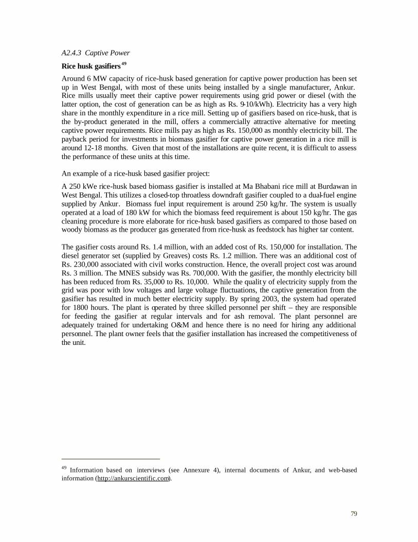
79
A2.4.3 Captive Power
Rice husk gasifiers 49
Around 6 MW capacity of rice-husk based generation for captive power production has been set up in West Bengal, with most of these units being installed by a single manufacturer, Ankur. Rice mills usually meet their captive power requirements using grid power or diesel (with the latter option, the cost of generation can be as high as Rs. 9-10/kWh). Electricity has a very high share in the monthly expenditure in a rice mill. Setting up of gasifiers based on rice-husk, that is the by-product generated in the mill, offers a commercially attractive alternative for meeting captive power requirements. Rice mills pay as high as Rs. 150,000 as monthly electricity bill. The payback period for investments in biomass gasifier for captive power generation in a rice mill is around 12-18 months. Given that most of the installations are quite recent, it is difficult to assess the performance of these units at this time. An example of a rice-husk based gasifier project:
A 250 kWe rice-husk based biomass gasifier is installed at Ma Bhabani rice mill at Burdawan in West Bengal. This utilizes a closed-top throatless downdraft gasifier coupled to a dual-fuel engine supplied by Ankur. Biomass fuel input requirement is around 250 kg/hr. The system is usually operated at a load of 180 kW for which the biomass feed requirement is about 150 kg/hr. The gas cleaning procedure is more elaborate for rice-husk based gasifiers as compared to those based on woody biomass as the producer gas generated from rice-husk as feedstock has higher tar content. The gasifier costs around Rs. 1.4 million, with an added cost of Rs. 150,000 for installation. The diesel generator set (supplied by Greaves) costs Rs. 1.2 million. There was an additional cost of Rs. 230,000 associated with civil works construction. Hence, the overall project cost was around Rs. 3 million. The MNES subsidy was Rs. 700,000. With the gasifier, the monthly electricity bill has been reduced from Rs. 35,000 to Rs. 10,000. While the qualit y of electricity supply from the grid was poor with low voltages and large voltage fluctuations, the captive generation from the gasifier has resulted in much better electricity supply. By spring 2003, the system had operated for 1800 hours. The plant is operated by three skilled personnel per shift – they are responsible for feeding the gasifier at regular intervals and for ash removal. The plant personnel are adequately trained for undertaking O&M and hence there is no need for hiring any additional personnel. The plant owner feels that the gasifier installation has increased the competitiveness of the unit.
49 Information based on interviews (see Annexure 4), internal documents of Ankur, and web-based information (http://ankurscientific.com).

80
A2.4.4 Rural areas – remote villages
Hosahalli and Hanumanthanagara experiences in village electrification50
Hosahalli and Hanumanthanagara are villages in Tumkur district in Karnataka that utilize electricity generated by 20 kW woody-biomass based gasifier systems connected to a diesel engine generation system. The electricity provides lighting, water supply for domestic use and flourmill operation. Hoshahalli has 35 households with a population of 218 and Hanumanthanagara has 58 households with a population of 319. The former village was non-electrified while the latter had only 43 percent electrified households before the installation of the gasifiers. Both projects were executed by ASTRA (Centre for Application of Science and Technology for Rural Areas), IISc and use gasifiers designed by IISc. The project at Hoshahalli (which was the first rural electrification demonstration project in the country) was started in 1988 and implemented in five phases – raising energy forest for wood supply and installing a wood gasifier-diesel generator plant; providing electricity for lighting to all households; pumping drinking water; installing a flour mill and pumping water for irrigation. It took about a year to stabilize the first two phases and the fourth and fifth phases were implemented in the fifth year. The Hosahalli system is reported to have operated for 96 percent and 94 percent of the days during 1998 and 1999, respectively while in Hanumanthanagara, the system is reported to have operated for 86 percent and 90 percent of the days during the same period. Non-availability of operators, diesel, and occurrence of some social problems resulted in non-operation on the remaining days. Though the system was operated for most of the days, the load on the system was very low leading to a capacity utilization of 7 percent in Hosahalli and 3 percent in Hanumanthanagara (though there were some attempts to increase the load by setting up of irrigation-pumping activities based on the gasifier). The systems operated in dual-fuel mode for around 70 to 75 percent of the operating days. The plants were run in diesel-only mode due to shortages in dried, chopped and sized wood that were caused by non-availability of labor for cutting wood or due to rain preventing drying of wood. Measures to overcome these problems included using a mechanical wood chipper to give better fuel quality, and drying of wood using exhaust heat from engines. Also, a maintenance contract was given to an entrepreneur. The approach adopted in the villages was not to sell electricity used, but to charge for the services provided. The rates for the services were fixed in consultation with village community. For lighting, the rate was Rs.5/bulb-point/month (for a 40W fluorescent light tube for 4 hrs./day requiring about 5 kWh/month). Water supply from private taps was charged at Rs.10/month/household and milling of grain was charged at Rs. 0.5 to 0.8/kg of grain. While initially low tariffs were fixed in consultation with the village community, they were raised at later stages of project implementation following growth in income-generating activities with the setting up of irrigation water supply and non-agro based activities. The recovery of fee-for-service in these villages ranged between 52 to 76 percent during 1998 and 1999, during the time the study was conducted.
50 Sources: Someshekhar et. al., 2000; Srinivas et. al., 1992.
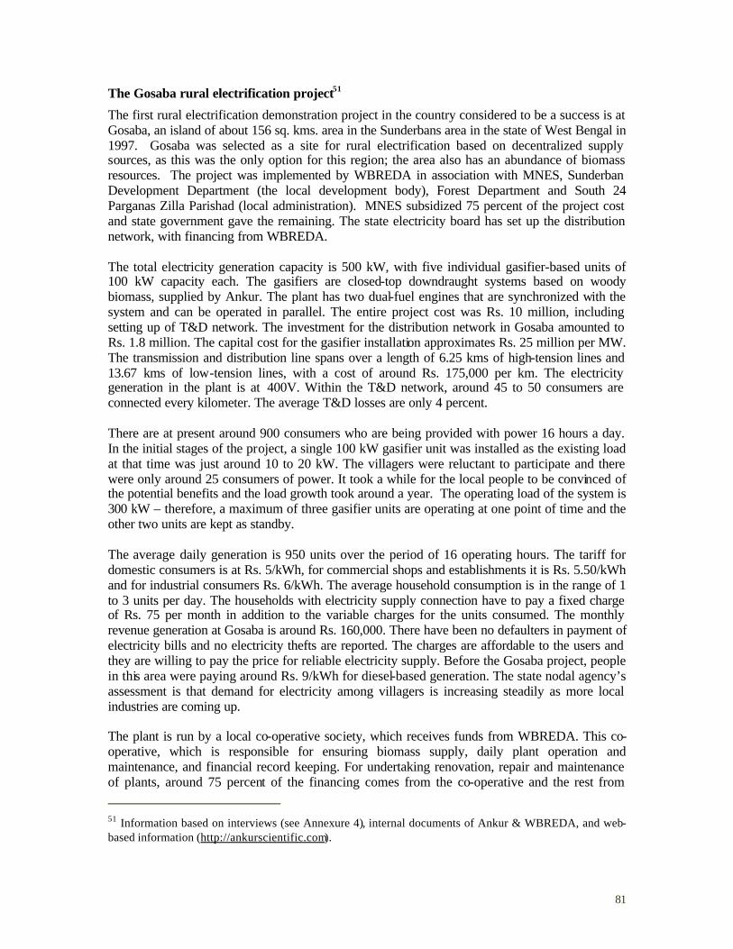
81
The Gosaba rural electrification project51
The first rural electrification demonstration project in the country considered to be a success is at Gosaba, an island of about 156 sq. kms. area in the Sunderbans area in the state of West Bengal in 1997. Gosaba was selected as a site for rural electrification based on decentralized supply sources, as this was the only option for this region; the area also has an abundance of biomass resources. The project was implemented by WBREDA in association with MNES, Sunderban Development Department (the local development body), Forest Department and South 24 Parganas Zilla Parishad (local administration). MNES subsidized 75 percent of the project cost and state government gave the remaining. The state electricity board has set up the distribution network, with financing from WBREDA. The total electricity generation capacity is 500 kW, with five individual gasifier-based units of 100 kW capacity each. The gasifiers are closed-top downdraught systems based on woody biomass, supplied by Ankur. The plant has two dual-fuel engines that are synchronized with the system and can be operated in parallel. The entire project cost was Rs. 10 million, including setting up of T&D network. The investment for the distribution network in Gosaba amounted to Rs. 1.8 million. The capital cost for the gasifier installation approximates Rs. 25 million per MW. The transmission and distribution line spans over a length of 6.25 kms of high-tension lines and 13.67 kms of low-tension lines, with a cost of around Rs. 175,000 per km. The electricity generation in the plant is at 400V. Within the T&D network, around 45 to 50 consumers are connected every kilometer. The average T&D losses are only 4 percent. There are at present around 900 consumers who are being provided with power 16 hours a day. In the initial stages of the project, a single 100 kW gasifier unit was installed as the existing load at that time was just around 10 to 20 kW. The villagers were reluctant to participate and there were only around 25 consumers of power. It took a while for the local people to be convinced of the potential benefits and the load growth took around a year. The operating load of the system is 300 kW – therefore, a maximum of three gasifier units are operating at one point of time and the other two units are kept as standby. The average daily generation is 950 units over the period of 16 operating hours. The tariff for domestic consumers is at Rs. 5/kWh, for commercial shops and establishments it is Rs. 5.50/kWh and for industrial consumers Rs. 6/kWh. The average household consumption is in the range of 1 to 3 units per day. The households with electricity supply connection have to pay a fixed charge of Rs. 75 per month in addition to the variable charges for the units consumed. The monthly revenue generation at Gosaba is around Rs. 160,000. There have been no defaulters in payment of electricity bills and no electricity thefts are reported. The charges are affordable to the users and they are willing to pay the price for reliable electricity supply. Before the Gosaba project, people in this area were paying around Rs. 9/kWh for diesel-based generation. The state nodal agency’s assessment is that demand for electricity among villagers is increasing steadily as more local industries are coming up. The plant is run by a local co-operative society, which receives funds from WBREDA. This co-operative, which is responsible for ensuring biomass supply, daily plant operation and maintenance, and financial record keeping. For undertaking renovation, repair and maintenance of plants, around 75 percent of the financing comes from the co-operative and the rest from
51 Information based on interviews (see Annexure 4), internal documents of Ankur & WBREDA, and web-based information (http://ankurscientific.com).

82
MNES. The success in running this rural energy co-operative is partly attributed to the history of success in co-operative movements in that area. Ankur undertook turnkey operation for the project and at present intervenes in major maintenance and retrofitting functions. It has trained local people in plant operation and maintenance. It also periodically reviews plant operation. One of its service engineers based in eastern India supervises these activities. The state nodal agency, WBREDA, functions as the Technical Backup Unit for the project. It provides both technical and non-technical support for running the system, monitors the operation of the plant and performance of the plant personnel. It periodically conducts tests for the plant operators to monitor their performance.

83
A2.4.5 Rural areas – grid-interfaced generation
Biomass Energy for Rural India (BERI)52
Biomass Energy for Rural India (BERI) is a $8.6 million UNDP/GEF project with co-financing from ICEF USA, and state and central governments in India.53 The five-year project which started in mid-2001 is based on the research, development, and small-scale demonstrations over the past 10 to 15 years in Hosahalli and Hanumanthanagara villages. The executing agency for the project is the Department of Rural Development, Government of Karnataka while the implementing agency is the Karnataka State Council of Science and Technology (KSCST), Bangalore. The UNDP/GEF, ICEF, and the Government of Karnataka (GoK) are providing financial resources for the project while the MNES is providing national support for policy, planning and financial incentives towards investment cost for biomass gasifier power generation system and community biogas electricity system. GoK will also provide overall administrative as well as logistics support to the project. BERI aims to reduce CO2 emissions through the promotion of bioenergy as a viable and sustainable option to meet the rural energy service needs in India. One of the objectives of the full project is to demonstrate the commercial viability of the concept of bioenergy systems. The project ultimately aims to provide decentralized bioenergy technology in the form of rural energy services for lighting, drinking water supply, cooking gas, irrigation water supply, and milling. It also intends to help in removing key barriers to large-scale adoption and commercialization of bioenergy technology packages. Two important features of the project are replicability and sustainability. The project will be implemented mainly in a cluster of about 24 villages of Tumkur district in Karnataka. The benefits are targeted to reach some 25,000 families or around 15,000 people in the five taluks of Tumkur, among them marginal farmers and rural entrepreneurs such as biogas operators, flour mill operators, mulberry and silkworm rearers. The project targets setting up of 1.2 MW of total woody biomass gasifier based system with a generating potential of 4,800 MWh of bioelectricity annually. A gasifier-system based on 100% producer gas will be demonstrated. A dual-fuel system too will be set up, but this seems to be financially unviable due to the high cost of diesel. Community biogas plants will be set up for meeting cooking energy requirements. Power supply will be through the existing distribution network and the extra power will be fed into the grid at a price of Rs.3.32/kWh.54 The recovery from selling power to the grid will be a key determinant of the project’s financial sustainability. BERI will obtain its biomass supplies from two sources: dedicated energy plantations and supply from existing market. For the latter, it intends to set up 400-500 ha of short rotation forest plantations, 300-400 ha of agro-forestry systems, 200-300 ha of community forestry, 400-500 ha of orchards and 100-125 ha of high input forestry. These will be planted on wastelands, private lands, and government and common land.
52 Information based on interviews (see Annexure 4), project documents, and web-based information (www.undp.org.) 53 The project comes under the GEF Operational Program 6: “promoting the adoption of renewable energy by removing barriers and reducing implementation costs”. 54 This tariff is fixed by MNES.
84
BERI also proposes to set up a 'Bioenergy Services Enterprises' as a rural energy service company (RESCO). The project is based on the ‘fee-for-service’ concept – the pricing will be on the basis of energy services provided and not for electricity units consumed. By the end of the project period, the goal is to ensure that the fee-for-energy service approach will be able to recover all costs of the bioenergy systems. Linkages will be made with micro-credit organizations, NGOs and other village level money lending groups for enabling cost recovery. Two models have been proposed to ensure financial sustainability of the project after project completion. These are:
• Commercial bank – entrepreneur system: Under this system all the project assets and components will be transferred to a commercial bank. The bank will identify entrepreneurs and provide working capital and the entrepreneurs in turn will repay the bank from the revenue collected from the beneficiaries. The profits or the surplus income earned by the bank will be converted into a ‘special fund’ to provide start-up capital to entrepreneurs to set-up bioenergy systems in new villages.
• Panchayat (local government) – entrepreneurs/NGO system: Here all project assets will be transferred to the Panchayats, in consultation with the Zilla Parishad (District Administration). The Zilla Parishad will provide the financial guarantee to the Panchayats who in turn will take responsibility for the project. The Panchayats will in turn identify NGOs or entrepreneurs and contract out the operation, maintenance and management of the bioenergy system for an agreed technical fee. The Panchayats will own the assets. The identified NGO or entrepreneur will transfer the surplus income to the Panchayats. The surplus income will be converted into a ‘special fund’ to provide start-up capital for initiating bioenergy project in other villages.
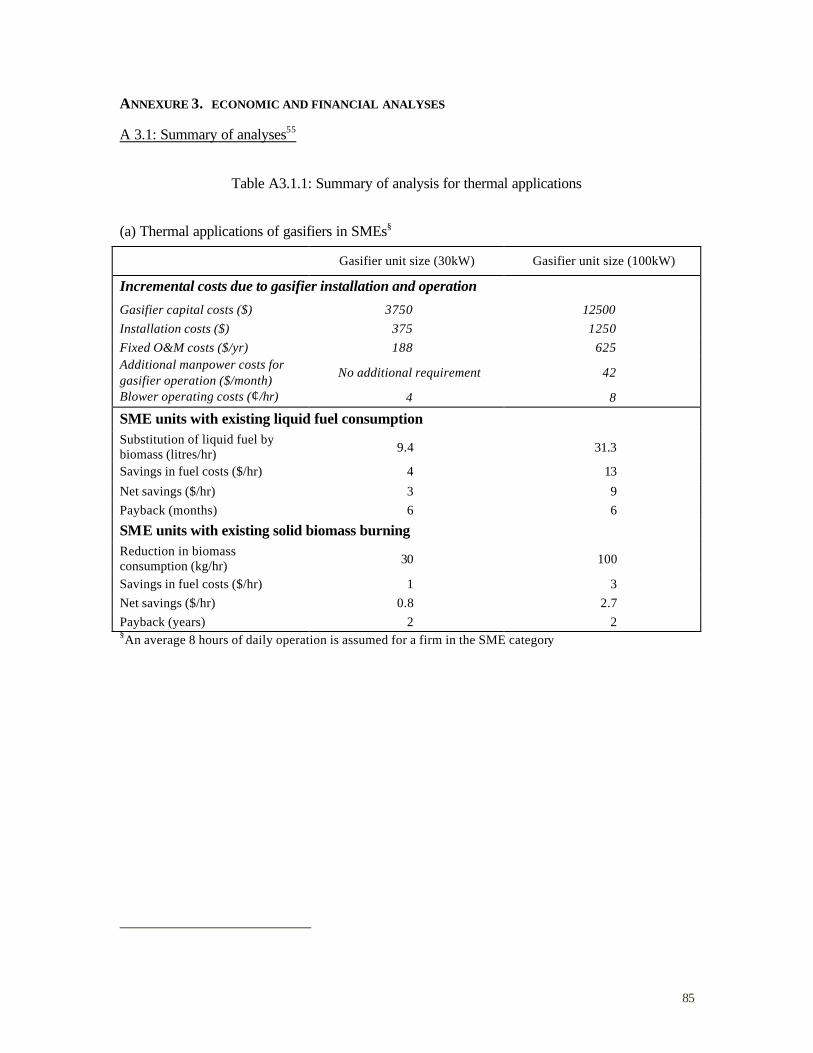
85
ANNEXURE 3. ECONOMIC AND FINANCIAL ANALYSES
A 3.1: Summary of analyses55
Table A3.1.1: Summary of analysis for thermal applications
(a) Thermal applications of gasifiers in SMEs§
Gasifier unit size (30kW) Gasifier unit size (100kW)
Incremental costs due to gasifier installation and operation
Gasifier capital costs ($) 3750 12500 Installation costs ($) 375 1250 Fixed O&M costs ($/yr) 188 625 Additional manpower costs for gasifier operation ($/month)
No additional requirement 42
Blower operating costs (¢/hr) 4 8
SME units with existing liquid fuel consumption Substitution of liquid fuel by biomass (litres/hr) 9.4 31.3
Savings in fuel costs ($/hr) 4 13
Net savings ($/hr) 3 9 Payback (months) 6 6
SME units with existing solid biomass burning Reduction in biomass consumption (kg/hr) 30 100
Savings in fuel costs ($/hr) 1 3 Net savings ($/hr) 0.8 2.7 Payback (years) 2 2 §An average 8 hours of daily operation is assumed for a firm in the SME category
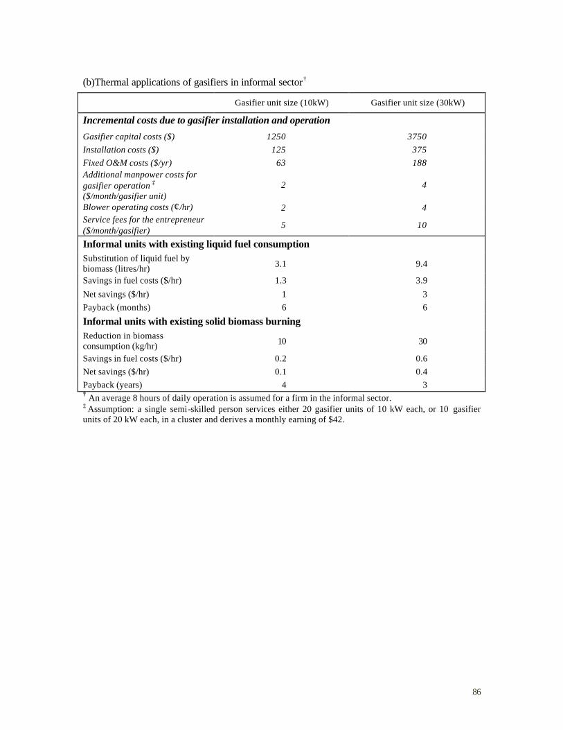
86
(b)Thermal applications of gasifiers in informal sector†
Gasifier unit size (10kW) Gasifier unit size (30kW)
Incremental costs due to gasifier installation and operation
Gasifier capital costs ($) 1250 3750 Installation costs ($) 125 375 Fixed O&M costs ($/yr) 63 188 Additional manpower costs for gasifier operation ‡ ($/month/gasifier unit)
2 4
Blower operating costs (¢/hr) 2 4 Service fees for the entrepreneur ($/month/gasifier)
5 10
Informal units with existing liquid fuel consumption Substitution of liquid fuel by biomass (litres/hr) 3.1 9.4
Savings in fuel costs ($/hr) 1.3 3.9
Net savings ($/hr) 1 3 Payback (months) 6 6
Informal units with existing solid biomass burning Reduction in biomass consumption (kg/hr) 10 30
Savings in fuel costs ($/hr) 0.2 0.6 Net savings ($/hr) 0.1 0.4 Payback (years) 4 3 † An average 8 hours of daily operation is assumed for a firm in the informal sector. ‡ Assumption: a single semi-skilled person services either 20 gasifier units of 10 kW each, or 10 gasifier units of 20 kW each, in a cluster and derives a monthly earning of $42.
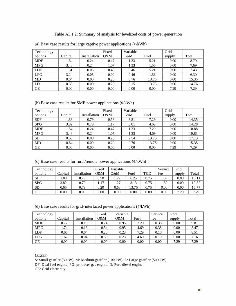
87
Table A3.1.2: Summary of analysis for levelized costs of power generation
(a) Base case results for large captive power applications (¢/kWh)
Technology options Capital Installation
Fixed O&M
Variable O&M Fuel
Grid supply Total
MDF 1.54 0.24 0.47 1.33 5.21 0.00 8.79 MPG 3.48 0.24 1.07 1.33 1.56 0.00 7.69 LDF 1.31 0.05 0.40 0.46 5.21 0.00 7.43 LPG 3.24 0.05 0.99 0.46 1.56 0.00 6.30 MD 0.64 0.00 0.20 0.76 13.75 0.00 15.35 LD 0.66 0.00 0.20 0.15 13.75 0.00 14.76 GE 0.00 0.00 0.00 0.00 0.00 7.29 7.29 (b) Base case results for SME power applications (¢/kWh)
Technology options Capital Installation
Fixed O&M
Variable O&M Fuel
Grid supply Total
SDF 1.88 0.79 0.58 3.81 7.29 0.00 14.35 SPG 3.82 0.79 1.17 3.81 4.69 0.00 14.28 MDF 1.54 0.24 0.47 1.33 7.29 0.00 10.88 MPG 3.48 0.24 1.07 1.33 4.69 0.00 10.81 SD 0.65 0.00 0.20 2.54 13.75 0.00 17.13 MD 0.64 0.00 0.20 0.76 13.75 0.00 15.35 GE 0.00 0.00 0.00 0.00 0.00 7.29 7.29 (c) Base case results for rural/remote power applications (¢/kWh)
Technology options Capital Installation
Fixed O&M
Variable O&M Fuel T&D
Service fee
Grid supply Total
SDF 1.88 0.79 0.58 1.27 6.25 0.75 1.59 0.00 13.11 SPG 3.82 0.79 1.17 1.27 3.13 0.75 1.59 0.00 12.52 SD 0.65 0.79 0.20 0.63 13.75 0.75 0.00 0.00 16.77 GE 0.00 0.00 0.00 0.00 0.00 0.00 0.00 7.29 7.29 (d) Base case results for grid-interfaced power applications (¢/kWh)
Technology options Capital Installation
Fixed O&M
Variable O&M Fuel
Service fee
Grid supply Total
MDF 0.77 0.18 0.24 0.95 7.29 0.38 0.00 9.81 MPG 1.74 0.18 0.54 0.95 4.69 0.38 0.00 8.47 LDF 0.66 0.04 0.20 0.23 7.29 0.10 0.00 8.51 LPG 1.62 0.04 0.50 0.23 4.69 0.10 0.00 7.16 GE 0.00 0.00 0.00 0.00 0.00 0.00 7.29 7.29 LEGEND: S: Small gasifier (30kW); M: Medium gasifier (100 kW); L: Large gasifier (500 kW) DF: Dual fuel engine; PG: producer gas engine; D: Pure diesel engine GE: Grid electricity
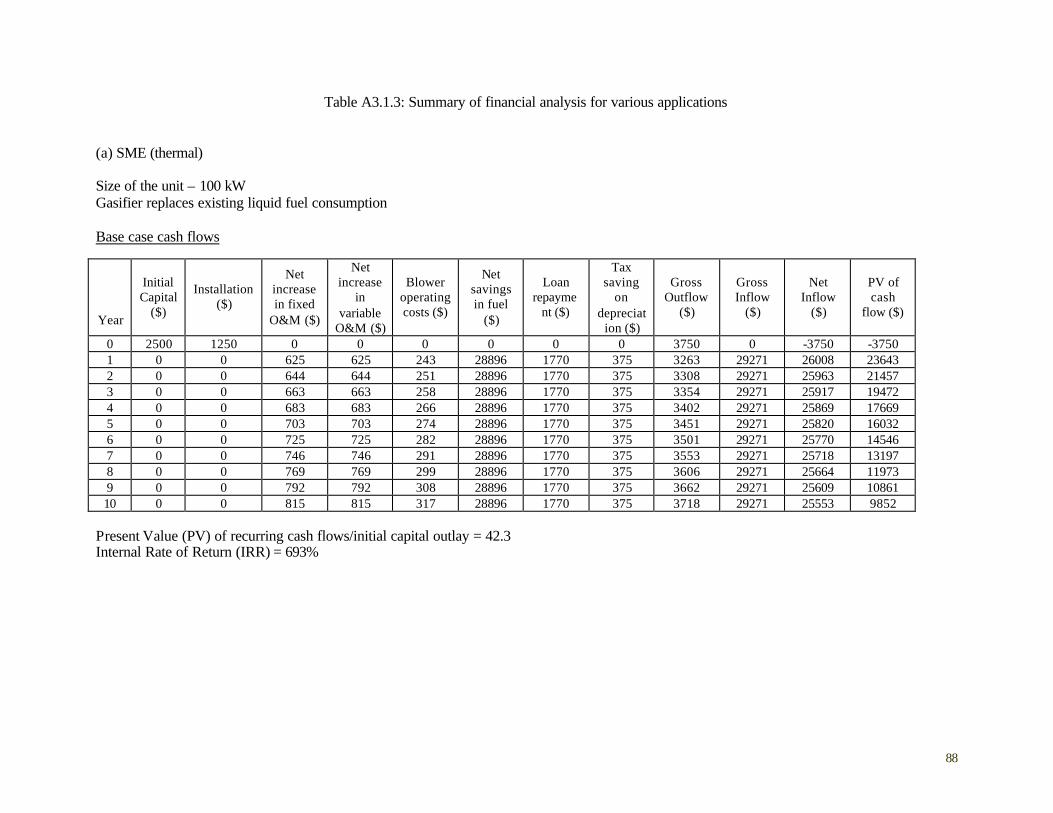
88
Table A3.1.3: Summary of financial analysis for various applications (a) SME (thermal) Size of the unit – 100 kW Gasifier replaces existing liquid fuel consumption Base case cash flows
Year
Initial Capital
($)
Installation ($)
Net increase in fixed
O&M ($)
Net increase
in variable
O&M ($)
Blower operating costs ($)
Net savings in fuel
($)
Loan repayme
nt ($)
Tax saving
on depreciat
ion ($)
Gross Outflow
($)
Gross Inflow
($)
Net Inflow
($)
PV of cash
flow ($)
0 2500 1250 0 0 0 0 0 0 3750 0 -3750 -3750 1 0 0 625 625 243 28896 1770 375 3263 29271 26008 23643 2 0 0 644 644 251 28896 1770 375 3308 29271 25963 21457 3 0 0 663 663 258 28896 1770 375 3354 29271 25917 19472 4 0 0 683 683 266 28896 1770 375 3402 29271 25869 17669 5 0 0 703 703 274 28896 1770 375 3451 29271 25820 16032 6 0 0 725 725 282 28896 1770 375 3501 29271 25770 14546 7 0 0 746 746 291 28896 1770 375 3553 29271 25718 13197 8 0 0 769 769 299 28896 1770 375 3606 29271 25664 11973 9 0 0 792 792 308 28896 1770 375 3662 29271 25609 10861 10 0 0 815 815 317 28896 1770 375 3718 29271 25553 9852
Present Value (PV) of recurring cash flows/initial capital outlay = 42.3 Internal Rate of Return (IRR) = 693%
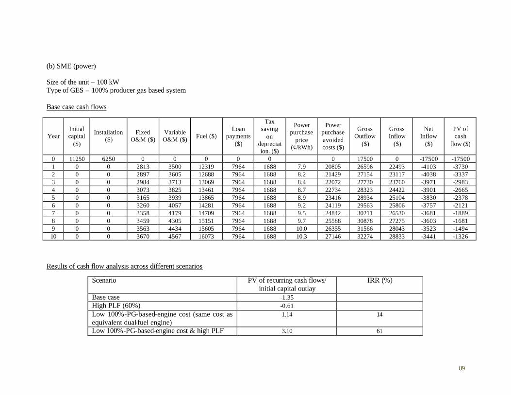
89
(b) SME (power) Size of the unit – 100 kW Type of GES – 100% producer gas based system Base case cash flows
Year Initial capital
($)
Installation ($)
Fixed O&M ($)
Variable O&M ($) Fuel ($)
Loan payments
($)
Tax saving
on depreciation. ($)
Power purchase
price (¢/kWh)
Power purchase avoided costs ($)
Gross Outflow
($)
Gross Inflow
($)
Net Inflow
($)
PV of cash
flow ($)
0 11250 6250 0 0 0 0 0 0 17500 0 -17500 -17500 1 0 0 2813 3500 12319 7964 1688 7.9 20805 26596 22493 -4103 -3730 2 0 0 2897 3605 12688 7964 1688 8.2 21429 27154 23117 -4038 -3337 3 0 0 2984 3713 13069 7964 1688 8.4 22072 27730 23760 -3971 -2983 4 0 0 3073 3825 13461 7964 1688 8.7 22734 28323 24422 -3901 -2665 5 0 0 3165 3939 13865 7964 1688 8.9 23416 28934 25104 -3830 -2378 6 0 0 3260 4057 14281 7964 1688 9.2 24119 29563 25806 -3757 -2121 7 0 0 3358 4179 14709 7964 1688 9.5 24842 30211 26530 -3681 -1889 8 0 0 3459 4305 15151 7964 1688 9.7 25588 30878 27275 -3603 -1681 9 0 0 3563 4434 15605 7964 1688 10.0 26355 31566 28043 -3523 -1494 10 0 0 3670 4567 16073 7964 1688 10.3 27146 32274 28833 -3441 -1326
Results of cash flow analysis across different scenarios
Scenario PV of recurring cash flows/ initial capital outlay
IRR (%)
Base case -1.35 High PLF (60%) -0.61 Low 100%-PG-based-engine cost (same cost as equivalent dual-fuel engine)
1.14 14
Low 100%-PG-based-engine cost & high PLF 3.10 61
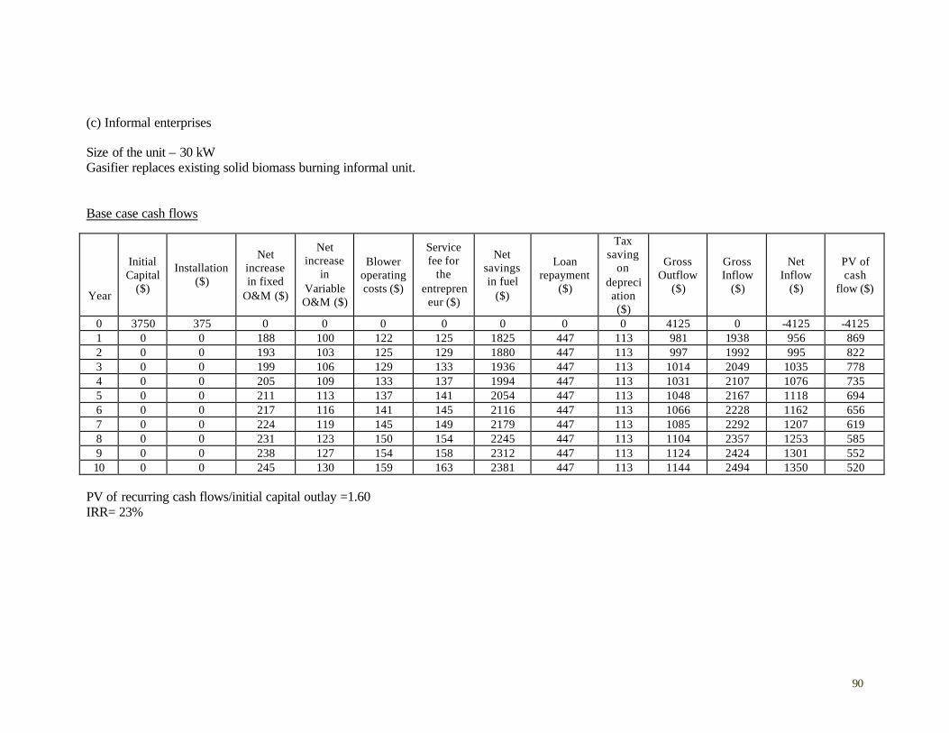
90
(c) Informal enterprises Size of the unit – 30 kW Gasifier replaces existing solid biomass burning informal unit. Base case cash flows
Year
Initial Capital
($)
Installation ($)
Net increase in fixed
O&M ($)
Net increase
in Variable O&M ($)
Blower operating costs ($)
Service fee for
the entrepren
eur ($)
Net savings in fuel
($)
Loan repayment
($)
Tax saving
on depreciation ($)
Gross Outflow
($)
Gross Inflow
($)
Net Inflow
($)
PV of cash
flow ($)
0 3750 375 0 0 0 0 0 0 0 4125 0 -4125 -4125 1 0 0 188 100 122 125 1825 447 113 981 1938 956 869 2 0 0 193 103 125 129 1880 447 113 997 1992 995 822 3 0 0 199 106 129 133 1936 447 113 1014 2049 1035 778 4 0 0 205 109 133 137 1994 447 113 1031 2107 1076 735 5 0 0 211 113 137 141 2054 447 113 1048 2167 1118 694 6 0 0 217 116 141 145 2116 447 113 1066 2228 1162 656 7 0 0 224 119 145 149 2179 447 113 1085 2292 1207 619 8 0 0 231 123 150 154 2245 447 113 1104 2357 1253 585 9 0 0 238 127 154 158 2312 447 113 1124 2424 1301 552 10 0 0 245 130 159 163 2381 447 113 1144 2494 1350 520
PV of recurring cash flows/initial capital outlay =1.60 IRR= 23%
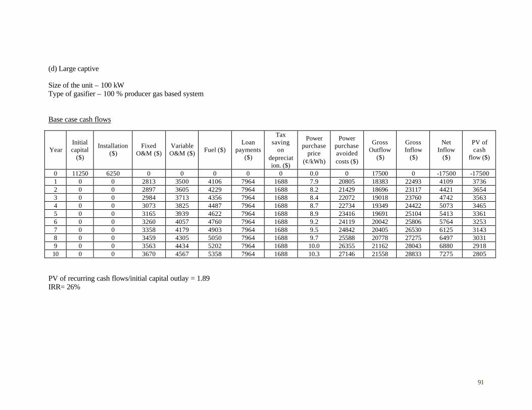
91
(d) Large captive Size of the unit – 100 kW Type of gasifier – 100 % producer gas based system Base case cash flows
Year Initial capital
($)
Installation ($)
Fixed O&M ($)
Variable O&M ($) Fuel ($)
Loan payments
($)
Tax saving
on depreciation. ($)
Power purchase
price (¢/kWh)
Power purchase avoided costs ($)
Gross Outflow
($)
Gross Inflow
($)
Net Inflow
($)
PV of cash
flow ($)
0 11250 6250 0 0 0 0 0 0.0 0 17500 0 -17500 -17500 1 0 0 2813 3500 4106 7964 1688 7.9 20805 18383 22493 4109 3736 2 0 0 2897 3605 4229 7964 1688 8.2 21429 18696 23117 4421 3654 3 0 0 2984 3713 4356 7964 1688 8.4 22072 19018 23760 4742 3563 4 0 0 3073 3825 4487 7964 1688 8.7 22734 19349 24422 5073 3465 5 0 0 3165 3939 4622 7964 1688 8.9 23416 19691 25104 5413 3361 6 0 0 3260 4057 4760 7964 1688 9.2 24119 20042 25806 5764 3253 7 0 0 3358 4179 4903 7964 1688 9.5 24842 20405 26530 6125 3143 8 0 0 3459 4305 5050 7964 1688 9.7 25588 20778 27275 6497 3031 9 0 0 3563 4434 5202 7964 1688 10.0 26355 21162 28043 6880 2918 10 0 0 3670 4567 5358 7964 1688 10.3 27146 21558 28833 7275 2805
PV of recurring cash flows/initial capital outlay = 1.89 IRR= 26%
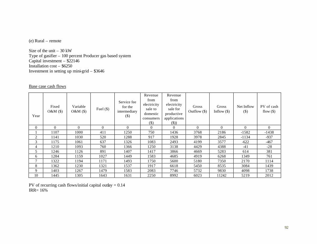
92
(e) Rural – remote Size of the unit – 30 kW Type of gasifier – 100 percent Producer gas based system Capital investment – $22146 Installation cost – $6250 Investment in setting up mini-grid – $3646 Base case cash flows
Year
Fixed O&M ($)
Variable O&M ($)
Fuel ($)
Service fee for the
intermediary($)
Revenue from
electricity sale to
domestic consumers
($)
Revenue from
electricity sale for
productive applications
($))
Gross Outflow ($)
Gross Inflow ($)
Net Inflow ($)
PV of cash flow ($)
0 0 0 0 0 0 0 0 0 0 0 1 1107 1000 411 1250 750 1436 3768 2186 -1582 -1438 2 1141 1030 520 1288 917 1928 3978 2845 -1134 -937 3 1175 1061 637 1326 1083 2493 4199 3577 -622 -467 4 1210 1093 760 1366 1250 3138 4429 4388 -41 -28 5 1246 1126 891 1407 1417 3866 4669 5283 614 381 6 1284 1159 1027 1449 1583 4685 4919 6268 1349 761 7 1322 1194 1171 1493 1750 5600 5180 7350 2170 1114 8 1362 1230 1321 1537 1917 6618 5450 8535 3084 1439 9 1403 1267 1479 1583 2083 7746 5732 9830 4098 1738 10 1445 1305 1643 1631 2250 8992 6023 11242 5219 2012
PV of recurring cash flows/initial capital outlay = 0.14 IRR= 16%
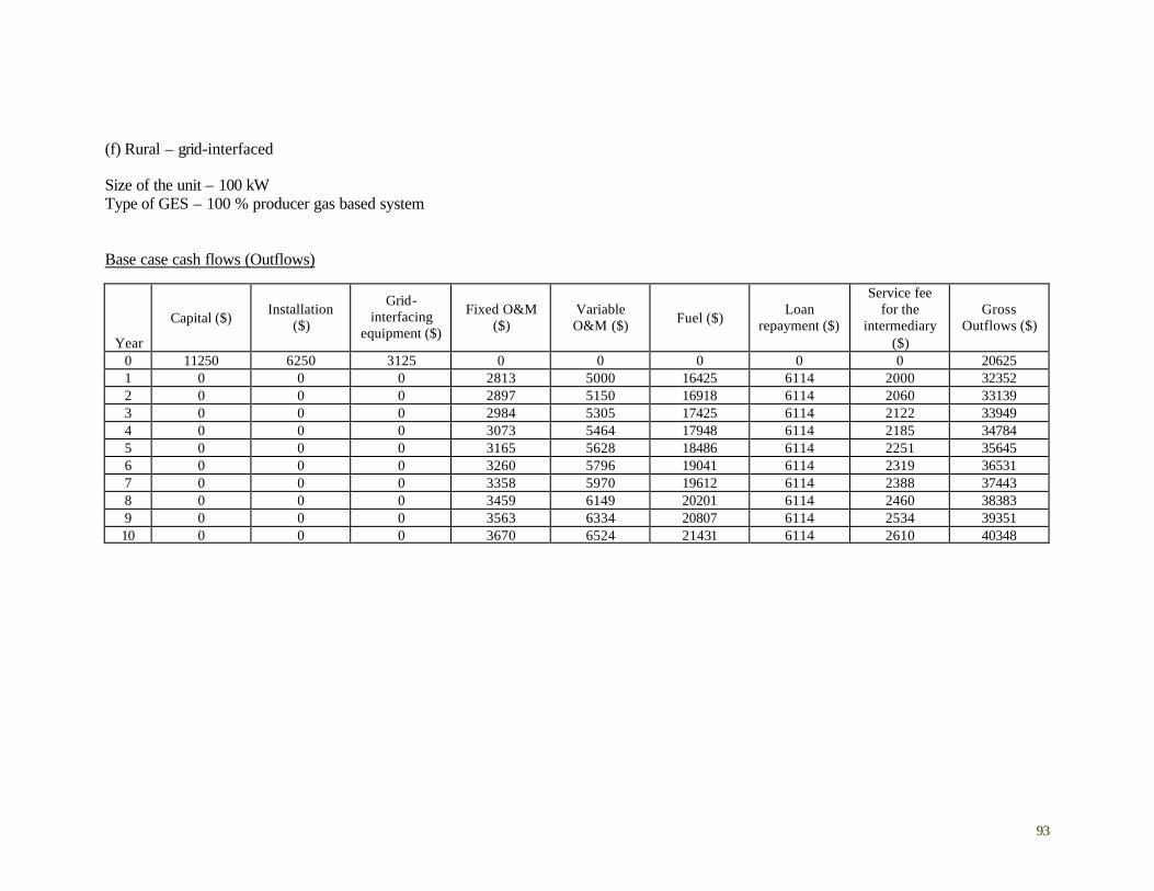
93
(f) Rural – grid-interfaced Size of the unit – 100 kW Type of GES – 100 % producer gas based system Base case cash flows (Outflows)
Year
Capital ($) Installation
($)
Grid-interfacing
equipment ($)
Fixed O&M ($)
Variable O&M ($) Fuel ($)
Loan repayment ($)
Service fee for the
intermediary ($)
Gross Outflows ($)
0 11250 6250 3125 0 0 0 0 0 20625 1 0 0 0 2813 5000 16425 6114 2000 32352 2 0 0 0 2897 5150 16918 6114 2060 33139 3 0 0 0 2984 5305 17425 6114 2122 33949 4 0 0 0 3073 5464 17948 6114 2185 34784 5 0 0 0 3165 5628 18486 6114 2251 35645 6 0 0 0 3260 5796 19041 6114 2319 36531 7 0 0 0 3358 5970 19612 6114 2388 37443 8 0 0 0 3459 6149 20201 6114 2460 38383 9 0 0 0 3563 6334 20807 6114 2534 39351 10 0 0 0 3670 6524 21431 6114 2610 40348

94
(f) Rural – grid-interfaced (continued)
Base case cash flows (Inflows)
Year
Tax saving on depreciation ($)
Revenue from electricity sale to
domestic consumers ($)
Revenue from electricity sale for
productive applications ($)
Revenue from electricity sale to
the grid ($) Gross Inflow ($) Net Inflow ($)
PV of cash flow ($)
0 0 0 0 0 0 -20625 -20625 1 1688 608 3093 30660 36049 3697 3361 2 1688 818 4033 30963 37501 4362 3605 3 1688 1063 5064 31140 38954 5005 3760 4 1688 1349 6186 31174 40397 5612 3833 5 1688 1682 7401 31045 41816 6171 3832 6 1688 2068 8707 30734 43197 6666 3763 7 1688 2515 10104 30218 44524 7081 3634 8 1688 3030 11594 29471 45782 7399 3452 9 1688 3622 13175 28468 46953 7602 3224 10 1688 4303 14847 27179 48017 7669 2957
PV of recurring cash flows/initial capital outlay = 1.72 IRR= 23%

95
A3.2a. Assumptions for levelized cost56 and cash flow calculations: cost parameters57 1. Capital costs Thermal applications’ gasifier capital costs (for all capacity ranges)- 125$/kW Power applications’ gasifier capital costs±
Unit capacity range (kW) Capital cost ($/kW)
Small (10-50) 200
Medium (50-200) 146
Large (500) 106 ±Includes cost of the gasifier along with the gas cleaning/cooling system
Engine type Capital cost ($/kW)
Dual fuel 104
100% PG 417
2. Operation and Maintenance Costs Fixed O&M (annual): 5 % of capital costs (for both power and thermal applications) Variable gasifier O&M costs, thermal applications:§
Application category Gasifier Unit Capacity
Additional manpower requirements
Salary per month ($)
Small (30 kW) No additional requirement
SME Medium (100 kW) 1 unskilled person 42
Small (10 kW) 1 semi-skilled person servicing 20 gasifier units in a cluster
42
Informal sector
Small (30 kW) 1 semi-skilled person servicing 10 gasifier units in a cluster
42
§ This estimates the additional manpower requirements for operating a gasifier-based system over existing liquid -fuel or solid-biomass-burning systems. Note: In addition to the manpower costs, incremental variable O&M costs also include the costs of blower operation @8 ¢/hr for a 100kW system, @4 ¢/hour for a 30kW system, and @2 ¢/hour for a 10kW system
56 All figures are in 2001-02 prices. The exchange rate of Rs.48 to US$1is assumed for cost conversions. 57 Unless otherwise stated, all cost figures are based on manufacturers’ data sheets compiled by TERI, internal documents available from different institutions, and authors’ best estimates based on current prevailing practices and from their own experiences. It should be noted that capital cost assumptions for gasifiers and engines are based on lowest cost quoted by different manufacturers.

96
Variable gasifier O&M costs, power applications:
Application category
Gasifier Unit
Capacity
No of skilled persons
No of unskilled persons
Monthly salary, skilled person ($/8-hr shift)
Monthly salary, unskilled person
($/8-hr shift)
Medium 1 3 167 42 Large captive
Large 2 4 167 42
Small 1 2 167 42 Small and Medium Enterprises (SMEs) Medium 1 3 167 42
Rural/Remote Small 1 2 42 21
Medium 1 3 83 42 Grid-interfaced
Large 1 4 83 42
Note: In addition to the manpower costs, incremental variable O&M costs also include the costs of blower operation @8 ¢/hr for a 100kW system, @4 ¢/hour for a 30kW system, and @2 ¢/hour for a 10kW system Variable O&M costs, diesel engine operation for power applications
Application ($/person/8 hr shift)
Large captive 167
SME 167
Rural/Remote 42
Grid-interfaced 167
3. Fuel Costs Biomass cost
Application category Biomass cost (¢/kg)
Large Captive 1
SME 3
Informal sector 2
Rural/remote 2
Grid-interfaced 3
Diesel cost – 42 ¢/liter

97
4. Installation cost items (includes the cost of construction of civil works, retrofitting and other costs associated with system installation)
Application category Cost (US$)
SME 10 percent of the gasifier capital cost Thermal
Informal sector 10 percent of the gasifier capital cost
Large Captive 6250
SME 6250
Rural/remote 6250 Power
Grid-interfaced 6250 plus an additional cost of 3125 for grid-interfacing
5. Costs for setting up mini-grid in rural/remote area electrification
Gasifier unit size 30 kW
No of households connected 60
Length of the mini-grid 1 km
Investment cost for setting up mini grid $3646
6. Service fee for the entrepreneur/NGO
Application category Unit size Service fee ($/month/per gasifier)
Rural/remote 30 kW 104 (for the NGO)
10 kW 5 (for the entrepreneur) Informal sector†
30 kW 10 (for the entrepreneur)
100kW 167 (for the entrepreneur) Grid-interfaced
500 kW 208 (for the entrepreneur) † The entrepreneur provides energy services to a cluster of firms in the informal sector. The assumption here is that the entrepreneur provides services to ten firms in a cluster with firms with 10kW gasifiers, and to five firms in a cluster with firms with 10kW gasifiers. Thus service fee for the entrepreneur from a single cluster operation is assumed to be approx. $100 per month. 7. Cost of power supply from the grid – 7.3 ¢/kWh58 58 Source: Annual Report on the working of State Electricity Boards and Electricity Departments, May 2002 (http://planningcommission.nic.in)
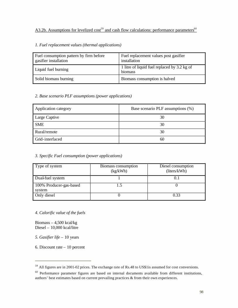
98
A3.2b. Assumptions for levelized cost59 and cash flow calculations: performance parameters60 1. Fuel replacement values (thermal applications) Fuel consumption pattern by firm before gasifier installation
Fuel replacement values post gasifier installation
Liquid fuel burning 1 litre of liquid fuel replaced by 3.2 kg of biomass
Solid biomass burning Biomass consumption is halved
2. Base scenario PLF assumptions (power applications)
Application category Base scenario PLF assumptions (%)
Large Captive 30
SME 30
Rural/remote 30
Grid-interfaced 60
3. Specific Fuel consumption (power applications) Type of system Biomass consumption
(kg/kWh) Diesel consumption
(liters/kWh)
Dual-fuel system 1 0.1
100% Producer-gas-based system
1.5 0
Only diesel 0 0.33
4. Calorific value of the fuels Biomass – 4,500 kcal/kg Diesel – 10,000 kcal/litre 5. Gasifier life – 10 years 6. Discount rate – 10 percent
59 All figures are in 2001-02 prices. The exchange rate of Rs.48 to US$1is assumed for cost conversions. 60 Performance parameter figures are based on internal documents available from different institutions, authors’ best estimates based on current prevailing practices & from their own experiences.
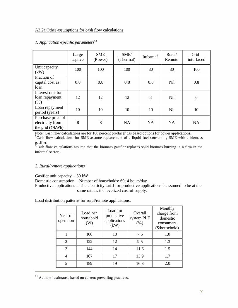
99
A3.2a Other assumptions for cash flow calculations
1. Application-specific parameters61
Large captive
SME (Power)
SME§ (Thermal) Informal† Rural/
Remote Grid-
interfaced
Unit capacity (kW) 100 100 100 30 30 100
Fraction of capital cost as loan
0.8 0.8 0.8 0.8 Nil 0.8
Interest rate for loan repayment (%)
12 12 12 8 Nil 6
Loan repayment period (years) 10 10 10 10 Nil 10
Purchase price of electricity from the grid (¢/kWh)
8 8 NA NA NA NA
Note: Cash flow calculations are for 100 percent producer gas based options for power applications. §Cash flow calculations for SME assume replacement of a liquid fuel consuming SME with a biomass gasifier. †Cash flow calculations assume that the biomass gasifier replaces solid biomass burning in a firm in the informal sector. 2. Rural/remote applications Gasifier unit capacity – 30 kW Domestic consumption – Number of households: 60; 4 hours/day Productive applications – The electricity tariff for productive applications is assumed to be at the same rate as the levelized cost of supply. Load distribution patterns for rural/remote applications:
Year of operation
Load per household
(W)
Load for productive
applications (kW)
Overall system PLF
(%)
Monthly charge from
domestic consumers
($/household) 1 100 10 7.5 1.0
2 122 12 9.5 1.3
3 144 14 11.6 1.5
4 167 17 13.9 1.7
5 189 19 16.3 2.0
61 Authors’ estimates, based on current prevailing practices.
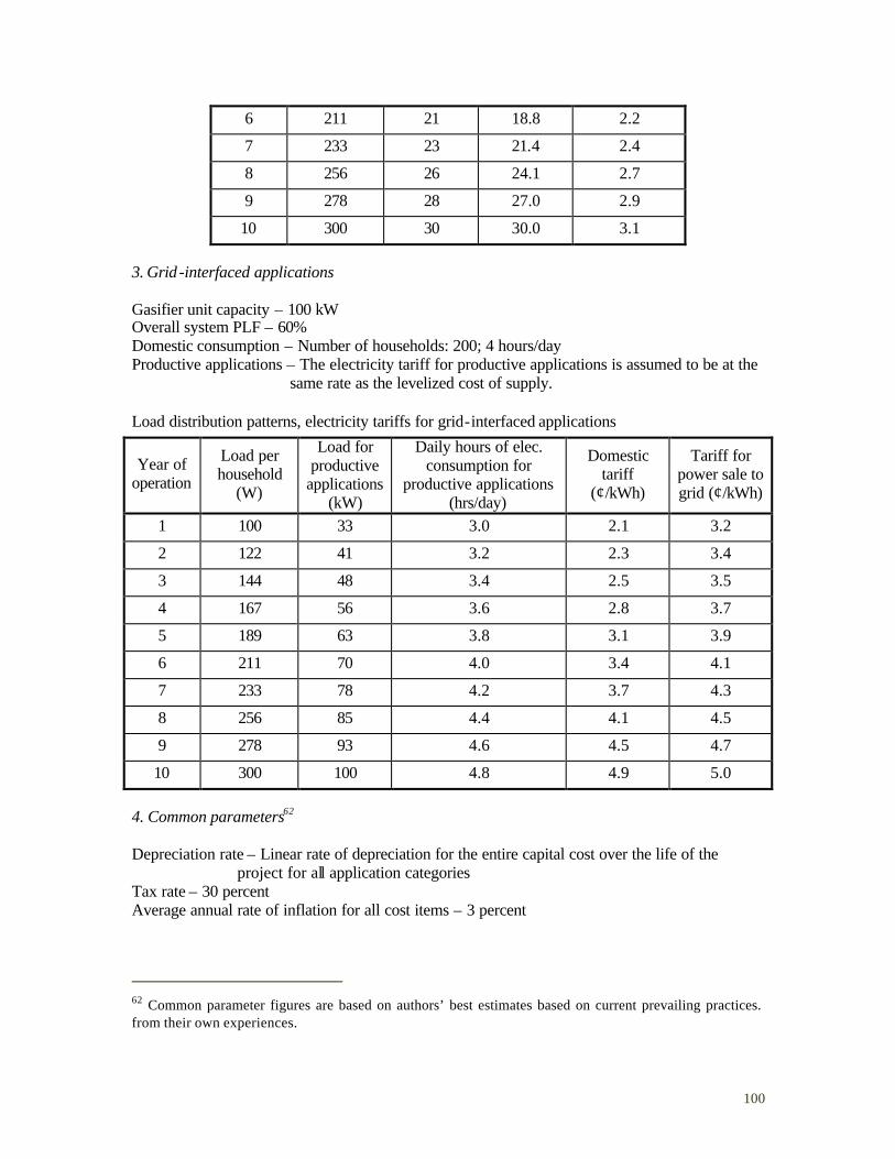
100
6 211 21 18.8 2.2
7 233 23 21.4 2.4
8 256 26 24.1 2.7
9 278 28 27.0 2.9
10 300 30 30.0 3.1
3. Grid -interfaced applications Gasifier unit capacity – 100 kW Overall system PLF – 60% Domestic consumption – Number of households: 200; 4 hours/day Productive applications – The electricity tariff for productive applications is assumed to be at the same rate as the levelized cost of supply. Load distribution patterns, electricity tariffs for grid-interfaced applications
Year of operation
Load per household
(W)
Load for productive
applications (kW)
Daily hours of elec. consumption for
productive applications (hrs/day)
Domestic tariff
(¢/kWh)
Tariff for power sale to grid (¢/kWh)
1 100 33 3.0 2.1 3.2
2 122 41 3.2 2.3 3.4
3 144 48 3.4 2.5 3.5
4 167 56 3.6 2.8 3.7
5 189 63 3.8 3.1 3.9
6 211 70 4.0 3.4 4.1
7 233 78 4.2 3.7 4.3
8 256 85 4.4 4.1 4.5
9 278 93 4.6 4.5 4.7
10 300 100 4.8 4.9 5.0
4. Common parameters62 Depreciation rate – Linear rate of depreciation for the entire capital cost over the life of the project for all application categories Tax rate – 30 percent Average annual rate of inflation for all cost items – 3 percent
62 Common parameter figures are based on authors’ best estimates based on current prevailing practices. from their own experiences.
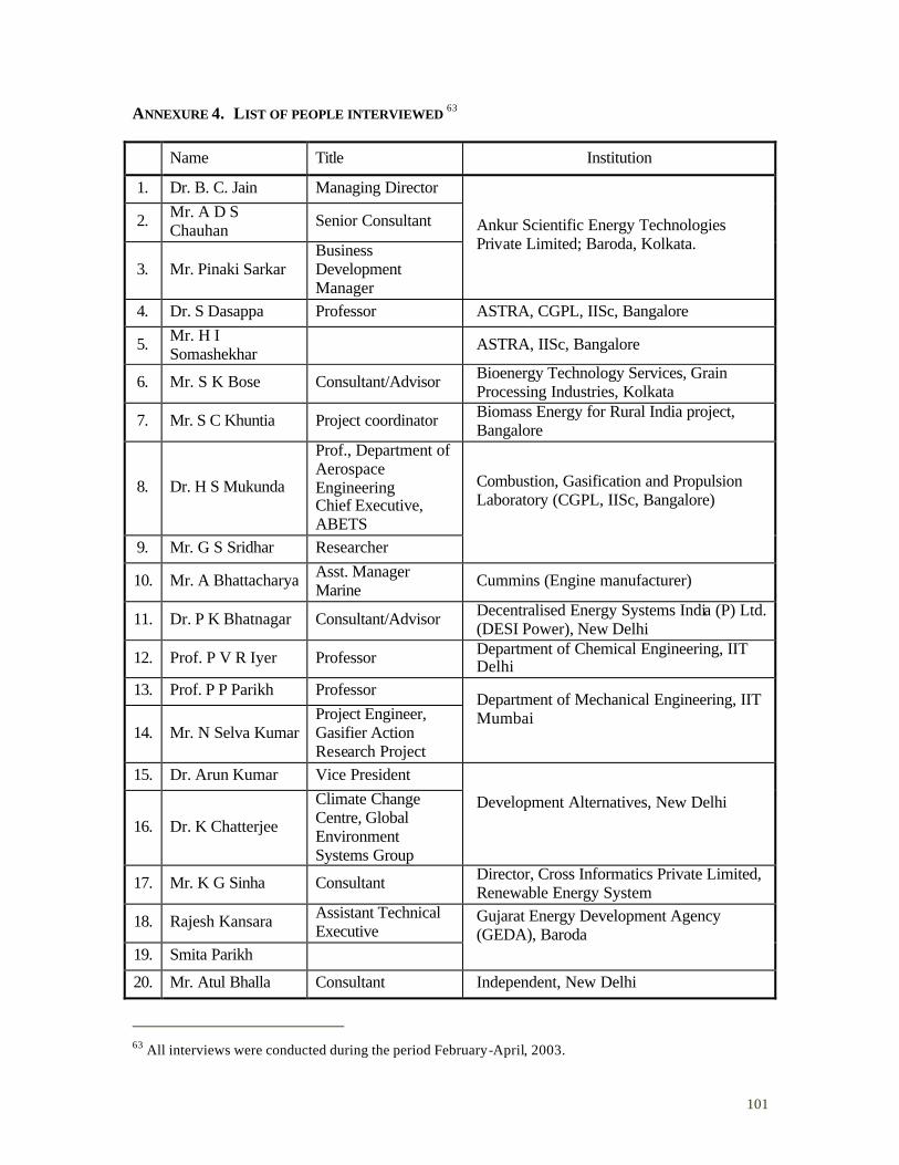
101
ANNEXURE 4. LIST OF PEOPLE INTERVIEWED 63
Name Title Institution
1. Dr. B. C. Jain Managing Director
2. Mr. A D S Chauhan Senior Consultant
3. Mr. Pinaki Sarkar Business Development Manager
Ankur Scientific Energy Technologies Private Limited; Baroda, Kolkata.
4. Dr. S Dasappa Professor ASTRA, CGPL, IISc, Bangalore
5. Mr. H I Somashekhar ASTRA, IISc, Bangalore
6. Mr. S K Bose Consultant/Advisor Bioenergy Technology Services, Grain Processing Industries, Kolkata
7. Mr. S C Khuntia Project coordinator Biomass Energy for Rural India project, Bangalore
8. Dr. H S Mukunda
Prof., Department of Aerospace Engineering Chief Executive, ABETS
9. Mr. G S Sridhar Researcher
Combustion, Gasification and Propulsion Laboratory (CGPL, IISc, Bangalore)
10. Mr. A Bhattacharya Asst. Manager Marine Cummins (Engine manufacturer)
11. Dr. P K Bhatnagar Consultant/Advisor Decentralised Energy Systems India (P) Ltd. (DESI Power), New Delhi
12. Prof. P V R Iyer Professor Department of Chemical Engineering, IIT Delhi
13. Prof. P P Parikh Professor
14. Mr. N Selva Kumar Project Engineer, Gasifier Action Research Project
Department of Mechanical Engineering, IIT Mumbai
15. Dr. Arun Kumar Vice President
16. Dr. K Chatterjee
Climate Change Centre, Global Environment Systems Group
Development Alternatives, New Delhi
17. Mr. K G Sinha Consultant Director, Cross Informatics Private Limited, Renewable Energy System
18. Rajesh Kansara Assistant Technical Executive
19. Smita Parikh
Gujarat Energy Development Agency (GEDA), Baroda
20. Mr. Atul Bhalla Consultant Independent, New Delhi
63 All interviews were conducted during the period February-April, 2003.
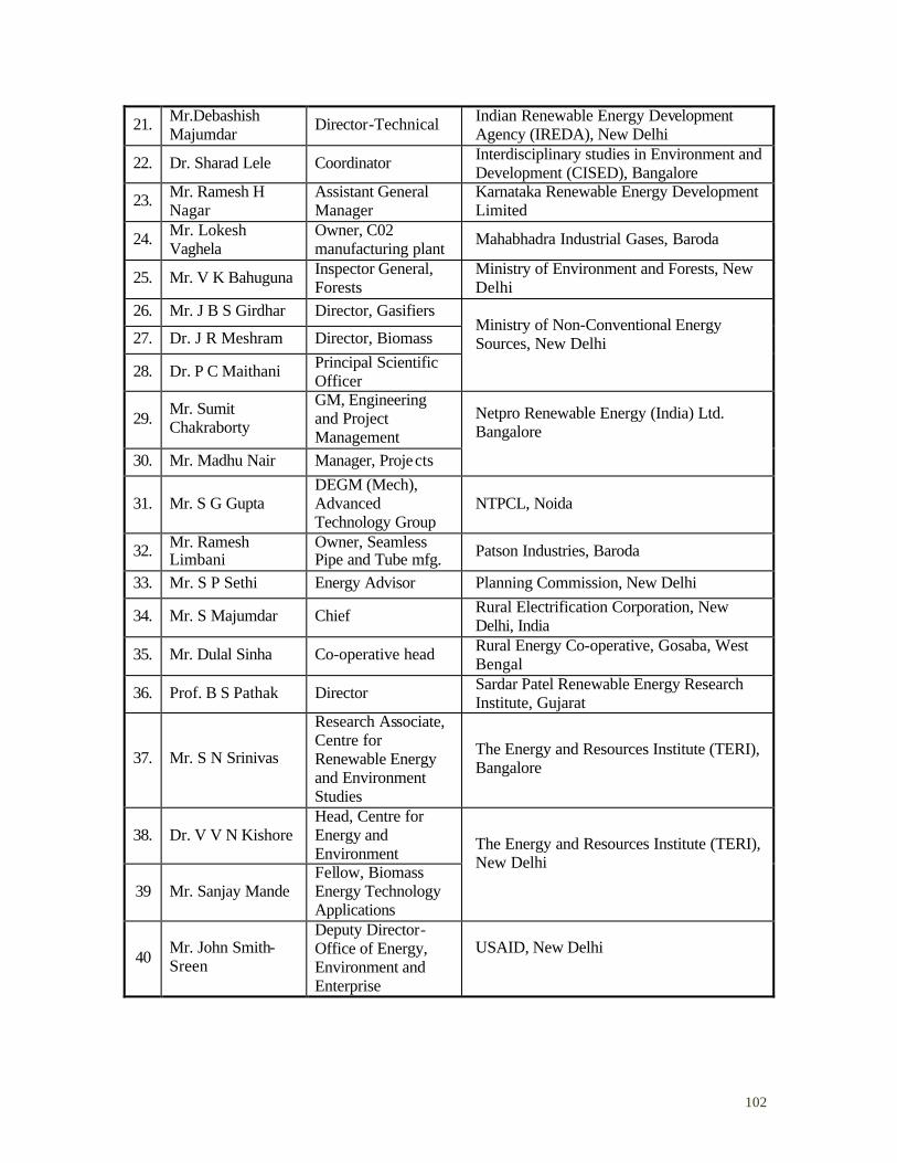
102
21. Mr.Debashish Majumdar Director-Technical Indian Renewable Energy Development
Agency (IREDA), New Delhi
22. Dr. Sharad Lele Coordinator Interdisciplinary studies in Environment and Development (CISED), Bangalore
23. Mr. Ramesh H Nagar
Assistant General Manager
Karnataka Renewable Energy Development Limited
24. Mr. Lokesh Vaghela
Owner, C02 manufacturing plant Mahabhadra Industrial Gases, Baroda
25. Mr. V K Bahuguna Inspector General, Forests
Ministry of Environment and Forests, New Delhi
26. Mr. J B S Girdhar Director, Gasifiers
27. Dr. J R Meshram Director, Biomass
28. Dr. P C Maithani Principal Scientific Officer
Ministry of Non-Conventional Energy Sources, New Delhi
29. Mr. Sumit Chakraborty
GM, Engineering and Project Management
30. Mr. Madhu Nair Manager, Projects
Netpro Renewable Energy (India) Ltd. Bangalore
31. Mr. S G Gupta DEGM (Mech), Advanced Technology Group
NTPCL, Noida
32. Mr. Ramesh Limbani
Owner, Seamless Pipe and Tube mfg. Patson Industries, Baroda
33. Mr. S P Sethi Energy Advisor Planning Commission, New Delhi
34. Mr. S Majumdar Chief Rural Electrification Corporation, New Delhi, India
35. Mr. Dulal Sinha Co-operative head Rural Energy Co-operative, Gosaba, West Bengal
36. Prof. B S Pathak Director Sardar Patel Renewable Energy Research Institute, Gujarat
37. Mr. S N Srinivas
Research Associate, Centre for Renewable Energy and Environment Studies
The Energy and Resources Institute (TERI), Bangalore
38. Dr. V V N Kishore Head, Centre for Energy and Environment
39 Mr. Sanjay Mande Fellow, Biomass Energy Technology Applications
The Energy and Resources Institute (TERI), New Delhi
40 Mr. John Smith-Sreen
Deputy Director- Office of Energy, Environment and Enterprise
USAID, New Delhi
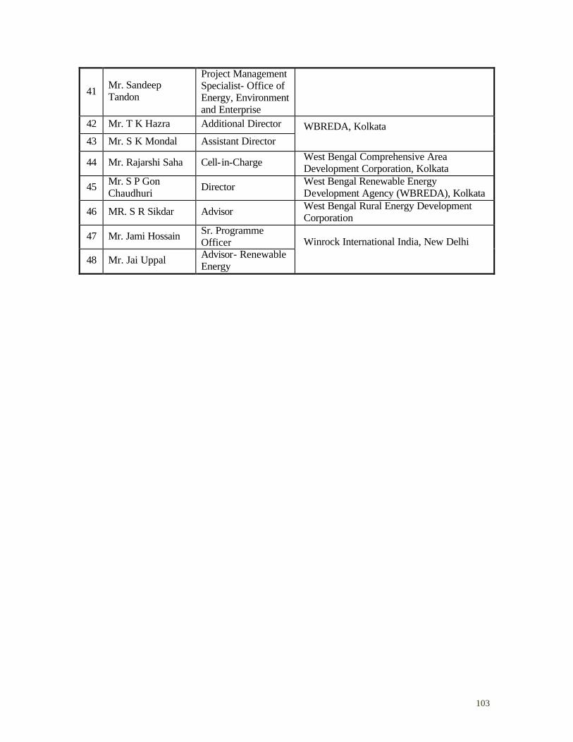
103
41 Mr. Sandeep Tandon
Project Management Specialist- Office of Energy, Environment and Enterprise
42 Mr. T K Hazra Additional Director
43 Mr. S K Mondal Assistant Director WBREDA, Kolkata
44 Mr. Rajarshi Saha Cell-in-Charge West Bengal Comprehensive Area Development Corporation, Kolkata
45 Mr. S P Gon Chaudhuri Director West Bengal Renewable Energy
Development Agency (WBREDA), Kolkata
46 MR. S R Sikdar Advisor West Bengal Rural Energy Development Corporation
47 Mr. Jami Hossain Sr. Programme Officer
48 Mr. Jai Uppal Advisor- Renewable Energy
Winrock International India, New Delhi
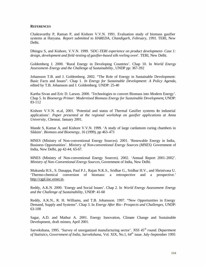
104
REFERENCES
Chakravarthy P, Raman P, and Kishore V.V.N. 1991. Evaluation study of biomass gasifier systems at Haryana. Report submitted to HAREDA, Chandigarh, February, 1991. TERI, New Delhi. Dhingra S, and Kishore, V.V.N. 1999. ‘SDC-TERI experience on product development- Case 1: design, development and field -testing of gasifier-based silk reeling oven’. TERI, New Delhi. Goldemberg J. 2000. ‘Rural Energy in Developing Countries’. Chap 10. In World Energy Assessment- Energy and the Challenge of Sustainability , UNDP pp: 367-392 Johansson T.B. and J. Goldemberg. 2002. “The Role of Energy in Sustainable Development: Basic Facts and Issues”. Chap 1. In Energy for Sustainable Development: A Policy Agenda, edited by T.B. Johansson and J. Goldemberg. UNDP: 25-40 Kartha Sivan and Eric D. Larson. 2000. ‘Technologies to convert Biomass into Modern Energy’. Chap 5. In Bioenergy Primer: Modernised Biomass Energy for Sustainable Development, UNDP: 83-112 Kishore V.V.N. et.al, 2001. ‘Potential and status of Thermal Gasifier systems for industrial applications’. Paper presented at the regional workshop on gasifier applications at Anna University, Chennai. January 2001. Mande S, Kumar A, and Kishore V.V.N. 1999. ‘A study of large cardamom curing chambers in Sikkim’. Biomass and Bioenergy, 16 (1999), pp 463-473 MNES (Ministry of Non-conventional Energy Sources). 2001. ‘Renewable Energy in India, Business Opportunities’. Ministry of Non-conventional Energy Sources (MNES) Government of India, New Delhi, pp 42-44; 65-67. MNES (Ministry of Non-conventional Energy Sources). 2002. ‘Annual Report 2001-2002’. Ministry of Non-Conventional Energy Sources, Government of India, New Delhi. Mukunda H.S., S. Dasappa, Paul P.J., Rajan N.K.S., Sridhar G., Sridhar H.V., and Shrinivasa U. ‘Thermo-chemical conversion of biomass: a retrospective and a prospective.’ http://cgpl.iisc.ernet.in. Reddy, A.K.N. 2000. ‘Energy and Social Issues’. Chap 2. In World Energy Assessment- Energy and the Challenge of Sustainability, UNDP: 41-60 Reddy, A.K.N., R. H. Williams, and T.B. Johansson. 1997. “New Opportunities in Energy Demand, Supply and Systems”. Chap 3. In Energy After Rio - Prospects and Challenges, UNDP: 63-108 Sagar, A.D. and Mathur A. 2001. Energy Innovation, Climate Change and Sustainable Development, draft mimeo, April 2001. Sarvekshana, 1995. ‘Survey of unorganized manufacturing sector’. NSS 45 th round. Department of Statistics, Government of India, Sarvekshana, Vol. XIX, No.1, 64th issue. July-September 1995
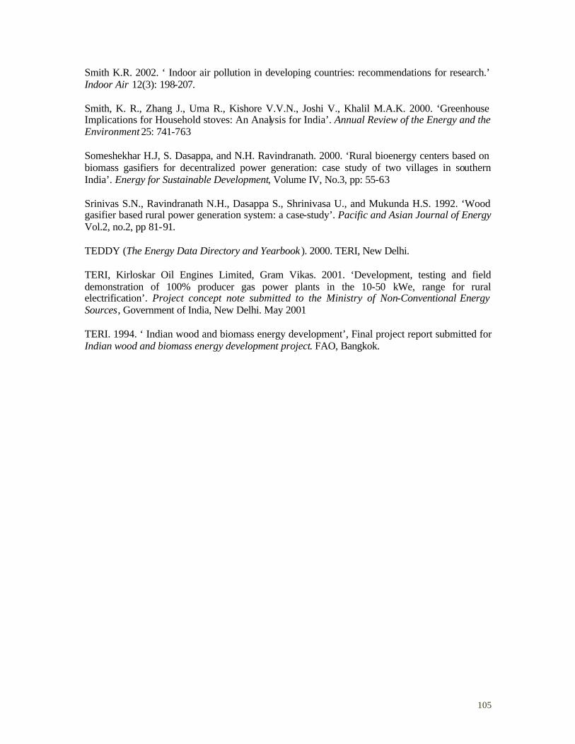
105
Smith K.R. 2002. ‘ Indoor air pollution in developing countries: recommendations for research.’ Indoor Air 12(3): 198-207. Smith, K. R., Zhang J., Uma R., Kishore V.V.N., Joshi V., Khalil M.A.K. 2000. ‘Greenhouse Implications for Household stoves: An Analysis for India’. Annual Review of the Energy and the Environment 25: 741-763 Someshekhar H.J, S. Dasappa, and N.H. Ravindranath. 2000. ‘Rural bioenergy centers based on biomass gasifiers for decentralized power generation: case study of two villages in southern India’. Energy for Sustainable Development, Volume IV, No.3, pp: 55-63 Srinivas S.N., Ravindranath N.H., Dasappa S., Shrinivasa U., and Mukunda H.S. 1992. ‘Wood gasifier based rural power generation system: a case-study’. Pacific and Asian Journal of Energy Vol.2, no.2, pp 81-91. TEDDY (The Energy Data Directory and Yearbook ). 2000. TERI, New Delhi. TERI, Kirloskar Oil Engines Limited, Gram Vikas. 2001. ‘Development, testing and field demonstration of 100% producer gas power plants in the 10-50 kWe, range for rural electrification’. Project concept note submitted to the Ministry of Non-Conventional Energy Sources, Government of India, New Delhi. May 2001 TERI. 1994. ‘ Indian wood and biomass energy development’, Final project report submitted for Indian wood and biomass energy development project. FAO, Bangkok.
106
BIBLIOGRAPHY
Barnett A. 1990. ‘The Diffusion of Energy Technology in the Rural Areas of Developing Countries: A synthesis of Recent Experience’. World Development, Vol.18, No.4, pp.539-553 Carlsson Bo (ed.), 1997. Technological systems and industrial dynamics. Kluwer Academic Publishers CEA (Central Electricity Authority). 2002. ‘Status and progress of rural electrification programme’. Central Electricity Authority (CEA) and Ministry of Power (MoP), Government of India, New Delhi. Dasappa S., Shrinivasa U., Baliga B.N. and Mukunda H.S. 1989. ‘Five-kilowatt wood gasifier technology: Evolution and field experience’. Sadhana, Vol.14, Part 3, pp 187-212 Dhingra S, Mande S, Kishore V.V. N. and Joshi V. 1997. ‘Briquetting of biomass in India: status and potential’. FAO’s RWEDP Report No.23 FAO, Bangkok. Hall,T.B.and Larson,R.1997. ‘A wood-gas stove for developing countries’ in Bridgwater,A.V.and Boocock,D.G.B.(ed.) Developments in Thermochemical Biomass Conversion, Blackie Academic and Professional Press, London. Holdren J.P. and K.R. Smith. 2000. ‘Energy, the Environment and Health’. Chap 3. In World Energy Assessment- Energy and the Challenge of Sustainability, UNDP pp: 61-110 Hosier R. and M. Sharma. 2000. ‘Global Environmental Facility Support for modernized biomass energy: experiences from UNDP and the World Bank’. Energy for Sustainable Development, Volume IV, No.3, pp 83-89 Jain B.C. 2000. ‘Commercializing biomass gasifiers: Indian experience’. Energy for Sustainable Development, Volume IV, No.3, pp: 72-82 Jain B.C. 1995. ‘Facilitating wise bioresource development and use- the role of commercial enterprises’. Energy for Sustainable Development, Volume 1, No.5, pp: 35-44 Kishore V.V.N. 1999. ‘Energy use in traditional industries’. Paper presented at Regional Congress on Traditional Science and Technologies, 24 June 1999, Chirala, AP, India. Kishore V.V.N. 1997. ‘Renewable energy technologies for India: imports vs. indigenous development’ in Venkata Ramana P. (ed.) Rural and renewable energy: perspectives from developing countries. TERI, New Delhi, pp 67-83. Kishore V.V.N and Srinivas S.N. 2001. ‘Biofuels for India’, Journal of Scientific and Industrial Research, CSIR. Larson Eric D., and Kartha S. 2000. ‘Expanding roles for modernized biomass energy’. Energy for Sustainable Development. Volume IV No.3, pp 15-42 Lele Sharadchandra. 1994. ‘Sustainable use of biomass resources: a note on definitions, criteria and practical applications’. Energy for Sustainable Development, Vol. I No.4.

107
Lundvall B.A. (ed.), 1992. National systems of innovation: towards a theory of innovation and interactive learning. Pinter: London Malhotra P., Dutta S., Pal R.C., Sharma S., and Ramana P.V. 2000. Rural energy matters- the Dhanwas experience. TERI, New Delhi, pp 81-87. Mande S, Pai B.R. and Kishore V.V.N. 2000. ‘Study of stoves used in silk reeling industry’. Biomass and Bioenergy, 19 (2000), pp 51-61. Mathur Ajay. 1997. ‘Development and deployment of renewable energy technologies in India: a technology perspective’ in Venkata Ramana P. (ed.) Rural and renewable energy: perspectives from developing countries. TERI, New Delhi, pp 251-269 Metz Bert, Ogunlade Davidson, Jan-Willem Martens, Sascha Van Rooijen and Laura Van Wie Mcgrory (Eds.). 2000. Methodological and Technological Issues in Technology Transfer. Special Report of the Intergovernmental Panel on Climate Change. Cambridge University Press, UK Mukunda H.S., S. Dasappa, and Shrinivasa U. 1993. ‘Open-top Wood Gasifiers’. In Renewable Energy: Sources for Fuels and Electricity , edited by T.B. Johansson, H. Kelly, A.K.N. Reddy and R.H. Williams. Washington, DC: Island Press, pp 699-728 Mukunda H.S., Dasappa S., Paul P.J., Rajan N.K.S., Shrinivasa U. 1994. ‘Gasifiers and combustors for biomass- technology and field studies’. Energy for Sustainable Development. Volume I, No.3, pp 27-38 Mukunda H.S., Paul P.J. 1994. ‘Results of an Indo-Swiss programme for qualification and testing of a 300-kW IISc-Dasag gasifier’. Energy for Sustainable Development. Volume 1, No.4, pp 46-49 PCAST Energy R&D Panel. 1999. Powerful Partnerships: The Federal Role in International Cooperation on Energy Innovation. Report from the Panel on International Cooperation in Energy Research, Development, Demonstration and Deployment of the President’s Committee of Advisors on Science and Technology, Executive Office of the President of the United States. Quaak P, H. Knoef, and H.E. Stassen. 1999. Energy from Biomass: A Review of Gasification and Combustion Technologies. Energy Series, World Bank Technical Paper No. 422. Washington DC, World Bank. Ramana P.V., and Joshi V. 1997. ‘Use of biomass fuels in India - trends and issues’, in Venkata Ramana P. (ed.) Rural and renewable energy: perspectives from developing countries. TERI, New Delhi, pp 155-167. Ravindranath N.H., Mukunda H.S. and Srinivas S.N. 1992. ‘Rural Energy Centre based on Energy Forest-Wood Gasifier System’ in Singh K.K., Mathur A.N., Patil S.B., Srivastava P.R. (ed.), Action Research & Development in Biomass Gasification. Proceeding of III National Meet/PICCOP New Delhi, pp 351-355. REC (Rural Electrification Corporation), 1999. Annual report, Rural electrification corporation (REC), New Delhi.
108
Reed T.B. (ed.). 1981. Biomass Gasification- Principles and Technology. Solar Energy Research Institute, Golden CO. Reed, T. B, and Gaur S. 2001. ‘A survey of biomass gasification 2000: gasifier projects and manufacturers around the world’. 2nd edition. The National Renewable Energy Laboratory and the Biomass Energy Foundation, Golden. CO. Senelwa K. and R.E.H. Sims. 1999. ‘Opportunities for small-scale biomass-electricity systems in Kenya’. Biomass and Bioenergy 17: 239-255 Sharan H.N., Mukunda H.S., Shrinivasa U., Dasappa S., Paul P.J. and Rajan N.K.S. 1997. ‘IISc-DASAG biomass gasifiers: Development, technology, experience and economics’ in Bridgewater A.V. and Boocock D.G.B (ed.) Developments in Thermocehmical biomass conversion. Volume 2. Blackie Academic and Professional, pp 1058-1072. Siemons R.V. 2001. ‘Identifying a role for biomass gasification in rural electrification in developing countries: the economic perspective’. Biomass and Bioenergy 20: 271 –285 Srinivas S.N. 2000. ‘Biomass consumption in unorganized enterprises in India’. Biomass Users’ Network Newsletter, Vol. 3.3, pp 2-4, July 2000. Srinivas S.N. 1993. ‘Techno-economic Improvements to Rural Service System- Case Study of Hosahalli’, in Paul P.J. and Mukunda H.S. (ed.) Proceedings of the Fourth National Meet on Biomass Gasification and Combustion, Interline Publishing. Stassen H.E.M. 1995. Small-Scale Biomass Gasifiers for Heat and Power: A Global Review. Energy Series, World Bank Technical Paper No. 296. Washington DC, World Bank Vipradas M. (ed.). 2001. Renewables: Products and Markets, TERI, New Delhi, pp 33-46 World Bank. 2000. Energy Services for the World’s Poor. Energy Sector Management Assistance Programme. World Bank: Washington, D.C World Bank. 1996. Rural energy and development: improving energy supplies for two billion people . World Bank: Washington, D.C