Embed Size (px)
Citation preview

Scanning delay line with a rotating-parallelogramprism for low-coherence interferometry
Linas Giniu#nas, Romualdas Danielius, and Remigijus Karkockas
We describe a fast scanning optical delay line for low-coherence interferometry that has good linearity,a high duty cycle, and a continuously adjustable scan range. The delay line consists of a rotating-parallelogram prism with the rotation axis tilted with respect to the incident beam and two motionlessmirrors. The delay line is well suited for nearly simultaneous distance measurements at two differentdepths, which is useful for making absolute and differential distance measurements. © 1999 OpticalSociety of America
OCIS codes: 060.2370, 110.4500, 120.3180, 120.5800, 150.6910, 170.4500.
6,7
aqlmppt
tf
1. Introduction
Optical coherence domain reflectometry is a power-ful technique with a variety of applications rangingfrom fault location in optical waveguide devices1 tobiomedical imaging.2,3 This technique has alsobeen demonstrated to be useful for absolute dis-tance measurements in human eye4 and moltenglass level measurement.5 The principle of opera-tion of the coherence domain reflectometry relies onthe interference of low-coherence light in aMichelson-type interferometer. The interferencesignal occurs when the optical path length in thesample arm of the interferometer coincides withthat in the reference arm. The length of the ref-erence arm is scanned periodically. The sensitiv-ity, accuracy, and data-acquisition rate of themethod depend very much on the optical delay lineused in the reference arm of the interferometer. Amechanically translated mirror is the most obviousexample of a delay line. However, the mechanicaltranslation of the mirror is too slow for many ap-plications. Much faster periodically scanning de-lay lines in which a rotating glass cube is used havebeen able to achieve a scan velocity up to 95 mysover a range of 120 mm and a repetition rate of up
L. Giniu#nas [email protected]! and R. Danielius are withthe Laser Research Center, Vilnius University, Sauletekio al. 10,Vilnius LT-2040, Lithuania. R. Karkockas is with the Depart-ment of Computer Engineering, Kaunas University of Technology,Studentu 50, Kaunas LT-3031, Lithuania.
Received 27 May 1999.0003-6935y99y347076-04$15.00y0© 1999 Optical Society of America
7076 APPLIED OPTICS y Vol. 38, No. 34 y 1 December 1999
to 28 kHz. However, these delay lines sufferfrom a rather low duty cycle if the near-linear partof the scan is considered. A delay line based onstretching the fiber coiled around a cylindricalpiezoelectric transducer has been reported.8,9
Although this approach fits very well into the fiber-optic technology, the drawbacks of this techniqueare drifts resulting from temperature changes, dy-namic birefringence effects, and the necessity of ahigh-voltage source for piezoelectric transducerdriving. The high-speed phase and group delayline with grating-based phase control has also beenreported.9,10 It performed the optical scanningover a range of 3 mm with a scanning rate of 6 mys
nd a repetition rate of 2 kHz. This delay line isuite flexible in changing the scan depth or rate asong as the scanning frequencies are far from the
echanical resonances of the mirror–galvanometerair. The problem is that the device requires ex-ensive and sensitive components such as a diffrac-ion grating and a galvanometer.
Another class of the scanning delay lines based onhe two parallel mirrors mounted on a rotating plat-orm is well known from the early 1980’s.11,12 Al-
though easily implementable, these delay lines havea poor duty cycle that complicates application of themin low-coherence reflectometry.
In this paper we describe a new optical delay line inwhich two parallel mirrors mounted on a rotatingplatform are used. This delay line permits high-speed near-linear scanning with a high duty cycle.Additional advantages also are the possibilities ofcontinuous adjustment of the scanning range fromzero and simultaneous scanning at two depths.
ptrtpapadroo
pasgtdtpe
an
rrt
fitatfsDt
m~pipa
r
2. Theoretical Considerations
Let us first consider a simplified case of the variabledelay line @Fig. 1~a!#. The delay line consists of a
rism that is similar to the Fresnel prism but withhe apex angle of 45°. A collimated light beam iseflected twice inside the prism. The beam behindhe prism remains parallel to the incident one at anyosition of the prism. The mirror reflects the beamnd returns it back in the same way. The opticalath in the delay line varies if we rotate the prismround an axis perpendicular to the plane of therawing. The optical path length decreases if weotate the prism in a clockwise direction. This typef a delay line with two mirrors instead of a parallel-gram prism was considered by Riffe and Sabbah.12
However, such a delay line has a limited duty cyclesince the light beam passes through the aperture onlywithin a small range of angles. The scan range isdefined by the dimensions of the prism, and this cre-ates problems when the needed range is small andthe repetition rate is high. The duty cycle can beincreased by periodical scanning of the prism withsmall angles instead of rotation. Such a delay linewould have a high duty cycle with good linearity,however, the scanning is less convenient than rota-tion in practical terms.
If the prism is rotated around the axis OO) in thelane of the drawing, one can achieve similar resultss in the case of a scanning prism. Figure 1~a!hows the position of the prism when the delay is thereatest, and Fig. 1~b! shows the prism position whenhe delay is the smallest. At other positions, theelay has intermediate values. Variations of the op-ical path length in the delay line ~DL! can be com-letely calculated with the following exactxpression:
DL~Q! 5 H sin~a!1 1 tan~a!cos~Q!
1 2 tan~a!cos~Q!@tan~a! 2 cos~Q!#,
(1)
Here a is the tilt angle, H is the length of the prism,nd Q is rotation angle. The delay variation doesot depend on the thickness of the prism and the
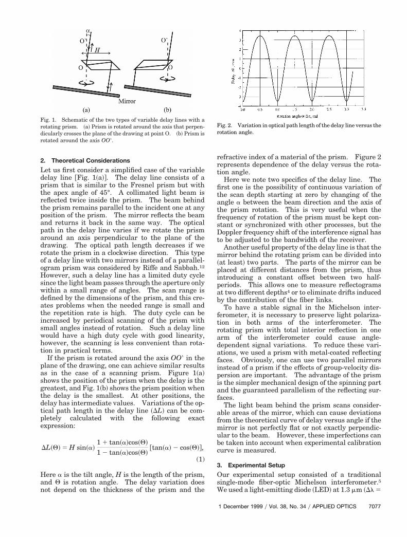
Fig. 1. Schematic of the two types of variable delay lines with arotating prism. ~a! Prism is rotated around the axis that perpen-dicularly crosses the plane of the drawing at point O. ~b! Prism isotated around the axis OO).
efractive index of a material of the prism. Figure 2epresents dependence of the delay versus the rota-ion angle.
Here we note two specifics of the delay line. Therst one is the possibility of continuous variation ofhe scan depth starting at zero by changing of thengle a between the beam direction and the axis ofhe prism rotation. This is very useful when therequency of rotation of the prism must be kept con-tant or synchronized with other processes, but theoppler frequency shift of the interference signal has
o be adjusted to the bandwidth of the receiver.Another useful property of the delay line is that theirror behind the rotating prism can be divided into
at least! two parts. The parts of the mirror can belaced at different distances from the prism, thusntroducing a constant offset between two half-eriods. This allows one to measure reflectogramst two different depths4 or to eliminate drifts induced
by the contribution of the fiber links.To have a stable signal in the Michelson inter-
ferometer, it is necessary to preserve light polariza-tion in both arms of the interferometer. Therotating prism with total interior reflection in onearm of the interferometer could cause angle-dependent signal variations. To reduce these vari-ations, we used a prism with metal-coated reflectingfaces. Obviously, one can use two parallel mirrorsinstead of a prism if the effects of group-velocity dis-persion are important. The advantage of the prismis the simpler mechanical design of the spinning partand the guaranteed parallelism of the reflecting sur-faces.
The light beam behind the prism scans consider-able areas of the mirror, which can cause deviationsfrom the theoretical curve of delay versus angle if themirror is not perfectly flat or not exactly perpendic-ular to the beam. However, these imperfections canbe taken into account when experimental calibrationcurve is measured.
3. Experimental Setup
Our experimental setup consisted of a traditionalsingle-mode fiber-optic Michelson interferometer.5We used a light-emitting diode ~LED! at 1.3 mm ~Dl 5
Fig. 2. Variation in optical path length of the delay line versus therotation angle.
1 December 1999 y Vol. 38, No. 34 y APPLIED OPTICS 7077

7
50 nm! with 150 mW optical power in the fiber and thedescribed delay line with two mirrors in the referencearm of the interferometer. The scan depth of DL 56.9 mm was obtained by means of the tilt angle of the20-mm-long rotating prism, approximately a 5 10°,with the scan nonlinearity being below 10%. Figure3 shows the nonlinear error of the scanning delayline. We measured it by the calibrated displacementof the mirror in the focal plane of the objective arm.The linear part of the curve ~nonlinearity ,1%! is 3mm and corresponds to an angle of rotation of 60° ora duty cycle of 30%. One could increase the dutycycle up to approximately 80% by broadening thebandwidth of the receiver and by further digital pro-cessing. However, this would reduce the signal-to-noise ratio of the system. We rotated the prism at a50-Hz repetition rate, choosing the optimal ratio forthe scan depth, the repetition rate, and the signal-to-noise ratio of the system. In principle, the repetitionrate is limited by the mechanical strength of theprism and driver.
Using the interferometer with a variable delay lineas described above, we built an apparatus for thethree-dimensional mapping of the interior surfaceand the glass thickness distribution of the panel partof cathode ray tubes ~CRT’s! before assembling them.Because the device was used in the manufacturing
Fig. 4. Difference of the profile of interior surface of a CRT panelfrom the ideal sphere ~r 5 840 mm!. The profile was measuredfrom the concave side before the CRT was assembled. Transversedimensions are 33 cm 3 28 cm.
Fig. 3. Nonlinear error of the variable delay line. Linear part is3 mm ~nonlinearity ,1%!.
078 APPLIED OPTICS y Vol. 38, No. 34 y 1 December 1999
line, the time interval for performing the mappingwas limited to a few seconds. Therefore, we applieda single scanning mirror mounted onto a stepper-motor-driven Gimbal-type mount for a probe-beamscanning. This scanning technique is convenient formeasuring concave near-spherical surfaces if thescanning mirror is placed in the center of curvature ofa spherical surface. The variable optical pathlength in the reference arm of the interferometermatched the optical path in the objective arm twotimes during a period of the prism rotation. One ofthe mirrors of the delay line was adjusted to theinterior surface of the screen while the second mirrorwas displaced by 18 mm and adjusted to the exteriorsurface. The signal from the first mirror providedinformation on the profile of the interior surface ~Fig.4!, and the differential signal from the two mirrorsgave us the glass thickness ~Fig. 5!. The images onFigs. 4 and 5 show 300 smoothed measurements ac-quired within 6 s over an area of 33 cm 3 28 cm.
4. Conclusions
We have developed a high duty cycle variable delayline by use of a rotating-parallelogram prism with anaxis of rotation tilted in respect to the light beam.The delay line allows the continuous adjustment ofthe scan depth by changing of the tilt angle. To ourknowledge, this is the first time that such a feature ina delay line that includes an optic rotating at con-stant speed has been constructed. The delay linealso includes two fixed mirrors that can be placed atdifferent distances for nearly simultaneous distancemeasurement at two different depths. We demon-strated the operation of the delay line by installing itin a fiber-optic Michelson interferometer with a scan-ning beam in the objective arm. This was used forthree-dimensional profiling and for measuring theglass thickness distribution in the concave near-spherical glass panel of a CRT. The delay line wasoptimized for this particular application and allowedus to scan linearly at 2- to ;3-mm intervals displacedby 18 mm with a 50-Hz repetition rate and a 30%duty cycle.
Fig. 5. Glass thickness distribution of the same CRT panel asshown at Fig. 4.

7. J. Szydlo, N. Delachenal, R. Giannoti, R. Walti, H. Bleuler, and
References1. K. Takada, I. Yokohama, K. Childa, and J. Noda, “New measure-ment system for fault location in optical waveguide devices basedon interferometric technique,” Appl. Opt. 26, 1603–1606 ~1987!.
2. G. J. Tearney, S. A. Boppart, B. E. Bouma, M. E. Brezinski,N. J. Weissman, J. F. Southern, and J. G. Fujimoto, “Scanningsingle-mode fiber optic catheter–endoscope for optical coher-ence tomography,” Opt. Lett. 21, 543–545 ~1996!.
3. A. F. Fercher, C. Hitzenberger, and M. J. Juchem, “Measure-ment of intraocular optical distances using partially coherentlaser light,” J. Mod. Opt. 38, 1327–1333 ~1991!.
4. A. Gh. Podoleanu, G. M. Dobre, D. J. Webb, D. A. Jackson,“Fiberised set-up for eye length measurement,” Opt. Commun.137, 397–405 ~1997!.
5. L. Giniunas, R. Karkockas, and R. Danielius, “Accurate remotedistance sensing by use of low-coherence interferometry: anindustrial application,” Appl. Opt. 37, 6729–6733 ~1998!.
6. N. Delachenal, R. Gianotti, R. Walti, H. Limberger, and R. P. Sal-athe, “Constant high-speed optical low-coherence reflectometryover 0.12m scan range,” Electron. Lett. 33, 2059–2061 ~1997!.
R. P. Salathe, “Air-turbin driven optical low-coherence reflec-tometry at 28.6 kHz scan repetition rate,” Opt. Commun. 154,1–4 ~1998!.
8. L. M. Simohamed, L. Delage, and F. Reynaud, “Polarizationcontrol in a large stroke optical fiber delay line,” Opt. Lett. 24,95–97 ~1999!.
9. G. J. Tearney, B. E. Bouma, and J. G. Fujimoto, “High-speedphase- and group-delay scanning with a grating-based phase-control delay line,” Opt. Lett. 23, 1811–1813 ~1997!.
10. A. M. Rollins, M. D. Kulkarni, S. Yazdanfar, R. Ung-arunyawee, and J. A. Izatt, “In vivo video rate optical coher-ence tomography,” Opt. Express 3, 219–229 ~1998!. http:yyepubs.osa.orgyoearchive.
11. D. J. Campbell, P. A. Krug, I. S. Falconer, L. C. Robinson, andG. D. Tait, “Rapid scan phase modulator for interferometricapplications,” Appl. Opt. 20, 335–342 ~1981!.
12. D. M. Riffe and A. J. Sabbah, “A compact rotating-mirror au-tocorrelator design for femtosecond and picosecond laser puls-es,” Rev. Sci. Instrum. 69, 3099–3102 ~1998!.
1 December 1999 y Vol. 38, No. 34 y APPLIED OPTICS 7079


![Diffraction grating-based sensing optofluidic device for ... · Wollaston cube prism and Geake circular prism [1, 2]. Refractometers based on interferometry are the Jamin, Mach Zehnder](https://img.pdfslide.net/doc/110x75/5e25ec9f97c6f03b943563a1/diffraction-grating-based-sensing-optofluidic-device-for-wollaston-cube-prism.jpg)