Embed Size (px)
Citation preview
Scanning lidar with a coupled radar safety system
Geoffrey S. Kent and Gary M. Hansen
A small scanning three-wavelength lidar system at NASA Langley Research Center in Hampton, Vir-ginia, has been used since 1992 to make atmospheric measurements on stratospheric and upper tropo-spheric aerosols and on the evolution of aircraft exhaust plumes. Many of these measurements havebeen made away from the zenith, and, to reduce the hazard to air traffic produced by the laser beam, aradar safety device has been installed. The radar application is original in that the radar beam is madecollinear with the laser beam by use of a dichroic mirror that transmits the laser radiation and reflectsthe microwaves. This mirror is inserted into the outgoing optical path prior to the radiation from boththe radar and the laser passing through the independent scanning unit. Tests of the complete systemshow that the lidar and radar beams remain collocated as they are scanned and that the radar can be usedto inhibit the laser prior to an aircraft passing through the beam. © 1999 Optical Society of America
OCIS codes: 010.3640, 120.0280, 140.3360, 280.3640.
h
1. Introduction
Lidar systems making observations of the atmo-sphere employ lasers that often have the potential tocause visual hazards and even eye damage to pilotsand passengers on aircraft.1,2 This is particularly sowhen the laser beams are directed away from thevertical. One solution to this problem has been toemploy a radar system that looks in the same direc-tion as the lidar.3 If an aircraft is detected ap-proaching the laser beam, the system may be shutdown until after the aircraft has passed. Anothersolution has been to employ low-pulse energy, high-pulse repetition rate lasers whose output is withineye-safe limits.4 When radar is used, it must illu-minate a region of the sky surrounding the laserbeam in such a way as to allow sufficient time fordetection and deactivation of the lidar. This may bedifficult when the lidar is used to scan rapidly acrossa range of angles in the sky and the radar is thenrequired to follow the lidar scan pattern.
Such a scanning lidar system is currently in use atNASA Langley Research Center where it has mademeasurements on the three-dimensional structureand evolution of the exhaust plume from jet aircraft.5
The authors are with the Science and Technology Corporation,101 Research Drive, Hampton, Virginia 23666-1340. The e-mailaddress for G. S. Kent is [email protected].
Received 7 December 1998; revised manuscript received 6 July1999.
0003-6935y99y306383-05$15.00y0© 1999 Optical Society of America
Currently, this lidar system is being used to study thestructure of, and signal attenuation in, the uppertroposphere at angles of up to 35° from the vertical.The system has a fixed laser and receiver and thelaser beam is sent through a programmable scanningunit that directs the beam to a particular location inthe sky and receives the scattered radiation from thesame direction. The solution to the problem of eyesafety that has been adopted is to collocate the laserand radar beams before passage through the scan-ning unit in such a way that the exiting laser beam isalways within the radar beam. The collocation ofthe laser and radar beams is achieved through use ofa dichroic mirror that transmits the laser radiationwhile reflecting that from the radar.
2. System Construction
A. Scanning Unit
The lidar system ~independent of the beam scanner!as been described previously.6 The system uses a
30-Hz Nd:YAG laser with a total pulse energy at1064, 532, and 355 nm of approximately 500 mJ.The expanded laser beam, which is concentric withthe received beam, has a diameter of approximately10 cm and exits vertically. The receiving telescopeis Cassegrain and has an aperture of 37 cm. Thescanning subsystem is mounted above the main lidar.This subsystem has not been described and a briefaccount of its construction is given here. The unit isof an altitude–azimuth type and consists of four in-tegrated pieces: the two mirrors, the two motorsand their controller, the mirror housing, and the sup-
20 October 1999 y Vol. 38, No. 30 y APPLIED OPTICS 6383
mtcal1rrmm
amTtrataswapsdoNtovprswctelcTtttFhtfmwSs
ons fo
6
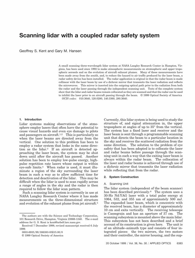
port structure. A schematic of the scan mirrors, themotors, and their housing is shown in Fig. 1~a! ~di-
ensions are given in U.S. Customary Units ratherhan metric units to conform with the design specifi-ations!. The system is designed for full sky cover-ge although this is not possible in its presentocation. The complete housing as shown in Fig.~a! rotates about a vertical axis concentric with theeceiving telescope and laser beam. The second mir-or rotates about a horizontal axis. This arrange-ent maintains the angles of incidence on theirrors at 45° regardless of final beam direction.The scanning mirrors were constructed by bonding
Fig. 1. Scanning subsystem: ~a! side view of the scan mirrorhousing showing the position of both mirrors and the motors and~b! schematic showing the locations of the radar and the dichroicmirror and the positions of the laser and radar beams. All dimen-sions are in inches.
Table 1. Specificati
Item
Glass mirrors Front surfanm, 3-mm90% infr
Honeycomb mirror backing Blue seal tCompleted mirror ~glass and backing! Bonded wit
;0.3 mraElevation motor Klinger Sci
capacityAzimuthal motor Klinger Sci
capacityMovable carriage ~two mirrors, eleva-
tion motor, support frame!Mass ;18
Overall performance Two-axis bbetter.
384 APPLIED OPTICS y Vol. 38, No. 30 y 20 October 1999
thin ~3-mm thickness! first surface mirror to a 25-m-thick piece of honeycombed aluminum ~Hexcel!.his design was driven by the desire to have mirrorshat were light enough to be driven at high scanates, but still low in cost. Two further consider-tions were taken into account in the mirror design:he surface flatness was to be consistent with toler-nces in the rest of the optical system and therehould be no major thermal distortions. The latterere reduced by bonding the glass mirrors to theluminum backing with a flexible RTV ~room tem-erature vulcanizing! adhesive. Measurements ofurface flatness were made by projecting a two-imensional laser spot pattern onto the mirrors andbserving any deviations in the reflected pattern.o appreciable thermal distortion was observed over
he temperature range 10 °C–30 °C. Measurementsf total surface flatness showed the rms angular de-iation of light reflected from either mirror to be ap-roximately 0.3 mrad ~deviations in the centralegion used for the transmitted laser beam werelightly smaller!. The total mass for each mirroras approximately 3.6 kg. The motors and motor
ontroller were made by Klinger Scientific Corpora-ion and were capable of rotating the system aboutither axis at rates greater than 10°ys. The control-er has an RS232C computer interface for computerontrol and programming of specific scan sequences.he system has both software and hardware limitshat can be set to prevent overrotation and damage tohe structure. The two mirrors and the smaller mo-or are mounted within a single frame @as shown inig. 1~a!#. This frame, also constructed from Hexcel,as a total weight ~including the mirrors and eleva-ion motor! of approximately 18 kg and is suspendedrom the larger azimuth motor. The latter isounted on an outer support structure and housedithin a roof aperture in the operating laboratory.pecifications and additional information on thecanning unit are listed in Table 1.
B. Radar System
NASA Langley Research Center has been using acoupled radar system with its vertically pointing li-
r the Scanning Unit
Particulars
luminized, AlSiO overcoated, 0.8-wavesycm flatness at 546ckness, 38 3 53 cm rectangular. Reflectivity 88% visible,
Manufactured by Rolyn Optics.g board from Hexcel. Weight ;5 kgym2.V adhesive, mass 3.6 kg, rms deviation in reflected beam
Negligible thermal distortion 10 °C–30 °C.c Corporation RTN 120CC, top speed .10°ys. Normal loadg, resolution 0.001°, mass 4.2 kg.c Corporation RTN 160CC, top speed .10°ys. Normal loadg, resolution 0.001°, mass 7.0 kg.
Outside dimensions 107 cm 3 61 cm 3 51 cm.
scan rates of up to 10°ys, positioning accuracy of 0.1° orprogrammable. Capable of continuous cyclic operation.
ce, athi
ared.oolinh RTd.entifi120 kentifi180 kkg.
eamFully
ctsiatminsottctTatrtawmcbj
RpfHflot
lww
Table 2. Specifications for the Radar Unit
dar systems for some time, and a description of theradar and its performance has been given.7 The ra-dar, whose characteristics are listed in Table 2, is aFurano marine, X-band radar with a modified an-tenna. The new horn antenna produces a fixed ra-dar beam with a 14° width ~full angle, 3 dB!. Thesystem is electronically interfaced to the lidar sys-tems, inhibiting lasing whenever a reflecting target isdetected by the radar. Tests have been carried outwith aircraft carrying Global Positioning System~GPS! instrumentation to determine the aircraft po-sition relative to the laser beam. In all cases, therewas adequate warning time ~1–8 s! to automaticallyclose down the laser before the aircraft reached thebeam. Detection of several different types of aircraftat altitudes up to over 11 km has also been demon-strated.
C. Design of the Dichroic Mirror
Integration of the radar and the lidar requires thefollowing: ~1! the design and construction of a di-hroic mirror to coalign the laser and radar beams, ~2!he availability of a suitable location within the lidarystem for the placement of this mirror, and ~3! sat-sfactory performance in a system evaluation madefter inclusion of the mirror. A schematic showinghe position of the radar system and the dichroicirror in given in Fig. 1~b!. The latter is inserted
nto the vertical optical beam just beneath the scan-ing unit at an angle of 45° to the optical axis. Theize of the mirror was chosen to match the diameterf the radar beam, where the radar is placed as closeo the mirror and the scanning unit as is permitted byhe geometry of the lidar. The mirror completelyovers the transmitted laser beam but only the cen-ral part of the 37-cm-diameter receiving telescope.he mirror is constructed of a series of parallel wires,ligned with the electric vector of the radiation fromhe radar horn. The outgoing laser beam, and theeturned optical signal, respectively, pass throughhe gaps between the wires of the mirror and throughnd around the edges of the mirror. The micro-aves are reflected at 90° from the surface of theirror to become collinear with the optical axis. It
an be seen in Fig. 1~b! that the main lobe of the radaream, with its 14° beam width between 3 dB points,ust passes through the scanning mirror system.
Item Particulars
Model Furano Model 1830. X band, 3-kW peak pulsepower at 9410 MHz. Linearly polarized output.
Antenna X-band horn, 21-dB gain at 9400 MHz, 14° outputbeam width at 3 dB. Manufactured by SeaveyEngineering Associates, Inc., Pembroke, Massa-chusetts.
Specialfeatures
Minimum and maximum range can be set. Au-dible tone when radar return exceeds a presetlevel. This signal is used to control laser oper-ation automatically.
eflection of the radar waves at 9410 MHz may beartly taking place at both the aluminum front sur-aces of the scanning mirrors and at the much thickerexcel aluminum backing. The exact division of re-ected radiation between these two surfaces dependsn the thickness of the optical coating and its ratio tohe skin depth of the radiation in aluminum.
Nomograms are published that show the signalosses as a function of wire spacing and diameterhen wire screening reflectors are used in connectionith microwave antennas.8 In the present case, as
the output from the radar is linearly polarized it ispossible to construct a screen reflector from a series ofparallel copper wires aligned in the direction of theelectric vector of the transmitted radiation. Thelosses through the screen decrease as the wire spac-ing is reduced and as the wire diameter is increased.Unfortunately, a reduction in wire spacing and anincrease in wire diameter increases the optical lossesthrough the same wire screen because the fraction ofincident light passing through is proportional to theamount of clear space between the wires. The de-sign of a suitable mirror is thus a compromise thattries to minimize both the optical and the microwavelosses.
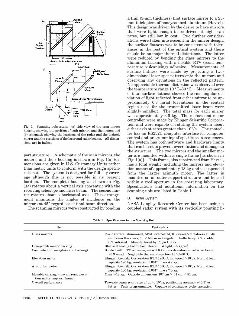
Figure 2 shows a sketch of the constructed mirror.The active part of the mirror consists of a series ofparallel copper wires spaced approximately 2.5 mmapart. The wires are of 36-gauge copper ~0.127 mmin diameter! wound over two lengths of 6.35 mm 3 20threaded brass rod. The lengths of brass rod arespaced 0.330 m apart and rigidly held by two 6.35mm 3 25.4 mm brass bars spaced 0.229 m apart.The wire was wound as a continuous length over thetwo pieces of studding and then bonded at each endby epoxy resin; one layer of wire was cut away afterthe resin had cured to leave a single reflecting plane.The complete mirror is supported by the ends of thestudding at four mounting points located just outsidethe lidar receiver beam. The physical features anddesign performance of the mirror are summarized in
Fig. 2. Schematic showing the construction of the dichroic mirror.
20 October 1999 y Vol. 38, No. 30 y APPLIED OPTICS 6385
ffmdasTtmmmttg
tmtwsaimnttwt1
utTtetbbmpbb
Table 3. Specifications and Design Performance of the Dichroic Mirror Table 4. Radiation Intensity Measurements for the Dichroic Mirrora
6
Table 3. Two-way transmission efficiency for boththe lidar and the radar is between 85% and 90%. Itcan be noted that the support frame for the dichroicmirror obscures part of the viewing aperture causingoptical transmission losses. Construction of a largerdichroic mirror would reduce these losses somewhat.Unfortunately, it would also cause the radar to beslightly further from the scanning unit, and vignett-ing losses to the radar beam would then occur.
D. Reduction of Stray Radiation and SafetyConsiderations
A small part of the radiation from the radar horn liesoutside the main ~14° wide! lobe. Scattering fromthe metal carriage and support structure could de-grade the quality of the main beam as well as consti-tute a local radiation hazard. To reduce this effect,most exposed metal surfaces that are likely to pro-duce scattering were covered with a lightweight,broadband, flexible microwave absorber. The mate-rial, MTL-72, available from Microsorb Technologies,Inc., has a thickness of 6.35 mm, and when placedagainst a metal backing has a reflectivity of approx-imately 224 dB ~0.4%! at 9 GHz. Measurements ofthe microwave radiation levels in the neighborhood ofthe radar horn showed these to be below the recom-mended maximum safe level of 10 mWycm.9 Localeye safety considerations also apply to the laser ra-diation scattered from the dichroic mirror as well asfrom the mirrors of the scanning unit. To eliminatethe possibility of eye damage to system operators, theexit beams are completely shielded within the labo-ratory.
3. Measured Performance
No quantitative measurements were made of thelosses produced in the lidar by the dichroic mirror,although atmospheric measurements show these tobe fairly small. The optical transmission numbersshown in Table 3 for the lidar are based on geometriccalculations, which are expected to determine thelosses sufficiently well.
Measurements were made of the dichroic mirrormicrowave performance before the mirror wasmounted in the lidar system. These measurements
Item Particulars
Active area 36-gauge copper wires @0.005 in. ~0.127 mm!diameter# spaced 0.1 in. ~2.5 mm! apart,parallel to the electric vector of the radarbeam. Physical size 9.0 in. ~0.229 m! 313.0 in. ~0.330 m! @projected size 9.0 in.~0.229 m! 3 9.2 in. ~0.234 m!#.
Opticaltransmission
Transmitted laser beam, 95%Received beam, 89.7%Overall, 85.2%
Radarreflection
Transmitted radar beam, 94.4%Received beam, 94.4%Overall, 89.1%
386 APPLIED OPTICS y Vol. 38, No. 30 y 20 October 1999
were of ~1! the direct unimpeded radiation intensityrom the radar horn, ~2! the intensity after reflectionrom the mirror, and ~3! the intensity behind the
irror. In the last case some diffraction of the ra-iation around the mirror may be occurring, and inll cases there are some near-field effects. The re-ults of these studies are summarized in Table 4.he accuracy of these measurements is not greaterhan 10–15% ~as is shown by the greater intensity,easured at a 50-cm range after reflection from theirror, than in the direct beam!. Nevertheless, theeasurements show the mirror reflectivity to be of
he order of 100% and that the mirror leakage is ofhe order of 5–10%, in agreement with the valuesiven in Table 3.Of more significance are measurements made of
he system performance with the lidar and radarounted together and aligned. For this purpose,
he radar cross section was scanned with a micro-ave probe mounted above the scanning unit. The
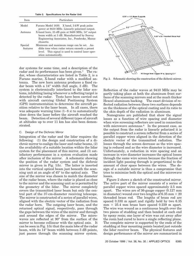
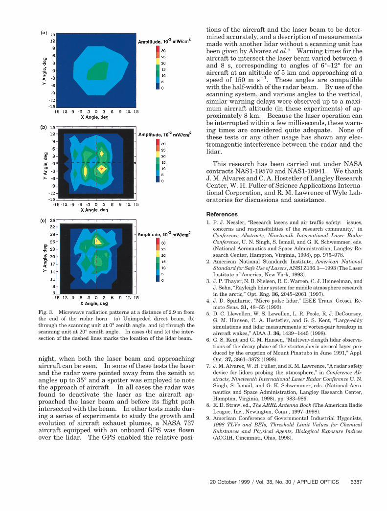
can was carried out with the exit beam both verticalnd inclined to the zenith. Results from this exper-ment are shown in Fig. 3. For practical reasons, the
aximum distance that measurements could conve-iently be made above the scanning unit was lesshan 3 m. Some field distortion is still evident athis range, most likely because of stray reflectionsithin the scanning unit itself. Figure 3~a! shows
he field distribution in the unimpeded beam; the 5 3022 mWycm2 contour is somewhat greater in angu-
lar extent than the size of the main transmitted lobe@14° total width between 3 dB ~50%! points#. Fig-
res 3~b! and 3~c! show the field distribution acrosshe beam after it passes through the scanning unit.wo zenith angles are shown, 0° and 20°, the posi-ions of the centers of the lidar beam being marked inach case. Some modification of the beam cross sec-ion has clearly taken place, the shape of the beameing squarer and hot spots appearing within theeam. The total beam energy ~;1.0 W! is approxi-ately the same in each example and in the unim-
eded beam. In both cases, the center of the laseream is close to the center of the radar field distri-ution and the 5 3 1022 mWycm2 contour is well
outside the lidar beam. Similar measurements at acloser range were made at an angle of 30°, againshowing the radar beam to surround the laser beam.The hot spots in these figures are believed to be dueto near-field effects.
Field tests have also been made of the system at
Distancefrom the
Radar Horn~cm!
DirectBeam
~mWycm2!
Reflectedfrom theMirror
~mWycm2!
LeakageBehind the
Mirror~in Wycm2!
50 4.0 4.5 0.2100 1.2 1.0 0.1
aMeasurements of field strength were made at the radar beamcenter.
night, when both the laser beam and approachingaircraft can be seen. In some of these tests the laserand the radar were pointed away from the zenith atangles up to 35° and a spotter was employed to notethe approach of aircraft. In all cases the radar wasfound to deactivate the laser as the aircraft ap-proached the laser beam and before its flight pathintersected with the beam. In other tests made dur-ing a series of experiments to study the growth andevolution of aircraft exhaust plumes, a NASA 737aircraft equipped with an onboard GPS was flownover the lidar. The GPS enabled the relative posi-
Fig. 3. Microwave radiation patterns at a distance of 2.9 m fromthe end of the radar horn. ~a! Unimpeded direct beam, ~b!through the scanning unit at 0° zenith angle, and ~c! through thescanning unit at 20° zenith angle. In cases ~b! and ~c! the inter-section of the dashed lines marks the location of the lidar beam.
tions of the aircraft and the laser beam to be deter-mined accurately, and a description of measurementsmade with another lidar without a scanning unit hasbeen given by Alvarez et al.7 Warning times for theaircraft to intersect the laser beam varied between 4and 8 s, corresponding to angles of 6°–12° for anaircraft at an altitude of 5 km and approaching at aspeed of 150 m s21. These angles are compatiblewith the half-width of the radar beam. By use of thescanning system, and various angles to the vertical,similar warning delays were observed up to a maxi-mum aircraft altitude ~in these experiments! of ap-proximately 8 km. Because the laser operation canbe interrupted within a few milliseconds, these warn-ing times are considered quite adequate. None ofthese tests or any other usage has shown any elec-tromagentic interference between the radar and thelidar.
This research has been carried out under NASAcontracts NAS1-19570 and NAS1-18941. We thankJ. M. Alvarez and C. A. Hostetler of Langley ResearchCenter, W. H. Fuller of Science Applications Interna-tional Corporation, and R. M. Lawrence of Wyle Lab-oratories for discussions and assistance.
References1. P. J. Nessler, “Research lasers and air traffic safety: issues,
concerns and responsibilities of the research community,” inConference Abstracts, Nineteenth International Laser RadarConference, U. N. Singh, S. Ismail, and G. K. Schwemmer, eds.~National Aeronautics and Space Administration, Langley Re-search Center, Hampton, Virginia, 1998!, pp. 975–978.
2. American National Standards Institute, American NationalStandard for Safe Use of Lasers, ANSI Z136.1—1993 ~The LaserInstitute of America, New York, 1993!.
3. J. P. Thayer, N. B. Nielsen, R. E. Warren, C. J. Heinselman, andJ. Sohn, “Rayleigh lidar system for middle atmosphere researchin the arctic,” Opt. Eng. 36, 2045–2061 ~1997!.
4. J. D. Spinhirne, “Micro pulse lidar,” IEEE Trans. Geosci. Re-mote Sens. 31, 48–55 ~1993!.
5. D. C. Llewellen, W. S. Lewellen, L. R. Poole, R. J. DeCoursey,G. M. Hansen, C. A. Hostetler, and G. S. Kent, “Large-eddysimulations and lidar measurements of vortex-pair breakup inaircraft wakes,” AIAA J. 36, 1439–1445 ~1998!.
6. G. S. Kent and G. M. Hansen, “Multiwavelength lidar observa-tions of the decay phase of the stratospheric aerosol layer pro-duced by the eruption of Mount Pinatubo in June 1991,” Appl.Opt. 37, 3861–3872 ~1998!.
7. J. M. Alvarez, W. H. Fuller, and R. M. Lawrence, “A radar safetydevice for lidars probing the atmosphere,” in Conference Ab-stracts, Nineteenth International Laser Radar Conference U. N.Singh, S. Ismail, and G. K. Schwemmer, eds. ~National Aero-nautics and Space Administration, Langley Research Center,Hampton, Virginia, 1998!, pp. 983–986.
8. R. D. Straw, ed., The ARRL Antenna Book ~The American RadioLeague, Inc., Newington, Conn., 1997–1998!.
9. American Conference of Governmental Industrial Hygenists,1998 TLVs and BEIs, Threshold Limit Values for ChemicalSubstances and Physical Agents, Biological Exposure Indices~ACGIH, Cincinnati, Ohio, 1998!.
20 October 1999 y Vol. 38, No. 30 y APPLIED OPTICS 6387