Embed Size (px)
Citation preview
Aerosol Neutral izers
Model 3936 Scanning Mobility
Particle Sizer™ (SMPS™) Spectrometer
Operation and Service Manual
P/N 1933796, Revision P June 2010


Model 3936 Scanning Mobility Particle Sizer™ (SMPS™) Spectrometer Operation and Service Manual
SMPS™ Spectrometer Overview
1
Unpacking the SMPS™ Spectrometer
2
Setting Up SMPS™ Hardware
3
Operating SMPS™ Hardware
4
Maintaining and Troubleshooting the SMPS™ Spectrometer
5
Service 6
Appendixes and Index
vi
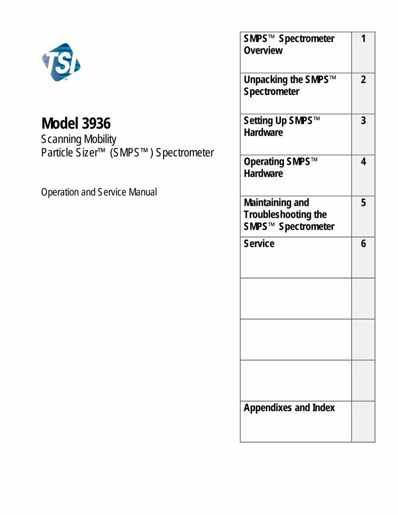
Manual H is tory
The following is a history of the Model 3936 Scanning Mobility Particle Sizer™ (SMPS™) Spectrometer Operation and Service Manual, P/N 1933796.
Revision Date First printing March 1999 Final April 1999 A November 1999 B April 2000 C May 2000 D July 2000 E July 18, 2000 F February 2001 G August 2002 H September 2003 I June 2004 J February 2005 K December 2005 L October 2006 M April 2008 N March 2009 P June 2010
vii
Warranty
Part Number 1933796 / Revision P / June 2010
Copyright ©TSI Incorporated / 1999–2010 / All rights reserved
Address TSI Incorporated / 500 Cardigan Road / Shoreview, MN 55126 / USA
Fax No. (651) 490-3824
E-mail Address [email protected]
Limitation of Warranty and Liability (effective July 2000)
Seller warrants the goods sold hereunder, under normal use and service as described in the operator's manual, shall be free from defects in workmanship and material for twelve (12) months, or the length of time specified in the operator's manual, from the date of shipment to the customer. This warranty period is inclusive of any statutory warranty. This limited warranty is subject to the following exclusions:
a. Hot-wire or hot-film sensors used with research anemometers, and certain other components when indicated in specifications, are warranted for 90 days from the date of shipment.
b. Parts repaired or replaced as a result of repair services are warranted to be free from defects in workmanship and material, under normal use, for 90 days from the date of shipment.
c. Seller does not provide any warranty on finished goods manufactured by others or on any fuses, batteries or other consumable materials. Only the original manufacturer's warranty applies.
d. Unless specifically authorized in a separate writing by Seller, Seller makes no warranty with respect to, and shall have no liability in connection with, goods which are incorporated into other products or equipment, or which are modified by any person other than Seller.
The foregoing is IN LIEU OF all other warranties and is subject to the LIMITATIONS stated herein. NO OTHER EXPRESS OR IMPLIED WARRANTY OF FITNESS FOR PARTICULAR PURPOSE OR MERCHANTABILITY IS MADE.
TO THE EXTENT PERMITTED BY LAW, THE EXCLUSIVE REMEDY OF THE USER OR BUYER, AND THE LIMIT OF SELLER'S LIABILITY FOR ANY AND ALL LOSSES, INJURIES, OR DAMAGES CONCERNING THE GOODS (INCLUDING CLAIMS BASED ON CONTRACT, NEGLIGENCE, TORT, STRICT LIABILITY OR OTHERWISE) SHALL BE THE RETURN OF GOODS TO SELLER AND THE REFUND OF THE PURCHASE PRICE, OR, AT THE OPTION OF SELLER, THE REPAIR OR REPLACEMENT OF THE GOODS. IN NO EVENT SHALL SELLER BE LIABLE FOR ANY SPECIAL, CONSEQUENTIAL OR INCIDENTAL DAMAGES. SELLER SHALL NOT BE RESPONSIBLE FOR INSTALLATION, DISMANTLING OR REINSTALLATION COSTS OR CHARGES. No Action, regardless of form, may be brought against Seller more than 12 months after a cause of action has accrued. The goods returned under warranty to Seller's factory shall be at Buyer's risk of loss, and will be returned, if at all, at Seller's risk of loss.
Buyer and all users are deemed to have accepted this LIMITATION OF WARRANTY AND LIABILITY, which contains the complete and exclusive limited warranty of Seller. This LIMITATION OF WARRANTY AND LIABILITY may not be amended, modified or its terms waived, except by writing signed by an Officer of Seller.
Service Policy Knowing that inoperative or defective instruments are as detrimental to TSI as they are to our customers, our service policy is designed to give prompt attention to any problems. If any mal-function is discovered, please contact your nearest sales office or representative, or call TSI at 1-800-874-2811 (USA) or (651) 490-2811.
viii Model 3936 Scanning Mobility Particle SizerTM (SMPSTM) Spectrometer
Software License (effective March 1999)
This is a legal agreement between you, the end user, and TSI Incorporated. BY INSTALLING THE SOFTWARE, YOU ARE AGREEING TO BE BOUND BY THE TERMS OF THIS AGREEMENT. IF YOU DO NOT AGREE TO THE TERMS OF THIS AGREEMENT, PROMPTLY RETURN THE UNOPENED PACKAGE AND THE ACCOMPANYING ITEMS (including written materials and binders or other containers) to TSI for a full refund. TSI SOFTWARE TERMS
1. GRANT OF LICENSE. TSI grants to you the right to use one copy of the enclosed TSI software program (the “SOFTWARE”), on a single computer. You may not network the SOFTWARE or otherwise use it on more than one computer or computer terminal at the same time.
2. COPYRIGHT. The SOFTWARE is owned by TSI and is protected by United States copyright laws and international treaty provisions. Therefore, you must treat the SOFTWARE like any other copyrighted material (e.g., a book or musical recording) except that you may either (a) make one copy of the SOFTWARE solely for backup or archival purposes, or (b) transfer the SOFTWARE to a single hard disk provided you keep the original solely for backup or archival purposes.
3. OTHER RESTRICTIONS. You may not rent or lease the SOFTWARE, but you may transfer the SOFTWARE and accompanying written material on a permanent basis, provided you retain no copies and the recipient agrees to the terms of this Agreement. You may not reverse-engineer, decompile, or disassemble the SOFTWARE.
4. DUAL MEDIA SOFTWARE. If the SOFTWARE package contains multiple types of media, then you may use only the media appropriate for your single-user computer. You may not use the other media on another computer or loan, rent, lease, or transfer them to another user except as part of the permanent transfer (as provided above) of all SOFTWARE and written material.
5. U.S. GOVERNMENT RESTRICTED RIGHTS. The SOFTWARE and documentation are provided with RESTRICTED RIGHTS. Use, duplication, or disclosure by the Government is subject to the restrictions set forth in the “Rights in Technical Data and Computer Software” Clause at 252.227-7013 and the “Commercial Computer Software - Restricted Rights” clause at 52.227-19.
6. LIMITED WARRANTY. TSI warrants that the SOFTWARE will perform substantially in accordance with the accompanying written materials for a period of ninety (90) days from the date of receipt.
7. CUSTOMER REMEDIES. TSI’s entire liability and your exclusive remedy shall be, at TSI’s option, either (a) return of the price paid or (b) repair or replacement of the SOFTWARE that does not meet this Limited Warranty and which is returned to TSI with proof of payment. This Limited Warranty is void if failure of the SOFTWARE has resulted from accident, abuse, or misapplication. Any replacement SOFTWARE will be warranted for the remainder of the original warranty period or thirty (30) days, whichever is longer.
8. NO OTHER WARRANTIES. TSI disclaims all other warranties, either express or implied, including, but not limited to implied warranties of merchantability and fitness for a particular purpose, with regard to the SOFTWARE and the accompanying written materials.
9. NO LIABILTY FOR CONSEQUENTIAL DAMAGES. In no event shall TSI be liable for any damages whatsoever (including, without limitation, special, incidental, consequential or indirect damages for personal injury, loss of business profits, business interruption, loss of information or any other pecuniary loss) arising out of the use of, or inability to use, this SOFTWARE.
Trademarks Microsoft is a registered trademark of Microsoft Corporation. Windows is a trademark of Microsoft Corporation. IBM is a registered trademark of International Business Machines Corporation. Scanning Mobility Particle SizerTM and SMPSTM are trademarks of TSI Incorporated. Aerosol Instrument Manager® is a registered trademark of TSI Incorporated.
Acknowledgments TSI Incorporated acknowledges the significant contributions of Richard C. Flagan of the California Institute of Technology and Kevin Horton of AEA Technology for their research and support in developing Scanning Mobility Particle SizerTM (SMPSTM) system software.
ix
Safety
This section gives instructions to promote safe and proper operation of the Model 3936 Scanning Mobility Particle Sizer™ (SMPS™) Spectrometer, samples of warnings found in this manual, and information on labels attached to system instruments.
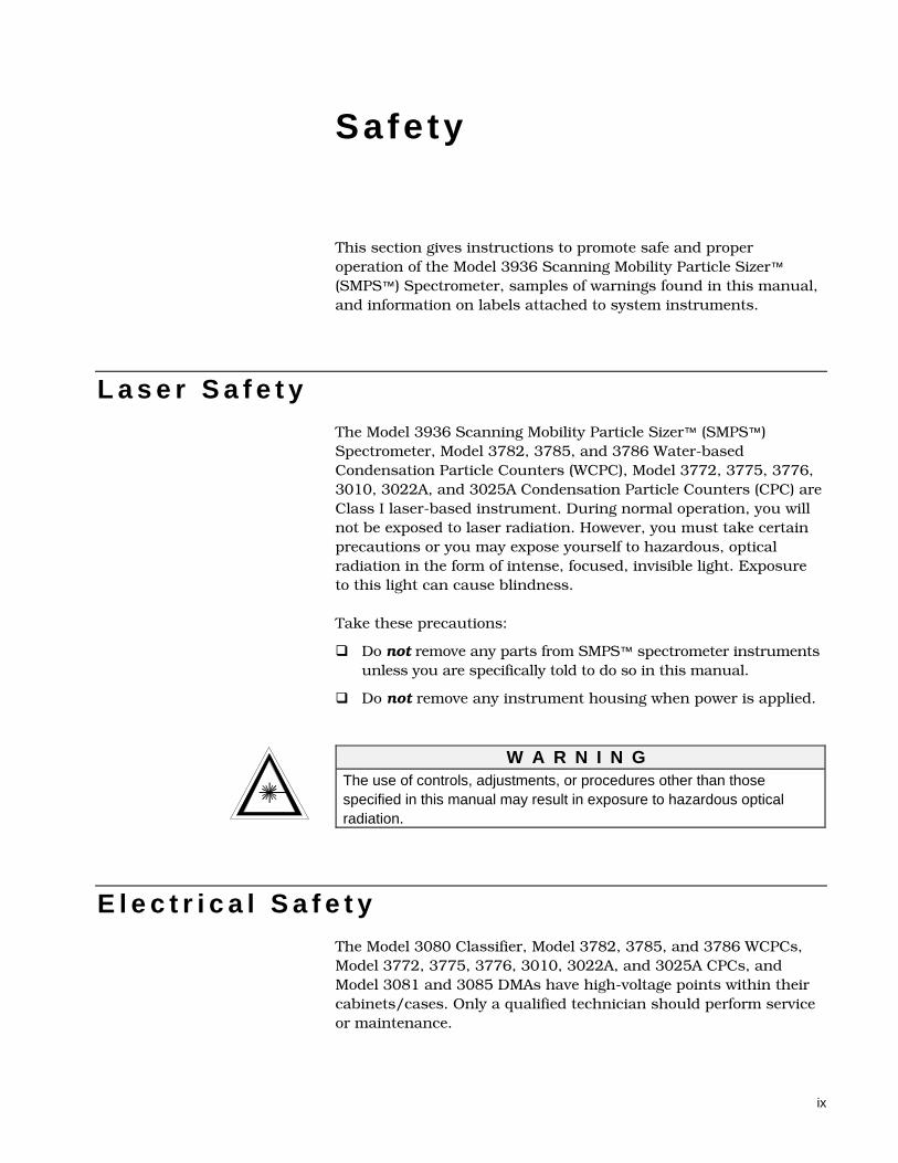
L a s e r S a f e t y The Model 3936 Scanning Mobility Particle Sizer™ (SMPS™) Spectrometer, Model 3782, 3785, and 3786 Water-based Condensation Particle Counters (WCPC), Model 3772, 3775, 3776, 3010, 3022A, and 3025A Condensation Particle Counters (CPC) are Class I laser-based instrument. During normal operation, you will not be exposed to laser radiation. However, you must take certain precautions or you may expose yourself to hazardous, optical radiation in the form of intense, focused, invisible light. Exposure to this light can cause blindness. Take these precautions:
Do not remove any parts from SMPS™ spectrometer instruments unless you are specifically told to do so in this manual.
Do not remove any instrument housing when power is applied.
W A R N I N G
The use of controls, adjustments, or procedures other than those specified in this manual may result in exposure to hazardous optical radiation.
E l e c t r i c a l S a f e t y The Model 3080 Classifier, Model 3782, 3785, and 3786 WCPCs, Model 3772, 3775, 3776, 3010, 3022A, and 3025A CPCs, and Model 3081 and 3085 DMAs have high-voltage points within their cabinets/cases. Only a qualified technician should perform service or maintenance.

x Model 3936 Scanning Mobility Particle SizerTM (SMPSTM) Spectrometer
W A R N I N G High voltage is accessible in several locations within these instruments. Make sure you unplug the power source before removing the cover or performing maintenance procedures. Don’t apply power to the Model 3080 Classifier unless you have a DMA high-voltage cord connected and the DMA properly grounded through the base plate.
C h e m i c a l S a f e t y
The Model 3772, 3775, 3776, 3010, 3022A, and 3025A CPCs use n-butyl alcohol (butanol) as a working fluid. Butanol is flammable. Butanol is also toxic if inhaled. Refer to a material safety data sheet on butanol and take these precautions:
Use butanol only in a well-ventilated area.
Butanol vapor is identified by its characteristically strong odor and can easily be detected. If you smell butanol and develop a headache, or feel faint or nauseous, leave the area at once. Ventilate the area before returning.
!
C a u t i o n Butanol is flammable. Butanol is also potentially toxic if inhaled. Use butanol only in a well-ventilated area. If you smell butanol and develop a headache, or feel faint or nauseous, leave the area at once. Ventilate the area before returning.
!
W A R N I N G Although the CPC is appropriate for monitoring inert process gases such as nitrogen or argon, it should not be used with hazardous gases such as hydrogen or oxygen. Using the CPC with hazardous gases may cause injury to personnel and damage to equipment.
Safety xi
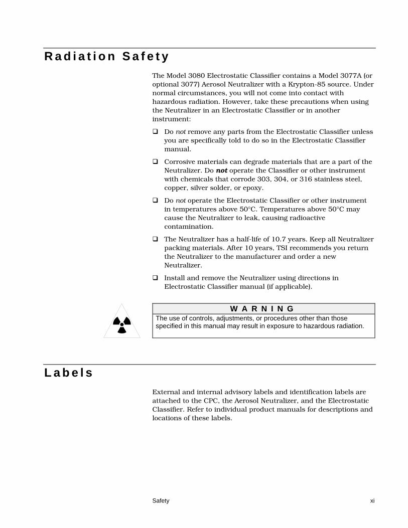
R a d i a t i o n S a f e t y The Model 3080 Electrostatic Classifier contains a Model 3077A (or optional 3077) Aerosol Neutralizer with a Krypton-85 source. Under normal circumstances, you will not come into contact with hazardous radiation. However, take these precautions when using the Neutralizer in an Electrostatic Classifier or in another instrument:
Do not remove any parts from the Electrostatic Classifier unless you are specifically told to do so in the Electrostatic Classifier manual.
Corrosive materials can degrade materials that are a part of the Neutralizer. Do not operate the Classifier or other instrument with chemicals that corrode 303, 304, or 316 stainless steel, copper, silver solder, or epoxy.
Do not operate the Electrostatic Classifier or other instrument in temperatures above 50°C. Temperatures above 50°C may cause the Neutralizer to leak, causing radioactive contamination.
The Neutralizer has a half-life of 10.7 years. Keep all Neutralizer packing materials. After 10 years, TSI recommends you return the Neutralizer to the manufacturer and order a new Neutralizer.
Install and remove the Neutralizer using directions in Electrostatic Classifier manual (if applicable).
W A R N I N G The use of controls, adjustments, or procedures other than those specified in this manual may result in exposure to hazardous radiation.
L a b e l s External and internal advisory labels and identification labels are attached to the CPC, the Aerosol Neutralizer, and the Electrostatic Classifier. Refer to individual product manuals for descriptions and locations of these labels.

xii Model 3936 Scanning Mobility Particle SizerTM (SMPSTM) Spectrometer
(This page intentionally left blank)
xiii
Contents
Manual History ........................................................................................... vi
Warranty .................................................................................................... vii
Safety .......................................................................................................... ix Laser Safety .......................................................................................... ix Electrical Safety .................................................................................... ix Chemical Safety ..................................................................................... x Radiation Safety .................................................................................... xi Labels .................................................................................................... xi
About This Manual ................................................................................. xvii Purpose ............................................................................................... xvii Related Product Literature .................................................................. xvii Submitting Comments ........................................................................ xviii
CHAPTER 1 SMPS™ Spectrometer Overview ...................................... 1-1 Product Description ............................................................................. 1-1 How the System Operates .................................................................. 1-2
CHAPTER 2 Unpacking the SMPS™ Spectrometer ............................. 2-1 Packing Lists ....................................................................................... 2-1 Unpacking Instructions........................................................................ 2-2
CHAPTER 3 Setting Up SMPS Hardware .............................................. 3-1 Cabling Connections ........................................................................... 3-1
Connections to the Electrostatic Classifier ...................................... 3-1 Cabling the CPC to the Computer ................................................... 3-2
Applying Power Sequence .................................................................. 3-3 Recommended Mode of Operation ..................................................... 3-4
Underpressure and Overpressure Modes ....................................... 3-4 Typical Mode of Operation ............................................................... 3-4
Plumbing Connections ........................................................................ 3-4 Connecting the Model 3772 or 3010 CPC ....................................... 3-4 Connecting the Model 3775 or 3022A CPC .................................... 3-8 Connecting the Model 3776 or 3025A UCPC ................................ 3-10 Connecting the Model 3782, 3785, or 3786 WCPC ...................... 3-14
CHAPTER 4 Operating SMPS™ Hardware............................................ 4-1 Before You Begin ................................................................................ 4-1 Selecting Flow Rates .......................................................................... 4-2
Impactor as a Flowmeter ................................................................. 4-5 Setting Flow Rates .............................................................................. 4-6
Underpressure Mode ....................................................................... 4-6 Overpressure Mode ......................................................................... 4-6
SMPS Spectrometer Check ................................................................ 4-6
xiv Model 3936 Scanning Mobility Particle SizerTM (SMPSTM) Spectrometer
CHAPTER 5 Maintaining and Troubleshooting the SMPS™ Spectrometer .............................................................................. 5-1
Maintenance Recommendations ........................................................ 5-1 Troubleshooting .................................................................................. 5-2
Problems and Solutions ................................................................... 5-2 Testing for Leaks ............................................................................. 5-3
CHAPTER 6 Service ................................................................................ 6-1 Technical Contacts ............................................................................. 6-1 Returning the SMPS™ Spectrometer for Service .............................. 6-2
APPENDIX A Specifications .................................................................. A-1
APPENDIX B Theory of Operation ........................................................ B-1 Introduction ........................................................................................ B-1 History ................................................................................................ B-1 Impaction Theory and Operation ....................................................... B-2 Electrostatic Classifier ....................................................................... B-4 Charging Theory ................................................................................ B-7 Particle Mobility Theory ................................................................... B-10 Condensation Particle Counter ........................................................ B-13
CPC Theory .................................................................................. B-13 Particle Counting .......................................................................... B-15 Operating at Higher Concentrations ............................................. B-16
The Data Measurement Process ..................................................... B-17 References ...................................................................................... B-19
APPENDIX C Calculation of the Geometric Mean and Geometric Standard Deviation for Number, Surface, and Volume Distributions .............................................................................. C-1
APPENDIX D Communication between Aerosol Instrument Manager® Software and the Electrostatic Classifier Model 3080 ................................................................................. D-1
Index
Reader’s Comments
F i g u r e s 1-1 SMPS Spectrometer Shown with a Model 3085 Nano DMA
and Model 3786 UWCPC ............................................................. 1-1 3-1 Model 3772 CPC with Nano DMA .................................................... 3-5 3-2 Model 3010 CPC with Nano DMA .................................................... 3-6 3-3 Model 3772 CPC with Long DMA ..................................................... 3-7 3-4 Model 3010 CPC with Long DMA ..................................................... 3-7 3-5 Model 3775 CPC with Nano DMA .................................................... 3-8 3-6 Model 3022A CPC with Nano DMA .................................................. 3-9 3-7 Model 3775 CPC with Long DMA ................................................... 3-10
Contents xv
3-8 Model 3022A CPC with Long DMA ................................................. 3-10 3-9 Model 3776 UCPC with Nano DMA ................................................ 3-11 3-10 Model 3025A UCPC with Nano DMA .............................................. 3-12 3-11 Model 3776 CPC with Long DMA ................................................... 3-13 3-12 Model 3025A UCPC with Long DMA .............................................. 3-13 3-13 Model 3782, 3785, or 3786 WCPC with Nano DMA ....................... 3-14 3-14 Model 3782, 3785, or 3786 WCPC with Long DMA ....................... 3-15 4-1 Classifier LCD Display ...................................................................... 4-1 4-2 Schematic Flow Diagram of the Classifier with Long DMA ............... 4-2 4-3 Schematic Flow Diagram of the Classifier with Nano DMA .............. 4-3 B-1 Classifier Shown with Impactor Installed on Inlet ............................ B-3 B-2 Cross-Sectional View of an Inertial Impactor [Hinds,
1982] ............................................................................................ B-3 B-3 Flow Schematic for the Electrostatic Classifier with
Long LDMA .................................................................................. B-5 B-4 Flow Schematic for the Electrostatic Classifier with Nano
DMA ............................................................................................. B-6 B-5 Bipolar Particle Charge Distribution in Air [Wiedensohler
and Fissan, 1988] ........................................................................ B-7 B-6 Center Rod Voltage as a Function of Particle Diameter
for Normal Operating Conditions of the Long DMA .................. B-12 B-7 Graph of the CPC Counting Efficiency Curves .............................. B-14 B-8 Transfer Function of the Electrostatic Classifier
[Knutson and Whitby, 1975] ...................................................... B-18
T a b l e s 2-1 Main Components of the SMPS Spectrometer ................................. 2-1 2-2 Model 390087 Interface Pack Packing List ....................................... 2-2 2-3 Model 1035900 Inlet Impactor Packing List ...................................... 2-2
4-1 Recommended Operating Parameters ............................................. 4-4 4-2 Impactor ∆P and 50% Cut Size vs. Flow Rate .................................. 4-5
5-1 Maintenance Schedule ...................................................................... 5-1 5-2 SMPS Spectrometer Problems and Solutions .................................. 5-2
A-1 SMPS Specifications ....................................................................... A-1
B-1 Midpoint Mobilities, Midpoint Particle Diameters, and Fraction of Total Particle Concentration that Carries +1, +2, +3, +4, +5, and +6 Elementary Charges as a Function of Mobility ............... B-8
B-2 Coefficients for Equation B-2 ........................................................... B-9 B-3 Coincidence Levels ........................................................................ B-16

xvi Model 3936 Scanning Mobility Particle SizerTM (SMPSTM) Spectrometer
(This page intentionally left blank)
xvii
About This Manual
P u r p o s e This is an installation and operations manual for the Model 3936 Scanning Mobility Particle Sizer™ (SMPS™) Spectrometer.
R e l a t e d P r o d u c t L i t e r a t u r e The following TSI product manuals may be of use as references to the SMPS™ spectrometer.
Aerosol Instrument Manager® Software for SMPS Instruction Manual (part number 1930104) TSI Incorporated
Model 3080 Electrostatic Classifier Instruction Manual (part number 1933792) TSI Incorporated
Model 3772/3771 Condensation Particle Counter Operation and Service Manual (part number 1980529) TSI Incorporated
Model 3775 Condensation Particle Counter Operation and Service Manual (part number 1980527) TSI Incorporated
Model 3776 Ultrafine Condensation Particle Counter Operation and Service Manual (part number 1980522) TSI Incorporated
Model 3782 Water-based Condensation Particle Counter Operation and Service Manual (part number 1930073) TSI Incorporated
Model 3785 Water-based Condensation Particle Counter Operation and Service Manual (part number 1933001) TSI Incorporated
Model 3786 Ultrafine Water-based Condensation Particle Counter Operation and Service Manual (part number 1930072) TSI Incorporated
Model 3010 Condensation Particle Counter Instruction Manual (part number 1933010) TSI Incorporated

xviii Model 3936 Scanning Mobility Particle SizerTM (SMPSTM) Spectrometer
Model 3022A Condensation Particle Counter Instruction Manual (part number 1933763) TSI Incorporated
Model 3025A Ultrafine Condensation Particle Counter Instruction Manual (part number 1933762) TSI Incorporated
S u b m i t t i n g C o m m e n t s TSI values your comments and suggestions on this manual. Please use the comment sheet on the last page of this manual to send us your opinion on the manual’s usability, to suggest specific improvements, or to report any technical errors. If the comment sheet has already been used, please mail, fax or email your comments on another sheet of paper to:
TSI Incorporated 500 Cardigan Road Shoreview, MN 55126 USA Fax: (651) 490-3824 Email: [email protected]
1-1
C H A P T E R 1 SMPS™ Spectrometer Overv iew
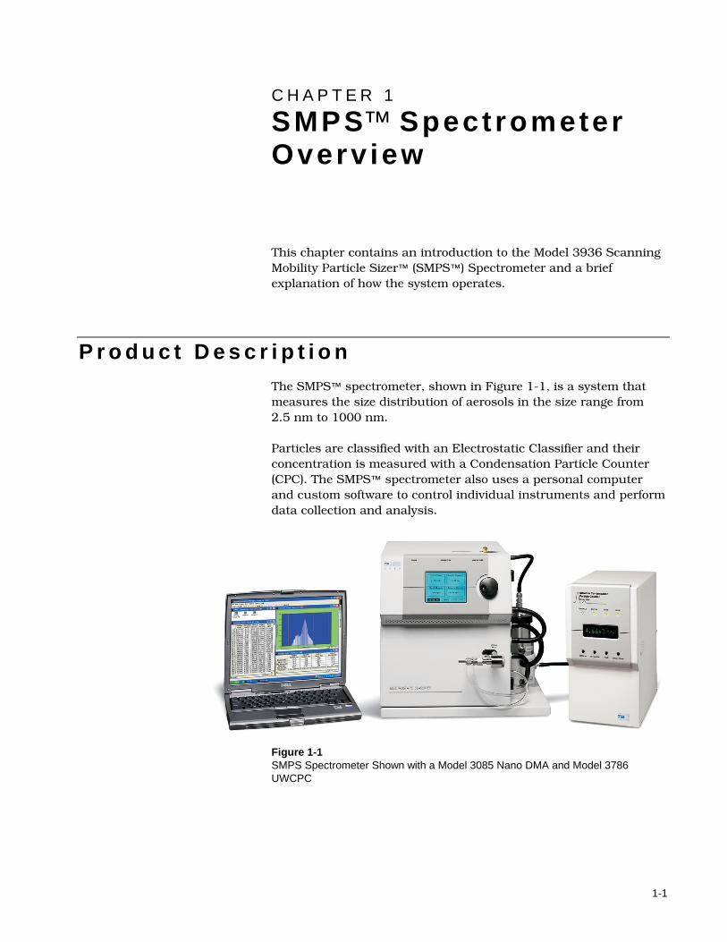
This chapter contains an introduction to the Model 3936 Scanning Mobility Particle Sizer™ (SMPS™) Spectrometer and a brief explanation of how the system operates.
P r o d u c t D e s c r i p t i o n The SMPS™ spectrometer, shown in Figure 1-1, is a system that measures the size distribution of aerosols in the size range from 2.5 nm to 1000 nm. Particles are classified with an Electrostatic Classifier and their concentration is measured with a Condensation Particle Counter (CPC). The SMPS™ spectrometer also uses a personal computer and custom software to control individual instruments and perform data collection and analysis.
Figure 1-1 SMPS Spectrometer Shown with a Model 3085 Nano DMA and Model 3786 UWCPC
1-2 Model 3936 Scanning Mobility Particle SizerTM (SMPSTM) Spectrometer
The SMPS™ spectrometer can be used in applications like these:
Basic aerosol research
Nanometer-particle research
Atmospheric aerosol studies
Pollution studies
Smog chamber evaluations
Aerosol dynamics
Engine exhaust and combustion studies
Materials synthesis
Filter efficiency testing
Nucleation/condensation studies
Inhalation toxicology studies
Characterizing sprays, powders, and other generated aerosols
Detecting small changes in rapidly changing aerosol systems
Mobile aerosol studies
H o w t h e S y s t e m O p e r a t e s The Model 3936 SMPS™ spectrometer measures the size distribution of particles using an electrical mobility detection technique. The SMPS spectrometer uses a bipolar charger in the Electrostatic Classifier to charge the particles to a known charge distribution. The particles are then classified according to their ability to traverse an electrical field, and counted with a Model 3782, 3785, or 3786 Water-based Condensation Particle Counter (WCPC), 3772, 3775, 3776, 3010, 3022A, or 3025A Condensation Particle Counter (CPC). The entire system is automated. Data analysis is performed using a computer system with customized software. The Aerosol Instrument Manager® Software for SMPS™ spectrometer collects and stores sample data. Data can be displayed in graphs and tables and can be exported to other applications. For a detailed theory of operation, refer to Appendix B.
2-1
C H A P T E R 2 Unpacking the SMPS™ Spectrometer
Use the information in this chapter to unpack the various components of the 3936 Scanning Mobility Particle Sizer™ (SMPS™) Spectrometer.
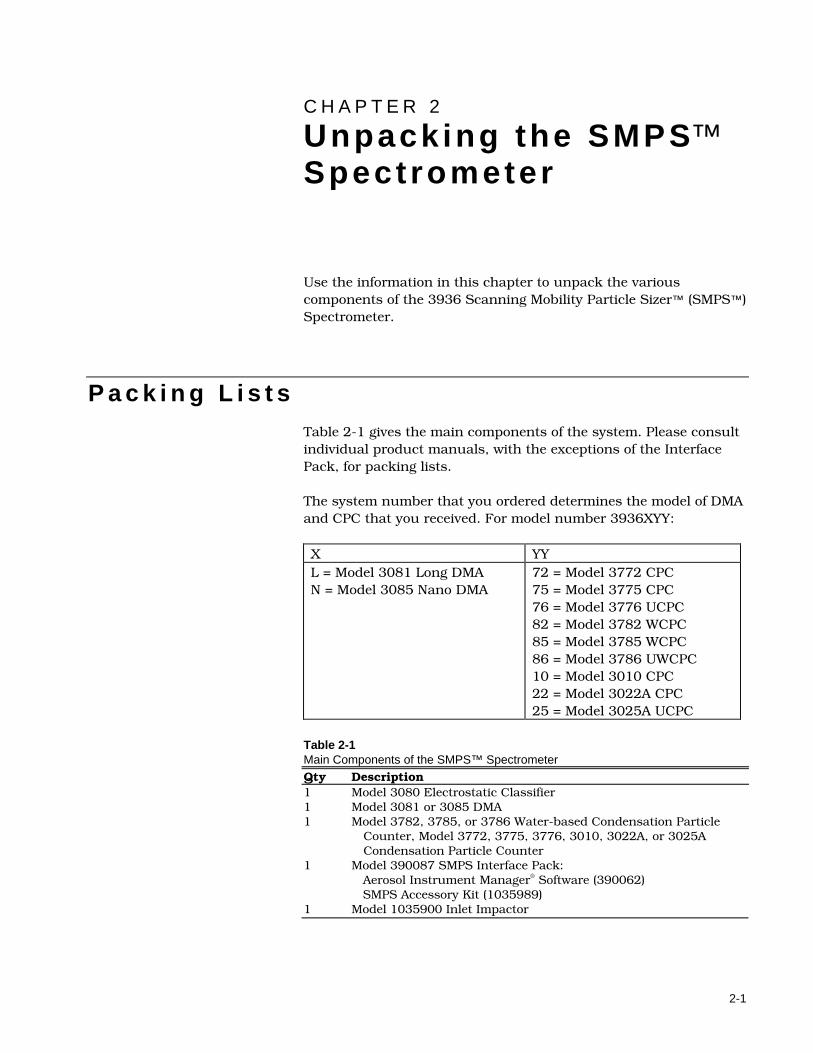
P a c k i n g L i s t s Table 2-1 gives the main components of the system. Please consult individual product manuals, with the exceptions of the Interface Pack, for packing lists. The system number that you ordered determines the model of DMA and CPC that you received. For model number 3936XYY: X YY L = Model 3081 Long DMA N = Model 3085 Nano DMA
72 = Model 3772 CPC 75 = Model 3775 CPC 76 = Model 3776 UCPC 82 = Model 3782 WCPC 85 = Model 3785 WCPC 86 = Model 3786 UWCPC 10 = Model 3010 CPC 22 = Model 3022A CPC 25 = Model 3025A UCPC
Table 2-1 Main Components of the SMPS™ Spectrometer Qty Description 1 Model 3080 Electrostatic Classifier 1 Model 3081 or 3085 DMA 1 Model 3782, 3785, or 3786 Water-based Condensation Particle
Counter, Model 3772, 3775, 3776, 3010, 3022A, or 3025A Condensation Particle Counter
1 Model 390087 SMPS Interface Pack: Aerosol Instrument Manager® Software (390062) SMPS Accessory Kit (1035989)
1 Model 1035900 Inlet Impactor
2-2 Model 3936 Scanning Mobility Particle SizerTM (SMPSTM) Spectrometer
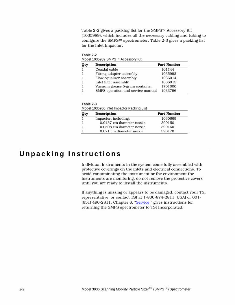
Table 2-2 gives a packing list for the SMPS™ Accessory Kit (1035989), which includes all the necessary cabling and tubing to configure the SMPS™ spectrometer. Table 2-3 gives a packing list for the Inlet Impactor. Table 2-2 Model 1035989 SMPS™ Accessory Kit
Qty Description Part Number 1 Coaxial cable 101144 1 Fitting adapter assembly 1035992 1 Flow equalizer assembly 1036014 1 Inlet filter assembly 1036015 1 Vacuum grease 5-gram container 1701000 1 SMPS operation and service manual 1933796
Table 2-3 Model 1035900 Inlet Impactor Packing List
Qty Description Part Number 1 Impactor, including: 1030669 1 0.0457 cm diameter nozzle 390150 1 0.0508 cm diameter nozzle 390160 1 0.071 cm diameter nozzle 390170
U n p a c k i n g I n s t r u c t i o n s Individual instruments in the system come fully assembled with protective coverings on the inlets and electrical connections. To avoid contaminating the instrument or the environment the instruments are monitoring, do not remove the protective covers until you are ready to install the instruments. If anything is missing or appears to be damaged, contact your TSI representative, or contact TSI at 1-800-874-2811 (USA) or 001-(651) 490-2811. Chapter 6, “Service,” gives instructions for returning the SMPS spectrometer to TSI Incorporated.
3-1
C H A P T E R 3 Set t ing Up SMPS Hardware
This chapter gives information you need to set up the Model 3936 Scanning Mobility Particle Sizer™ (SMPS™) Spectrometer hardware:
Cabling connections
A sequence to apply power to the different instruments
Plumbing arrangements for each combination of Condensation Particle Counter (CPC) and Differential Mobility Analyzer (DMA)
After you set up the system hardware, use the information in Chapter 4 to set flow rates. Refer to the Aerosol Instrument Manager® Software for SMPS™ Instruction Manual to install and operate the system software. Note: Refer to individual component manuals for the following:
The Electrostatic Classifier instruction manual contains power requirements and information on installing each DMA and a Neutralizer.
CPC instruction manuals contain power requirements and information on mounting a fill-bottle bracket.
C a b l i n g C o n n e c t i o n s This section contains information for making power and system cabling connections.
Connections to the Electrostatic Classifier Use the information in this subsection to connect BNC and power cables to the Electrostatic Classifier.
3-2 Model 3936 Scanning Mobility Particle SizerTM (SMPSTM) Spectrometer
BNC Cable
Connect the BNC cable between the CPC and the Electrostatic Classifier to allow the CPC to set the voltage on the center rod of the Model 3081 or 3085 DMA.
1. Connect one end of the BNC cable to the connector labeled “BNC” (Model 3010), “Analog Output” (Model 3022A, 3025A, 3782, 3785, or 3786), or “DMA/Analog Output” (Model 3772, 3775, and 3776).
2. Connect the other end of the BNC cable to the BNC connector labeled “Analog Input” on the back panel of the Electrostatic Classifier.
Serial Cable or USB to Serial Cable
Aerosol Instrument Manager® software version 8.2 has the ability to communicate with TSI Model 3080 Electrostatic Classifier. If you wish to use this capability, connect an RS-232 serial cable between a serial port on the computer and the serial port on the Electrostatic Classifier. If the computer does not have an available serial port, use a USB to serial adapter cable. Power Cable
The On/Off switch is on the back panel of the Model 3080 next to the power cord connector. Make sure the On/Off switch on the Electrostatic Classifier is off. Plug the power cord into the back panel of the Classifier and into the AC power source.
Cabling the CPC to the Computer Locate COM port on the back panel of the CPC. Connect the serial interface cable from the computer serial port to the COM port on the CPC. For the 3782, 3785, 3786 WCPC, 3772, 3775, or 3776 CPC, USB cables can also be used to connect the computer to the instrument. Refer to the individual CPC manual for detailed instructions.
!
C a u t i o n When connecting any model of CPC, use the RS-232 or USB cable supplied with the CPC.
Setting Up SMPS Hardware 3-3
!
N o t e When connecting the RS-232 or USB cable, make sure you connect the cable from the computer to the CPC. The SMPS™ spectrometer requires the synchronization between classifier voltage and particle counts that the CPC provides. If using Aerosol Instrument Manager® software version 8.2 or later, an optional connection between the computer and the Model 3080 classifier can be made using an RS-232 cable.
A p p l y i n g P o w e r S e q u e n c e This section contains the sequence for applying power to the instruments in the SMPS™ spectrometer. If you apply power to the instruments at this stage in the setup process, the CPC and Electrostatic Classifier will be ready to operate when you select and set flow rates according to Chapter 4.
Refer to the Model 3010 Condensation Particle Counter Instruction Manual for information on DIP switch settings; refer to a Model 3022A or 3025A CPC instruction manual for information on using the configuration mode.
1. Before you apply power, set the analog output in the Model 3010, 3022A, or 3025A CPC to HOST. If you do not set the analog output to HOST, there may be communications problems between the computer and the CPC. Typically, analog outputs of the 3010, 3022A, and 3025A CPCs are set to HOST at TSI. For a Model 3772, 3775, or 3776 CPC, there is no need to set the HOST mode if Aerosol Instrument Manager Software is used to collect data. If custom software is used, you may need to set the mode using SCM firmware command. Refer to individual instrument manual on how to get information on firmware commands. There is no need to set the Model 3782, 3785, or 3786 WCPC to HOST mode because the HOST mode is the only mode for the WCPCs.
For the Model 3010 CPC, set the analog output to HOST using DIP switches 6, 7, and 8 on the back panel of the instrument.
For a Model 3022A or 3025A CPC, use the configuration mode to set the output by pressing function buttons in response to questions posed on the display.
2. Before you apply power to the Classifier, follow the procedures in the Classifier manual for installing the DMA, DMA plumbing, and impactor inlet.
3. Apply power to the Classifier by switching Power to the On position. The Power switch is located on the back panel of the Model 3080 Classifier.
3-4 Model 3936 Scanning Mobility Particle SizerTM (SMPSTM) Spectrometer
4. On the front panel of the Classifier, set the control mode (lower-left box on display) to “Analog Ctrl.”
5. Apply power to the CPC. For Model 3772, 3775, 3776, 3022A, 3025A CPCs, 3782, 3785, and 3786 WCPCs, ensure the internal CPC pump is off and the green Pump LED on the front panel is not lit.
6. Continue setting up the SMPS spectrometer by connecting the CPC as described in the next section in this chapter.
R e c o m m e n d e d M o d e o f O p e r a t i o n
Underpressure and Overpressure Modes In the past, for the SMPS spectrometer using a Model 3071 or 3071A Classifier, the configuration of the flows and plumbing was very dependent on whether the system was slightly underpressure (flow being pulled through the DMA) or overpressure (flow being pushed through the DMA). However, with the recirculating flow of the Model 3080 series Classifiers, over/under pressure is much less important for setup. The basic plumbing setup is the same for both modes.
Typical Mode of Operation The typical mode of operation for the SMPS spectrometer, as well as the software defaults, is underpressure mode, using an impactor on the inlet.
P l u m b i n g C o n n e c t i o n s
Connecting the Model 3772 or 3010 CPC Use the procedures in this subsection to connect a Model 3772 or 3010 CPC to the Classifier. Model 3772 or 3010 with Nano DMA
Refer to Figure 3-1 and Figure 3-2 and the following instructions to connect the plumbing between a Model 3080 Classifier with a Model 3085 Nano DMA and a Model 3772 or 3010 CPC:
1. Connect the CPC vacuum connection (¼-inch tube connection on back panel) to a vacuum source or pump (see the Model 3772 or 3010 CPC manual for details).
Setting Up SMPS Hardware 3-5
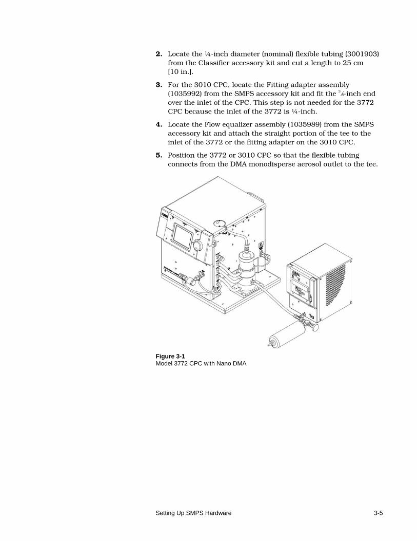
2. Locate the ¼-inch diameter (nominal) flexible tubing (3001903) from the Classifier accessory kit and cut a length to 25 cm [10 in.].
3. For the 3010 CPC, locate the Fitting adapter assembly (1035992) from the SMPS accessory kit and fit the 3⁄8-inch end over the inlet of the CPC. This step is not needed for the 3772 CPC because the inlet of the 3772 is ¼-inch.
4. Locate the Flow equalizer assembly (1035989) from the SMPS accessory kit and attach the straight portion of the tee to the inlet of the 3772 or the fitting adapter on the 3010 CPC.
5. Position the 3772 or 3010 CPC so that the flexible tubing connects from the DMA monodisperse aerosol outlet to the tee.
Figure 3-1 Model 3772 CPC with Nano DMA
3-6 Model 3936 Scanning Mobility Particle SizerTM (SMPSTM) Spectrometer
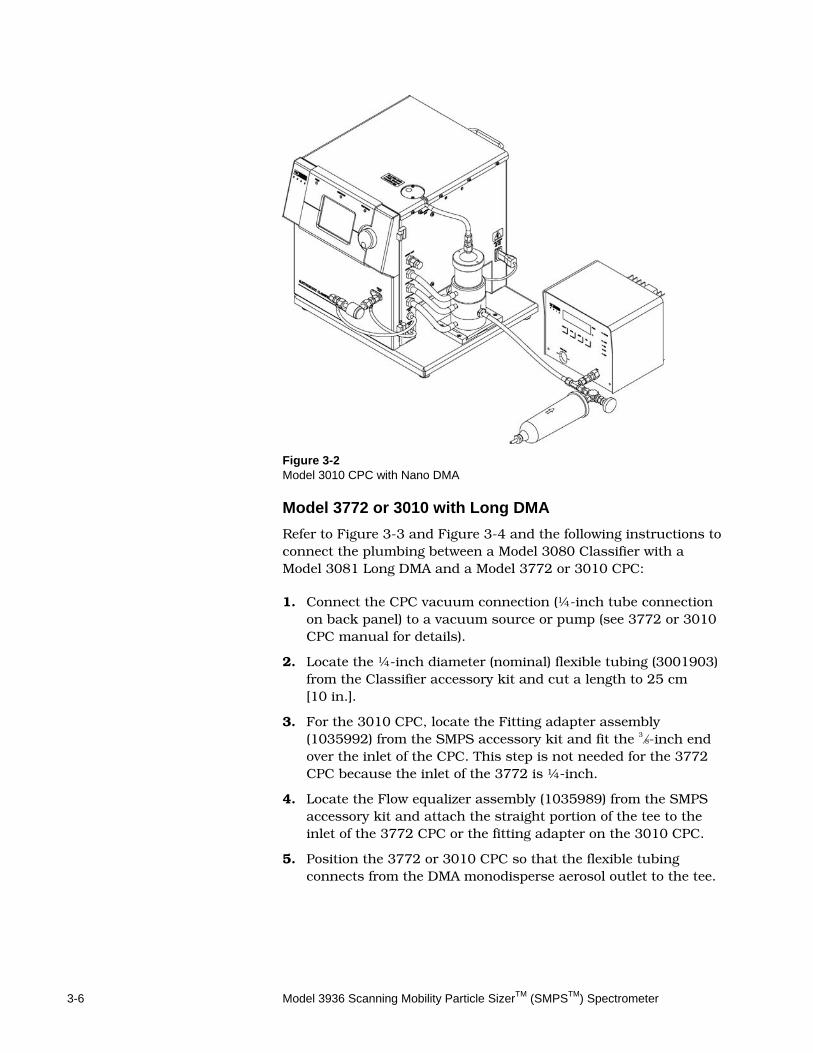
Figure 3-2 Model 3010 CPC with Nano DMA
Model 3772 or 3010 with Long DMA
Refer to Figure 3-3 and Figure 3-4 and the following instructions to connect the plumbing between a Model 3080 Classifier with a Model 3081 Long DMA and a Model 3772 or 3010 CPC:
1. Connect the CPC vacuum connection (¼-inch tube connection on back panel) to a vacuum source or pump (see 3772 or 3010 CPC manual for details).
2. Locate the ¼-inch diameter (nominal) flexible tubing (3001903) from the Classifier accessory kit and cut a length to 25 cm [10 in.].
3. For the 3010 CPC, locate the Fitting adapter assembly (1035992) from the SMPS accessory kit and fit the 3⁄8-inch end over the inlet of the CPC. This step is not needed for the 3772 CPC because the inlet of the 3772 is ¼-inch.
4. Locate the Flow equalizer assembly (1035989) from the SMPS accessory kit and attach the straight portion of the tee to the inlet of the 3772 CPC or the fitting adapter on the 3010 CPC.
5. Position the 3772 or 3010 CPC so that the flexible tubing connects from the DMA monodisperse aerosol outlet to the tee.
Setting Up SMPS Hardware 3-7
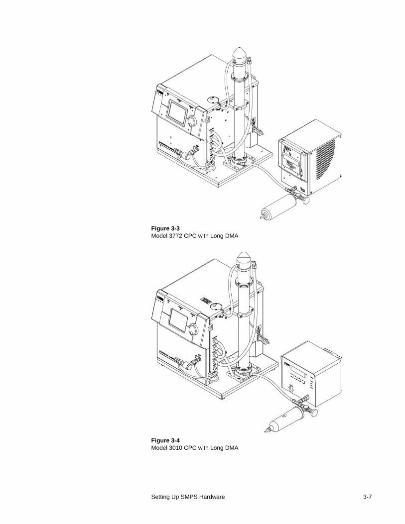
Figure 3-3 Model 3772 CPC with Long DMA
Figure 3-4 Model 3010 CPC with Long DMA
3-8 Model 3936 Scanning Mobility Particle SizerTM (SMPSTM) Spectrometer
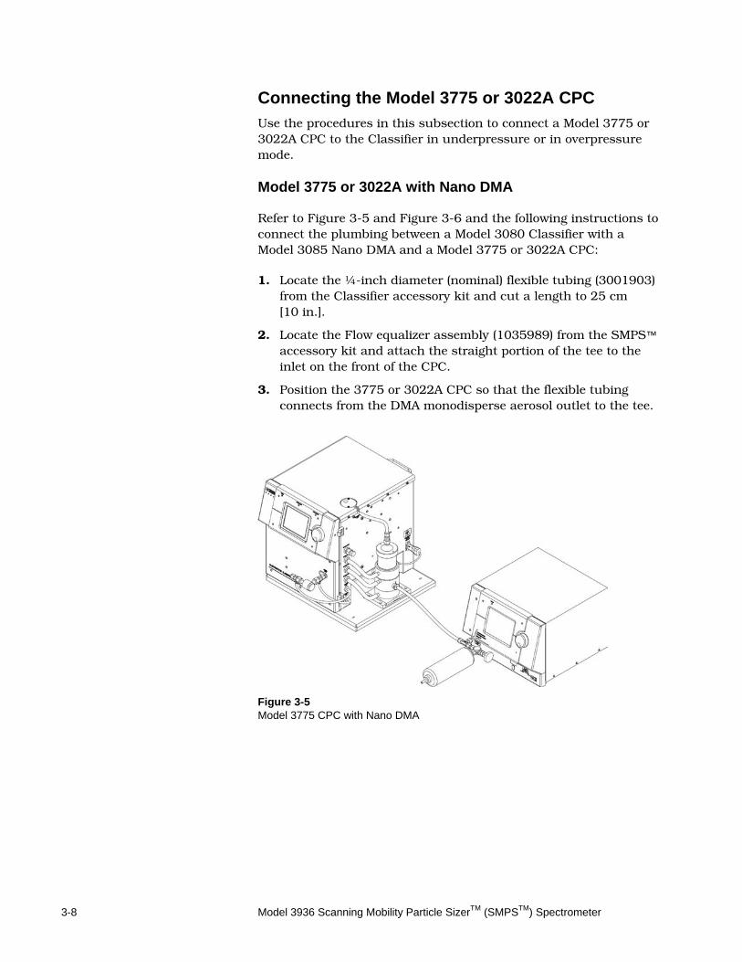
Connecting the Model 3775 or 3022A CPC Use the procedures in this subsection to connect a Model 3775 or 3022A CPC to the Classifier in underpressure or in overpressure mode. Model 3775 or 3022A with Nano DMA
Refer to Figure 3-5 and Figure 3-6 and the following instructions to connect the plumbing between a Model 3080 Classifier with a Model 3085 Nano DMA and a Model 3775 or 3022A CPC:
1. Locate the ¼-inch diameter (nominal) flexible tubing (3001903) from the Classifier accessory kit and cut a length to 25 cm [10 in.].
2. Locate the Flow equalizer assembly (1035989) from the SMPS™ accessory kit and attach the straight portion of the tee to the inlet on the front of the CPC.
3. Position the 3775 or 3022A CPC so that the flexible tubing connects from the DMA monodisperse aerosol outlet to the tee.
Figure 3-5 Model 3775 CPC with Nano DMA
Setting Up SMPS Hardware 3-9
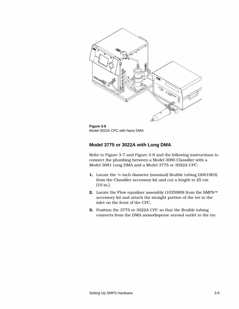
Figure 3-6 Model 3022A CPC with Nano DMA
Model 3775 or 3022A with Long DMA
Refer to Figure 3-7 and Figure 3-8 and the following instructions to connect the plumbing between a Model 3080 Classifier with a Model 3081 Long DMA and a Model 3775 or 3022A CPC:
1. Locate the ¼-inch diameter (nominal) flexible tubing (3001903) from the Classifier accessory kit and cut a length to 25 cm [10 in.].
2. Locate the Flow equalizer assembly (1035989) from the SMPS™ accessory kit and attach the straight portion of the tee to the inlet on the front of the CPC.
3. Position the 3775 or 3022A CPC so that the flexible tubing connects from the DMA monodisperse aerosol outlet to the tee.
3-10 Model 3936 Scanning Mobility Particle SizerTM (SMPSTM) Spectrometer
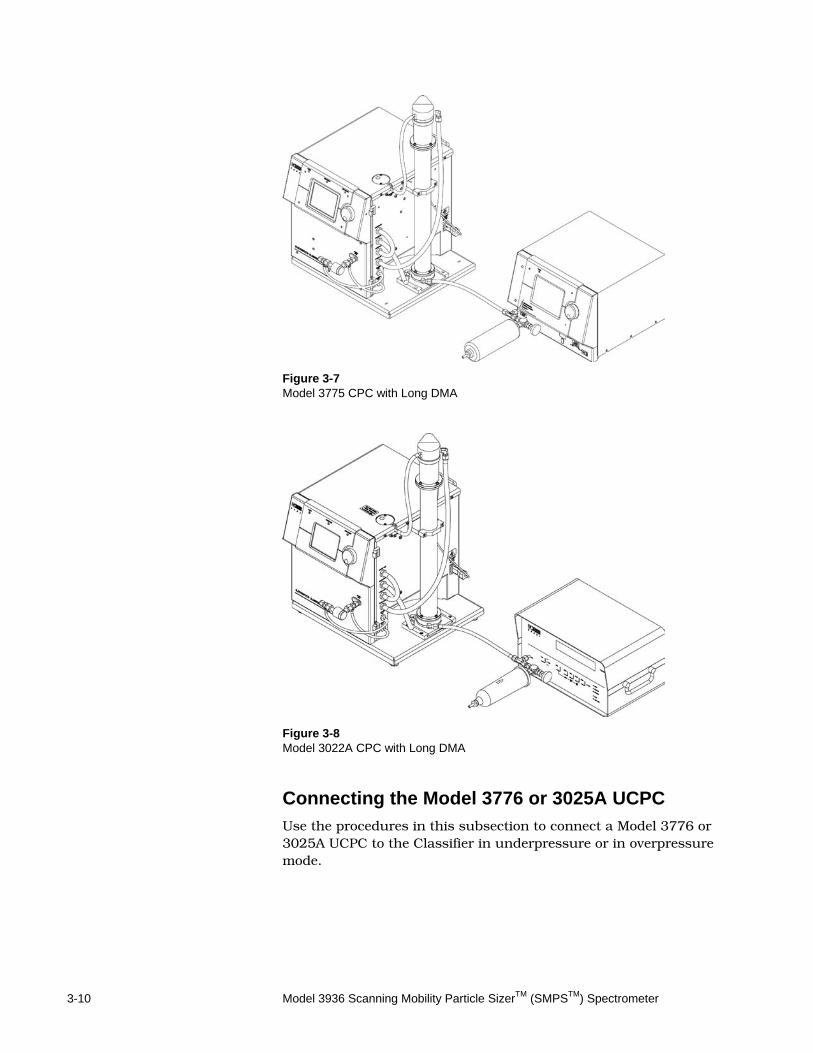
Figure 3-7 Model 3775 CPC with Long DMA
Figure 3-8 Model 3022A CPC with Long DMA
Connecting the Model 3776 or 3025A UCPC Use the procedures in this subsection to connect a Model 3776 or 3025A UCPC to the Classifier in underpressure or in overpressure mode.
Setting Up SMPS Hardware 3-11
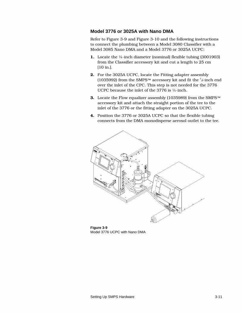
Model 3776 or 3025A with Nano DMA
Refer to Figure 3-9 and Figure 3-10 and the following instructions to connect the plumbing between a Model 3080 Classifier with a Model 3085 Nano DMA and a Model 3776 or 3025A UCPC:
1. Locate the ¼-inch diameter (nominal) flexible tubing (3001903) from the Classifier accessory kit and cut a length to 25 cm [10 in.].
2. For the 3025A UCPC, locate the Fitting adapter assembly (1035992) from the SMPS™ accessory kit and fit the 3⁄8-inch end over the inlet of the CPC. This step is not needed for the 3776 UCPC because the inlet of the 3776 is ¼-inch.
3. Locate the Flow equalizer assembly (1035989) from the SMPS™ accessory kit and attach the straight portion of the tee to the inlet of the 3776 or the fitting adapter on the 3025A UCPC.
4. Position the 3776 or 3025A UCPC so that the flexible tubing connects from the DMA monodisperse aerosol outlet to the tee.
Figure 3-9 Model 3776 UCPC with Nano DMA
3-12 Model 3936 Scanning Mobility Particle SizerTM (SMPSTM) Spectrometer
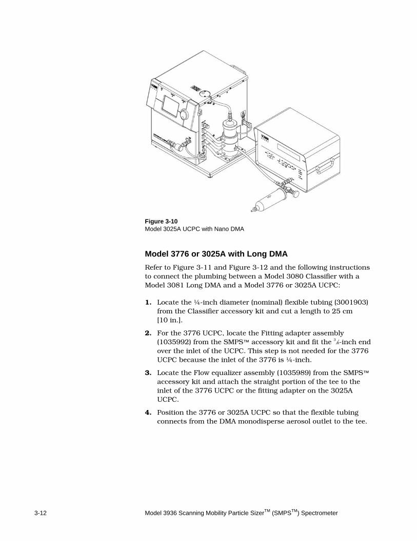
Figure 3-10 Model 3025A UCPC with Nano DMA
Model 3776 or 3025A with Long DMA
Refer to Figure 3-11 and Figure 3-12 and the following instructions to connect the plumbing between a Model 3080 Classifier with a Model 3081 Long DMA and a Model 3776 or 3025A UCPC:
1. Locate the ¼-inch diameter (nominal) flexible tubing (3001903) from the Classifier accessory kit and cut a length to 25 cm [10 in.].
2. For the 3776 UCPC, locate the Fitting adapter assembly (1035992) from the SMPS™ accessory kit and fit the 3⁄8-inch end over the inlet of the UCPC. This step is not needed for the 3776 UCPC because the inlet of the 3776 is ¼-inch.
3. Locate the Flow equalizer assembly (1035989) from the SMPS™ accessory kit and attach the straight portion of the tee to the inlet of the 3776 UCPC or the fitting adapter on the 3025A UCPC.
4. Position the 3776 or 3025A UCPC so that the flexible tubing connects from the DMA monodisperse aerosol outlet to the tee.
Setting Up SMPS Hardware 3-13
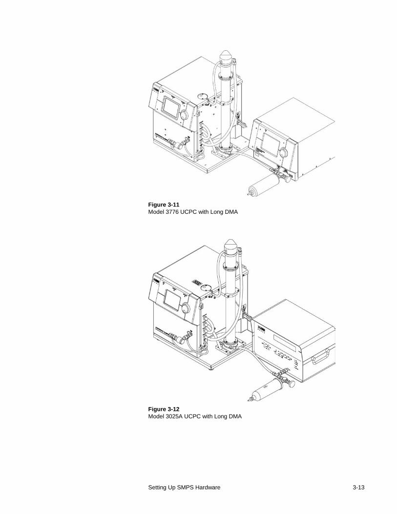
Figure 3-11 Model 3776 UCPC with Long DMA
Figure 3-12 Model 3025A UCPC with Long DMA
3-14 Model 3936 Scanning Mobility Particle SizerTM (SMPSTM) Spectrometer
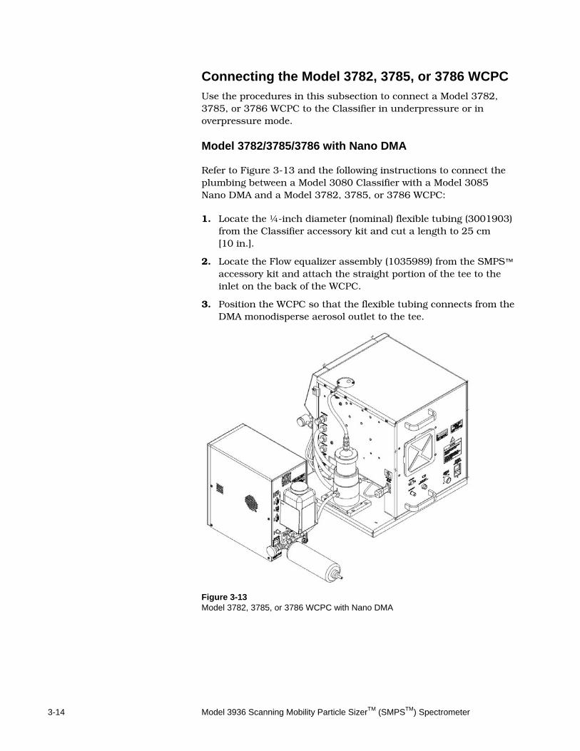
Connecting the Model 3782, 3785, or 3786 WCPC Use the procedures in this subsection to connect a Model 3782, 3785, or 3786 WCPC to the Classifier in underpressure or in overpressure mode. Model 3782/3785/3786 with Nano DMA
Refer to Figure 3-13 and the following instructions to connect the plumbing between a Model 3080 Classifier with a Model 3085 Nano DMA and a Model 3782, 3785, or 3786 WCPC:
1. Locate the ¼-inch diameter (nominal) flexible tubing (3001903) from the Classifier accessory kit and cut a length to 25 cm [10 in.].
2. Locate the Flow equalizer assembly (1035989) from the SMPS™ accessory kit and attach the straight portion of the tee to the inlet on the back of the WCPC.
3. Position the WCPC so that the flexible tubing connects from the DMA monodisperse aerosol outlet to the tee.
Figure 3-13 Model 3782, 3785, or 3786 WCPC with Nano DMA
Setting Up SMPS Hardware 3-15
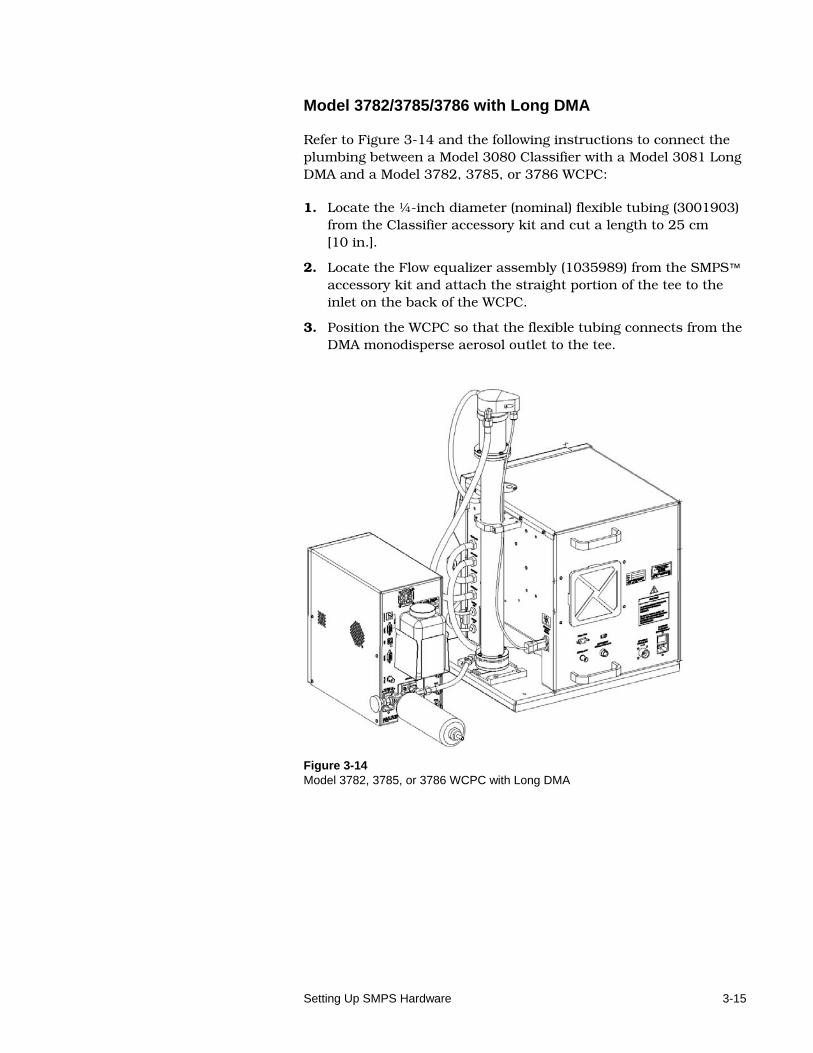
Model 3782/3785/3786 with Long DMA
Refer to Figure 3-14 and the following instructions to connect the plumbing between a Model 3080 Classifier with a Model 3081 Long DMA and a Model 3782, 3785, or 3786 WCPC:
1. Locate the ¼-inch diameter (nominal) flexible tubing (3001903) from the Classifier accessory kit and cut a length to 25 cm [10 in.].
2. Locate the Flow equalizer assembly (1035989) from the SMPS™ accessory kit and attach the straight portion of the tee to the inlet on the back of the WCPC.
3. Position the WCPC so that the flexible tubing connects from the DMA monodisperse aerosol outlet to the tee.
Figure 3-14 Model 3782, 3785, or 3786 WCPC with Long DMA

3-16 Model 3936 Scanning Mobility Particle SizerTM (SMPSTM) Spectrometer
(This page intentionally left blank)
4-1
C H A P T E R 4 Operat ing SMPS™ Hardware
After you have set up the SMPS™ spectrometer plumbing in Chapter 3, use the information in this chapter to do the following:
Select flow rates
Set flow rates
Check the SMPS™ spectrometer for laminar airflow
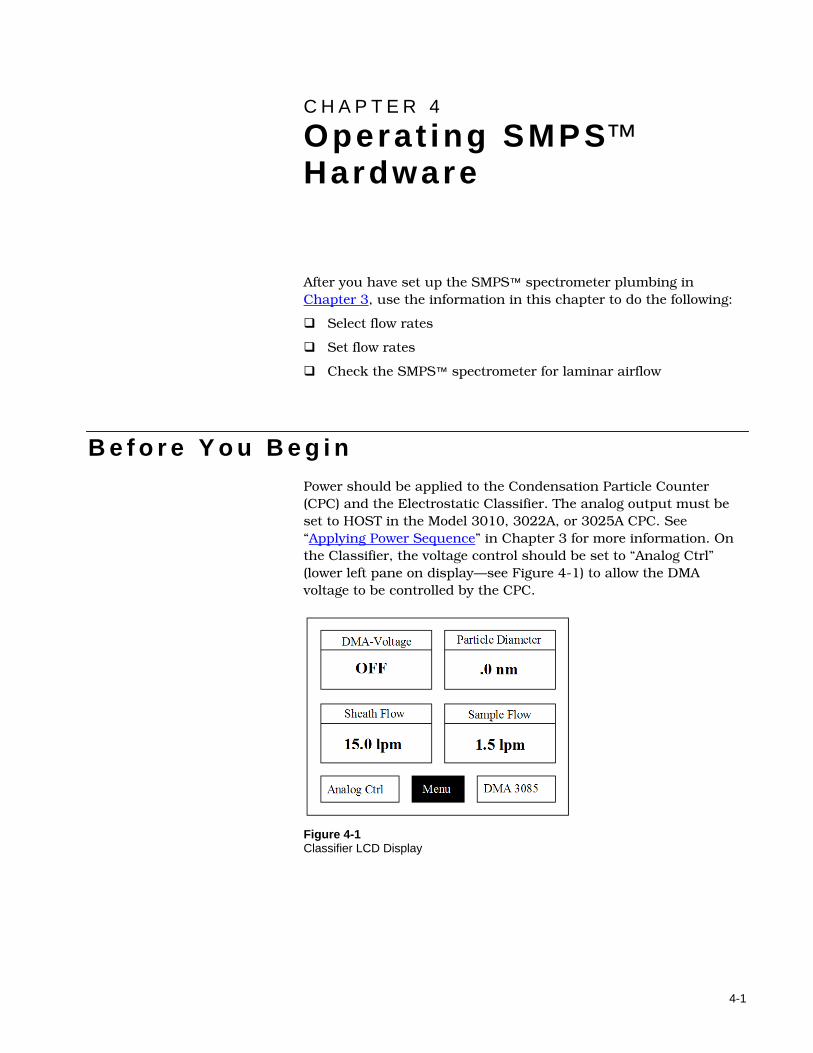
B e f o r e Y o u B e g i n Power should be applied to the Condensation Particle Counter (CPC) and the Electrostatic Classifier. The analog output must be set to HOST in the Model 3010, 3022A, or 3025A CPC. See “Applying Power Sequence” in Chapter 3 for more information. On the Classifier, the voltage control should be set to “Analog Ctrl” (lower left pane on display—see Figure 4-1) to allow the DMA voltage to be controlled by the CPC.
Figure 4-1 Classifier LCD Display
4-2 Model 3936 Scanning Mobility Particle SizerTM (SMPSTM) Spectrometer
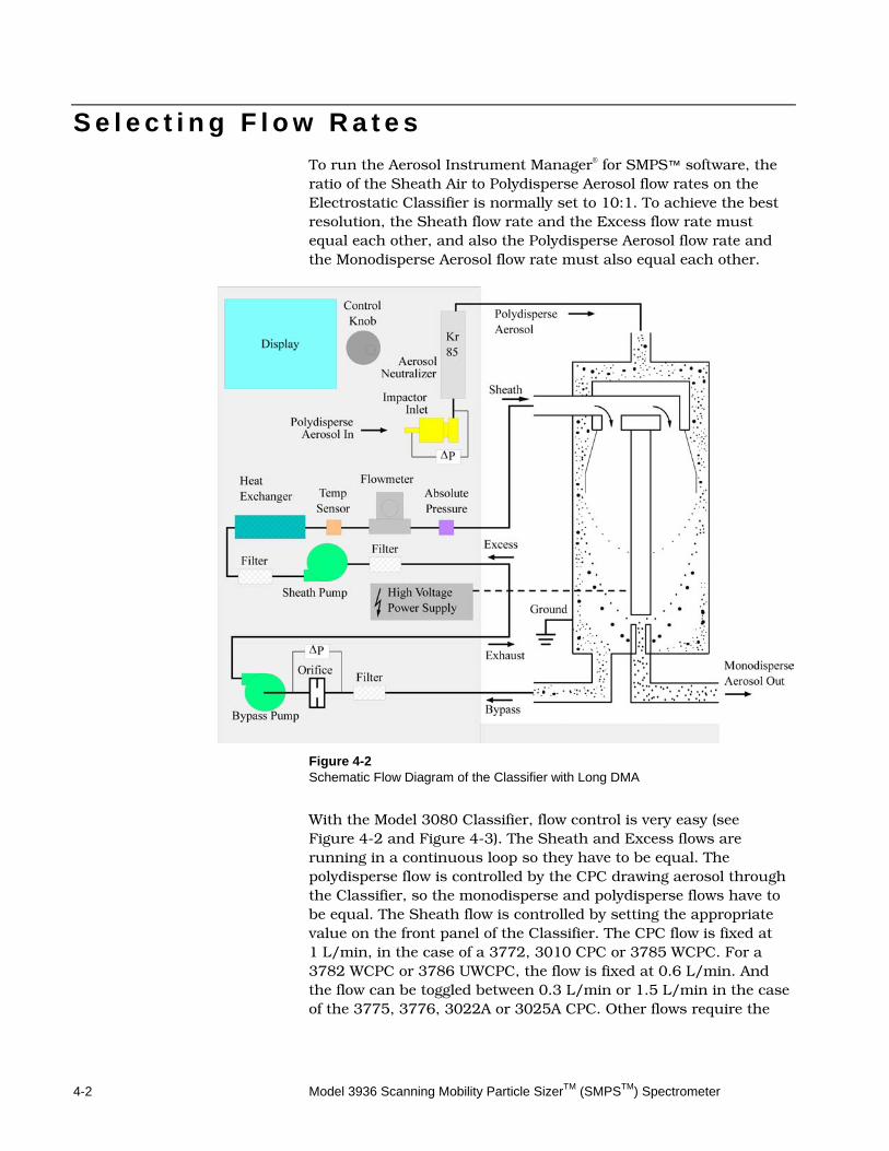
S e l e c t i n g F l o w R a t e s To run the Aerosol Instrument Manager® for SMPS™ software, the ratio of the Sheath Air to Polydisperse Aerosol flow rates on the Electrostatic Classifier is normally set to 10:1. To achieve the best resolution, the Sheath flow rate and the Excess flow rate must equal each other, and also the Polydisperse Aerosol flow rate and the Monodisperse Aerosol flow rate must also equal each other.
Figure 4-2 Schematic Flow Diagram of the Classifier with Long DMA
With the Model 3080 Classifier, flow control is very easy (see Figure 4-2 and Figure 4-3). The Sheath and Excess flows are running in a continuous loop so they have to be equal. The polydisperse flow is controlled by the CPC drawing aerosol through the Classifier, so the monodisperse and polydisperse flows have to be equal. The Sheath flow is controlled by setting the appropriate value on the front panel of the Classifier. The CPC flow is fixed at 1 L/min, in the case of a 3772, 3010 CPC or 3785 WCPC. For a 3782 WCPC or 3786 UWCPC, the flow is fixed at 0.6 L/min. And the flow can be toggled between 0.3 L/min or 1.5 L/min in the case of the 3775, 3776, 3022A or 3025A CPC. Other flows require the
Operating SMPS™ Hardware 4-3
use of the flow equalizer assembly (filter and valve) to provide filtered makeup air to the CPCs.
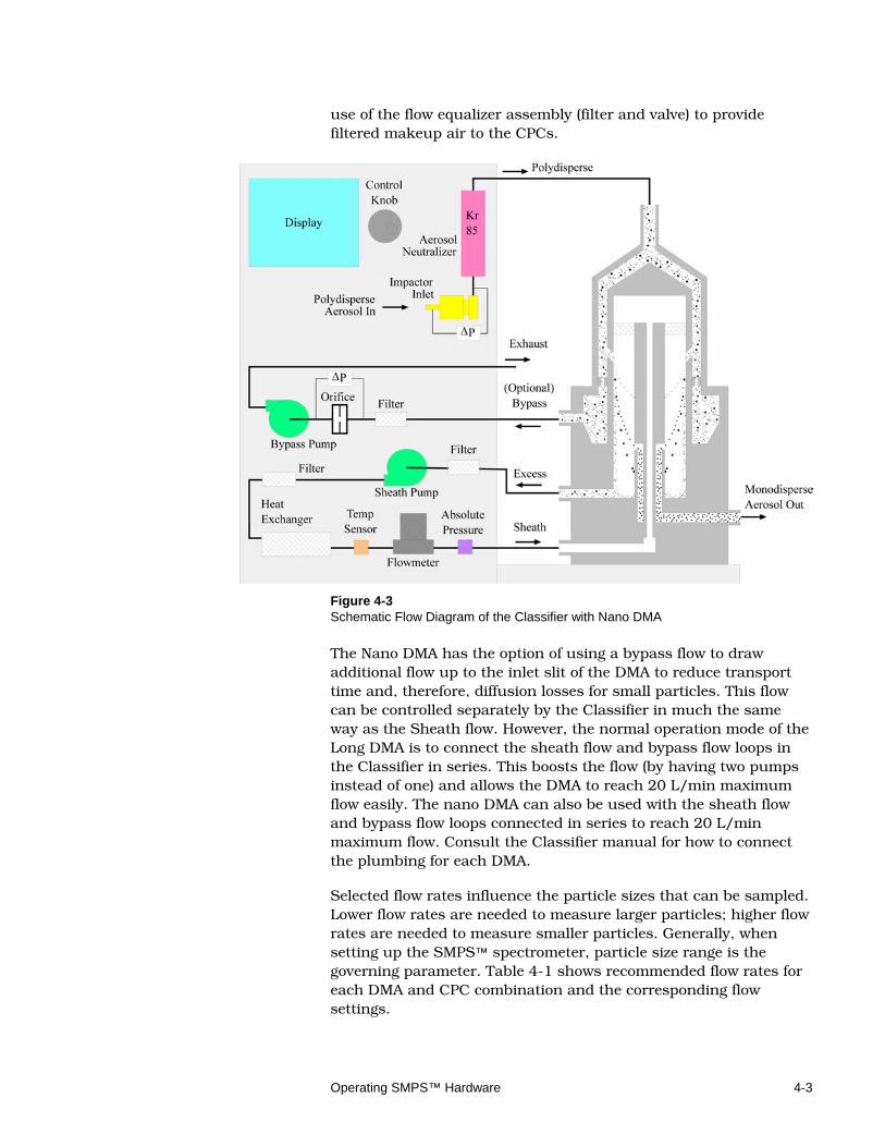
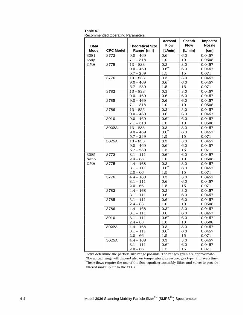
Figure 4-3 Schematic Flow Diagram of the Classifier with Nano DMA The Nano DMA has the option of using a bypass flow to draw additional flow up to the inlet slit of the DMA to reduce transport time and, therefore, diffusion losses for small particles. This flow can be controlled separately by the Classifier in much the same way as the Sheath flow. However, the normal operation mode of the Long DMA is to connect the sheath flow and bypass flow loops in the Classifier in series. This boosts the flow (by having two pumps instead of one) and allows the DMA to reach 20 L/min maximum flow easily. The nano DMA can also be used with the sheath flow and bypass flow loops connected in series to reach 20 L/min maximum flow. Consult the Classifier manual for how to connect the plumbing for each DMA. Selected flow rates influence the particle sizes that can be sampled. Lower flow rates are needed to measure larger particles; higher flow rates are needed to measure smaller particles. Generally, when setting up the SMPS™ spectrometer, particle size range is the governing parameter. Table 4-1 shows recommended flow rates for each DMA and CPC combination and the corresponding flow settings.
4-4 Model 3936 Scanning Mobility Particle SizerTM (SMPSTM) Spectrometer
Table 4-1 Recommended Operating Parameters
DMA
Model
CPC Model
Theoretical Size
Range* [nm]
Aerosol Flow
[L/min]
Sheath Flow
[L/min]
Impactor Nozzle [cm]
3081 Long DMA
3772 9.0 – 469 7.1 – 318
0.6** 1.0
6.0 10
0.0457 0.0508
3775 13 – 833 9.0 – 469 5.7 – 239
0.3 0.6**
1.5
3.0 6.0 15
0.0457 0.0457 0.071
3776 13 – 833 9.0 – 469 5.7 – 239
0.3 0.6**
1.5
3.0 6.0 15
0.0457 0.0457 0.071
3782 13 – 833 9.0 – 469
0.3** 0.6
3.0 6.0
0.0457 0.0457
3785 9.0 – 469 7.1 – 318
0.6** 1.0
6.0 10
0.0457 0.0508
3786 13 – 833 9.0 – 469
0.3** 0.6
3.0 6.0
0.0457 0.0457
3010 9.0 – 469 7.1 – 318
0.6** 1.0
6.0 10
0.0457 0.0508
3022A 13 – 833 9.0 – 469 5.7 – 239
0.3 0.6**
1.5
3.0 6.0 15
0.0457 0.0457 0.071
3025A 13 – 833 9.0 – 469 5.7 – 239
0.3 0.6**
1.5
3.0 6.0 15
0.0457 0.0457 0.071
3085 Nano DMA
3772 3.1 – 111 2.4 – 83
0.6** 1.0
6.0 10
0.0457 0.0508
3775 4.4 – 168 3.1 – 111 2.0 – 66
0.3 0.6** 1.5
3.0 6.0 15
0.0457 0.0457 0.071
3776 4.4 – 168 3.1 – 111 2.0 – 66
0.3 0.6** 1.5
3.0 6.0 15
0.0457 0.0457 0.071
3782 4.4 – 168 3.1 – 111
0.3** 0.6
3.0 6.0
0.0457 0.0457
3785 3.1 – 111 2.4 – 83
0.6** 1.0
6.0 10
0.0457 0.0508
3786 4.4 – 168 3.1 – 111
0.3** 0.6
3.0 6.0
0.0457 0.0457
3010 3.1 – 111 2.4 – 83
0.6** 1.0
6.0 10
0.0457 0.0508
3022A 4.4 – 168 3.1 – 111 2.0 – 66
0.3 0.6** 1.5
3.0 6.0 15
0.0457 0.0457 0.071
3025A 4.4 – 168 3.1 – 111 2.0 – 66
0.3 0.6** 1.5
3.0 6.0 15
0.0457 0.0457 0.071
*Flows determine the particle size range possible. The ranges given are approximate. The actual range will depend also on temperature, pressure, gas type, and scan time.
**These flows require the use of the flow equalizer assembly (filter and valve) to provide filtered makeup air to the CPCs.
Operating SMPS™ Hardware 4-5
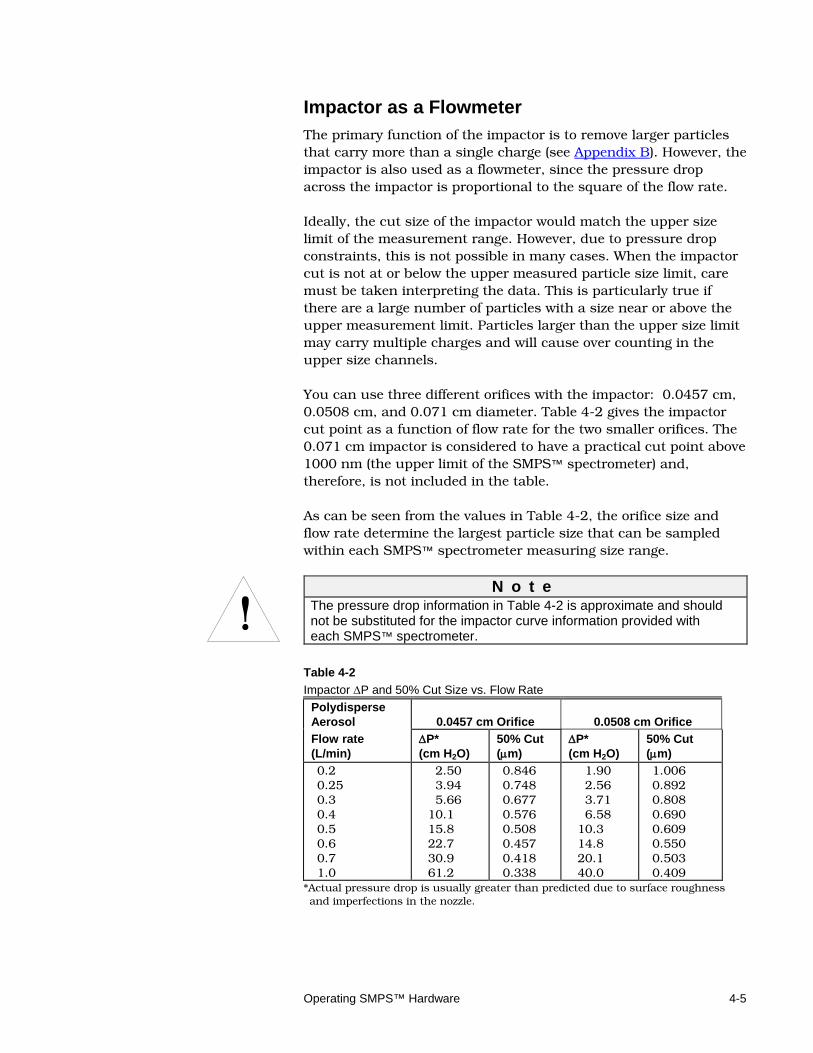
Impactor as a Flowmeter The primary function of the impactor is to remove larger particles that carry more than a single charge (see Appendix B). However, the impactor is also used as a flowmeter, since the pressure drop across the impactor is proportional to the square of the flow rate. Ideally, the cut size of the impactor would match the upper size limit of the measurement range. However, due to pressure drop constraints, this is not possible in many cases. When the impactor cut is not at or below the upper measured particle size limit, care must be taken interpreting the data. This is particularly true if there are a large number of particles with a size near or above the upper measurement limit. Particles larger than the upper size limit may carry multiple charges and will cause over counting in the upper size channels. You can use three different orifices with the impactor: 0.0457 cm, 0.0508 cm, and 0.071 cm diameter. Table 4-2 gives the impactor cut point as a function of flow rate for the two smaller orifices. The 0.071 cm impactor is considered to have a practical cut point above 1000 nm (the upper limit of the SMPS™ spectrometer) and, therefore, is not included in the table. As can be seen from the values in Table 4-2, the orifice size and flow rate determine the largest particle size that can be sampled within each SMPS™ spectrometer measuring size range.
!
N o t e The pressure drop information in Table 4-2 is approximate and should not be substituted for the impactor curve information provided with each SMPS™ spectrometer.
Table 4-2 Impactor ∆P and 50% Cut Size vs. Flow Rate
Polydisperse Aerosol
0.0457 cm Orifice
0.0508 cm Orifice
Flow rate (L/min)
∆P* (cm H2O)
50% Cut (µm)
∆P* (cm H2O)
50% Cut (µm)
0.2 0.25 0.3 0.4 0.5 0.6 0.7 1.0
2.50 3.94 5.66 10.1 15.8 22.7 30.9 61.2
0.846 0.748 0.677 0.576 0.508 0.457 0.418 0.338
1.90 2.56 3.71 6.58 10.3 14.8 20.1 40.0
1.006 0.892 0.808 0.690 0.609 0.550 0.503 0.409
*Actual pressure drop is usually greater than predicted due to surface roughness and imperfections in the nozzle.
4-6 Model 3936 Scanning Mobility Particle SizerTM (SMPSTM) Spectrometer
S e t t i n g F l o w R a t e s Use the information in this section to set the flows for each of the CPC types in under and overpressure modes.
For each of the CPCs there is a preferred operating flow rate for the polydisperse and monodisperse flows (they are equal—see Table 4-1). When operated at these flows, the Classifier should be in underpressure mode. In underpressure mode, the flow is pulled through the Classifier; in overpressure mode, the flow is pushed through the Classifier.
Underpressure Mode When the CPCs are run at the flows recommended in Table 4-1 (flow rates that are not marked with **), the valve on the flow equalizer assembly should be fully closed. This allows all the flow of the CPC to be drawn through the Classifier. To run the SMPS™ spectrometer with a lower flow rate than normally used with a particular CPC (for example 0.6 L/min with a Model 3772 CPC), adjust the valve on the flow equalizer assembly until the polydisperse flow (measured with the impactor flow rate) reaches the set value.
Overpressure Mode To operate the SMPS™ spectrometer with a flow rate higher than normally used with a particular CPC (for example, 1.5 L/min with a Model 3772 CPC), the SMPS™ spectrometer is in overpressure mode. This means pushing 1.5 L/min from the aerosol source through the aerosol inlet and then allowing the filter in the flow equalizer assembly to vent the excess flow. In this case, the valve should be fully open. Once again, the actual polydisperse flow can be monitored with the impactor flowmeter.
S M P S S p e c t r o m e t e r C h e c k Before operating the SMPS™ spectrometer, check the system to ensure the system is leak-tight and the flows are laminar. All flow rates must be set to proper values before checking the system (see “Setting Flow Rates” in this chapter).
Operating SMPS™ Hardware 4-7
1. On the Classifier, the voltage control should be set to “Panel Ctrl” (lower left pane on display—see Figure 4-1) to allow the DMA voltage to be controlled from the front panel, and the DMA Voltage control (upper left pane on display) must be set to 0 volts (off).
2. Check the CPC concentration display after a few minutes.
If the display reads less than 0.1 particle/cm3, the SMPS spectrometer is leak-tight and flows are laminar. The system is now ready for sampling.
If the concentration readings do not reduce to less than 0.1 particle/cm3, the SMPS™ spectrometer is not set up correctly and taking measurements at this point would not produce useful data. In this case, check to see that all plumbing fittings are tight. If this fails, see the “Testing for Leaks” section in Chapter 5.
3. Install the HEPA filter (inlet filter 1036015 from accessory kit) on the inlet and allow the system to clean out for a few minutes. Then, scan the voltage slowly (over 2 minutes scan time) from 0 to 10,000 volts. Monitor the CPC reading as you go.
If the display reads less than 0.1 particle/cm3, the SMPS™ spectrometer is leak-tight. The system is now ready for sampling.
If the concentration readings do not reduce to less than 0.1 particle/cm3, there may be a leak in the system upstream of the DMA. Check that the neutralizer and impactor (if used) are installed correctly and fittings are tight. If this fails, see the “Testing for Leaks” section in Chapter 5.

4-8 Model 3936 Scanning Mobility Particle SizerTM (SMPSTM) Spectrometer
(This page intentionally left blank)
5-1
C H A P T E R 5 Mainta in ing and Troubleshoot ing the SMPS™ Spectrometer
This chapter gives maintenance recommendations, as well as a section on troubleshooting the Model 3936 Scanning Mobility Particle Sizer™ (SMPS™) Spectrometer.
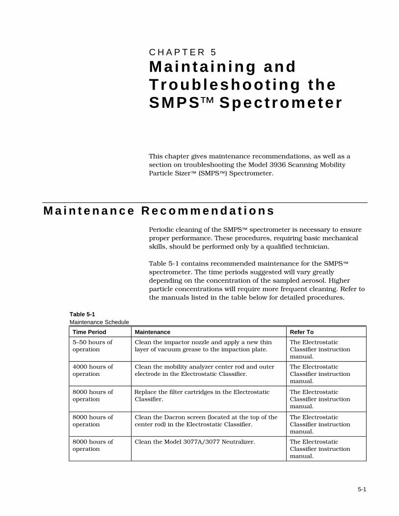
M a i n t e n a n c e R e c o m m e n d a t i o n s Periodic cleaning of the SMPS™ spectrometer is necessary to ensure proper performance. These procedures, requiring basic mechanical skills, should be performed only by a qualified technician. Table 5-1 contains recommended maintenance for the SMPS™ spectrometer. The time periods suggested will vary greatly depending on the concentration of the sampled aerosol. Higher particle concentrations will require more frequent cleaning. Refer to the manuals listed in the table below for detailed procedures.
Table 5-1 Maintenance Schedule
Time Period Maintenance Refer To
5–50 hours of operation
Clean the impactor nozzle and apply a new thin layer of vacuum grease to the impaction plate.
The Electrostatic Classifier instruction manual.
4000 hours of operation
Clean the mobility analyzer center rod and outer electrode in the Electrostatic Classifier.
The Electrostatic Classifier instruction manual.
8000 hours of operation
Replace the filter cartridges in the Electrostatic Classifier.
The Electrostatic Classifier instruction manual.
8000 hours of operation
Clean the Dacron screen (located at the top of the center rod) in the Electrostatic Classifier.
The Electrostatic Classifier instruction manual.
8000 hours of operation
Clean the Model 3077A/3077 Neutralizer. The Electrostatic Classifier instruction manual.
5-2 Model 3936 Scanning Mobility Particle SizerTM (SMPSTM) Spectrometer
Time Period Maintenance Refer To
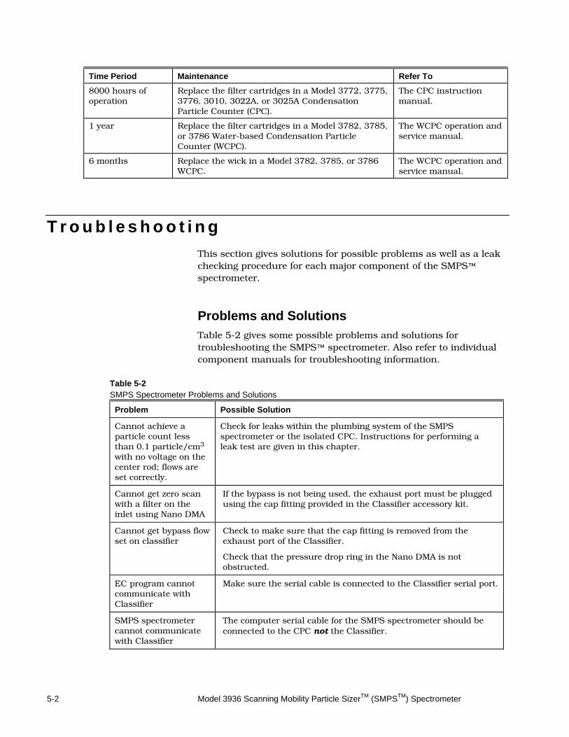
8000 hours of operation
Replace the filter cartridges in a Model 3772, 3775, 3776, 3010, 3022A, or 3025A Condensation Particle Counter (CPC).
The CPC instruction manual.
1 year Replace the filter cartridges in a Model 3782, 3785, or 3786 Water-based Condensation Particle Counter (WCPC).
The WCPC operation and service manual.
6 months Replace the wick in a Model 3782, 3785, or 3786 WCPC.
The WCPC operation and service manual.
T r o u b l e s h o o t i n g This section gives solutions for possible problems as well as a leak checking procedure for each major component of the SMPS™ spectrometer.
Problems and Solutions Table 5-2 gives some possible problems and solutions for troubleshooting the SMPS™ spectrometer. Also refer to individual component manuals for troubleshooting information.
Table 5-2 SMPS Spectrometer Problems and Solutions
Problem Possible Solution
Cannot achieve a particle count less than 0.1 particle/cm3 with no voltage on the center rod; flows are set correctly.
Check for leaks within the plumbing system of the SMPS spectrometer or the isolated CPC. Instructions for performing a leak test are given in this chapter.
Cannot get zero scan with a filter on the inlet using Nano DMA
If the bypass is not being used, the exhaust port must be plugged using the cap fitting provided in the Classifier accessory kit.
Cannot get bypass flow set on classifier
Check to make sure that the cap fitting is removed from the exhaust port of the Classifier.
Check that the pressure drop ring in the Nano DMA is not obstructed.
EC program cannot communicate with Classifier
Make sure the serial cable is connected to the Classifier serial port.
SMPS spectrometer cannot communicate with Classifier
The computer serial cable for the SMPS spectrometer should be connected to the CPC not the Classifier.
Maintaining and Troubleshooting the SMPS Spectrometer 5-3
Testing for Leaks Use the information in this section to check the SMPS™ spectrometer plumbing for leaks. Use the Classifier Manual procedures to check for leaks in the Model 3080 Classifier, and use the CPC manual procedures to check for leaks in your CPC. System Plumbing
Use the following procedure to check the SMPS™ spectrometer plumbing.
1. Disconnect the CPC from the Classifier and disconnect the flow equalizer assembly from the CPC.
2. Open the valve in the flow equalizer assembly and plug any two of the three ports.
3. Connect a compressed air source (3 psi) to the unplugged port fitting.
4. Apply soapy water to the external plumbing joints.
5. Look for small bubbles around the joints. If a leak is located, tighten the joint or replace the ferrules and repeat the leak test.
6. If no leaks are found, check for leaks within the Classifier or CPC.

5-4 Model 3936 Scanning Mobility Particle SizerTM (SMPSTM) Spectrometer
(This page intentionally left blank)
6-1
C H A P T E R 6 Serv ice
This chapter gives directions for contacting people at TSI Incorporated for technical information and directions for returning the Model 3936 Scanning Mobility Particle Sizer™ (SMPS™) Spectrometer for service.
T e c h n i c a l C o n t a c t s If you have any difficulty setting up or operating the SMPS™
spectrometer, or if you have technical or application questions about this system, contact an applications engineer at TSI Incorporated, 1-800-874-2811 (USA) or 001 (651) 490-2811.
If the SMPS™ spectrometer does not operate properly, or if you are returning it for service, visit our website at http://rma.tsi.com or contact TSI at:
TSI Incorporated 500 Cardigan Road Shoreview, MN 55126 USA Phone: 1-800-874-2811 (USA) or 001 (651) 490-2811 E-mail: [email protected] Website: http://service.tsi.com
6-2 Model 3936 Scanning Mobility Particle SizerTM (SMPSTM) Spectrometer
R e t u r n i n g t h e S M P S™ S p e c t r o m e t e r f o r S e r v i c e
Before returning the SMPS™ spectrometer to TSI for service, visit our website at http://rma.tsi.com or call TSI at 1-800-874-2811 (USA) or (651) 490-2811 for specific return instructions. Customer Service will need this information when you call:
The instrument model number
The instrument serial number
A purchase order number (unless under warranty)
A billing address
A shipping address
Condensation Particle Counters (CPC) must be drained of all liquid and dried out, and the Neutralizer must be removed from the Electrostatic Classifier before returning the SMPS™ spectrometer. See the Neutralizer, Classifier, and CPC manuals for more information.
Use the original packing material to return the instrument to TSI. If you no longer have the original packing material, seal off any ports to prevent debris from entering the instrument and ensure that the indicator lights and the connectors on the instrument front and back panels are protected.
A-1
A P P E N D I X A Speci f icat ions
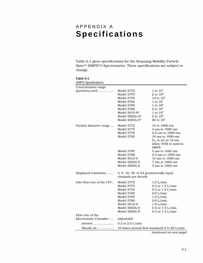
Table A-1 gives specifications for the Scanning Mobility Particle Sizer™ (SMPS™) Spectrometer. These specifications are subject to change. Table A-1 SMPS Specifications
Concentration range (particles/cm3) ................. Model 3772 1 to 107
Model 3775 2 to 108 Model 3776 10 to 107
Model 3782 1 to 107 Model 3785 1 to 108
Model 3786 2 to 107
Model 3010-S* 1 to 107
Model 3022A-S* 2 to 108
Model 3025A-S* 20 to 107
Particle diameter range .... Model 3772 10 to 1000 nm
Model 3775 4 nm to 1000 nm Model 3776 2.5 nm to 1000 nm Model 3782 10 nm to 1000 nm
D50 is set at 10 nm when 3782 is used in SMPS
Model 3785 5 nm to 1000 nm Model 3786 2.5 nm to 1000 nm Model 3010-S 10 nm to 1000 nm Model 3022A-S 7 nm to 1000 nm Model 3025A-S 3 nm to 1000 nm
Displayed resolution ........ 4, 8, 16, 32, or 64 geometrically equal
channels per decade Inlet flow rate of the CPC . Model 3772 1.0 L/min
Model 3775 0.3 or 1.5 L/min Model 3776 0.3 or 1.5 L/min Model 3782 0.6 L/min Model 3785 1.0 L/min Model 3786 0.6 L/min Model 3010-S 1.0 L/min Model 3022A-S 0.3 or 1.5 L/min Model 3025A-S 0.3 or 1.5 L/min
Flow rate of the Electrostatic Classifier ..... Adjustable
Aerosol ...................... 0.2 to 2.0 L/min
Sheath air ................. 10 times aerosol flow (nominal) 2 to 20 L/min (continued on next page)
A-2 Model 3936 Scanning Mobility Particle SizerTM (SMPSTM) Spectrometer
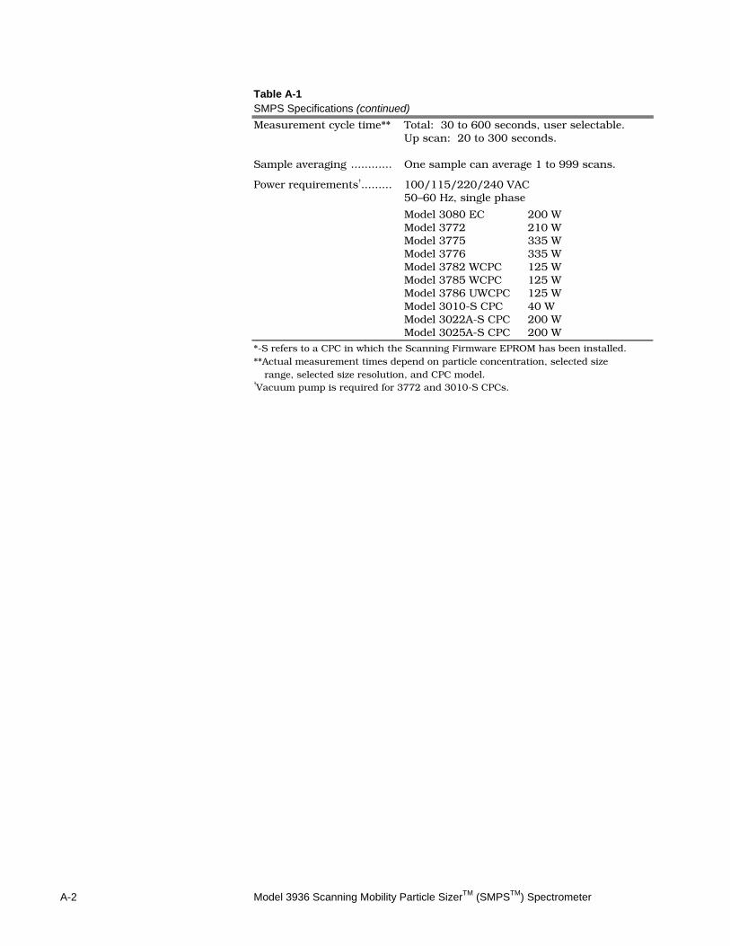
Table A-1 SMPS Specifications (continued)
Measurement cycle time** Total: 30 to 600 seconds, user selectable. Up scan: 20 to 300 seconds.
Sample averaging ............ One sample can average 1 to 999 scans. Power requirements† ......... 100/115/220/240 VAC 50–60 Hz, single phase
Model 3080 EC 200 W Model 3772 210 W Model 3775 335 W Model 3776 335 W Model 3782 WCPC 125 W Model 3785 WCPC 125 W Model 3786 UWCPC 125 W
Model 3010-S CPC 40 W Model 3022A-S CPC 200 W
Model 3025A-S CPC 200 W *-S refers to a CPC in which the Scanning Firmware EPROM has been installed. **Actual measurement times depend on particle concentration, selected size
range, selected size resolution, and CPC model. †Vacuum pump is required for 3772 and 3010-S CPCs.
B-1
A P P E N D I X B Theory of Operat ion
This appendix describes the theory of operation and working equations for the individual instruments that make up the Scanning Mobility Particle Sizer™ (SMPS™) Spectrometer.
I n t r o d u c t i o n The SMPS™ spectrometer measures the size distribution of submicrometer aerosols using an electrical mobility detection technique. The particles are classified with a Model 3080 Electrostatic Classifier with a Model 3081 Long DMA, or a Model 3085 Nano DMA. The particle concentration is measured with a Model 3772, 3775, 3776, 3010, 3022A, 3025A Condensation Particle Counter (CPC), 3782, 3785, or 3786 Water-based Condensation Particle Counter (WCPC). The SMPS™ spectrometer is automated with a personal computer that controls the individual instruments and performs data reduction using the Aerosol Instrument Manager® Software for SMPS™ spectrometer.
H i s t o r y Electrical mobility techniques have been used to measure the size distribution of aerosols since the work of Rohmann [1923]. The differential mobility analyzer (DMA) was developed and used initially for electrical mobility measurements of submicrometer particles [Hewitt, 1957]. Liu and Pui [1974] used the differential mobility analyzer with a bipolar charger to produce monodisperse aerosols of known size. Their design was used to develop the first commercial DMA, the TSI Model 3071 Electrostatic Classifier. Not long after the development of the DMA, Knutson and Whitby [1975] incorporated the DMA into a particle-sizing system. The commercial system is known as the Model 3932 Differential Mobility Particle Sizer (DMPS).
B-2 Model 3936 Scanning Mobility Particle SizerTM (SMPSTM) Spectrometer
The interface hardware was developed by TSI Incorporated. Knutson [1976] developed a data inversion technique for obtaining the initial aerosol size distribution based on the measured particle mobility distribution. A data inversion technique similar to Knutson’s was used in the commercial DMPS/C data reduction. The data inversion technique is based on the work of Plomp et al. [1982] and Hoppel [1978], and the data reduction technique was developed by Fissan et al. [1982]. The approximation of the bipolar charge distribution on submicrometer particles has been taken from the work of Wiedensohler [1986, 1987] and Wiedensohler and Fissan [1988]. In 1989, Wang and Flagan improved upon the system by using a dynamically scanned DMA voltage. This system, called SEMS (Scanning Electrical Mobility Spectrometer), provided for rapid aerosol distribution measurements. Instead of requiring several intervals of ten minutes each to measure a size distribution, the SEMS could provide results in less than one minute. In 1993, TSI commercialized the scanning system as the SMPS™ spectrometer, In January of 1999 TSI began shipping a complete redesign of earlier Classifier models as the Model 3080 with modular DMAs. The instrument includes improvements such as:
Interchangeable differential mobility analyzers.
Recirculating flow for precise match of sheath and excess flows.
Microprocessor-controlled volumetric flow with laminar flow element.
Convenient front-panel design with control knob and built-in display.
Electronic control of flow, voltage, particle-size, and instrument functions.
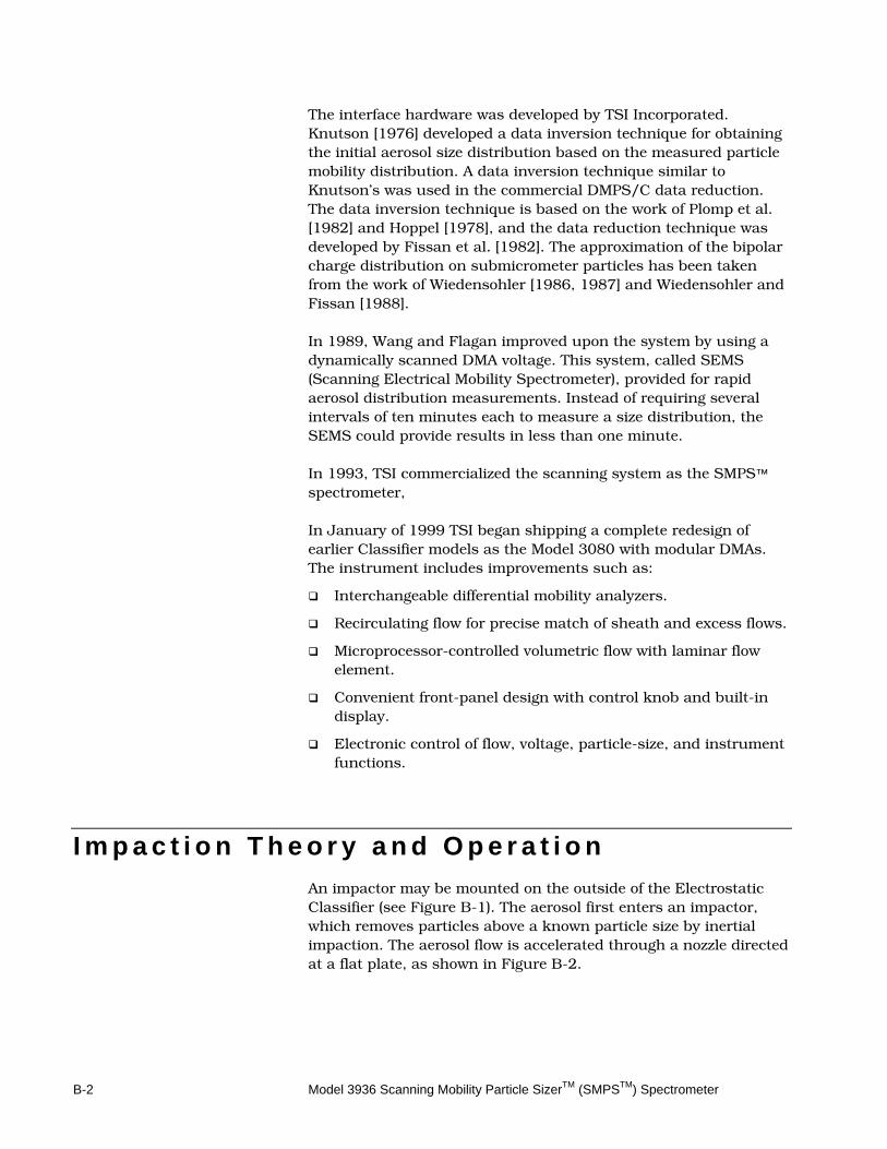
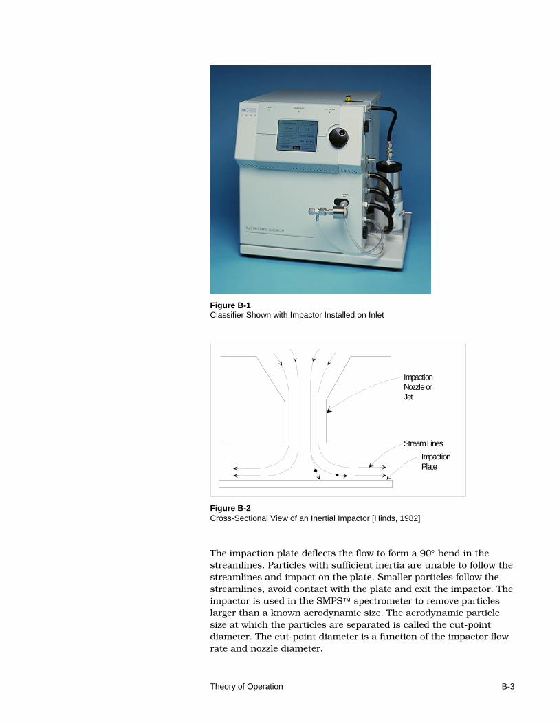
I m p a c t i o n T h e o r y a n d O p e r a t i o n An impactor may be mounted on the outside of the Electrostatic Classifier (see Figure B-1). The aerosol first enters an impactor, which removes particles above a known particle size by inertial impaction. The aerosol flow is accelerated through a nozzle directed at a flat plate, as shown in Figure B-2.
Theory of Operation B-3
Figure B-1 Classifier Shown with Impactor Installed on Inlet
ImpactionNozzle orJet
Stream Lines
ImpactionPlate
Figure B-2 Cross-Sectional View of an Inertial Impactor [Hinds, 1982] The impaction plate deflects the flow to form a 90° bend in the streamlines. Particles with sufficient inertia are unable to follow the streamlines and impact on the plate. Smaller particles follow the streamlines, avoid contact with the plate and exit the impactor. The impactor is used in the SMPS™ spectrometer to remove particles larger than a known aerodynamic size. The aerodynamic particle size at which the particles are separated is called the cut-point diameter. The cut-point diameter is a function of the impactor flow rate and nozzle diameter.
B-4 Model 3936 Scanning Mobility Particle SizerTM (SMPSTM) Spectrometer
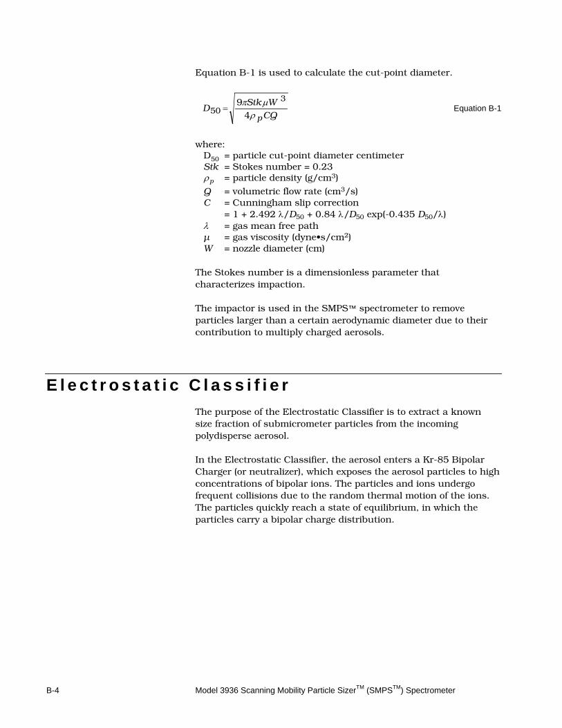
Equation B-1 is used to calculate the cut-point diameter.
CQ
WStkD
pρµπ
49 3
50 =
Equation B-1
where:
D50 = particle cut-point diameter centimeter Stk = Stokes number = 0.23 ρp = particle density (g/cm3)
Q = volumetric flow rate (cm3/s) C = Cunningham slip correction = 1 + 2.492 λ/D50 + 0.84 λ/D50 exp(-0.435 D50/λ) λ = gas mean free path µ = gas viscosity (dyne•s/cm2) W = nozzle diameter (cm)
The Stokes number is a dimensionless parameter that characterizes impaction. The impactor is used in the SMPS™ spectrometer to remove particles larger than a certain aerodynamic diameter due to their contribution to multiply charged aerosols.
E l e c t r o s t a t i c C l a s s i f i e r The purpose of the Electrostatic Classifier is to extract a known size fraction of submicrometer particles from the incoming polydisperse aerosol. In the Electrostatic Classifier, the aerosol enters a Kr-85 Bipolar Charger (or neutralizer), which exposes the aerosol particles to high concentrations of bipolar ions. The particles and ions undergo frequent collisions due to the random thermal motion of the ions. The particles quickly reach a state of equilibrium, in which the particles carry a bipolar charge distribution.
Theory of Operation B-5
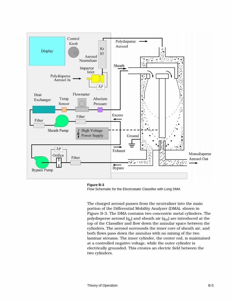
Figure B-3 Flow Schematic for the Electrostatic Classifier with Long DMA The charged aerosol passes from the neutralizer into the main portion of the Differential Mobility Analyzer (DMA), shown in Figure B-3. The DMA contains two concentric metal cylinders. The polydisperse aerosol (qa) and sheath air (qsh) are introduced at the top of the Classifier and flow down the annular space between the cylinders. The aerosol surrounds the inner core of sheath air, and both flows pass down the annulus with no mixing of the two laminar streams. The inner cylinder, the center rod, is maintained at a controlled negative voltage, while the outer cylinder is electrically grounded. This creates an electric field between the two cylinders.
B-6 Model 3936 Scanning Mobility Particle SizerTM (SMPSTM) Spectrometer
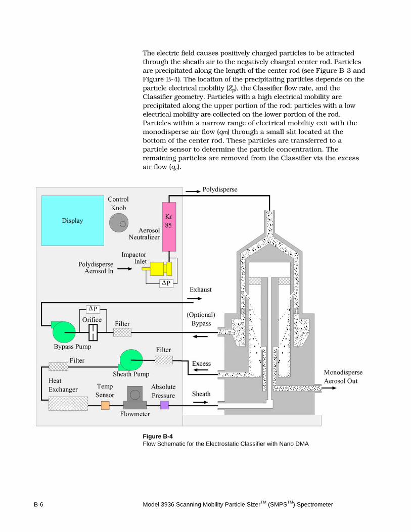
The electric field causes positively charged particles to be attracted through the sheath air to the negatively charged center rod. Particles are precipitated along the length of the center rod (see Figure B-3 and Figure B-4). The location of the precipitating particles depends on the particle electrical mobility (Zp), the Classifier flow rate, and the Classifier geometry. Particles with a high electrical mobility are precipitated along the upper portion of the rod; particles with a low electrical mobility are collected on the lower portion of the rod. Particles within a narrow range of electrical mobility exit with the monodisperse air flow (qm) through a small slit located at the bottom of the center rod. These particles are transferred to a particle sensor to determine the particle concentration. The remaining particles are removed from the Classifier via the excess air flow (qe).
Figure B-4 Flow Schematic for the Electrostatic Classifier with Nano DMA
Theory of Operation B-7
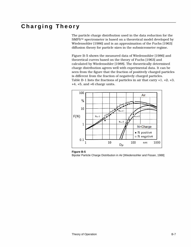
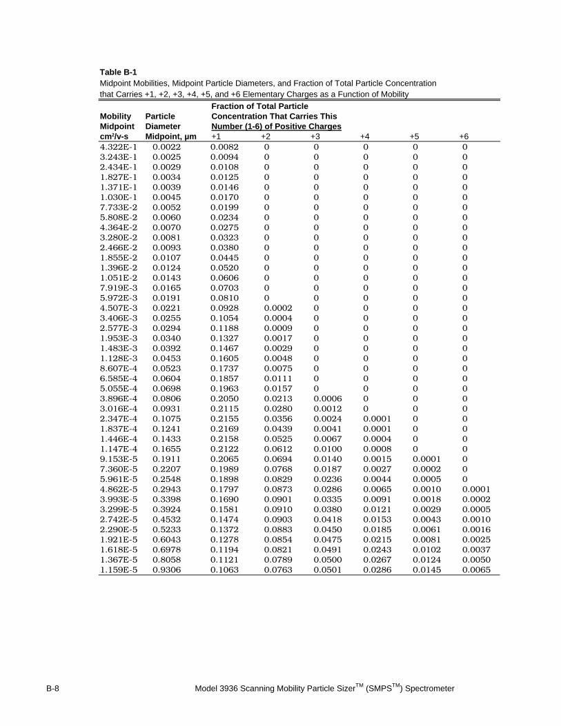
C h a r g i n g T h e o r y The particle charge distribution used in the data reduction for the SMPS™ spectrometer is based on a theoretical model developed by Wiedensohler [1986] and is an approximation of the Fuchs [1963] diffusion theory for particle sizes in the submicrometer regime. Figure B-5 shows the measured data of Wiedensohler [1986] and theoretical curves based on the theory of Fuchs [1963] and calculated by Wiedensohler [1988]. The theoretically determined charge distribution agrees well with experimental data. It can be seen from the figure that the fraction of positively charged particles is different from the fraction of negatively charged particles. Table B-1 lists the fractions of particles in air that carry +1, +2, +3, +4, +5, and +6 charge units.
Figure B-5 Bipolar Particle Charge Distribution in Air [Wiedensohler and Fissan, 1988]
B-8 Model 3936 Scanning Mobility Particle SizerTM (SMPSTM) Spectrometer
Table B-1 Midpoint Mobilities, Midpoint Particle Diameters, and Fraction of Total Particle Concentration that Carries +1, +2, +3, +4, +5, and +6 Elementary Charges as a Function of Mobility
Fraction of Total Particle Mobility Particle Concentration That Carries This Midpoint Diameter Number (1-6) of Positive Charges
cm2/v-s Midpoint, µm +1 +2 +3 +4 +5 +6 4.322E-1 0.0022 0.0082 0 0 0 0 0 3.243E-1 0.0025 0.0094 0 0 0 0 0 2.434E-1 0.0029 0.0108 0 0 0 0 0 1.827E-1 0.0034 0.0125 0 0 0 0 0 1.371E-1 0.0039 0.0146 0 0 0 0 0 1.030E-1 0.0045 0.0170 0 0 0 0 0 7.733E-2 0.0052 0.0199 0 0 0 0 0 5.808E-2 0.0060 0.0234 0 0 0 0 0 4.364E-2 0.0070 0.0275 0 0 0 0 0 3.280E-2 0.0081 0.0323 0 0 0 0 0 2.466E-2 0.0093 0.0380 0 0 0 0 0 1.855E-2 0.0107 0.0445 0 0 0 0 0 1.396E-2 0.0124 0.0520 0 0 0 0 0 1.051E-2 0.0143 0.0606 0 0 0 0 0 7.919E-3 0.0165 0.0703 0 0 0 0 0 5.972E-3 0.0191 0.0810 0 0 0 0 0 4.507E-3 0.0221 0.0928 0.0002 0 0 0 0 3.406E-3 0.0255 0.1054 0.0004 0 0 0 0 2.577E-3 0.0294 0.1188 0.0009 0 0 0 0 1.953E-3 0.0340 0.1327 0.0017 0 0 0 0 1.483E-3 0.0392 0.1467 0.0029 0 0 0 0 1.128E-3 0.0453 0.1605 0.0048 0 0 0 0 8.607E-4 0.0523 0.1737 0.0075 0 0 0 0 6.585E-4 0.0604 0.1857 0.0111 0 0 0 0 5.055E-4 0.0698 0.1963 0.0157 0 0 0 0 3.896E-4 0.0806 0.2050 0.0213 0.0006 0 0 0 3.016E-4 0.0931 0.2115 0.0280 0.0012 0 0 0 2.347E-4 0.1075 0.2155 0.0356 0.0024 0.0001 0 0 1.837E-4 0.1241 0.2169 0.0439 0.0041 0.0001 0 0 1.446E-4 0.1433 0.2158 0.0525 0.0067 0.0004 0 0 1.147E-4 0.1655 0.2122 0.0612 0.0100 0.0008 0 0 9.153E-5 0.1911 0.2065 0.0694 0.0140 0.0015 0.0001 0 7.360E-5 0.2207 0.1989 0.0768 0.0187 0.0027 0.0002 0 5.961E-5 0.2548 0.1898 0.0829 0.0236 0.0044 0.0005 0 4.862E-5 0.2943 0.1797 0.0873 0.0286 0.0065 0.0010 0.0001 3.993E-5 0.3398 0.1690 0.0901 0.0335 0.0091 0.0018 0.0002 3.299E-5 0.3924 0.1581 0.0910 0.0380 0.0121 0.0029 0.0005 2.742E-5 0.4532 0.1474 0.0903 0.0418 0.0153 0.0043 0.0010 2.290E-5 0.5233 0.1372 0.0883 0.0450 0.0185 0.0061 0.0016 1.921E-5 0.6043 0.1278 0.0854 0.0475 0.0215 0.0081 0.0025 1.618E-5 0.6978 0.1194 0.0821 0.0491 0.0243 0.0102 0.0037 1.367E-5 0.8058 0.1121 0.0789 0.0500 0.0267 0.0124 0.0050 1.159E-5 0.9306 0.1063 0.0763 0.0501 0.0286 0.0145 0.0065
Theory of Operation B-9
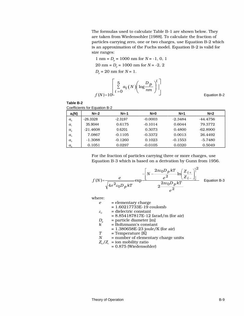
The formulas used to calculate Table B-1 are shown below. They are taken from Wiedensohler [1988]. To calculate the fraction of particles carrying zero, one or two charges, use Equation B-2 which is an approximation of the Fuchs model. Equation B-2 is valid for size ranges:
1 nm = Dp = 1000 nm for N = -1, 0, 1
20 nm = Dp = 1000 nm for N = -2, 2
Dp = 20 nm for N = 1.
( )
∑
==
5
0log
10)(i
i
nm
pDNia
Nf Equation B-2
Table B-2 Coefficients for Equation B-2
ai(N) N=-2 N=-1 N=0 N=1 N=2
a0 -26.3328 -2.3197 -0.0003 -2.3484 -44.4756
a1 35.9044 0.6175 -0.1014 0.6044 79.3772
a2 -21.4608 0.6201 0.3073 0.4800 -62.8900
a3 7.0867 -0.1105 -0.3372 0.0013 26.4492
a4 -1.3088 -0.1260 0.1023 -0.1553 -5.7480
a5 0.1051 0.0297 -0.0105 0.0320 0.5049
For the fraction of particles carrying three or more charges, use Equation B-3 which is based on a derivation by Gunn from 1956.
20
2
20
02 2
2
ln2
exp4
)(
e
kTD
Z
Z
e
kTDN
kTD
eNf
p
i
ip
pπε
πε
επ
−−
= −
+
Equation B-3
where: e = elementary charge = 1.60217733E-19 coulomb ε0 = dielectric constant = 8.854187817E-12 farad/m (for air) Dp = particle diameter [m] k = Boltzmann’s constant = 1.380658E-23 joule/K (for air) T = Temperature [K] N = number of elementary charge units Zi+/Zi- = ion mobility ratio = 0.875 (Wiedensohler)
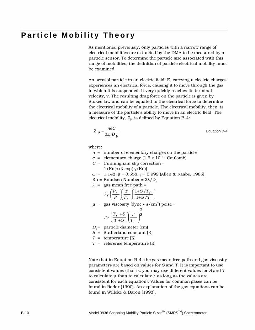
B-10 Model 3936 Scanning Mobility Particle SizerTM (SMPSTM) Spectrometer
P a r t i c l e M o b i l i t y T h e o r y As mentioned previously, only particles with a narrow range of electrical mobilities are extracted by the DMA to be measured by a particle sensor. To determine the particle size associated with this range of mobilities, the definition of particle electrical mobility must be examined. An aerosol particle in an electric field, E, carrying n electric charges experiences an electrical force, causing it to move through the gas in which it is suspended. It very quickly reaches its terminal velocity, v. The resulting drag force on the particle is given by Stokes law and can be equated to the electrical force to determine the electrical mobility of a particle. The electrical mobility, then, is a measure of the particle's ability to move in an electric field. The electrical mobility, Zp, is defined by Equation B-4:
pp D
neCZ
πµ3= Equation B-4
where:
n = number of elementary charges on the particle e = elementary charge (1.6 x 10⁻¹⁹ Coulomb) C = Cunningham slip correction = 1+Kn[α+β exp(-γ/Kn)] α = 1.142, β = 0.558, γ = 0.999 (Allen & Raabe, 1985) Kn = Knudsen Number = 2λ/Dp λ = gas mean free path =
++
TS
TS
T
T
P
P r
r
rr /1
/1λ
µ = gas viscosity (dyne • s/cm2) poise =
23
++
r
rr T
T
ST
STµ
Dp = particle diameter (cm) S = Sutherland constant [K] T = temperature [K] Tr = reference temperature [K]
Note that in Equation B-4, the gas mean free path and gas viscosity parameters are based on values for S and T. It is important to use consistent values (that is, you may use different values for S and T to calculate µ than to calculate λ as long as the values are consistent for each equation). Values for common gases can be found in Radar (1990). An explanation of the gas equations can be found in Willeke & Baron (1993).
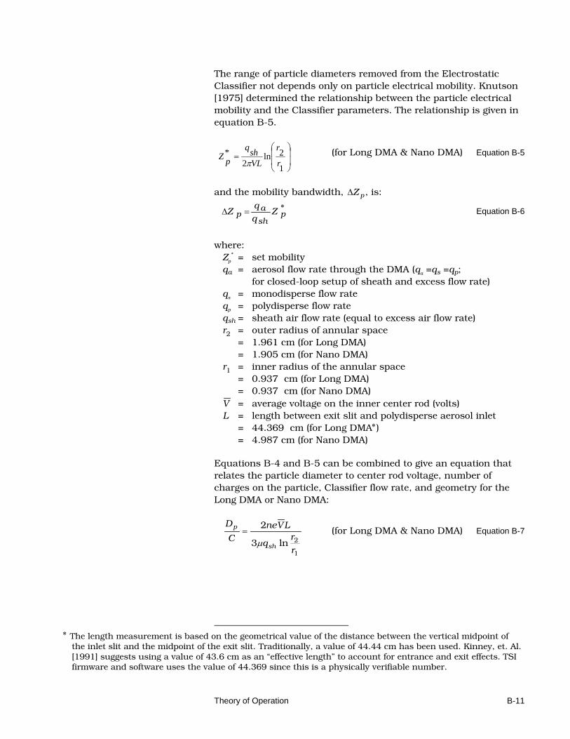
Theory of Operation B-11
The range of particle diameters removed from the Electrostatic Classifier not depends only on particle electrical mobility. Knutson [1975] determined the relationship between the particle electrical mobility and the Classifier parameters. The relationship is given in equation B-5.
=
1
2ln2
*r
r
VLshq
pZπ
(for Long DMA & Nano DMA) Equation B-5
and the mobility bandwidth, ∆Z p , is:
*p
sh
ap Z
q
qZ =∆ Equation B-6
where:
Zp
* = set mobility qa = aerosol flow rate through the DMA (qa =qs =qp; for closed-loop setup of sheath and excess flow rate) qs = monodisperse flow rate qp = polydisperse flow rate qsh = sheath air flow rate (equal to excess air flow rate) r2 = outer radius of annular space = 1.961 cm (for Long DMA) = 1.905 cm (for Nano DMA) r1 = inner radius of the annular space = 0.937 cm (for Long DMA) = 0.937 cm (for Nano DMA) V = average voltage on the inner center rod (volts) L = length between exit slit and polydisperse aerosol inlet = 44.369 cm (for Long DMA∗) = 4.987 cm (for Nano DMA)
Equations B-4 and B-5 can be combined to give an equation that relates the particle diameter to center rod voltage, number of charges on the particle, Classifier flow rate, and geometry for the Long DMA or Nano DMA:
1
2ln3
2
r
rq
LVne
C
D
sh
p
µ= (for Long DMA & Nano DMA) Equation B-7
∗ The length measurement is based on the geometrical value of the distance between the vertical midpoint of
the inlet slit and the midpoint of the exit slit. Traditionally, a value of 44.44 cm has been used. Kinney, et. Al. [1991] suggests using a value of 43.6 cm as an “effective length” to account for entrance and exit effects. TSI firmware and software uses the value of 44.369 since this is a physically verifiable number.
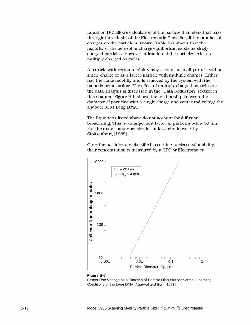
B-12 Model 3936 Scanning Mobility Particle SizerTM (SMPSTM) Spectrometer
Equation B-7 allows calculation of the particle diameters that pass through the exit slit of the Electrostatic Classifier, if the number of charges on the particle is known. Table B-1 shows that the majority of the aerosol in charge equilibrium exists as singly charged particles. However, a fraction of the particles exist as multiply charged particles. A particle with certain mobility may exist as a small particle with a single charge or as a larger particle with multiple charges. Either has the same mobility and is removed by the system with the monodisperse airflow. The effect of multiply charged particles on the data analysis is discussed in the “Data Reduction” section in this chapter. Figure B-6 shows the relationship between the diameter of particles with a single charge and center rod voltage for a Model 3081 Long DMA. The Equations listed above do not account for diffusion broadening. This is an important factor in particles below 50 nm. For the more comprehensive formulas, refer to work by Stoltzenburg [1988]. Once the particles are classified according to electrical mobility, their concentration is measured by a CPC or Electrometer.
q = 20 lpmq
10000
1000
100
100.001 0.01 0.1 1
Particle Diameter, Dp, µm
sh = qa < 4 lpms
Co
llect
or
Ro
d V
olt
age
V, V
olt
s
Figure B-6 Center Rod Voltage as a Function of Particle Diameter for Normal Operating Conditions of the Long DMA [Agarwal and Sem, 1978]
Theory of Operation B-13
C o n d e n s a t i o n P a r t i c l e C o u n t e r There are several models of CPCs: Model 3772, 3775, 3776, 3010, 3022A, 3025A CPCs, 3782, 3785, and 3786 WCPCs. Model 3782, 3785 and 3786 WCPCs use water as the condensing fluid. The rest of the CPCs use butanol as the condensing fluid. All CPCs are capable of interfacing with the Electrostatic Classifier to form an SMPS™ spectrometer. Refer to the individual CPC instruction manuals for the theory of operation of the CPCs.
CPC Theory The mechanism used to grow particles in the CPC is heterogeneous condensation, whereby particle growth is promoted by the presence of condensation nuclei. The CPC uses this mechanism to measure the number concentration of submicrometer aerosol particles. The saturation ratio of the condensing vapor determines the smallest particle size detected by the CPC. The saturation ratio is defined as the actual vapor partial pressure, p, divided by the saturation vapor pressure, ps, at a given temperature. The condensing vapor is butyl alcohol for 3772, 3775, 3776, 3010, 3022A, and 3025A CPCs. In 3782, 3785, and 3786 WCPC, the condensing vapor is water. The relationship between the saturation ratio and the minimal particle size is controlled by the Kelvin equation:
[ ]*/4exp/ RTdMpp s ρσ= Equation B-8
where: σ = the surface tension M = molecular weight ρ = the density of the liquid d* = the Kelvin diameter. R = universal gas constant T = absolute temperature The Kelvin diameter is the droplet diameter that will neither grow nor evaporate at the saturation ratio p/ps. For every droplet size there is a saturation ratio that will exactly maintain the particle size. If the saturation ratio is too small, the particle evaporates; if it is too great, the particle grows.
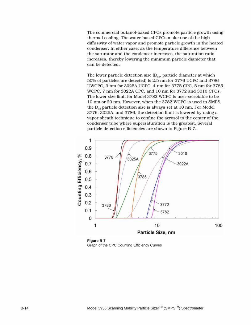
B-14 Model 3936 Scanning Mobility Particle SizerTM (SMPSTM) Spectrometer
The commercial butanol-based CPCs promote particle growth using thermal cooling. The water-based CPCs make use of the high diffusivity of water vapor and promote particle growth in the heated condenser. In either case, as the temperature difference between the saturator and the condenser increases, the saturation ratio increases, thereby lowering the minimum particle diameter that can be detected. The lower particle detection size (D50, particle diameter at which 50% of particles are detected) is 2.5 nm for 3776 UCPC and 3786 UWCPC, 3 nm for 3025A UCPC, 4 nm for 3775 CPC, 5 nm for 3785 WCPC, 7 nm for 3022A CPC, and 10 nm for 3772 and 3010 CPCs. The lower size limit for Model 3782 WCPC is user-selectable to be 10 nm or 20 nm. However, when the 3782 WCPC is used in SMPS, the D50 particle detection size is always set at 10 nm. For Model 3776, 3025A, and 3786, the detection limit is lowered by using a vapor sheath technique to confine the aerosol to the center of the condenser tube where supersaturation is the greatest. Several particle detection efficiencies are shown in Figure B-7.
Figure B-7 Graph of the CPC Counting Efficiency Curves
Theory of Operation B-15
Particle Counting Once the particles have grown to an optically detectable size (typically, 2 to 3 micrometers), they pass through a light beam and scatter light onto a photodetector. The calculation of particle concentration is different for each CPC, but all models operate in the single-particle count mode at concentrations below a certain value. The upper concentration limit for single-count mode is 10,000 particles/cm3 for 3772, 3010, and 3022A CPCs, 99,900 particles/cm3 for 3025A UCPC, 50,000 particles/cm3 for 3775 CPC and 3782 WCPC, 20,000 particles/cm3 for 3785 WCPC, 100,000 particles/cm3 for 3786 UWCPC, and 300,000 particles/cm3 for 3776 UCPC. The 3775, 3022A CPC and 3785 WCPC also operate in photometric mode based on photometric calibration up to 107 particles/cm3. It is important to understand the errors associated with the single-count mode to obtain accurate results from the SMPS™ spectrometer.
In the single-count mode, the pulse of light scattered by each particle is counted separately and the concentration is computed from the frequency of pulses. In this mode, there is error due to particle coincidence. Error is most important at the upper end of the count mode, Model 3022A, 3025A CPCs. 3782, 3785, and 3786 WCPCs use live-time counting for the last decade of the single count mode to automatically account for coincidence. Model 3772, 3775, and 3776 CPC use continuous live-time correction throughout the single count mode. The correction is minimal in single count mode because of the low concentration. The accuracy of the concentration reading is limited by statistical error at the lower end of the count mode. As the total number of particles counted in each particle size channel decreases, the uncertainty in the particle count increases. The statistical uncertainty, σ, is related to the total count, N, through the equation:
σ = N
N Equation B-9
where N is the particle count in a particle size channel. It can be seen from equation B-9, that the statistical error can be reduced by increasing the number of particles detected. In the SMPS™ program, this can be accomplished by increasing Up scan time, using multiple scans per sample, using a higher-flow rate CPC (such as a Model 3010, 3772, or 3785), or using a lower resolution to view the data.
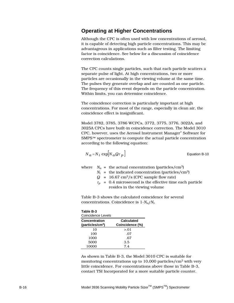
B-16 Model 3936 Scanning Mobility Particle SizerTM (SMPSTM) Spectrometer
Operating at Higher Concentrations Although the CPC is often used with low concentrations of aerosol, it is capable of detecting high particle concentrations. This may be advantageous in applications such as filter testing. The limiting factor is coincidence. See below for a discussion of coincidence correction calculations. The CPC counts single particles, such that each particle scatters a separate pulse of light. At high concentrations, two or more particles are occasionally in the viewing volume at the same time. The pulses they generate overlap and are counted as one particle. The frequency of this event depends on the particle concentration. Within limits, you can determine coincidence.
The coincidence correction is particularly important at high concentrations. For most of the range, especially in clean air, the coincidence effect is insignificant. Model 3782, 3785, 3786 WCPCs, 3772, 3775, 3776, 3022A, and 3025A CPCs have built-in coincidence correction. The Model 3010 CPC, however, uses the Aerosol Instrument Manager® Software for SMPS™ spectrometer to compute the actual particle concentration according to the following equation:
[ ]paia QNNN τexp= Equation B-10
where Na = the actual concentration (particles/cm3) Ni = the indicated concentration (particles/cm3) Q = 16.67 cm3/s (CPC sample flow rate) τp = 0.4 microsecond is the effective time each particle
resides in the viewing volume Table B-3 shows the calculated coincidence for several concentrations. Coincidence is 1-Na/Ni. Table B-3 Coincidence Levels
Concentration Calculated (particles/cm3) Coincidence (%) 10 >.01 100 .07 1000 .67 5000 3.5 10000 7.4
As shown in Table B-3, the Model 3010 CPC is suitable for monitoring concentrations up to 10,000 particles/cm3 with very little coincidence. For concentrations above those in Table B-3, contact TSI Incorporated for a more suitable particle counter.
Theory of Operation B-17
!
C a u t i o n At concentrations above 10,000, the Model 3010 CPC display flashes in the concentration mode (PT/CM3). If this occurs, the number of particles shown on the display could be substantially lower than the actual concentration.
T h e D a t a M e a s u r e m e n t P r o c e s s Aerosol Instrument Manager® Software for SMPS™ spectrometer and the microcomputer tie the Electrostatic Classifier, the impactor, and the Condensation Particle Counter (CPC) together to form the SMPS™ spectrometer. Refer to the Aerosol Instrument Manager Software for SMPS™ Instruction Manual. When the computer executes the Run command, the computer sends the CPC scan parameter data based on the selections entered under the Hardware Setup menu. After parameter data is sent, a command is sent to the CPC to begin the sample. The CPC uses its analog output port to control the Differential Mobility Analyzer (DMA) rod voltage in the Classifier. The CPC counts the particles leaving the DMA and sends the count data to the computer every tenth of a second. The Model 3785 WCPC, 3775 and 3022A CPCs use a photometric mode for concentrations greater than 10,000, 50,000, and 10,000 particles/cm3, respectively. So when the CPC is in photometric mode, the count value returned to the computer is calculated based on the concentration of particles measured. Since the photometric mode of the Model 3785 WCPC, 3775 or 3022A CPC in the SMPS setup is updated only once per second, the granularity of the data is increased for high particle concentrations. During the time the analyzer rod voltage is increasing (the Up scan), particles leaving the DMA are increasing in size. Their actual size depends on the electrical field they passed through within the DMA. The raw particle counts detected by the CPC are stored in an internal computer array. The computer bins (maps) the particle count data into particle-size channels (64 channels per decade of particle size) based on their mobility and with the assumption that each particle has a single charge. This data is used for the raw count data graphs and tables.
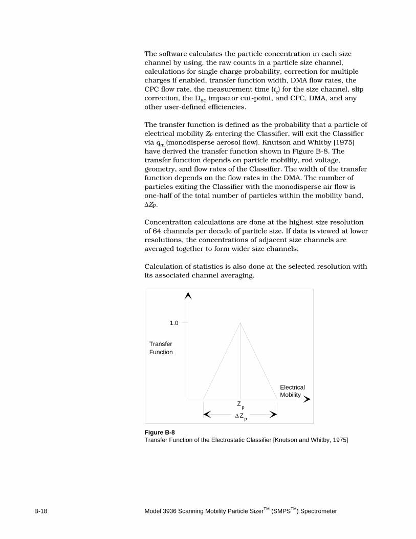
B-18 Model 3936 Scanning Mobility Particle SizerTM (SMPSTM) Spectrometer
The software calculates the particle concentration in each size channel by using, the raw counts in a particle size channel, calculations for single charge probability, correction for multiple charges if enabled, transfer function width, DMA flow rates, the CPC flow rate, the measurement time (tc) for the size channel, slip correction, the D50 impactor cut-point, and CPC, DMA, and any other user-defined efficiencies. The transfer function is defined as the probability that a particle of electrical mobility Zp entering the Classifier, will exit the Classifier via qm (monodisperse aerosol flow). Knutson and Whitby [1975] have derived the transfer function shown in Figure B-8. The transfer function depends on particle mobility, rod voltage, geometry, and flow rates of the Classifier. The width of the transfer function depends on the flow rates in the DMA. The number of particles exiting the Classifier with the monodisperse air flow is one-half of the total number of particles within the mobility band, ∆Zp. Concentration calculations are done at the highest size resolution of 64 channels per decade of particle size. If data is viewed at lower resolutions, the concentrations of adjacent size channels are averaged together to form wider size channels. Calculation of statistics is also done at the selected resolution with its associated channel averaging.
Zp
∆
Zp
ElectricalMobility
1.0
TransferFunction
Figure B-8 Transfer Function of the Electrostatic Classifier [Knutson and Whitby, 1975]
Theory of Operation B-19
R e f e r e n c e s Adachi, M., K. Okuyama and Y. Kousaka [1985] “Electrical Neutralization of Charged Aerosol Particles by Bipolar Ions,” Journal of Chemical Engineering, Japan, 16:229. Agarwal J.K., and G.J. Sem [1978] “Generating Submicron Monodisperse Aerosols for Instrument Calibrations,” TSI Quarterly, May/June, p 5, TSI Incorporated, St. Paul, MN. Blackford, D.B., and G. Simons [1986] “Particle Size Analysis of Carbon Black,” TSI Incorporated, St. Paul, MN. Presented at Fine Particle Society Annual Meeting, San Francisco, CA, July. (Unpublished) Blackford D.B., K.J. Belling, and G.J. Sem [1987] “A New Method for Measuring Nonvolatile Residue for Ultrapure Solvents,” Journal of Environmental Sciences, July/August, pp. 43–47. Caldow R.C., M.R. Palmer, and F.R. Quant [1992] “Performance of the TSI Model 3010 Condensation Particle Counter,” paper presented at the American Association for Aerosol Research Eleventh Annual Meeting, San Francisco, CA (TSI paper A83). Fissan, H.J., C. Helsper, and H.J. Thielen [1983] “Determination of Particle Size Distribution by Means of an Electrostatic Classifier,” Journal of Aerosol Science, 14:354. Fuchs, N.A. [1963] “On the Stationary Charge Distribution on Aerosol Particles in a Bipolar Ionic Atmosphere,” Geophys. Pura Appl., 56:185. Hering S.V. and M.R. Stolzenburg [2004] “Continuous, Laminar Flow Water-based Particle Condensation Device and Method,” US Patent 6,712,881, issued March 30, 2004. Hering, S.V. and M.R. Stolzenburg [2005] “A Method for Particle Size Amplification by Water Condensation in a Laminar, Thermally Diffusive Flow,” Aerosol Science and Technology, 39:428-436. Hering, S.V., M.R. Stolzenburg, F.R. Quant, D.R. Oberreit, and P.B. Keady [2005] “A Laminar-flow, Water-Based Condensation Particle Counter (WCPC),” Aerosol Science and Technology, 39:659-672.
B-20 Model 3936 Scanning Mobility Particle SizerTM (SMPSTM) Spectrometer
Hewitt, G.W. [1957] Trans. Am. Inst. Elect. Engrs., 76:300. Hinds, W.C. [1982] Aerosol Technology: Properties, Behavior, and Measurement of Airborne Particles, New York:John Wiley & Sons, p. 114. Hoppel, W.A. [1978] Journal of Aerosol Sci. 9:41. Hussin, A., H.G. Scheibel, K.H. Becker, and J. Porstendörfer [1983] “Bipolar Diffusion Charging of Aerosol Particles I: Experimental Results Within the Diameter Range of 4–30 nm.” Journal of Aerosol Science, 14:671.
Keady P.B., F.R. Quant, and G.J. Sem [1983] “Differential Mobility Particle Sizer: a New Instrument for High-Resolution Aerosol Size Distribution Measurement Below 1 µm.” TSI Incorporated, St. Paul, MN, April/June. Keady, P.B., F.R. Quant, and G.J. Sem [1984] “Automated Differential Mobility Particle Sizer” Aerosols, TSI Incorporated, St. Paul, MN. In proceedings for the 1st Int'l Aerosol Conference, Minneapolis, MN, B.Y.H. Liu, D.Y.H. Pui, and H. Fissan, ed. New York: Elsevier Science Publishing, pp. 71-74. Kesten, J., A. Reineking, and J. Porstendorfer [1991] “Calibration of a TSI Model 3025 Ultrafine Condensation Particle Counter,” Journal of Aerosol Science and Technology, 15:107. Kinney, P.D., D.Y.H. Pui, G.W. Mulholland, and N.P. Breyer [1991] “Use of the Electrostatic Classification Method to Size 0.1 µm SRM Particles—A Feasibility Study,” Journal of Research of the National Institute of Standards and Technology, 96:147. Knutson E.O. and K.T. Whitby [1975] “Aerosol Classification by Electric Mobility: Apparatus Theory and Applications,” Journal of Aerosol Science, 6:443. Liu, B.Y.H., and D.Y.H. Pui [1974] “Equilibrium Bipolar Charge Distribution,” Journal of Colloid Interface Science, 49:305. Liu, BYH and DYH Pui [1974] “Electrical Neutralization of Aerosols,” Journal of Aerosol Science, 5:465–472.
Theory of Operation B-21
Liu, B.Y.H., K.L. Rubow, and D.Y.H. Pui [1985] “Performance of HEPA and ULPA Filters.” Particle Technology Laboratory, University of Minnesota, 1985 Proceedings31st Annual Technical Meeting, Institute of Environmental Sciences, Las Vegas, NV, pp. 25-28, 30 Apr – 2 May. Liu W., S.L. Kaufman, G.J. Sem, and F.R. Quant [2004] “Material Effects on Threshold Counting Efficiency of TSI Model 3785 Water-based Condensation Particle Counter,” poster no. 6PD7, presented at the American Association for Aerosol Research 2004 Annual Conference, Atlanta, GA. Liu W., B.L. Osmondson, G.J. Sem, F.R. Quant, and D. Oberreit [2005], “Water-based Condensation Particle Counters for Environmental Monitoring of Ultrafine Particles,” platform presentation 8C-1, the Particulate Matter Supersites Program and Related Studies, An International Specialty Conference sponsored by American Association for Aerosol Research, Atlanta, GA. Plomp A. et al. [1982] Proceedings of the 10th Annual Gesellschaft für Aerosolforschung Conference Bologna, Italy. Pui, D.Y.H., and B.Y.H. Liu [1979] Technical paper: “Aerosol Generation and Calibration of Instruments,” Mechanical Engr. Dept. Univ of MN, May/June. Quant F.R., R.C. Caldow, G.J. Sem, and T.J. Addison [1992] “Performance of Condensation Particle Counters with Three Continuous-Flow Designs,” Journal of Aerosol Science, 23(S1):S405-S408 (TSI paper A79). Rohmann, H. [1923] Z. Phys. 18:188. Schürmann, G. [1986] “Measurement Techniques for HEPA-Filters in the Range of 0.03 µm–1 µm,” Proceedings of the 4th World Filtration Congress, Ostead, Belgium, April, pp. 14.25–14.32. Sem G.J., P.B. Keady, and F.R. Quant [1983] “High-Resolution Size Distribution Measurements of 0.01–15 µm Aerosol Particles,” TSI Incorporated, Proceedings Sixth World Congress on Air Quality, Paris, France, Vol 1, pp. 283-290, 16–20 May.
B-22 Model 3936 Scanning Mobility Particle SizerTM (SMPSTM) Spectrometer
Sem G.J. [2002] “Design and Performance Characteristics of Three Continuous-Flow Condensation Particle Counters: a Summary,” Atmospheric Research, 62:267-294. Wang, S. C., and R. C. Flagan [1989] “Scanning Electrical Mobility Spectrometer,” Division of Engineering and Applied Science, California Institute of Technology, Pasadena, CA 91125, pp.138-178. Wiedensohler, A., E. Lütkemeier, M. Feldpausch, and C. Helsper [1986] “Investigation of the Bipolar Charge Distribution at Various Gas Conditions,” Journal of Aerosol Science, 17:413. Wiedensohler, A., and H.J. Fissan [1988] “Aerosol Charging in High Purity Gases,” Journal of Aerosol Science, Vol. 19.
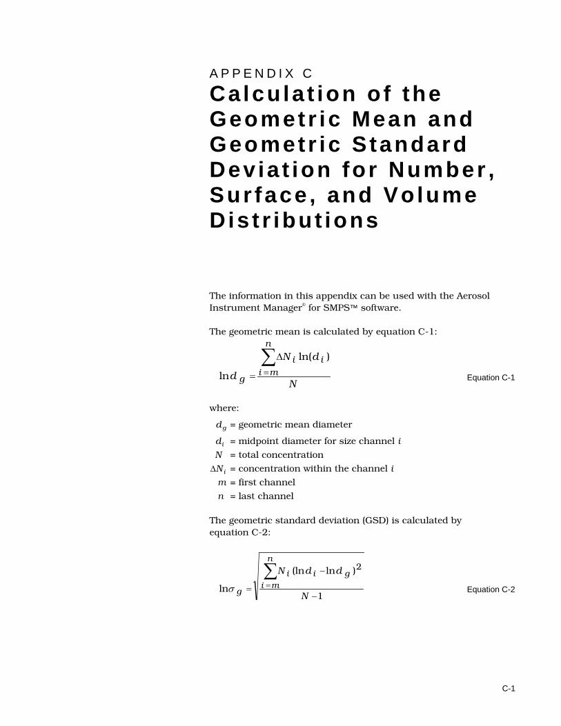
C-1
A P P E N D I X C Ca lcu la t ion of the Geometr ic Mean and Geometr ic Standard Devia t ion for Number , Sur face , and Volume Dist r ibut ions
The information in this appendix can be used with the Aerosol Instrument Manager® for SMPS™ software. The geometric mean is calculated by equation C-1:
N
dN
d
n
miii
g
∑=
∆
=
)ln(
ln Equation C-1
where:
dg = geometric mean diameter
di = midpoint diameter for size channel i
N = total concentration
∆Ni = concentration within the channel i
m = first channel
n = last channel The geometric standard deviation (GSD) is calculated by equation C-2:
1
)ln(ln
ln
2
−
−
=∑=
N
ddNn
migii
gσ Equation C-2

C-2 Model 3936 Scanning Mobility Particle SizerTM (SMPSTM) Spectrometer
where: dg = geometric mean diameter
di = midpoint diameter for size channel i
N = total concentration
∆Ni = concentration within the channel i
m = first channel
n = last channel
D-1
A P P E N D I X D Communication between Aerosol Instrument Manager® Software and the Electrostatic Classifier Model 3080
The Aerosol Instrument Manager® software version 8.2 is capable of communicating with the TSI Model 3080 Electrostatic Classifier. If you wish to use this communication, connect the computer to the classifier with a serial cable or USB-to-serial cable. The software sets the sheath flow rate and bypass flow rate in the classifier to values you select through the software. It sets the sheath flow mode to the appropriate value (dual or single blower) based on the selected flow rates and sets the voltage mode to analog. The software reads the sheath temperature and absolute pressure from the classifier before the start of data collection for each sample and uses those values to calculate gas viscosity and mean free path. If the software is not connected to the classifier it will use reference gas values that you can enter on a Properties dialog.
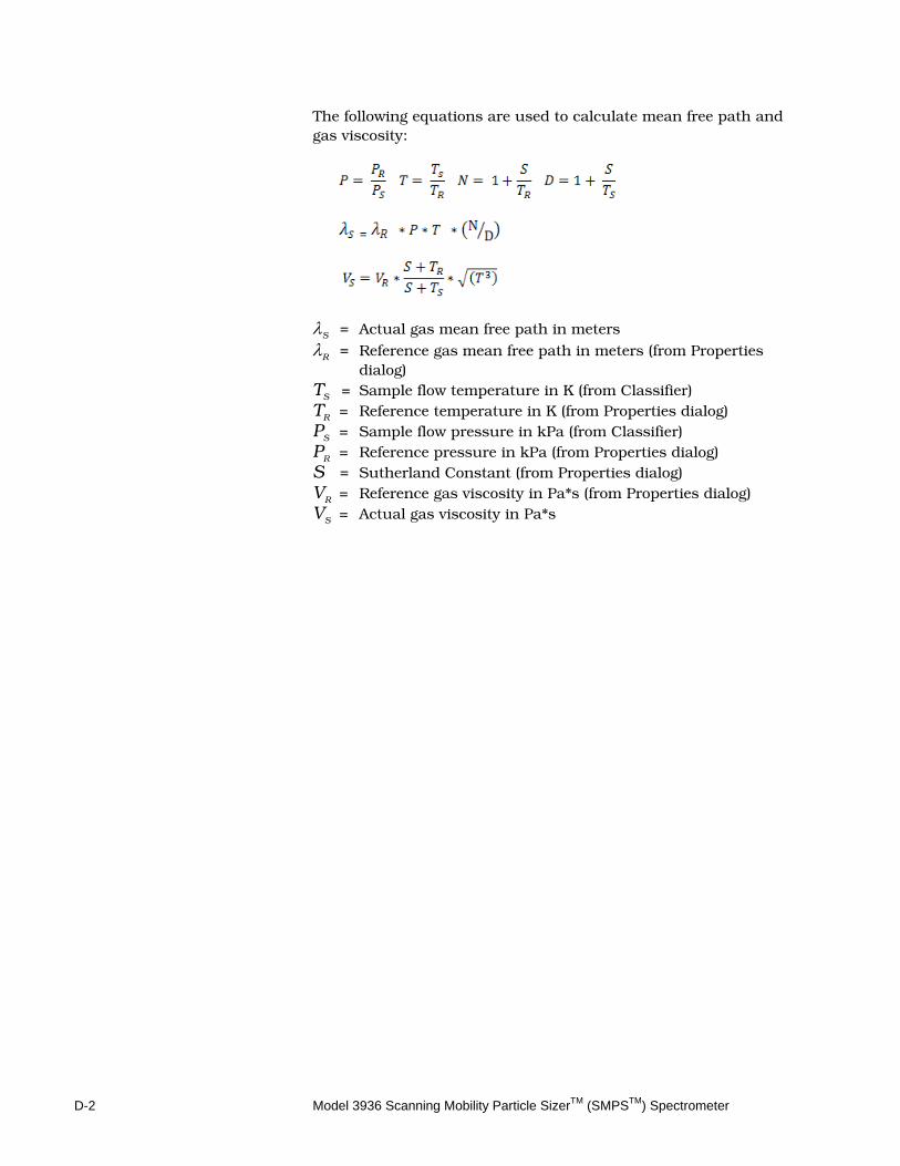
D-2 Model 3936 Scanning Mobility Particle SizerTM (SMPSTM) Spectrometer
The following equations are used to calculate mean free path and gas viscosity:
λS = Actual gas mean free path in meters λR = Reference gas mean free path in meters (from Properties
dialog) TS = Sample flow temperature in K (from Classifier) TR = Reference temperature in K (from Properties dialog) PS = Sample flow pressure in kPa (from Classifier) PR = Reference pressure in kPa (from Properties dialog) S = Sutherland Constant (from Properties dialog) VR = Reference gas viscosity in Pa*s (from Properties dialog) VS = Actual gas viscosity in Pa*s
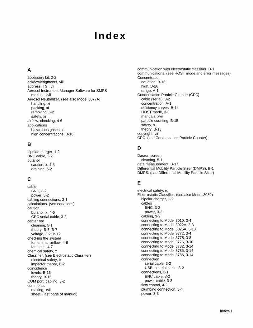
Index-1
Index
A accessory kit, 2-2 acknowledgments, viii address, TSI, vii Aerosol Instrument Manager Software for SMPS
manual, xvii Aerosol Neutralizer. (see also Model 3077A)
handling, xi packing, xi removing, 6-2 safety, xi
airflow, checking, 4-6 applications
hazardous gases, x high concentrations, B-16
B bipolar charger, 1-2 BNC cable, 3-2 butanol
caution, x, 4-5 draining, 6-2
C cable
BNC, 3-2 power, 3-2
cabling connections, 3-1 calculations. (see equations) caution
butanol, x, 4-5 CPC serial cable, 3-2
center rod cleaning, 5-1 theory, B-5, B-7 voltage, 3-2, B-12
checking the system for laminar airflow, 4-6 for leaks, 4-7
chemical safety, x Classifier. (see Electrostatic Classifier)
electrical safety, ix impactor theory, B-2
coincidence levels, B-16 theory, B-16
COM port, cabling, 3-2 comments
making, xviii sheet. (last page of manual)
communication with electrostatic classifier, D-1 communications. (see HOST mode and error messages) Concentration
equation, B-16 high, B-16 range, A-1
Condensation Particle Counter (CPC) cable (serial), 3-2 concentration, A-1 efficiency curves, B-14 HOST mode, 3-3 manuals, xvii particle counting, B-15 safety, x theory, B-13
copyright, vii CPC. (see Condensation Particle Counter)
D Dacron screen
cleaning, 5-1 data measurement, B-17 Differential Mobility Particle Sizer (DMPS), B-1 DMPS. (see Differential Mobility Particle Sizer)
E electrical safety, ix Electrostatic Classifier. (see also Model 3080)
bipolar charger, 1-2 cables
BNC, 3-2 power, 3-2
cabling, 3-2 connecting to Model 3010, 3-4 connecting to Model 3022A, 3-8 connecting to Model 3025A, 3-10 connecting to Model 3772, 3-4 connecting to Model 3775, 3-8 connecting to Model 3776, 3-10 connecting to Model 3782, 3-14 connecting to Model 3785, 3-14 connecting to Model 3786, 3-14 connection
serial cable, 3-2 USB to serial cable, 3-2
connections, 3-1 BNC cable, 3-2 power cable, 3-2
flow control, 4-2 plumbing connection, 3-4 power, 3-3

Index-2 Model 3936 Scanning Mobility Particle SizerTM (SMPSTM) Spectrometer
Electrostatic Classifier. (see also Model 3080) (continued) safety, xi setting flow rates, 4-2 specifications, A-1 theory of operation, B-4 transfer function, B-18
equations concentration, B-16 cut-point diameter, B-4 electrical mobility, B-10 geometric mean and geometric standard deviation, C-1 Kelvin, B-13 statistical uncertainty, B-15
F fax number, vii filter, 5-1 filter cartridge
replacing, 5-1 flow control, 4-2 flow rate
selecting, 4-2 setting, 4-6 specifications, A-1
flowmeter impactor as a, 4-5 troubleshooting, 5-2
G gas viscosity
equation, D-2 gases, warning, x geometric mean, C-1 geometric standard deviation (GSD), C-1
H hazardous gases (warning), x history
manual, vi SMPS spectrometer, B-1
HOST mode, 3-3, 4-1
I–J impactor
as a flowmeter, 4-5 cut-point, B-3 orifice size, 4-5 theory, B-2 typical operation, 3-4
impactor nozzle cleaning, 5-1
Inlet Impactor packing list, 2-2
Interface Pack packing list, 2-2
K Kelvin diameter, B-13
L labels (instrument), xi laser safety, ix leak testing, 4-6, 5-3 literature (manuals), xvii
M maintenance, 5-1
recommendations, 5-1 schedule, 5-1
manual copyright, vii history, vi part number, vii purpose, xvii related product, xvii
mean free path equation, D-2
Microsoft Windows registered trademark, viii
mobility bandwidth, B-11 equation, B-10 table, B-8
Model 3010 analog output, 3-3 connecting to Classifier, 3-4 electrical safety, ix filter cartridge, 5-2 laser safety, ix manual, xvii plumbing connection, 3-4 theory of operation, B-13 with Long DMA, 3-6, 3-7 with Nano DMA, 3-4, 3-5, 3-6
Model 3022A configuration mode, 3-3 connecting to Classifier, 3-8 electrical safety, ix filter cartridge, 5-2 laser safety, ix manual, xviii theory of operation, B-13 with Long DMA, 3-9, 3-10 with Nano DMA, 3-8, 3-9
Model 3025A configuration mode, 3-3 connecting to Classifier, 3-10 electrical safety, ix filter cartridge, 5-2 laser safety, ix manual, xviii theory of operation, B-13 with Long DMA, 3-12, 3-13 with Nano DMA, 3-11, 3-12
Model 3071, 3-4

Index Index-3
Model 3071A, 3-4 Model 3077A
cleaning, 5-1 Model 3080
flow control, 4-2 manual, xvii operating hardware, 4-1 overpressure mode, 3-4 radiation safety, xi underpressure mode, 3-4
Model 3080 Classifier communication with software, D-1
Model 3081 Long DMA electrical safety, ix with Model 3010, 3-6 with Model 3022A, 3-9 with Model 3025A, 3-12 with Model 3772, 3-6 with Model 3775, 3-9 with Model 3776, 3-12 with Model 3782, 3-15 with Model 3785, 3-15 with Model 3786, 3-15
Model 3085 Nano DMA electrical safety, ix photograph, 1-1 with Model 3010, 3-4 with Model 3022A, 3-8 with Model 3025A, 3-11 with Model 3772, 3-4 with Model 3775, 3-8 with Model 3776, 3-11 with Model 3782, 3-14 with Model 3785, 3-14 with Model 3786, 3-14
Model 3772 connecting to Classifier, 3-4 filter cartridge, 5-2 manual, xvii plumbing connection, 3-4 theory of operation, B-13 with Long DMA, 3-6, 3-7 with Nano DMA, 3-4, 3-5
Model 3775 connecting to Classifier, 3-8 filter cartridge, 5-2 manual, xvii theory of operation, B-13 with Long DMA, 3-9, 3-10 with Nano DMA, 3-8
Model 3776 connecting to Classifier, 3-10 filter cartridge, 5-2 theory of operation, B-13 with Long DMA, 3-12, 3-13 with Nano DMA, 3-11
Model 3782 connecting to Classifier, 3-14 electrical safety, ix filter cartridge, 5-2 laser safety, ix manual, xvii
Model 3782 (continued) theory of operation, B-13 wick, 5-2 with Long DMA, 3-15 with Nano DMA, 3-14
Model 3785 connecting to Classifier, 3-14 electrical safety, ix filter cartridge, 5-2 laser safety, ix manual, xvii theory of operation, B-13 wick, 5-2 with Long DMA, 3-15 with Nano DMA, 3-14
Model 3786 connecting to Classifier, 3-14 electrical safety, ix filter cartridge, 5-2 laser safety, ix manual, xvii photograph, 1-1 theory of operation, B-13 wick, 5-2 with Long DMA, 3-15 with Nano DMA, 3-14
Model 3936 applications, 1-2 cabling connections, 3-1 components, 2-1 history, B-1 introduction, 1-1 laser safety, ix maintenance, 5-1
recommendations, 5-1 schedule, 5-1
operation, 1-2 packing lists, 2-1 photograph, 1-1 plumbing arrangement, 3-1 power sequence, 3-3 product description, 1-1 setting up hardware, 3-1 specifications, A-1 theory of operation, B-1 troubleshooting, 5-1, 5-2
system plumbing, 5-3 testing for leaks, 5-3
typical operation, 3-4 unpacking instructions, 2-2
N n-butyl alcohol. (see butanol) Neutralizer. (see also Aerosol Neutralizer)
O operation
typical mode, 3-4 overpressure mode, 4-6
definition, 3-4
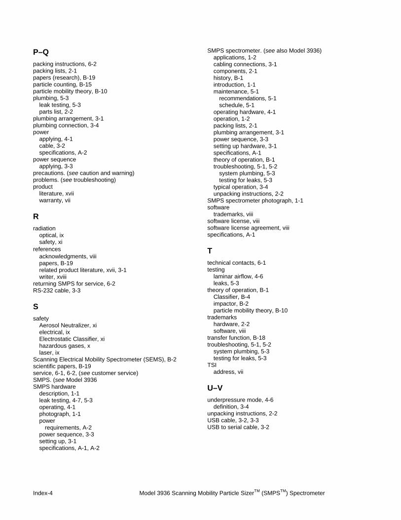
Index-4 Model 3936 Scanning Mobility Particle SizerTM (SMPSTM) Spectrometer
P–Q packing instructions, 6-2 packing lists, 2-1 papers (research), B-19 particle counting, B-15 particle mobility theory, B-10 plumbing, 5-3
leak testing, 5-3 parts list, 2-2
plumbing arrangement, 3-1 plumbing connection, 3-4 power
applying, 4-1 cable, 3-2 specifications, A-2
power sequence applying, 3-3
precautions. (see caution and warning) problems. (see troubleshooting) product
literature, xvii warranty, vii
R radiation
optical, ix safety, xi
references acknowledgments, viii papers, B-19 related product literature, xvii, 3-1 writer, xviii
returning SMPS for service, 6-2 RS-232 cable, 3-3
S safety
Aerosol Neutralizer, xi electrical, ix Electrostatic Classifier, xi hazardous gases, x laser, ix
Scanning Electrical Mobility Spectrometer (SEMS), B-2 scientific papers, B-19 service, 6-1, 6-2, (see customer service) SMPS. (see Model 3936 SMPS hardware
description, 1-1 leak testing, 4-7, 5-3 operating, 4-1 photograph, 1-1 power
requirements, A-2 power sequence, 3-3 setting up, 3-1 specifications, A-1, A-2
SMPS spectrometer. (see also Model 3936) applications, 1-2 cabling connections, 3-1 components, 2-1 history, B-1 introduction, 1-1 maintenance, 5-1
recommendations, 5-1 schedule, 5-1
operating hardware, 4-1 operation, 1-2 packing lists, 2-1 plumbing arrangement, 3-1 power sequence, 3-3 setting up hardware, 3-1 specifications, A-1 theory of operation, B-1 troubleshooting, 5-1, 5-2
system plumbing, 5-3 testing for leaks, 5-3
typical operation, 3-4 unpacking instructions, 2-2
SMPS spectrometer photograph, 1-1 software
trademarks, viii software license, viii software license agreement, viii specifications, A-1
T technical contacts, 6-1 testing
laminar airflow, 4-6 leaks, 5-3
theory of operation, B-1 Classifier, B-4 impactor, B-2 particle mobility theory, B-10
trademarks hardware, 2-2 software, viii
transfer function, B-18 troubleshooting, 5-1, 5-2
system plumbing, 5-3 testing for leaks, 5-3
TSI address, vii
U–V underpressure mode, 4-6
definition, 3-4 unpacking instructions, 2-2 USB cable, 3-2, 3-3 USB to serial cable, 3-2

Index Index-5
W–X–Y–Z warning
hazardous gases, x high voltage, x optical radiation, ix radiation, xi
Windows. (see Microsoft Windows)


Reader ’s Comments
Please help us improve our manuals by completing and returning this questionnaire to the address listed in the “About This Manual” section. Feel free to attach a separate sheet of comments. Manual Title Model 3936 Scanning Mobility Particle Sizer™ (SMPS™) Spectrometer
P/N 1933796 Rev. P 1. Was the manual easy to understand and use?
Yes No Please identify any problem area(s) ____________________________________________________________
_______________________________________________________________________________________________
_______________________________________________________________________________________________
2. Was there any incorrect or missing information? (please explain) ________________________________
_______________________________________________________________________________________________
_______________________________________________________________________________________________
3. Please rate the manual according to the following features:
Good Adequate Poor Readability Accuracy Completeness (is everything there?) Organization (finding what you need) Quality and number of illustrations Quality and number of examples
Comments: ___________________________________________________________________________________
_______________________________________________________________________________________________
_______________________________________________________________________________________________
4. Which part(s) of this manual did you find most helpful? ________________________________________
_______________________________________________________________________________________________
_______________________________________________________________________________________________
5. Rate your level of experience with the product:
Beginning Intermediate Expert
6. Please provide us with the following information:
Name ____________________________________ Address ________________________________________
Title __________________________________ ____________________________________
Company ________________________________ ________________________________________


TSI Incorporated – 500 Cardigan Road, Shoreview, MN 55126 U.S.A USA Tel: +1 800 874 2811 E-mail: [email protected] Website: www.tsi.com UK Tel: +44 149 4 459200 E-mail: [email protected] Website: www.tsiinc.co.uk France Tel: +33 491 11 87 64 E-mail: [email protected] Website: www.tsiinc.fr Germany Tel: +49 241 523030 E-mail: [email protected] Website: www.tsiinc.de India Tel: +91 80 41132470 E-mail: [email protected] China Tel: +86 10 8260 1595 E-mail: [email protected] Singapore Tel: +65 6595 6388 E-mail: [email protected] Contact your local TSI Distributor or visit our website www.tsi.com for more detailed specifications.
P/N 1933796 Rev P Copyright © 2010 by TSI Incorporated Printed in U.S.A.