Embed Size (px)
Citation preview
Industry Sector, IA&DT
SCE Training Curriculum Page 1 of 62 To be used only at Educational and R&D Facilities
TIA Portal Module 010-010, Edition 09/2012 Unrestricted / © Siemens AG 2012. All Rights Reserved SCE_EN_010-010_R1209_Startup Programming of the SIMATIC S7-1200
TIA Portal Module 010-010 Startup Programming of the SIMATIC S7-1200
SCE Training Curriculum
for Integrated Automation Solutions
Totally Integrated Automation (TIA) Siemens Automation Cooperates with Education
Industry Sector, IA&DT
SCE Training Curriculum Page 2 of 62 To be used only at Educational and R&D Facilities
TIA Portal Module 010-010, Edition 09/2012 Unrestricted / © Siemens AG 2012. All Rights Reserved SCE_EN_010-010_R1209_Startup Programming of the SIMATIC S7-1200
Matching SCE training packages for these training curriculums SIMATIC S7-1200 AC/DC/RELAY 6er "TIA Portal"
Order number: 6ES7214-1BE30-4AB3 SIMATIC S7-1200 DC/DC/DC 6er "TIA Portal"
Order number 6ES7214-1AE30-4AB3 SIMATIC S7-SW for Training STEP 7 BASIC V11 Upgrade (for S7-1200) 6er "TIA Portal"
Order number 6ES7822-0AA01-4YE0 Please note that these training packages are replaced with successor packages when necessary. An overview of the currently available SCE packages is provided under: siemens.com/sce/tp
Continued Training For regional Siemens SCE continued training, please contact your regional SCE contact person siemens.com/sce/contact
Additional information regarding SCE siemens.com/sce
Information regarding Usage This SCE training curriculum for the integrated automation solution Totally Integrated Automation (TIA) was prepared for the program "Siemens Automation Cooperates with Education (SCE)“ specifically for training purposes for public education facilities and R&D facilities. Siemens AG does not guarantee the contents. This document is to be used only for initial training on Siemens products/systems; i.e., it can be copied entirely or partially and given to those being trained for usage within the scope of their training. Passing on as well as copying this training curriculum and sharing its content is permitted within public training and advanced training facilities for training purposes. Exceptions require written permission by the Siemens AG contact person: Roland Scheuerer [email protected]. Offenders will be held liable. All rights including translation are reserved, particularly if a patent is granted or a utility model or design is registered. Usage for industrial customer courses is explicitly not permitted. We do not consent to the training curriculums being used commercially. We wish to thank the Michael Dziallas Engineering Corporation and all other involved persons for their support during the preparation of this training curriculum.
Industry Sector, IA&DT
SCE Training Curriculum Page 3 of 62 To be used only at Educational and R&D Facilities
TIA Portal Module 010-010, Edition 09/2012 Unrestricted / © Siemens AG 2012. All Rights Reserved SCE_EN_010-010_R1209_Startup Programming of the SIMATIC S7-1200
PAGE
Contents 1. Preface ....................................................................................................................................................... 4
2. Notes on Programming the SIMATIC S7-1200 .......................................................................................... 6
2.1 Automation System SIMATIC S7-1200 ...................................................................................................... 6
2.2 Programming Software STEP Professional V11 (TIA Portal V11) ............................................................. 6
3. Installing the Software STEP 7 Professional (TIA Portal V11) ................................................................... 7
3.1 Installing current Updates for STEP 7 Professional V11 (TIA-Portal V11 .................................................. 7
3.2 Update the hardware catalog in STEP 7 Professional V11 (TIA-Portal V11 with Hardware Support
Packages (HSP)................................................................................................................................................... 8
4. Connecting to the CPU by means of TCP/IP, and Resetting to Factory Setting ...................................... 14
5. What is a PLC and what are PLCs Used For? ......................................................................................... 22
5.1 What does the term PLC mean? .............................................................................................................. 22
5.2 How does the PLC Control the Process? ................................................................................................. 22
5.3 How does the PLC Get the Information about the Process States? ........................................................ 23
5.4 What is the Difference between Break Contact Elements and Make Contact Elements? ....................... 23
5.5 How does the SIMATIC S7-1200 Address Individual Input/Output Signals? ........................................... 24
5.6 How is the Program Processed in the PLC? ............................................................................................ 25
5.7 What do Logic Operations Look Like in the PLC Program? ..................................................................... 26
5.7.1 AND Operation ................................................................................................................................. 26
5.7.2 OR Operation ................................................................................................................................... 28
5.7.3 Negation ........................................................................................................................................... 29
5.8 How is the PLC Program generated? How does it get to the PLC’s memory? ........................................ 30
6. Configuring and Operating the SIMATIC S7-1200 ................................................................................... 31
7. Sample Task: Controlling a Press ............................................................................................................ 35
8. Programming the Press for the SIMATIC S7-1200 .................................................................................. 36
8.1. Portal View ........................................................................................................................................... 36
8.2. Project View ......................................................................................................................................... 37
Industry Sector, IA&DT
SCE Training Curriculum Page 4 of 62 To be used only at Educational and R&D Facilities
TIA Portal Module 010-010, Edition 09/2012 Unrestricted / © Siemens AG 2012. All Rights Reserved SCE_EN_010-010_R1209_Startup Programming of the SIMATIC S7-1200
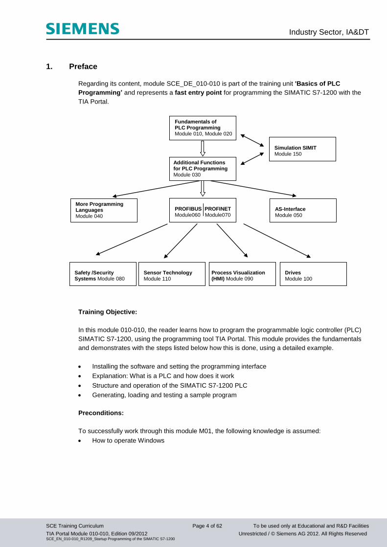
1. Preface
Regarding its content, module SCE_DE_010-010 is part of the training unit 'Basics of PLC
Programming’ and represents a fast entry point for programming the SIMATIC S7-1200 with the
TIA Portal.
Training Objective:
In this module 010-010, the reader learns how to program the programmable logic controller (PLC)
SIMATIC S7-1200, using the programming tool TIA Portal. This module provides the fundamentals
and demonstrates with the steps listed below how this is done, using a detailed example.
Installing the software and setting the programming interface
Explanation: What is a PLC and how does it work
Structure and operation of the SIMATIC S7-1200 PLC
Generating, loading and testing a sample program
Preconditions:
To successfully work through this module M01, the following knowledge is assumed:
How to operate Windows
Additional Functions for PLC Programming
Module 030
PROFIBUS PROFINET Module060 Module070
AS-Interface Module 050
Safety /Security Systems Module 080
Drives Module 100
Process Visualization (HMI) Module 090
Sensor Technology Module 110
Simulation SIMIT Module 150
More Programming Languages Module 040
Fundamentals of PLC Programming Module 010, Module 020
Industry Sector, IA&DT
SCE Training Curriculum Page 5 of 62 To be used only at Educational and R&D Facilities
TIA Portal Module 010-010, Edition 09/2012 Unrestricted / © Siemens AG 2012. All Rights Reserved SCE_EN_010-010_R1209_Startup Programming of the SIMATIC S7-1200
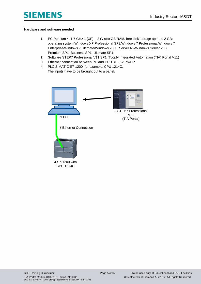
Hardware and software needed
1 PC Pentium 4, 1.7 GHz 1 (XP) – 2 (Vista) GB RAM, free disk storage approx. 2 GB;
operating system Windows XP Professional SP3/Windows 7 Professional/Windows 7
Enterprise/Windows 7 Ultimate/Windows 2003 Server R2/Windows Server 2008
Premium SP1, Business SP1, Ultimate SP1
2 Software STEP7 Professional V11 SP1 (Totally Integrated Automation (TIA) Portal V11)
3 Ethernet connection between PC and CPU 315F-2 PN/DP
4 PLC SIMATIC S7-1200; for example, CPU 1214C.
The inputs have to be brought out to a panel.
1 PC
2 STEP7 Professional
V11 (TIA Portal)
4 S7-1200 with
CPU 1214C
3 Ethernet Connection
Industry Sector, IA&DT
SCE Training Curriculum Page 6 of 62 To be used only at Educational and R&D Facilities
TIA Portal Module 010-010, Edition 09/2012 Unrestricted / © Siemens AG 2012. All Rights Reserved SCE_EN_010-010_R1209_Startup Programming of the SIMATIC S7-1200
2. Notes on Programming the SIMATIC S7-1200
2.1 Automation System SIMATIC S7-1200
The automation system SIMATIC S7-1200 is a modular mini-controller system for the lower and
medium performance range.
An extensive module spectrum is available for optimum adaptation to the automation task.
The S7 controller consists of a power supply, a CPU and input/output modules for digital and analog
signals. .
If needed, communication processors and function modules are added for special tasks such as step
motor control.
With the S7 program, the programmable logic controller (PLC) monitors and controls a machine or a
process, whereby the IO modules are polled in the S7 program by means of the input addresses (%I)
and addressed by means of output addresses (%Q).
The system is programmed with the software STEP 7.
2.2 Programming Software STEP Professional V11 (TIA Portal V11)
The software STEP 7 Professional V11 (TIA Portal V11) is the programming tool for the following
automation systems
- SIMATIC S7-1200
- SIMATIC S7-300
- SIMATIC S7-400
- SIMATIC WinAC
With STEP 7 Professional V11, the following functions can be utilized to automate a plant:
- Configuring and parameterizing the hardware
- Defining the communication
- Programming
- Testing, commissioning and service with the operating/diagnostic functions
- Documentation
- Generating the visual displays for the SIMATIC basic panels with the integrated WinCC Basic
- With additional WinCC packages, visual display solutions for PCs and other panels can be
prepared
All functions are supported with detailed online help.
Industry Sector, IA&DT
SCE Training Curriculum Page 7 of 62 To be used only at Educational and R&D Facilities
TIA Portal Module 010-010, Edition 09/2012 Unrestricted / © Siemens AG 2012. All Rights Reserved SCE_EN_010-010_R1209_Startup Programming of the SIMATIC S7-1200
3. Installing the Software STEP 7 Professional (TIA Portal V11)
STEP 7 Professional is supplied on a DVD.
To install STEP 7 Professional, do the following:
1. Insert the DVD of STEP 7 Basic Professional in the DVD drive.
2. The setup program is started automatically. If not, start it by double clicking on the file '
START.exe’.
3. The setup program guides you through the entire installation of STEP 7 Professional.
4. To utilize STEP 7 Professional, a license key is needed on your computer.
This license key can be transferred in the course of installation from a USB stick that is included to your
computer. Subsequently it is possible to move this license key to another data carriers using the
software ‘Automation License Manager’. This license key may also be located on another computer
and polled by means of a network.
3.1 Installing current Updates for STEP 7 Professional V11 (TIA-Portal V11
STEP 7 Professional V11 (TIAPortal V11) is updated frequently to optimally integrate new products; the
respective updates are made available on the Internet.
Here the link to the corresponding webpage:
http://support.automation.siemens.com/WW/view/en/59604410
From there, you can download upgrades to save them on your PC or laptop.
Installation then takes place as follows:
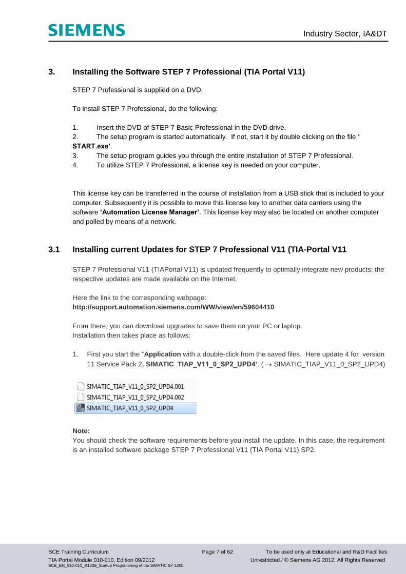
1. First you start the “Application with a double-click from the saved files. Here update 4 for version
11 Service Pack 2‚ SIMATIC_TIAP_V11_0_SP2_UPD4‘. ( SIMATIC_TIAP_V11_0_SP2_UPD4)
Note:
You should check the software requirements before you install the update. In this case, the requirement
is an installed software package STEP 7 Professional V11 (TIA Portal V11) SP2.
Industry Sector, IA&DT
SCE Training Curriculum Page 8 of 62 To be used only at Educational and R&D Facilities
TIA Portal Module 010-010, Edition 09/2012 Unrestricted / © Siemens AG 2012. All Rights Reserved SCE_EN_010-010_R1209_Startup Programming of the SIMATIC S7-1200
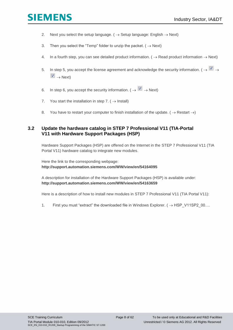
2. Next you select the setup language. ( Setup language: English Next)
3. Then you select the “Temp” folder to unzip the packet. ( Next)
4. In a fourth step, you can see detailed product information. ( Read product information Next)
5. In step 5, you accept the license agreement and acknowledge the security information. (
Next)
6. In step 6, you accept the security information. ( Next)
7. You start the installation in step 7. ( Install)
8. You have to restart your computer to finish installation of the update. ( Restart )
3.2 Update the hardware catalog in STEP 7 Professional V11 (TIA-Portal V11 with Hardware Support Packages (HSP)
Hardware Support Packages (HSP) are offered on the Internet in the STEP 7 Professional V11 (TIA
Portal V11) hardware catalog to integrate new modules.
Here the link to the corresponding webpage:
http://support.automation.siemens.com/WW/view/en/54164095
A description for installation of the Hardware Support Packages (HSP) is available under:
http://support.automation.siemens.com/WW/view/en/54163659
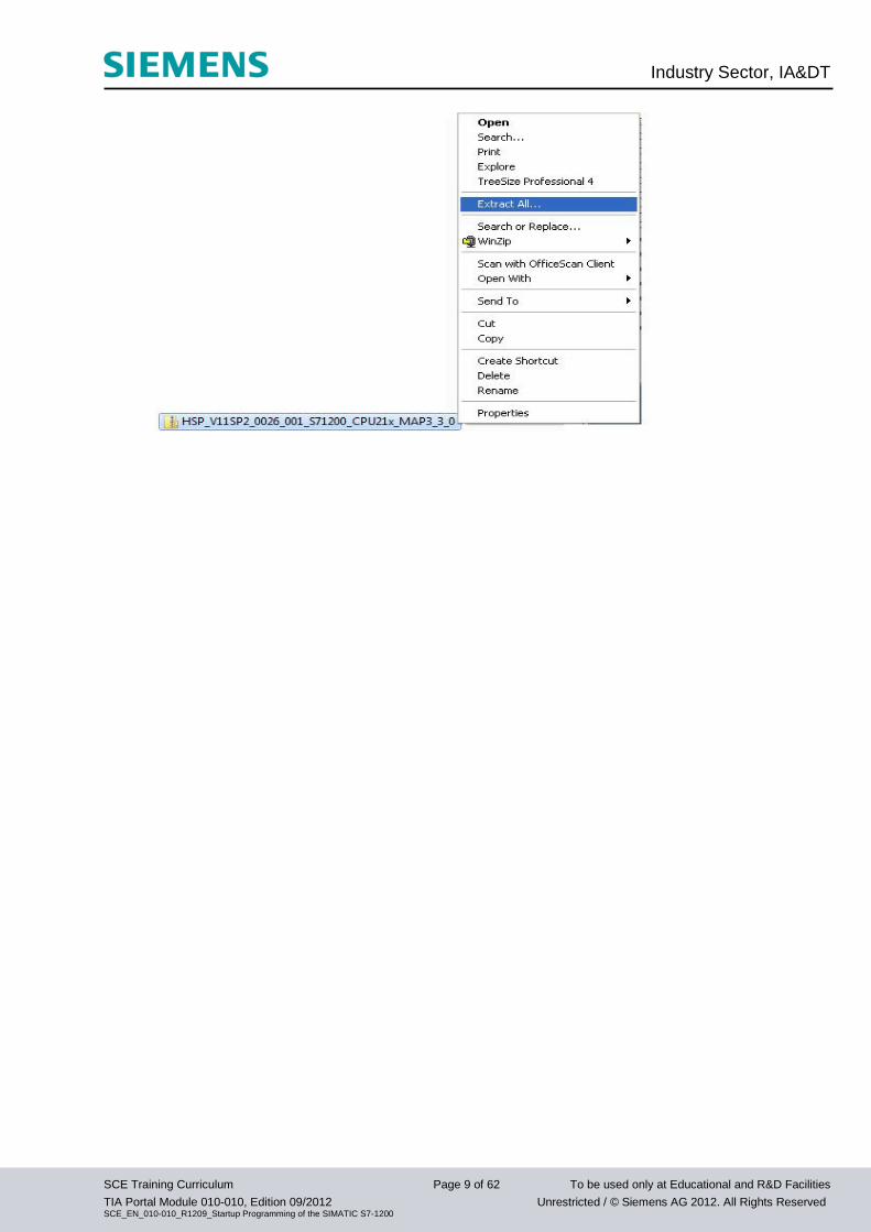
Here is a description of how to install new modules in STEP 7 Professional V11 (TIA Portal V11):
1. First you must “extract” the downloaded file in Windows Explorer. ( HSP_V11SP2_00….
Industry Sector, IA&DT
SCE Training Curriculum Page 9 of 62 To be used only at Educational and R&D Facilities
TIA Portal Module 010-010, Edition 09/2012 Unrestricted / © Siemens AG 2012. All Rights Reserved SCE_EN_010-010_R1209_Startup Programming of the SIMATIC S7-1200
Industry Sector, IA&DT
SCE Training Curriculum Page 10 of 62 To be used only at Educational and R&D Facilities
TIA Portal Module 010-010, Edition 09/2012 Unrestricted / © Siemens AG 2012. All Rights Reserved SCE_EN_010-010_R1209_Startup Programming of the SIMATIC S7-1200
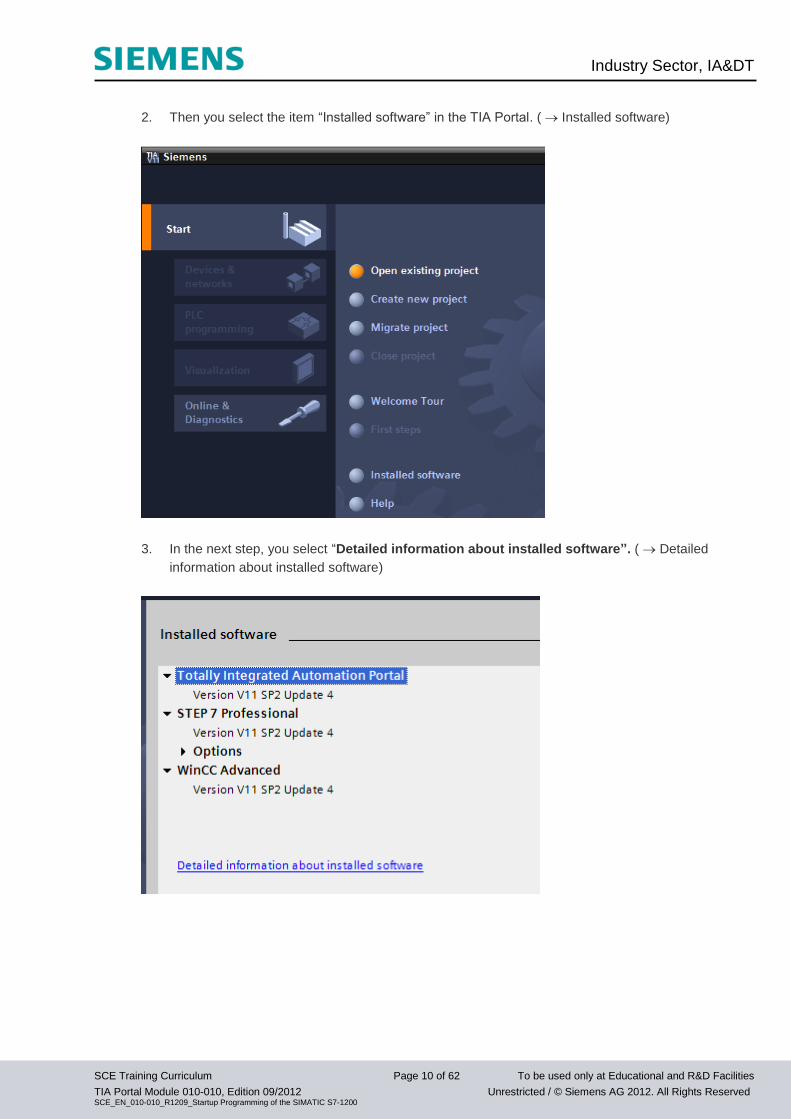
2. Then you select the item “Installed software” in the TIA Portal. ( Installed software)
3. In the next step, you select “Detailed information about installed software”. ( Detailed
information about installed software)
Industry Sector, IA&DT
SCE Training Curriculum Page 11 of 62 To be used only at Educational and R&D Facilities
TIA Portal Module 010-010, Edition 09/2012 Unrestricted / © Siemens AG 2012. All Rights Reserved SCE_EN_010-010_R1209_Startup Programming of the SIMATIC S7-1200
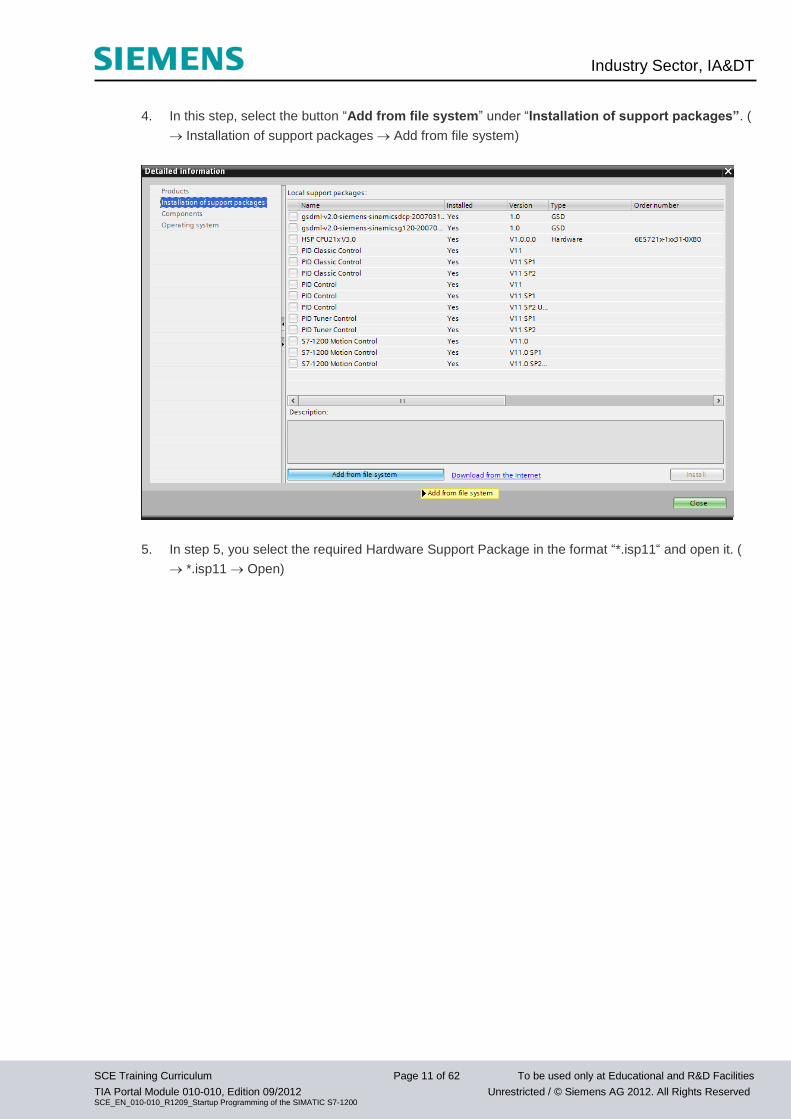
4. In this step, select the button “Add from file system” under “Installation of support packages”. (
Installation of support packages Add from file system)
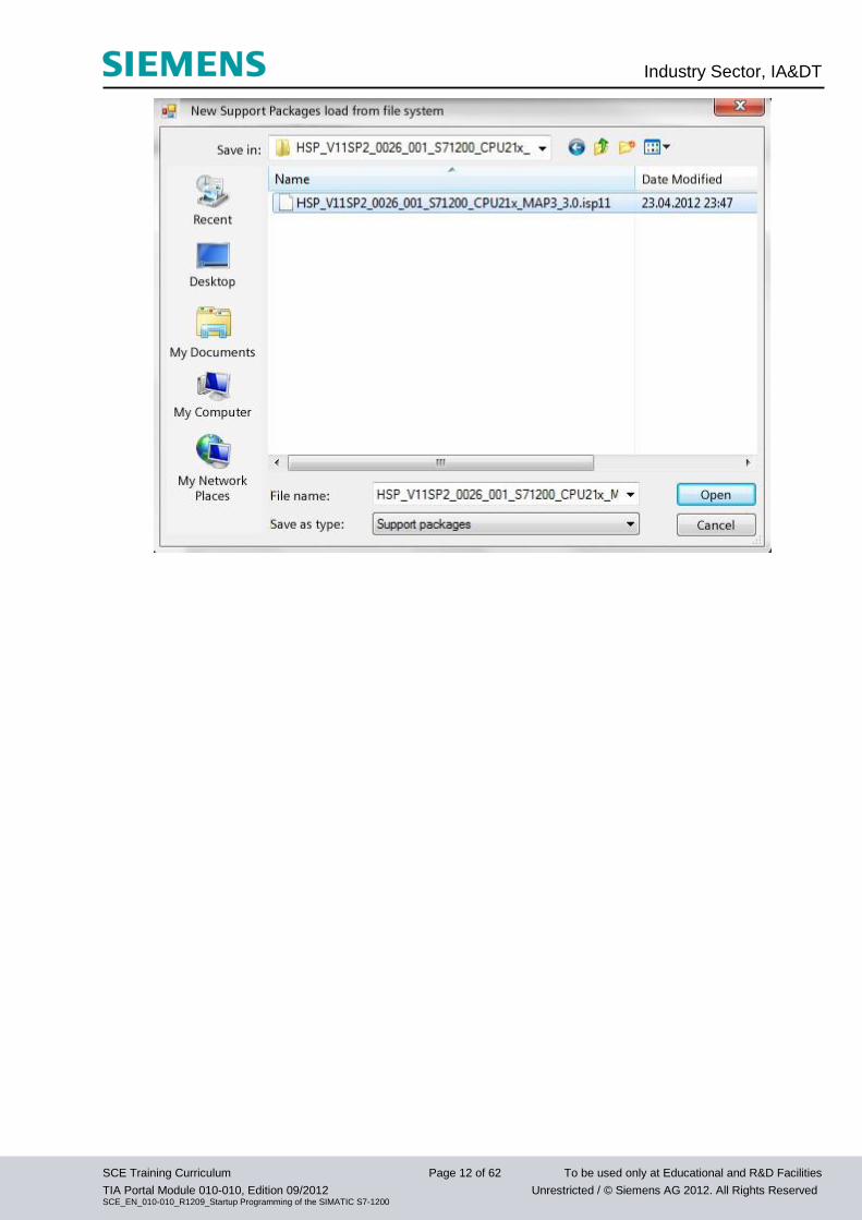
5. In step 5, you select the required Hardware Support Package in the format “*.isp11“ and open it. (
*.isp11 Open)
Industry Sector, IA&DT
SCE Training Curriculum Page 12 of 62 To be used only at Educational and R&D Facilities
TIA Portal Module 010-010, Edition 09/2012 Unrestricted / © Siemens AG 2012. All Rights Reserved SCE_EN_010-010_R1209_Startup Programming of the SIMATIC S7-1200
Industry Sector, IA&DT
SCE Training Curriculum Page 13 of 62 To be used only at Educational and R&D Facilities
TIA Portal Module 010-010, Edition 09/2012 Unrestricted / © Siemens AG 2012. All Rights Reserved SCE_EN_010-010_R1209_Startup Programming of the SIMATIC S7-1200
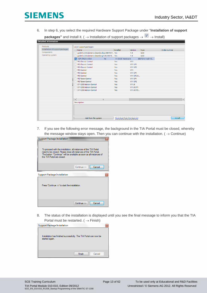
6. In step 6, you select the required Hardware Support Package under “Installation of support
packages” and install it. ( Installation of support packages Install)
7. If you see the following error message, the background in the TIA Portal must be closed, whereby
the message window stays open. Then you can continue with the installation. ( Continue)
8. The status of the installation is displayed until you see the final message to inform you that the TIA
Portal must be restarted. ( Finish)
Industry Sector, IA&DT
SCE Training Curriculum Page 14 of 62 To be used only at Educational and R&D Facilities
TIA Portal Module 010-010, Edition 09/2012 Unrestricted / © Siemens AG 2012. All Rights Reserved SCE_EN_010-010_R1209_Startup Programming of the SIMATIC S7-1200
4. Connecting to the CPU by means of TCP/IP, and Resetting to Factory Setting
To program the SIMATIC S7-1200 from the PC, the PG or a laptop, you need a TCP/IP connection.
For the PC and the SIMATIC S7-1200 to communicate with each other, it is important also that the IP
addresses of both devices match.
First, we show you how to set the computer’s IP address.
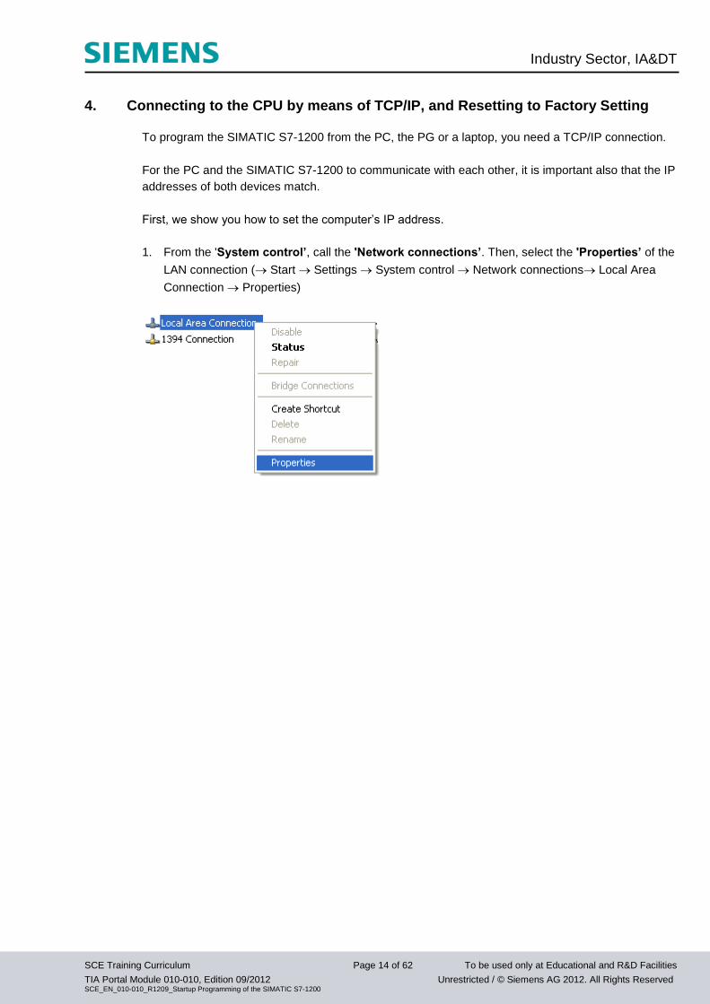
1. From the 'System control’, call the 'Network connections’. Then, select the 'Properties’ of the
LAN connection ( Start Settings System control Network connections Local Area
Connection Properties)
Industry Sector, IA&DT
SCE Training Curriculum Page 15 of 62 To be used only at Educational and R&D Facilities
TIA Portal Module 010-010, Edition 09/2012 Unrestricted / © Siemens AG 2012. All Rights Reserved SCE_EN_010-010_R1209_Startup Programming of the SIMATIC S7-1200
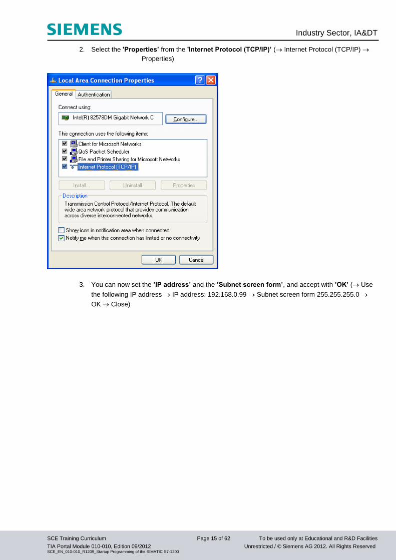
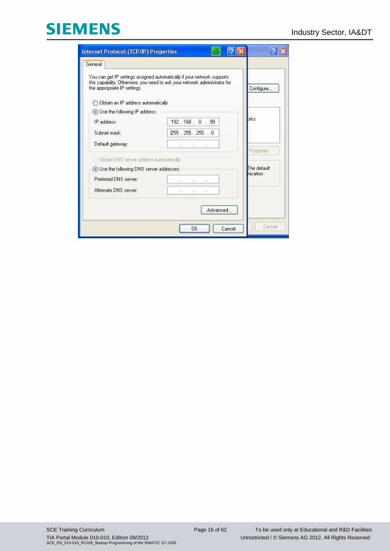
2. Select the 'Properties’ from the 'Internet Protocol (TCP/IP)’ ( Internet Protocol (TCP/IP)
Properties)
3. You can now set the ’IP address’ and the ’Subnet screen form’, and accept with ’OK’ ( Use
the following IP address IP address: 192.168.0.99 Subnet screen form 255.255.255.0
OK Close)
Industry Sector, IA&DT
SCE Training Curriculum Page 16 of 62 To be used only at Educational and R&D Facilities
TIA Portal Module 010-010, Edition 09/2012 Unrestricted / © Siemens AG 2012. All Rights Reserved SCE_EN_010-010_R1209_Startup Programming of the SIMATIC S7-1200
Industry Sector, IA&DT
SCE Training Curriculum Page 17 of 62 To be used only at Educational and R&D Facilities
TIA Portal Module 010-010, Edition 09/2012 Unrestricted / © Siemens AG 2012. All Rights Reserved SCE_EN_010-010_R1209_Startup Programming of the SIMATIC S7-1200
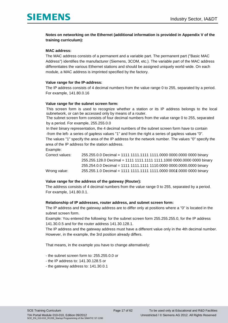
Notes on networking on the Ethernet (additional information is provided in Appendix V of the
training curriculum):
MAC address:
The MAC address consists of a permanent and a variable part. The permanent part ("Basic MAC
Address") identifies the manufacturer (Siemens, 3COM, etc.). The variable part of the MAC address
differentiates the various Ethernet stations and should be assigned uniquely world-wide. On each
module, a MAC address is imprinted specified by the factory.
Value range for the IP-address:
The IP address consists of 4 decimal numbers from the value range 0 to 255, separated by a period.
For example, 141.80.0.16
Value range for the subnet screen form:
This screen form is used to recognize whether a station or its IP address belongs to the local subnetwork, or can be accessed only by means of a router. The subnet screen form consists of four decimal numbers from the value range 0 to 255, separated
by a period. For example, 255.255.0.0
In their binary representation, the 4 decimal numbers of the subnet screen form have to contain
-from the left- a series of gapless values "1" and from the right a series of gapless values “0".
The values "1" specify the area of the IP address for the network number. The values "0" specify the
area of the IP address for the station address.
Example:
Correct values: 255.255.0.0 Decimal = 1111 1111.1111 1111.0000 0000.0000 0000 binary
255.255.128.0 Decimal = 1111 1111.1111 1111.1000 0000.0000 0000 binary
255.254.0.0 Decimal = 1111 1111.1111 1110.0000 0000.0000.0000 binary
Wrong value: 255.255.1.0 Decimal = 1111 1111.1111 1111.0000 0001.0000 0000 binary
Value range for the address of the gateway (Router):
The address consists of 4 decimal numbers from the value range 0 to 255, separated by a period.
For example, 141.80.0.1.
Relationship of IP addresses, router address, and subnet screen form:
The IP address and the gateway address are to differ only at positions where a "0" is located in the
subnet screen form.
Example: You entered the following: for the subnet screen form 255.255.255.0, for the IP address
141.30.0.5 and for the router address 141.30.128.1.
The IP address and the gateway address must have a different value only in the 4th decimal number.
However, in the example, the 3rd position already differs.
That means, in the example you have to change alternatively:
- the subnet screen form to: 255.255.0.0 or
- the IP address to: 141.30.128.5 or
- the gateway address to: 141.30.0.1
Industry Sector, IA&DT
SCE Training Curriculum Page 18 of 62 To be used only at Educational and R&D Facilities
TIA Portal Module 010-010, Edition 09/2012 Unrestricted / © Siemens AG 2012. All Rights Reserved SCE_EN_010-010_R1209_Startup Programming of the SIMATIC S7-1200
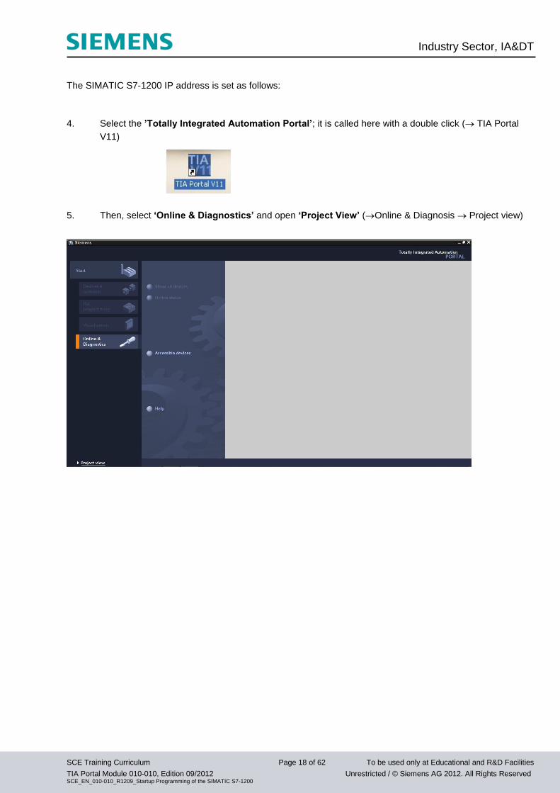
The SIMATIC S7-1200 IP address is set as follows:
4. Select the ’Totally Integrated Automation Portal’; it is called here with a double click ( TIA Portal
V11)
5. Then, select ‘Online & Diagnostics’ and open ‘Project View’ (Online & Diagnosis Project view)
Industry Sector, IA&DT
SCE Training Curriculum Page 19 of 62 To be used only at Educational and R&D Facilities
TIA Portal Module 010-010, Edition 09/2012 Unrestricted / © Siemens AG 2012. All Rights Reserved SCE_EN_010-010_R1209_Startup Programming of the SIMATIC S7-1200
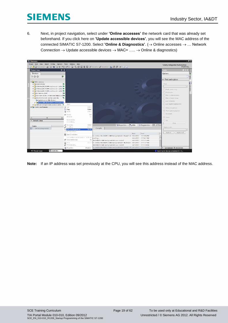
6. Next, in project navigation, select under ’Online accesses’ the network card that was already set
beforehand. If you click here on ’Update accessible devices’, you will see the MAC address of the
connected SIMATIC S7-1200. Select ’Online & Diagnostics’. ( Online accesses … Network
Connection Update accessible devices MAC= ….. Online & diagnostics)
Note: If an IP address was set previously at the CPU, you will see this address instead of the MAC address.
Industry Sector, IA&DT
SCE Training Curriculum Page 20 of 62 To be used only at Educational and R&D Facilities
TIA Portal Module 010-010, Edition 09/2012 Unrestricted / © Siemens AG 2012. All Rights Reserved SCE_EN_010-010_R1209_Startup Programming of the SIMATIC S7-1200
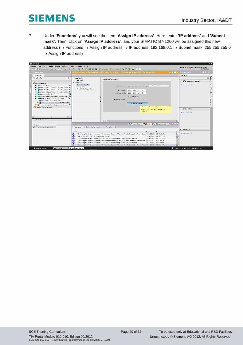
7. Under ’Functions’ you will see the item ’Assign IP address’. Here, enter ’IP address’ and ’Subnet
mask’. Then, click on ’Assign IP address’, and your SIMATIC S7-1200 will be assigned this new
address ( Functions Assign IP address IP address: 192.168.0.1 Subnet mask: 255.255.255.0
Assign IP address)
Industry Sector, IA&DT
SCE Training Curriculum Page 21 of 62 To be used only at Educational and R&D Facilities
TIA Portal Module 010-010, Edition 09/2012 Unrestricted / © Siemens AG 2012. All Rights Reserved SCE_EN_010-010_R1209_Startup Programming of the SIMATIC S7-1200
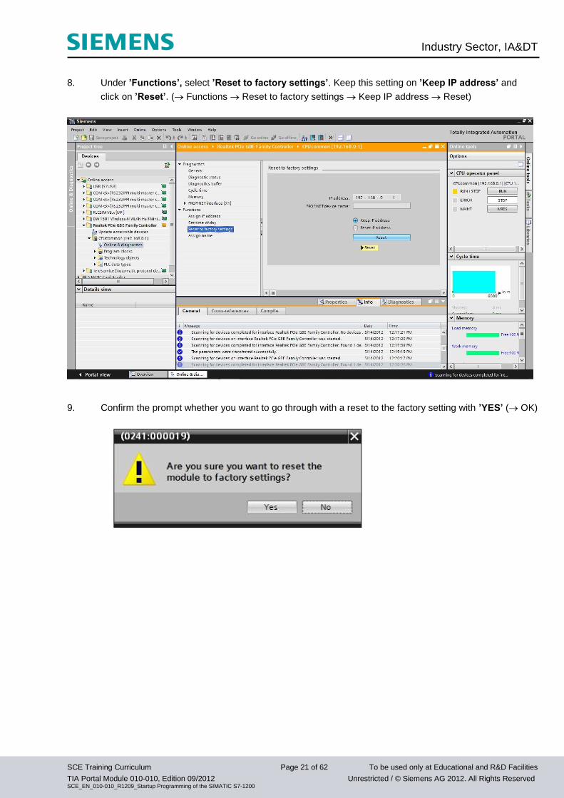
8. Under ’Functions’, select ’Reset to factory settings’. Keep this setting on ’Keep IP address’ and
click on ’Reset’. ( Functions Reset to factory settings Keep IP address Reset)
9. Confirm the prompt whether you want to go through with a reset to the factory setting with ’YES’ ( OK)
Industry Sector, IA&DT
SCE Training Curriculum Page 22 of 62 To be used only at Educational and R&D Facilities
TIA Portal Module 010-010, Edition 09/2012 Unrestricted / © Siemens AG 2012. All Rights Reserved SCE_EN_010-010_R1209_Startup Programming of the SIMATIC S7-1200
5. What is a PLC and what are PLCs Used For?
5.1 What does the term PLC mean?
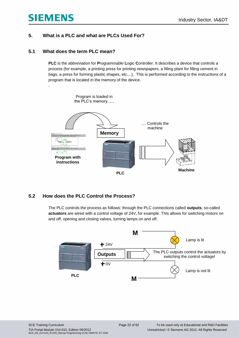
PLC is the abbreviation for Programmable Logic Controller. It describes a device that controls a
process (for example, a printing press for printing newspapers, a filling plant for filling cement in
bags, a press for forming plastic shapes, etc....). This is performed according to the instructions of a
program that is located in the memory of the device.
.
5.2 How does the PLC Control the Process?
The PLC controls the process as follows: through the PLC connections called outputs, so-called
actuators are wired with a control voltage of 24V, for example. This allows for switching motors on
and off, opening and closing valves, turning lamps on and off.
M
Program is loaded in the PLC’s memory......
PLC
Machine
Program with
instructions
Memory
.... Controls the machine
M
0V
24V
The PLC outputs control the actuators by switching the control voltage!
PLC
Outputs
Lamp is lit
Lamp is not lit
Industry Sector, IA&DT
SCE Training Curriculum Page 23 of 62 To be used only at Educational and R&D Facilities
TIA Portal Module 010-010, Edition 09/2012 Unrestricted / © Siemens AG 2012. All Rights Reserved SCE_EN_010-010_R1209_Startup Programming of the SIMATIC S7-1200
5.3 How does the PLC Get the Information about the Process States?
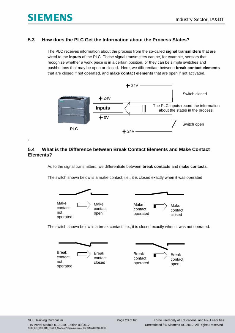
The PLC receives information about the process from the so-called signal transmitters that are
wired to the inputs of the PLC. These signal transmitters can be, for example, sensors that
recognize whether a work piece is in a certain position, or they can be simple switches and
pushbuttons that may be open or closed. Here, we differentiate between break contact elements
that are closed if not operated, and make contact elements that are open if not activated.
,
5.4 What is the Difference between Break Contact Elements and Make Contact Elements?
As to the signal transmitters, we differentiate between break contacts and make contacts.
The switch shown below is a make contact; i.e., it is closed exactly when it was operated
The switch shown below is a break contact; i.e., it is closed exactly when it was not operated.
Make contact not operated
Make contact open
Make contact operated
Make contact closed
Break contact not operated
Break contact closed
Break contact operated
Break contact open
24V
24V
0V
The PLC inputs record the information about the states in the process!
PLC
Inputs
Switch closed
Switch open
24V
Industry Sector, IA&DT
SCE Training Curriculum Page 24 of 62 To be used only at Educational and R&D Facilities
TIA Portal Module 010-010, Edition 09/2012 Unrestricted / © Siemens AG 2012. All Rights Reserved SCE_EN_010-010_R1209_Startup Programming of the SIMATIC S7-1200
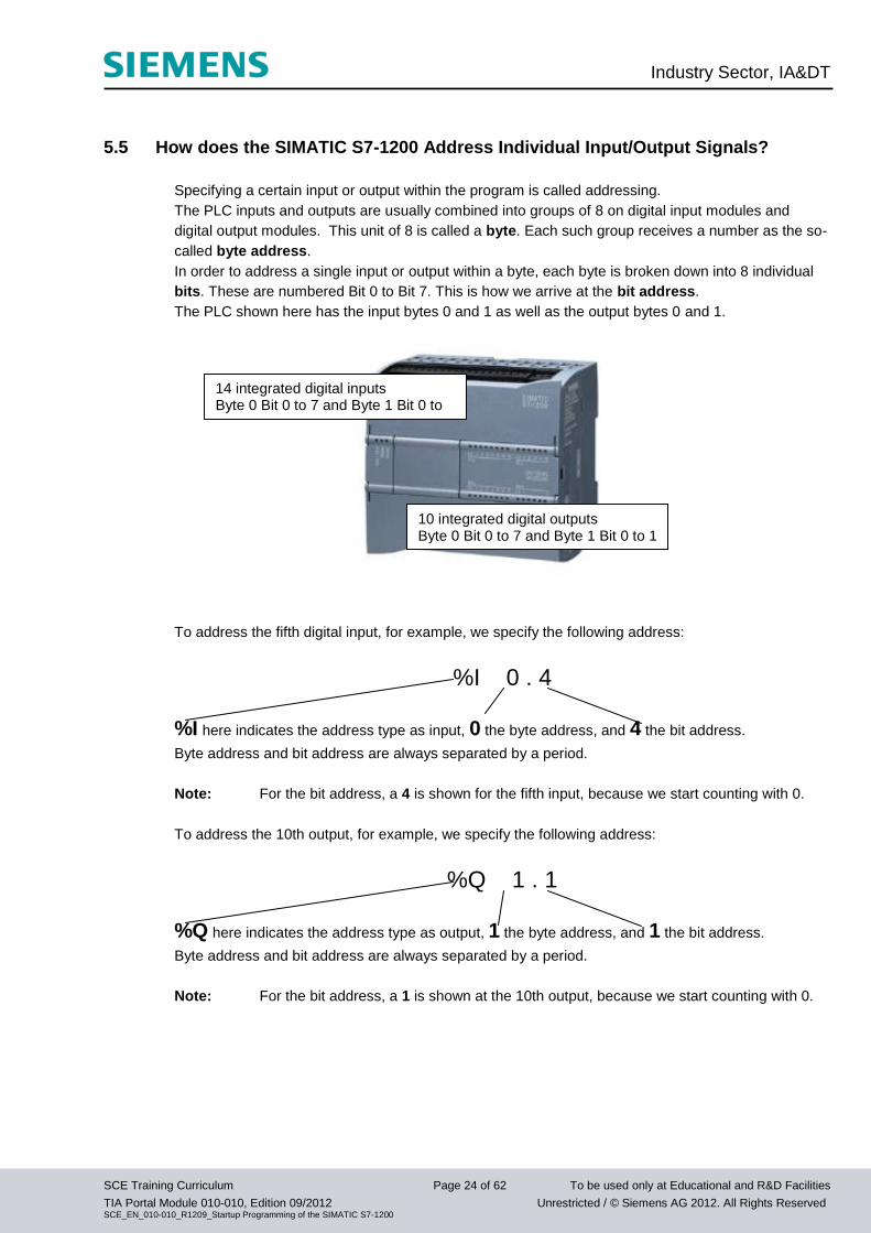
5.5 How does the SIMATIC S7-1200 Address Individual Input/Output Signals?
Specifying a certain input or output within the program is called addressing.
The PLC inputs and outputs are usually combined into groups of 8 on digital input modules and
digital output modules. This unit of 8 is called a byte. Each such group receives a number as the so-
called byte address.
In order to address a single input or output within a byte, each byte is broken down into 8 individual
bits. These are numbered Bit 0 to Bit 7. This is how we arrive at the bit address.
The PLC shown here has the input bytes 0 and 1 as well as the output bytes 0 and 1.
To address the fifth digital input, for example, we specify the following address:
%I 0 . 4
%I here indicates the address type as input, 0 the byte address, and 4 the bit address.
Byte address and bit address are always separated by a period.
Note: For the bit address, a 4 is shown for the fifth input, because we start counting with 0.
To address the 10th output, for example, we specify the following address:
%Q 1 . 1
%Q here indicates the address type as output, 1 the byte address, and 1 the bit address.
Byte address and bit address are always separated by a period.
Note: For the bit address, a 1 is shown at the 10th output, because we start counting with 0.
14 integrated digital inputs Byte 0 Bit 0 to 7 and Byte 1 Bit 0 to 5
10 integrated digital outputs Byte 0 Bit 0 to 7 and Byte 1 Bit 0 to 1
Industry Sector, IA&DT
SCE Training Curriculum Page 25 of 62 To be used only at Educational and R&D Facilities
TIA Portal Module 010-010, Edition 09/2012 Unrestricted / © Siemens AG 2012. All Rights Reserved SCE_EN_010-010_R1209_Startup Programming of the SIMATIC S7-1200
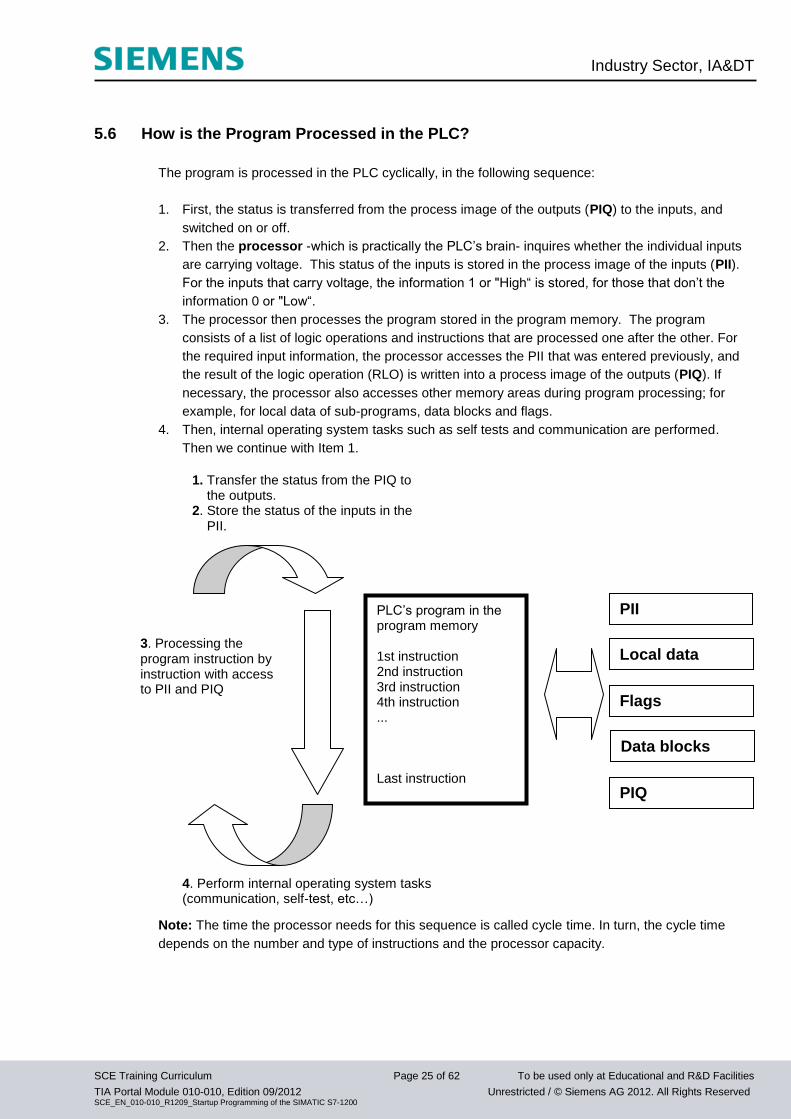
5.6 How is the Program Processed in the PLC?
The program is processed in the PLC cyclically, in the following sequence:
1. First, the status is transferred from the process image of the outputs (PIQ) to the inputs, and
switched on or off.
2. Then the processor -which is practically the PLC’s brain- inquires whether the individual inputs
are carrying voltage. This status of the inputs is stored in the process image of the inputs (PII).
For the inputs that carry voltage, the information 1 or "High“ is stored, for those that don’t the
information 0 or "Low“.
3. The processor then processes the program stored in the program memory. The program
consists of a list of logic operations and instructions that are processed one after the other. For
the required input information, the processor accesses the PII that was entered previously, and
the result of the logic operation (RLO) is written into a process image of the outputs (PIQ). If
necessary, the processor also accesses other memory areas during program processing; for
example, for local data of sub-programs, data blocks and flags.
4. Then, internal operating system tasks such as self tests and communication are performed.
Then we continue with Item 1.
Note: The time the processor needs for this sequence is called cycle time. In turn, the cycle time
depends on the number and type of instructions and the processor capacity.
PLC’s program in the program memory 1st instruction 2nd instruction 3rd instruction 4th instruction ... Last instruction
1. Transfer the status from the PIQ to the outputs. 2. Store the status of the inputs in the PII.
3. Processing the program instruction by instruction with access to PII and PIQ
4. Perform internal operating system tasks (communication, self-test, etc…)
PII
Local data
Flags
Data blocks
PIQ
Industry Sector, IA&DT
SCE Training Curriculum Page 26 of 62 To be used only at Educational and R&D Facilities
TIA Portal Module 010-010, Edition 09/2012 Unrestricted / © Siemens AG 2012. All Rights Reserved SCE_EN_010-010_R1209_Startup Programming of the SIMATIC S7-1200
5.7 What do Logic Operations Look Like in the PLC Program?
Logic operations are used to specify conditions for switching an output.
In the PLC program, these can be programmed in the programming languages Ladder Diagram
(LAD) or Function Block Diagram (FBD).
For illustrative purposes, we will use FBD here.
There are a large number of logic operations that can be used in PLC programs.
However, AND as well as OR operations and the NEGATION of an input are used most frequently
and are explained briefly below, using examples.
Note: Clearly arranged information about additional logic operations can be obtained quickly in
online help.
5.7.1 AND Operation
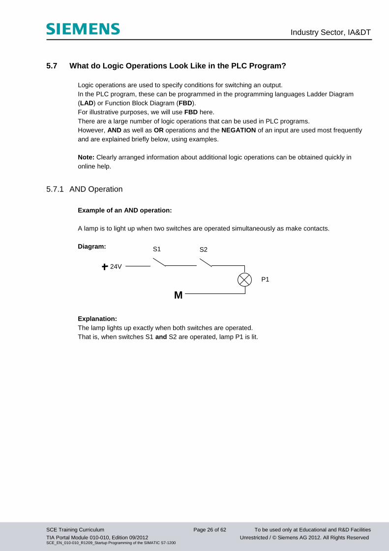
Example of an AND operation:
A lamp is to light up when two switches are operated simultaneously as make contacts.
Diagram:
Explanation:
The lamp lights up exactly when both switches are operated.
That is, when switches S1 and S2 are operated, lamp P1 is lit.
24V
M
S1 S2
P1
Industry Sector, IA&DT
SCE Training Curriculum Page 27 of 62 To be used only at Educational and R&D Facilities
TIA Portal Module 010-010, Edition 09/2012 Unrestricted / © Siemens AG 2012. All Rights Reserved SCE_EN_010-010_R1209_Startup Programming of the SIMATIC S7-1200
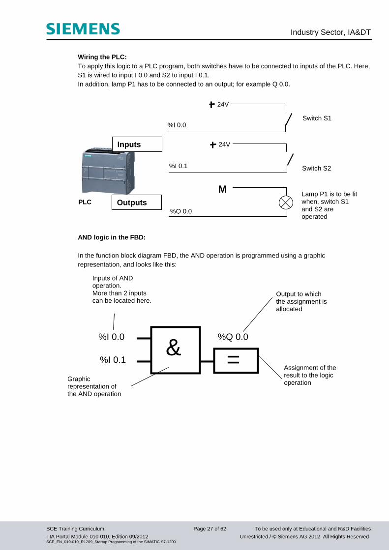
Wiring the PLC:
To apply this logic to a PLC program, both switches have to be connected to inputs of the PLC. Here,
S1 is wired to input I 0.0 and S2 to input I 0.1.
In addition, lamp P1 has to be connected to an output; for example Q 0.0.
AND logic in the FBD:
In the function block diagram FBD, the AND operation is programmed using a graphic
representation, and looks like this:
& =
%Q 0.0
%I 0.1
%I 0.0
Inputs of AND operation. More than 2 inputs can be located here.
Output to which the assignment is allocated
Graphic representation of the AND operation
Assignment of the result to the logic operation
M
24V
PLC
Inputs
Switch S1
Switch S2
%I 0.0
%Q 0.0
Outputs Lamp P1 is to be lit when, switch S1 and S2 are operated
24V
%I 0.1
Industry Sector, IA&DT
SCE Training Curriculum Page 28 of 62 To be used only at Educational and R&D Facilities
TIA Portal Module 010-010, Edition 09/2012 Unrestricted / © Siemens AG 2012. All Rights Reserved SCE_EN_010-010_R1209_Startup Programming of the SIMATIC S7-1200
5.7.2 OR Operation
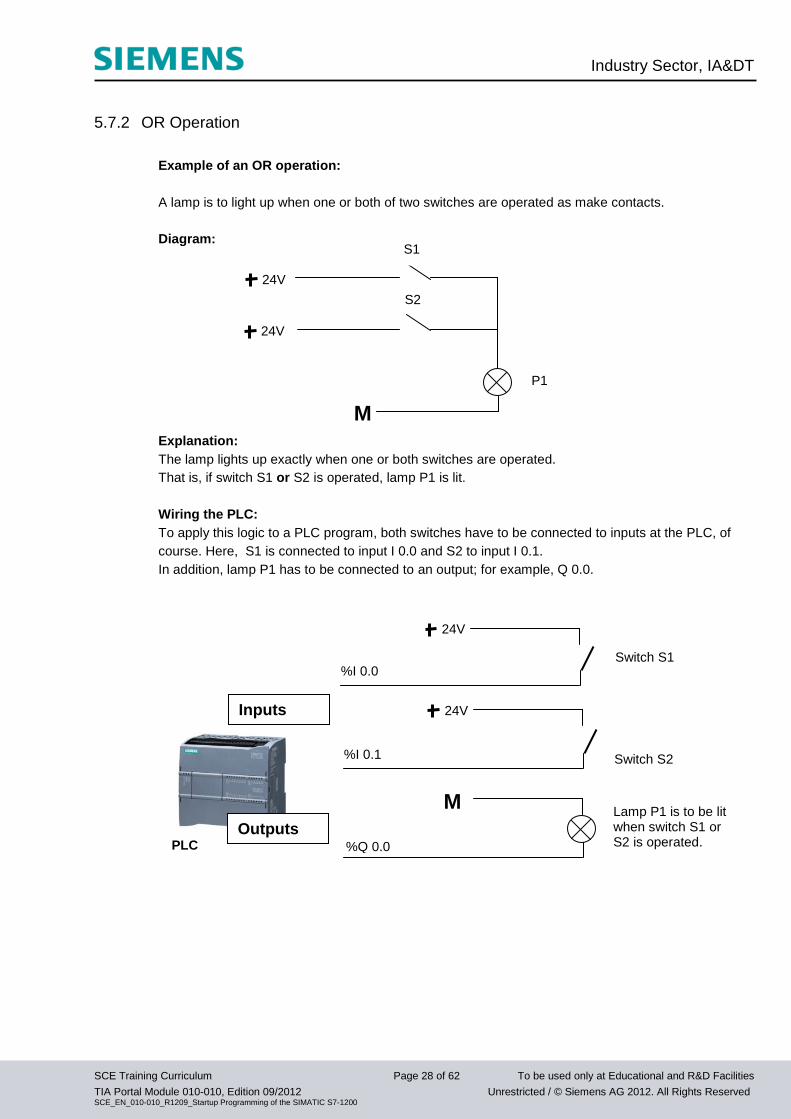
Example of an OR operation:
A lamp is to light up when one or both of two switches are operated as make contacts.
Diagram:
Explanation:
The lamp lights up exactly when one or both switches are operated.
That is, if switch S1 or S2 is operated, lamp P1 is lit.
Wiring the PLC:
To apply this logic to a PLC program, both switches have to be connected to inputs at the PLC, of
course. Here, S1 is connected to input I 0.0 and S2 to input I 0.1.
In addition, lamp P1 has to be connected to an output; for example, Q 0.0.
24V
M
S1
S2
P1
24V
M
24V
PLC
Inputs
Switch S1
Switch S2
%I 0.0
%Q 0.0
Outputs Lamp P1 is to be lit when switch S1 or S2 is operated.
24V
%I 0.1
Industry Sector, IA&DT
SCE Training Curriculum Page 29 of 62 To be used only at Educational and R&D Facilities
TIA Portal Module 010-010, Edition 09/2012 Unrestricted / © Siemens AG 2012. All Rights Reserved SCE_EN_010-010_R1209_Startup Programming of the SIMATIC S7-1200
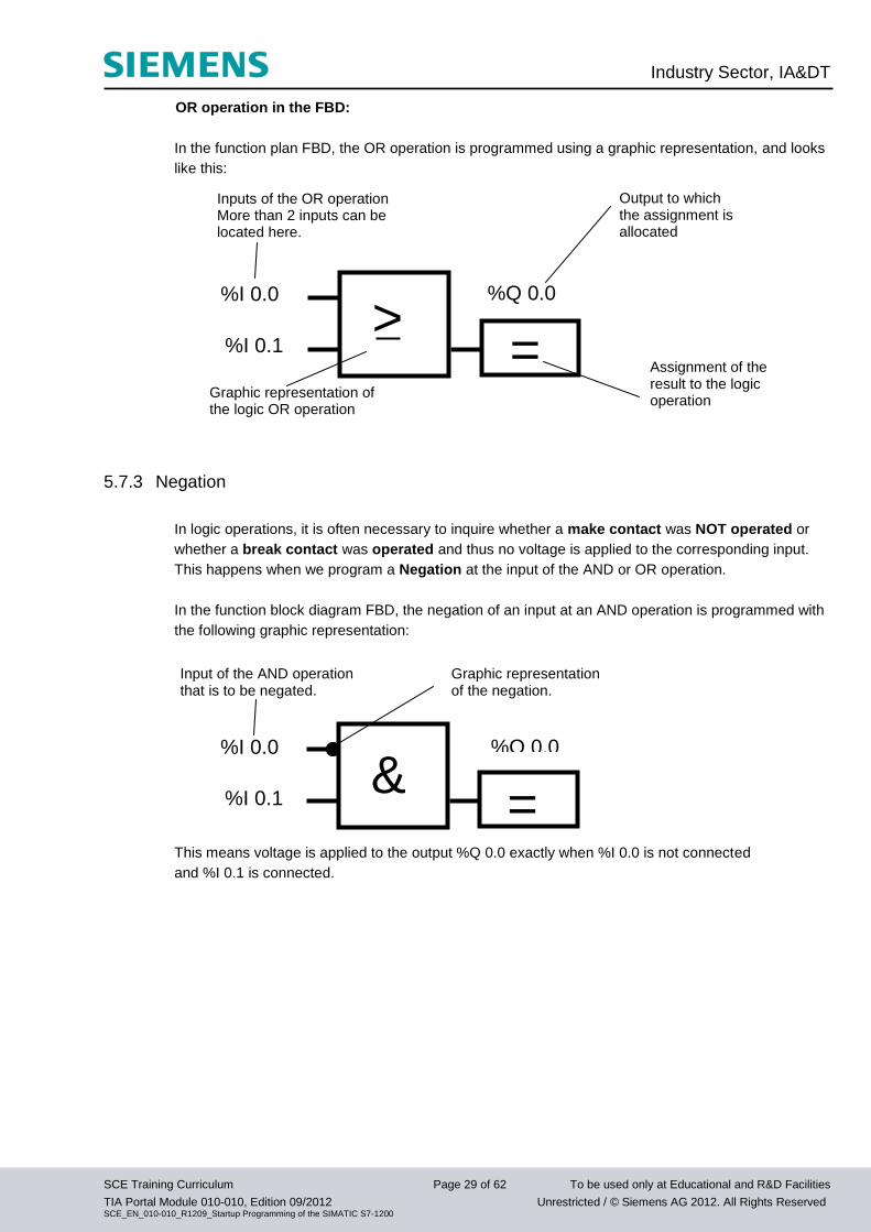
OR operation in the FBD:
In the function plan FBD, the OR operation is programmed using a graphic representation, and looks
like this:
5.7.3 Negation
In logic operations, it is often necessary to inquire whether a make contact was NOT operated or
whether a break contact was operated and thus no voltage is applied to the corresponding input.
This happens when we program a Negation at the input of the AND or OR operation.
In the function block diagram FBD, the negation of an input at an AND operation is programmed with
the following graphic representation:
This means voltage is applied to the output %Q 0.0 exactly when %I 0.0 is not connected
and %I 0.1 is connected.
=
%Q 0.0
Inputs of the OR operation More than 2 inputs can be located here.
%I 0.1
%I 0.0
Output to which the assignment is allocated
Graphic representation of the logic OR operation
Assignment of the result to the logic operation
>
&
Input of the AND operation that is to be negated.
Graphic representation of the negation.
=
%Q 0.0
%I 0.1
%I 0.0
Industry Sector, IA&DT
SCE Training Curriculum Page 30 of 62 To be used only at Educational and R&D Facilities
TIA Portal Module 010-010, Edition 09/2012 Unrestricted / © Siemens AG 2012. All Rights Reserved SCE_EN_010-010_R1209_Startup Programming of the SIMATIC S7-1200
5.8 How is the PLC Program generated? How does it get to the PLC’s memory?
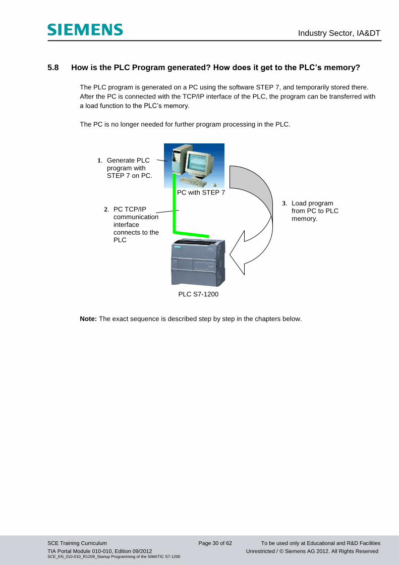
The PLC program is generated on a PC using the software STEP 7, and temporarily stored there.
After the PC is connected with the TCP/IP interface of the PLC, the program can be transferred with
a load function to the PLC’s memory.
The PC is no longer needed for further program processing in the PLC.
Note: The exact sequence is described step by step in the chapters below.
PC with STEP 7
PLC S7-1200
1. Generate PLC program with STEP 7 on PC.
2. PC TCP/IP communication interface connects to the PLC
3. Load program from PC to PLC memory.
Industry Sector, IA&DT
SCE Training Curriculum Page 31 of 62 To be used only at Educational and R&D Facilities
TIA Portal Module 010-010, Edition 09/2012 Unrestricted / © Siemens AG 2012. All Rights Reserved SCE_EN_010-010_R1209_Startup Programming of the SIMATIC S7-1200
6. Configuring and Operating the SIMATIC S7-1200
Module Spectrum:
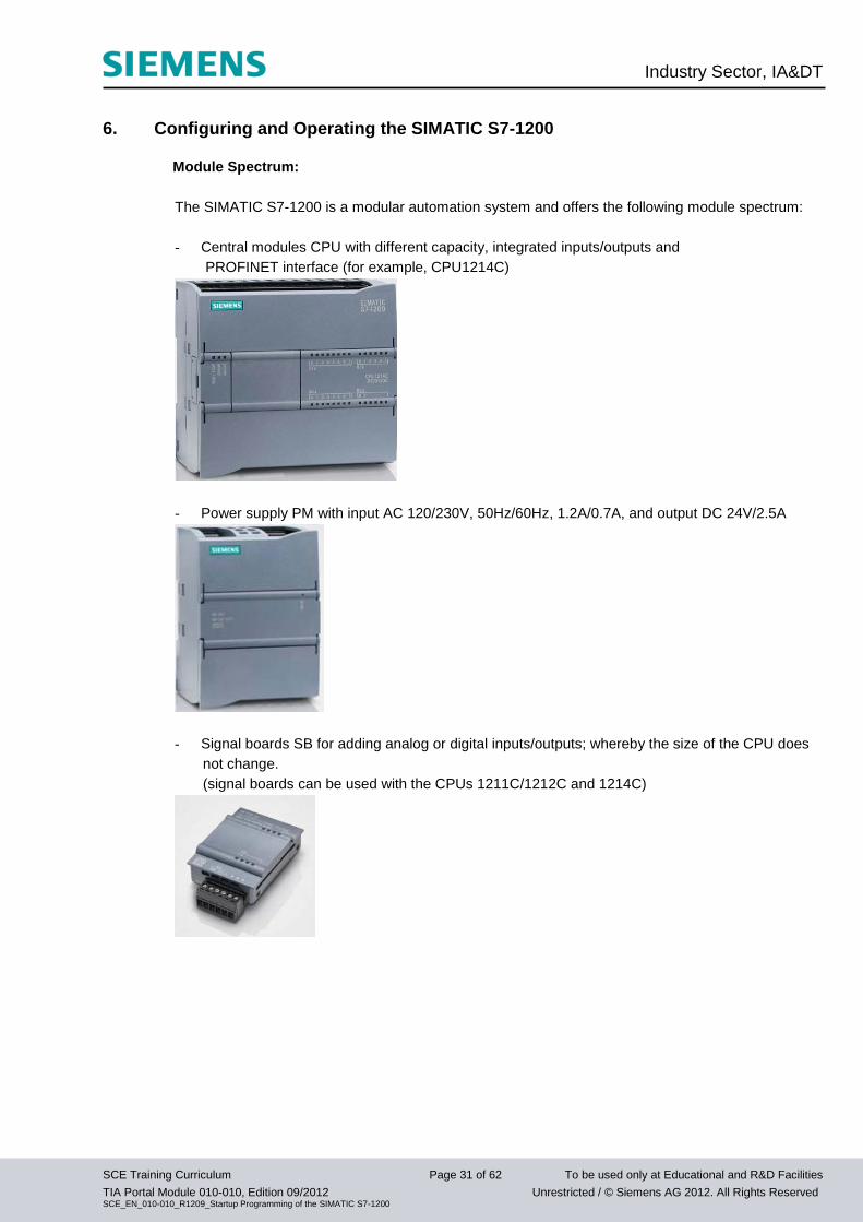
The SIMATIC S7-1200 is a modular automation system and offers the following module spectrum:
- Central modules CPU with different capacity, integrated inputs/outputs and
PROFINET interface (for example, CPU1214C)
- Power supply PM with input AC 120/230V, 50Hz/60Hz, 1.2A/0.7A, and output DC 24V/2.5A
- Signal boards SB for adding analog or digital inputs/outputs; whereby the size of the CPU does
not change.
(signal boards can be used with the CPUs 1211C/1212C and 1214C)
Industry Sector, IA&DT
SCE Training Curriculum Page 32 of 62 To be used only at Educational and R&D Facilities
TIA Portal Module 010-010, Edition 09/2012 Unrestricted / © Siemens AG 2012. All Rights Reserved SCE_EN_010-010_R1209_Startup Programming of the SIMATIC S7-1200
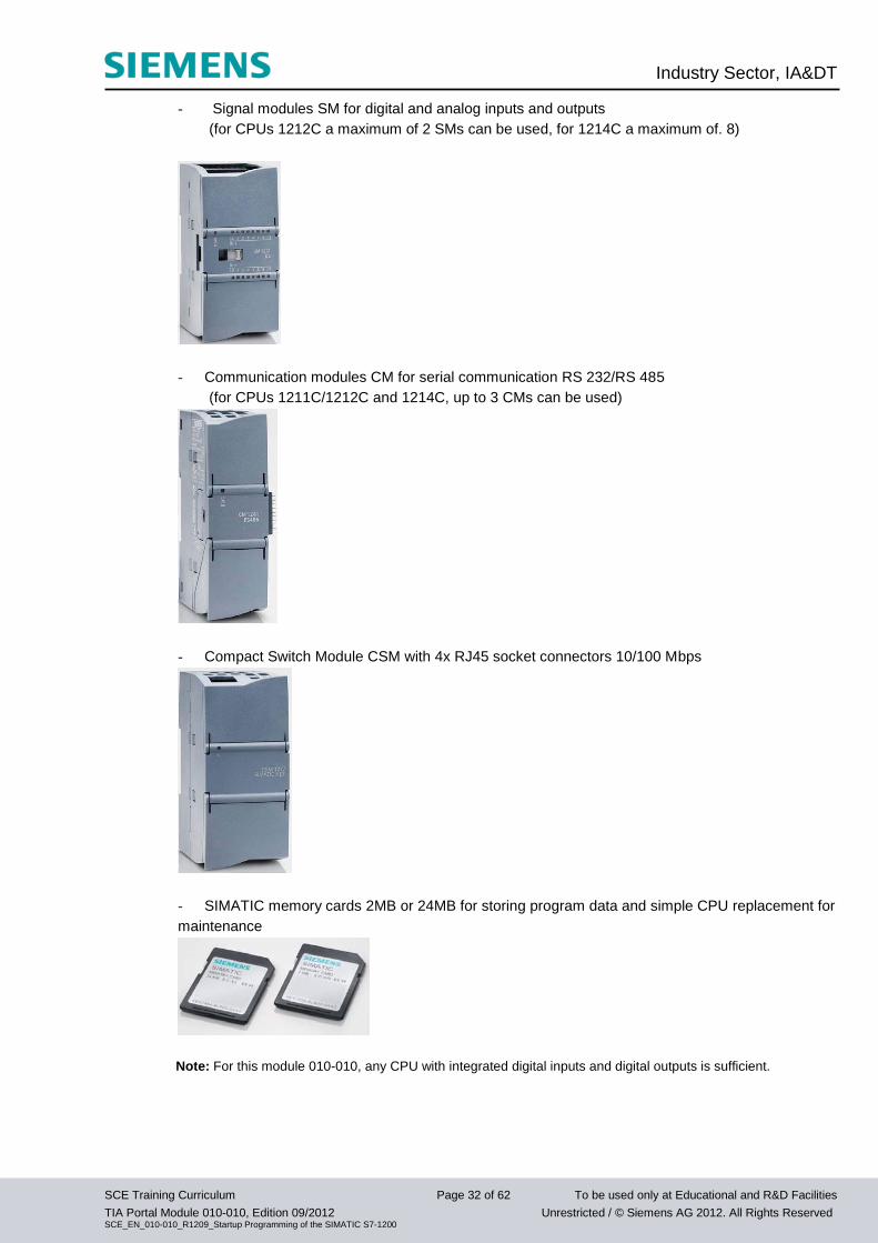
- Signal modules SM for digital and analog inputs and outputs
(for CPUs 1212C a maximum of 2 SMs can be used, for 1214C a maximum of. 8)
- Communication modules CM for serial communication RS 232/RS 485
(for CPUs 1211C/1212C and 1214C, up to 3 CMs can be used)
- Compact Switch Module CSM with 4x RJ45 socket connectors 10/100 Mbps
- SIMATIC memory cards 2MB or 24MB for storing program data and simple CPU replacement for
maintenance
Note: For this module 010-010, any CPU with integrated digital inputs and digital outputs is sufficient.
Industry Sector, IA&DT
SCE Training Curriculum Page 33 of 62 To be used only at Educational and R&D Facilities
TIA Portal Module 010-010, Edition 09/2012 Unrestricted / © Siemens AG 2012. All Rights Reserved SCE_EN_010-010_R1209_Startup Programming of the SIMATIC S7-1200
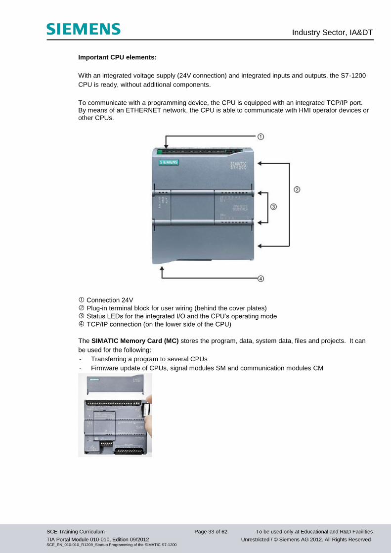
Important CPU elements:
With an integrated voltage supply (24V connection) and integrated inputs and outputs, the S7-1200
CPU is ready, without additional components.
To communicate with a programming device, the CPU is equipped with an integrated TCP/IP port. By means of an ETHERNET network, the CPU is able to communicate with HMI operator devices or other CPUs.
Connection 24V
Plug-in terminal block for user wiring (behind the cover plates)
Status LEDs for the integrated I/O and the CPU’s operating mode
TCP/IP connection (on the lower side of the CPU)
The SIMATIC Memory Card (MC) stores the program, data, system data, files and projects. It can
be used for the following:
- Transferring a program to several CPUs
- Firmware update of CPUs, signal modules SM and communication modules CM
Industry Sector, IA&DT
SCE Training Curriculum Page 34 of 62 To be used only at Educational and R&D Facilities
TIA Portal Module 010-010, Edition 09/2012 Unrestricted / © Siemens AG 2012. All Rights Reserved SCE_EN_010-010_R1209_Startup Programming of the SIMATIC S7-1200
Operating Modes of the CPU
The CPU has the following operating modes:
● In the operating mode STOP, the CPU does not execute the program, and you can load a project
● In the operating mode STARTUP, the CPU performs a startup.
● In the operating mode RUN, the program is executed cyclically. Projects cannot be loaded in the
CPU’s RUN mode.
The CPU does not have a physical switch for changing the operating mode. The operating mode
(STOP or RUN) is changed by using the button on the operator panel of the software STEP7 Basic.
In addition, the operator panel is provided with the button MRES to perform a general memory reset
and displays the status LEDs of the CPU.
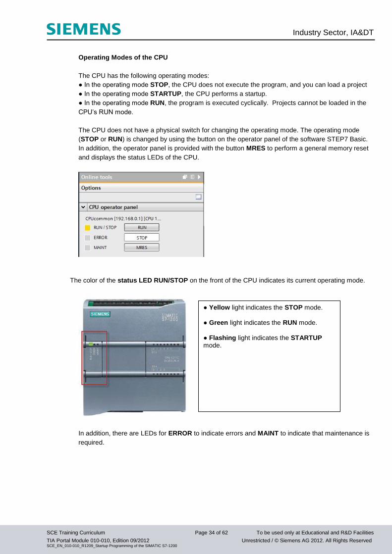
The color of the status LED RUN/STOP on the front of the CPU indicates its current operating mode.
In addition, there are LEDs for ERROR to indicate errors and MAINT to indicate that maintenance is
required.
● Yellow light indicates the STOP mode. ● Green light indicates the RUN mode. ● Flashing light indicates the STARTUP mode.
Industry Sector, IA&DT
SCE Training Curriculum Page 35 of 62 To be used only at Educational and R&D Facilities
TIA Portal Module 010-010, Edition 09/2012 Unrestricted / © Siemens AG 2012. All Rights Reserved SCE_EN_010-010_R1209_Startup Programming of the SIMATIC S7-1200
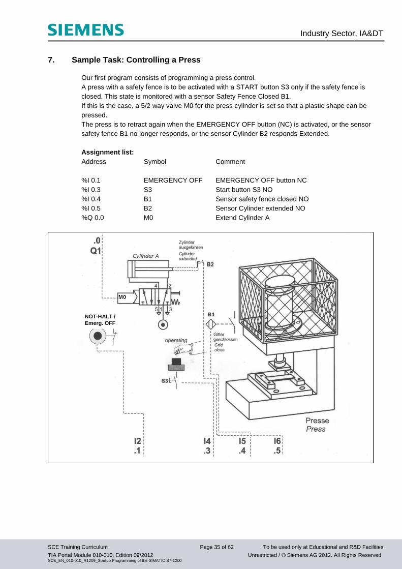
7. Sample Task: Controlling a Press
Our first program consists of programming a press control.
A press with a safety fence is to be activated with a START button S3 only if the safety fence is
closed. This state is monitored with a sensor Safety Fence Closed B1.
If this is the case, a 5/2 way valve M0 for the press cylinder is set so that a plastic shape can be
pressed.
The press is to retract again when the EMERGENCY OFF button (NC) is activated, or the sensor
safety fence B1 no longer responds, or the sensor Cylinder B2 responds Extended.
Assignment list:
Address Symbol Comment
%I 0.1 EMERGENCY OFF EMERGENCY OFF button NC
%I 0.3 S3 Start button S3 NO
%I 0.4 B1 Sensor safety fence closed NO
%I 0.5 B2 Sensor Cylinder extended NO
%Q 0.0 M0 Extend Cylinder A
NOT-HALT /
Emerg. OFF
Industry Sector, IA&DT
SCE Training Curriculum Page 36 of 62 To be used only at Educational and R&D Facilities
TIA Portal Module 010-010, Edition 09/2012 Unrestricted / © Siemens AG 2012. All Rights Reserved SCE_EN_010-010_R1209_Startup Programming of the SIMATIC S7-1200
8. Programming the Press for the SIMATIC S7-1200
The software 'Totally Integrated Automation Portal’ manages the project and does the
programming.
Here, under a uniform interface, the components such as the controller, visualization and networking
the automation solution are set up, parameterized and programmed.
Online tools are provided for error diagnosis.
The software 'Totally Integrated Automation Portal’ has two different views: the portal view and
the project view.
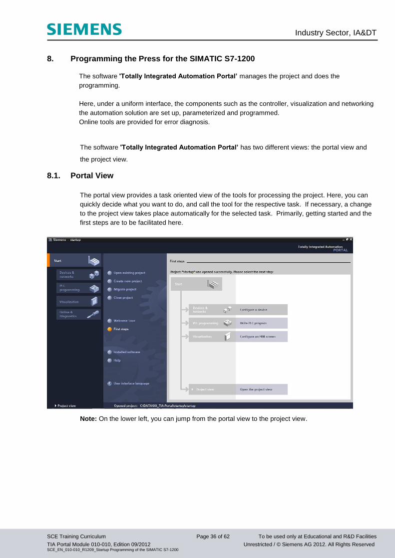
8.1. Portal View
The portal view provides a task oriented view of the tools for processing the project. Here, you can
quickly decide what you want to do, and call the tool for the respective task. If necessary, a change
to the project view takes place automatically for the selected task. Primarily, getting started and the
first steps are to be facilitated here.
Note: On the lower left, you can jump from the portal view to the project view.
Industry Sector, IA&DT
SCE Training Curriculum Page 37 of 62 To be used only at Educational and R&D Facilities
TIA Portal Module 010-010, Edition 09/2012 Unrestricted / © Siemens AG 2012. All Rights Reserved SCE_EN_010-010_R1209_Startup Programming of the SIMATIC S7-1200
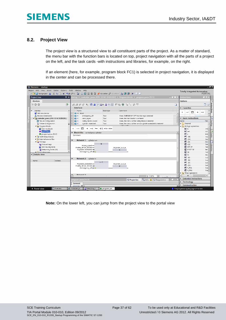
8.2. Project View
The project view is a structured view to all constituent parts of the project. As a matter of standard,
the menu bar with the function bars is located on top, project navigation with all the parts of a project
on the left, and the task cards -with instructions and libraries, for example, on the right.
If an element (here, for example, program block FC1) is selected in project navigation, it is displayed
in the center and can be processed there.
Note: On the lower left, you can jump from the project view to the portal view
Industry Sector, IA&DT
SCE Training Curriculum Page 38 of 62 To be used only at Educational and R&D Facilities
TIA Portal Module 010-010, Edition 09/2012 Unrestricted / © Siemens AG 2012. All Rights Reserved SCE_EN_010-010_R1209_Startup Programming of the SIMATIC S7-1200
With the following steps, we are setting up a project for the SIMATIC S7-1200 and we are programming the
solution of the task:
1. The central tool is the 'Totally Integrated Automation Portal’ which is called here with a double click.
( Totally Integrated Automation Portal V11)
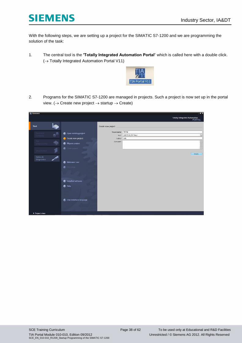
2. Programs for the SIMATIC S7-1200 are managed in projects. Such a project is now set up in the portal
view. ( Create new project startup Create)
Industry Sector, IA&DT
SCE Training Curriculum Page 39 of 62 To be used only at Educational and R&D Facilities
TIA Portal Module 010-010, Edition 09/2012 Unrestricted / © Siemens AG 2012. All Rights Reserved SCE_EN_010-010_R1209_Startup Programming of the SIMATIC S7-1200
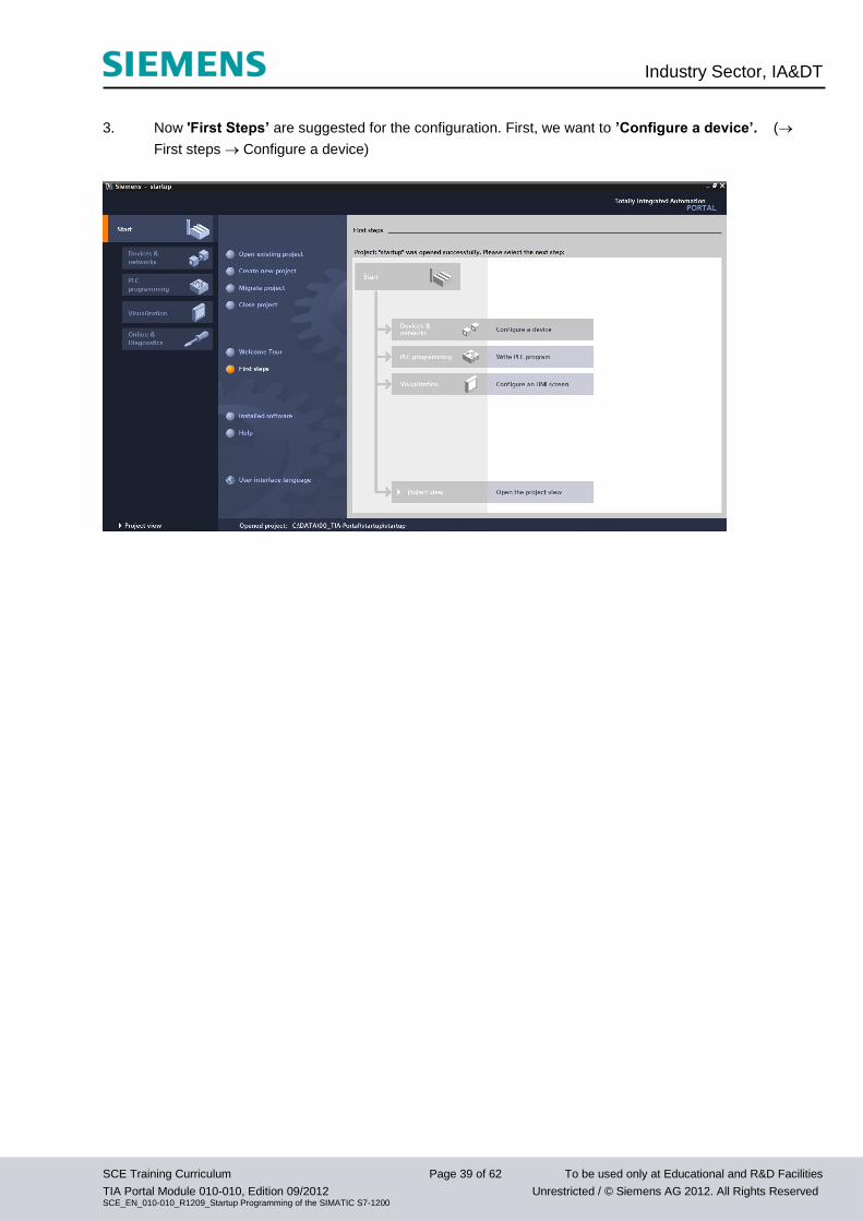
3. Now 'First Steps’ are suggested for the configuration. First, we want to ’Configure a device’. (
First steps Configure a device)
Industry Sector, IA&DT
SCE Training Curriculum Page 40 of 62 To be used only at Educational and R&D Facilities
TIA Portal Module 010-010, Edition 09/2012 Unrestricted / © Siemens AG 2012. All Rights Reserved SCE_EN_010-010_R1209_Startup Programming of the SIMATIC S7-1200
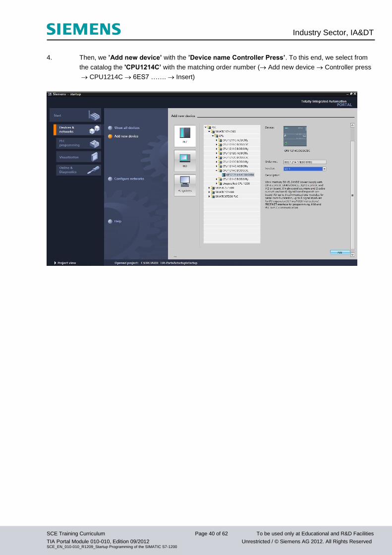
4. Then, we ’Add new device’ with the ’Device name Controller Press’. To this end, we select from
the catalog the 'CPU1214C’ with the matching order number ( Add new device Controller press
CPU1214C 6ES7 ……. Insert)
Industry Sector, IA&DT
SCE Training Curriculum Page 41 of 62 To be used only at Educational and R&D Facilities
TIA Portal Module 010-010, Edition 09/2012 Unrestricted / © Siemens AG 2012. All Rights Reserved SCE_EN_010-010_R1209_Startup Programming of the SIMATIC S7-1200
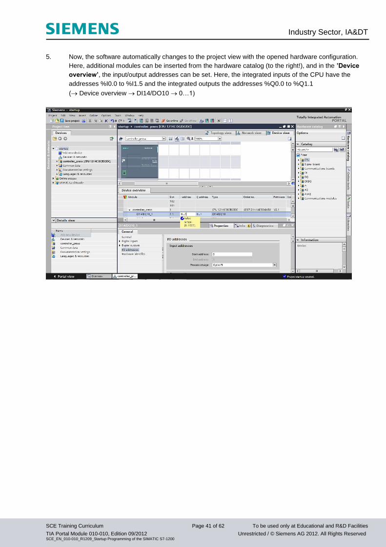
5. Now, the software automatically changes to the project view with the opened hardware configuration.
Here, additional modules can be inserted from the hardware catalog (to the right!), and in the ’Device
overview’, the input/output addresses can be set. Here, the integrated inputs of the CPU have the
addresses %I0.0 to %I1.5 and the integrated outputs the addresses %Q0.0 to %Q1.1
( Device overview DI14/DO10 0…1)
Industry Sector, IA&DT
SCE Training Curriculum Page 42 of 62 To be used only at Educational and R&D Facilities
TIA Portal Module 010-010, Edition 09/2012 Unrestricted / © Siemens AG 2012. All Rights Reserved SCE_EN_010-010_R1209_Startup Programming of the SIMATIC S7-1200
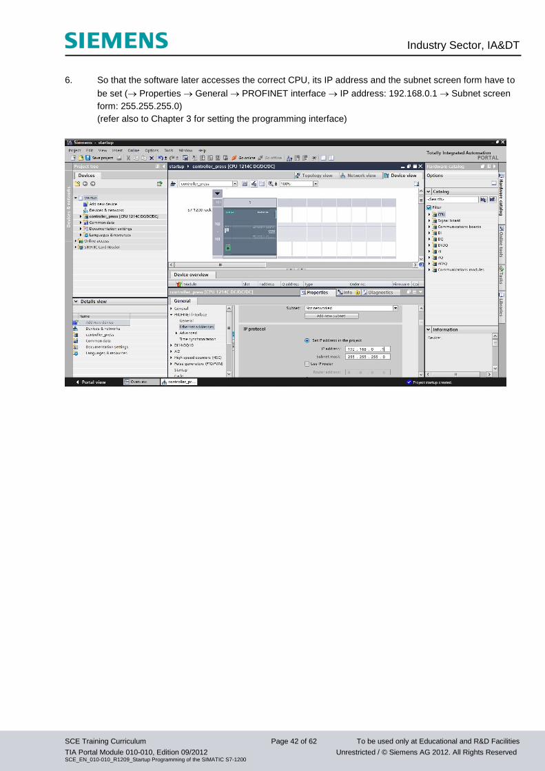
6. So that the software later accesses the correct CPU, its IP address and the subnet screen form have to
be set ( Properties General PROFINET interface IP address: 192.168.0.1 Subnet screen
form: 255.255.255.0)
(refer also to Chapter 3 for setting the programming interface)
Industry Sector, IA&DT
SCE Training Curriculum Page 43 of 62 To be used only at Educational and R&D Facilities
TIA Portal Module 010-010, Edition 09/2012 Unrestricted / © Siemens AG 2012. All Rights Reserved SCE_EN_010-010_R1209_Startup Programming of the SIMATIC S7-1200
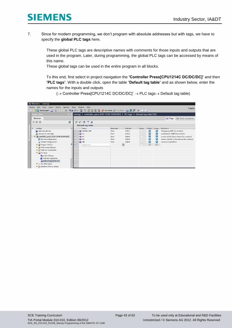
7. Since for modern programming, we don’t program with absolute addresses but with tags, we have to
specify the global PLC tags here.
These global PLC tags are descriptive names with comments for those inputs and outputs that are
used in the program. Later, during programming, the global PLC tags can be accessed by means of
this name.
These global tags can be used in the entire program in all blocks.
To this end, first select in project navigation the 'Controller Press[CPU1214C DC/DC/DC]’ and then
’PLC tags’. With a double click, open the table ’Default tag table’ and as shown below, enter the
names for the inputs and outputs
( Controller Press[CPU1214C DC/DC/DC]’ PLC tags Default tag table)
Industry Sector, IA&DT
SCE Training Curriculum Page 44 of 62 To be used only at Educational and R&D Facilities
TIA Portal Module 010-010, Edition 09/2012 Unrestricted / © Siemens AG 2012. All Rights Reserved SCE_EN_010-010_R1209_Startup Programming of the SIMATIC S7-1200
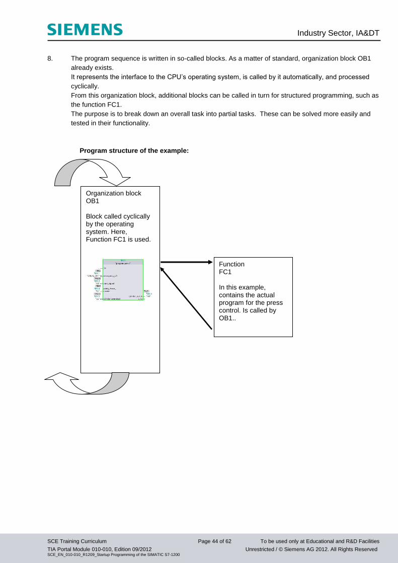
8. The program sequence is written in so-called blocks. As a matter of standard, organization block OB1
already exists.
It represents the interface to the CPU’s operating system, is called by it automatically, and processed
cyclically.
From this organization block, additional blocks can be called in turn for structured programming, such as
the function FC1.
The purpose is to break down an overall task into partial tasks. These can be solved more easily and
tested in their functionality.
Program structure of the example:
Organization block OB1 Block called cyclically by the operating system. Here, Function FC1 is used.
Function FC1 In this example, contains the actual program for the press control. Is called by OB1..
Industry Sector, IA&DT
SCE Training Curriculum Page 45 of 62 To be used only at Educational and R&D Facilities
TIA Portal Module 010-010, Edition 09/2012 Unrestricted / © Siemens AG 2012. All Rights Reserved SCE_EN_010-010_R1209_Startup Programming of the SIMATIC S7-1200
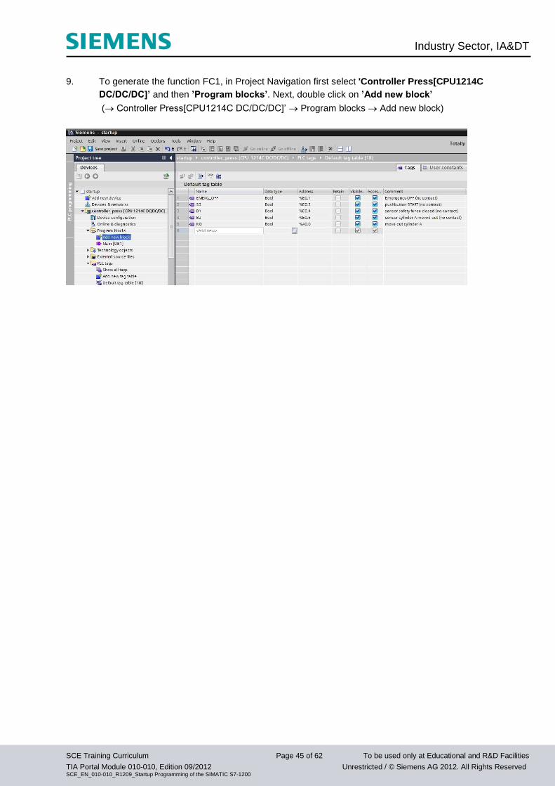
9. To generate the function FC1, in Project Navigation first select 'Controller Press[CPU1214C
DC/DC/DC]’ and then ’Program blocks’. Next, double click on ’Add new block’
( Controller Press[CPU1214C DC/DC/DC]’ Program blocks Add new block)
Industry Sector, IA&DT
SCE Training Curriculum Page 46 of 62 To be used only at Educational and R&D Facilities
TIA Portal Module 010-010, Edition 09/2012 Unrestricted / © Siemens AG 2012. All Rights Reserved SCE_EN_010-010_R1209_Startup Programming of the SIMATIC S7-1200
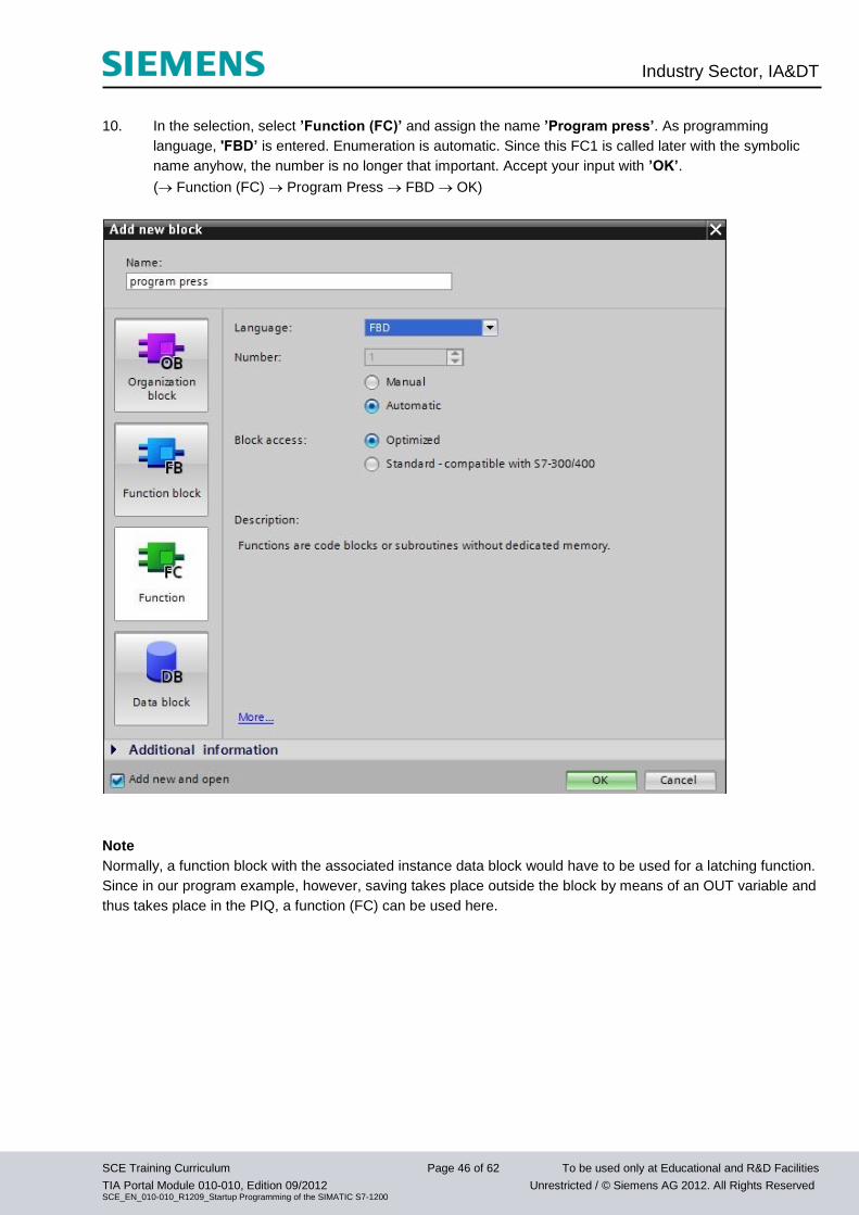
10. In the selection, select ’Function (FC)’ and assign the name ’Program press’. As programming
language, 'FBD’ is entered. Enumeration is automatic. Since this FC1 is called later with the symbolic
name anyhow, the number is no longer that important. Accept your input with ’OK’.
( Function (FC) Program Press FBD OK)
Note
Normally, a function block with the associated instance data block would have to be used for a latching function.
Since in our program example, however, saving takes place outside the block by means of an OUT variable and
thus takes place in the PIQ, a function (FC) can be used here.
Industry Sector, IA&DT
SCE Training Curriculum Page 47 of 62 To be used only at Educational and R&D Facilities
TIA Portal Module 010-010, Edition 09/2012 Unrestricted / © Siemens AG 2012. All Rights Reserved SCE_EN_010-010_R1209_Startup Programming of the SIMATIC S7-1200
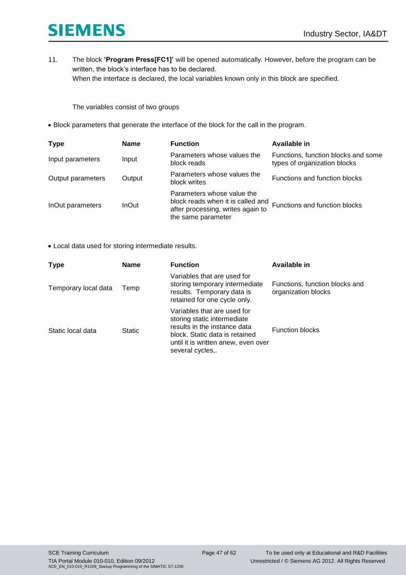
11. The block ’Program Press[FC1]’ will be opened automatically. However, before the program can be
written, the block’s interface has to be declared.
When the interface is declared, the local variables known only in this block are specified.
The variables consist of two groups
Block parameters that generate the interface of the block for the call in the program.
Type Name Function Available in
Input parameters Input Parameters whose values the block reads
Functions, function blocks and some types of organization blocks
Output parameters Output Parameters whose values the block writes
Functions and function blocks
InOut parameters InOut
Parameters whose value the block reads when it is called and after processing, writes again to the same parameter
Functions and function blocks
Local data used for storing intermediate results.
Type Name Function Available in
Temporary local data Temp
Variables that are used for storing temporary intermediate results. Temporary data is retained for one cycle only.
Functions, function blocks and organization blocks
Static local data Static
Variables that are used for storing static intermediate results in the instance data block. Static data is retained until it is written anew, even over several cycles,.
Function blocks
Industry Sector, IA&DT
SCE Training Curriculum Page 48 of 62 To be used only at Educational and R&D Facilities
TIA Portal Module 010-010, Edition 09/2012 Unrestricted / © Siemens AG 2012. All Rights Reserved SCE_EN_010-010_R1209_Startup Programming of the SIMATIC S7-1200
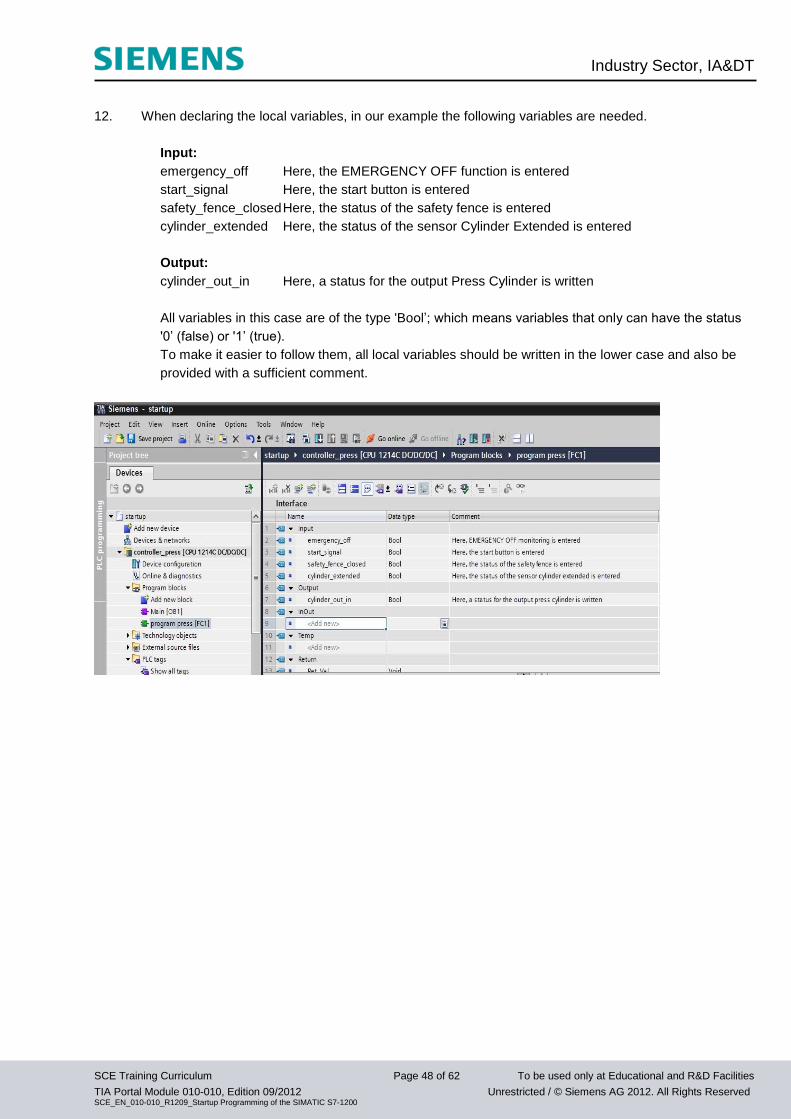
12. When declaring the local variables, in our example the following variables are needed.
Input:
emergency_off Here, the EMERGENCY OFF function is entered
start_signal Here, the start button is entered
safety_fence_closed Here, the status of the safety fence is entered
cylinder_extended Here, the status of the sensor Cylinder Extended is entered
Output:
cylinder_out_in Here, a status for the output Press Cylinder is written
All variables in this case are of the type 'Bool’; which means variables that only can have the status
'0’ (false) or '1’ (true).
To make it easier to follow them, all local variables should be written in the lower case and also be
provided with a sufficient comment.
Industry Sector, IA&DT
SCE Training Curriculum Page 49 of 62 To be used only at Educational and R&D Facilities
TIA Portal Module 010-010, Edition 09/2012 Unrestricted / © Siemens AG 2012. All Rights Reserved SCE_EN_010-010_R1209_Startup Programming of the SIMATIC S7-1200
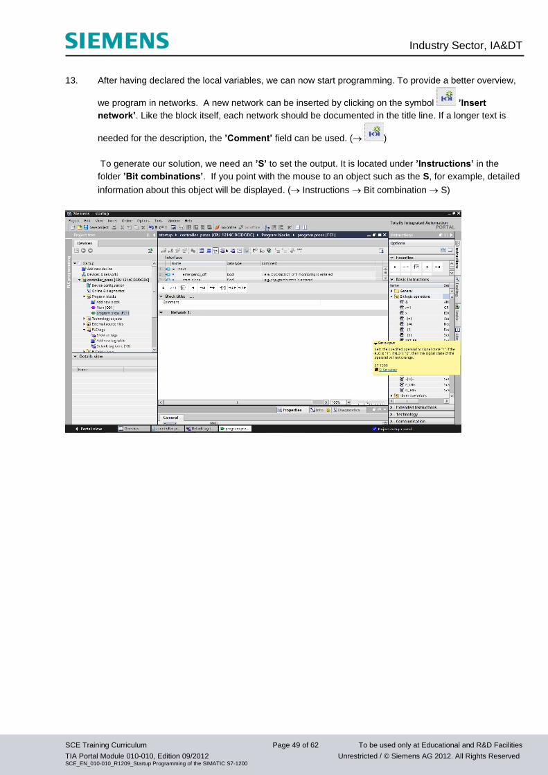
13. After having declared the local variables, we can now start programming. To provide a better overview,
we program in networks. A new network can be inserted by clicking on the symbol ’Insert
network’. Like the block itself, each network should be documented in the title line. If a longer text is
needed for the description, the ’Comment’ field can be used. ( )
To generate our solution, we need an ’S’ to set the output. It is located under ’Instructions’ in the
folder ’Bit combinations’. If you point with the mouse to an object such as the S, for example, detailed
information about this object will be displayed. ( Instructions Bit combination S)
Industry Sector, IA&DT
SCE Training Curriculum Page 50 of 62 To be used only at Educational and R&D Facilities
TIA Portal Module 010-010, Edition 09/2012 Unrestricted / © Siemens AG 2012. All Rights Reserved SCE_EN_010-010_R1209_Startup Programming of the SIMATIC S7-1200
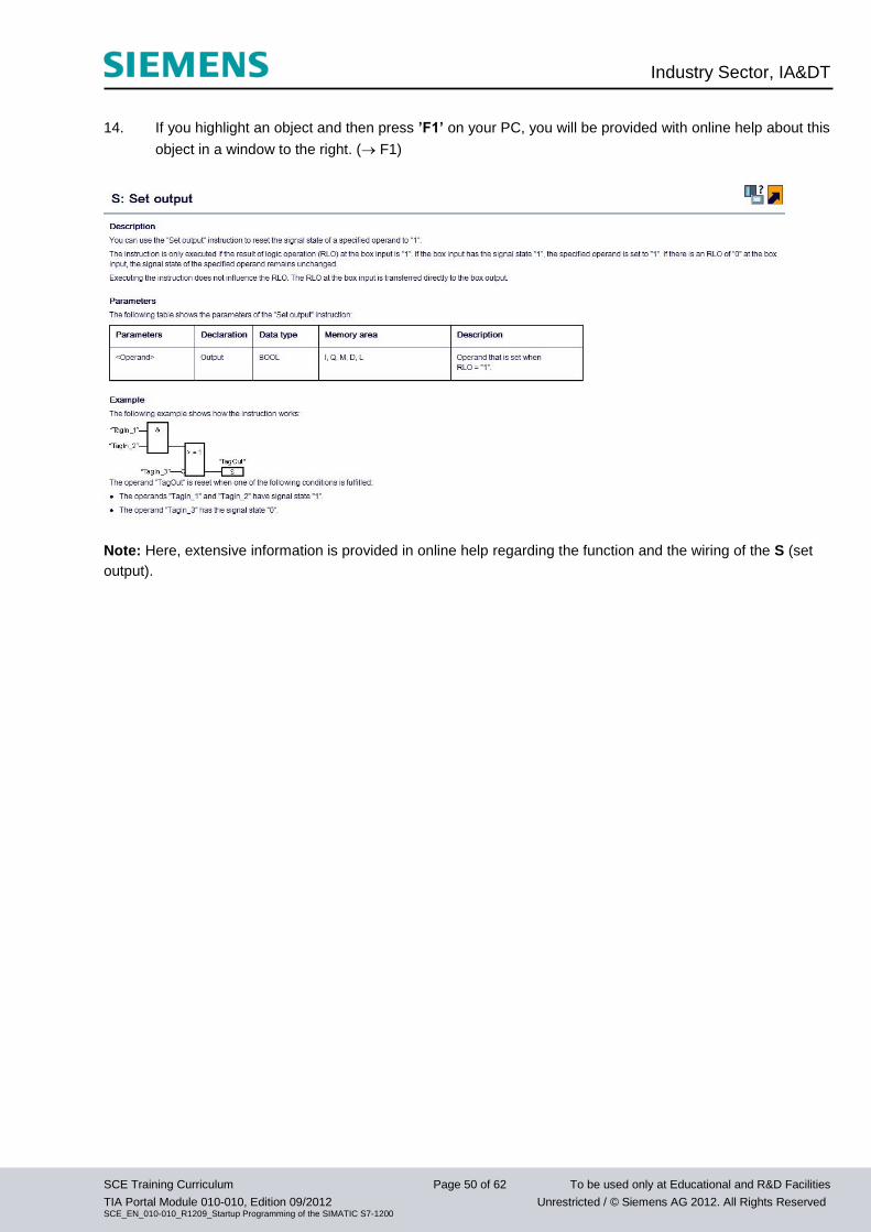
14. If you highlight an object and then press ’F1’ on your PC, you will be provided with online help about this
object in a window to the right. ( F1)
Note: Here, extensive information is provided in online help regarding the function and the wiring of the S (set
output).
Industry Sector, IA&DT
SCE Training Curriculum Page 51 of 62 To be used only at Educational and R&D Facilities
TIA Portal Module 010-010, Edition 09/2012 Unrestricted / © Siemens AG 2012. All Rights Reserved SCE_EN_010-010_R1209_Startup Programming of the SIMATIC S7-1200
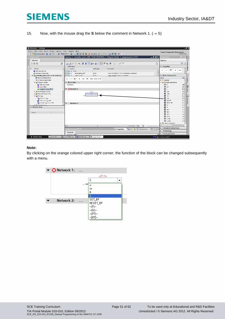
15. Now, with the mouse drag the S below the comment in Network 1. ( S)
Note:
By clicking on the orange colored upper right corner, the function of the block can be changed subsequently
with a menu.
Industry Sector, IA&DT
SCE Training Curriculum Page 52 of 62 To be used only at Educational and R&D Facilities
TIA Portal Module 010-010, Edition 09/2012 Unrestricted / © Siemens AG 2012. All Rights Reserved SCE_EN_010-010_R1209_Startup Programming of the SIMATIC S7-1200
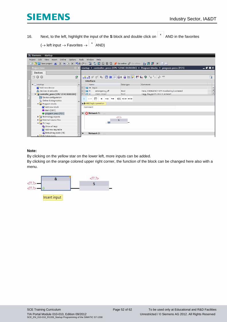
16. Next, to the left, highlight the input of the S block and double click on AND in the favorites
( left input Favorites AND)
Note:
By clicking on the yellow star on the lower left, more inputs can be added.
By clicking on the orange colored upper right corner, the function of the block can be changed here also with a
menu.
Industry Sector, IA&DT
SCE Training Curriculum Page 53 of 62 To be used only at Educational and R&D Facilities
TIA Portal Module 010-010, Edition 09/2012 Unrestricted / © Siemens AG 2012. All Rights Reserved SCE_EN_010-010_R1209_Startup Programming of the SIMATIC S7-1200
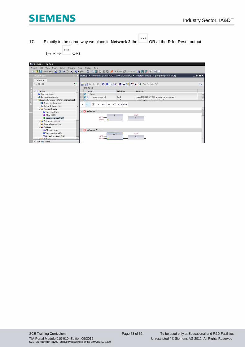
17. Exactly in the same way we place in Network 2 the OR at the R for Reset output
( R OR)
Industry Sector, IA&DT
SCE Training Curriculum Page 54 of 62 To be used only at Educational and R&D Facilities
TIA Portal Module 010-010, Edition 09/2012 Unrestricted / © Siemens AG 2012. All Rights Reserved SCE_EN_010-010_R1209_Startup Programming of the SIMATIC S7-1200
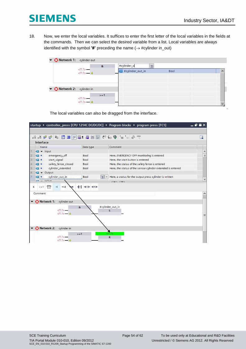
18. Now, we enter the local variables. It suffices to enter the first letter of the local variables in the fields at
the commands. Then we can select the desired variable from a list. Local variables are always
identified with the symbol '#’ preceding the name ( #cylinder in_out)
.
The local variables can also be dragged from the interface.
Industry Sector, IA&DT
SCE Training Curriculum Page 55 of 62 To be used only at Educational and R&D Facilities
TIA Portal Module 010-010, Edition 09/2012 Unrestricted / © Siemens AG 2012. All Rights Reserved SCE_EN_010-010_R1209_Startup Programming of the SIMATIC S7-1200
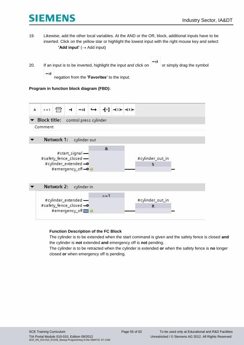
19. Likewise, add the other local variables. At the AND or the OR, block, additional inputs have to be
inserted. Click on the yellow star or highlight the lowest input with the right mouse key and select
’Add input’ ( Add input)
20. If an input is to be inverted, highlight the input and click on or simply drag the symbol
negation from the 'Favorites‘ to the input.
Program in function block diagram (FBD):
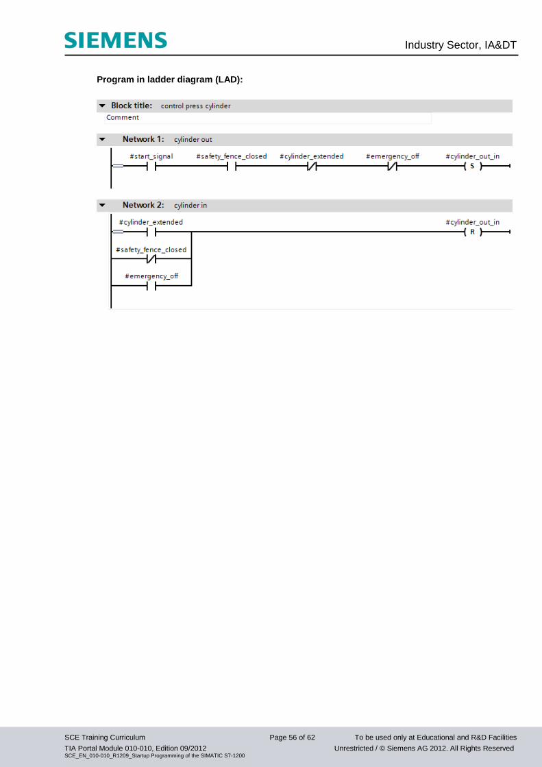
Function Description of the FC Block
The cylinder is to be extended when the start command is given and the safety fence is closed and
the cylinder is not extended and emergency off is not pending.
The cylinder is to be retracted when the cylinder is extended or when the safety fence is no longer
closed or when emergency off is pending.
Industry Sector, IA&DT
SCE Training Curriculum Page 56 of 62 To be used only at Educational and R&D Facilities
TIA Portal Module 010-010, Edition 09/2012 Unrestricted / © Siemens AG 2012. All Rights Reserved SCE_EN_010-010_R1209_Startup Programming of the SIMATIC S7-1200
Program in ladder diagram (LAD):
Industry Sector, IA&DT
SCE Training Curriculum Page 57 of 62 To be used only at Educational and R&D Facilities
TIA Portal Module 010-010, Edition 09/2012 Unrestricted / © Siemens AG 2012. All Rights Reserved SCE_EN_010-010_R1209_Startup Programming of the SIMATIC S7-1200
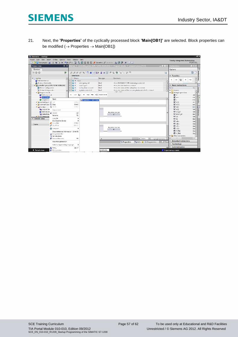
21. Next, the ’Properties’ of the cyclically processed block ’Main[OB1]’ are selected. Block properties can
be modified ( Properties Main[OB1])
Industry Sector, IA&DT
SCE Training Curriculum Page 58 of 62 To be used only at Educational and R&D Facilities
TIA Portal Module 010-010, Edition 09/2012 Unrestricted / © Siemens AG 2012. All Rights Reserved SCE_EN_010-010_R1209_Startup Programming of the SIMATIC S7-1200
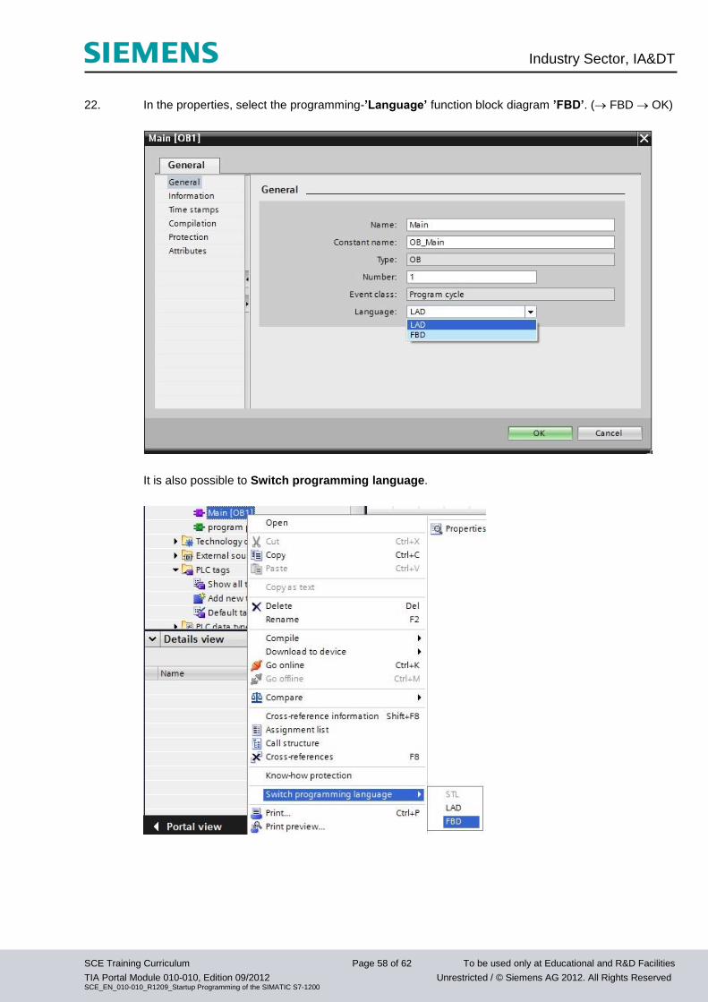
22. In the properties, select the programming-’Language’ function block diagram ’FBD’. ( FBD OK)
It is also possible to Switch programming language.
Industry Sector, IA&DT
SCE Training Curriculum Page 59 of 62 To be used only at Educational and R&D Facilities
TIA Portal Module 010-010, Edition 09/2012 Unrestricted / © Siemens AG 2012. All Rights Reserved SCE_EN_010-010_R1209_Startup Programming of the SIMATIC S7-1200
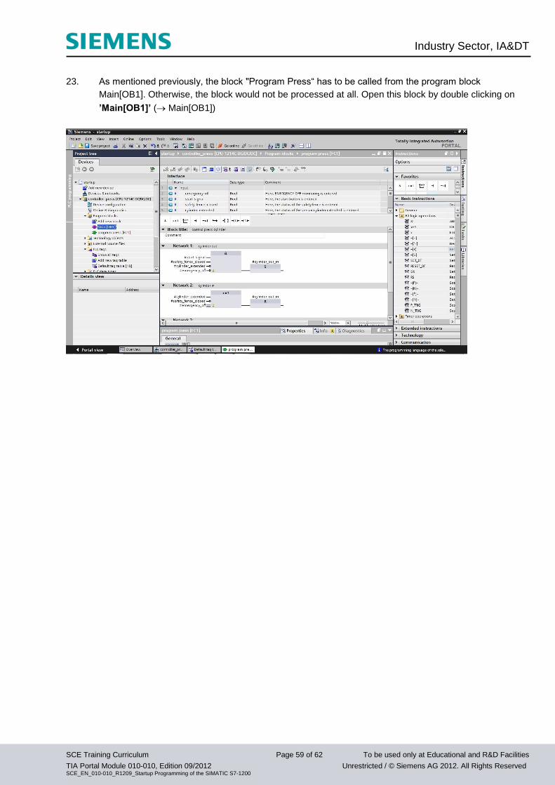
23. As mentioned previously, the block "Program Press“ has to be called from the program block
Main[OB1]. Otherwise, the block would not be processed at all. Open this block by double clicking on
’Main[OB1]’ ( Main[OB1])
Industry Sector, IA&DT
SCE Training Curriculum Page 60 of 62 To be used only at Educational and R&D Facilities
TIA Portal Module 010-010, Edition 09/2012 Unrestricted / © Siemens AG 2012. All Rights Reserved SCE_EN_010-010_R1209_Startup Programming of the SIMATIC S7-1200
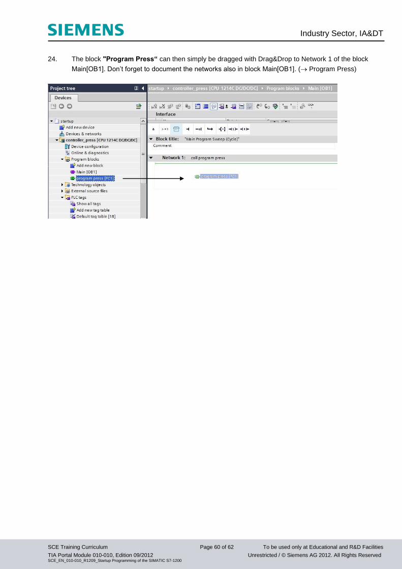
24. The block "Program Press“ can then simply be dragged with Drag&Drop to Network 1 of the block
Main[OB1]. Don’t forget to document the networks also in block Main[OB1]. ( Program Press)
Industry Sector, IA&DT
SCE Training Curriculum Page 61 of 62 To be used only at Educational and R&D Facilities
TIA Portal Module 010-010, Edition 09/2012 Unrestricted / © Siemens AG 2012. All Rights Reserved SCE_EN_010-010_R1209_Startup Programming of the SIMATIC S7-1200
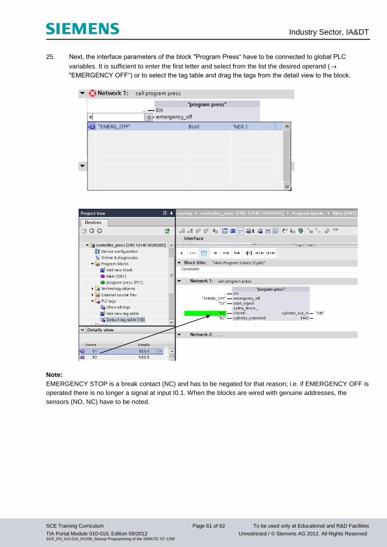
25. Next, the interface parameters of the block "Program Press“ have to be connected to global PLC
variables. It is sufficient to enter the first letter and select from the list the desired operand (
"EMERGENCY OFF“) or to select the tag table and drag the tags from the detail view to the block.
Note:
EMERGENCY STOP is a break contact (NC) and has to be negated for that reason; i.e. if EMERGENCY OFF is
operated there is no longer a signal at input I0.1. When the blocks are wired with genuine addresses, the
sensors (NO, NC) have to be noted.
Industry Sector, IA&DT
SCE Training Curriculum Page 62 of 62 To be used only at Educational and R&D Facilities
TIA Portal Module 010-010, Edition 09/2012 Unrestricted / © Siemens AG 2012. All Rights Reserved SCE_EN_010-010_R1209_Startup Programming of the SIMATIC S7-1200
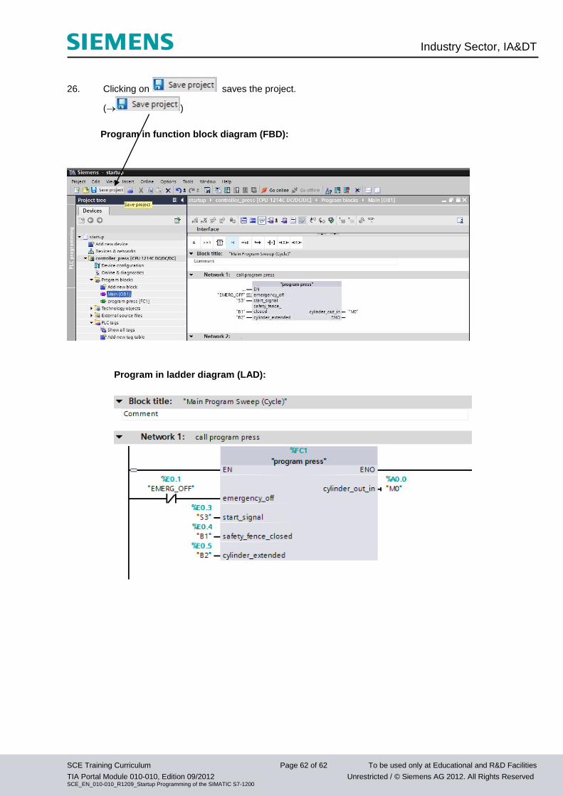
26. Clicking on saves the project.
( )
Program in function block diagram (FBD):
Program in ladder diagram (LAD):
Industry Sector, IA&DT
SCE Training Curriculum Page 63 of 62 To be used only at Educational and R&D Facilities
TIA Portal Module 010-010, Edition 09/2012 Unrestricted / © Siemens AG 2012. All Rights Reserved SCE_EN_010-010_R1209_Startup Programming of the SIMATIC S7-1200
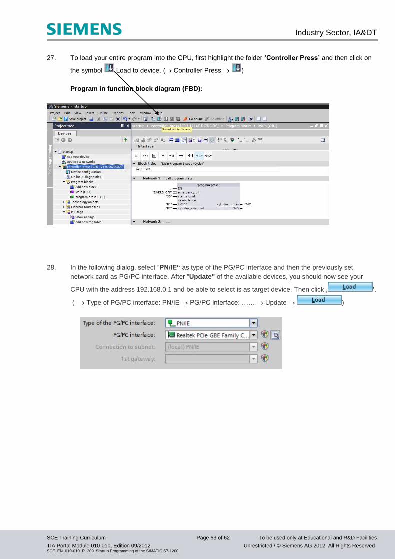
27. To load your entire program into the CPU, first highlight the folder ’Controller Press’ and then click on
the symbol Load to device. ( Controller Press )
Program in function block diagram (FBD):
28. In the following dialog, select “PN/IE“ as type of the PG/PC interface and then the previously set
network card as PG/PC interface. After "Update" of the available devices, you should now see your
CPU with the address 192.168.0.1 and be able to select is as target device. Then click ‚ ’.
( Type of PG/PC interface: PN/IE PG/PC interface: …… Update )
Industry Sector, IA&DT
SCE Training Curriculum Page 64 of 62 To be used only at Educational and R&D Facilities
TIA Portal Module 010-010, Edition 09/2012 Unrestricted / © Siemens AG 2012. All Rights Reserved SCE_EN_010-010_R1209_Startup Programming of the SIMATIC S7-1200
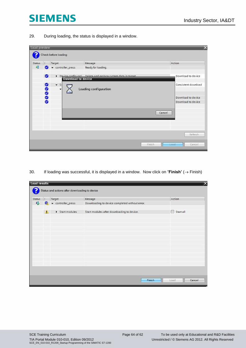
29. During loading, the status is displayed in a window.
30. If loading was successful, it is displayed in a window. Now click on ’Finish’ ( Finish)
Industry Sector, IA&DT
SCE Training Curriculum Page 65 of 62 To be used only at Educational and R&D Facilities
TIA Portal Module 010-010, Edition 09/2012 Unrestricted / © Siemens AG 2012. All Rights Reserved SCE_EN_010-010_R1209_Startup Programming of the SIMATIC S7-1200
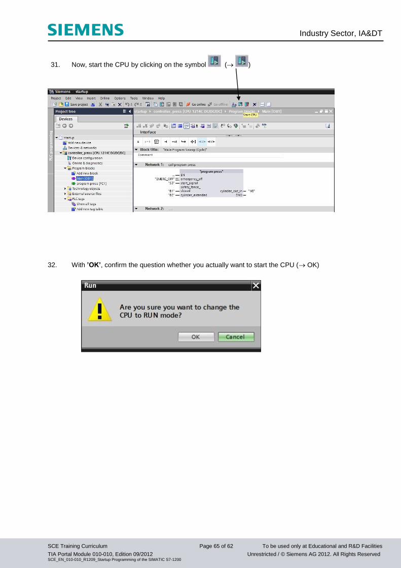
31. Now, start the CPU by clicking on the symbol ( )
32. With ’OK’, confirm the question whether you actually want to start the CPU ( OK)
Industry Sector, IA&DT
SCE Training Curriculum Page 66 of 62 To be used only at Educational and R&D Facilities
TIA Portal Module 010-010, Edition 09/2012 Unrestricted / © Siemens AG 2012. All Rights Reserved SCE_EN_010-010_R1209_Startup Programming of the SIMATIC S7-1200
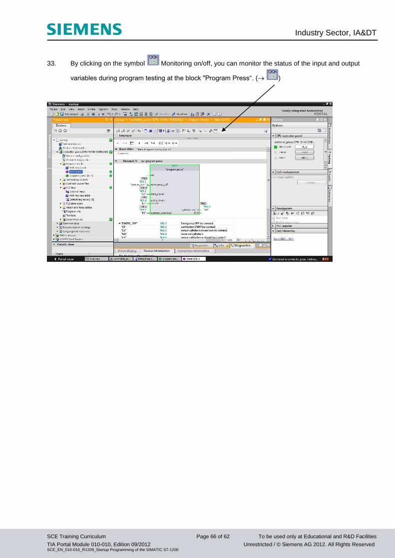
33. By clicking on the symbol Monitoring on/off, you can monitor the status of the input and output
variables during program testing at the block "Program Press“. ( )