Embed Size (px)
Citation preview
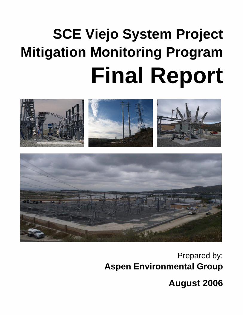
SCE Viejo System Project Mitigation Monitoring Program
Final Report
Prepared by: Aspen Environmental Group
August 2006

Southern California Edison Company’s
Viejo System Project
Mitigation Monitoring Program Final Report
Prepared for:
California Public Utilities Commission
Prepared by: Aspen Environmental Group
August 2006

SCE Viejo System Project CONTENTS
August 2006 i Final Report
Contents 1.0 Introduction and Project Overview .............................................................................................................. 1 1.1 Overview of the SCE Viejo System Project................................................................................................. 1 1.2 Role of Aspen Monitoring Team ................................................................................................................... 2 1.3 Pre-Construction Compliance Review and Notices to Proceed................................................................. 4 1.4 Compliance Monitoring................................................................................................................................... 5 1.5 Coordination and Communications................................................................................................................ 5 1.6 Variance Requests ............................................................................................................................................ 5
2.0 Viejo Substation..................................................................................................................................................... 7 2.1 Description of the Viejo Substation............................................................................................................... 7 2.2 Construction of the Viejo Substation............................................................................................................. 9 2.2.1 Notices to Proceed for the Viejo Substation ................................................................................. 9 2.2.2 Construction Highlights ................................................................................................................... 9 2.2.3 Revegetation Highlights ................................................................................................................. 12 2.3 Non-Compliance Events During Viejo Substation Construction............................................................. 13 2.4 Summary of the Viejo Substation Activities............................................................................................... 13 2.5 Final Inspection of the Viejo Substation ..................................................................................................... 13
3.0 220 kV Transmission Line Segment .......................................................................................................... 14 3.1 Description of the 220 kV Transmission Line ........................................................................................... 14 3.2 Construction of the 220 kV Transmission Line ......................................................................................... 14 3.2.1 Notices to Proceed for the 220 kV Transmission Line ............................................................. 14 3.2.2 220 kV Construction Highlights ................................................................................................... 14 3.2.3 Revegetation Highlights ................................................................................................................. 16 3.3 Non-Compliance Events During 220 kV Transmission Line Construction ........................................... 17 3.4 Summary of the 220 kV Transmission Line Activities............................................................................. 17 3.5 Final Inspection of the 220 kV Transmission Line ................................................................................... 18
4.0 66 kV Transmission Line Segment............................................................................................................. 19 4.1 Description of the 66 kV Transmission Line ............................................................................................. 19 4.2 Construction of the 66 kV Transmission Line ........................................................................................... 20 4.2.1 Notices to Proceed for the 66 kV Transmission Line................................................................ 20 4.2.2 Construction Highlights ................................................................................................................. 20 4.2.3 Revegetation Highlights ................................................................................................................. 23 4.3 Non-Compliance Events During 66 kV Transmission Line Construction ............................................. 23 4.4 Summary of the 66 kV Transmission Line Activities ............................................................................... 23 4.5 Final Inspection of the 66 kV Transmission Line ..................................................................................... 24
5.0 Conclusions and Recommendations........................................................................................................ 25 Agency Permit Coordination .................................................................................................................................... 25 Best Management Practices (BMPs)........................................................................................................................ 25

SCE Viejo System Project CONTENTS
August 2006 ii Final Report
Tables
Table 1 NTPS for Construction....................................................................................................................................... 5
Figures
Fig. 1-1 Regional Vicinity Map ....................................................................................................................................... 3
Fig. 2-1 Viejo Substation site prior to vegetation removal and grading activities .................................................... 7
Fig. 2-2 Fossil fish discovered on the Viejo Substation site by the LSA paleontological monitor, August 10, 2004 .................................................................................................................................................. 9
Fig. 2-3 Three Kings Construction excavates trench along main access road for fiber optic and 12 kV distribution lines, August 4, 2004................................................................................................................... 10
Fig. 2-4 Boring machine excavating foundations for supports in the Viejo Substation, September 30, 2004..................................................................................................................................................................... 10
Fig. 2-5 Firewalls constructed between the two A-bank transformers and between the transformers and MEER #1, January 11, 2005........................................................................................................................... 10
Fig. 2-6 Large crane brought to Viejo Substation to set B-bank transformers onto completed concrete pads, November 18, 2004................................................................................................................................ 10
Fig. 2-7 Crews worked inside MEER #1 on communication and control systems for the Viejo Substation, March 20, 2005 ................................................................................................................................................. 11
Fig. 2-8 Reycon Construction crews built the containment walls and the block wall surrounding the Viejo Substation after the foundations were placed by Union Construction, March 22, 2005.............. 11
Fig. 2-9 The substation electrical contractor, NRG, worked on the 12 kV switching system, March 22, 2005..................................................................................................................................................................... 12
Fig. 2-10 Arizona Pipeline installed the 12 kV distribution system and the fiber optic communication lines between the Viejo Substation and the local system, May 24, 2005 ........................................................... 12
Fig. 2-11 The 12 kV underground distribution conductor was connected to the switching system at the Viejo Substation, July 20, 2005 ...................................................................................................................... 12
Fig. 3-1 The drilling machine started the excavation of foundations for the 220 kV portion of the project, October 5, 2004................................................................................................................................................. 14
Fig. 3-2 Higher value native habitat was marked off to allow the crane and man-lifts to set up on the southern 220 kV tower, December 9, 2004 .................................................................................................. 15
Fig. 3-3 The access road between the southern 220 kV tower and the Viejo Substation was eroding due to natural drainage. Steel plates, and later rock, were placed to allow safe passage, October 5, 2004........ 15
Fig. 3-4 Crews used small cranes and man-lifts to raise the section of the new 220 kV towers above the Viejo Substation, November 18, 2004..................................................................................................... 15
Fig. 3-5 Crews used man-lifts and crane-supported baskets during stringing activities on the 220 kV section, December 17, 2004 ............................................................................................................................ 16
Fig. 3-6 Conductor dropped during the stringing of the 220 kV transmission line. SCE worked with the project biologist to remove the conductor with minimal environmental impact, December 30, 2004..................................................................................................................................................................... 16
Fig. 3-7 Non-native ruderal species emerged in the areas disturbed by the 220 kV transmission line construction and were removed by hand, July 5, 2005 ............................................................................... 17

SCE Viejo System Project CONTENTS
August 2006 iii Final Report
Fig. 3-8 Heavy rains and the use of inappropriate erosion prevention and sediment control devices led to sediment transport on the 220 kV transmission line right-of-way, December 30, 2004 ................. 17
Fig. 4-1 Native vegetation on 66 kV right-of-way prior to construction, May 2005 ............................................. 19
Fig. 4-2 New access roads and pads were required for the steel poles connecting the 66 kV right-of-way and the Viejo Substation, April 1, 2005 ........................................................................................................ 20
Fig. 4-3 The two excavation for H-Frame Structure 13 in the foreground were backfilled with slurry after improper placement, May 20, 2005. Note the contrast compared to Figure 4-1........................... 21
Fig. 4-4 Crews prepared to lower the rebar re-enforcing cage and anchor bolts into the foundation for H-Frame Structure 9 prior to concrete placement, June 14, 2005............................................................. 21
Fig. 4-5 A crew scaled H-Frame Structure 12 to guide the upper section into place and bolt it to the lower section, June 7, 2005 ............................................................................................................................. 21
Fig. 4-6 Crews worked with a crane and man-lifts to attach the cross members to H-Frame Structure 9, June 29, 2005..................................................................................................................................................... 21
Fig. 4-7 H-Frame Structure 13 completed with cross members and west set of arms, June 22, 2005................ 22
Fig. 4-8 Guard structures placed across residential road to prevent pulling rope from sagging onto road, September 26, 2005 .......................................................................................................................................... 22
Fig. 4-9 The pulling crew set up adjacent to the Chiquita Substation to pull the center circuit of the 66 kV transmission line, April 1, 2005.......................................................................................................... 22
Fig. 4-10 No recruitment of native (or ruderal) vegetation has been observed on the disturbed slope below H-Frame Structure 1, October 31, 2005 ............................................................................................ 23
SCE Viejo System Project
August 2006 1 Final Report
1.0 Introduction and Project Overview The Final Construction Completion Report has been developed to summarize the monitoring activities conducted for the Southern California Edison (SCE) Viejo System Project. The Viejo System Project included the construction of the Viejo Substation on a 12.5-acre site adjacent to State Route 241 in the City of Lake Forest, the addition of a new 3.1-mile 66 kV line between the Chiquita and the proposed Viejo Substations, the replacement of 19 double-circuit tubular steel poles with 13 H-frame structures, and the replacement of three 220 kV lattice towers to relocate 0.3 miles of 220 kV line into the Viejo Substation. The California Public Utilities Commission (CPUC) as the Lead Agency for the project con-ducted the environmental review process and granted final approval of the project. Aspen Environmental Group implemented the Mitigation Monitoring Program to ensure compliance with project mitigation measures, compliance plans, and permit conditions during all phases of construction.
Chapter 1, Introduction/Project Overview, provides a brief overview of the Viejo System Project and project approvals granted by the CPUC. In addition, Chapter 1 outlines the role and responsibility under-taken by Aspen Environmental Group as the mitigation monitoring team, including pre-construction compliance review. The methods established for addressing non-compliance issues, changes in the proj-ect description or mitigation implementation, and extra workspace requirements are also discussed.
The Viejo System Project was constructed as three distinct segments: the Viejo Substation discussed in Chapter 2; the modifications to the 220 kV transmission line discussed in Chapter 3; and the 66 kV transmission line discussed in Chapter 4.
Chapter 5 presents monitoring issues and recommendations for future mitigation monitoring plans.
Mainline construction of the Viejo System Project took place between July 2004 and December 2005, while final clean-up and revegetation/landscaping continue into 2006. The 220 kV portion of the project was energized on April 7, 2005. The 66 kV portion of the project was temporarily energized on June 6, 2005, on the existing circuitry and then on final energization on the new H-frame structures occurred on December 15, 2005.
1.1 Overview of the SCE Viejo System Project SCE’s objective with the Viejo System Project was to improve reliability and meet projected electrical load requirements in the rapidly urbanizing southern Orange County area. Southern Orange County’s electrical needs were previously served from SCE’s main electrical grid via the 220/66 kV Santiago Substation and the connecting distribution facilities, referred to as the Santiago System, which serves approximately 250,000-metered customers. Several substations located in the south and southeast regions of the Santiago System had become heavily loaded due to rapid growth in recent years.
The Viejo System Project was composed of four major components:
• Construction of the Viejo Substation on a 12.5-acre site adjacent to State Route 241 in the City of Lake Forest
• The addition of a new 3.1-mile 66 kV line between the Chiquita and the proposed Viejo Substations
• The replacement of 19 double-circuit tubular steel poles with 13 H-frame structures
• The replacement of three 220 kV lattice towers to relocate 0.3 miles of 220 kV line into the Viejo Substation

SCE Viejo System Project
August 2006 2 Final Report
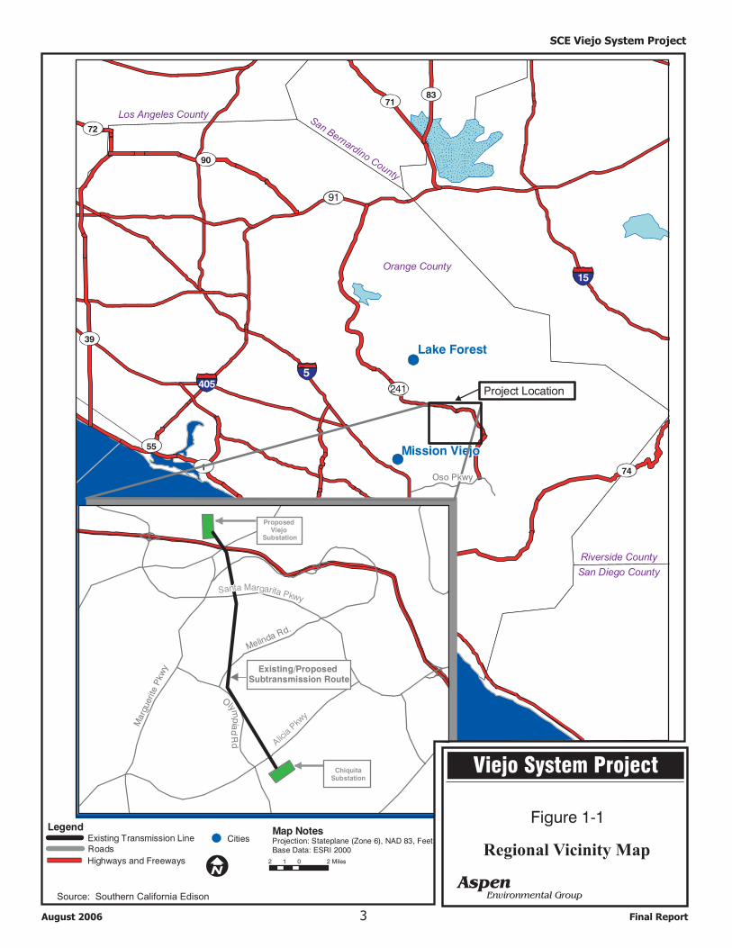
The Viejo System Project area includes the substation site and a 3.1-mile segment of the existing 220/66 kV transmission corridor located between the newly constructed Viejo Substation and the existing Chiquita Substation. The transmission corridor is located within the Cities of Lake Forest and Mission Viejo, and the Viejo Substation is located in the Foothill Ranch Planned Community within the City of Lake Forest (see Figure 1-1). All portions of the project were located in Orange County, California.
The Viejo Systems Project was approved by the California Public Utilities Commission and a Permit to Construct was issued on July 8, 2004 (Decision 04-07-027). The Mitigated Negative Declaration and Supporting Initial Study (Application number 03-03-043) was prepared by Aspen Environmental Group under contract to the CPUC in accordance with the California Environmental Quality Act (CEQA) to inform the public and to meet the needs of local, state, and federal permitting agencies in considering the project proposed by SCE.
1.2 Role of Aspen Monitoring Team The Aspen Monitoring Team was composed of the Program Manager (Jon Davidson), Project Manager (Vida Strong), and the following Environmental Monitors (EM):
• Christopher Meyer (Lead EM)
• Jenny Slaughter (EM)
Aspen’s Program Manager, Jon Davidson, had the authority to commit Aspen Team resources and was responsible for all contractual matters.
Aspen’s Project Manager, Vida Strong, supervised all project monitoring activities. She was respon-sible for direct communication with the CPUC, including preparation of weekly reports. Other responsibilities included managing the field monitoring team, reviewing non-compliance documentation, and preparing recommendations for CPUC consideration on Project Notices to Proceed.
The CPUC Lead EM reviewed pre-construction compliance materials for completeness and performed in-field monitoring for compliance with mitigation measures, approved plans, and agency requirements during all construction activities. In the field, he served as the main point of contact for SCE, as well as for a variety of Federal, State, and local agencies. The CPUC Lead EM also attended meetings held by SCE and its contractors. The Lead EM also performed in-field monitoring and was supported by the CPUC EM. The CPUC Lead EM and CPUC EM prepared and submitted daily and weekly compliance reports to the Aspen Project Manager.
The CPUC EMs have been trained in a number of disciplines including environmental science, biology, and archaeology and are experienced in compliance monitoring. CPUC EMs conducted the majority of the monitoring on a random, one day per week basis, but were available to address specific compliance issues outside this once-weekly monitoring schedule.
Project Location
5
405
15
74
39
7183
90
1
133
72
55
Regional Vicinity Map
xd
241
Orange CountyOrange County
Mission ViejoMission Viejo
Lake ForestLake Forest
San Bernardino County
San Bernardino County
Los Angeles CountyLos Angeles County
Riverside CountyRiverside County
San Diego CountySan Diego County
ProposedViejo
Substation
ChiquitaSubstation
Map NotesProjection: Stateplane (Zone 6), NAD 83, FeetBase Data: ESRI 2000
2 0 21 Miles
5
Existing/ProposedSubtransmission Route
91
Santa Margarita PkwySanta Margarita Pkwy
Alicia
Pkwy
Alicia
Pkwy
Melinda Rd.
Melinda Rd.
Olymp
iad
Rd
Olymp
iad
Rd
Marg
uerite
Pkw
y
Marg
uerite
Pkw
y
LegendExisting Transmission Line CitiesRoads
Highways and Freeways
Oso PkwyOso Pkwy
AspenEnvironmental Group
Figure 1-1
Regional Vicinity Map
Viejo System Project
Source: Southern California Edison
SCE Viejo System Project
3 Final ReportAugust 2006
SCE Viejo System Project
August 2006 4 Final Report
1.3 Pre-Construction Compliance Review and Notices to Proceed SCE submitted a Worker Environmental Awareness Plan (WEAP), which outlined the Company’s approach to assuring compliance with the mitigation measures applicable to the Viejo Systems Project. In addi-tion, several specific compliance plans were submitted to satisfy Federal and State agency requirements, including:
• Worker Environmental Awareness Plan • Storm Water Pollution Prevention Plan • Erosion Control Plan • Hazardous Materials Business Plan • Cultural Resources Plan • Restoration Plan
These compliance plans were reviewed by Aspen prior to the start of construction to ensure that appropriate environmental protection would take place. In addition, Aspen tracked the necessary permitting require-ments to ensure that all the applicable agency permits had been issued prior to construction. Permits issued for the project included:
State: • California Public Utilities Commission: Permit to Construct; Notice to Proceed • California Department of Transportation: Encroachment Permit
Regional: • Regional Water Quality Control Board (RWQCB): Section 402 National Pollutant Discharge Elimi-
nation System (NPDES) Construction Activity General Permit
Local: • City of Lake Forest: Site Development Permit; Transportation Permit; Encroachment Permit • City of Mission Viejo: Encroachment Permit
SCE conducted pre-construction surveys as outlined in the Central and Coastal Natural Community Conservation Plan (NCCP) to quantify the number of foothill mariposa lilies present prior to commencing construction. No populations were noted in the survey. SCE provided documentation that pre-construction surveys have been completed for foothill mariposa lily on September 10, 2004. CPUC reviewed the documentation provided by SCE and verified that no foothill mariposa lilies were present in the areas scheduled to be impacted by the project. An Environmental Inspector representing SCE was present during initial construction activities. Surveys for coastal California gnatcatchers, coastal cactus wrens, and southern California rufous-crowned sparrows were conducted on September 17, 2004, by LSA Associates’ biologists prior to the start of grading in all areas of coastal sage scrub and within 100 feet of the outer extent of project soil disturbance activities in accordance with the NCCP minimization/mitigation measures. In accordance with the provisions of the Central and Coastal NCCP a monitoring biologist was on-site during any clearing of coastal sage scrub.
No significant archaeological resources were identified at the Viejo Substation site or within the corri-dor of the 220/66 kV Transmission Line. All construction personnel were trained regarding the poten-tial for presently unknown cultural resources and the procedures to treat unexpected discoveries. An archaeologist/paleontologist representing SCE was present during all of the underground excavation and construction. No significant unanticipated discoveries of cultural resources occurred.

SCE Viejo System Project
August 2006 5 Final Report
As part of the SCE Viejo System Worker Environmental Awareness Plan, all employees working on the project were required to attend an environmental training session before they could begin work. SCE’s environmental representatives presented the training session, which covered environmental and cultural resource issues, state and federal laws, and reporting procedures.
When necessary pre-construction com-pliance documentation was satisfactorily submitted, recommendations for Notices to Proceed (NTPs) were prepared by Aspen for CPUC consideration. A total of four NTPs for Construction were issued by the CPUC for the Viejo Sys-tem Project (see Table 1). Once ap-provals from other agencies were re-ceived, construction could commence in accordance with the NTPs for Construc-tion and issued permits.
1.4 Compliance Monitoring Compliance monitoring by the CPUC EMs was intended to chronicle and document SCE’s compliance with project mitigation measures, compliance plans, and permit conditions. Compliance monitoring was implemented to minimize or eliminate potential significant impacts and to protect environmental resources. A Non-Compliance was defined as “any deviation from applicable mitigation measures, applicant-proposed measures and project parameters, permit conditions or requirements, and approved plans.” A Project Memorandum would be a written warning of a non-compliance activity. Non-Compli-ance Reports would be issued when chronic non-compliance activity occurred or a blatant disregard for project mitigation measures, compliance plans, or permit conditions was demonstrated. Project Memoranda and Non-Compliance Reports are typically issued after an initial verbal warning. Compli-ance issue on the Viejo Systems Project were able to be address with only verbal warnings and no Proj-ect Memoranda or Non-Compliance Reports were necessary.
1.5 Coordination and Communications In field communications were conducted by the CPUC EMs with SCE’s Environmental Inspectors and other project personnel. Verbal warnings proved satisfactory to notify SCE and its contractors of poten-tial non-compliance activities. Field observations were logged daily by the CPUC EMs. Weekly reports were submitted to CPUC and other agencies documenting compliance, requested project changes, con-struction progress, and interactions with other agencies. The weekly reports were posted on the CPUC project web site.
1.6 Variance Requests Variance Requests could have been submitted by SCE to the CPUC for changes in the approved project description, including changes in construction technique, additional extra workspace needs, or reduction in mitigation requirements. Any Variance Request submitted by SCE would have been first reviewed by Aspen for completeness. If incomplete, a request for information would have been prepared by Aspen
Table 1. NTPS for Construction
CPUC NTPs Date Issued NTP #1 Construction of the Viejo Substation July 14, 2004
NTP #2 Construction of the 220 kV portion Sept. 29, 2004
NTP #3 Construction of the 66 kV portion adjacent to the Viejo substation site
Jan. 31, 2005
NTP #4 Construction of the 66 kV portion between the Viejo and Chiquita substations
April 18, 2005

SCE Viejo System Project
August 2006 6 Final Report
and sent to SCE. When complete, each request would have been analyzed, including field verification and resource/local agency consultation, to determine if new impacts or an increase in significant im-pacts would result. After analysis of the request, Aspen would have prepared a written recommendation of approval or denial for the CPUC. As appropriate, mitigation measures or other agency conditions would be required by the CPUC to avoid, or reduce to a less than significant level, any identified impacts. No Variance Requests were submitted by SCE for the Viejo System Project during the moni-toring period.

SCE Viejo System Project
August 2006 7 Final Report
2.0 Viejo Substation 2.1 Description of the Viejo Substation The 12.5-acre Viejo Substation site is located on land owned by SCE and is adjacent to the existing 220 kV corridor in the City of Lake Forest. The substation site is located in the foothills of the Santa Ana Mountains whose highest peaks are located approximately 10 to 15 miles north and east of the project area. The site is bordered by vacant land (Viejo Conservation Bank) on the east, on the south by vacant land owned by Orange County, on the north by light industrial development, and on the west by the SR 241 Foothill Transportation Corridor. The site of the Viejo Substation was zoned Light Industrial within the Foothill Ranch Planned Community, compatible with the substation construction.
The Viejo Substation site was previously graded and vacant, including disturbed habitat consisting of white clover, star thistle, and telegraph weed (see Figure 2-1). Mulefat, coyote bush, common tarweed, and buckwheat occurred in small populations scattered intermittingly across the site. The area is sur-rounded by existing office and technology parks and undeveloped lands characterized by scrub vegetation and the nearby Edison Trail to the east. This portion of the trail is above the elevational grade of the sub-station site and passes though undeveloped lands domi-nated by low-growing vegetation. Biological resources located in this area are typical of species common to the peninsular ranges of southern California and are adapted to a Mediterranean climate with cool wet win-ters and hot dry summers. Sage scrub communities occur in the area adjacent to the Viejo Substation and were once the dominant community in the project area. Urban development has encroached into the surround-ing foothills removing much of the previous habitat.
The Viejo Substation and transmission right-of-way to El Toro Road is located in the County of Orange Central and Coastal Subregion NCCP and Habitat Conservation Plan, of which SCE is a participating member. This area consists of approximately 325 square miles and includes the central portion of the County of Orange and extends to Riverside County. The primary goal of the NCCP is to protect and manage habitat supporting a broad range of plant and animal populations that are now found within the Central and Coastal Subregion. Specifically, this plan addresses impacts to sage scrub communities and several sensitive plant and animal species that are known to occur within the Viejo System area. These include the California gnatcatcher (Polioptila californica californica), coastal cactus wren (Camphylo-rhynchus brunneicapillus), and orange-throated whiptail (Cnemidophorus hyperythrus beldingi).
The Viejo Substation is an unmanned, automated, low-profile substation. The substation site contains two 220 kV source lines, two 280 Megavolt-Ampere (MVA) 220/66 kV transformers, five 66 kV sub-transmission lines, two 28 MVA 66/12 kV transformers, two 28.8 Megavolt-Ampere Reactive (MVAR) 66 kV capacitor banks, two 4.8 MVAR 12 kV capacitor banks, and four 12 kV distribution circuits. This substation is unusual in that it contained both transmission (220/66 kV) and distribution (12 kV) com-ponents. Two mechanical and electrical equipment rooms (MEER) were constructed to house control and relay panels, batteries and battery chargers, telecommunication and associated equipment. MEER #1
Figure 2-1. Viejo Substation site prior to vegetation removal and grading activities

SCE Viejo System Project
August 2006 8 Final Report
housed the controls for the distribution components of the site and operated as the main control building for the site. The much smaller MEER #2 was linked to MEER #1 and housed the controls for the distri-bution components for the site.
Landscaping around the substation has been designed to filter views from residential area located to the north and east of the site. The Landscape Plan included an eight-foot-high block wall surrounding three sides of the substation with security barbed wire mounted on the substation side of the wall. The side of the substation which faces the 220 kV corridor has an eight-foot-high, chain link fence topped with barbed wire. SCE has verbally proposed tentative changes to the type of vegetation used to visually screen the substation from the adjacent Edison Trail. These changes in vegetation type would be to find tree species that are compatible with the plants in the adjacent Viejo Conservation Bank land. This screening has not been placed at this time and the changes to the Landscape Plan have not been submitted to the CPUC for review and/or approval. Part of the delay is due to delays in the local approval of the water supply line to the facility, which would charge a fire hydrant adjacent to the facil-ity as well as provide water for landscaping. The codes that govern the class of pipe required for the fire hydrant have changed since the original design of the project and the class of pipe specified in the old codes was partially installed. This partially completed pipeline was removed and the trench line along the main access road was backfilled in order to complete restoration of the main access road. This issue was still open at the end of construction monitoring on the project.
The Viejo Substation has both security and maintenance lighting. The security lights are low intensity lights integrated into the landscape and architectural aspects of the station, and operate from dusk until dawn. Maintenance lighting consists of high-pressure sodium lights located in switchracks, around the transformer banks, and in areas of the yard where maintenance activities have to take place during night hours. Maintenance lights are controlled by a manual switch and will be operated only during times of maintenance activities.
During construction of the Viejo System Project, SCE installed two fiber optic cables to provide a ground return path for lightening protection and to provide SCE with a means of communication for voice, data, and relay protection. One Optical Ground Wire (OPGW) was installed between the Viejo and Chiquita Substations on the new 66 kV subtransmission H-frame structures and 4.4 miles of fiber optic cable was installed between the Viejo Substation and the Irvine Operation Center (IOC). The underground installation included the use of existing vaults and conduit (between the IOC and Portola Parkway) and three-quarters of a mile of newly constructed vaults and conduit (between Portola Parkway and the Viejo Substation). All new telecommunication structures and conduit were installed either in a franchise position within the public street or within SCE property. The addition of this fiber optic cable allows the Viejo Substation to be monitored and controlled by an existing power manage-ment system located at SCE’s Ellis Substation in the City of Huntington Beach.
Concurrent with the construction of the new three-quarters of a mile trench line and vaults for the fiber optic system between the Viejo Substation and Portola Parkway, SCE installed 12 kV distribution con-ductor to tie into the existing vault and conduit system.

SCE Viejo System Project
August 2006 9 Final Report
2.2 Construction of the Viejo Substation
2.2.1 Notices to Proceed for the Viejo Substation Notice to Proceed (NTP) #1 was issued by the CPUC for the construction of the Viejo Substation on July 14, 2004 (see Table 1).
2.2.2 Construction Highlights NTP #1 for work on the substation site was issued by the CPUC on July 14, 2004: however, grading operations did not begin until the following week, once SCE obtained the grading permit from the City of Lake Forest. The LSA Environmental Inspector (EI) and the paleontological inspector were on-site to review the pre-construction status of the substation site with the CPUC EM. The LSA EI walked the site ahead of grubbing to flush whiptail lizards out of the project area. The sensitive resources on the hillside are separated from the construction activities by a cyclone fence.
The entire 12.5-acre substation site was stripped of vegetation and soil to a depth of eight inches. The stripped material was stored on-site until it was filtered and replaced as backfill. The bottom of the stripped pad was scarified to a minimum depth of six inches and brought to a minimum moisture content per American Society of Testing Materials (ASTM) standards. Of the approximately 13,000 cubic yards of soil removed from the pad, 9,000 cubic yards was used to back fill the surface. The balance of the fill material was placed in a large spoil pile in the adjacent laydown area and was to be hauled off-site. However, this material was recently spread over the temporary laydown area without CPUC approval. SCE has been requested to provide information on the stabilization and erosion control of this material. Following final grading and the excavation of major pads and foundations, a four-inch layer of untreated crushed rock was placed within the walled substation area, except in designated driveways.
The paleontological inspector was on-site to monitor grading activities at the substation site. Several fossils were discovered during grading activities including a fish fossil and a fragment of sea cow bone (see Figure 2-2). The pad for the site has been severely disturbed and it is likely that some of the fossils have been moved from their original location prior to the start of project construction. Nonetheless, some of the fossils discovered during vertical boring for founda-tion structures are likely to have been discovered in situ.
Construction of the perimeter fences, foundations, and below ground facilities (e.g., grounding grid, con-duit, etc.) took place after the site was prepared and graded. Installation of the aboveground structures and electrical equipment followed. All material for the substation was delivered by truck. Water and rock was used along the access road to control dust.
The first excavation on the project was started the week of August 1, 2004, for the electrical conduit between the Viejo Substation site and main gate (see Figure 2-3). This conduit was damaged during the backfill operation and sections were re-excavated later in the project for repair. Following the initial
Figure 2-2. Fossil fish discovered on the Viejo Substation site by the LSA paleontological monitor, August 10, 2004

SCE Viejo System Project
August 2006 10 Final Report
grading of the substation site, the grounding grid was placed throughout the site starting on August 16, 2006. Each structure in the facility was connected to this grid, including the fencing and walls that surrounded the site.
After the completion of the grounding grid, a vertical drilling machine was used to bore the numerous foun-dations that were required for the poles and other structures at the facility (see Figure 2-4). The drilling progressed slowly due to the hardness of the native material. Foundations were excavated, formed and con-crete placed for the transformer pads, MEER #1 and MEER #2, as well as for other smaller concrete pads.
The construction of the two firewalls, one between the first A-bank (220 kV to 66 kV) transformer and MEER #1 and the other between the two A-bank transformers, were completed by October 15, 2004 (see Figure 2-5). These firewalls both protect workers in MEER #1 in the case of a transformer fire, but also help prevent a fire from spreading between the two A-bank transformers.
On November 18, 2004, a crew worked with a 300-ton crane to set the B-bank (66 kV to 12 kV) trans-formers on their foundations (see Figure 2-6). The crane arrived on-site without counterweights and was not able to extend the boom more than a few degrees away from center. This problem required the
Figure 2-3. Three Kings Construction excavates trench along main access road for fiber optic and 12 kV distribution lines, August 4, 2004
Figure 2-4. Boring machine excavating foundations for supports in the Viejo Substation, September 30, 2004
Figure 2-5. Firewalls constructed between the two A-bank trans-formers and between the transformers and MEER #1, January 11,2005
Figure 2-6. Large crane brought to Viejo Substation to set B-bank transformers onto completed concrete pads, November 18, 2004

SCE Viejo System Project
August 2006 11 Final Report
crew to move the transformers in two steps, with the crane located as close as possible to the foundations. The two A-bank transformers were delivered to the substation site by special trucks the week of Decem-ber 19, 2004. Much of the substation equipment had been delivered and placed on the poured founda-tions by this time.
During 2005, work within the substation site focused on conditioning the transformers, constructing the inte-rior components of the MEER #1 and MEER #2, and building the switching equipment (see Figure 2-7). Work on the installing the switching equipment, string-ing conductor, and testing the facility components also occurred at this time.
In March of 2005, Union Construction completed the excavation and placement of the concrete foundation for the block wall that shielded three sides of the sub-station site. SCE increased the width of the founda-tion for increased stability in the wall. A specialized crew set the concrete blocks for both the exterior wall and the smaller spill containment wall in March and April of 2005 (see Figure 2-8). The smaller spill con-tainment wall was specially coated to prevent the spreading of any petroleum spills and direct any spilled material into a special containment area for proper dis-posal. The wall was grouted to approximately 3 feet in elevation, when work was delayed briefly while wait-ing for an inspection by the city building department.
Construction of the 12 kV distribution system was one of the final phases of construction at the Viejo Sub-station (see Figure 2-9). The facility is unique in that it has transmission, subtransmission, and distribution components at one site. The switches were connected to conductor from the B-bank transformers and trans-ferred 12 kV power to both the local distribution sys-tem and back into the substation for both housekeep-ing current and backup power to restart operations.
The roads within the substation site had been asphalted by Saturday, August 13, 2005. The road contractor worked on Saturday to pave all the roads within the substation site without disruption of other construction activities and to minimize traffic impacts to the adjacent business park. Some of the corners were con-sidered too sharp by SCE and the radius at these locations was corrected. In addition to the asphalt repairs, the road contractor placed additional rock on the margins of the roads within the substation site.
Fiber Optic and 12 kV Underground Installation
The installation of the fiber optic system was completed in concert with the installation of the 12 kV under-ground distribution line that connected the Viejo Substation to the local distribution network. This con-struction activity occurred within the city streets in Lake Forest and included the installation of vaults as
Figure 2-7. Crews worked inside MEER #1 on communication andcontrol systems for the Viejo Substation, March 20, 2005
Figure 2-8. Reycon Construction crews built the containment walls and the block wall surrounding the Viejo Substation after the foun-dations were placed by Union Construction, March 22, 2005
SCE Viejo System Project
August 2006 12 Final Report
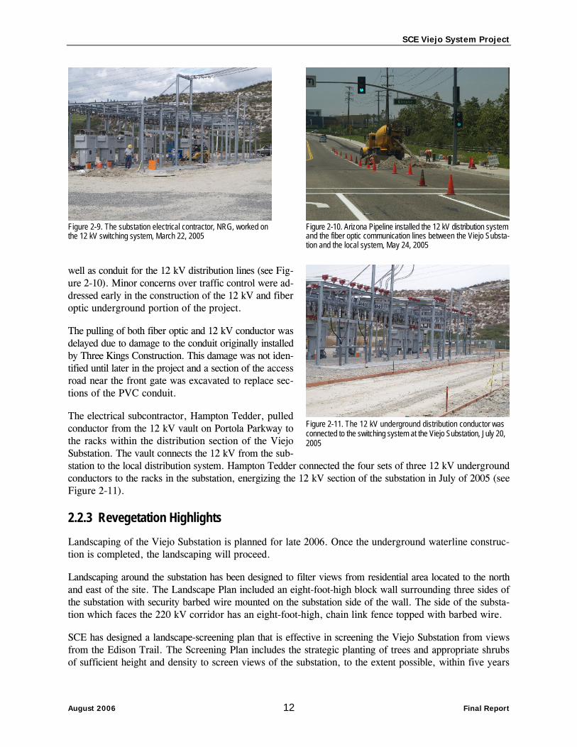
well as conduit for the 12 kV distribution lines (see Fig-ure 2-10). Minor concerns over traffic control were ad-dressed early in the construction of the 12 kV and fiber optic underground portion of the project.
The pulling of both fiber optic and 12 kV conductor was delayed due to damage to the conduit originally installed by Three Kings Construction. This damage was not iden-tified until later in the project and a section of the access road near the front gate was excavated to replace sec-tions of the PVC conduit.
The electrical subcontractor, Hampton Tedder, pulled conductor from the 12 kV vault on Portola Parkway to the racks within the distribution section of the Viejo Substation. The vault connects the 12 kV from the sub-station to the local distribution system. Hampton Tedder connected the four sets of three 12 kV underground conductors to the racks in the substation, energizing the 12 kV section of the substation in July of 2005 (see Figure 2-11).
2.2.3 Revegetation Highlights Landscaping of the Viejo Substation is planned for late 2006. Once the underground waterline construc-tion is completed, the landscaping will proceed.
Landscaping around the substation has been designed to filter views from residential area located to the north and east of the site. The Landscape Plan included an eight-foot-high block wall surrounding three sides of the substation with security barbed wire mounted on the substation side of the wall. The side of the substa-tion which faces the 220 kV corridor has an eight-foot-high, chain link fence topped with barbed wire.
SCE has designed a landscape-screening plan that is effective in screening the Viejo Substation from views from the Edison Trail. The Screening Plan includes the strategic planting of trees and appropriate shrubs of sufficient height and density to screen views of the substation, to the extent possible, within five years
Figure 2-9. The substation electrical contractor, NRG, worked on the 12 kV switching system, March 22, 2005
Figure 2-10. Arizona Pipeline installed the 12 kV distribution system and the fiber optic communication lines between the Viejo Substa-tion and the local system, May 24, 2005
Figure 2-11. The 12 kV underground distribution conductor was connected to the switching system at the Viejo Substation, July 20, 2005

SCE Viejo System Project
August 2006 13 Final Report
of completion of construction. Minor changes to the type of trees approved in the Landscape Plan are expected and will require CPUC approval prior to implementation. SCE informed the CPUC Lead EM that species more compatible with the surrounding habitat conservation area are being considered to replace some of the plant species identified in the Landscape Plan. SCE informed the CPUC EM that landscaping is scheduled to start in the middle of August 2006.
2.3 Non-Compliance Events During Viejo Substation Construction No Non-Compliance events were observed during construction of the Viejo Substation. After the com-pletion of construction activities and the end of CPUC monitoring, the CPUC EM was notified that the excess spoils stored temporarily in the laydown area south of the substation site had been spread out rather than being hauled off-site. SCE has been requested to provide the CPUC will details on the sta-bilization of this spoil and on the prevention of erosion or sediment transport.
2.4 Summary of the Viejo Substation Activities The construction of the Viejo Substation occurred in a previously disturbed and graded area, minimiz-ing the potential for environmental issues. One NTP was issued by the CPUC for the construction of the Viejo Substation. SCE had requested that authorization to construct the substation and 220 kV Transmis-sion Line be provided separately from the 66 kV Transmission Line to allow construction to proceed while additional pre-construction compliance requirements were being satisfied. Construction was allowed to begin on July 14, 2004, after the issuance of the CPUC NTP for Construction and documentation was received from local agencies regarding applicable permits. Construction was conducted from July 2004 to January 2006, and involved the installation of 220 kV to 66 kV transformers, 66 kV to 12 kV trans-formers, and the associated switching and control facilities. Overall, construction proceeded smoothly despite delays due to the abnormally heavy rainfall in the winter of 2004/2005.
Compliance issues in the substation site were minimal and were mostly related to the biological sensi-tivity of the area and human land use of the area. Fugitive dust was a minor issue and was a potential nui-sance to employees working in the business parks, as well as water quality issues from turbid water leav-ing the site during storm events. The turbid water entering either storm drains or off-site v-ditches was primarily an issue due to the unusually heavy and constant rain events of the winter of 2004/2005 as well as the initial use of fiber rolls instead of silt fencing on portions of the project. Verbal warnings by the CPUC EM were sufficient to address all compliance concerns during substation site construction. SCE was very responsive to issues raised by the CPUC EM as well as addressing issues noted by SCE inspectors and crews. No Non-Compliances or Project Memoranda were issued during construction of the Viejo Substation.
No Variances were requested by SCE for the Viejo Substation construction. Between the areas approved in NTP #1 and the existing access roads and disturbed right-of-way, no requests were required or sub-mitted for additional work space.
2.5 Final Inspection of the Viejo Substation The CPUC EM conducted the final inspection of the Viejo Substation on April 10, 2006. Clean-up efforts were observed to be complete. Project flagging and signage was removed from the right-of-way, access roads, and ancillary sites. Landscaping around the Viejo Substation is planned for the middle of August of 2006.

SCE Viejo System Project
August 2006 14 Final Report
3.0 220 kV Transmission Line Segment 3.1 Description of the 220 kV Transmission Line The 220 kV portion of the Viejo System Project involved minor modifications to the existing 220 kV Chino–San Onofre and the San Onofre–Serrano transmission lines. These modifications included the replace-ment of three 220 kV Lattice Steel Towers (LSTs) and the installation of 10 Tubular Steel Poles (TSPs) to loop the Chino–San Onofre 220 kV circuit into the Viejo Substation and create a by-pass for the San Onofre–Serrano 220 kV circuit.
Habitat surrounding the 220 kV portion of the project is dominated by sage scrub and southern cactus scrub. Dominant species in these communities include buckwheat, California sagebrush, various sages, and prickly pear. These communities have the potential to support several sensitive wildlife species including California gnatcatcher, California horned lark (Eremophila aplestris actia), coastal cactus wren, and orange-throated whiptail.
3.2 Construction of the 220 kV Transmission Line
3.2.1 Notices to Proceed for the 220 kV Transmission Line NTP #2 was issued by the CPUC for the construction of the 220 kV portion of the project on Septem-ber 29, 2004 (see Table 1).
3.2.2 220 kV Construction Highlights Excavation was required for LST bases, crane pads, material laydown and assembly areas, and stub roads. In general, two separate crane pads were required for each LST site. One crane pad was also required for each of two clusters of three TSPs needed for construction of the 220 kV transmission line bypass recon-figuration of the San Onofre–Serrano 220 kV circuit. Following the preparation of the assembly area and access roads, footings were installed, towers were erected, and conductor was strung.
A drilling machine started working on the pole founda-tions starting on October 4, 2004 (see Figure 3-1). The drilling machine spent the entire first week working on one foundation bore due to the hardness of the rock. The spoils from the drilling operation were trucked back to the substation site for removal. Iron workers worked concurrently with the drilling to prepare the rebar cages for the 220 kV transmission line foundations on-site at each LST location.
In October of 2004, SCE discovered that one of the crane pads was not properly situated for the crane and requested a modification of the exclusion area. The CPUC EM returned to the site and reviewed the SCE
Figure 3-1. The drilling machine started the excavation of founda-tions for the 220 kV portion of the project, October 5, 2004
SCE Viejo System Project
August 2006 15 Final Report
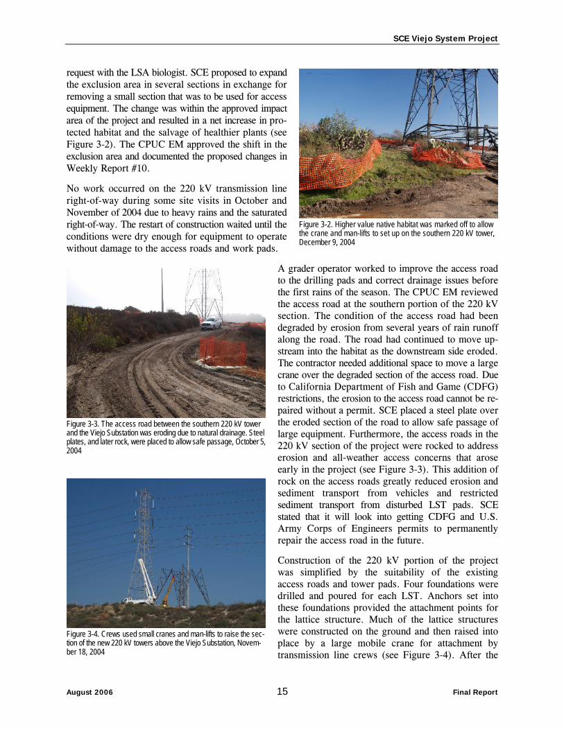
request with the LSA biologist. SCE proposed to expand the exclusion area in several sections in exchange for removing a small section that was to be used for access equipment. The change was within the approved impact area of the project and resulted in a net increase in pro-tected habitat and the salvage of healthier plants (see Figure 3-2). The CPUC EM approved the shift in the exclusion area and documented the proposed changes in Weekly Report #10.
No work occurred on the 220 kV transmission line right-of-way during some site visits in October and November of 2004 due to heavy rains and the saturated right-of-way. The restart of construction waited until the conditions were dry enough for equipment to operate without damage to the access roads and work pads.
A grader operator worked to improve the access road to the drilling pads and correct drainage issues before the first rains of the season. The CPUC EM reviewed the access road at the southern portion of the 220 kV section. The condition of the access road had been degraded by erosion from several years of rain runoff along the road. The road had continued to move up-stream into the habitat as the downstream side eroded. The contractor needed additional space to move a large crane over the degraded section of the access road. Due to California Department of Fish and Game (CDFG) restrictions, the erosion to the access road cannot be re-paired without a permit. SCE placed a steel plate over the eroded section of the road to allow safe passage of large equipment. Furthermore, the access roads in the 220 kV section of the project were rocked to address erosion and all-weather access concerns that arose early in the project (see Figure 3-3). This addition of rock on the access roads greatly reduced erosion and sediment transport from vehicles and restricted sediment transport from disturbed LST pads. SCE stated that it will look into getting CDFG and U.S. Army Corps of Engineers permits to permanently repair the access road in the future.
Construction of the 220 kV portion of the project was simplified by the suitability of the existing access roads and tower pads. Four foundations were drilled and poured for each LST. Anchors set into these foundations provided the attachment points for the lattice structure. Much of the lattice structures were constructed on the ground and then raised into place by a large mobile crane for attachment by transmission line crews (see Figure 3-4). After the
Figure 3-2. Higher value native habitat was marked off to allow the crane and man-lifts to set up on the southern 220 kV tower, December 9, 2004
Figure 3-3. The access road between the southern 220 kV tower and the Viejo Substation was eroding due to natural drainage. Steel plates, and later rock, were placed to allow safe passage, October 5,2004
Figure 3-4. Crews used small cranes and man-lifts to raise the sec-tion of the new 220 kV towers above the Viejo Substation, Novem-ber 18, 2004

SCE Viejo System Project
August 2006 16 Final Report
CPUC EM reviewed the area with the SCE biologist and the LSA Environmental Inspector, SCE moved the exclusion fencing near the southern tower location on December 20, 2004 to move a crane to the north side of the tower to set the eastern lattice sections. The SCE biologist examined the habitat and moni-tored all vegetation clearing. SCE placed plating over the habitat and avoided the mature sage and cactus, using a sparsely vegetated corridor for access. The SCE needed a minor expansion in the work area on the east side of this tower as well to place a mobile man-lift. One small cactus was impacted and a section of a buckwheat plant was covered by fill. The activities were temporary while the crew worked on the tower during the outage and the area was restored once the lattice sections were set and the conductor strung.
In December of 2004, the SCE transmission line crews used a large mobile Hill Crane in stringing cable be-tween the substation site and the 220 kV transmission line corridor. The crews worked in both a basket held by the Hill Crane and mobile man-lifts to connect the insulators and cables on the steel pole portion of the transmission work (see Figure 3-5). The Bronto man-lift was set up on the level area between the southern staging area and the transmission line right-of-way. The SCE biologist helped the crew set up the Bronto in the non-native vegetation. No clearing or grading was required to set up the man-lift. These two man-lifts worked on the south side of the substation staging area to lift workers to the poles. Stringing work on the 220 kV transmission line corridor could be completed only under an ISO outage and these usually were granted early on a weekend morning. The stringing across the 241 Toll Road was also coordinated with Caltrans due to the temporary closure of the road for safety reasons. Stringing across the toll road was completed with no safety issues. The conductor did drop into the native vege-tation between the toll road and the Viejo Substation, but the crews worked with the SCE biologist to remove the conduit with minimal impacts to the vegetation (see Figure 3-6). The impacts could not be easily seen during the final walkthrough a year after the incident.
3.2.3 Revegetation Highlights Only minimal revegetation was required on the 220 kV portion of the project due to the previously disturbed nature of the site. Revegetation was limited to reseeding or replacement of native seed bank on slopes disturbed during the construction of the tower pads. Due to the time lapse between the completion of pad construction and the final clean-up and restoration, invasive species were growing on several disturbed slopes and under the new towers (see Figure 3-7). The CPUC EM notified SCE of the concern since the area adjacent to the project is dominated by native species and is part of a habitat conservation area. In August of 2005, the invasive plant species in the recontoured area of the 220 kV right-of-way, adjacent to the native plant communities, were carefully removed by SCE without disturbing the reemerging native species.
Figure 3-5. Crews used man-lifts and crane-supported baskets during stringing activities on the 220 kV section, December 17, 2004
Figure 3-6. Conductor dropped during the stringing of the 220 kV transmission line. SCE worked with the project biologist to removethe conductor with minimal environmental impact, December 30, 2004

SCE Viejo System Project
August 2006 17 Final Report
3.3 Non-Compliance Events During 220 kV Transmission Line Construction
Minor erosion and sediment control issues were reported to SCE early in the project after the near record rain-fall in the winter of 2004/2005. Inadequate erosion pre-vention and sediment control devices or lack of regular maintenance led to the transportation of sediment off the project right-of-way (see Figure 3-8). SCE corrected these issues by improved maintenance and the installa-tion of additional erosion control devices and the place-ment of rock on the access roads. As these issues were presented verbally by the CPUC Lead EM, resulted in no resource damage, and were promptly corrected by SCE, no written Project Memoranda or Non-Compliance Reports were necessary.
3.4 Summary of the 220 kV Transmission Line Activities
NTP #2 was issued by the CPUC for the construction of the 220 kV transmission line. SCE had requested that authorization to construct the substation and 220 kV transmission line be provided separately from the 66 kV transmission line to allow construction to pro-ceed while additional pre-construction compliance requirements were being satisfied. Construction was allowed to begin on September 29, 2004, after CPUC issued NTP #2 for Construction. Construction on the 220 kV transmission line was conducted from October 2004 to June 2005, and involved the removal of existing lattice towers, excavation of placement of new foundations, raising of new lattice towers, and the stringing of new conductor. Overall, construction proceeded smoothly despite delays due to the abnor-mally heavy rainfall in the winter of 2004/2005.
Compliance issues on the construction of the 220 kV Transmission Line were minimal and were mostly related to the biological sensitivity of the area and erosion control issues. The turbid water and silt entering either sensitive habitat, v-ditches, or storm drains was primarily an issue due to the unusually heavy and constant rain events of the winter of 2004/2005 as well as the initial use of fiber rolls instead of silt fencing on portions of the project. Verbal warnings by the CPUC EM were sufficient to address all compliance concerns during substation site construction. SCE was very responsive to issues raised by the CPUC EM as well as addressing issues noted by SCE inspectors and crews. The installation of rock on much of the access road on the 220 kV portion of the project significantly reduced the amount of erosion and sediment transport. No Non-Compliances or Project Memoranda were issued during construction of the 220 kV transmission line.
Figure 3-7. Non-native ruderal species emerged in the areas dis-turbed by the 220 kV transmission line construction and were removed by hand, July 5, 2005
Figure 3-8. Heavy rains and the use of inappropriate erosion pre-vention and sediment control devices led to sediment transport on the 220 kV transmission line right-of-way, December 30, 2004

SCE Viejo System Project
August 2006 18 Final Report
No Variances were requested by SCE for the 220 kV construction. Due to the extent and/or location of the existing access roads and disturbed right-of-way, no requests were required or submitted for addi-tional work space for 220 kV transmission line construction.
3.5 Final Inspection of the 220 kV Transmission Line The CPUC EM conducted the final inspection of the 220 kV Transmission Line on April 10, 2006. Clean-up and restoration efforts were observed to be complete. Project flagging and signage was removed from the right-of-way, access roads, and ancillary sites.

SCE Viejo System Project
August 2006 19 Final Report
4.0 66 kV Transmission Line Segment 4.1 Description of the 66 kV Transmission Line The new 66 kV circuit extends 3.1-miles from the Chiquita Substation to the newly constructed Viejo Sub-station within an existing transmission corridor crossing portions of the Cities of Lake Forest and Mission Viejo. The existing transmission corridor contained a 220 kV transmission line and two 66 kV circuits on lattice steel towers (LSTs) and double-circuited tubular steel poles (TSPs) respectively. Nineteen of the existing TSPs were removed and replaced with 13 four-circuit tubular steel H-frame structures to accom-modate the new 66 kV line. The new H-frame structures support the two existing 66 kV circuits, the new 66 kV circuit, and have the capacity to carry an additional fourth circuit for future needs. TSPs at seven loca-tions were removed and not replaced. The new H-frame structures are larger than the replaced TSPs, but are similar in height and fewer in number.
From State Route 241 to Los Alisos Boulevard, the transmission right of way passes through Recrea-tion-designated areas along Aliso Creek, although it passes less than 200 feet from, and occasionally less than 50 feet from, residential uses consisting of predominately multi-story single-family residences. From Los Alisos Boulevard to Santa Margarita Parkway, the right-of-way is entirely within Pinecrest Park. Pinecrest Park lies within a north-south running valley with wooded west slopes and sparsely veg-etated eastern slopes. The park is bordered by Los Alisos Boulevard and residences to the north, resi-dences to the east and west. Just east of the Olympiad Road/Melinda Road intersection, the right-of-way crosses recreational and more single-family residential uses. These recreational uses include East-brook, Birchwood, and Castlewood Parks, as well as the Youth Athletic Parks. From the Olympiad Road/Melinda Road intersection to the Chiquita Substation at the southeast corner of the Olympiad Road/Alicia Parkway intersection, the right-of-way crosses recreational lands and passes generally less than 100 feet from homes and other residential uses. The right-of-way follows the west side of a generally north-south ridge, comprising the eastern border of Florence Joyner Olympiad Park. A well-cleared access road runs below this segment, often less than 25 feet from the backyards of homes. The Chiquita Sub-station itself is designated as a community facility and is surrounded by recreational and residential uses. Across Olympiad Road from the substation at the southwest corner of the Olympiad Road/Alicia Parkway intersection is Olympiad Plaza, and area designated for community commercial.
Habitat located between the Viejo Substation and El Toro Road transitions from the hilltop dominated by sage scrub and southern cactus scrub, to non-native grasslands and southern sycamore riparian woodland at Aliso Creek (see Figure 4-1). From El Toro Road to Santa Margarita Parkway, habitat consists of sage scrub, disturbed annual grassland, and ornamental landscap-ing. Within Pinecrest Park, the surrounding vegetation is characterized by manicured lawns, ornamental plant-ings, and disturbed native riparian vegetation. Oso Creek meanders through the area and is dominated by willows, mulefat, and cottonwood. South of Santa Mar-garita Parkway, the project route consists of primarily ornamental landscaping with small isolated pockets of annual grassland and disturbed habitat with isolated elements of sage scrub communities.
Figure 4-1. Native vegetation on 66 kV right-of-way prior to con-struction, May 2005

SCE Viejo System Project
August 2006 20 Final Report
4.2 Construction of the 66 kV Transmission Line
4.2.1 Notices to Proceed for the 66 kV Transmission Line NTP #3 was issued by the CPUC for the construction of the 66 kV portion of the project adjacent to the Viejo Substation on January 21, 2005 (see Table 1). NTP #4 was issued by the CPUC for the construc-tion of the remainder of the 66 kV line on April 18, 2005.
The start of construction on the portion of the 66 kV transmission line outside the City of Lake Forest was delayed in order to allow the residents in the City of Mission Viejo to vote on a bond measure to fund the underground construction of this transmission line within the city limits. The city voted against the bond measure and the CPUC proceeded to issue the NTP for construction of the overhead 66 kV transmission line within the City of Mission Viejo.
4.2.2 Construction Highlights In order to construct the new 66 kV circuit within the transmission corridor, it was necessary to rebuild the existing double-circuit 66 kV subtransmission lines (i.e., the Chiquita-Limestone-O’Neil and Chiquita-Limestone-Moulton lines). Nineteen existing double-circuited TSPs were removed and replaced with 13 four-circuit tubular steel H-frame structures, ranging in height from 65 to 140 feet. TSPs at seven existing locations in the transmission corridor were removed and not replaced. Eleven H-frame struc-tures were constructed next to the existing 220 kV LSTs along the corridor between the substations. Only the two H-frame structures required to route the 66 kV line into the substations were not located next to an existing 220 kV LST. These two structures required clearing of vegetation and the construc-tion of a new pad..
Two 66 kV subtransmission lines in the existing 220 kV corridor were rerouted and connected to the 66 kV switchrack within the Viejo Substation on eight new double-circuit TSPs, which elevate the elec-trical wires.
To reach the tower sites, SCE used existing roadways (one continuous access road with numerous stub roads) within the existing 220 kV corridor, as well as the El Toro Road entrance to the corridor. Road-way improvements such as grading and rock placement were necessary to accommodate multi-ton con-struction equipment and construction during wet conditions.
The civil contractor for the 66 kV transmission line worked to construct the pads and access roads for the permanent and temporary poles leaving the substation site (see Figure 4-2). The crew used a small bulldozer and a backhoe to create the pad for the pad and a front-end loader to import spoils to build up the pad. A geol-ogist was on-site to test the compaction of the pad dur-ing construction and after completion.
The SCE transmission line contractor excavated the foun-dations for the 66 kV steel poles within the substation site. The crew followed the same procedure as the drill-ing contractor for the steel support foundations within the substation site, but with a larger diameter excava-
Figure 4-2. New access roads and pads were required for the steel poles connecting the 66 kV right-of-way and the Viejo Substation, April 1, 2005

SCE Viejo System Project
August 2006 21 Final Report
tion. The foundations excavated for H-Frame Structure 13 (closest to the Viejo Substation) were slightly misaligned and were backfilled with cement slurry in May of 2005, and then re-excavated once the slurry had set (see Figure 4-3).
Upon the completion of excavation of the foundation holes, the contractor placed a rebar cage and anchor bolts in the excavation prior to the placement of concrete (see Figure 4-4). The rebar adds strength to the foundation and the anchor bolts protrude far enough from the concrete foundation to provide a secure attachment for the steel poles. The H-frame structures were raised in steps once the concrete in the foun-dations had cured sufficiently to handle the load. Cranes were used to raise the lower steel pole sections, and once these were securely bolted to the foundation, crews scaled the poles to attach the upper section of the H-frame structure while it was held in place by the crane (see Figure 4-5). The two steel poles of the H-frame structure were connected by cross braces and then arms were connected to the outside of the structures (see Figure 4-6). H-Frame Structure 13 was complete in June of 2005 and the final H-frame structure adjacent to the Chiquita Substation was completed and ready for conductor in November of 2005 (see Figure 4-7). Minor delays struck the crews raising the steel poles in July of 2005 due to the loss of ISO outages due to high energy loads with the summer heat. The ISO outages were necessary for work at many of the structures due to the proximity of energized lines.
Figure 4-3. The two excavation for H-Frame Structure 13 in the foreground were backfilled with slurry after improper placement, May 20, 2005. Note the contrast compared to Figure 4-1.
Figure 4-4. Crews prepared to lower the rebar re-enforcing cage and anchor bolts into the foundation for H-Frame Structure 9 prior to concrete placement, June 14, 2005
Figure 4-5. A crew scaled H-Frame Structure 12 to guide the upper section into place and bolt it to the lower section, June 7, 2005
Figure 4-6. Crews worked with a crane and man-lifts to attach the cross members to H-Frame Structure 9, June 29, 2005

SCE Viejo System Project
August 2006 22 Final Report
Prior to the pulling of any conductor over sensitive habitat, foreign utilities, or roads, the crews installed guard structures to protect these resources from being damaged by the weight of the conductor. The guard structures were constructed of two wood poles placed into excavated holes with a third pole lashed to the tops (see Figure 4-8). A pair of these structures can support any conductor or pulling line that sags between the towers due to either a malfunction with the puller or a break in the conductor. The guard structures were removed once the final conductor was pulled over the resource and the ground restored. The majority of guard structure on the 66 kV transmission line were placed in the ornamental landscap-ing adjacent to public roads.
The first of the new 66 kV conductor was pulled across the 241 Toll Road on August 20, 2005 under an ISO outage. In order to work under an ISO outage and Cal-trans approved closure of the 241 Toll Road, SCE pre-pared the H-frame structures between the substation and H-Frame Structure 10. Travelers and ropes were installed on these structures in preparation for the pull the previ-ous week to minimize the closure of the toll road. SCE and LSA biologists worked to clear the area between H-Frame Structures 12 and 11 to prepare for any impacts with dropped conductor or pulling wires. Conductor was pulled on the remainder of the west side of the H-frame structures by the end of October 2005 (see Figure 4-9).
In November of 2005, SCE transmission line crews started to pull conductor on the east arm of the H-frame structures. The old 66 kV steel poles were wrecked out to make room for the east arms on the H-frame struc-tures and the stringing of the eastern circuit.
SCE contracted a larger crane for the removal of the old 66 kV steel poles that required a greater reach to the pole site or had other complications that the smaller crane could not address. This crane was brought to the project in early 2006.
Figure 4-7. H-Frame Structure 13 completed with cross members and west set of arms, June 22, 2005
Figure 4-8. Guard structures placed across residential road to prevent pulling rope from sagging onto road, September 26, 2005
Figure 4-9. The pulling crew set up adjacent to the Chiquita Substa-tion to pull the center circuit of the 66 kV transmission line, April 1, 2005

SCE Viejo System Project
August 2006 23 Final Report
4.2.3 Revegetation Highlights Since the 66 kV transmission line was constructed in the existing disturbed right-of-way and most of the veg-etation disturbed was ornamental landscaping, very little restoration was necessary. The small area disturbed on the slope below H-Frame Structure 1 was stabilized with jute netting, but has shown no signs of revege-tation in the past year (see Figure 4-10). The slopes of the new pads adjacent to the Viejo Substation, which are located in the Viejo Conservation Bank, were stabi-lized and allowed to revegetate naturally.
4.3 Non-Compliance Events During 66 kV Transmission Line Construction Minor erosion and sediment control issues were reported to SCE early in the project after the near record rainfall in the winter of 2004/2005. Inadequate erosion prevention and sediment control devices or lack of regular maintenance led to the transportation of sediment off the project right-of-way. SCE corrected these issues by improved maintenance and the installation of additional erosion control devices and the placement of rock on the access roads. As these issues were presented verbally by the CPUC Lead EM, resulted in no resource damage, and were promptly corrected by SCE, no written Project Memoranda or Non-Compliance Reports were necessary.
4.4 Summary of the 66 kV Transmission Line Activities NTPs #3 and #4 were issued by the CPUC for the construction of the 66 kV transmission line. SCE had requested that authorization to construct the substation and 220 kV 66 kV Transmission Line segments in the City of Lake Forest be provided separately from the remainder of the 66 kV transmission line to allow construction to proceed while additional pre-construction compliance requirements were being satisfied on the segment of the 66 kV transmission line within Mission Viejo. Construction was allowed to begin on January 21, 2005, after CPUC issued NTP #3 for Construction of the 66 kV Transmission Line within the City of Lake Forest. NTP #4 was issued on April 18, 2005 for construction of the remainder of the 66 kV transmission line following the failure of Mission Viejo voters to pass a bond measure financing the underground option for the portion of the 66 kV transmission line within the City of Mission Viejo. Construction was conducted from January 2005 to January 2006, and involved the exca-vation for and placement of new foundations, raising of new H-frame structure poles, moving conductor from the old 66 kV poles to the new H-frame structures, and the stringing of new conductor. Removal of the old 66 kV steel poles occurred in February and March of 2006. This activity was delayed due to the stability of the access roads for large cranes following the winter rains. Overall, construction proceeded smoothly despite delays due to the abnormally heavy rainfall in the winter of 2004/2005.
Compliance issues on the construction of the 66 kV transmission line were minimal and were mostly related to erosion control issues. The turbid water and silt entering either storm drains or v-ditches was primarily an issue due to the unusually heavy and constant rain events of the winter of 2004/2005 as well as the initial use of fiber rolls instead of silt fencing on portions of the project. Verbal warnings by the CPUC EM
Figure 4-10. No recruitment of native (or ruderal) vegetation hasbeen observed on the disturbed slope below H-Frame Structure 1, October 31, 2005
SCE Viejo System Project
August 2006 24 Final Report
were sufficient to address all compliance concerns during transmission line construction. SCE was very responsive to issues raised by the CPUC EM as well as addressing issues noted by SCE inspectors and crews. No Non-Compliances or Project Memoranda were issued during construction of the 66 kV trans-mission line.
No Variances were requested by SCE for the 66 kV construction. Due to the extent and/or location of the existing access roads and disturbed right-of-way, no requests were required or submitted for additional work space for the 66 kV construction.
4.5 Final Inspection of the 66 kV Transmission Line The CPUC EM conducted the final inspection of the 66 kV Transmission Line on April 10, 2006. Clean-up efforts were observed to be complete. Project flagging and signage was removed from the right-of-way, access roads, and ancillary sites. Landscaping around disturbed areas appeared to be complete.

SCE Viejo System Project
August 2006 25 Final Report
5.0 Conclusions and Recommendations The intent of Section 5.0 is to identify the shortcomings of mitigation and permit requirements approved for the Viejo Systems Project and recommend solutions to these shortcomings for future projects.
Agency Permit Coordination There were problems on the part of SCE in their willingness to coordinate with the CPUC on issues cov-ered in both the project biological mitigation measures and in the NCCP. It was only with CPUC prod-ding that consultation between SCE and the CPUC Lead EM occurred prior to construction in areas cov-ered by both the CPUC mitigation measures and the NCCP. It is recommended that the conditions regarding biological resources covered in existing plans or agreements between the applicant and the resource agencies be clarified in CPUC environmental documents as separate mitigation measures to address the role of the CPUC in the implementation of biological conditions/agreements. Further, the measures should note that until joint CPUC/resource agency consultation is conducted, no work should occur in the affected areas.
Best Management Practices (BMPs) The use of undersized or inappropriate erosion prevention or sediment control devices was an issue on the project that was magnified by the unusually wet winter of 2004/2005. The installation, inspection, and main-tenance of BMPs is generally delegated to the construction contractor, with little direct supervision by the project owner. This situation can result in very inexperienced and untrained people being placed in charge of designing, installing, and maintaining the erosion prevention and sediment control devices on a project. In many cases, this inexperience results in either the failure to install BMPs, the installation of the wrong BMP, or incorrect installation of the proper BMP. Trained and experienced erosion control spe-cialists understand that improperly selected or installed BMPs can result in significantly more damage to the environment than the failure to install BMPs altogether. These practices have become commonplace in the past 5 years of drought without an issue, but the deficiencies were apparent in significant rain events. It is recommended that future mitigation measures regarding erosion prevention and sediment con-trol include a measure requiring a qualified Erosion Control Specialist to design and oversee all BMP installation, inspection, and maintenance on the project. The qualifications of this individual would be approved by the CPUC and this individual would act as the responsible party for erosion and sedimen-tation issue on the project.