Embed Size (px)
Citation preview

Corning Cable SystemsStandard Recommended Procedure (SRP) 003-485
Issue 6, October 2006Page 1 of 32
SCF-6 Canister and Inline Splice Closures
p/n 003-485
Contents
Related Literature ...................................................................................................................2Admonishments ....................................................................................................................... 3
1. Product information .........................................................................................................................32. Carton Contents ............................................................................................................................... 4
2.1 SCF-6C Closure Contents ..................................................................................................... 42.2 SCF-6T Closure Contents ..................................................................................................... 4
3. Description of Kits ........................................................................................................................... 53.1 Accessory kit (p/n SCF-6C-ACCY) ....................................................................................... 53.2 Accessory kit (p/n SCF-6T30-ACCY) ................................................................................... 63.3 Accessory kit (p/n SCF-6T40-ACCY) ................................................................................... 7
4. Tools and Materials Required ..........................................................................................................85. Installing the Closure ....................................................................................................................... 9
5.1 Prepare the Express Cable ......................................................................................................95.2 Install Grounding Hardware (Armored Cable Only) .......................................................... 115.3 Install Express Strain-relief Hardware ................................................................................. 12
5.3.1 Strain-relief bracket(s) ................................................................................................ 125.3.2 Nonmetallic strength member ................................................................................... 135.3.3 Metallic strength members ......................................................................................... 135.3.4 Large strength members ............................................................................................. 14
5.4 Install Cable into the End Cap Express Ports ...................................................................... 155.4.1 Prepare the end cap .................................................................................................... 155.4.2 Apply sealing tape to the cable ................................................................................... 165.4.3 Use a dummy plug ...................................................................................................... 175.4.4 Install cable ................................................................................................................. 175.4.5 Close end cap halves ................................................................................................... 185.4.6 Install vented grounding screw................................................................................... 19
5.5 Ground Armored Cable ........................................................................................................ 195.6 Prepare Drop Cable Port(s) .................................................................................................. 195.7 Install Drop Port Cable into End Cap ................................................................................. 205.8 Strain-relieve Drop Port Cables ........................................................................................... 215.9 Complete Frame Assembly ................................................................................................... 225.10 Attach Strain-relief Bracket .................................................................................................. 225.11 Tighten End Cap Compression Screw ................................................................................. 225.12 Splice .....................................................................................................................................22
5.12.1 Prepare fiber for splicing .......................................................................................... 225.12.2 Store cable slack ........................................................................................................ 235.12.3 Secure spliced trays ................................................................................................... 23
5.13 Seal the Inline Closure .......................................................................................................... 245.13.1 Install sealing gasket ................................................................................................. 245.13.2 Prepare closure cover ................................................................................................ 26

SCF-6 Canister and Inline Splice Closures
Page 2 SRP 003-485 • Issue 6 • October 2006
Revision History
Issue Date Reason for Change
6 10/2006 Add additional accessory kits, clarify drop cable strain-reliefinstructions, illustrate holding bracket and sealing gasket orientation
5 01/2005 To clarify grounding, sealing and flash testing procedures, includeSST-Drop™ instructions
4 06/2001 Illustrate redesigned sealing gasket3 03/2001 Add inline closure2 08/2000 Administrative changes1 02/1999 Initial release
Related Literature
EVO-34-EN Product Specifications for Medium Single-fiber Inline Splice Closure(SCF-6T30 and -6T40)
EVO-35-EN Product Specifications for Medium Single-fiber Splice Closure(SCF-6C28)
EVO-58-EN Product Specifications for Medium Single-fiber Splice Closure(SCF-6C22)
SRP 000-208 Instruction, Large Central Member Strain-relief KitSRP 003-560 Instruction, SCF Table BracketsSRP 206-286 Mechanical End Cap Canister Closure Sealing ChecklistSRP 206-287 Mechanical End Cap Inline Cloure Sealing ChecklistSRP 001-284 Splice Trays using Heatshrink Splice Protection
5.13.3 Install closure cover .................................................................................................. 265.14 Seal the Canister Closure ..................................................................................................... 28
5.14.1 Install seal ..................................................................................................................285.14.2 Install the canister cover ........................................................................................... 29
5.15 Install a Flash Test Air Valve ................................................................................................. 305.15.1 Install valve stem ....................................................................................................... 305.15.2 Perform flash test ...................................................................................................... 30
5.16 Ground the Closure .............................................................................................................. 305.17 Reenter the Inline Closure ................................................................................................... 315.18 Reenter the Canister Closure ............................................................................................... 315.19 Reopen the End Cap ............................................................................................................. 32

SRP 003-485 • Issue 6 • October 2006 Page 3
SCF-6 Canister and Inline Splice Closures
KPA-0498
KPA-0499
Admonishments
The precautionary terms used by Corning Cable Systems in its standard recommendedprocedures conform to the guidelines expressed in the American National Standards Institutedocument (ANSI Z235) for hazard alert messages. Alerts are included in this instruction basedon the following:
DANGER indicates an imminently hazardous situation which, if notavoided, will result in death or serious injury.
WARNING indicates a potentially hazardous situation which, if notavoided, could result in death or serious injury.
CAUTION indicates a hazardous situation which, if not avoided, mayresult in minor or moderate injury.
1. PRODUCT INFORMATIONThe Corning Cable Systems SCF splice closures are available in both canister and inlineversions (Figure 1). The closures have the capacity for multiple cable ports in addition to twoexpress cables. The internal fiber management system is designed for splicing fibers and uncutfiber slack storage.
SCF-6C
SCF-6T
Figure 1 — Splice Closures

SCF-6 Canister and Inline Splice Closures
Page 4 SRP 003-485 • Issue 6 • October 2006
2. CARTON CONTENTS2.1 SCF-6C Closure Contents
• (1) Tray stacker (Two in -02 configurations)• (1) Dome cover• (1) End cap• (2) M8x14 Hex bolts• (1) Clamping ring• (1) Sealing ring• (1) Frame assembly• (1) Slack basket (none in -02 configurations)• (1) Accessory kit (p/n SCF-6C-ACCY)• (2) Drop cable strain-relief kit• (1) Express cable strain-relief kit• (2) Grounding assemblies• (2 ft) Spiral wrap
2.2 SCF-6T Closure Contents
• (1) Tray stacker (Two in -02 configurations)• (1) Cover• (2) End caps• (4) M8x14 Hex bolts• (2) Sealing rings• (1) Frame assembly• (1) Slack basket (none in -02 configurations)• (1) Accessory kit (p/n SCF-6T30-ACCY provided with SCF-6T30 and
p/n SCF-6T40-ACCY provided with SCF-6T40)• (2) Drop cable strain-relief kit• (2) Express cable strain-relief kit• (2) Clamping bars• (2) Bond clamps
Table 1 — End Cap Gauge Tool
A — Wrench for closing screwB — Wrench for grounding screwC — Maximum diameter for tape-wrapped cable in express portsD — Maximum cable diameter for medium (14 mm) rubber sealing grommetE — Maximum cable diameter for small (10 mm) rubber sealing grommetF — Maximum cable diameter for large (18 mm) rubber sealing grommetG — Wrench for compression screwH — End cap closing gaugeK — Minimum cable diameter for small (5 mm) rubber sealing grommet
KPA-0500

SRP 003-485 • Issue 6 • October 2006 Page 5
SCF-6 Canister and Inline Splice Closures
3. DESCRIPTION OF KITS3.1 Accessory kit (p/n SCF-6C-ACCY)
• (1) Vented grounding screw• (1) Solid grounding screw• (1) End cap gauge tool (Table 1)• (1) Alcohol cleaning tissue• (1) Sealing paste - labeled “dichtpaste”• (1) Sealing tape• (2) 8-inch grounding wires• (1) Brush• (1) UCN lubricant• (5) Small cable ties• (2) Grounding clamps with central member restraint caps• (4) Flat washers• (2) M6x40 Hex screws• (2) M6x90 Hex screws
• (1) Drop port cable strain-relief kit (p/n SCF-KT-6CBL) containing:• (2) Drop brackets• (2) 7/16 x 1-inch hose clamps• (2) Central member restraint caps• (6) #8 washers• (4) Nylon lock nuts• (2) #10-32 Philips-head screws• (2) Toothed washers• (2) Inside plastic grommets (lock nuts)• (2) 17-21 mm sealing grommets• (2) 12-16 mm sealing grommets• (2) 8-11 mm sealing grommets• (2) Outside plastic grommets (compression screw)
• (1) Express port cable strain-relief kit (SCF-KT-EXP-SM) containing:• (2) Express brackets• (2) 3/4 x 11/2-inch hose clamps• (2) 7/16 x 1-inch hose clamps• (2) Central member restraint caps• (4) #8 washers• (4) Nylon lock nuts

SCF-6 Canister and Inline Splice Closures
Page 6 SRP 003-485 • Issue 6 • October 2006
3.2 Accessory kit (p/n SCF-6T30-ACCY)
• (2) Vented grounding screws• (2) Solid grounding screws• (1) End cap gauge tool (Table 1)• (2) Dummy plugs• (5) Alcohol cleaning tissues• (2) Sealing paste - labeled “dichtpaste”• (2) Sealing tapes• (1) 30-inch grounding wire• (2) 8-inch grounding wires• (1) Brush• (3) UCN lubricants• (2) Sealing rings• (1) Cover gasket• (10) Small cable ties• (2) Grounding clamps with central member restraint caps• (8) Flat washers• (4) M6x40 Hex screws• (4) M6x90 Hex screws• (1) Cover gasket
• (1) Drop port cable strain-relief kit (p/n SCF-KT-6CBL) containing:• (2) Drop brackets• (2) 7/16 x 1-inch hose clamps• (2) Central member restraint caps• (6) #8 washers• (4) Nylon lock nuts• (2) #10-32 Philips-head screws• (2) Toothed washers• (2) Inside plastic grommets (lock nuts)• (2) 17-21 mm sealing grommets• (2) 12-16 mm sealing grommets• (2) 8-11 mm sealing grommets• (2) Outside plastic grommets (compression screws)
• (1) Express port cable strain-relief kit (p/n SCF-KT-EXP-SM) containing:• (2) Express brackets• (2) 3/4 x 11/2-inch hose clamps• (2) 7/16 x 1-inch hose clamps• (2) Central member restraint caps• (4) #8 washers• (4) Nylon lock nuts

SRP 003-485 • Issue 6 • October 2006 Page 7
SCF-6 Canister and Inline Splice Closures
3.3 Accessory kit (p/n SCF-6T40-ACCY)
• (2) Vented grounding screw• (2) Solid grounding screw• (2) Dummy plug• (5) Alcohol cleaning tissue• (2) Sealing paste - labeled “dichtpaste”• (2) Sealing tape• (1) 48-inch grounding wire• (2) 8-inch grounding wire• (1) Brush• (3) UCN lubricant• (5) Small cable ties• (4) Grounding clamps with central member restraint caps• (1) Holding bracket (p/n SCF-INST-BK6)• (1) Cover gasket• (8) Flat washers• (4) M6x40 Hex screws• (4) M6x90 Hex screws
• (1) Drop port cable strain-relief kit (p/n SCF-KT-6CBL) containing:• (2) Drop brackets• (2) 7/16 x 1-inch hose clamps• (2) Central member restraint caps• (6) #8 washers• (4) Nylon lock nuts• (2) #10-32 Philips-head screws• (2) Toothed washers• (2) Inside plastic grommets (lock nuts)• (2) 17-21 mm sealing grommets• (2) 12-16 mm sealing grommets• (2) 8-11 mm sealing grommets• (2) Outside plastic grommets (compression screws)
• (1) Express port cable strain-relief kit (p/n SCF-KT-EXP-SM) containing:• (2) Express brackets• (2) 3/4 x 11/2-inch hose clamps• (2) 7/16 x 1-inch hose clamps• (2) Central member restraint caps• (4) #8 washers• (4) Nylon lock nuts

SCF-6 Canister and Inline Splice Closures
Page 8 SRP 003-485 • Issue 6 • October 2006
4. TOOLS AND MATERIALS REQUIREDThe following tools and materials are required to complete this installation:
• Tape measure• Scissors• Side cutters• Cable knife• 11/32-inch nut driver• 1/2-inch deep socket and ratchet• 3/8-inch nut driver• Adjustable wrench• 5/16-inch nut driver• 7/16-inch nut driver• 10 mm socket and ratchet• Flat-tip screwdriver• Phillips-head screwdriver• Permanent marker pen• Paint marker pen• Vinyl tape• Hand pump• Air pressure gauge• Torque wrench• Soapy water (to verify leaks)• Isopropyl alcohol
Corning Cable Systems recommends use of the following:
• Heatshrink Fusion Splice Protectors (p/n 2806032-01, package of 50, 40 mm long)• Optical Fiber Access Tool (p/n OFT-000) to split buffer tube and access individual fibers
in ALTOS® cable• Ideal™ Buffer Tube Splitter (p/n 100107-01) to split endspan buffer tubes

SRP 003-485 • Issue 6 • October 2006 Page 9
SCF-6 Canister and Inline Splice Closures
Figure 2 —Express (Midspan) Cable
SCF-6C28: 3 meters(118 inches)
SheathSheath
SheathSheath
KPA-0116
5. INSTALLING THE CLOSURENOTE: Fiber optic cable is sensitive to excessive pulling, bending and crushing forces. Consult the cable
specification sheet for the cable you are installing. Do not bend the cable more sharply than theminimum recommended bend radius. Do not apply more pulling force to the cable thanspecified. Do not crush the cable or allow it to kink. Doing so may cause damage that can alterthe transmission characteristics of the cable – the cable may have to be replaced.
WARNING: Do not install this unit or work with telephone wiring during alightning storm. Telephone lines can carry high voltages from lightning causing electricalshock resulting in severe injury or death.
CAUTION: The wearing of safety glasses to protect the eyes from accidental injury isstrongly recommended when handling chemicals and cutting fiber. Pieces of glass fiber arevery sharp and can damage the cornea easily.
CAUTION: The wearing of safety gloves to protect hands from accidental injury isstrongly recommended when using sharp instruments.
5.1 Prepare the Express Cable
IMPORTANT: Typical lengths are illustrated. Since the actual application may vary, it isrecommended to route the buffer tubes as they will lie in the closure to determineactual strip lengths before cutting fibers. Refer to routing illustration, if necessary.Do not expose the bare fibers until after the cable has been placed in the closure endcap.
Step 1 For express (midspan) cable applications remove 3 meters (118 inches) of thecable sheath (and armor, if included) as indicated in Figure 2.
SCF-6C22: 2.5 meters(98 inches)

SCF-6 Canister and Inline Splice Closures
Page 10 SRP 003-485 • Issue 6 • October 2006
Figure 3 — Sheath Removal Lengths
For endspan or drop cable applications, remove indicated length of cable sheathand armor (where applicable) as shown in Figure 3 according to cablemanufacturer’s instructions.
Aramid Yarn andCentral Member15 cm (6 in.)
Buffer tubes
Bare fibers
133 cm (52 in.)
254 cm (100 in.)
Aramid Yarn andCentral Member15 cm (6 in.)
Buffer tubes
Bare fibers
102 cm (41 in.)
226 cm (89 in.)
Aramid Yarn andCentral Member15 cm (6 in.)
Aramid Yarn andCentral Member15 cm (6 in.)
Bare fibers
Bare fibers
Buffer tubes
Buffer tubes
56 cm (22 in.)
75 cm (30 in.)
198 cm (78 in.)
251 cm (99 in.)
SCF-6T40
SCF-6T30First End Cap (Attached to Frame Assembly) Opposite End Cap (Attached to U-Bar)
First End Cap (Attached to Frame Assembly) Opposite End Cap (Attached to U-Bar)
Aramid Yarn andCentral Member15 cm (6 in.)
Buffer tubes
Bare fibers
56 cm (22 in.)198 cm (78 in.)
SCF-6C22 (endspan)
Aramid Yarn andCentral Member15 cm (6 in.)
Buffer tubes
Bare fibers
75 cm (30 in.)251 cm (99 in.)
SCF-6C28 (endspan)
KPA-0501
Step 2 Cut the central member of each cable to 15 cm (approximately 6 inches) from thesheath using side cutters.
Step 3 If aramid yarn is present, leave 15 cm (approximately 6 inches) of yarn foradditional strain-relieving.

SRP 003-485 • Issue 6 • October 2006 Page 11
SCF-6 Canister and Inline Splice Closures
5.2 Install Grounding Hardware (Armored Cable Only)
If installing armored distribution or drop cable, it should be grounded to a primary ground.Ground armored cables using the hardware in the accessory kit as shown in Figure 4. Additionalgrounding hardware (p/n SCF-KT-6GND includes two #6 AWG ground leads and two groundclamp assemblies), if needed, may be purchased by contacting your customer servicerepresentative.
IMPORTANT: Do not install express cables until Section 5.4 or drop cables until Section 5.6.
1 2 3 4
2.5 cm (1 in.)
A
Stop
Base Plate
B
5 cm (2 in.)
E
C ExtensionBracket
Top Plate
D Extension bracket not shown.
Extension bracket not shown.
KPA-0018
Step 1 Cut a slit into opposite sides of theouter sheath and armor about 2.5cm (1 inch). To do this, score thearmor with a cable knife (beingcareful not to damage the innersheath, if present) and split thesheath by flexing it.
Step 2 Position the grounding clamp baseplate under the armor. The stops ofthe clamp should just touch theoutside of the armor and sheath.Tap the sheath above the groundclamp base to drive the teeth onthe plate into the cable sheath.
Step 3 Position the top plate and lock nuton the outer sheath over the baseplate. Tighten with a 3/8-inchwrench so that the teeth on theupper plate are driven into thesheath.
NOTE: When the cable has metal strengthmembers, attach the extension bracket tothe base plate as shown in the inset beforeinstalling the top plate.
Step 4 Wrap the grounding clamp andsplit portion of the cable sheathwith vinyl tape.
Step 5 Place the eyelet on the ground wireover the stud on the base plate.Add a second lock nut and tightenusing a 3/8-inch wrench.
NOTE: Ground lead will be attached to end cap ina later step.
Figure 4 — Grounding Hardware
SCF-6 Canister and Inline Splice Closures
Page 12 SRP 003-485 • Issue 6 • October 2006
0.75 inch
0.5 inch
KPA-0455
Figure 5 — Strain-relief Bracket
5.3 Install Express Strain-relief Hardware
Determine cable and strength member type and proceed accordingly:
• Strength members in single-tube cables must be separated by the restraint cap threadedstud.
• Single strength members in loose tube design cables must be secured in the cap.
• Strength members in cables (central tube) with sheath-mounted GRP (Glass ReinforcedPlastic) need only the strength member(s) on one side of the cable secured in the cap.
IMPORTANT: If the cable used is made with metallic strength members, use the groundinghardware as for the armored cable, with the extension bracket to strain-relieve themetallic strength members and ground them. Refer to Section 5.2.
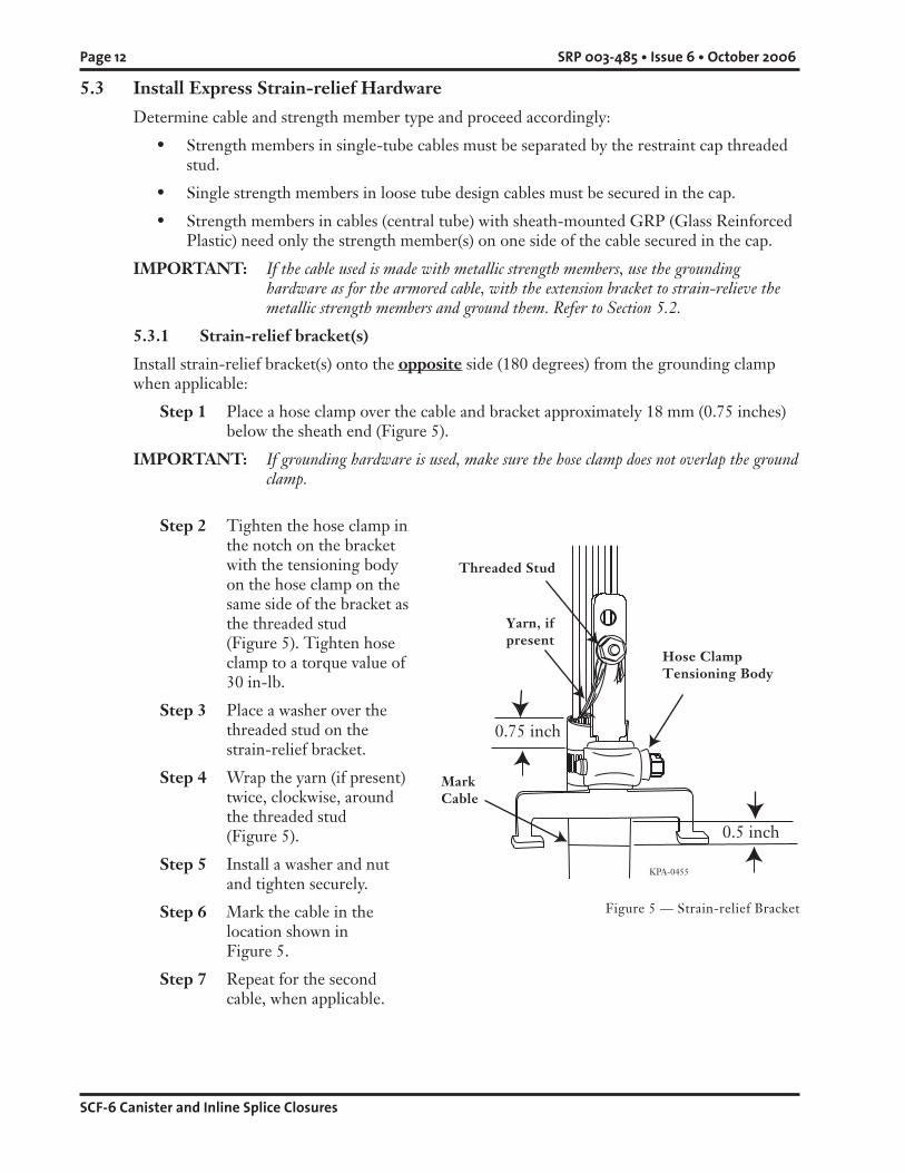
5.3.1 Strain-relief bracket(s)
Install strain-relief bracket(s) onto the opposite side (180 degrees) from the grounding clampwhen applicable:
Step 1 Place a hose clamp over the cable and bracket approximately 18 mm (0.75 inches)below the sheath end (Figure 5).
IMPORTANT: If grounding hardware is used, make sure the hose clamp does not overlap the groundclamp.
Threaded Stud
Yarn, ifpresent
Hose ClampTensioning Body
MarkCable
Step 2 Tighten the hose clamp inthe notch on the bracketwith the tensioning bodyon the hose clamp on thesame side of the bracket asthe threaded stud(Figure 5). Tighten hoseclamp to a torque value of30 in-lb.
Step 3 Place a washer over thethreaded stud on thestrain-relief bracket.
Step 4 Wrap the yarn (if present)twice, clockwise, aroundthe threaded stud(Figure 5).
Step 5 Install a washer and nutand tighten securely.
Step 6 Mark the cable in thelocation shown inFigure 5.
Step 7 Repeat for the secondcable, when applicable.

SRP 003-485 • Issue 6 • October 2006 Page 13
SCF-6 Canister and Inline Splice Closures
5.3.2 Nonmetallic strength member
If strength member is nonmetallic:
Step 1 Trim the strength memberflush with the top of thestrain-relief bracket.
Step 2 Insert the restraint capthreaded stud through thehole in the strain-reliefbracket capturing thestrength member between thetwo.
Step 3 With the nonmetallicstrength member behind thebracket, install a nut on therestraint cap threaded stud(Figure 6).
Step 4 Confirm buffer tubes areclear of the strengthelements. Tighten nutsecurely.
Step 5 Repeat for the second cable,when applicable.
Figure 6 — Strength Member Strain-relief
KPA-0380
Metallic Strength Members
Restraint Cap
StrengthMember
5.3.3 Metallic strength members
If strength members are metallic:
Step 1 Bend them over the slots in theextension bracket as shown in theinset in Figure 7 and then trimexcess strength member.
KPA-0513
Figure 7 — Metallic Strength Member Strain-relief

SCF-6 Canister and Inline Splice Closures
Page 14 SRP 003-485 • Issue 6 • October 2006
KPA-0382
KPA-0381
KPA-0456
Step 2 Wrap the yarn, ifpresent, twice in aclockwise directionaround the restraintcap threaded stud.
Step 3 Install restraint cap asshown in Figure 8.
Step 4 Install a washer andnut and tightensecurely.
Step 5 Repeat for othercables, whenapplicable.
IMPORTANT: Confirm allbuffer tubes areclear of thestrength elementsprior to securingthe restraint cap.
5.3.4 Large strength members
For cables with large strength members,use the large central member strian-reliefkit (p/n SCF-MBR-CMS, purchasedseparately) instead of the restraint caps(Figure 9):
Step 1 Slide the metal barrel overthe end of the centralmember.
Step 2 Align the threads in the sideof the barrel with the hole inthe top of the strain-reliefbracket.
Step 3 Install the supplied screwthrough the threaded hole inthe barrel.
Step 4 Tighten the screw.
Step 5 Trim the strength memberflush with the top of thestrain-relief bracket.
RestraintCap
Yarn, ifpresent
Figure 8 — Metallic Strength Member Strain-relief
Figure 9 — Large Strength Member Strain-relief

SRP 003-485 • Issue 6 • October 2006 Page 15
SCF-6 Canister and Inline Splice Closures
Figure 12 — End Cap Standoffs
5.4 Install Cable into the End Cap Express Ports
NOTE: Use the two main cable ports in the center of theend cap first (Figure 10). Use the drop ports asneeded.
5.4.1 Prepare the end cap
Step 1 Remove the frame from the end cap.
Step 2 Pull the end cap halves apart.
IMPORTANT: Do not use power tools to separate theend caps.
Express Ports
Figure 10 — Express Ports
Figure 11 — Holding Bracket
NOTE: A table bracket to stabilize the end capwhile installing and routing fiber isincluded with the inline closure only(Figure 11). The table bracket(p/n SCF-INST-BKT6) can bepurchased separately. Secure the endcap to the bracket using the providedtwo screws. Then secure the bracket tothe work surface using another screw(not provided).
Step 3 Beginning with the inside of theend cap, apply sealing tape to theend cap half containing the metallicstandoffs (Figure 12). Cut holes inthe tape to expose the standoffs.
IMPORTANT: It is imperative that the strain-relief bracket have no contactwith the tape. Make sure thestrain-relief tracks on the insideof the end cap and the screwholes are not obstructed by thesealing tape.
KPA-0502
KPA-0514
KPA-0515

SCF-6 Canister and Inline Splice Closures
Page 16 SRP 003-485 • Issue 6 • October 2006
5.4.2 Apply sealing tape to the cable
CAUTION: Isopropyl alcohol is flammable with a flashpoint at 54° F. It can causeirritation to eyes on contact. In case of eye contact, flush eyes with water for at least 15minutes. Inhaling fumes may induce mild dizziness. In case of ingestion, consult aphysician.
DICHTPASTE
0.5 in.
KPA-0458
Figure 13 — Apply Sealing Paste
CAUTION: Use sealing paste and cablecleaner in a well-ventilated area to eliminate thepossibility of dizziness and nausea. If paste orcleaner comes in contact with skin or eyes, washarea immediately with soap and water to avoidirritation. Do not induce vomiting if pastecleaner is ingested.
Step 1 Clean the cable where the tape will be appliedusing the provided alcohol pad.
Step 2 Beginning at the mark shown in Figure 13,use wax-paper backing from the sealing tapeto spread the “dichtpaste” sealing paste evenlyaround the cable in the area where the sealingtape will be applied. Allow the sealing paste todry.
A B
Figure 14 — Sealing Tape
Step 3 Cut and pull the strip ofsealing tape as shown inFigure 14. The tape willstretch and thin before itbreaks.
Step 4 Starting at the markshown in Figure 13, wrapthe tape around the cableuntil it fills the diameter“C” on the end capgauge tool (Figure 15A).Express ports willaccommodate cable witha maximum diameter of25 mm (1.0 inch); somecables require only onewrap of sealing tape toreach this diameter.Always finish with acomplete wrap thatoverlaps the startingpoint by approximately0.5 inch (Figure 15B).
10 mm (.25 in.)
KPA-190
KPA-0194
C
KPA-0449
NOTE: The end cap gauge tool is used in several steps during the assembly process. Use only this tool formeasuring and tightening components where indicated (Table 1).
0.5 in.
Figure 15 — Measure Sealing Tape Around Cable

SRP 003-485 • Issue 6 • October 2006 Page 17
SCF-6 Canister and Inline Splice Closures
Figure 16 — Dummy Plug
Step 5 Repeat Section 5.4.1 and 5.4.2 for the other cable to be installed in the expressport, if applicable.
5.4.3 Use a dummy plug
When the closure only has one cable installed in eitherend cap, use a dummy plug (p/n SCF-4-6-PLUG,purchased separately) to fill the unused port.
Step 1 If using a dummy plug follow instructionsin Section 5.4.2 to install sealing paste andtape to dummy plug.
Step 2 Install dummy plug with the closed end ofthe plug flush against the outside of theend cap (Figure 16).
5.4.4 Install cable
Step 1 Wrap hose clamps and restraint caps with vinyl tape to prevent the sharp edgesfrom damaging the fiber.
Step 2 Place one side of the express cable sheath in the express port on the untaped endcap half by inserting the strain-relief bracket in the tracks.
Step 3 Place the other side of the express cable sheath on the taped end cap half(Figure 17) in the center express port by inserting the strain-relief bracket in thetracks.
Figure 17 — Install Cable into End Cap
Strain-relief Tracks
SealingRing
Channel
SealingRing
Channel
Vinyl Tape
Dummy Plug
KPA-0447
KPA-0503

SCF-6 Canister and Inline Splice Closures
Page 18 SRP 003-485 • Issue 6 • October 2006
KPA-0504
Location forLong Bolts
Locationfor
ShortBolt
Figure 18 — Close End Cap Halves
5.4.5 Close end cap halves
IMPORTANT: Do not use power tools to tighten the end cap.Step 1 Place the upper end cap half
over the lower end cap half.
Step 2 Install one short bolt andwasher on each side of theend cap half.
Step 3 Install two long bolts andwashers.
Step 4 Alternately tighten the boltsto close the end cap(Figure 18).
IMPORTANT: While tightening, ensurethat the feet of the strain-relief bracket remaininside the tracks. Do notuse power tools to tighten.
Step 5 Tighten the bolts until the end cap closing gauge tool (Section H) fits over thesides and center measuring points of the end cap (Figure 19).
Step 6 Cut excess sealing tape from the sealing ring channel and strain-relief tracks(shown by dashed circles in Figure 17) using scissors or side cutters.
NOTE: Do not pull or stretch sealing tape.
Step 7 Completely remove any remaining sealing tape inside the sealing ring channel withthe blade of a screwdriver.
Figure 19 — Tighten End Cap
H
H
H
H
KPA-0540

SRP 003-485 • Issue 6 • October 2006 Page 19
SCF-6 Canister and Inline Splice Closures
5.6 Prepare Drop Cable Port(s)
Step 1 Choose a cable port to be used and open the port using a hacksaw or a knife(Figure 21). Be careful not to damage the internal threads of the drop port whilesawing.
IMPORTANT: Use either or both of the middle ports on the end cap first to make routing easier.
Step 2 Smooth the port opening using a cable knife as shown in Figure 22.
VentedGroundingScrew
Figure 21 — Open Drop Port
5.4.6 Install vented grounding screw
Step 1 Apply a thin coat of UCN lubricant to the threads of the vented grounding screw.
Step 2 Install the vented grounding screw in the threaded insert on the inside of the endcap finger-tight plus one half turn (approximately 40 to 60 in-lb).
5.5 Ground Armored Cable
Ground armored cable per local practices.
Figure 20 — Ground End Cap
Figure 22 — Smooth Port Opening
Step 1 Remove the small insertfrom the grounding screwand install a grounding wire.Tighten the insert.
Step 2 Secure the other end of thisgrounding wire to theground clamp post of one ofthe main cables in theexpress ports.
Step 3 Attach one end of a secondgrounding wire to thisground clamp post.
Step 4 Attach the opposite end ofthe second wire to thesecond expressed cable(Figure 20).
KPA-0539
KPA-0506
KPA-0507

SCF-6 Canister and Inline Splice Closures
Page 20 SRP 003-485 • Issue 6 • October 2006
Refer to SRP 206-286 (Mechanical End Cap Canister Closure Sealing Checklist) to ensure allcritical steps in Sections 5.4 and 5.7 for sealing the closure have been performed accurately.
Figure 23 — Sealing Grommet Size Table 2 — Cable Diameter
Figure 24 — Washer Orientation
Step 3 Place the end cap gauge to determine which size sealing grommet is required(Figure 23 and Table 2).
Step 4 Place a toothed washer onto thesealing grommet and insertboth into the opened port fromthe strain-relief side of the endcap (Figure 24). Verify correctplacement of toothed washer ongrommet.
Figure 25 — Lock Nut
Figure 26 — Compression Screw
Sealing Grommet
Toothed Washer
KPA-0468
5.7 Install Drop Port Cable into End Cap
Step 1 Secure the sealing grommet andtoothed washer with the locknut on the inside of the end cap.
Step 2 Use the end cap gauge totighten the nut until it stops andis tight (Figure 25).
Step 3 Slide the compression screwover the cable.
Step 4 Slide the cable through the port(Figure 26).
A
A
KPA-0469
KPA-0470
CableCable
D
CableCable
D
KPA-0508
Greater thanor equal to: Less than:
18 mm AND Large
AND Medium
AND Small5 mm
NOTE: Dimensions are for reference only. Use SCF6 combination wrench to determine cable size.
CableDiameter
Range:
If Cable Diameter Is:
Cable is too small for sealing system.
SelectGrommet
SizeWrench Gauge
"D"
Wrench Gauge"E"
Wrench Gauge"K"
Less than "K"
Wrench Gauge"F"
Wrench Gauge"D"
Wrench Gauge"E"
FlatRequires p/n SCF-KT-G84-F Grommet kit (purchased separately)
KPA-0509

SRP 003-485 • Issue 6 • October 2006 Page 21
SCF-6 Canister and Inline Splice Closures
0.75 inch
KPA-0471
Threaded Stud
YarnBracket
Hose ClampTensioning Body
MountingScrew
Restraint Cap
Figure 27 — Drop Strain-relief Bracket
Step 5 Prepare cable per Section 5.1. If the cable is armored, attach groundinghardware as shown in Figure 4.
IMPORTANT: If the cable used is made with metallic strength members, use the groundingconnector as for the armored cable, with the extension bracket to strain-relieve thestrength member and ground it. Refer to Sections 5.2 and 5.3.
5.8 Strain-relieve Drop Port Cables
If installing SST-Drop™ cables in drop ports, refer to the instruction provided with thestrain-relief kit (p/n SCF-KT-G84-F, purchased separately) for detailed instructions for strain-relieving the drop cables.
Install a drop port strain-relief bracket onto each drop port cable on the opposite side of thecable (180 degrees) from the ground clamp when applicable:
Step 1 Pull the cable approximately 12 inches away from the end cap to ease bracketinstallation.
IMPORTANT: Secure the cable to the side of the bracket opposite the threaded stud.
Step 2 Place a hose clamp over the cable and bracket 18 mm (0.75 inch) below thesheath end.
IMPORTANT: If grounding hardware is used, make sure the hose clamp does not overlap theground clamp.
Step 3 Tighten the hose clamp in the notch on the bracket with the tensioning body onthe hose clamp on the same side of the bracket as the threaded stud (Figure 27).Tighten hose clamp to a torque value of 30 in-lb.
IMPORTANT: Tighten hose clamp on SST-Drop cables to a torque value of 20 in-lb.
Step 4 Trim nonmetallic strength member flush with the top of the bracket.
Step 5 Insert the restraint cap threaded stud through the hole in the strain-reliefbracket, capturing the central strength member between the two (Figure 27).
Step 6 Install a washer and nut onto the restraint cap stud and tighten securely.Step 7 Wrap the aramid yarn, if
present, twice in aclockwise direction aroundthe threaded stud on thebracket (Figure 27).
Step 8 Install a second washer andnut and tighten securely.
IMPORTANT: Ensure that all buffertubes are cleared frombeneath the strengthmember prior totightening the restraintcap.
Step 9 Wrap hose clamp andrestraint cap with vinyltape to prevent the sharpedges from damaging thefiber.

SCF-6 Canister and Inline Splice Closures
Page 22 SRP 003-485 • Issue 6 • October 2006
5.9 Complete Frame Assembly
Reattach the frame assembly to the end cap.
5.10 Attach Strain-relief Bracket
Attach the strain-relief bracket to the frame:
Step 1 Pull the cable back to the endcap.
Step 2 Center the cable over the portand slide the attached screw onthe strain-relief bracket into theslot on the metal frame.
Step 3 Tighten the strain-relief bracketmounting screw (Figure 28).
Step 4 Repeat Section 5.6 throughSection 5.8 for all drop cables.
Refer to SRP 206-286 (Mechanical End Cap Canister Closure Sealing Checklist) to ensure allcritical steps in Section 5.11 for sealing the closure have been performed accurately.
Figure 28 — Install onto Frame
Vinyl Tape
5.11 Tighten End Cap Compression Screw
Secure compression screw into end cap.Tighten with the end cap gauge until theclicking sound stops or the screw is buttedagainst the end cap (Figure 29).
IMPORTANT: DO NOT overtighten thescrew.
Figure 29 — Tighten Compression Screw
5.12 Splice
5.12.1 Prepare fiber for splicing
Step 1 Place an empty splice trayinto the stacker assemblywith the tray buttedagainst the fibermanagement assembly(Figure 30). Figure 30 — Empty Splice Tray
KPA-0474
KPA-0510
HD
E G
KPA-0473

SRP 003-485 • Issue 6 • October 2006 Page 23
SCF-6 Canister and Inline Splice Closures
Step 2 Select the buffer tubes to be splicedin this splice tray and route the buffertube(s) past the rear of the splice traystacker.
Step 3 Curve past the inside of the adjusterbracket and place the buffer tube(s)next to the corner of the splice tray.
Step 4 Use a permanent marker to mark thebuffer tube 19 mm (0.75 in.) from thecorner of the splice tray (Figure 31).
Step 5 Remove the buffer tube in 30 cm(12-inch) increments until reachingthe mark made in the previous step.
Step 6 Clean fibers according to cablemanufacturer’s instructions.
Step 7 Secure the buffer tube to the tray perinstructions provided with the splicetray.
Step 8 Prepare any other splice trays thesame way.
Step 9 When all trays are prepared, spliceper local practice.
5.12.2 Store cable slack
Loop any unspliced (or express) buffer tubes insidethe slack basket (Figure 32).
Figure 31— Mark the Buffer Tube
Figure 32 — Loop Unspliced Buffer Tubes
KPA-0475
In-Line (SCF-6T)Canister (SCF-6C)
Figure 33 — Secure Spliced Trays
KPA-0476
KPA-0477
19 mm
KPA-0537
5.12.3 Secure spliced trays
Step 1 Place the spliced trays into the tray stacker. Make sure the buffer tubes are withinthe flange on the tray stacker as shown (Figure 33).
Step 2 Secure the buffer tubes using cable ties as needed.

SCF-6 Canister and Inline Splice Closures
Page 24 SRP 003-485 • Issue 6 • October 2006
Proceed to Section 5.13 to seal an inline closure.Proceed to Section 5.14 to seal a canister closure.
5.13 Seal the Inline Closure
NOTE: Do not use encapsulant in SCF closures.
4.13.1 Install sealing gasket
Step 1 Verify there is no sealing tape in the sealing ring channel. Flatten any sealing tapewith the blade of a screwdriver.
Step 2 Use the supplied brush to apply UCN lubricant to the sealing ring channel on theend cap (Figure 36).
Step 3 Apply a thin coat of UCN lubricant to the mating surfaces of the end cap gasket.Insert the bottom part of the sealing gasket clip into the hole in the sealing ring(Figure 37).
Step 3 Store the end cap gaugebetween the splice traystacker and the frame(Figure 34).
Step 4 Secure all buffer tubes,splice trays and thecombination wrenchusing the hook-and-loopstraps.
IMPORTANT: Position the wrenchso that it does notinterfere with thedome cover duringinstallation.
Step 5 Reposition the adjusterbracket to keep the traysfrom moving, ifnecessary(Figure 35).
Figure 35 — Adjuster Bracket
Figure 34 — Store End Cap GaugeKPA-0478
EndCapGauge
Straps
AdjusterBracket
KPA-0538
LUBBRIICANNTT
KPA-0479
Figure 36 — Lubricate Channel Figure 37 — SCF Gasket Clip
KPA-0649
Top
Bottom

SRP 003-485 • Issue 6 • October 2006 Page 25
SCF-6 Canister and Inline Splice Closures
Figure 39 — End View of Gasket Orientation
Figure 40 — Lubricate Gasket
Step 4 Push the joiner clip together untilboth parts of the clip latch. The clipmust snap audibly before it is secure.Tension the sealing gasket slightly atthe closing point to make sure thatboth ends of the gasket are properlyaligned (Figure 38).
Figure 38 — Gasket Profile
Step 5 Place the sealing gasket into the endcap channel. Make sure the clip isalways on top of the sealing gasket(Figure 39).
IMPORTANT: Position the clip on the gasketaway from the seam where theend cap halves are joined togetheras shown in Figure 39. Insert thejoining point of the sealing ringfirst and hold tight so that notension is applied to this area.
Step 6 Apply one third tube oflubricant to the top of the endcap gasket (Figure 40).
Step 7 Repeat steps in section 5.12.1for the end cap at the other endof the closure.
KPA-0482
KPA-0650
KPA-0651
Clip
Clamping Bar
End Cap

SCF-6 Canister and Inline Splice Closures
Page 26 SRP 003-485 • Issue 6 • October 2006
5.13.2 Prepare closure cover
Step 1 Remove the red protection clips fromthe closure cover and throw themaway (Figure 41).
Step 2 Apply one third tube of lubricantalong the gasket channel in theclosure cover (Figure 42).
KPA-0483
Figure 41 — Remove Clip from Cover
KPA-0486
Step 3 Install the cover gasket with the gasket notches inserted in the keys at the end ofthe closure cover. Begin at the center of the cover and work towards both ends.
IMPORTANT: Note that the cover gasket is longer than the channel. This is a design feature formaximum performance. DO NOT CUT THE GASKET.
Step 4 Retain a small amount of lubricant for use later. Cover the gasket with theremaining lubricant (Figure 43).
Figure 42 — Lubricate Gasket Channel Figure 43 — Lubricate Cover Gasket
KPA-0485KPA-0484
5.13.3 Install closure cover
Step 1 Center the cover over the endcaps with the key on the covergasket opposite the clip on theend cap gaskets (Figure 44).Make sure the end caps are insidethe end cap stops on each end ofthe closure cover.
IMPORTANT: Make sure that the clip on theend cap gasket is not positionedon the seam of the end capsand is on the opposite side ofthe end cap from the covergasket.
Figure 44 — Install Inline Cover
Key on Cover Gasket

SRP 003-485 • Issue 6 • October 2006 Page 27
SCF-6 Canister and Inline Splice Closures
Step 2 Pop the clamping bar locks out of the inserts.
Step 3 Place the clamping bars on the closure cover as shown in Figure 45.
Step 5 Tap lightly in a downwarddirection to set the clampingbar locks (Figure 47).
Refer to SRP 206-287 (Mechanical End Cap Inline Closure Sealing Checklist) to ensure allcritical steps in Section 5.13 for sealing the closure have been performed accurately.
Figure 45 — Install Clamping Bars
KPA-0488
Figure 46 — Hammer Clamping Bars
Figure 47 — Hammer LocksKPA-0489
Step 4 Close the clamping bars by tapping alternately with a hammer.
IMPORTANT: DO NOT hammer directly on the clamping bars; this will damage them. Place ablock of wood over the clamping bars and tap lightly with a hammer (Figure 46).When the clamping bars are completely closed, a 0.28-inch gap will remain betweenthe bars and the clamping bar locks will align with the holes in the cover.
KPA-0487
Bar Locks
Clamping Bars
KPA-0493

SCF-6 Canister and Inline Splice Closures
Page 28 SRP 003-485 • Issue 6 • October 2006
Step 2 Verify there is no sealing tape inthe sealing ring channel.Flatten any sealing tape with aflat-tipped screwdriver.
Step 3 Use the supplied brush to applya third of the UCN lubricanttube to the sealing ring channelon the end cap (Figure 49).
5.14 Seal the Canister Closure
NOTE: Do not use liquid encapsulant in SCF closures.
5.14.1 Install seal
Step 1 Roll the sealing ring over frame (Figure 48)and down to the end cap with arrows asshown.
IMPORTANT: The sealing ring must be installed in theorientation shown.
KPA-0490
Figure 48 — Sealing Ring
LUBBRIICANN
TT
KPA-0479
Figure 49 — Lubricate Sealing Ring Channel
Step 4 Stretch the sealing ring over the channel (Figure 50).
Step 5 Fold the edge of the seal that overlaps the outside of the end cap until the seal seatsin the channel as shown in Figure 51.
IMPORTANT: The installed sealing ring must be oriented as shown toward the inside of the closure(Figure 51).
KPA-0491 KPA-0293
Figure 50 — Install Sealing Ring Figure 51 — Fold Sealing Ring

SRP 003-485 • Issue 6 • October 2006 Page 29
SCF-6 Canister and Inline Splice Closures
RXS
KPA-0542
RXS
KPA-0541
Step 6 Retain a small amount of UCNlubricant for use later. Apply theremaining lubricant to all sides of thesealing ring (Figure 52).
5.14.2 Install the canister cover
Step 1 Slide the canister over the closureassembly (Figure 53).
Step 2 Loosen both bolts on the clampingring.
Step 3 Apply a thin coat of UCN lubricantretained previously to the threads ofthe clamping ring latch bolts toprevent the bolts from seizing onreentry.
Step 4 Place the clamping ring over theflange of the canister and the sealingring with the embossed letteringtoward the outside of the closure.Ensure that both the sealing ring andthe canister flange are within theclamping ring (Figure 54).
NOTE: The clamping ring seams must be oriented90-degrees from the end cap seam(Figure 54).
Step 5 Swing the clamping ring into closingposition. Tighten the bolts until theplastic on the ring touches, thentorque to a 50 in-lb value(Figure 55).
IMPORTANT: A torque value of 50 in-lb shouldbe sufficient. Do not use powertools to tighten the clamping ring;a torque value of more than 80in-lb causes the hardware to crackand the clamping ring to becomedefective. If the clamping ringdoes not close properly, make surethe sealing ring and clampingring are oriented correctly.
Figure 52 — Lubricate Sealing Ring
LUBBRRICANNT
KPA-0294
KPA-0492
Figure 53 — Slide Dome
Figure 54 — Clamping Ring
Figure 55 — Tighten Clamping Ring
90-degrees

SCF-6 Canister and Inline Splice Closures
Page 30 SRP 003-485 • Issue 6 • October 2006
KPA-0296
5.15 Install a Flash Test Air Valve
5.15.1 Install valve stem
Step 1 Apply a thin coat of UCN lubricantretained previously to the threads of thevalve stem (p/n UCN-KT-FV, packageof five, purchased separately).
Step 2 Install the valve stem finger-tight, thenanother half turn with a wrench, intothe grounding port as shown inFigure 56.
5.15.2 Perform flash test
Step 1 Inject 12 to 14 psi of air into the closureusing a hand pump (Figure 57). Checkpressure regularly.
WARNING: To avoid a potentiallyhazardous situation that could result indeath or serious injury, do not exceed 14psi (100 kpa) gauge pressure. The closurecould burst.
Step 2 Apply soapy water to the seal points andwatch closure for signs of leakage(bubbling of soap). A correctly sealedclosure maintains pressure with noleaks.
KPA-0295
Figure 56 — Valve Stem
Figure 57 —Pressurize Closure
KPA-0297
KPA-0289
Figure 58 — Ground Screw
Figure 59 — Ground Wire
Step 3 After the flash test has been performed andthe closure sealed correctly, carefully releasepressure, remove the air valve and allow air toescape.
Step 4 Apply a thin coat of UCN lubricant retainedpreviously to the threads of a solid, two-piecenonvented grounding screw (Figure 58).
Step 5 Install the screw into the end cap from theoutside of the end cap finger-tight, thenanother half turn (approximately 40 to60 in-lb).
5.16 Ground the Closure
Step 1 Remove the smaller insert from the groundingscrew.
Step 2 Connect a grounding cable (not supplied) tothe screw (Figure 59).
Step 3 Screw the smaller insert back into the screw.
Step 4 Tighten the insert using a small adjustablewrench.
Step 5 Terminate the other end of the ground perlocal practices.

SRP 003-485 • Issue 6 • October 2006 Page 31
SCF-6 Canister and Inline Splice Closures
KPA-0493
Refer to SRP 206-286 (Mechanical End Cap Canister Closure Sealing Checklist) to ensure allcritical steps in Section 5.14 and 5.15 for sealing the closure have been performed accurately.
5.17 Reenter the Inline Closure
Step 1 If it is necessary to reenter the inline closure, verify there is no pressure byremoving external ground screw and allowing air to escape.
Step 2 Remove clamping bars. Pry upwards with a flat-tip screwdriver to open theclamping bar locks (Figure 60). Alternately tap against the stop on the top of thebars (Figure 61).
KPA-0494
Step 3 Perform any tests, modifications, or examinations of the closure that are necessary.
Step 4 Reinstall the clamping bars per Section 5.12.3.
Step 5 Flash test closure per Section 5.14 on every entry.
Step 6 Reterminate ground, if applicable, per Section 5.15.
5.18 Reenter the Canister Closure
Step 1 If it is necessary to reenter the canister closure, verify there is no pressure byremoving external ground screw and allowing air to escape.
Step 2 Remove clamping ring by untightening the two bolts.
Step 3 Perform any tests, modifications or examinations of the closure that are necessary.
Step 4 Reinstall the clamping ring per Section 5.13.2.
Step 5 Flash test closure per Section 5.14 on every entry.
Step 6 Reterminate ground, if applicable, per Section 5.15.
Figure 60 — Pry Locks Open Figure 61 — Hammer Clamping Bars Off

Page 32 SRP 003-485 • Issue 6 • October 2006
KPA-0680
Corning Cable Systems reserves the right to improve, enhance and modify the features andspecifications of Corning Cable Systems’ products without prior notification. ALTOS is aregistered trademark of Corning Cable Systems Brands, Inc. SST-Drop is a trademark ofCorning Cable Systems Brands, Inc. All other trademarks are the properties of their respectiveowners. Corning Cable Systems is ISO 9001 certified.© 1999-2002, 2005-2006 Corning Cable Systems. All rights reserved. Published in the USA.p/n 003-485 / October 2006
Customer Service—US or Canada: 1-800-743-2671International: +1-828-901-5000Fax: +1-828-325-5060Corning Cable Systems LLC, PO Box 489,Hickory, NC 28603-0489 USAhttp://www.corning.com/cablesystems
Long Bolts
ShortBolt
5.19 Reopen the End Cap
Step 1 Reenter the closure as describedin Section 5.16 for inline closuresor Section 5.17 for canisterclosures.
Step 2 Separate the frame from the endcaps by removing the two screws.
Step 3 Remove the end cap sealing ring.
Step 4 Remove the two long boltsholding the end cap segmentstogether (Figure 62).
Step 5 Insert a flat screwdriver in the square opening on either side of the end cap to helppry open the end cap segments (Figure 63).
Step 6 Remove any sealing tape from inside the square opening on either side of the endcap where the bolt will be inserted to prevent the threads of the bolt frombecoming clogged.
Step 7 Insert one of the long bolts into either hole that has a threaded insert (next to theouter closing holes) as shown in Figure 64.
Step 8 Tighten the long bolts on either side of the end cap while holding the screwdriverin place.
Step 9 Alternate tightening the bolts until the end cap halves are fully separated.
IMPORTANT: Do not use power tools to separate the end caps.
KPA-0496 KPA-0497
Figure 62 — Reopen End Cap
Figure 63 — Insert Screwdriver Figure 64 — Tighten Bolts