Embed Size (px)
Citation preview

Scheduled/Special Inspections & Recommended
Support Parts
MEGA CORP.®
700 Osuna Rd. N.E. • Albuquerque, NM 87113 • 1-800-345-8889 • 505-345-2661 • Fax 505-345-6190www.megacorpinc.com
® 2011 MEGA Corp., Inc. All Rights Reserved
SPECIALTY HAULAGE SOLUTIONS FOR MINING AND CONSTRUCTION
MTT20-KOM785(7) -05

MTT20-KOM785(7)-5 14 Apr 2011
TABLE OF CONTENTS
A
Page Section 1. Definitions and Abbreviations …………………………………………………… 1-1 Section 2. Scheduled Inspections …………………………………………………………… 2-1
Section 3. Special Inspections ………………………………………………………………. 3-1 Section 4. Recommended Support Parts ……………………………………………………. 4-1
MTT20-KOM785(7)-5 14 Apr 2011
TABLE OF CONTENTS
B(Blank)
MTT20-KOM785(7)-5 14 Apr 2011
SECTION 1 Definitions & Abbreviations
Contents
1-1
Manual Usage ........................................ 1-1 Warnings, Cautions and Notes …........... 1-1 Shall and Will, Should, and May ….….. 1-1
Safety Messages ……………...…..…. 1-1 Abbreviations ……..………….…..…. 1-4 Overview ……………………….…… 1-5
MANUAL USAGE This Technical Manual only contains information required to safely maintain the MEGA water system when installed on the KOMATSU 785-7 Only current production systems are covered in this manual. If your system is not covered in this manual please contact MEGA Corp. Product Support at: 1-800-345-8889 or visit our web site at www.megacorpinc.com for more detailed information. See the KOMATSU 785-7 specific Operation & Maintenance, Safety Manuals and Service Manuals for detailed chassis specific system information and chassis specific maintenance procedures. WARNINGS, CAUTIONS AND
NOTES
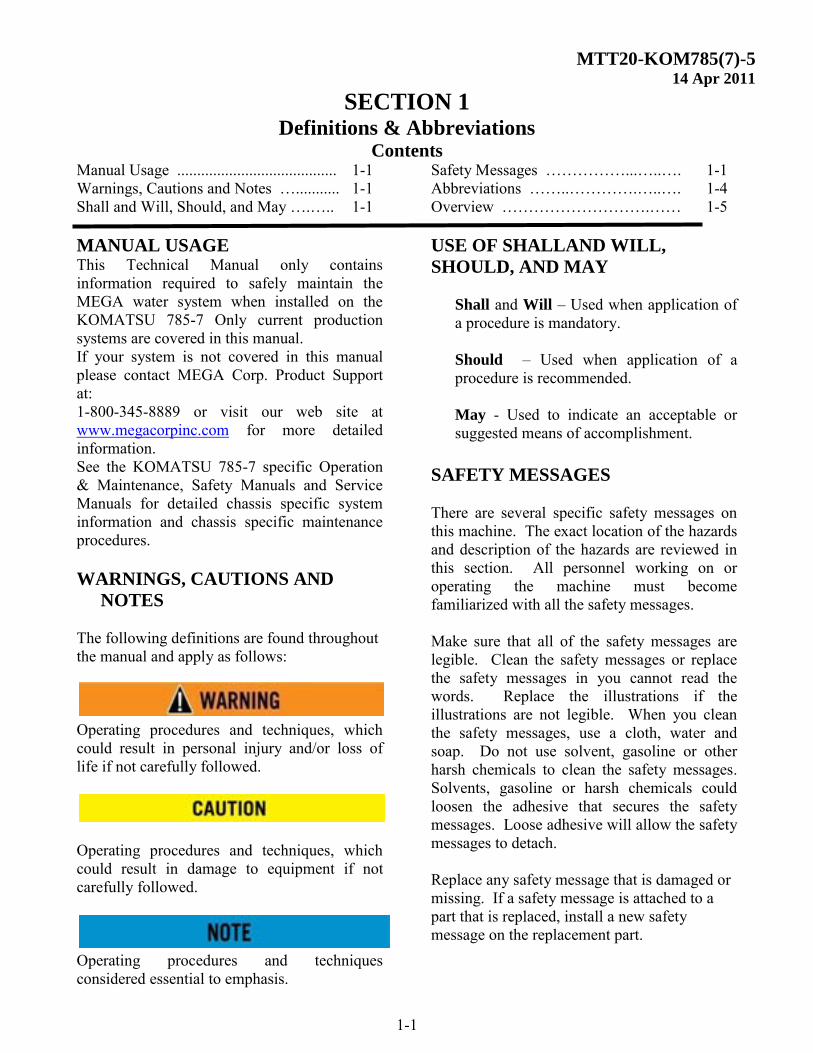
The following definitions are found throughout the manual and apply as follows: Operating procedures and techniques, which could result in personal injury and/or loss of life if not carefully followed.
Operating procedures and techniques, which could result in damage to equipment if not carefully followed. Operating procedures and techniques considered essential to emphasis.
USE OF SHALLAND WILL,
SHOULD, AND MAY Shall and Will – Used when application of a procedure is mandatory. Should – Used when application of a procedure is recommended. May - Used to indicate an acceptable or suggested means of accomplishment.
SAFETY MESSAGES There are several specific safety messages on this machine. The exact location of the hazards and description of the hazards are reviewed in this section. All personnel working on or operating the machine must become familiarized with all the safety messages. Make sure that all of the safety messages are legible. Clean the safety messages or replace the safety messages in you cannot read the words. Replace the illustrations if the illustrations are not legible. When you clean the safety messages, use a cloth, water and soap. Do not use solvent, gasoline or other harsh chemicals to clean the safety messages. Solvents, gasoline or harsh chemicals could loosen the adhesive that secures the safety messages. Loose adhesive will allow the safety messages to detach. Replace any safety message that is damaged or missing. If a safety message is attached to a part that is replaced, install a new safety message on the replacement part.
MTT20-KOM785(7)-5 14 Apr 2011
SECTION 1 Definitions and Abbreviations
1-2
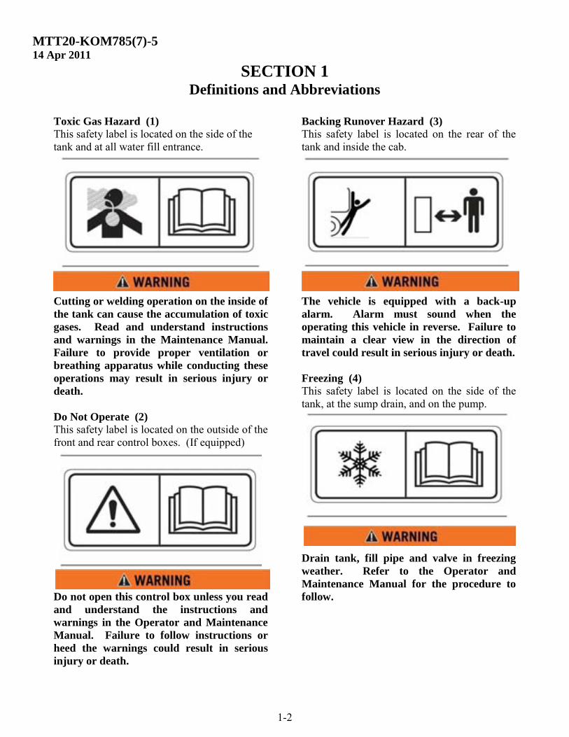
Toxic Gas Hazard (1) This safety label is located on the side of the tank and at all water fill entrance.
Cutting or welding operation on the inside of
the tank can cause the accumulation of toxic
gases. Read and understand instructions
and warnings in the Maintenance Manual.
Failure to provide proper ventilation or
breathing apparatus while conducting these
operations may result in serious injury or
death.
Do Not Operate (2)
This safety label is located on the outside of the front and rear control boxes. (If equipped)
Do not open this control box unless you read
and understand the instructions and
warnings in the Operator and Maintenance
Manual. Failure to follow instructions or
heed the warnings could result in serious
injury or death.
Backing Runover Hazard (3)
This safety label is located on the rear of the tank and inside the cab. The vehicle is equipped with a back-up
alarm. Alarm must sound when the
operating this vehicle in reverse. Failure to
maintain a clear view in the direction of
travel could result in serious injury or death.
Freezing (4)
This safety label is located on the side of the tank, at the sump drain, and on the pump. Drain tank, fill pipe and valve in freezing
weather. Refer to the Operator and
Maintenance Manual for the procedure to
follow.
MTT20-KOM785(7)-5 14 Apr 2011
SECTION 1 Definitions And Abbreviations
1-3
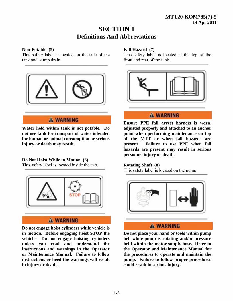
Non-Potable (5) This safety label is located on the side of the tank and sump drain. Water held within tank is not potable. Do
not use tank for transport of water intended
for human or animal consumption or serious
injury or death may result.
Do Not Hoist While in Motion (6)
This safety label is located inside the cab. Do not engage hoist cylinders while vehicle is
in motion. Before engaging hoist STOP the
vehicle. Do not engage hoisting cylinders
unless you read and understand the
instructions and warnings in the Operator
or Maintenance Manual. Failure to follow
instructions or heed the warnings will result
in injury or death.
Fall Hazard (7)
This safety label is located at the top of the front and rear of the tank. Ensure PPE fall arrest harness is worn,
adjusted properly and attached to an anchor
point when performing maintenance on top
of the MTT or when fall hazards are
present. Failure to use PPE when fall
hazards are present may result in serious
personnel injury or death.
Rotating Shaft (8)
This safety label is located on the pump. Do not place your hand or tools within pump
bell while pump is rotating and/or pressure
held within the motor supply hose. Refer to
the Operator and Maintenance Manual for
the procedures to operate and maintain the
pump. Failure to follow proper procedures
could result in serious injury.
MTT20-KOM785(7)-5 14 Apr 2011
SECTION 1 Definitions and Abbreviations
1-4
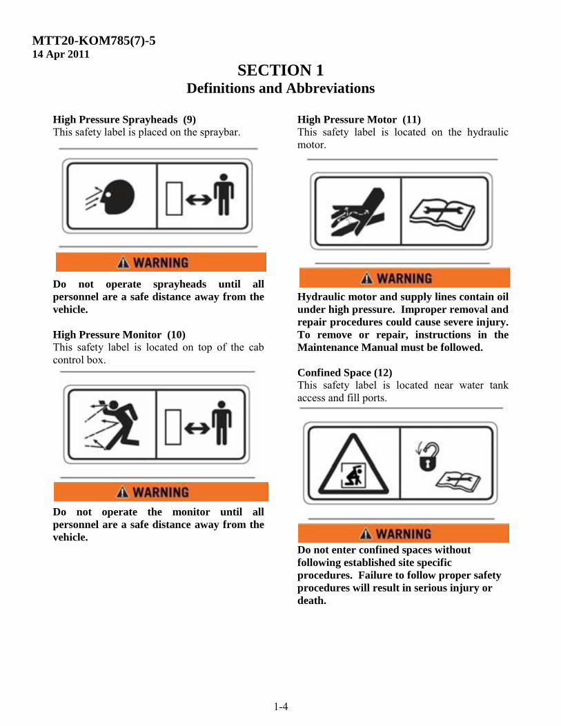
High Pressure Sprayheads (9)
This safety label is placed on the spraybar.
Do not operate sprayheads until all
personnel are a safe distance away from the
vehicle.
High Pressure Monitor (10)
This safety label is located on top of the cab control box. Do not operate the monitor until all
personnel are a safe distance away from the
vehicle.
High Pressure Motor (11)
This safety label is located on the hydraulic motor. Hydraulic motor and supply lines contain oil
under high pressure. Improper removal and
repair procedures could cause severe injury.
To remove or repair, instructions in the
Maintenance Manual must be followed.
Confined Space (12)
This safety label is located near water tank access and fill ports. Do not enter confined spaces without
following established site specific
procedures. Failure to follow proper safety
procedures will result in serious injury or
death.
MTT20-KOM785(7)-5 14 Apr 2011
SECTION 1 Definitions and Abbreviations
1-5
ABBREVIATIONS
BFV – Butterfly Valve CCW - Counterclockwise CW - Clockwise EPC – Electric Proportional Control FIP - Fault Isolation Procedures Ft-lbs – Foot Pounds of Torque GPM – Gallons per Minute IPB - Illustrated Parts Breakdown LT - Left (as viewed from the rear of the vehicle looking forward) MTT – MEGA Truck Tank n-m – Newton Meters of Torque PSI – Pounds per Square Inch QCA – Quick Change Assembly RT - Right (as viewed from the rear of the vehicle looking forward) RPM - Revolutions per minute VDC – Volts Direct Current
MTT20-KOM785(7)-5 14 Apr 2011
SECTION 1 Definitions and Abbreviations
1-6
``
SIDE
VIEW
REAR
VIEW
1
3 3
5
6
4
2
3
1
2
4
5
6
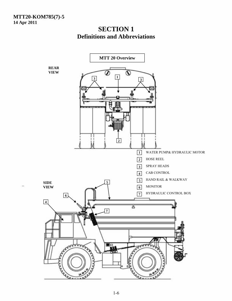
WATER PUMP& HYDRAULIC MOTOR
HOSE REEL SPRAY HEADS
CAB CONTROL HAND RAIL & WALKWAY
MONITOR
7 HYDRAULIC CONTROL BOX
7
MTT 20 Overview
MTT20-KOM785(7)-5 14 Apr 2011
SECTION 2 Scheduled Inspections
2-1
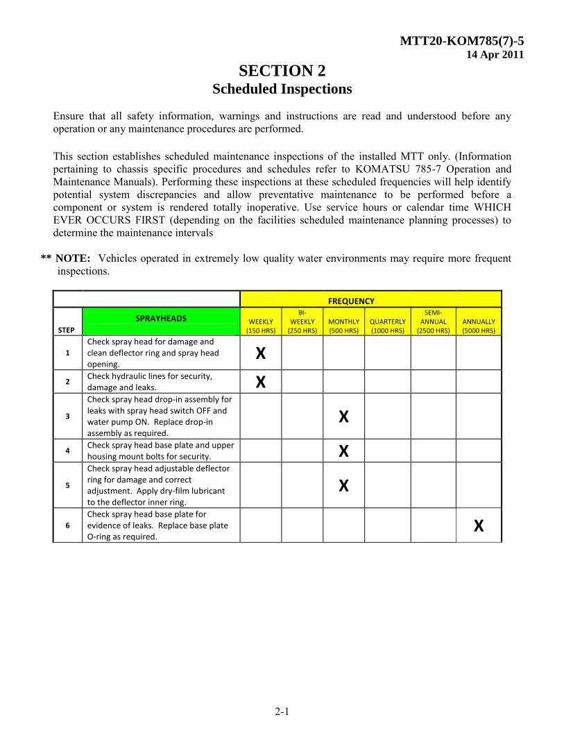
Ensure that all safety information, warnings and instructions are read and understood before any operation or any maintenance procedures are performed. This section establishes scheduled maintenance inspections of the installed MTT only. (Information pertaining to chassis specific procedures and schedules refer to KOMATSU 785-7 Operation and Maintenance Manuals). Performing these inspections at these scheduled frequencies will help identify potential system discrepancies and allow preventative maintenance to be performed before a component or system is rendered totally inoperative. Use service hours or calendar time WHICH EVER OCCURS FIRST (depending on the facilities scheduled maintenance planning processes) to determine the maintenance intervals
** NOTE: Vehicles operated in extremely low quality water environments may require more frequent inspections.
FREQUENCY
STEP
SPRAYHEADS
WEEKLY (150 HRS)
BI-WEEKLY
(250 HRS) MONTHLY (500 HRS)
QUARTERLY (1000 HRS)
SEMI-ANNUAL
(2500 HRS) ANNUALLY (5000 HRS)
1
Check spray head for damage and clean deflector ring and spray head opening.
X
2 Check hydraulic lines for security, damage and leaks. X
3
Check spray head drop-in assembly for leaks with spray head switch OFF and water pump ON. Replace drop-in assembly as required.
X
4 Check spray head base plate and upper housing mount bolts for security. X
5
Check spray head adjustable deflector ring for damage and correct adjustment. Apply dry-film lubricant to the deflector inner ring.
X
6
Check spray head base plate for evidence of leaks. Replace base plate O-ring as required.
X
MTT20-KOM785(7)-5 14 Apr 2011
SECTION 2 Scheduled Inspections
2-2
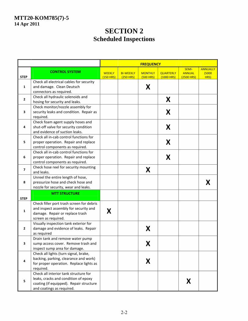
FREQUENCY
STEP
CONTROL SYSTEM
WEEKLY (150 HRS)
BI-WEEKLY (250 HRS)
MONTHLY (500 HRS)
QUARTERLY (1000 HRS)
SEMI-ANNUAL
(2500 HRS)
ANNUALLY (5000 HRS)
1
Check all electrical cables for security and damage. Clean Deutsch connectors as required.
X
2 Check all hydraulic solenoids and hosing for security and leaks. X
3
Check monitor/nozzle assembly for security leaks and condition. Repair as required.
X
4
Check foam agent supply hoses and shut-off valve for security condition and evidence of suction leaks.
X
5
Check all in-cab control functions for proper operation. Repair and replace control components as required.
X
6
Check all in-cab control functions for proper operation. Repair and replace control components as required.
X
7 Check hose reel for security mounting and leaks. X
8
Unreel the entire length of hose, pressurize hose and check hose and nozzle for security, wear and leaks.
X
STEP
MTT STRUCTURE
1
Check filler port trash screen for debris and inspect assembly for security and damage. Repair or replace trash screen as required.
X
2
Visually inspection tank exterior for damage and evidence of leaks. Repair as required
X
3
Drain tank and remove water pump sump access cover. Remove trash and inspect sump area for damage.
X
4
Check all lights (turn signal, brake, backing, parking, clearance and work) for proper operation. Replace lights as required.
X
5
Check all interior tank structure for leaks, cracks and condition of epoxy coating (if equipped). Repair structure and coatings as required.
X
MTT20-KOM785(7)-5 14 Apr 2011
SECTION 2 Scheduled Inspections
2-3
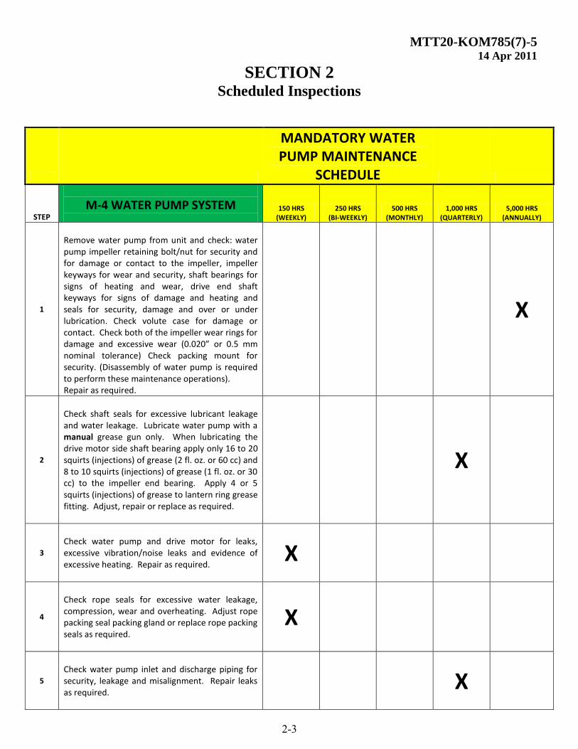
MANDATORY WATER PUMP MAINTENANCE
SCHEDULE
STEP
M-4 WATER PUMP SYSTEM
150 HRS (WEEKLY)
250 HRS (BI-WEEKLY)
500 HRS (MONTHLY)
1,000 HRS (QUARTERLY)
5,000 HRS (ANNUALLY)
1
Remove water pump from unit and check: water pump impeller retaining bolt/nut for security and for damage or contact to the impeller, impeller keyways for wear and security, shaft bearings for signs of heating and wear, drive end shaft keyways for signs of damage and heating and seals for security, damage and over or under lubrication. Check volute case for damage or contact. Check both of the impeller wear rings for damage and excessive wear (0.020” or 0.5 mm nominal tolerance) Check packing mount for security. (Disassembly of water pump is required to perform these maintenance operations). Repair as required.
X
2
Check shaft seals for excessive lubricant leakage and water leakage. Lubricate water pump with a manual grease gun only. When lubricating the drive motor side shaft bearing apply only 16 to 20 squirts (injections) of grease (2 fl. oz. or 60 cc) and 8 to 10 squirts (injections) of grease (1 fl. oz. or 30 cc) to the impeller end bearing. Apply 4 or 5 squirts (injections) of grease to lantern ring grease fitting. Adjust, repair or replace as required.
X
3
Check water pump and drive motor for leaks, excessive vibration/noise leaks and evidence of excessive heating. Repair as required.
X
4
Check rope seals for excessive water leakage, compression, wear and overheating. Adjust rope packing seal packing gland or replace rope packing seals as required.
X
5
Check water pump inlet and discharge piping for security, leakage and misalignment. Repair leaks as required.
X
MTT20-KOM785(7)-5 14 Apr 2011
SECTION 2 Scheduled Inspections
2-4(Blank)
MTT20-KOM785(7)-5 14 Apr 2011
SECTION 3 Special Inspections
3-1
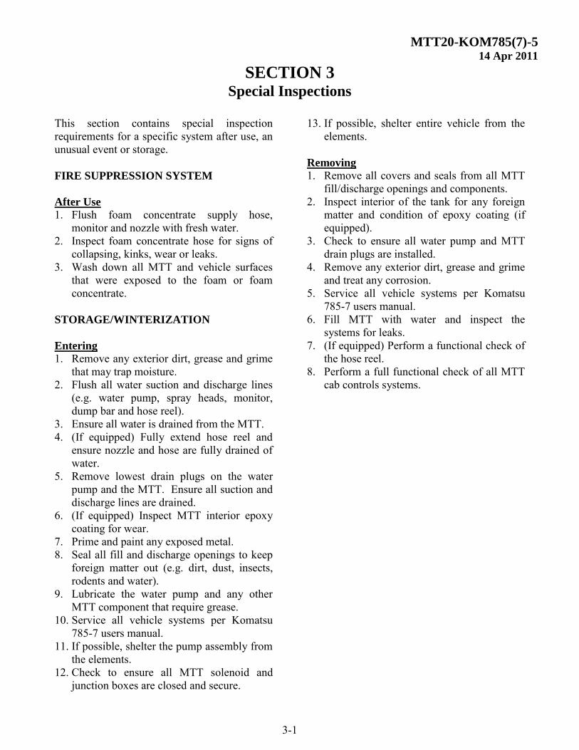
This section contains special inspection requirements for a specific system after use, an unusual event or storage. FIRE SUPPRESSION SYSTEM After Use 1. Flush foam concentrate supply hose,
monitor and nozzle with fresh water. 2. Inspect foam concentrate hose for signs of
collapsing, kinks, wear or leaks. 3. Wash down all MTT and vehicle surfaces
that were exposed to the foam or foam concentrate.
STORAGE/WINTERIZATION
Entering
1. Remove any exterior dirt, grease and grime that may trap moisture.
2. Flush all water suction and discharge lines (e.g. water pump, spray heads, monitor, dump bar and hose reel).
3. Ensure all water is drained from the MTT. 4. (If equipped) Fully extend hose reel and
ensure nozzle and hose are fully drained of water.
5. Remove lowest drain plugs on the water pump and the MTT. Ensure all suction and discharge lines are drained.
6. (If equipped) Inspect MTT interior epoxy coating for wear.
7. Prime and paint any exposed metal. 8. Seal all fill and discharge openings to keep
foreign matter out (e.g. dirt, dust, insects, rodents and water).
9. Lubricate the water pump and any other MTT component that require grease.
10. Service all vehicle systems per Komatsu 785-7 users manual.
11. If possible, shelter the pump assembly from the elements.
12. Check to ensure all MTT solenoid and junction boxes are closed and secure.
13. If possible, shelter entire vehicle from the elements.
Removing 1. Remove all covers and seals from all MTT
fill/discharge openings and components. 2. Inspect interior of the tank for any foreign
matter and condition of epoxy coating (if equipped).
3. Check to ensure all water pump and MTT drain plugs are installed.
4. Remove any exterior dirt, grease and grime and treat any corrosion.
5. Service all vehicle systems per Komatsu 785-7 users manual.
6. Fill MTT with water and inspect the systems for leaks.
7. (If equipped) Perform a functional check of the hose reel.
8. Perform a full functional check of all MTT cab controls systems.
MTT20-KOM785(7)-5 14 Apr 2011
SECTION 3 Special Inspections
3-2(Blank)
MTT20-KOM785(7)-5 14 Apr 2011
SECTION 4 Recommended Support Parts
4-1
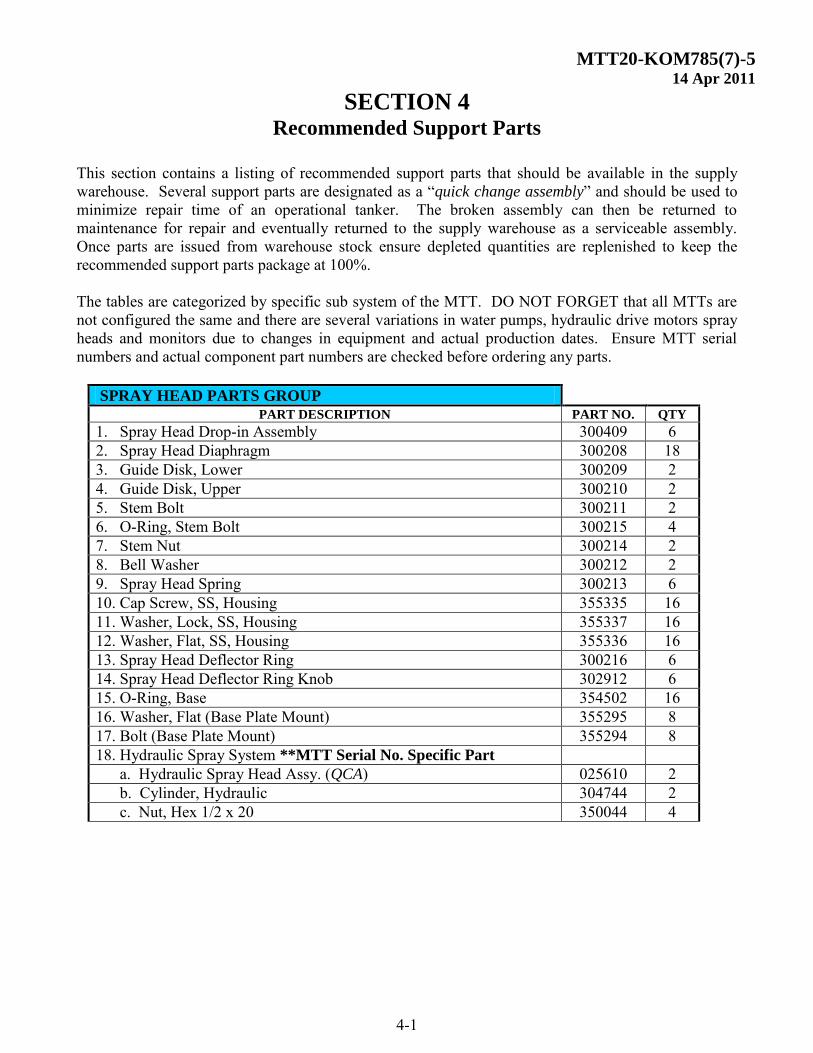
This section contains a listing of recommended support parts that should be available in the supply warehouse. Several support parts are designated as a “quick change assembly” and should be used to minimize repair time of an operational tanker. The broken assembly can then be returned to maintenance for repair and eventually returned to the supply warehouse as a serviceable assembly. Once parts are issued from warehouse stock ensure depleted quantities are replenished to keep the recommended support parts package at 100%. The tables are categorized by specific sub system of the MTT. DO NOT FORGET that all MTTs are not configured the same and there are several variations in water pumps, hydraulic drive motors spray heads and monitors due to changes in equipment and actual production dates. Ensure MTT serial numbers and actual component part numbers are checked before ordering any parts.
SPRAY HEAD PARTS GROUP
PART DESCRIPTION PART NO. QTY
1. Spray Head Drop-in Assembly 300409 6 2. Spray Head Diaphragm 300208 18 3. Guide Disk, Lower 300209 2 4. Guide Disk, Upper 300210 2 5. Stem Bolt 300211 2 6. O-Ring, Stem Bolt 300215 4 7. Stem Nut 300214 2 8. Bell Washer 300212 2 9. Spray Head Spring 300213 6 10. Cap Screw, SS, Housing 355335 16 11. Washer, Lock, SS, Housing 355337 16 12. Washer, Flat, SS, Housing 355336 16 13. Spray Head Deflector Ring 300216 6 14. Spray Head Deflector Ring Knob 302912 6 15. O-Ring, Base 354502 16 16. Washer, Flat (Base Plate Mount) 355295 8 17. Bolt (Base Plate Mount) 355294 8 18. Hydraulic Spray System **MTT Serial No. Specific Part
a. Hydraulic Spray Head Assy. (QCA) 025610 2 b. Cylinder, Hydraulic 304744 2
c. Nut, Hex 1/2 x 20 350044 4
MTT20-KOM785(7)-5 14 Apr 2011
SECTION 4 Recommended Support Parts
4-2
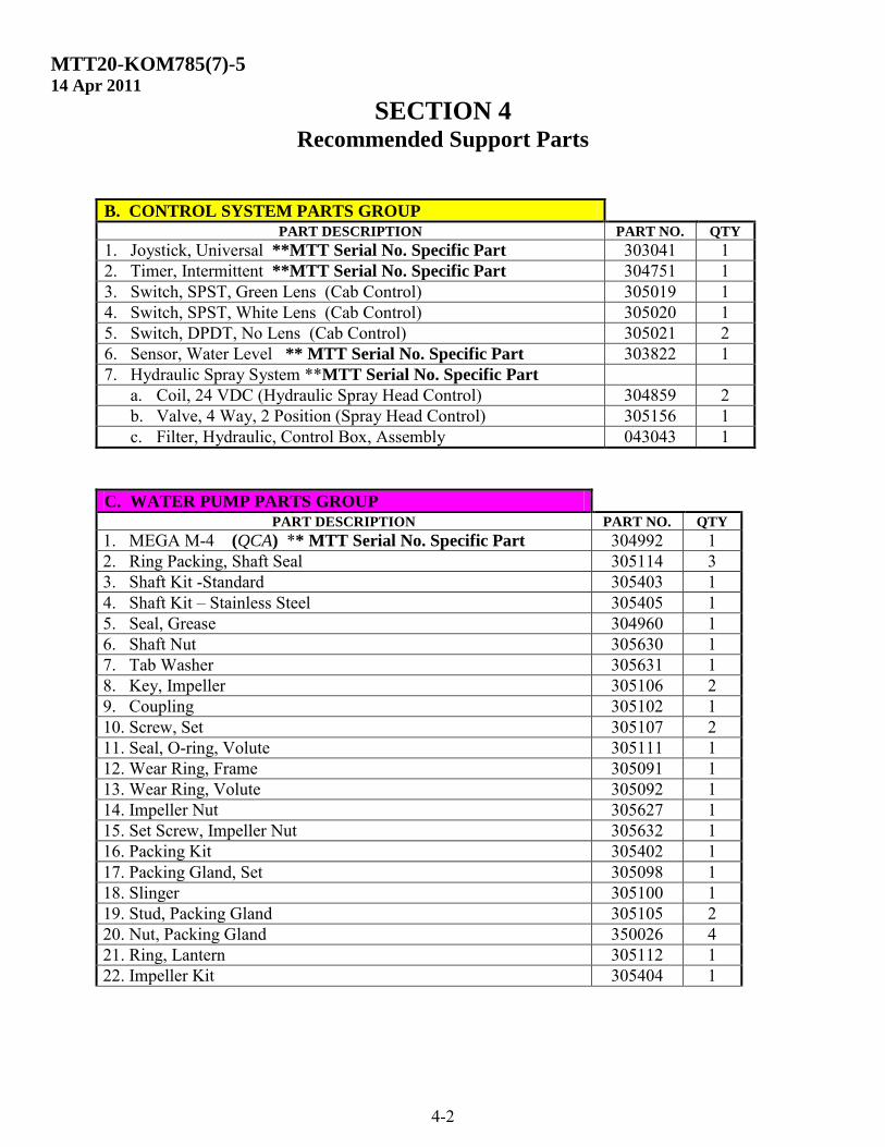
B. CONTROL SYSTEM PARTS GROUP
PART DESCRIPTION PART NO. QTY
1. Joystick, Universal **MTT Serial No. Specific Part 303041 1 2. Timer, Intermittent **MTT Serial No. Specific Part 304751 1 3. Switch, SPST, Green Lens (Cab Control) 305019 1 4. Switch, SPST, White Lens (Cab Control) 305020 1 5. Switch, DPDT, No Lens (Cab Control) 305021 2 6. Sensor, Water Level ** MTT Serial No. Specific Part 303822 1 7. Hydraulic Spray System **MTT Serial No. Specific Part
a. Coil, 24 VDC (Hydraulic Spray Head Control) 304859 2 b. Valve, 4 Way, 2 Position (Spray Head Control) 305156 1 c. Filter, Hydraulic, Control Box, Assembly 043043 1
C. WATER PUMP PARTS GROUP PART DESCRIPTION PART NO. QTY
1. MEGA M-4 (QCA) ** MTT Serial No. Specific Part 304992 1 2. Ring Packing, Shaft Seal 305114 3 3. Shaft Kit -Standard 305403 1 4. Shaft Kit – Stainless Steel 305405 1 5. Seal, Grease 304960 1 6. Shaft Nut 305630 1 7. Tab Washer 305631 1 8. Key, Impeller 305106 2 9. Coupling 305102 1 10. Screw, Set 305107 2 11. Seal, O-ring, Volute 305111 1 12. Wear Ring, Frame 305091 1 13. Wear Ring, Volute 305092 1 14. Impeller Nut 305627 1 15. Set Screw, Impeller Nut 305632 1 16. Packing Kit 305402 1 17. Packing Gland, Set 305098 1 18. Slinger 305100 1 19. Stud, Packing Gland 305105 2 20. Nut, Packing Gland 350026 4 21. Ring, Lantern 305112 1 22. Impeller Kit 305404 1
MTT20-KOM785(7)-5 14 Apr 2011
SECTION 4 Recommended Support Parts
4-3
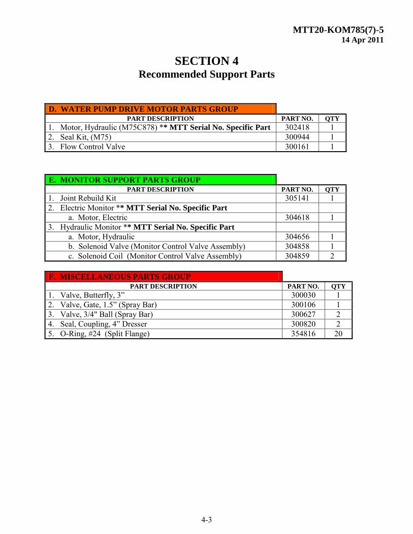
D. WATER PUMP DRIVE MOTOR PARTS GROUP PART DESCRIPTION PART NO. QTY
1. Motor, Hydraulic (M75C878) ** MTT Serial No. Specific Part 302418 1 2. Seal Kit, (M75) 300944 1 3. Flow Control Valve 300161 1
E. MONITOR SUPPORT PARTS GROUP PART DESCRIPTION PART NO. QTY
1. Joint Rebuild Kit 305141 1 2. Electric Monitor ** MTT Serial No. Specific Part
a. Motor, Electric 304618 1 3. Hydraulic Monitor ** MTT Serial No. Specific Part
a. Motor, Hydraulic 304656 1 b. Solenoid Valve (Monitor Control Valve Assembly) 304858 1 c. Solenoid Coil (Monitor Control Valve Assembly) 304859 2
F. MISCELLANEOUS PARTS GROUP
PART DESCRIPTION PART NO. QTY
1. Valve, Butterfly, 3” 300030 1 2. Valve, Gate, 1.5” (Spray Bar) 300106 1 3. Valve, 3/4" Ball (Spray Bar) 300627 2 4. Seal, Coupling, 4” Dresser 300820 2 5. O-Ring, #24 (Split Flange) 354816 20
MTT20-KOM785(7)-5 14 Apr 2011
SECTION 4 Recommended Support Parts
4-4(Blank)
NOTES
.