Embed Size (px)
Citation preview

CODE SCHEDULING AND OPTIMIZATION FOR A
SUPERSCALAR X86 MICROPROCESSOR
BY
WAYNE FRANCIS DUGAL
B.S, Purdue University, 1985
THESIS
Submitted in partial ful�llment of the requirements
for the degree of Master of Science in Electrical Engineering
in the Graduate College of the
University of Illinois at Urbana-Champaign, 1995
Urbana, Illinois

ACKNOWLEDGEMENTS
I would first like to thank my advisor, Professor Wen-mei Hwu, for his guidance and
support. I also would like to thank the IMPACT group, in general, and Dave Gallagher and Ben
Sander, in particular, for their participation in helpful discussions. Several people in AMD's
KRYPTON group have provided valuable guidance and support, especially Dave Christie and
Dave Witt. Finally, I thank my wife, Kelly, and my three children, Phillip, Lauren, and Andrew,
for their love and understanding.
iii

TABLE OF CONTENTS
Page
1. INTRODUCTION ....................................................................................................................1
2. IMPACT...................................................................................................................................32.1 An Introduction to Lcode ............................................................................................4
2.1.1 File layout.....................................................................................................42.1.2 Function layout.............................................................................................52.1.3 Control block layout......................................................................................62.1.4 Instruction layout..........................................................................................72.1.5 Data layout....................................................................................................8
2.2 Differences between Lcode and Mcode........................................................................102.3 Code Generator Structure............................................................................................11
2.3.1 Code annotation ............................................................................................112.3.2 Optimization, scheduling and register allocation.............................................122.3.3 Producing assembly code...............................................................................13
3. KRYPTON ARCHITECTURE DESCRIPTION.......................................................................143.1 Instruction Decode ......................................................................................................153.2 Integer Functional Units...............................................................................................16
3.2.1 Branch functional unit...................................................................................173.2.2 ALU0/Shifter functional unit.........................................................................173.2.3 ALU1 functional unit.....................................................................................17
3.3 Floating Point Functional Unit.....................................................................................183.4 Load/Store Functional Unit..........................................................................................193.5 Reorder Buffer.............................................................................................................193.6 Out-of-order-issue/completion.....................................................................................20
3.6.1 Register renaming..........................................................................................213.6.2 Out-of-order-issue/completion using TAGS...................................................22
4. KRYPTON MACHINE DESCRIPTION LANGUAGE DEVELOPMENT...............................254.1 MDES Overview.........................................................................................................26
4.1.1 Register_Files................................................................................................264.1.2 IO_Sets.........................................................................................................274.1.3 IO_Items.......................................................................................................284.1.4 Resources......................................................................................................294.1.5 ResTables......................................................................................................304.1.6 Latencies.......................................................................................................314.1.7 Operation_Class............................................................................................324.1.8 Operations.....................................................................................................33
iv

4.2 KRYPTON MDES ......................................................................................................344.2.1 Alu selection.................................................................................................344.2.2 FAST and MROM interaction.......................................................................364.2.3 Two and three ROP instructions....................................................................36
5. INSTRUCTION SELECTION..................................................................................................405.1 Arithmetic and Logical Operations Using Only Memory Variables...............................425.2 Arithmetic and Logical Operations Using Register and Memory Variables...................455.3 Compare Instructions Using Memory Variables............................................................485.4 Results.........................................................................................................................50
6. CONCLUSIONS ......................................................................................................................52
REFERENCES .........................................................................................................................53
v

1. INTRODUCTION
Optimizing compilers for superscalar architectures perform scheduling and optimizations to
expose and exploit Instruction-Level-Parallelism (ILP). This problem is relatively well-understood
for the typical Reduced-Instruction-Set-Computer (RISC) architectures. IMPACT, an optimizing
compiler developed at the University of Illinois, has optimized code for several RISC processors.
However, any superscalar X86 architecture presents a new problem, its small register file
provides only eight registers compared to the 32 or more provided by typical RISC processors.
This makes many of the techniques used by IMPACT to exploit ILP less beneficial.
This thesis is a description of the changes made to the IMPACT compiler to support a
superscalar X86 processor, AMD's KRYPTON. Two changes to the IMPACT compiler are
discussed in this thesis. First, KRYPTON was defined to the IMPACT compiler to enhance
scheduling. Second, code generation optimizations were performed to convert register variables
to memory variables on as many instructions as possible. This was done to reduce the limitation of
the small X86 register file.
1

This thesis, study is divided into six chapters. Chapter 2 provides background of the
IMPACT compiler. It gives an overview on the IMPACT compiler, gives an introduction to
Lcode and describes the code generation process.
Chapter 3 is a description of KRYPTON, including a description of all its functional units.
This chapter focuses on a description of the functional units because a firm understanding of them
is required to develop a good Machine Description Language (MDES). It also describes the use
of a reorder buffer and discusses the use of register renaming and use of tags for out-of-order-
issue and out-of-order-completion, similar to what is used in KRYPTON.
Chapter 4 describes the development of the KRYPTON MDES. The MDES is used to
describe KRYPTON's resources to the scheduler which allows the scheduler to best use these
resources. It provides solutions to three scheduling problems presented by KRYPTON.
Chapter 5 discusses the problems caused by the small X86 register file when generating
code for KRYPTON. Three solutions to lessen the effects of the small register file are explained.
These solutions are code generation optimizations that take advantage of X86's ability to use
memory operands. Chapter 6 contains the conclusions.
2

2. IMPACT
The IMPACT [5] compiler is a generalized C compiler that can generate optimized code
for various architectures and machine resource configurations. It also implements new research
optimizations so that their effect on code can be analyzed.
IMPACT is divided into three distinct parts based on the intermediate code representation
used. The highest level is called PCode and is a parallel C code representation with intact loop
constructs. Memory system optimizations, loop-level transformations and memory dependence
analysis takes place at this level. The next lower level is called Hcode and is a simplified C
representation with only simple if-then-else and goto control flow constructs. Statement-level
profiling, profile-guided code layout and function inline expansion are performed at this level.
The final and lowest code representation is called Lcode. Lcode is a generalized register
transfer language. It is similar to most RISC instruction-based assembly languages. At the
Lcode level, classic machine independent optimizations are performed. Superblock [3]
compilation techniques are also performed at the Lcode level. Superblock support includes
3

superblock formation using execution profile information, superblock classical optimization, and
superblock ILP optimization.
IMPACT code generation is a process that converts Lcode instructions into an assembly
language. This section is an introduction to the code generation process. To do this, Section 2.1
introduces Lcode. Section 2.2 discusses the extensions to Lcode that make Mcode and Section
2.3 details the steps of code generation.
2.1 An Introduction to Lcode
In order to fully understand the code generation process, a familiarity with Lcode is
necessary. Lcode is an instruction set for a load/store architecture that supports unlimited virtual
registers. It is broken down into data and function blocks. The functions are composed of control
blocks containing the Lcode instructions. Different phases of compilation can change the Lcode
instructions. These phases will be highlighted as they are discussed in this chapter.
Only the external representation of Lcode is discussed. For a description of the most
important data structures used by the C programs, see [2].
2.1.1 File layout
A typical Lcode file may be composed of a data section and one or more functions. The
data section defines both static and dynamic variables, that are aligned to memory locations
specified by the mspec [1] file. Data types include unsigned character (1 byte), signed character (1
byte), unsigned short (2 bytes), signed short (2 bytes), unsigned integer (4 bytes), signed integer
(4 bytes), single-precision float (4 bytes), and double precision float (8 bytes). All integers are
4

expressed as two's complement number representation and all floating point values are expressed
in IEEE floating point representation.
2.1.2 Function layout
Figure 2.1 shows the layout of a typical function in a Lcode file. The first line of a function,
preceded by the keyword function, contains the name of the function (name) and the typical
execution count of the function (exec_cnt). Execution count information may be gained
accurately from profiling or estimated static analysis. The first control block always contains the
prologue that defines return register type, local variable requirements in bytes and outgoing
parameter requirements in bytes.
(function name exec_cnt) (cb "prologue") (cb ...)
. . .
(cb "epilogue")(end name)
Figure 2.1: Lcode Function Layout
As a minimum, a function will contain a control block with the prologue and a last control
block with an epilogue. Therefore, there are a minimum of two control blocks per function. A
function will never have more than one entry point, but may have multiple exit points. It is
possible to have the epilogue duplicated in more than one control block because of compiler
optimizations.
5

2.1.3 Control block layout
Figure 2.2 shows the layout of a typical control block. Control blocks may have one or
more exit points, but only one entry point. Control blocks with an one exit point (fall through or
branch) at the bottom of the block are the same as basic blocks; control blocks with multiple
exit points are called superblocks.
A control block begins with the keyword Cb followed by a unique identification number
(id) and an execution count (Cb_exec_cnt). The execution count shows profiled-based or static
information about number of times the control block has been executed.
(cb id cb_exec_cnt (flow cond dest cnt)
... (flow cond dest cnt)
(op ...) ... (op ...)
[(branch_op ...)] ...
[(branch_op ...)]
Figure 2.2: Lcode Control Block Layout
Next, the flow information is given and preceded by the keyword flow. Flow information
is composed of three fields: the condition by which the destination will be followed (cond), a
destination control block number if the condition is met (dest), and the number of times that the
condition was met during profiling (cnt). It should be noted that unless profile information is
available, the cnt field here will always be 0.0 for all paths.
If a control block has no branch at the end, the condition field is ignored and the destination
is the next sequential control block. The condition field also will be ignored if the last instruction
6

of the basic block is an unconditional branch. A basic block with a conditional branch will contain
flow information for the taken and not taken cases.
Superblocks may contain multiple conditional branches but only one unconditional branch.
Due to the multiple exit points in superblocks, Lcode instructions do not necessarily have the
same execution count as specified in the control block header. The execution count of any
instruction following a branch is computed by subtracting the cut fields of all the preceding branch
instructions from Cb_exec_cnt.
2.1.4 Instruction layout
Lcode instruction begins with the entry op and is composed of four major parts: operation
number, opcode, operands and attributes, as shown in Figure 2.3. The operation number is
unique for each Lcode instruction in the function.
The opcode signifies the Lcode operation to perform. These groups are broken down into
ALU operations, memory access and control flow. For a detailed description of each opcode and
its required parameters, see [5].
(op op_num) (opcode ((dest1_type dest_value) ... (dest3_type dest_value))
((src1_type src1_value) ... (src4_type src4_value)) ((attr_name attr_value) ... )))
Figure 2.3: Lcode Instruction Layout
Lcode instructions are not limited to three destination fields and four source fields. It can
support a variable number of destination and source fields. This value is set in a STD_PARMS
file. The opcode shows the number and type of fields required at any given time. However, in
7

some instances such as memory stores, a source field is used as the destination of the store. This
is to prevent any incorrect register dependencies when using address indirect.
Each operand has two fields. The first field is a type that can be register (r), label (l),
integer (i), single precision floating point (f), double precision floating point (f2), a macro (mac)
or a control block number (cb). The second field is the data of the specified type.
2.1.5 Data layout
There are five data classifications as shown in Figure 2.4. A complete description of each
operation in the classes is covered in [5]. Class 1 currently can have only an op value of reserve.
This indicates a block of memory starting at the current point with value integer number of bytes
reserved.
Class 1: (op value)
Class 2: (op name)
Class 3: (op expr1 expr2)
Class 4: (op value name)
Class 5: (op size name expr*)
Figure 2.4: Lcode Data Item Layout
Class 2 can have only op values of void and global. In both cases, name is a label that may
be used for reference purposes only. It is illegal to load from or to store to either of these
locations. Global is used to promote the scope of the label and make it visible outside the file.
8
Class 3 can have op values of wb, ww, wi, wf, wf2, and ws, which are used to write a
value to an address determined by the computation result of expr1. The sizes of these fields are
byte, word, integer, float, double and string pointer, respectively. These are discussed in more
detail in Section 2.1.1. The second expression (expr2) must evaluate the type defined by op.
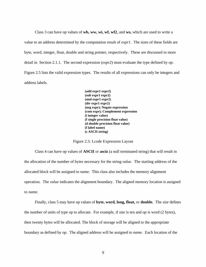
Figure 2.5 lists the valid expression types. The results of all expressions can only be integers and
address labels.
(add expr1 expr2)(sub expr1 expr2)(mul expr1 expr2)(div expr1 expr2)(neg expr); Negate expression(com expr); Complement expression(i integer value)(f single precision float value)(d double precision float value)(l label name)(s ASCII string)
Figure 2.5: Lcode Expression Layout
Class 4 can have op values of ASCII or asciz (a null terminated string) that will result in
the allocation of the number of bytes necessary for the string value. The starting address of the
allocated block will be assigned to name. This class also includes the memory alignment
operation. The value indicates the alignment boundary. The aligned memory location is assigned
to name.
Finally, class 5 may have op values of byte, word, long, float, or double. The size defines
the number of units of type op to allocate. For example, if size is ten and op is word (2 bytes),
then twenty bytes will be allocated. The block of storage will be aligned to the appropriate
boundary as defined by op. The aligned address will be assigned to name. Each location of the
9

block, starting with the first at the aligned address, will be initialized by one or more expr. It is
illegal to have more expressions than locations to be initialized.
2.2 Differences between Lcode and Mcode
Mcode is machine specific Lcode. Extensions have been added to Lcode to provide
distinctions between machine architectures. This facilitates the development of generic modules
that perform Mcode optimizations, register allocation and instruction scheduling, as discussed in
Section 2.3.
One extension is the use of specific machine opcodes . These opcodes are used to
propagate information from one phase of code generation to another. In the X86 code generator,
these are X86-specific instructions. For example, X86 supports an operation to load the effective
address (lea) into a register. The three optimizations explained in Section 5 all use at least one
machine specific opcode. None of these opcodes are supported by Lcode. Machine specific
opcodes are also referred to as "proc_opc."
Another extension is the use of machine specific annotations. These can be used to show a
divergence from the standard use of an opcode. For example, X86 allows its 32-bit registers to
be used as 32-bit registers, 16-bit registers or 8-bit registers. The attribute "short_opr"
distinguishes which version of the register is being used. If the 8-bit version is used, the attribute
"short_opr 1" is added to the operation. Similarly, "short_opr 2" is added for a 16-bit register.
Other attributes the X86 code generator uses include ill_reg and cisc_compare.
10

2.3 Code Generator Structure
The three main phases to code generation are shown in Figure 2.6. During phase I the
compiler performs code annotation. During phase II, the compiler performs Mcode optimization,
scheduling and register allocation. During phase III, the compiler converts the final Mcode to
assembly language. These phases will be discussed in detail in the following sections.
M codeLcode
Assem bly Code
Pre-pass Code Scheduling
Pre-pass CodeOptimizations
Register Allocation
Post-pass Code Scheduling
Post-pass Code Annotation
PHASE I
Code Annotation
PHASE II
GenerateAssembly Code
PHASE III
M code
Figure 2.6: Block Diagram of IMPACT Code Generator
2.3.1 Code annotation
This phase involves converting Lcode to Mcode. During this process, instructions that are
supported by the X86 family are directly converted to Mcode. Any unsupported Lcode
11

instructions are converted to Mcode instructions. For example, the Lcode language supports three
operand instructions and the X86 assembly language supports only two operand instructions.
During this phase all three operand instructions are converted to two operand instructions.
2.3.2 Optimization, scheduling and register allocation
Phase I code annotation can create redundant instructions. Therefore, the first task of this
phase is to perform the Mcode optimizations. This is also where machine specific optimizations
are done. For example, the X86 instructions set allows arithmetic and logical operations to use
memory variables. An optimization was developed to change certain instructions to instructions
that use memory variables.
The next step in this phase is pre-pass scheduling. For typical RISC architectures, this
provides a better schedule since it arranges instructions before register allocation.
Register allocation converts the Lcode virtual registers to machine specific registers. If
there are insufficient registers, the register allocator will insert necessary spill and fill instructions
to break up the live range of the register.
Post-pass code annotation and optimizations are performed after register allocation.
Instructions that are dependent on information provided by the register allocator are annotated
here. Dead code removal is an example of a post-pass optimization. The last step in this phase is
post-pass scheduling.
12

2.3.3 Producing assembly code
The third phase converts the optimized Mcode file to the appropriately formatted assembly
code targeted for commercial assemblers. The X86 code generator currently supports two
different assemblers.
13

3. KRYPTON ARCHITECTURE DESCRIPTION
KRYPTON is a superscalar X86 processor. It implements the X86 instruction set with all
Pentium extensions. It accomplishes this by converting X86 instructions to a sequence of RISC-
like-operations, or ROPs. These ROPs are issued to a superscalar RISC core that supports four
ROP issues, five ROP results, and up to 16 speculatively executed ROPs.
This core has the capability of speculative issue through unresolved branches. The branch
prediction information is held with every 16 byte block in the instruction cache. Up to four ROPs
can be retired per clock cycle. This can include up to four ALU operations, four load operations,
one store operation or one branch operation.
The RISC core consist of one ALU/Shifter, one ALU, one pipelined floating point unit, one
branch unit, one load/store unit (capable of executing two ROPS), a sixteen entry reorder buffer
and an extended register file. Figure 3.1 shows this RISC core.
14

BranchALU0Shifter ALU1
LOAD/ STOREFPU
4-wide ROP DISPATCH Operand Steering
RegisterFile
Fast 0 Fast 1 Fast 2 Fast 3
MROM
ReorderBuffer
Figure 3.1: KRYPTON's RISC Core
3.1 Instruction Decode
All X86 instructions are decoded by a complicated decode unit into ROPs. All X86
instructions contain at least one ROP, and X86 instructions that contain three or fewer ROPs are
decoded and dispatched on "FAST" decoders. All X86 instructions that take four or more ROPs
are decoded directly by a micro-coded-ROM (MROM).
If a MROM instruction is encountered, it cannot dispatch with FAST ROPS, and FAST
ROPS cannot dispatch until the MROM instruction is dispatched. In other words, FAST ROPS
cannot be combined with MROM ROPS. For example, a MROM routine of five ROPs will take
two cycles to issue (assuming no resource constraints), and FAST ROPS cannot be issued with
15

the MROM ROPs. Similarly, a MROM routine cannot begin to issue in the same cycle with FAST
ROPS even if dispatch positions and resources are available. This is illustrated in Figure 3.2.
Cycle Dispatch 1 Dispatch 2 Dispatch 3 Dispatch 4
1 FAST ROP FAST ROP 2 MROM ROP MROM ROP MROM ROP MROM ROP 3 MROM ROP 4 FAST ROP FAST ROP FAST ROP FAST ROP
Figure 3.2: Issue of MROM routines
To support this decoding, Krypton has a larger register file than the X86. Figure 3.3 shows
how an X86 instruction might be decoded and shows the use of the extra registers. The X86
instruction in Figure 3.3 adds two to a memory location and stores the result in that memory
location. The three ROPS generated are a load form memory, an add, and a store to memory.
X86 instruction => MEM = MEM + 2
ROP1 => TEMP_REG1 <- MEMROP2 => TEMP_REG1 <- TEMP_REG1 + 2
ROP2 => MEM <- TEMP_REG1
Figure 3.3: X86 Instruction Decode
3.2 Integer Functional Units
The integer functional units that the four ROP dispatch positions can issue to are:
1. Branch functional unit,
2. ALU0/Shifter functional unit, and
3. ALU1 functional unit.
16

All integer functional units have first-in-first-out (FIFO) reservation stations. This means
out-of-order issue is not supported within functional units, only between functional units. The
reservation station is held until the operation leaves the functional unit.
3.2.1 Branch functional unit
The Branch functional unit has a one cycle latency. One new ROP can be accepted per
clock cycle. It has a two entry reservation station to hold two speculative ROPs, and it handles all
X86 branch, call and return instructions. It is available to all MROM routines as well as FAST
ROPs.
3.2.2 ALU0/Shifter functional unit
The ALU0/Shifter functional unit has a one cycle latency. One new ROP can be accepted
per clock cycle. It has a two entry reservation station to hold two speculative ROPs. All X86
arithmetic and logical instructions go through this block or ALU1. In addition, all shift and rotate
instructions are handled by this unit. It is available to all MROM routines as well as to FAST
ROPs.
3.2.3 ALU1 functional unit
The ALU1 functional unit is identical to the ALU0/Shifter except it handles only arithmetic
and logical instructions. Combined with ALU0, up to two integer results can be calculated per
cycle.
17

3.3 Floating Point Functional Unit
The Floating Point functional unit has only one reservation station that holds two ROPs. It
takes two ROPs to perform 80-bit calculations. The two 40-bit ROPs are combined in the
reservation station before being issued to the first stage of the Floating Point unit. This
combining operation takes one cycle. The Floating Point unit consist of an adder, a multiplier,
and a shared rounder.
The adder has two stages; each has a one cycle latency. The adder forwards its result to the
rounder. The latency of the rounder is one cycle. One cycle is lost combining the two 40-bit
ROPs, yielding a net latency of four cycles for a floating point add. Floating point adds can be
issued at a rate of one every cycle.
The multiplier has a seven cycle latency for extended precision multiply. It uses a 32x32
multiplier and multi-cycles it for the 64-bit mantissa required in extended precision. The 32x32
multiplier multi-cycles for four cycles, a partial products adder takes one cycle, the rounder takes
one cycle, and one cycle is lost combining the two 40-bit ROPs. This yields a net latency of seven
cycles.
The 32x32 multiplier is also used for integer multiply. The latency for an integer multiply is
four cycles. The latency of the 32x32 multiply is one cycle, a partial products adder takes one
cycle, the rounder takes one cycle and one cycle is lost combining the two 40-bit ROPs. This
yields a net latency of four cycles. Floating point multiplies can be issued every four cycles and
integer multiplies can be issued every cycle.
18

3.4 Load/Store Functional Unit
The Load/Store functional unit provides a four entry reservation station and allows two load
or store operations to be issued per clock cycle. The latency of a load store operation is one cycle.
This latency includes checking for a hit/miss in the data cache, and if it is a hit, forwarding the
result to the result bus. Up to two load operations can simultaneously access the data cache and
forward the result to result buses.
All stores are done as read-modify-write operations. The read portion is similar to a load
except that the data is not written to the result busses. Instead, it is merged with the store data.
This information is written to the store buffer. The store buffer writes back to the data cache at
any available time after it is retired. These reservation stations are also FIFO.
3.5 Reorder Buffer
A reorder buffer can be thought of as a queue of speculatively executed instructions. This
queue tail corresponds to the location of the next speculative instruction, and the head
corresponds to the next instruction to be retired.
Instructions are issued and appended to the tail of the queue by allocating entries in the
reorder buffer. Their relative position on the queue now corresponds to the speculative program
order. If a reference is made to a particular register that has a value or values in the reorder
buffer, then the latest update of that register is determined by the relative position in the queue.
Reorder buffers allow multiple updates of any register up to the length of the queue.
19

Branches are handled by an indication in the reorder buffer that a branch has been
successfully predicted as taken. The location of the branch target is also recorded. Mis-predicted
branches are handled by also indicating the entry allocated within the reorder buffer within a
branch has been mispredicted, and then invalidating all speculative entries after that branch. This
also frees up reorder buffer entries for the correct path that is concurrently being fetched.
Speculative load and store operations also benefit. Loads directly read data cache and
return the value to the speculative location within the reorder buffer; thus, loads are easily
forwarded to the subsequent register reference.
Stores benefit by determining a hit or miss from a read of the tags. This information is
driven back to the reorder buffer while simultaneously holding the entry in a store buffer.
Subsequent loads reference the store buffer in parallel with the data cache. When the store is the
next instruction to retire, the corresponding store buffer entry is released and cleared.
If an exception or mis-prediction occurs, the store buffer entry is locally cleared without
corrupting the data cache. The reorder buffer retires in program order four instructions per cycle.
3.6 Out-of-order-issue/completion
A version of Tomasulo's algorithm [6] is used to implement out-of-order issue in
KRYPTON. The difference is the use of a reorder buffer to do register renaming rather than the
use of a future file as originally proposed by Tomasulo.
20
3.6.1 Register renaming
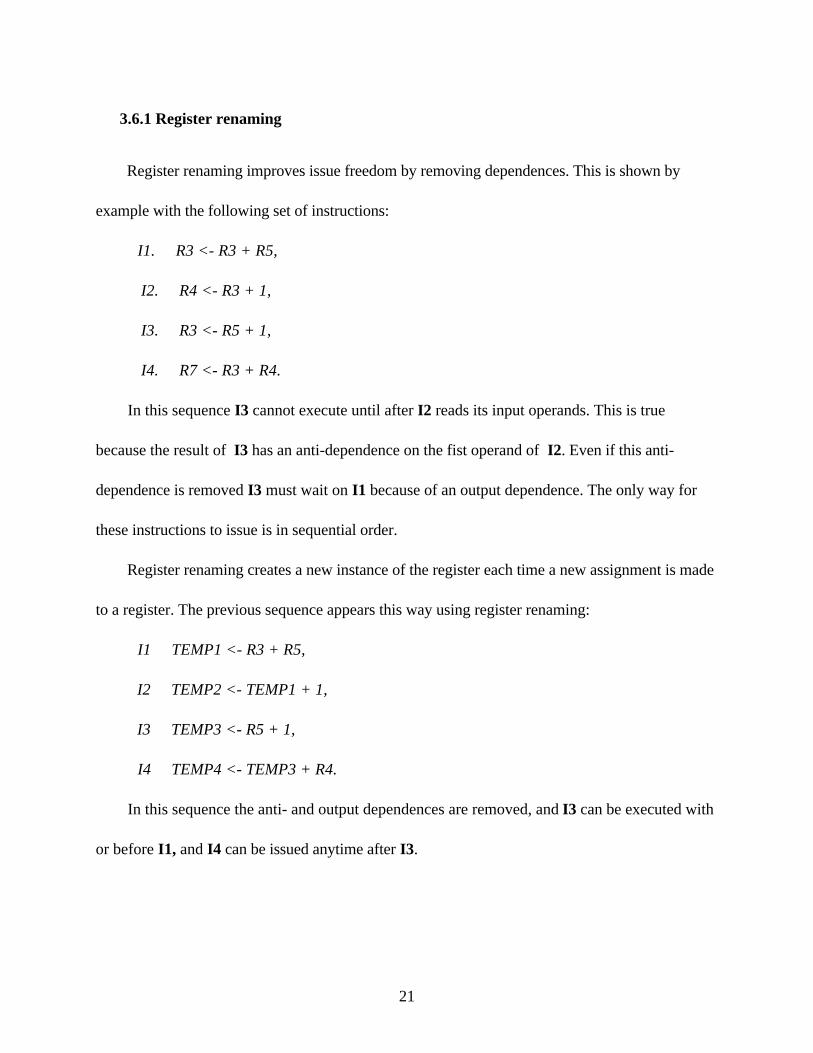
Register renaming improves issue freedom by removing dependences. This is shown by
example with the following set of instructions:
I1. R3 <- R3 + R5,
I2. R4 <- R3 + 1,
I3. R3 <- R5 + 1,
I4. R7 <- R3 + R4.
In this sequence I3 cannot execute until after I2 reads its input operands. This is true
because the result of I3 has an anti-dependence on the fist operand of I2. Even if this anti-
dependence is removed I3 must wait on I1 because of an output dependence. The only way for
these instructions to issue is in sequential order.
Register renaming creates a new instance of the register each time a new assignment is made
to a register. The previous sequence appears this way using register renaming:
I1 TEMP1 <- R3 + R5,
I2 TEMP2 <- TEMP1 + 1,
I3 TEMP3 <- R5 + 1,
I4 TEMP4 <- TEMP3 + R4.
In this sequence the anti- and output dependences are removed, and I3 can be executed with
or before I1, and I4 can be issued anytime after I3.
21

3.6.2 Out-of-order-issue/completion using TAGS
Taking this a step further, and applying a version of Tomasulo's algorithm with an reorder
buffer, TAGS could be used for instructions pending results. These instructions would be stored
in reservation stations until the operands are ready. In the previous sequence and a four issue
machine, Figure 3.4(a) shows the best possible issue sequence.
(a) Best issue sequence using register renaming
CYCLE SLOT1 SLOT2 SLOT3 SLOT4 1 I1 2 I2 I3 3 I4
(b) Best issue sequence using TAGS
CYCLE SLOT1 SLOT2 SLOT3 SLOT4 1 I1 I2 I3 I4
Figure 3.4: Issue Sequences Using Register Renaming and TAGS
Using the concepts of tags for pending operations, the previous sequence would appear
as follows:
I1 TEMP1 <- R3 + R5,
I2 TEMP2 <- TAG_TEMP1 + 1,
I3 TEMP3 <- R5 + 1,
I4 TEMP4 <- TAG_TEMP3 + R4.
Figure 3.4(b) shows the best possible issue sequence for these instructions.
22

It should be noted that I2 and I4 cannot execute in cycle one because they are waiting for
TAGS. However, they can be issued and held in a reservation station. They will execute in the
next cycle when the TAG is forwarded.
One disadvantage of the schedule in Figure 3.4(b) is that a compiler may have found two
instructions elsewhere that were ready to execute in SLOT2, SLOT3 and SLOT4 of cycle one.
Now the compiler no longer has the freedom to schedule the instructions there. This disadvantage
is not valid given the assumption that the previous sequence of instructions was provided by the
compiler as the best possible schedule.
Given a four-issue superscalar machine with four alus and the previous schedule, all four
instructions would be dispatched to the reservation stations in cycle one. I1 would be issued to
and executed by alu0 in cycle one. I2 would be issued to and executed by alu1 in cycle two. This
occurs after it has received its TAG from alu0. I3 would be issued to and executed by alu3 in
cycle one. I4 would be issued to and executed by alu4 in cycle two. This occurs after it has
received its TAG from alu3.
Given the same four-issue superscalar machine with four alus but without the ability to
issue out-of-order, only the I1 would be executed in cycle one. I2 and I3 would be executed in
cycle two, and I4 would be executed in cycle three. The difference is one cycle, which results
from I3 being issued and completed out of order.
The out-of-order issue in the previous example is between functional units - in this case
alu2 and alu3. This is the only way instructions can be issued out-of-order in KRYPTON because
the reservation stations are FIFO. Another type of out-of-order issue is within a functional unit. In
23

this case, if an instruction is waiting for a TAG in a reservation station, a free instruction can
bypass it.
24

4. KRYPTON MACHINE DESCRIPTION LANGUAGE DEVELOPMENT
Scheduling for superscalar processors can be very difficult. To schedule accurately, the
scheduler has to know what resources are available, when they are used and how long they are
used. It also needs to know what combinations of resources are used by each instruction and the
latencies associated with operand in each instruction. The Machine Description Language
(MDES), developed by John Gyllenhaal, provides the capability to describe all of a processor's
resources, instruction latencies, and legal combinations of operands to IMPACT. This allows the
scheduler to develop an optimum schedule for that processor.
Section 4.1 gives an overview of MDES. This overview is needed to understand the next
section, which defines specific problems encountered when developing the KRYPTON MDES
and the solutions to these problems. Examples from the KRYPTON MDES are used throughout
this section. A complete description of MDES is found in [1].
KRYPTON presented many new modeling problems. Section 4.2 discusses three of these
problems and uses examples of the solutions to these problems from the KRYPTON MDES. The
25

problems in increasing order of difficulty are the following: modeling the different alus and
ensuring the correct one was chosen, modeling the interaction of the MROM and the FAST
instructions, and modeling X86 instructions that contain two or three ROPs.
4.1 MDES Overview
This section describes the steps taken to develop a MDES, which is done by showing the
steps used to develop the KRYPTON MDES. Sections 4.1.1, 4.1.2 and 4.1.3 describe how to
define the legal operands. Sections 4.1.4 and 4.1.5 describes how to define the available resources
and how these resources are used. Section 4.1.6 describes instruction latencies. Sections 4.1.7 and
4.1.8 describes how to combine the operands, resources and latencies into an instruction set. This
instruction set can be a subset of the processor's instruction set or a complete set. Either way it is
the set of all Mcode instructions used for that processor.
4.1.1 Register_Files
This section of the MDES is used to define operand types allowed in the X86 assembly
language. All legal register types and constant sizes are enumerated in this section. These names
are used in the IO_Sets section to specify what operand types are allowed for each instruction in
the processor's instruction set. The format of an Register_Files entry follows:
name((capacity static_size rotating_size)(width width_in_bits))),
where
1. name is the register file's or operand type's name,
2. static_size is the number of static registers in the file,
26
3. rotating_size is the number of rotating registers in the file, and
4. width_in_bits is the register width in bits.
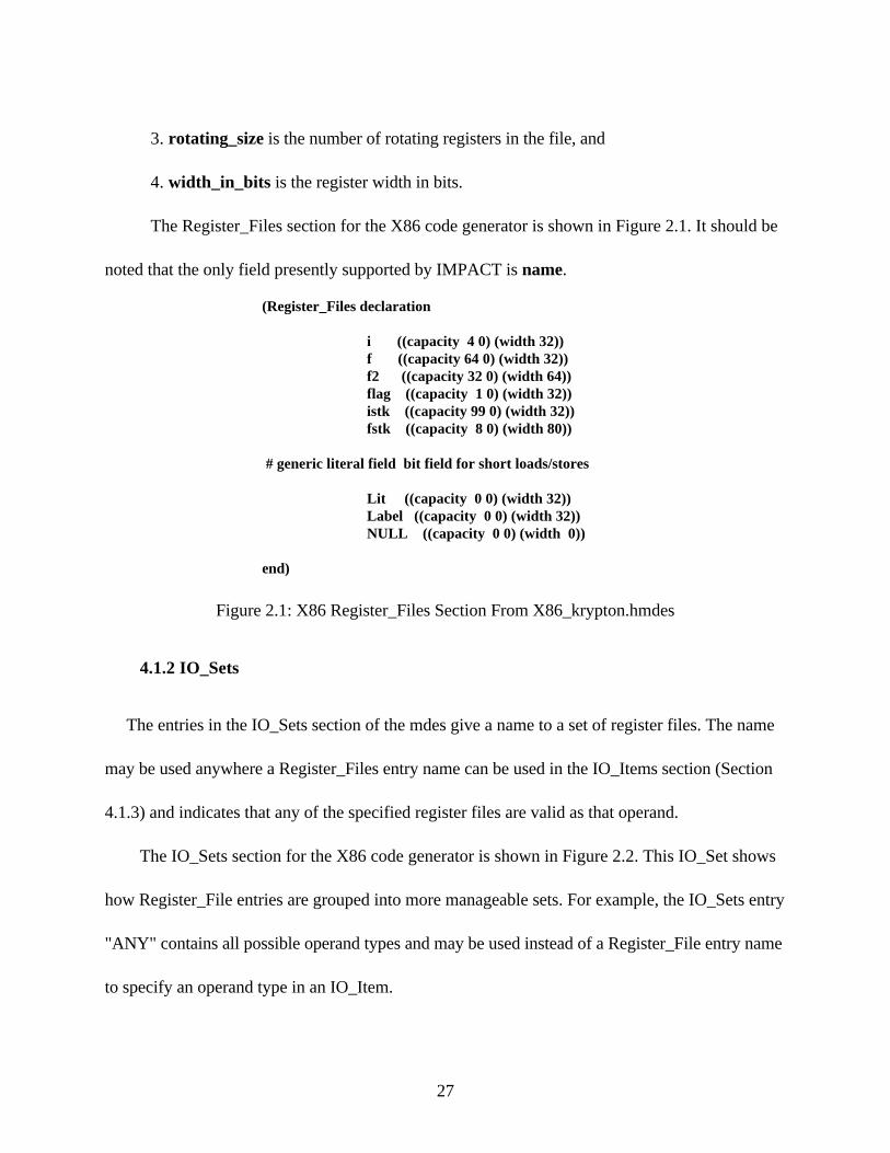
The Register_Files section for the X86 code generator is shown in Figure 2.1. It should be
noted that the only field presently supported by IMPACT is name.
(Register_Files declaration
i ((capacity 4 0) (width 32)) f ((capacity 64 0) (width 32)) f2 ((capacity 32 0) (width 64)) flag ((capacity 1 0) (width 32)) istk ((capacity 99 0) (width 32)) fstk ((capacity 8 0) (width 80))
# generic literal field bit field for short loads/stores
Lit ((capacity 0 0) (width 32)) Label ((capacity 0 0) (width 32)) NULL ((capacity 0 0) (width 0))
end)
Figure 2.1: X86 Register_Files Section From X86_krypton.hmdes
4.1.2 IO_Sets
The entries in the IO_Sets section of the mdes give a name to a set of register files. The name
may be used anywhere a Register_Files entry name can be used in the IO_Items section (Section
4.1.3) and indicates that any of the specified register files are valid as that operand.
The IO_Sets section for the X86 code generator is shown in Figure 2.2. This IO_Set shows
how Register_File entries are grouped into more manageable sets. For example, the IO_Sets entry
"ANY" contains all possible operand types and may be used instead of a Register_File entry name
to specify an operand type in an IO_Item.
27

(IO_Sets declaration FLAG (flag) ISTK (istk) FSTK (fstk) REG (i f f2) CON (Lit Label) SOME (i f f2 Lit Label flag istk fstk)
ANY (i f f2 Lit Label flag istk fstk NULL)end)
Figure 2.2: X86 IO_Sets Section From X86_krypton.hmdes
4.1.3 IO_Items
The entries in this section gives names to all legal combinations of operands that are used.
This information will be used later to bind an opcode with a particular set of operands to the
resources and latencies associated with that operation. The format of an IO_Items entry follows:
name ([dest0 dest1 dest2][src0 src1 src2 src3 src4 src5]),
where
1. name is the entry's name,
2. dest0, dest1, dest2 are the destination operands(three for KRYPTON), and
3. src0, src1, src2, src3, src4, src5 are the source operands(five for KRYPTON).
An example of some IO_Items declarations for the X86 code generator are shown in
Figure 2.3.
IOI_Std3 ([REG ANY - ][SOME SOME - - ])IOI_Std3f ([FLAG ANY - ][SOME SOME - - ])IOI_Cisc_To_Reg ([REG - -][ANY ANY ANY ANY ANY])IOI_Cisc_To_Mem ([- - -][ANY ANY ANY ANY ANY])
Figure 2.3: X86 IO_Items Entries From X86_krypton.hmdes
28
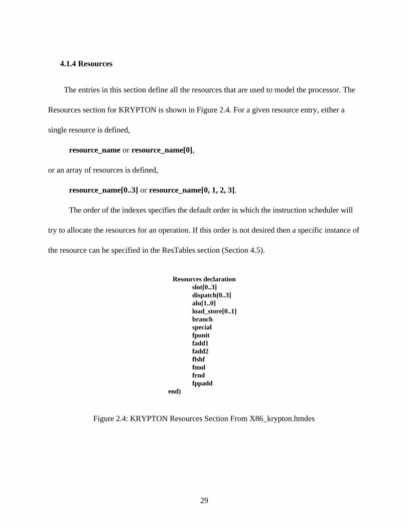
4.1.4 Resources
The entries in this section define all the resources that are used to model the processor. The
Resources section for KRYPTON is shown in Figure 2.4. For a given resource entry, either a
single resource is defined,
resource_name or resource_name[0],
or an array of resources is defined,
resource_name[0..3] or resource_name[0, 1, 2, 3].
The order of the indexes specifies the default order in which the instruction scheduler will
try to allocate the resources for an operation. If this order is not desired then a specific instance of
the resource can be specified in the ResTables section (Section 4.5).
Resources declaration slot[0..3] dispatch[0..3] alu[1..0] load_store[0..1] branch special fpunit fadd1 fadd2 flshf fmul frnd fppadd
end)
Figure 2.4: KRYPTON Resources Section From X86_krypton.hmdes
29

The "slot" resource or array of resources is a required Resources entry. This Resources entry
defines the number of operations that may be scheduled in a cycle. For KRYPTON four
instructions can be executed per cycle as long as there are available resources.
4.1.5 ResTables
The entries is the ResTables section define how operations use resources over time. An
example of some ResTables declarations for KRYPTON is shown in Figure 2.5. Each ResTable
entry is composed of the entry's name and a list of resource usage entries:
name ((resource_usage_entry0) (resource_usage_entry1) (...)).
Each resource entry consist of a resource name with an optional set of indexes and a
resource usage start and stop time:
(name[index1..indexn] start..stop).
The [index1..indexn] may be omitted if the name does not refer to an array of resources, or
if any of the resources in that array may be used and should be attempted to be scheduled in the
default order. If a particular binding is required, an instance of the resource can be used.
The RL_IMul entry in Figure 2.5 requests two dispatch units and does not care which are
received. RL_IMUL_2 is another way of requesting two dispatch units.
The start and stop times are with respect to the cycle which the instruction leaves the
decoder(cycle zero). The .. stop may be omitted if the stop time is the same as the start time. This
is the case for all functional units that execute in one cycle.
30

RL_IMul ( # Integer Multiply (slot 0)
(dispatch[0..1] 0) (fpunit 0) (fmul 1) (fppadd 2) (frnd 3)
)RL_IMul_2 ( # Integer Multiply
(slot 0) (dispatch 0) (dispatch 0) (fpunit 0) (fmul 1) (fppadd 2) (frnd 3) )
Figure 2.5: KRYPTON Res_Tables Entries From X86_krypton.hmdes
4.1.6 Latencies
The entries in the Latencies section specify the cycle for which each register operand is
read(source, predicate or incoming sync operands) or written(destinations, or outgoing sync
operands). This information is used to calculate dependence distances for flow, anti-, output and
control dependences. Each Latencies entry is composed as follows:
name(exception latency(pred0..)(dest0..)(src0..) (sync_src0..)(sync_dest0..)).
All latencies that are not specified are assumed to be used at cycle zero. Typically, all source
registers are used at decode time (cycle zero), and all of the destination registers are written when
the instruction leaves the functional unit. At this time the X86 code generator does not use
information from sync_src, sync_dest or pred fields.
31
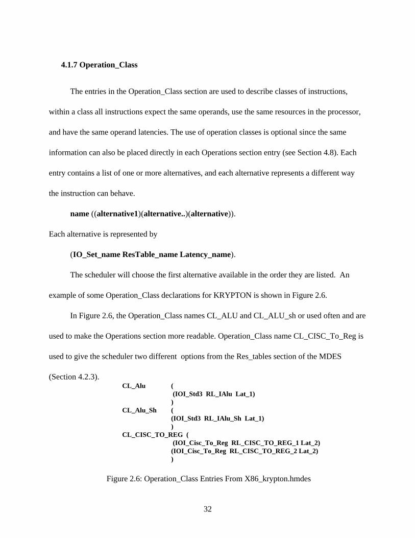
4.1.7 Operation_Class
The entries in the Operation_Class section are used to describe classes of instructions,
within a class all instructions expect the same operands, use the same resources in the processor,
and have the same operand latencies. The use of operation classes is optional since the same
information can also be placed directly in each Operations section entry (see Section 4.8). Each
entry contains a list of one or more alternatives, and each alternative represents a different way
the instruction can behave.
name ((alternative1)(alternative..)(alternative)).
Each alternative is represented by
(IO_Set_name ResTable_name Latency_name).
The scheduler will choose the first alternative available in the order they are listed. An
example of some Operation_Class declarations for KRYPTON is shown in Figure 2.6.
In Figure 2.6, the Operation_Class names CL_ALU and CL_ALU_sh or used often and are
used to make the Operations section more readable. Operation_Class name CL_CISC_To_Reg is
used to give the scheduler two different options from the Res_tables section of the MDES
(Section 4.2.3).CL_Alu (
(IOI_Std3 RL_IAlu Lat_1) )
CL_Alu_Sh ( (IOI_Std3 RL_IAlu_Sh Lat_1) )
CL_CISC_TO_REG ( (IOI_Cisc_To_Reg RL_CISC_TO_REG_1 Lat_2) (IOI_Cisc_To_Reg RL_CISC_TO_REG_2 Lat_2) )
Figure 2.6: Operation_Class Entries From X86_krypton.hmdes
32

4.1.8 Operations
The Operations section entries associate an operations opcode with opcode flags, assembly
name, assembly flags, and either an Operation_Class name or direct specification of scheduling
alternatives. An example of some Operations declarations for KRYPTON is shown in Figure 2.7.
The two possible forms are
name<opcode_flag0...>(assembly_name <assembly_flag0...>operation_class)
or
name<opcode_flag0...>(assembly_name <assembly_flag0...>(alternative0...)),
where each alternative has the form
(IO_Set_name ResTable_name Latency_name).
Lop_ASR (sar CL_Alu_Sh) Lop_ADD (add CL_Alu)
Lop_EQ (cmp CL_Cmp) Lop_EQ (cmp CL_Cmp_Set) Lop_MUL (imul ((IOI_Std3 RL_IMul Lat_imul)))
Lop_LD_UC <LOAD EXCEPT> (mov CL_LOAD_EX)
Figure 2.7: Operation Entries From X86_krypton.hmdes
The name specifies the opcode operation being described. Multiple entries with the same
name are used to specify different assembly names and/or assembly flags for different scheduling
alternatives.
The opcode_flags allow specific opcode information to be specified. This additional
information is defined in a C header file.
The assembly_name and assembly_flags are not supported by the X86 code generator.
The Operation_class is explained in Section 4.1.7.
33
4.2 KRYPTON MDES
KRYPTON presented three unique modeling problems. Section 4.2.1 describes the
problem of modeling the different alus and ensuring the correct one was chosen. Section 4.2.2
describes the problem of modeling the interaction between MROM and FAST instructions.
Section 4.2.3 describes the problem of modeling X86 instructions that contain two or three ROPs.
4.2.1 Alu selection
The alu selection problem is difficult for three reasons. First, both alus in KRYPTON can
both perform arithmetic and logical operations while ALU0 also performs shift and rotate
operations. Second, if a shift or rotate function and an arithmetic or logical function are decoded
and both alus are available, the logic ensures the ALU0 is selected properly. Third, except for the
last selection method, alus are allocated using a "last-used" method. This method selects the alu
that was not "last-used" when both alus are available.
Figure 2.4 gives all the resources defined by the KRYPTON MDES. The declaration of
alu[1..0] entry is used to take advantage of the default order and maintain consistency with
AMD's method of naming alus. A declaration of alu[0..1] would have also taken advantage of the
default order but would not have been consistent with AMD's method. Using either method, the
scheduler will choose the first alu in the index when both are available.
To ensure that the shift or rotate instruction uses ALU0 (alu[0]), a ResTables declaration
of RL_IAlu_sh is declared as shown in Figure 2.8. All shift and rotate instruction use this
ResTable declaration. This forces the scheduler to use ALU0. A second ResTables declaration of
34

RL_IAlu is declared as shown in Figure 2.9. All logical and arithmetic operations use this
declaration. This allows the scheduler two alu options: By default, ALU1 is chosen. If it is not
available, ALU0 is chosen.
This solves the first two problems. First, if a shift operation is encountered, it is scheduled
if and only if ALU0 is available. Second, if a logical or arithmetic operation is followed by a shift
or rotate operation, and both alus are available, then the logical or arithmetic operation uses
ALU1 and the shift or rotate operation uses ALU0.
The third problem cannot be modeled without a change to the MDES. The modeling
chosen always forces a use of ALU1 if both alus are available. This ensures that a shift or rotate
instruction can always execute if both alus are available. KRYPTON chooses alus based on the
"last-used" method and could send an arithmetic or logical operation to ALU0 if both are
available.
This creates a problem only if this operation is stalled because it is waiting for a TAG. This
will actually cause a stall in the processor if the next instruction is a shift or rotate instructions.
RL_IAlu_Sh ( # alu or shift op (slot 0) (dispatch 0)
(alu[0] 0) )
RL_IAlu ( # alu_op (slot 0) (dispatch 0) (alu 0)
)
Figure 2.8: ALU ResTable Declarations
35

4.2.2 FAST and MROM interaction
Section 3.1 briefly discussed the instruction decode logic used in KRYPTON. If an
instruction is encountered that is decoded by the MROM unit, its ROPs cannot be issued with
FAST ROPS. Figure 3.2 illustrates this.
The return instruction is an example of a MROM instruction even though it only contains
two ROPs. Its ResTable declaration is shown in Figure 2.9. By using all four dispatch instances
this instruction will not be issued until the previous FAST ROPs have been issued, and no FAST
ROPs can be issued with it. The MROM cannot issue until the FAST ROPs are complete because
it needs all four dispatch units. Likewise, FAST ROPs cannot issue until the MROM ROPs are
complete because it is using all four dispatch units.
MROM instructions with 5-8 ROPS must use four dispatch instances in cycle 0 and four
dispatch positions in cycle 1.
RL_Ret ( # Return micro-code that is why I use 4 dispatch(slot 0)
(dispatch 0) (dispatch 0) (dispatch 0) (dispatch 0)
(load_store 0)(alu 0)(branch 1))
Figure 2.9: Return ResTable Declaration
4.2.3 Two and three ROP instructions
All X86 instructions are decoded into at least one ROP. Some instructions that are used in
the X86 code generator are decoded into two or three ROPs. The problem of modeling these
36

instructions is that while these ROPs are decoded together, they may be issued across cycle
boundaries.
This problem is illustrated using two commonly used operations. The first X86 instruction
adds 2 to a memory location and is in the following form:
X86 instruction = MEM <- MEM +2,
which represents three KRYPTON ROPS,
ROP1 = TEMP_REG1 <- MEM,
ROP2 = TEMP_REG1 <- TEMP_REG1 + 2,
ROP3 = MEM <- TEMP_REG1.
Similarly, the second X86 instruction performs an addition between an X86 register and a
memory location and stores the result in the X86 register. It is in the following form:
X86 instruction = EAX <- EAX + MEM,
which represents two KRYPTON ROPS,
ROP1 = TEMP_REG1 <- MEM,
ROP2 = EAX <- EAX + TEMP_REG1.
In each case, more than one dispatch position is needed in cycle 0 to issue all the ROPs in
cycle 0. The number of dispatch positions required equals the number of ROPs. The first
instruction can be issued three different ways and the second instruction can be issued two
different ways. This depends on the number of dispatch positions available in cycle 0. Figure 2.10
shows the possible alternatives for the first instruction.
37
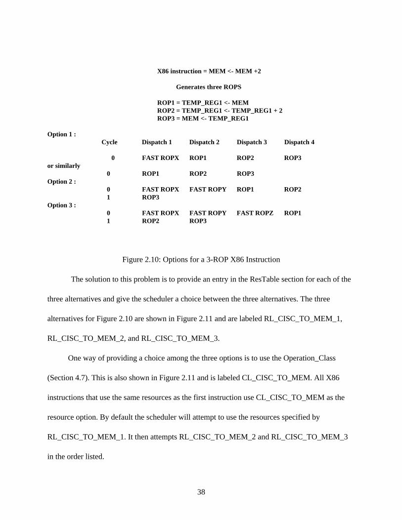
X86 instruction = MEM <- MEM +2
Generates three ROPS
ROP1 = TEMP_REG1 <- MEM ROP2 = TEMP_REG1 <- TEMP_REG1 + 2 ROP3 = MEM <- TEMP_REG1
Option 1 : Cycle Dispatch 1 Dispatch 2 Dispatch 3 Dispatch 4
0 FAST ROPX ROP1 ROP2 ROP3or similarly
0 ROP1 ROP2 ROP3 Option 2 : 0 FAST ROPX FAST ROPY ROP1 ROP2
1 ROP3Option 3 :
0 FAST ROPX FAST ROPY FAST ROPZ ROP1 1 ROP2 ROP3
Figure 2.10: Options for a 3-ROP X86 Instruction
The solution to this problem is to provide an entry in the ResTable section for each of the
three alternatives and give the scheduler a choice between the three alternatives. The three
alternatives for Figure 2.10 are shown in Figure 2.11 and are labeled RL_CISC_TO_MEM_1,
RL_CISC_TO_MEM_2, and RL_CISC_TO_MEM_3.
One way of providing a choice among the three options is to use the Operation_Class
(Section 4.7). This is also shown in Figure 2.11 and is labeled CL_CISC_TO_MEM. All X86
instructions that use the same resources as the first instruction use CL_CISC_TO_MEM as the
resource option. By default the scheduler will attempt to use the resources specified by
RL_CISC_TO_MEM_1. It then attempts RL_CISC_TO_MEM_2 and RL_CISC_TO_MEM_3
in the order listed.
38

RL_CISC_TO_MEM_1 ( # MEM <- MEM alu_op X SEE CL option 1 (slot 0) (dispatch[0..2] 0
(load_store[0..1] 0) (alu 1) )
RL_CISC_TO_MEM_2 ( # MEM <- MEM alu_op X SEE CL option 2 (slot 0) (dispatch[0..1] 0) (load_store 0)
(load_store 1) (dispatch 1) (alu 1)
)RL_CISC_TO_MEM_3 ( # MEM <- MEM alu_op X SEE CL option 3
(slot 0) (dispatch 0)
(load_store 0) (dispatch[0..1] 1)
(load_store 1)(alu 1)
)
CL_CISC_TO_MEM ((IOI_Cisc_To_Mem RL_CISC_TO_MEM_1 Lat_2)
(IOI_Cisc_To_Mem RL_CISC_TO_MEM_2 Lat_2) (IOI_Cisc_To_Mem RL_CISC_TO_MEM_3 Lat_2) )
Figure 2.11: 3-ROP Scheduling Solution
Similarly, two options exist for the second instruction based on the number of dispatch positions
available in cycle 0.
39

5. INSTRUCTION SELECTION
A major problem in generating code for KRYPTON is register pressure. Many
optimizations that generally work well for superscalar processors just do not work well for
KRYPTON.
An example of this is loop invariant code removal. This optimization moves code outside
the loop body that is not loop dependent. In theory it can reduce the cycle count by the number
of iterations of the loop. However, it also increases the variable lifetime and consequently the
register pressure. If this happens, a spill and a fill instruction can be generated by the register
allocator. This cancels the effect of the optimization and also adds additional instructions that
can decrease performance. Another example is loop unrolling. This optimization reduces the
number of iterations of a loop and expands it. This expansion generally causes an increase in
40

registers, which also increases register pressure. This in turn can increase the number of spill and
fill instructions.
This is not a problem for a typical superscalar processor with a large register file.
However, the X86 architecture provides only eight registers, and, generally, any optimization
that increases either the variable lifetime or the number of registers used does not work well on
KRYPTON.
Figure 5.1 shows the limitation of KRYPTON's small register file on IMPACT. The
benchmarks were scheduled using the KRYPTON MDES that was developed in the previous
chapter.
Benchmark Cycle Time Cycle Time Loss X86 REG NO REG
022.li 59826274 55919424 7.0%023.eqntott 8878206 8377315 5.9%072.sc 53265761 45195802 17.8%008.espresso 28463477 25414404 11.9%026.compress 27197622 22732987 19.6%
Figure 5.1 X86 Register File Limitations
These benchmark programs were scheduled two ways. The first column shows the
scheduling results using the X86 register file. The compilation path was varied using as many
"smart" optimizations as possible. The result is the fastest schedule. This cycle count is
calculated by using profile and scheduling information.
The second column shows the results of the same experiment using an infinite register
file. This was accomplished by turning the register allocator off. The third column shows the
slowdown caused by the spill and fill instructions.
41
This section discusses three optimizations that were developed to reduce register pressure.
These optimizations were not designed to directly reduce raw cycle count and in some cases to
trade-off increased cycle count for reduced register pressure. They were designed to reduce the
number of fill and spill instructions. Reducing the number of fill and spill instructions reduces
the total cycle count. Sections 3.1, 3.2 and 3.3 discuss these optimizations, which all use
memory variables instead of register variables. Section 3.4 gives the results of these
optimizations.
5.1 Arithmetic and Logical Operations Using Only Memory Variables
This section explains an optimization that uses memory variables instead of register
variables. The optimization searches for a pattern of the following : load X86_REGISTER from
a MEMORY_LOCATION, perform an arithmetic or logical operation on X86_REGISTER storing
the result into X86_REGISTER, and store X86_REGISTER into MEMORY_LOCATION. This
pattern is converted to one arithmetic or logical operation on MEMORY_LOCATION . An
example of such an X86 instruction pattern is
X86_REGISTER <- MEMORY_LOCATION (load),
X86_REGISTER <- X86_REGISTER+ 2 (arithmetic operation), and
MEMORY_LOCATION <- X86_REGISTER (store).
This sequence of instructions maps directly into three ROPs. It can also be represented by the
following X86 instruction:
MEMORY_LOCATION <- MEMORY_LOCATION + 2 (arithmetic operation) .
42

Instructions in this form are given the name CISC_TO_MEM. This instruction generates three
ROPs:
1.) TEMP_REG <- MEMORY_LOCATION,
2.) TEMP_REG <- TEMP_REG +2, and
3.) MEMORY_LOCATION <- TEMP_REG.
Two advantages exist in the CISC_TO_MEM instruction. First, one less register is used,
which can reduce register pressure, which in turn can reduce the number of register spills and
fills. Second, Krypton will always issue and execute the load and store in cycle one and the add
in cycle two if the resources are available. The load-op-store sequence of X86 instructions will
execute exactly as the CISC_TO_MEM instruction if the three instructions are scheduled as
shown. Because of scheduling, this is not always the case, and the store may take an extra cycle
to execute. The exact resource usage for a CISC_TO_MEM instruction is shown in Figure 5.2. It
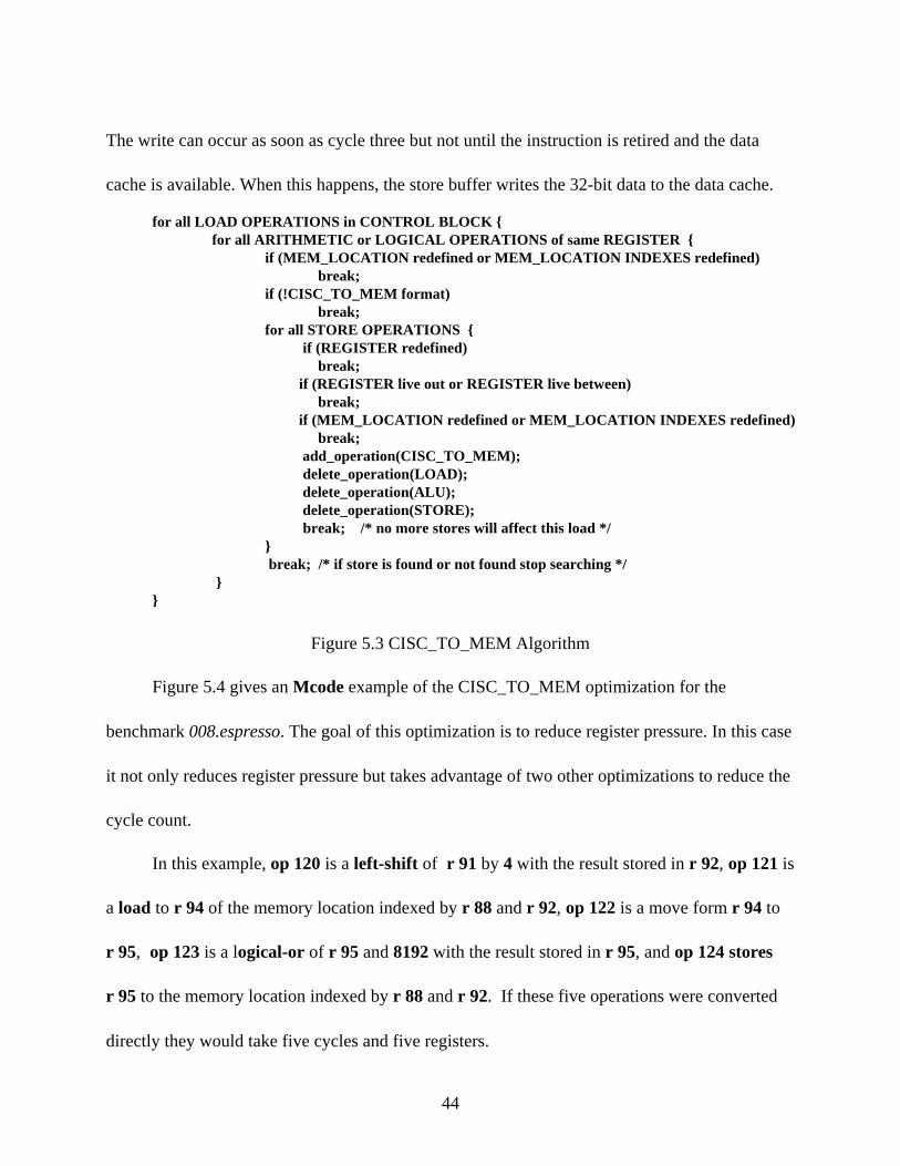
is taken from the KRYPTON MDES. The algorithm developed for this optimization is shown in
Figure 5.3.
RL_CISC_TO_MEM_1 ( # MEM <- MEM alu_op {REG or Immediate} (slot 0) (dispatch 0..3) (load_store 0) (load_store 0) (alu 1) )
Figure 5.2 CISC_TO_MEM Resource Usage
A CISC_TO_MEM instruction takes only two cycles. This happens because the store
operation is done as a read-modify-write operation. The read is done in the same cycle as the
load. The modify will occur at the end of cycle two, with the result forwarded to the store buffer.
43
The write can occur as soon as cycle three but not until the instruction is retired and the data
cache is available. When this happens, the store buffer writes the 32-bit data to the data cache.
for all LOAD OPERATIONS in CONTROL BLOCK { for all ARITHMETIC or LOGICAL OPERATIONS of same REGISTER { if (MEM_LOCATION redefined or MEM_LOCATION INDEXES redefined) break; if (!CISC_TO_MEM format) break; for all STORE OPERATIONS { if (REGISTER redefined) break; if (REGISTER live out or REGISTER live between) break; if (MEM_LOCATION redefined or MEM_LOCATION INDEXES redefined) break; add_operation(CISC_TO_MEM);
delete_operation(LOAD); delete_operation(ALU); delete_operation(STORE);
break; /* no more stores will affect this load */ } break; /* if store is found or not found stop searching */ } }
Figure 5.3 CISC_TO_MEM Algorithm
Figure 5.4 gives an Mcode example of the CISC_TO_MEM optimization for the
benchmark 008.espresso. The goal of this optimization is to reduce register pressure. In this case
it not only reduces register pressure but takes advantage of two other optimizations to reduce the
cycle count.
In this example, op 120 is a left-shift of r 91 by 4 with the result stored in r 92, op 121 is
a load to r 94 of the memory location indexed by r 88 and r 92, op 122 is a move form r 94 to
r 95, op 123 is a logical-or of r 95 and 8192 with the result stored in r 95, and op 124 stores
r 95 to the memory location indexed by r 88 and r 92. If these five operations were converted
directly they would take five cycles and five registers.
44

Two optimizations are performed to eliminate op 120 and op 122. The first optimization
converts op 120 and op 121 into a new op 121 and modifies op 124. This optimization takes
advantage of the X86 instruction LEA (load effective address). The second optimization
combines the new op 121 and op 122 into a new op 121. This pattern of three instructions takes
two or three cycles to execute and uses three registers.
These three operations are now converted from the load-logical operation-store format to
the CISC_TO_MEM format. This instruction now takes two cycles to execute and uses only
two registers.
Mcode before optimization
op 120 lsl [(r 92 i)] [()()(r 91 i)(i 4)]op 121 ld_i [(r 94 i)] [()(r 88 i)(r 92 i)]op 122 mov [(r 95 i)] [(r 94 i)])op 123 or [(r 95 i)] [(r 95 i)(i 8192)])op 124 st_i [] [(r 95 i)(r 88 i)(r 92 i)]
Mcode after LEA and REVERSE_COPY_PROPAGATION optimizations
op 121 ld_i [(r 95 i)] [()(r 88 i)(r 91 i)(i 4)]op 123 or [(r 95 i)] [(r 95 i)(i 8192)])op 124 st_i [] [(r 95 i)(r 88 i)(r 91 i)(i4)]
Mcode after CISC_TO_MEM optimization
op 124 or [] [(i 8192)(r 88 i)(r 91 i)(i 4)]
Figure 5.4 Example Optimization from 008.espresso f_161
5.2 Arithmetic and Logical Operations Using Register and Memory Variables
This section explains another optimization that uses memory variables. In this case the
memory variable is only a source operand. The optimization searches for a pattern of the
following: load X86_REGISTER from a MEMORY_LOCATION, and perform an arithmetic or
45

logical operation using X86_REGISTER as a source operand. This pattern is converted to an
arithmetic or logical operation with the memory location as a source operand. An example of
such a X86 instruction pattern is
X86_REGISTER_A <- MEMORY_LOCATION (load), and
X86_REGISTER _B <- X86_REGISTER_B + X86_REGISTER_A (arithmetic operation).
This sequence of instructions maps directly into two ROPs. It can also be represented by the
following X86 instruction:
X86_REGISTER <- X86_REGISTER + MEMORY_LOCATION .
Instructions in this form are given the name CISC_TO_REG. This instruction generates two
ROPs:
1.) TEMP_REG <- MEMORY_LOCATION, and
2.) X86_REGISTER <- X86_REGISTER + TEMP_REG.
Both set of instructions are treated the same by KRYPTON . The first option maps
directly into two ROPs; the second is decoded into two ROPs. Both methods take two cycles to
execute on KRYPTON. The exact resource usage for a CISC_TO_REG is shown Figure 5.6.
RL_CISC_TO_REG_1 ( # REG <- REG alu_op MEM SEE CL option 1 (slot 0)
(dispatch 0) (dispatch 0) (load_store 0) (alu 1) )
Figure 5.6: CISC_TO_REG Resource Usage
46

One advantage of the second instruction is that one less register is used, which can reduce
register pressure, which in turn can reduce the number of register spills and fills. Another
advantage occurs when the load is a load sign extend or load zero extend. If this is the case, the
first method actually generates three ROPS while the second case always generates two ROPS.
A load sign extend or load zero extend is an 8-bit or 16-bit load into a 32-bit register with
the sign or zeroes extended across the 32-bit register. Using the zero extended load as an
example, the three cycles are explained. In the first cycle, the register is cleared. This takes one
ROP, one cycle and an alu. In the second cycle, the load is performed. This takes one ROP, one
cycle and a load/store unit. In the third cycle, the addition is performed. This takes one ROP, one
cycle and an alu. The exact resource usage of an extended load followed by an add is shown in
Figure 5.7.
If this extended load followed by an arithmetic or logical operation is converted to a
CISC_TO_REG operation, the resource usage is the same as Figure 5.6. In this case the
optimization not only saves a register but also saves one cycle.
RL_Load_Ex_1 ( # byte/word/double load option #1 (slot 0)
(dispatch 0) (dispatch 0) (load_store 0) (alu 1) )
followed by
RL_IAlu ( # alu_op SEE CL (slot 0) (dispatch 0) (alu 0) )
Figure 5.7: Extended Load Followed by an Alu_op
47

This optimization searches for up to three uses of the load, and if they can all be converted to
CISC_TO_REG it converts them. If this is the case, a trade-off of cycle time is made to reduce
register pressure.
The algorithm developed for this optimization is shown in Figure 5.8.
for all LOAD OPERATIONS in CONTROL BLOCK { for all ARITHMETIC or LOGICAL OPERATIONS of same REGISTER { if(!CISC_TO_REG format) break; if(can't_cisc_all_uses) break; if(redefined_between_load_and_last_use(MEM_LOCATION))
break; if(redefined_between_load_and_last_use(MEM_LOCATION_INDEXES))
break; if(live_out(REGISTER)) break; add_operation(CISC_TO_REG);
delete_operation(LOAD); delete_operation(ALU);
break;}
}
Figure 5.8 CISC_TO_REG Algorithm
5.3 Compare Instructions Using Memory Variables
This section explains the last optimization that uses memory variables. In this case the
memory variable is only a source operand, and the operation is a compare. The optimization
searches for a pattern of the following: load X86_REGISTER from a MEMORY_LOCATION,
and perform a compare between X86_REGISTER and another operand. This pattern is
converted to a compare between the memory location and another operand. An example of such
an X86 instruction pattern is
X86_REGISTER<- MEMORY_LOCATION (load), and
48

compare X86_REGISTER, 1 (compare operation).
This sequence of instructions maps directly into two ROPs. It can also be represented by the
following X86 instruction:
compare MEMORY_LOCATION , 1.
Instructions in this form are given the name CISC_COMPARE. This instruction generates two
ROPs:
1.) TEMP_REG <- MEMORY_LOCATION, and
2.) compare TEMP_REG, 1.
Both set of instructions are treated the same by KRYPTON . The first option maps
directly into two ROPs; the second one is decoded into two ROPs. Both methods take two cycles
to execute on KRYPTON.
The thing that distinguishes this optimization is the load-compare pattern is actually a
Mcode load-compare_and_branch pattern.. This compare and branch instruction is modified and
broken down to a separate compare and branch in a different step.
This optimization has the same advantages as the CISC_TO_REG to and also searches for
up to three uses of the load and converts them to CISC_COMPARE operations. Again, a trade-
off is made between cycle time and register pressure. The algorithm developed for this
optimization is shown in Figure 5.9.
49

for all LOAD OPERATIONS in CONTROL BLOCK { for all COMPARE_AND_BRANCH OPERATIONS of same REGISTER { if(!CISC_COMPARE format) break;
if(uses(REGISTER) > 3) break; if(can't_cisc_all_uses) break; if(redefined_between_load_and_last_use(MEM_LOCATION))
break; if(redefined_between_load_and_last_use(MEM_LOCATION_INDEXES)) break; if(live_out(REGISTER)) break; annotate_operation(CISC_TO_REG);
delete_operation(LOAD); break;
} }
Figure 5.9 CISC_COMPARE Algorithm
5.4 Results
Figure 5.10 shows the results of the optimizations on cycle time. The seven columns are
the seven combinations of optimizations. Each column heading corresponds to a combination.
The first on or off represents the CISC_TO_MEM optimization. The second on or off represents
the CISC_TO_REG optimization. The third on or off represents the CISC_COMPARE
optimization. All numbers are percent speed-up over the benchmarks with all optimizations off.
Benchmark off off on off on off off on on on off off on off on on on off on on on
022.li 0.98 0.00 0.98 1.19 0.47 1.19 0.47 023.eqntott 1.40 1.21 1.05 0.00 1.42 1.21 1.05
072.sc 0.18 0.00 0.18 1.49 1.67 1.49 1.67 008.espresso 0.13 0.17 2.14 7.38 2.03 5.65 3.58 026.compress 11.76 3.92 16.50 12.06 16.05 13.03 17.46
Figure 5.10 Optimization Results
50

As expected, the largest speed-up happens in the 026.compress benchmark . This is the
benchmark with the most spill and fill instructions. Certain combinations of optimizations
actually perform worse than does a single optimization. This is mainly due to the heuristics used
in the register allocator. However, the best overall result occurs with all the optimizations turned
on.
51

6. CONCLUSIONS
This thesis has described the changes made to the X86 code generator to support AMD's
KRYPTON microprocessor. Code has been scheduled using the KRYPTON MDES and the
memory variable optimizations. This code has been tested on both 486 and Pentium machines.
The scheduling information has been analyzed and feedback has been provided to enhance the
IMPACT register allocator and scheduler. The "CISC" optimizations have been shown to increase
overall performance by reducing register pressure.
Future work includes comparing scheduling results with a KRYPTON simulator provided
by AMD. It also includes verifying the results on a machine with a KRYPTON processor. The
simulator can provide insight to enhance the MDES, and will show the instructions dispatch, issue
and completion. Comparisons can be made with the scheduled code, and changes to the MDES
may be necessary.
52

REFERENCES
[1] J. C. Gyllenhaal, "A machine description language for compilation," M.S. thesis, Universityof Illinois, Urbana, IL, 1994.
[2] R. A. Bringmann, "Template for code generation development using the IMPACT-I Ccompiler," M.S. thesis, University of Illinois, Urbana, IL, 1992.
[3] W. W. Hwu, S. A. Mahlke, W. Y. Chen, P. P. Chang, N. J. Warter, R. A. Bringmann, R. G.Ouellette, R. E. Hank, T. Kiyohara, G. E. Holm, and D. M. Lavery, "The Superblock: Aneffective technique for VLIW and superscalar compilation," The Journal of Supercomputing, vol.7, pp. 229-248, January 1993.
[4] W. M. Johnson, Superscalar Microprocessor Design. Englewood Cliffs, NJ: Prentice-Hall,Inc., 1991.
[5] P. P. Chang, S. A. Mahlke, W. Y. Chen, N. J. Warter, and W. W. Hwu, "IMPACT; Anarchitectural framework for multiple-instruction-issue processors," Proceedings of the 18thInternational Symposium on Computer Architecture, pp. 266-275, May 1991.
[6] R. M. Tomasulo, "An Efficient Algorithm for Exploiting Multiple Arithmetic Units," IBMJournal, vol. 11, pp. 25-33, January 1967.
[7] Intel Literture Sales, Pentium Family Users Manual. Intel Corporation, Inc., MountProspect, IL., 1995
[8] D. Witt, The KRYPTON Architecture Manual. AMD Inc., Austin, TX., 1994
53