Embed Size (px)
DESCRIPTION
Scheduling information
Citation preview
3GPP TS 32.425 V8.2.0 (2009-09)Technical Specification
3rd Generation Partnership Project;Technical Specification Group Services and System Aspects;
Telecommunication management;Performance Management (PM);
Performance measurementsEvolved Universal Terrestrial Radio Access Network
(E-UTRAN) (Release 8)
The present document has been developed within the 3rd Generation Partnership Project (3GPP TM) and may be further elaborated for the purposes of 3GPP. The present document has not been subject to any approval process by the 3GPP Organizational Partners and shall not be implemented. This Specification is provided for future development work within 3GPP only. The Organizational Partners accept no liability for any use of this Specification.Specifications and reports for implementation of the 3GPP TM system should be obtained via the 3GPP Organizational Partners' Publications Offices.
3GPP
KeywordsE-UTRAN, management, performance
3GPP
Postal address
3GPP support office address650 Route des Lucioles - Sophia Antipolis
Valbonne - FRANCETel.: +33 4 92 94 42 00 Fax: +33 4 93 65 47 16
Internethttp://www.3gpp.org
Copyright Notification
No part may be reproduced except as authorized by written permission.The copyright and the foregoing restriction extend to reproduction in all media.
© 2009, 3GPP Organizational Partners (ARIB, ATIS, CCSA, ETSI, TTA, TTC).All rights reserved.
UMTS™ is a Trade Mark of ETSI registered for the benefit of its members3GPP™ is a Trade Mark of ETSI registered for the benefit of its Members and of the 3GPP Organizational PartnersLTE™ is a Trade Mark of ETSI currently being registered for the benefit of its Members and of the 3GPP Organizational PartnersGSM® and the GSM logo are registered and owned by the GSM Association
3GPP TS 32.425 V8.2.0 (2009-09)2Release 8
Contents1 Scope.................................................................................................................................................9
2 References.........................................................................................................................................9
3 Measurement family and abbreviations..........................................................................................103.1 Measurement family..................................................................................................................................103.2 Abbreviations............................................................................................................................................10
4 Measurements related to eNodeB...................................................................................................114.1 RRC connection related measurements....................................................................................................114.1.1 RRC connection establishment............................................................................................................114.1.1.1 Attempted RRC connection establishments..................................................................................114.1.1.2 Successful RRC connection establishments..................................................................................114.1.1.3 Failed RRC connection establishments.........................................................................................124.1.2 RRC connection re-establishment.......................................................................................................124.1.2.1 Attempted RRC connection re-establishments..............................................................................124.1.2.2 Successful RRC connection re-establishments..............................................................................134.1.2.3 Failed RRC connection re-establishments.....................................................................................134.1.3 RRC connection number.....................................................................................................................134.1.3.1 Mean number of RRC Connections...............................................................................................134.1.3.2 Maximum number of RRC Connections.......................................................................................144.1.4 RRC connection setup time.................................................................................................................144.1.4.1 Mean RRC connection setup time.................................................................................................144.1.4.2 Maximum RRC connection setup time..........................................................................................144.2 SAE Bearer related measurements............................................................................................................154.2.1 SAE Bearer setup................................................................................................................................154.2.1.1 Number of initial SAE Bearers attempted to setup........................................................................154.2.1.2 Number of initial SAE Bearers successfully established...............................................................154.2.1.3 Number of initial SAE Bearers failed to setup..............................................................................164.2.1.4 Number of additional SAE Bearers attempted to setup.................................................................164.2.1.5 Number of additional SAE Bearers successfully established........................................................174.2.1.6 Number of additional SAE Bearers failed to setup........................................................................174.2.1.7 Mean SAE Bearer Setup time........................................................................................................174.2.1.8 Maximum SAE Bearer Setup time................................................................................................184.2.2 SAE Bearer release..............................................................................................................................184.2.2.1 Number of SAE Bearers requested to release initiated by eNodeB per QCI................................184.2.2.3 Number of SAE Bearers attempted to release...............................................................................194.2.2.4 Number of SAE Bearers successfully released..............................................................................194.2.2.5 Number of SAE Bearers failed to release......................................................................................204.2.2.6 Number of released active SAE Bearers........................................................................................204.2.3 SAE Bearer modification....................................................................................................................214.2.3.1 Number of SAE Bearers attempted to modify the QoS parameter................................................214.2.3.2 Number of SAE Bearers successfully modified the QoS parameter.............................................214.2.3.3 Number of SAE Bearers failed to modify the QoS parameter......................................................214.2.4 SAE Bearer activity.............................................................................................................................224.2.4.1 In-session activity time for UE......................................................................................................224.2.4.2 In-session activity time for SAE Bearers.......................................................................................224.3 Handover related measurements...............................................................................................................234.3.1 Intra-RAT Handovers..........................................................................................................................234.3.1.1 Intra-eNB Handover related measurements...................................................................................234.3.1.1.1 Attempted outgoing intra-eNB handovers per handover cause...............................................234.3.1.1.2 Successful outgoing intra-eNB handovers per handover cause...............................................234.3.1.2 Inter-eNB Handover related measurements...................................................................................244.3.1.2.1 Attempted outgoing inter-eNB handover preparations............................................................244.3.1.2.2 Attempted outgoing inter-eNB handovers per handover cause...............................................244.3.1.2.3 Successful outgoing inter-eNB handovers per handover cause...............................................244.3.1.3 Handover measurements on neighbour cell basis..........................................................................254.3.1.3.1 Attempted outgoing handovers per handover cause................................................................25
3GPP
3GPP TS 32.425 V8.2.0 (2009-09)3Release 8
4.3.1.3.1 Successful outgoing handovers per handover cause................................................................254.3.1.4 Intra- / Inter-frequency Handover related measurements..............................................................254.3.1.4.1 Attempted outgoing intra-frequency handovers.......................................................................254.3.1.4.2 Successful outgoing intra-frequency handovers......................................................................264.3.1.4.3 Attempted outgoing inter-frequency handovers – gap-assisted measurement.........................264.3.1.4.4 Successful outgoing inter-frequency handovers – gap-assisted measurement........................264.3.1.4.5 Attempted outgoing inter-frequency handovers – non gap-assisted measurement..................274.3.1.4.6 Successful outgoing inter-frequency handovers – non gap-assisted measurement.................274.3.1.5 Handover related measurements for DRX / non-DRX..................................................................274.3.1.5.1 Attempted outgoing handovers with DRX...............................................................................274.3.1.5.2 Successful outgoing handovers with DRX..............................................................................284.3.1.5.3 Attempted outgoing handovers non-DRX...............................................................................284.3.1.5.4 Successful outgoing handovers non-DRX...............................................................................284.3.2 Inter-RAT Handovers..........................................................................................................................294.3.2.1 Measurements related to inter-RAT Handovers – target cell of 3GPP and non-3GPP network
technology......................................................................................................................................294.3.2.1.1 Attempted outgoing inter-RAT handovers per handover cause...............................................294.3.2.1.2 Successful outgoing inter-RAT handovers per handover cause..............................................294.3.2.1.3 Failed outgoing inter-RAT handovers per failure cause..........................................................304.4 Cell level radio bearer QoS related measurements...................................................................................304.4.1 Cell PDCP SDU bit-rate......................................................................................................................304.4.1.1 Average DL cell PDCP SDU bit-rate............................................................................................304.4.1.2 Average UL cell PDCP SDU bit-rate............................................................................................314.4.1.3 Maximum DL cell PDCP SDU bit-rate.........................................................................................314.4.1.4 Maximum UL cell PDCP SDU bit-rate.........................................................................................324.4.1.5 Average DL cell control plane PDCP SDU bit-rate......................................................................324.4.1.6 Average UL cell control plane PDCP SDU bit-rate......................................................................324.4.2 Active UEs...........................................................................................................................................334.4.2.1 Average number of active UEs on the DL.....................................................................................334.4.2.2 Average number of active UEs on the UL.....................................................................................334.4.3 Packet Delay and Drop Rate................................................................................................................334.4.3.1 Average DL PDCP SDU delay......................................................................................................334.4.3.2 DL PDCP SDU drop rate...............................................................................................................344.4.4 Packet loss rate....................................................................................................................................344.4.4.1 DL PDCP SDU air interface loss rate............................................................................................344.4.4.2 UL PDCP SDU loss rate................................................................................................................344.4.5 IP Latency measurements....................................................................................................................354.4.5.1 IP Latency in DL, SAE Bearer level..............................................................................................354.5 Radio resource utilization related measurements......................................................................................364.5.1 DL PRB Usage for traffic....................................................................................................................364.5.2 UL PRB Usage for traffic....................................................................................................................364.5.3 DL Total PRB Usage...........................................................................................................................364.5.4 UL Total PRB Usage...........................................................................................................................374.5.5 RACH Usage.......................................................................................................................................374.5.6 Cell Unavailable Time.........................................................................................................................374.6 UE-associated logical S1-connection related measurements....................................................................384.6.1 UE-associated logical S1-connection establishment...........................................................................384.6.1.1 Attempted UE-associated logical S1-connection establishment from eNB to MME....................384.6.1.2 Succesful UE-associated logical S1-connection establishment from eNB to MME.....................384.7 Paging related measurements....................................................................................................................394.7.1 Paging Performance.............................................................................................................................394.7.1.1. Number of paging records discarded at the eNodeB.....................................................................39
3GPP
3GPP TS 32.425 V8.2.0 (2009-09)4Release 8
Annex A (informative): Use cases for performance measurements defintion..........................40
A.1 Monitor of call(/session) setup performance...................................................................................40
A.2 Monitor of SAE Bearer release.......................................................................................................40
A.3 Monitor of SAE Bearer level QoS modification.............................................................................41
A.4 Overview handover related Use Cases............................................................................................41
A.5 Monitor of cell level QoS and radio resource utilisation................................................................42
A.6 Monitor of the number of connected users.....................................................................................44
A.7 Monitoring of interference situation...............................................................................................44
A.8 Monitor of ARQ and HARQ performance......................................................................................44
A.9 Monitor of RF performance............................................................................................................45
A.10 Monitor of paging performance......................................................................................................45
Annex B (informative): Change history.........................................................................................46
3GPP
3GPP TS 32.425 V8.2.0 (2009-09)5Release 8
ForewordThis Technical Specification has been produced by the 3rd Generation Partnership Project (3GPP).
The contents of the present document are subject to continuing work within the TSG and may change following formal TSG approval. Should the TSG modify the contents of the present document, it will be re-released by the TSG with an identifying change of release date and an increase in version number as follows:
Version x.y.z
where:
x the first digit:
1 presented to TSG for information;
2 presented to TSG for approval;
3 or greater indicates TSG approved document under change control.
y the second digit is incremented for all changes of substance, i.e. technical enhancements, corrections, updates, etc.
z the third digit is incremented when editorial only changes have been incorporated in the document.
IntroductionThe present document is part of a TS-family covering the 3rd Generation Partnership Project; Technical Specification Group Services and System Aspects; Telecommunication management; as identified below:
32.401 Performance Management (PM); Concept and requirements
52.402 Performance Management (PM); Performance measurements – GSM
32.404 Performance Management (PM); Performance measurements - Definitions and template
32.405 Performance Management (PM); Performance measurements Universal Terrestrial Radio Access Network (UTRAN)
32.406 Performance Management (PM); Performance measurements Core Network (CN) Packet Switched (PS) domain
32.407 Performance Management (PM); Performance measurements Core Network (CN) Circuit Switched (CS) domain
32.408 Performance Management (PM); Performance measurements Teleservice
32.409 Performance Management (PM); Performance measurements IP Multimedia Subsystem (IMS)
32.425 Performance Management (PM); Evolved Performance measurements Universal Terrestrial Radio Access Network (E-UTRAN)
32.426 Performance Management (PM); Evolved Packet Core (EPC)
The present document is part of a set of specifications, which describe the requirements and information model necessary for the standardised Operation, Administration and Maintenance (OA&M) of a multi-vendor E-UTRAN and EPC system.
During the lifetime of an E-UTRAN, its logical and physical configuration will undergo changes of varying degrees and frequencies in order to optimise the utilisation of the network resources. These changes will be executed through network configuration management activities and/or network engineering, see TS 32.600 [3].
3GPP
3GPP TS 32.425 V8.2.0 (2009-09)6Release 8
Many of the activities involved in the daily operation and future network planning of an E-UTRAN require data on which to base decisions. This data refers to the load carried by the network and the grade of service offered. In order to produce this data performance measurements are executed in the NEs, which comprise the network. The data can then be transferred to an external system, e.g. an Operations System (OS) in TMN terminology, for further evaluation. The purpose of the present document is to describe the mechanisms involved in the collection of the data and the definition of the data itself.
Annex B of TS 32.404 helps in the definition of new performance measurements that can be submitted to 3GPP for potential adoption and inclusion in the present document. Annex B of TS 32.404 discusses a top-down performance measurement definition methodology that focuses on how the end-user of performance measurements can use the measurements.
3GPP
3GPP TS 32.425 V8.2.0 (2009-09)7Release 8
1 ScopeThe present document describes the measurements for E-UTRAN.
TS 32.401 [5] describes Performance Management concepts and requirements.
The present document is valid for all measurement types provided by an implementation of an E-UTRAN.
Only measurement types that are specific to E-UTRAN are defined within the present documents. Vendor specific measurement types used in E-UTRAN are not covered. Instead, these could be applied according to manufacturer's documentation.
Measurements related to "external" technologies (such as ATM or IP) as described by "external" standards bodies (e.g. ITU-T or IETF) shall only be referenced within this specification, wherever there is a need identified for the existence of such a reference.
The definition of the standard measurements is intended to result in comparability of measurement data produced in a multi-vendor network, for those measurement types that can be standardised across all vendors' implementations.
The structure of the present document is as follows:
- Header 1: Network Element (e.g. measurements related to eNodeB);
- Header 2: Measurement function (e.g. RRC connection setup related measurements);
- Header 3: Measurements.
2 ReferencesThe following documents contain provisions which, through reference in this text, constitute provisions of the present document.
References are either specific (identified by date of publication and/or edition number or version number) or non-specific.
For a specific reference, subsequent revisions do not apply.
For a non-specific reference, the latest version applies. In the case of a reference to a 3GPP document (including a GSM document), a non-specific reference implicitly refers to the latest version of that document in the same Release as the present document.
[1] 3GPP TS 32.101: "Telecommunication management; Principles and high level requirements".
[2] 3GPP TS 32.102: "Telecommunication management; Architecture".
[3] 3GPP TS 32.600: "Telecommunication management; Configuration Management (CM); Concept and high-level requirements".
[5] 3GPP TS 32.401: "Telecommunication management; Performance Management (PM); Concept and requirements".
[6] 3GPP TS 32.404: "Performance Management (PM); Performance measurements - Definitions and template".
[7] 3GPP TS 32.762: "Evolved Universal Terrestrial Radio Access Network (E-UTRAN) Network Resource Model (NRM) Integration Reference Point (IRP): Information Service (IS)".
[8] 3GPP TS 36.331: "Evolved Universal Terrestrial Radio Access (E-UTRA); Radio Resource Control (RRC) protocol specification".
[9] 3GPP TS 36.413: "Evolved Universal Terrestrial Access Network (E-UTRAN); S1 Application Protocol (S1AP)".
3GPP
3GPP TS 32.425 V8.2.0 (2009-09)8Release 8
[10] 3GPP TS 36.423: "Evolved Universal Terrestrial Radio Access Network (EUTRAN); X2 application protocol (X2AP)".
[11] TS 36.314, “Evolved Universal Terrestrial Radio Access (E-UTRA); Layer 2 – Measurements (Release 8)”
[12] TS 36.300, “Evolved Universal Terrestrial Radio Access (E-UTRA); and Evolved Universal Terrestrial Radio Access Network (E-UTRAN); Overall description; Stage 2 (Release 8)”
[13] 3GPP TS 32.450 Telecommunication management; Key Performance Indicators (KPI) for E-UTRAN: Definitions (Release 8)
[14] 3GPP TS 36.304, “Evolved Universal Terrestrial Radio Access (E-UTRA); User Equipment (UE) procedures in idle mode”
3 Measurement family and abbreviations
3.1 Measurement familyThe measurement names defined in the present document are all beginning with a prefix containing the measurement family name (e.g. RRC.AttConnEstab.Cause). This family name identifies all measurements which relate to a given functionality and it may be used for measurement administration (see TS 32.401 [5]).
The list of families currently used in the present document is as follows:
- DRB (measurements related to Data Radio Bearer)- RRC (measurements related to Radio Resource Control)- RRU (measurements related to Radio Resource Utilization)- SAEB (measurements related to SAE Bearer)- HO (measurements related to Handover)- S1SIG (measurements related to S1 Signalling)- SRB (measurements related to Signalling Radio Bearer)- PAG (measurements related to Paging)
3.2 AbbreviationsFor the purposes of the present document, the following abbreviations apply:
3G 3rd Generation3GPP 3G Partnership ProjectEPS Evolved Packet SystemE-UTRAN Evolved UTRANHO HandoverQoS Quality of ServiceSAE System Architecture EvolutionUTRAN Universal Terrestrial Radio Access Network
You can find below a list of abbreviations used within the measurement types for field E of the measurement template (see 3GPP TS 32.404 [6]).
Alloc AllocationAtt Attempt(s,ed)Conn ConnectionDed DedicatedDL DownlinkENB eNodeBEstab Establish (ed,ment)Fail Fail(ed, ure) Freq FrequencyInc Incoming
3GPP
3GPP TS 32.425 V8.2.0 (2009-09)9Release 8
Out OutgoingPkt Packet(s)Prep Prepare(/Preparation)Late LatencyMod Modify(/Modification)Nbr NumberRel Release(s,d)Res ResourceSucc Success(es,ful)UL Uplink
4 Measurements related to eNodeB
4.1 RRC connection related measurements
4.1.1 RRC connection establishment
The three measurement types defined in the subclause 4.1.1.n are subject to the "2 out of 3 approach".
4.1.1.1 Attempted RRC connection establishments
a) This measurement provides the number of RRC connection establishment attempts for each establishment cause.
b) CC
c) Receipt of a RRC CONNECTION REQUEST message by the eNodeB from the UE. Each RRC Connection Request message received is added to the relevant per establishment cause measurement. The possible causes are included in TS 36.331 [8]. The sum of all supported per cause measurements shall equal the total number of RRC Connection Establishment attempts. In case only a subset of per cause measurements is supported, a sum subcounter will be provided first.
d) Each measurement is an integer value. The number of measurements is equal to the number of causes plus a possible sum value identified by the .sum suffix.
e) The measurement name has the form RRC.ConnEstabAtt.Causewhere Cause identifies the establishment cause.
f) EUtranCellFDDEUtranCellTDD
g) Valid for packet switched traffic
h) EPS
4.1.1.2 Successful RRC connection establishments
a) This measurement provides the number of successful RRC establishments for each establishment cause.
b) CC
c) Receipt by the eNodeB of a RRC CONNECTION SETUP COMPLETE message following a RRC connection establishment request. Each RRC CONNECTION SETUP COMPLETE message received is added to the relevant per establishment cause measurement. The possible causes are included in TS 36.331 [8]. The sum of all supported per cause measurements shall equal the total number of RRC Connection Establishments. In case only a subset of per cause measurements is supported, a sum subcounter will be provided first.
d) Each measurement is an integer value. The number of measurements is equal to the number of causes plus a possible sum value identified by the .sum suffix.
e) The measurement name has the form RRC.ConnEstabSucc.Causewhere Cause identifies the establishment cause.
3GPP
3GPP TS 32.425 V8.2.0 (2009-09)10Release 8
f) EUtranCellFDDEUtranCellTDD
g) Valid for packet switched traffic
h) EPS
4.1.1.3 Failed RRC connection establishments
a) This measurement provides the number of RRC establishment failures for each establishment cause.
b) CC
c) Transmission of an RRC CONNECTION REJECT message by the eNodeB to the UE or an expected RRC CONNECTION SETUP COMPLETE message not received by the eNodeB. Each failed RRC connection establishment is added to the relevant per establishment cause measurement. The possible causes are included in TS 36.331 [8].The sum of all supported per cause measurements shall equal the total number of RRC connection establishment failures. In case only a subset of per cause measurements is supported, a sum subcounter will be provided first.
d) Each measurement is an integer value. The number of measurements is equal to the number of causes plus a possible sum value identified by the .sum suffix.
e) The measurement name has the form RRC.ConnEstabFail.Causewhere Cause identifies the establishment cause.
f) EUtranCellFDDEUtranCellTDD
g) Valid for packet switched traffic
h) EPS
4.1.2 RRC connection re-establishment
The three measurement types defined in the subclause 4.1.2.n are subject to the "2 out of 3 approach".
4.1.2.1 Attempted RRC connection re-establishments
a) This measurement provides the number of RRC connection re-establishment attempts for each re-establishment cause.
b) CC.
c) Receipt of a RRCConnectionReestablishmentRequest message by the eNodeB from the UE. Each RRCConnectionReestablishmentRequest received is added to the relevant per reestablishment cause measurement. The possible causes are included in TS 36.331 [8]. The sum of all supported per cause measurements shall equal the total number of RRC connection re-stablishment attempts. In case only a subset of per cause measurements is supported, a sum subcounter will be provided first.
d) Each measurement is an integer value. The number of measurements is equal to the number of causes plus a possible sum value identified by the .sum suffix.
e) The measurement name has the form RRC.ConnReEstabAtt.Causewhere Cause identifies the reestablishment cause.
f) EUtranCellFDDEUtranCellTDD
g) Valid for packet switching.
h) EPS
3GPP
3GPP TS 32.425 V8.2.0 (2009-09)11Release 8
4.1.2.2 Successful RRC connection re-establishments
a) This measurement provides the number of successful RRC connection re-establishments for each re-establishment cause.
b) CC.
c) Receipt by the eNodeB of a RRCConnectionReestablishmentComplete message following a RRC connection reestablishment request. Each RRCConnectionReestablishmentComplete message received is added to the relevant per reestablishment cause measurement. The possible causes are included in TS 36.331 [8]. The sum of all supported per cause measurements shall equal the total number of successful RRC connection re-establishments. In case only a subset of per cause measurements is supported, a sum subcounter will be provided first.
d) Each measurement is an integer value. The number of measurements is equal to the number of causes plus a possible sum value identified by the .sum suffix.
e) The measurement name has the form RRC.ConnReEstabSucc.Causewhere Cause identifies the establishment cause.
f) EUtranCellFDDEUtranCellTDD
g) Valid for packet switching.
h) EPS
4.1.2.3 Failed RRC connection re-establishments
a) This measurement provides the number of RRC re-establishment failures for each re-establishment cause.
b) CC.
c) Transmission of an RRCConnectionReestablishmentReject message by the eNodeB to the UE or an expected RRCConnectionReestablishmentComplete message not received by the eNodeB. Each failed RRC connection re-establishment is added to the relevant per re-establishment.cause measurement. The possible causes are included in TS 36.331 [8].The sum of all supported per cause measurements shall equal the total number of RRC connection re-establishment failures. In case only a subset of per cause measurements is supported, a sum subcounter will be provided first.
The measurement name has the form RRC.ConnReEstabFail.Causewhere Cause identifies the re-establishment.cause.
d) EUtranCellFDDEUtranCellTDD
e) Valid for packet switching.
f) EPS
4.1.3 RRC connection number
4.1.3.1 Mean number of RRC Connections
a) This measurement provides the mean number of RRC Connections during each granularity period.
b) SI.
c) This measurement is obtained by sampling at a pre-defined interval, the number of RRC connections for each E-UTRAN Cell and then taking the arithmetic mean
d) A single integer value.
e) RRC.ConnMean
3GPP
3GPP TS 32.425 V8.2.0 (2009-09)12Release 8
f) EUtranCellFDDEUtranCellTDD
g) Valid for packet switching.
h) EPS
4.1.3.2 Maximum number of RRC Connections
a) This measurement provides the maximum number of RRC Connections during each granularity period.
b) SI.
c) This measurement is obtained by sampling at a pre-defined interval, the number of RRC connections for each E-UTRAN cell and then taking the maximum.
d) A single integer value.
e) RRC.ConnMax
f) EUtranCellFDDEUtranCellTDD
g) Valid for packet switching.
h) EPS
4.1.4 RRC connection setup time
4.1.4.1 Mean RRC connection setup time
a) This measurement provides the mean time per establishment cause it takes to establish an RRC connection.
b) DER (n=1).
c) This measurement is obtained by accumulating the time intervals for every successful RRC connection establishment between the receipt of a "RRC CONNECTION REQUEST" and the corresponding "RRC CONNECTION SETUP COMPLETE" message by the eNodeB over the granularity period. The end value of this time will then be divided by the number of successful RRC connections observed in the granularity period to give the arithmetic mean. The accumulator shall be reinitialised at the beginning of each granularity period. The measurement is split into subcounters per establishment cause, and the possible causes are included in TS 36.331 [8].
d) Each measurement is an integer value (in milliseconds).
e) The measurement name has the form RRC.ConnEstabTimeMean.Causewhere Cause identifies the establishment cause
f) EUtranCellFDDEUtranCellTDD
g) Valid for packet switching.
h) EPS
4.1.4.2 Maximum RRC connection setup time
a) This measurement provides the maximum time per establishment cause it takes to establish an RRC connection.
b) GAUGE.
3GPP
3GPP TS 32.425 V8.2.0 (2009-09)13Release 8
c) This measurement is obtained by monitoring the time intervals for each successful RRC connection establishment between the receipt of a "RRC CONNECTION REQUEST" and the corresponding "RRC CONNECTION SETUP COMPLETE" message by the eNodeB over the granularity period. The high tide mark of this time will be stored in a gauge, the gauge shall be reinitialised at the beginning of each granularity period. The measurement is split into subcounters per establishment cause, and the possible causes are included in TS 36.331 [8].
d) Each measurement is an integer value (in milliseconds).
e) The measurement name has the form RRC.ConnEstabTimeMax.Causewhere Cause identifies the establishment cause
f) EUtranCellFDDEUtranCellTDD
g) Valid for packet switching.
h) EPS
4.2 SAE Bearer related measurements
4.2.1 SAE Bearer setup
4.2.1.1 Number of initial SAE Bearers attempted to setup
a) This measurement provides the number of initial SAE Bearers attempted to setup. The measurement is split into subcounters per SAE Bearer QoS level (QCI).
b) CC
c) On receipt by the eNodeB of an INITIAL CONTEXT SETUP REQUEST message, each requested SAE Bearer in the message is added to the relevant measurement per QCI, the possible QCIs are included in TS 36.413 [9]. The sum of all supported per QCI measurements shall equal the total number of SAE Bearers attempted to setup. In case only a subset of per QCI measurements is supported, a sum subcounter will be provided first.
d) Each measurement is an integer value. The number of measurements is equal to the number of QCIs plus a possible sum value identified by the .sum suffix.
e) The measurement name has the form SAEB.EstabInitAttNbr.QCIwhere QCI identifies the SAE Bearer level quality of service class.
f) EUtranCellFDDEUtranCellTDD
g) Valid for packet switched traffic
h) EPS
4.2.1.2 Number of initial SAE Bearers successfully established
a) This measurement provides the number of initial SAE Bearers successfully established. The measurement is split into subcounters per SAE Bearer QoS level (QCI).
b) CC
c) On transmission by the eNodeB of an INITIAL CONTEXT SETUP RESPONSE message, each SAE Bearer successfully established is added to the relevant measurement per QCI, the possible QCIs are included in TS 36.413 [9]. The sum of all supported per QCI measurements shall equal the total number of SAE Bearers successfully setup. In case only a subset of per QCI measurements is supported, a sum subcounter will be provided first.
d) Each measurement is an integer value. The number of measurements is equal to the number of QCIs plus a possible sum value identified by the .sum suffix.
3GPP
3GPP TS 32.425 V8.2.0 (2009-09)14Release 8
e) The measurement name has the form SAEB.EstabInitSuccNbr.QCIwhere QCI identifies the SAE Bearer level quality of service class.
f) EUtranCellFDDEUtranCellTDD
g) Valid for packet switched traffic
h) EPS
4.2.1.3 Number of initial SAE Bearers failed to setup
a) This measurement provides the number of initial SAE Bearers failed to setup. The measurement is split into subcounters per failure cause.
b) CC
c) On transmission by the eNodeB of an INITIAL CONTEXT SETUP RESPONSE, or INITIAL CONTEXT SETUP FAILURE message, each SAE Bearer failed to establish is added to the relevant measurement per cause, the possible causes are included in TS 36.413 [9]. The sum of all supported per cause measurements shall equal the total number of SAE Bearers failed to setup. In case only a subset of per cause measurements is supported, a sum subcounter will be provided first.
d) Each measurement is an integer value. The number of measurements is equal to the number of causes plus a possible sum value identified by the .sum suffix.
e) The measurement name has the form SAEB.EstabInitFailNbr.Causewhere Cause identifies the cause resulting in the initial SAE Bearer setup failure.
f) EUtranCellFDDEUtranCellTDD
g) Valid for packet switched traffic
h) EPS
4.2.1.4 Number of additional SAE Bearers attempted to setup
a) This measurement provides the number of additional SAE Bearers attempted to setup. The measurement is split into subcounters per SAE Bearer QoS level (QCI).
b) CC
c) On receipt by the eNodeB of a SAE BEARER SETUP REQUEST message, each requested SAE Bearer in the message is added to the relevant measurement per QCI, the possible QCIs are included in TS 36.413 [9]. The sum of all supported per QCI measurements shall equal the total number of additional SAE Bearers attempted to setup. In case only a subset of per QCI measurements is supported, a sum subcounter will be provided first.
d) Each measurement is an integer value. The number of measurements is equal to the number of QCIs plus a possible sum value identified by the .sum suffix.
e) The measurement name has the form SAEB.EstabAddAttNbr.QCIwhere QCI identifies the SAE Bearer level quality of service class.
f) EUtranCellFDDEUtranCellTDD
g) Valid for packet switched traffic
h) EPS
i) This measurement is to support the Accessibility KPI “E-UTRAN EPS Bearer Accessibility” defined in [13].
3GPP
3GPP TS 32.425 V8.2.0 (2009-09)15Release 8
4.2.1.5 Number of additional SAE Bearers successfully established
a) This measurement provides the number of additional SAE Bearers successfully established. The measurement is split into subcounters per SAE Bearer QoS level (QCI).
b) CC
c) On transmission by the eNodeB of a SAE BEARER SETUP RESPONSE message, each SAE Bearer successfully established is added to the relevant measurement per QCI, the possible QCIs are included in TS 36.413 [9]. The sum of all supported per QCI measurements shall equal the total number of additional SAE Bearers successfully setup. In case only a subset of per QCI measurements is supported, a sum subcounter will be provided first.
d) Each measurement is an integer value. The number of measurements is equal to the number of QCIs plus a possible sum value identified by the .sum suffix.
e) The measurement name has the form SAEB.EstabAddSuccNbr.QCIwhere QCI identifies the SAE Bearer level quality of service class.
f) EUtranCellFDDEUtranCellTDD
g) Valid for packet switched traffic
h) EPS
i) This measurement is to support the Accessibility KPI “E-UTRAN EPS Bearer Accessibility” defined [13].
4.2.1.6 Number of additional SAE Bearers failed to setup
a) This measurement provides the number of additional SAE Bearers failed to setup. The measurement is split into subcounters per failure cause.
b) CC
c) On transmission by the eNodeB of a SAE BEARER SETUP RESPONSE message, each SAE Bearer failed to establish is added to the relevant measurement per cause, the possible causes are included in TS 36.413 [9]. The sum of all supported per cause measurements shall equal the total number of additional SAE Bearers failed to setup. In case only a subset of per cause measurements is supported, a sum subcounter will be provided first.
d) Each measurement is an integer value. The number of measurements is equal to the number of causes plus a possible sum value identified by the .sum suffix.
e) The measurement name has the form SAEB. EstabAddFailNbr.Causewhere Cause identifies the cause resulting in the additional SAE Bearer setup failure.
f) EUtranCellFDDEUtranCellTDD
g) Valid for packet switched traffic
h) EPS
4.2.1.7 Mean SAE Bearer Setup time
a) This measurement provides the mean time per QCI it takes to establish a SAE Bearer.
b) DER (n=1)
c) This measurement is obtained by accumulating the time intervals for every successfully established SAE Bearer between the receipt of a SAE BEARER SETUP REQUEST or INITIAL CONTEXT SETUP REQUEST message and the transmission of the corresponding SAE BEARER SETUP RESPONSE or INITIAL CONTEXT SETUP RESPONSE message by the eNodeB over the granularity period. The end value of this time will then be divided by the number of successfully established SAE Bearers in the granularity period to give the arithmetic mean. The accumulator shall be reinitialised at the beginning of each granularity period. The measurement is split into subcounters per QCI, and the possible QCIs are included in TS 36.413 [9].
3GPP
3GPP TS 32.425 V8.2.0 (2009-09)16Release 8
d) Each measurement is an integer value (in milliseconds).
e) The measurement name has the form SAEB.EstabTimeMean.QCIwhere QCI identifies the SAE Bearer level quality of service class.
f) EUtranCellFDDEUtranCellTDD
g) Valid for packet switching.
h) EPS
4.2.1.8 Maximum SAE Bearer Setup time
a) This measurement provides the maximum time per QCI it takes to establish a SAE Bearer.
b) GAUGE
c) This measurement is obtained by monitoring the time intervals for every successfully established SAE Bearer between the receipt of a SAE BEARER SETUP REQUEST or INITIAL CONTEXT SETUP REQUEST message and the transmission of the corresponding SAE BEARER SETUP RESPONSE or INITIAL CONTEXT SETUP RESPONSE message by the eNodeB over the granularity period. The high tide mark of this time will be stored in a gauge, the gauge shall be reinitialised at the beginning of each granularity period.. The measurement is split into subcounters per QCI, and the possible QCIs are included in TS 36.413 [9].
d) Each measurement is an integer value (in milliseconds).
e) The measurement name has the form SAEB.EstabTimeMax.QCIwhere QCI identifies the SAE Bearer level quality of service class.
f) EUtranCellFDDEUtranCellTDD
g) Valid for packet switching.
h) EPS
4.2.2 SAE Bearer release
4.2.2.1 Number of SAE Bearers requested to release initiated by eNodeB per QCI
a) This measurement provides the number of SAE Bearers requested to release initiated by eNodeB. The measurement is split into subcounters per SAE Bearer QoS level (QCI).
b) CC
c) On transmission by the eNodeB of a SAE BEARER RELEASE REQUEST or UE CONTEXT RELEASE REQUEST message, each corresponding SAE Bearer requested to release is added to the relevant measurement per QCI, the possible QCIs are included in TS 36.413 [9]. The sum of all supported per QCI measurements shall equal the total number of SAE Bearers requested to release initiated by eNodeB. In case only a subset of per QCI measurements is supported, a sum subcounter will be provided first.
d) Each measurement is an integer value. The number of measurements is equal to the number of QCIs plus a possible sum value identified by the .sum suffix.
e) The measurement name has the form SAEB.RelEnbNbr.QCIwhere QCI identifies the SAE Bearer level quality of service class.
f) EUtranCellFDDEUtranCellTDD
g) Valid for packet switched traffic
h) EPS
3GPP
3GPP TS 32.425 V8.2.0 (2009-09)17Release 8
4.2.2.2 Number of SAE Bearers requested to release initiated by eNodeB per cause
a) This measurement provides the number of SAE Bearers requested to release initiated by eNodeB. The measurement is split into subcounters per cause.
b) CC
c) On transmission by the eNodeB of a SAE BEARER RELEASE REQUEST or UE CONTEXT RELEASE REQUEST message, each corresponding SAE Bearer requested to release is added to the relevant measurement per cause. Possible causes are included in TS 36.413 [9].
d) Each measurement is an integer value. The number of measurements is equal to the number of supported causes.
e) The measurement names have the form SAEB.RelEnbNbr.causewhere cause identifies the reason for the SAE Bearers release request initiated by eNodeB.
f) EUtranCellFDDEUtranCellTDD
g) Valid for packet switched traffic
h) EPS
4.2.2.3 Number of SAE Bearers attempted to release
a) This measurement provides the number of SAE Bearers attempted to release. The measurement is split into subcounters per SAE Bearer QoS level (QCI).
b) CC
c) On receipt by the eNodeB of a SAE BEARER RELEASE COMMAND or UE CONTEXT RELEASE COMMAND message, each corresponding SAE Bearer to release is added to the relevant measurement per QCI, the possible QCIs are included in TS 36.413 [9]. The sum of all supported per QCI measurements shall equal the total number of SAE Bearers attempted to release. In case only a subset of per QCI measurements is supported, a sum subcounter will be provided first.
d) Each measurement is an integer value. The number of measurements is equal to the number of QCIs plus a possible sum value identified by the .sum suffix.
e) The measurement name has the form SAEB.RelAttNbr.QCIwhere QCI identifies the SAE Bearer level quality of service class.
f) EUtranCellFDDEUtranCellTDD
g) Valid for packet switched traffic
h) EPS
4.2.2.4 Number of SAE Bearers successfully released
a) This measurement provides the number of SAE Bearers successfully released. The measurement is split into subcounters per SAE Bearer QoS level (QCI).
b) CC
c) On transmission by the eNodeB of a SAE BEARER RELEASE COMPLETE or UE CONTEXT RELEASE COMPLETE message, each corresponding SAE Bearer successfully released is added to the relevant measurement per QCI, the possible QCIs are included in TS 36.413 [9]. The sum of all supported per QCI measurements shall equal the total number of SAE Bearers successfully released. In case only a subset of per QCI measurements is supported, a sum subcounter will be provided first.
d) Each measurement is an integer value. The number of measurements is equal to the number of QCIs plus a possible sum value identified by the .sum suffix.
3GPP
3GPP TS 32.425 V8.2.0 (2009-09)18Release 8
e) The measurement name has the form SAEB.RelSuccNbr.QCIwhere QCI identifies the SAE Bearer level quality of service class.
f) EUtranCellFDDEUtranCellTDD
g) Valid for packet switched traffic
h) EPS
4.2.2.5 Number of SAE Bearers failed to release
a) This measurement provides the number of SAE Bearers failed to release. The measurement is split into subcounters per failure cause.
b) CC
c) On transmission by the eNodeB of a SAE BEARER RELEASE COMPLETE message, each SAE Bearer failed to release is added to the relevant measurement per cause, the possible causes are included in TS 36.413 [9]. The sum of all supported per cause measurements shall equal the total number of SAE Bearers failed to release. In case only a subset of per cause measurements is supported, a sum subcounter will be provided first.
d) Each measurement is an integer value. The number of measurements is equal to the number of causes plus a possible sum value identified by the .sum suffix.
e) The measurement name has the form SAEB.RelFailNbr.Causewhere Cause identifies the cause resulting in the SAE Bearer release failure.
f) EUtranCellFDDEUtranCellTDD
g) Valid for packet switched traffic
h) EPS
4.2.2.6 Number of released active SAE Bearers
a) This measurement provides the number of released SAE Bearers that were active at the time of release (i.e.when there was user data in the queue in any of the directions). The measurement is split into subcounters per SAE Bearer QoS level (QCI).
b) CC
c) On transmission by the eNodeB of a SAE BEARER RELEASE RESPONSE or UE CONTEXT RELEASE COMPLETE message, if any of the UL or DL are considered active (according to the definition used for "Number of active UEs in TS 36.314 when there is still data in the DL or UL buffer, each corresponding SAE Bearer to release is added to the relevant measurement per QCI. The possible QCIs are described in TS 36.413 [9]. The sum of all supported per QCI measurements shall equal the total number of SAE Bearers attempted to release with data in the DL or UL buffer. In case only a subset of per QCI measurements is supported, a sum subcounter will be provided first.
d) Each measurement is an integer value. The number of measurements is equal to the number of QCIs plus a possible sum value identified by the .sum suffix.
e) The measurement name has the form SAEB.RelActNbr.QCIwhere QCI identifies the SAE Bearer level quality of service class.
f) EUtranCellFDDEUtranCellTDD
g) Valid for packet switched traffic
h) EPS
3GPP
3GPP TS 32.425 V8.2.0 (2009-09)19Release 8
i) This measurement is to support the Retainability KPI “E-UTRAN EPS Bearer Retainability” defined in [13]
4.2.3 SAE Bearer modification
4.2.3.1 Number of SAE Bearers attempted to modify the QoS parameter
a) This measurement provides the number of SAE Bearers attempted to modify the QoS parameter. The measurement is split into subcounters per SAE Bearer QoS level (QCI).
b) CC
c) On receipt by the eNodeB of a SAE BEARER MODIFY REQUEST message, each SAE Bearer attempted to modify the QoS parameter is added to the relevant measurement per QCI, the possible QCIs are included in TS 36.413 [9]. The sum of all supported per QCI measurements shall equal the total number of SAE Bearers attempted to modify the QoS parameter. In case only a subset of per QCI measurements is supported, a sum subcounter will be provided first.
d) Each measurement is an integer value. The number of measurements is equal to the number of QCIs plus a possible sum value identified by the .sum suffix.
e) The measurement name has the form SAEB.ModQoSAttNbr.QCIwhere QCI identifies the target SAE Bearer level quality of service class.
f) EUtranCellFDDEUtranCellTDD
g) Valid for packet switched traffic
h) EPS
4.2.3.2 Number of SAE Bearers successfully modified the QoS parameter
a) This measurement provides the number of SAE Bearers successfully modified the QoS parameter. The measurement is split into subcounters per SAE Bearer QoS level (QCI).
b) CC
c) On transmission by the eNodeB of a SAE BEARER MODIFY RESPONSE message, each SAE Bearer successfully modified the QoS parameter is added to the relevant measurement per QCI, the possible QCIs are included in TS 36.413 [9]. The sum of all supported per QCI measurements shall equal the total number of SAE Bearers successfully modified the QoS parameter. In case only a subset of per QCI measurements is supported, a sum subcounter will be provided first.
d) Each measurement is an integer value. The number of measurements is equal to the number of QCIs plus a possible sum value identified by the .sum suffix.
e) The measurement name has the form SAEB.ModQoSSuccNbr.QCIwhere QCI identifies the target SAE Bearer level quality of service class.
f) EUtranCellFDDEUtranCellTDD
g) Valid for packet switched traffic
h) EPS
4.2.3.3 Number of SAE Bearers failed to modify the QoS parameter
a) This measurement provides the number of SAE Bearers failed to be modified the QoS parameter. The measurement is split into subcounters per failure cause.
b) CC
3GPP
3GPP TS 32.425 V8.2.0 (2009-09)20Release 8
c) On transmission by the eNodeB of a SAE BEARER MODIFY RESPONSE message, each SAE Bearer failed to modify the QoS parameter is added to the relevant measurement per cause, the possible causes are included in TS 36.413 [9]. The sum of all supported per cause measurements shall equal the total number of SAE Bearers failed to modify the QoS parameter. In case only a subset of per cause measurements is supported, a sum subcounter will be provided first.
d) Each measurement is an integer value. The number of measurements is equal to the number of causes plus a possible sum value identified by the .sum suffix.
e) The measurement name has the form SAEB.ModQoSFailNbr.Causewhere Cause identifies the cause resulting in the SAE Bearer Modify failure.
f) EUtranCellFDDEUtranCellTDD
g) Valid for packet switched traffic
h) EPS
4.2.4 SAE Bearer activity
4.2.4.1 In-session activity time for UE
a) This measurement provides the aggregated active session time for UEs in a cell.
b) CC
c) Number of session seconds aggregated for UEs in a cell. A UE is said to be “in session” if any SAE Bearer data on a Data Radio Bearer (UL or DL) has been transferred during the last 100 ms.
Editor’s note: The value of 100 ms is set to be slightly higher than the expected e2e (Client -> Server -> Client) round-trip time (RTT) of the system. This is because gaps of the order of one RTT appear naturally in the TCP stream and application signaling. It is FFS whether 100 ms should be updated by more suitable value or not.
d) Each measurement is an integer value.
e) SAEB.SessionTimeUE
f) EUtranCellFDDEUtranCellTDD
g) Valid for packet switched traffic
h) EPS
i) This measurement is to support the Retainability KPI “E-UTRAN EPS Bearer Retainability” defined in [13].
4.2.4.2 In-session activity time for SAE Bearers
a) This measurement provides the aggregated active session time for SAE Bearers in a cell. The measurement is split into subcounters per SAE Bearer QoS level (QCI).
b) CC
c) Number of session seconds aggregated for SAE Bearers with a certain QCI. The SAE Bearers for a UE is said to be “in session” if any SAE Bearer data on any Data Radio Bearer (UL or DL) has been transferred during the last 100 ms for that QCI. The possible QCIs are described in TS 36.413 [9]. The sum of all supported per QCI measurements shall equal the total session seconds. In case only a subset of per QCI measurements is supported, a sum subcounter will be provided first.
Editor’s note: The value of 100 ms is set to be slightly higher than the expected e2e (Client -> Server -> Client) round-trip time (RTT) of the system. This is because gaps of the order of one RTT appear naturally in the TCP stream and application signaling. It is FFS whether 100 ms should be updated by more suitable value or not.
3GPP
3GPP TS 32.425 V8.2.0 (2009-09)21Release 8
d) Each measurement is an integer value. The number of measurements is equal to the number of QCIs plus a possible sum value identified by the .sum suffix.
e) The measurement name has the form SAEB.SessionTimeQCI.QCI
where QCI identifies the SAE Bearer level quality of service class.
f) EUtranCellFDDEUtranCellTDD
g) Valid for packet switched traffic
h) EPS
i) This measurement is to support the Retainability KPI “E-UTRAN EPS Bearer Retainability” defined in [13].
4.3 Handover related measurements
4.3.1 Intra-RAT Handovers
4.3.1.1 Intra-eNB Handover related measurements
4.3.1.1.1 Attempted outgoing intra-eNB handovers per handover cause
a) This measurement provides the number of attempted outgoing intra-eNB handovers per handover cause.
b) CC.
c) Transmission of the RRCConnectionReconfiguration message to the UE triggering the intra-eNB handover (see TS 36.331 [2]). The sum of all supported per cause measurements shall equal the total number of outgoing intra-eNB handover events. In case only a subset of per cause measurements is supported, a sum subcounter will be provided first.
d) Each measurement is an integer value. The number of measurements is equal to the number of causes supported plus a possible sum value identified by the .sum suffix.
e) HO.IntraEnbOutAtt.Cause where Cause identifies the cause for handover.
f) EUtranCellFDDEUtranCellTDD
g) Valid for packet switched traffic
h) EPS
4.3.1.1.2 Successful outgoing intra-eNB handovers per handover cause
a) This measurement provides the number of successful outgoing intra-eNB handovers per handover cause.
b) CC.
c) Receipt of a RRC message RRCConnectionReconfigurationComplete sent from the UE to the target (=source) eNB, indicating a successful outgoing intra-eNB handover with specific cause (see TS 36.331 [2]).The sum of all supported per cause measurements shall equal the total number of outgoing intra-eNB handover events. In case only a subset of per cause measurements is supported, a sum subcounter will be provided first.
d) Each measurement is an integer value. The number of measurements is equal to the number of causes supported plus a possible sum value identified by the .sum suffix
e) HO.IntraEnbOutSucc.Causewhere Cause identifies the cause for handover.
f) EUtranCellFDDEUtranCellTDD
3GPP
3GPP TS 32.425 V8.2.0 (2009-09)22Release 8
g) Valid for packet switched traffic
h) EPS
4.3.1.2 Inter-eNB Handover related measurements
4.3.1.2.1 Attempted outgoing inter-eNB handover preparations
a) This measurement provides the number of attempted outgoing inter-eNB handover preparations.
b) CC.
c) Transmission of the X2APHandoverRequest message from the source eNB to the target eNB (seeTS 36.423[4]), indicating the attempt of an outgoing inter-eNB handover preparation or on transmission of S1AP-HandoverRequest message to the MME.
d) A single integer value.
e) HO.InterEnbOutPrepAtt
f) EUtranCellFDDEUtranCellTDD
g) Valid for packet switched traffic
h) EPS
4.3.1.2.2 Attempted outgoing inter-eNB handovers per handover cause
a) This measurement provides the number of attempted outgoing inter-eNB handovers per handover cause.
b) CC.
c) Transmission of the RRC ConnectionReconfiguration message to UE triggering the handover from the source eNB to the target eNB, indicating the attempt of an outgoing inter-eNB handover (see TS 36.331 [2]).The sum of all supported per cause measurements shall equal the total number of outgoing inter-eNB handover events. In case only a subset of per cause measurements is supported, a sum subcounter will be provided first.
d) Each measurement is an integer value. The number of measurements is equal to the number of causes supported plus a possible sum value identified by the .sum suffix.
e) HO.InterEnbOutAtt.Causewhere Cause identifies the cause for handover
f) EUtranCellFDDEUtranCellTDD
g) Valid for packet switched traffic
h) EPS
4.3.1.2.3 Successful outgoing inter-eNB handovers per handover cause
a) This measurement provides the number of successful outgoing inter-eNB handovers per handover cause.
b) CC.
c) Receipt at the source eNB of UE CONTEXT RELEASE [4] over the X2 from the target eNB following a successful handover preparation, or if handover is performed via S1, receipt of UE CONTEXT RELEASE COMMAND[5] at the source eNB following a successful handover preparation. The sum of all supported per cause measurements shall equal the total number of outgoing inter-eNB handover events. In case only a subset of per cause measurements is supported, a sum subcounter will be provided first.
d) Each measurement is an integer value. The number of measurements is equal to the number of causes supported plus a possible sum value identified by the .sum suffix.
3GPP
3GPP TS 32.425 V8.2.0 (2009-09)23Release 8
e) HO.InterEnbOutSucc.Causewhere Cause identifies the cause for handover.
f) EUtranCellFDDEUtranCellTDD
g) Valid for packet switched traffic
h) EPS
4.3.1.3 Handover measurements on neighbour cell basis
4.3.1.3.1 Attempted outgoing handovers per handover cause
a) This measurement provides the number of attempted outgoing handovers per handover cause and LTE target cell specific.
b) CC.
c) Transmission of the RRC Connection reconfiguration message to UE triggering the handover from the source eNB to the target eNB, indicating the attempt of an outgoing inter-eNB handover (see TS 36.331 [2]).The sum of all supported per cause measurements shall equal the total number of outgoing inter-eNB handover events. In case only a subset of per cause measurements is supported, a sum subcounter will be provided first.
d) Each measurement is an integer value. The number of measurements is equal to the number of causes supported plus a possible sum value identified by the .sum suffix.
e) HO.OutAttTarget.Causewhere Cause identifies the cause for handover
f) EUtranRelation
g) Valid for packet switched traffic
h) EPS
4.3.1.3.1 Successful outgoing handovers per handover cause
a) This measurement provides the number of successful outgoing handovers per handover cause and LTE target cell specific.
b) CC.
c) Receipt at the source eNB of UE CONTEXT RELEASE [4] over the X2 from the target eNB following a successful handover preparation., - or if handover is performed via S1, receipt of UE CONTEXT RELEASE COMMAND[5] at the source eNB following a successful handover preparation. The sum of all supported per cause measurements shall equal the total number of outgoing intra-RAT handover events. In case only a subset of per cause measurements is supported, a sum subcounter will be provided first.
d) Each measurement is an integer value. The number of measurements is equal to the number of causes supported plus a possible sum value identified by the .sum suffix.
e) HO.OutSuccTarget.Causewhere Cause identifies the cause for handover.
f) EUtranRelation
g) Valid for packet switched traffic
h) EPS
4.3.1.4 Intra- / Inter-frequency Handover related measurements
4.3.1.4.1 Attempted outgoing intra-frequency handovers
a) This measurement provides the number of attempted outgoing intra-frequency handovers.
3GPP
3GPP TS 32.425 V8.2.0 (2009-09)24Release 8
b) CC.
c) Transmission of the RRC Connection reconfiguration message to UE triggering the handover from the source eNB to the target eNB, indicating the attempt of an outgoing intra-frequency handover (see TS 36.331 [2]).
d) A single integer value.
e) HO.IntraFreqOutAtt.
f) EUtranCellFDDEUtranCellTDD
g) Valid for packet switched traffic
h) EPS
4.3.1.4.2 Successful outgoing intra-frequency handovers
a) This measurement provides the number of successful outgoing intra-frequency handovers.
b) CC.
c) Receipt at the source eNB of UE CONTEXT RELEASE [4] over the X2 from the target eNB following a successful handover preparation, or if handover is performed via S1, receipt of UE CONTEXT RELEASE COMMAND[5] at the source eNB following a successful handover preparation. Additional trigger points are FFS.
d) A single integer value.
e) HO.IntraFreqOutSucc
f) EUtranCellFDDEUtranCellTDD
g) Valid for packet switched traffic
h) EPS
4.3.1.4.3 Attempted outgoing inter-frequency handovers – gap-assisted measurement
a) This measurement provides the number of attempted outgoing inter-frequency handovers, when measurement gaps are used [12].
b) CC.
c) Transmission of the RRC Connection reconfiguration message to UE triggering the handover from the source eNB to the target eNB, indicating the attempt of an outgoing inter-eNB handover (see TS 36.331 [2]).
d) A single integer value.
e) HO.InterFreqMeasGapOutAtt
f) EUtranCellFDDEUtranCellTDD
g) Valid for packet switched traffic
h) EPS
4.3.1.4.4 Successful outgoing inter-frequency handovers – gap-assisted measurement
a) This measurement provides the number of successful outgoing inter-frequency handovers, when measurement gaps are used [12].
b) CC.
3GPP
3GPP TS 32.425 V8.2.0 (2009-09)25Release 8
c) Receipt at the source eNB of UE CONTEXT RELEASE [4] over the X2 from the target eNB following a successful handover preparation, or if handover is performed via S1, receipt of UE CONTEXT RELEASE COMMAND[5] at the source eNB following a successful handover preparation. Additional trigger points are FFS.
d) A single integer value.
e) HO.InterFreqMeasGapOutSucc
f) EUtranCellFDDEUtranCellTDD
g) Valid for packet switched traffic
h) EPS
4.3.1.4.5 Attempted outgoing inter-frequency handovers – non gap-assisted measurement
a) This measurement provides the number of attempted outgoing inter-frequency handovers, when measurement gaps are not used [12].
b) CC.
c) Transmission of the RRC Connection reconfiguration message to UE triggering the handover from the source eNB to the target eNB, indicating the attempt of an outgoing inter-eNB handover (see TS 36.331 [2]).
d) A single integer value.
e) HO.InterFreqNoMeasGapOutAtt
f) EUtranCellFDDEUtranCellTDD
g) Valid for packet switched traffic
h) EPS
4.3.1.4.6 Successful outgoing inter-frequency handovers – non gap-assisted measurement
a) This measurement provides the number of successful outgoing inter-frequency handovers, when measurement gaps are not used [12].
b) CC.
c) Receipt at the source eNB of UE CONTEXT RELEASE [4] over the X2 from the target eNB following a successful handover preparation, or if handover is performed via S1, receipt of UE CONTEXT RELEASE COMMAND[5] at the source eNB following a successful handover preparation. Additional trigger points are FFS.
d) A single integer value.
e) HO.InterFreqNoMeasGapOutSucc
f) EUtranCellFDDEUtranCellTDD
g) Valid for packet switched traffic
h) EPS
4.3.1.5 Handover related measurements for DRX / non-DRX
4.3.1.5.1 Attempted outgoing handovers with DRX
a) This measurement provides the number of attempted outgoing handovers, when DRX is used (for DRX see [12]).
3GPP
3GPP TS 32.425 V8.2.0 (2009-09)26Release 8
b) CC.
c) Transmission of the RRC Connection reconfiguration message to UE triggering the handover from the source eNB to the target eNB, indicating the attempt of an outgoing inter-eNB handover (see TS 36.331 [2]).
d) A single integer value.
e) HO.DrxOutAtt
f) EUtranCellFDDEUtranCellTDD
g) Valid for packet switched traffic
h) EPS
4.3.1.5.2 Successful outgoing handovers with DRX
a) This measurement provides the number of successful outgoing handovers, when DRX is used (for DRX see [12]).
b) CC.
c) Receipt at the source eNB of UE CONTEXT RELEASE [4] over the X2 from the target eNB following a successful handover preparation, or if handover is performed via S1, receipt of UE CONTEXT RELEASE COMMAND[5] at the source eNB following a successful handover preparation. Additional trigger points are FFS.
d) A single integer value.
e) HO.DrxOutSucc
f) EUtranCellFDDEUtranCellTDD
g) Valid for packet switched traffic
h) EPS
4.3.1.5.3 Attempted outgoing handovers non-DRX
a) This measurement provides the number of attempted outgoing handovers, when DRX is not used (for DRX see [12]).
b) CC.
c) Transmission of the RRC Connection reconfiguration message to UE triggering the handover from the source eNB to the target eNB, indicating the attempt of an outgoing inter-eNB handover (see TS 36.331 [2]).
d) A single integer value.
e) HO.NoDrxOutAtt.
f) EUtranCellFDDEUtranCellTDD
g) Valid for packet switched traffic
h) EPS
4.3.1.5.4 Successful outgoing handovers non-DRX
a) This measurement provides the number of successful outgoing handovers, when DRX is not used (for DRX see [12]).
b) CC.
3GPP
3GPP TS 32.425 V8.2.0 (2009-09)27Release 8
c) Receipt at the source eNB of UE CONTEXT RELEASE [4] over the X2 from the target eNB following a successful handover preparation., - or if handover is performed via S1, receipt of UE CONTEXT RELEASE COMMAND[5] at the source eNB following a successful handover preparation. Additional triggerpoints are FFS.
d) A single integer value.
e) HO.NoDrxOutSucc
f) EUtranCellFDDEUtranCellTDD
g) Valid for packet switched traffic
h) EPS
4.3.2 Inter-RAT Handovers
4.3.2.1 Measurements related to inter-RAT Handovers – target cell of 3GPP and non-3GPP network technology
4.3.2.1.1 Attempted outgoing inter-RAT handovers per handover cause
a) This measurement provides the number of attempted outgoing inter-RAT handovers per cause and target cell specific.
b) CC.
c) Transmission of the MobilityFromEUTRACommand message or the HandoverFromEUTRAPreparationRequest message from the serving eNB to the UE indicating the attempt of an outgoing handover from EUTRAN to UTRAN or to GERAN or to CDMA2000 with a specific cause (see TS 36.331 [2]). The sum of all supported per cause measurements shall equal the total number of outgoing inter-RAT handover events. In case only a subset of per cause measurements is supported, a sum subcounter will be provided first.All IRAT handovers to the neighbouring cells in non-eUTRAN networks are measured
d) Each measurement is an integer value. The number of measurements is equal to the number of causes supported plus a possible sum value identified by the .sum suffix.
e) HO.IartOutAtt.Causewhere Cause identifies the cause for handover
f) EUtranCellFDDEUtranCellTDDGSMRelation UTRANRelationCDMA2000Relation
Editor’s note: the measurement object class definition is pending the completion of TS 32.762 [3].
g) Valid for packet switched traffic
h) EPS
4.3.2.1.2 Successful outgoing inter-RAT handovers per handover cause
a) This measurement provides the number of successful outgoing inter-RAT handovers per cause target cell specific.
b) CC.
c) Receipt of a S1AP message UE CONTEXT RELEASE COMMAND sent from the MME to the source eNB, indicating a successful IRAT handover initiated due to a specific cause (see TS 36.413 [5]).The sum of all supported per cause measurements shall equal the total number of outgoing inter-RAT handover events. In case only a subset of per cause measurements is supported, a sum subcounter will be provided first.All IRAT handovers to the neighbouring cells in non-eUTRAN are measured.
3GPP
3GPP TS 32.425 V8.2.0 (2009-09)28Release 8
d) Each measurement is an integer value. The number of measurements is equal to the number of causes supported plus a possible sum value identified by the .sum suffix.
e) HO.IartOutSucc.Causewhere Cause indicating the cause for handover.
f) EUtranCellFDDEUtranCellTDDGSMRelation UTRANRelationCDMA2000Relation
Editor’s note: the measurement object class definition is pending the completion of TS 32.762 [3].
g) Valid for packet switched traffic
h) EPS
4.3.2.1.3 Failed outgoing inter-RAT handovers per failure cause
a) This measurement provides the number of failed outgoing inter-RAT handovers per failure cause target cell specific.
b) CC.
c) Detailed trigger points are FFS.
d) Each measurement is an integer value. The number of measurements is equal to the number of causes supported plus a possible sum value identified by the .sum suffix.
e) HO.IratOutFail.Causewhere Cause indicating the failure cause.
f) EUtranCellFDDEUtranCellTDDGSMRelation UTRANRelationCDMA2000Relation
Editor’s note: the measurement object class definition is pending the completion of TS 32.762 [3].
g) Valid for packet switched traffic
h) EPS
4.4 Cell level radio bearer QoS related measurements
4.4.1 Cell PDCP SDU bit-rate
4.4.1.1 Average DL cell PDCP SDU bit-rate
a) This measurement provides the average cell bit-rate of PDCP SDUs on the downlink. This represents the ingress rate of user plane traffic to the eNodeB (via X2 or S1). The measurement is split into subcounters per SAE Bearer QoS level (QCI).
b) CC
c) This measurement is obtained by accumulating the number of bits entering the eNodeB, and then dividing the sum by the measurement period . The measurement is performed at the PDCP SDU level. PDCP SDUs that are forwarded over the X2/S1 to another eNodeB during handover shall be deducted from the bit count – if this results in a negative bit count the bit count shall be set to zero. Separate counters are maintained for each QCI. The sum of all supported per QCI measurements shall equal the total DL cell PDCP SDU bit-rate. In case only a subset of per QCI measurements is supported, a sum subcounter will be provided first.
3GPP
3GPP TS 32.425 V8.2.0 (2009-09)29Release 8
d) Each measurement is an integer value representing the bit-rate measured in kb/s. The number of measurements is equal to the number of QCIs plus a possible sum value identified by the .sum suffix.
e) The measurement name has the form DRB.PdcpSduBitrateDl.QCIwhere QCI identifies the SAE Bearer level quality of service class.
f) EUtranCellFDDEUtranCellTDD
g) Valid for packet switched traffic
h) EPS
4.4.1.2 Average UL cell PDCP SDU bit-rate
a) This measurement provides the average cell bit-rate of PDCP SDUs on the uplink. This represents successful transmissions of user plane traffic; control signalling and retransmissions are excluded from this measure. The measurement is split into subcounters per SAE Bearer QoS level (QCI).
b) CC
c) This measurement is obtained by accumulating the number of bits leaving the eNodeB on the X2 or S1 interface, and then dividing the sum by the measurement period. The measurement is performed at the PDCP SDU level. PDCP SDUs that were not received over the air interface in the cell (but were forwarded from another eNodeB during handover) are excluded from the count. Separate counters are maintained for each QCI. The sum of all supported per QCI measurements shall equal the total UL cell PDCP SDU bit-rate. In case only a subset of per QCI measurements is supported, a sum subcounter will be provided first.
d) Each measurement is an integer value representing the bit-rate measured in kb/s. The number of measurements is equal to the number of QCIs plus a possible sum value identified by the .sum suffix.
e) The measurement name has the form DRB. PdcpSduBitrateUl.QCIwhere QCI identifies the SAE Bearer level quality of service class.
f) EUtranCellFDDEUtranCellTDD
g) Valid for packet switched traffic
h) EPS
4.4.1.3 Maximum DL cell PDCP SDU bit-rate
a) This measurement provides the maximum cell bit-rate of PDCP SDUs on the downlink. This represents the maximum ingress rate of user plane traffic to the eNodeB (via X2 or S1). This is a sum counter measured across all QCIs.
b) SI
c) This measurement is obtained by sampling at pre-defined intervals the DL cell PDCP SDU bit-rate summed across all QCIs (see clause 4.4.1.1), and then taking the arithmetic maximum of these samples.
d) A single integer value representing the maximum bit-rate measured in kb/s.
e) DRB.PdcpSduBitrateDlMax
f) EUtranCellFDDEUtranCellTDD
g) Valid for packet switched traffic
h) EPS
3GPP
3GPP TS 32.425 V8.2.0 (2009-09)30Release 8
4.4.1.4 Maximum UL cell PDCP SDU bit-rate
a) This measurement provides the maximum cell bit-rate of PDCP SDUs measured on the uplink. This represents successful transmissions of user plane traffic; control signalling and retransmissions are excluded from this measure. This is a sum counter measured across all QCIs.
b) SI
c) The measurement is obtained by sampling at pre-defined intervals the UL cell PDCP SDU bit-rate summed across all QCIs (see clause 4.4.1.2), and then taking the arithmetic maximum of these samples.
d) A single integer value representing the maximum bit-rate measured in kb/s.
e) DRB.PdcpSduBitrateUlMax
f) EUtranCellFDDEUtranCellTDD
g) Valid for packet switched traffic
h) EPS
4.4.1.5 Average DL cell control plane PDCP SDU bit-rate
a) This measurement provides the average cell bit-rate of control plane PDCP SDUs on the downlink.
b) CC.
c) This measurement is obtained by accumulating the number of received control plane PDCP SDU bits by the eNodeB, including the control plane PDCP SDU bits received from S1 and RRC SAP, and then dividing the sum by the measurement period.
d) An single integer value in kb/s.
e) SRB.PdcpSduBitrateDl
f) EUtranCellFDDEUtranCellTDD
g) Valid for packet switching.
h) EPS
4.4.1.6 Average UL cell control plane PDCP SDU bit-rate
a) This measurement provides the average cell bit-rate of control plane PDCP SDUs on the uplink. This represents successful transmissions of control plane traffic;
b) CC.
c) This measurement is obtained by accumulating the number of transmitted uplink control plane PDCP SDU bits by the eNodeB, and then dividing the sum by the measurement period.
d) An single integer value in kb/s.
e) SRB.PdcpSduBitrateUl
f) EUtranCellFDDEUtranCellTDD
g) Valid for packet switching.
h) EPS
3GPP
3GPP TS 32.425 V8.2.0 (2009-09)31Release 8
4.4.2 Active UEs
4.4.2.1 Average number of active UEs on the DL
a) This measurement provides the average number of UEs that have DTCH data queued on the downlink. The measurement is split into subcounters per SAE Bearer QoS level (QCI).
b) SI
c) This measurement is obtained according to the definition in 3GPP TS 36.314 [11]. Separate counters are maintained for each QCI.
d) Each measurement is an integer value. The number of measurements is equal to the number of QCIs plus a possible sum value identified by the .sum suffix.
e) The measurement name has the form DRB.UEActiveDl.QCIwhere QCI identifies the SAE Bearer level quality of service class.
f) EUtranCellFDDEUtranCellTDD
g) Valid for packet switched traffic
h) EPS
4.4.2.2 Average number of active UEs on the UL
a) This measurement provides the average number of UEs that have DTCH data queued on the uplink. The measurement is split into subcounters per SAE Bearer QoS level (QCI).
b) SI
c) This measurement is obtained according to the definition in 3GPP TS 36.314 [11]. Separate counters are maintained for each QCI.
d) Each measurement is an integer value. The number of measurements is equal to the number of QCIs plus a possible sum value identified by the .sum suffix.
e) The measurement name has the form DRB.UEActiveUl.QCIwhere QCI identifies the SAE Bearer level quality of service class.
f) EUtranCellFDDEUtranCellTDD
g) Valid for packet switched traffic
h) EPS
4.4.3 Packet Delay and Drop Rate
4.4.3.1 Average DL PDCP SDU delay
a) This measurement provides the average (arithmetic mean) PDCP SDU delay on the downlink. The measurement is split into subcounters per SAE Bearer QoS level (QCI).
b) DER (n=1)
c) This measurement is obtained according to the definition in 3GPP TS 36.314 [11].
d) Each measurement is an integer value representing the mean delay in ms. The number of measurements is equal to the number of QCIs plus a possible sum value identified by the .sum suffix.
e) The measurement name has the form DRB.PdcpSduDelayDl.QCIwhere QCI identifies the SAE Bearer level quality of service class.
3GPP
3GPP TS 32.425 V8.2.0 (2009-09)32Release 8
f) EUtranCellFDDEUtranCellTDD
g) Valid for packet switched traffic
h) EPS
4.4.3.2 DL PDCP SDU drop rate
a) This measurement provides the fraction of IP packets (PDCP SDUs) which are dropped on the downlink. Only user-plane traffic (DTCH) is considered. A dropped packet is one whose context is removed from the eNodeB without any part of it having been transmitted on the air interface. Packets discarded during handover are excluded from the count. The measurement is split into subcounters per SAE Bearer QoS level (QCI).
b) SI
c) This measurement is obtained according to the definition in 3GPP TS 36.314 [11]. Separate counters are maintained for each QCI. In case only a subset of per QCI measurements is supported, a drop rate subcounter calculated across all QCIs will be provided first.
d) Each measurement is an integer value representing the drop rate multiplied by 1E6. The number of measurements is equal to the number of QCIs plus a possible sum value identified by the .sum suffix.
e) The measurement name has the form DRB.PdcpSduDropRateDl.QCIwhere QCI identifies the target SAE Bearer level quality of service class.
f) EUtranCellFDDEUtranCellTDD
g) Valid for packet switched traffic
h) EPS
4.4.4 Packet loss rate
4.4.4.1 DL PDCP SDU air interface loss rate
a) This measurement provides the fraction of IP packets (PDCP SDUs) which are lost (not successfully transmitted) on the downlink air interface. Only user-plane traffic (DTCH) is considered. A lost packet is one whose context is removed from the eNodeB after an attempt has been made to transmit part or all of the packet on the air interface but the whole packet has not been successfully transmitted. The measurement is split into subcounters per SAE Bearer QoS level (QCI).
b) SI
c) This measurement is obtained according to the definition in 3GPP TS 36.314 [11]. Separate counters are maintained for each QCI. In case only a subset of per QCI measurements is supported, a loss rate subcounter calculated across all QCIs will be provided first.
d) Each measurement is an integer value representing the air interface loss rate multiplied by 1E6. The number of measurements is equal to the number of QCIs plus a possible sum value identified by the .sum suffix.
e) The measurement name has the form DRB. PdcpSduAirLossRateDl.QCIwhere QCI identifies the target SAE Bearer level quality of service class.
f) EUtranCellFDDEUtranCellTDD
g) Valid for packet switched traffic
h) EPS
3GPP
3GPP TS 32.425 V8.2.0 (2009-09)33Release 8
4.4.4.2 UL PDCP SDU loss rate
a) This measurement provides the fraction of IP packets (PDCP SDUs) which are lost (not successfully received) on the uplink. Only user-plane traffic (DTCH) and only PDCP SDUs that have entered PDCP (and given a PDCP sequence number) are considered. The measurement is split into subcounters per SAE Bearer QoS level (QCI).
b) SI
c) This measurement is obtained according to the definition in 3GPP TS 36.314 [11]. Separate counters are maintained for each QCI. In case only a subset of per QCI measurements is supported, a loss rate subcounter calculated across all QCIs will be provided first.
d) Each measurement is an integer value representing the loss rate multiplied by 1E6. The number of measurements is equal to the number of QCIs plus a possible sum value identified by the .sum suffix.
e) The measurement name has the form DRB.PdcpSduLossRateUl.QCIwhere QCI identifies the target SAE Bearer level quality of service class.
f) EUtranCellFDDEUtranCellTDD
g) Valid for packet switched traffic
h) EPS
4.4.5 IP Latency measurements
4.4.5.1 IP Latency in DL, SAE Bearer level
a) This measurement provides IP Latency in DL on SAE Bearer level.
b) CC
c) This measurement is obtained by the following formula for SAE Bearers
LatTime is obtained by accumulating the time T for SAE Bearers
The sample of “T” is made for the new arrived IP data block (PDCP SDU) when there is no other prior data to be transmitted to the same UE in the eNodeB .
LatSample is obtained by accumulating the number of Latency samples taken on the SAE Bearer level
The measurement is split into subcounters per SAE Bearer QoS level (QCI).
d) Each measurement is an integer value representing the time in ms. The number of measurements is equal to the number of QCIs.
e) The measurement name has the form DRB.IpLateDl.QCIwhere QCI identifies the SAE Bearer level quality of service class.
f) EUtranCellFDDEUtranCellTDD
g) Valid for packet switched traffic
h) EPS
i) This measurement is to support the Integrity KPI “E-UTRAN IP Latency” defined in [13]
3GPP
3GPP TS 32.425 V8.2.0 (2009-09)34Release 8
4.5 Radio resource utilization related measurements
4.5.1 DL PRB Usage for traffic
a) This measurement provides the usage (in percentage) of physical resource blocks (PRBs) on the downlink for DTCH traffic. The measurement is split into subcounters per SAE Bearer QoS level (QCI).
b) SI
c) This measurement is obtained according to the definition in 3GPP TS 36.314 [11]. Separate counters are maintained for each QCI. The sum of all supported per QCI measurements shall equal the total PRB usage for DTCH. In case only a subset of per QCI measurements is supported, a sum subcounter will be provided first.
d) Each measurement is an integer value from 0 to 100. The usage (in percentage) of measurements is equal to the number of QCIs plus a possible sum value identified by the .sum suffix.
e) The measurement name has the form RRU.PrbDl.QCIwhere QCI identifies the SAE Bearer level quality of service class.
f) EUtranCellFDDEUtranCellTDD
g) Valid for packet switched traffic
h) EPS
4.5.2 UL PRB Usage for traffic
a) This measurement provides the usage (in percentage) of physical resource blocks (PRBs) on the uplink for DTCH traffic. The measurement is split into subcounters per SAE Bearer QoS level (QCI).
b) SI
c) This measurement is obtained according to the definition in 3GPP TS 36.314 [11]. Separate counters are maintained for each QCI. The sum of all supported per QCI measurements shall equal the total PRB usage for DTCH. In case only a subset of per QCI measurements is supported, a sum subcounter will be provided first.
d) Each measurement is an integer value from 0 to 100. The number of measurements is equal to the number of QCIs plus a possible sum value identified by the .sum suffix.
e) The measurement name has the form RRU.PrbUl.QCIwhere QCI identifies the SAE Bearer level quality of service class.
f) EUtranCellFDDEUtranCellTDD
g) Valid for packet switched traffic
h) EPS
4.5.3 DL Total PRB Usage
a) This measurement provides the total usage (in percentage) of physical resource blocks (PRBs) on the downlink for any purpose.
b) SI
c) This measurement is obtained according to the definition in 3GPP TS 36.314 [11].
d) A single integer value from 0 to 100.
e) RRU.PrbTotDl
f) EUtranCellFDDEUtranCellTDD
3GPP
3GPP TS 32.425 V8.2.0 (2009-09)35Release 8
g) Valid for packet switched traffic
h) EPS
4.5.4 UL Total PRB Usage
a) This measurement provides the total usage (in percentage) of physical resource blocks (PRBs) on the uplink for any purpose.
b) SI
c) This measurement is obtained according to the definition in 3GPP TS 36.314 [11].
d) A single integer value from 0 to 100.
e) RRU.PrbTotUl
f) EUtranCellFDDEUtranCellTDD
g) Valid for packet switched traffic
h) EPS
4.5.5 RACH Usage
a) This measurement provides the mean number of RACH preambles received in a cell in one second. Separate counts are provided for dedicated preambles, randomly chosen preambles in group A (aka “low range”) and randomly chosen preambles in group B (aka “high range”).
b) CC
c) This measurement is obtained according to the definition in 36.314 [11].
d) Each measurement is an integer value.
e) RRU.RachPreambleDedMean
RRU.RachPreambleAMean
RRU.RachPreambleBMean
f) EUtranCellFDDEUtranCellTDD
g) Valid for packet switched traffic
h) EPS
4.5.6 Cell Unavailable Time
a) This measurement provides the length of time the cell has been unavailable for each cause.
b) DER (n=1)
c) This measurement is obtained by accumulating the time periods when the cell is unavailable per cause. The possible cause could be “manual intervention” and “fault”. The sum of all supported per cause measurements shall equal the total time periods of cell unavailability. In case only a subset of per cause measurements is supported, a sum subcounter will be provided first.
d) Each measurement is an integer value (in seconds). The number of measurements is equal to the number of supported causes plus a possible sum value identified by the .sum suffix.
e) The measurement name has the form RRU.CellUnavailableTime.cause.
Where cause identifies the cause resuling in cell unavailable.
3GPP
3GPP TS 32.425 V8.2.0 (2009-09)36Release 8
f) EUtranCellFDDEUtranCellTDD
g) Valid for packet switched traffic
h) EPS
i) This measurement is to support KPI “E-UTRAN Cell Availability” defined in [13].
4.6 UE-associated logical S1-connection related measurements
4.6.1 UE-associated logical S1-connection establishment
4.6.1.1 Attempted UE-associated logical S1-connection establishment from eNB to MME
a) This measurement provides the number of attempted UE-associated logical S1-connection establishments from eNB to MME.
b) CC
c) Transmission of an INITIAL UE MESSAGE by the eNodeB to the MME (See 36.413 [9]).
d) A single integer value.
e) S1SIG.ConnEstabAtt
f) EUtranCellFDDEUtranCellTDD
g) Valid for packet switched traffic
h) EPS
i) This measurement is to support the Accessibility KPI “E-UTRAN EPS Bearer Accessibility” defined in [13].
4.6.1.2 Succesful UE-associated logical S1-connection establishment from eNB to MME
a) This measurement provides the number of successful UE-associated logical S1-connection establishments from eNB to MME.
b) CC
c) On receipt by the eNB of first message from MME which succeeds INITIAL UE MESSAGE message on an UE-associated logical S1-connection (See 36.413 [9]).
d) A single integer value.
e) S1SIG.ConnEstabSucc
f) EUtranCellFDDEUtranCellTDD
g) Valid for packet switched traffic
h) EPS
i) This measurement is to support the Accessibility KPI “E-UTRAN EPS Bearer Accessibility” defined in [13]
3GPP
3GPP TS 32.425 V8.2.0 (2009-09)37Release 8
4.7 Paging related measurements
4.7.1 Paging Performance
4.7.1.1. Number of paging records discarded at the eNodeB.
a) This measurement provides the number of paging records that are discarded at the eNB for paging occasions in each cell.
b) CC
c) Reception of a S1AP PAGING message from MME, see TS 36.413[9], with UE identity which satisfies the following formulae from TS 36.304 [14].
X = (T div N)*(UE_ID mod N)
Y = floor(UE_ID/N) mod Ns
AND the maximum number of paging records that can be queued for each paging occasion has been reached.
d) A single integer value.
e) PAG. DiscardedNbr
f) EUtranCellFDDEUtranCellTDD
g) Valid for packet switched traffic.
h) EPS
3GPP
3GPP TS 32.425 V8.2.0 (2009-09)38Release 8
Annex A (informative): Use cases for performance measurements defintionThis annex provides the concrete use cases for the E-UTRAN performance measurements defined in clause 4.
A.1 Monitor of call(/session) setup performanceCall(/session) setup is one of most important step to start delivering services by the networks to users.
The success or failure of a call(/session) setup directly impacts the quality level for delivering the service by the networks, and also the feeling of the end user. So the success or failure of call(/session) setup needs be monitored, this can be achieved by the calculation of call setup success rate which gives a direct view to evaluate the call setup performance, and the analysis of the specific reason causing the failure to find out the problem and ascertain the solutions.
In addition, the time duration of the call(/session) setup need to be monitored as it impacts the end user experience, and by comparison with operator’s benchmark requirements, the optimization may be required according the performance.
And due to different priority and tolerance for different service type with different OoS level in the networks, the monitor needs to be opened on each service type and OoS level.
To complete the call(/session) setup procedure, E-UTRAN is mainly responsible for the establishment of radio and S1 signaling connection and service bearer by the RRC connection establishment (See 3GPP TS 36.331[8]), RRC connection reestablishment after RRC connection dropped due to some reasons like radio link failure or handover failure etc (See 3GPP TS 36.331[8]) SAE Bearer setup (See 3GPP TS 36.413[9]) and Initial UE Context Setup (See 3GPP TS 36.413[9]) procedure.
To support the monitor of success or failure of the call(/session) setup, the performance measurements related to RRC connection establishment (See 3GPP TS 36.331[8]), RRC connection reestablishment (See 3GPP TS 36.331[8]) procedure, and the performance measurements related to SAE Bearer setup (See 3GPP TS 36.413[9]) and Initial UE Context Setup (See 3GPP TS 36.413[9]) procedure for each QoS level are required To support the monitor of time duration of setup call(/session) setup, the performance measurements related to RRC connection setup time and SAE Bearer setup time are required.
A.2 Monitor of SAE Bearer releaseSAE Bearer is the key and limited resource for E-UTRAN to deliver services. The release of the SAE Bearer needs to be monitored as:
- the abnormal release of the SAE Bearer will cause the call(/session) drop, which directly impacts the QoS delivered by the networks, and the satisfaction degree of the end user;
- the successfully released SAE Bearers can be used to setup other requested calls(/sessions). The SAE Bearer failed to be released will still occupy the limited resource and hence it can not be used to admit other requested calls(/sessions).
The specific reason causing the abnormal and failed release of the SAE Bearer is required in order to find out the problem and ascertain the solutions. And due to different priority and tolerance for different service type with different OoS level in the networks, the monitor needs to be opened on each service type with OoS level.
The SAE Bearer can be released by SAE Bearer Release (See 3GPP TS 36.413[9]) and UE Context Release (See 3GPP TS 36.413[9]) procedure, either initiated by eNodeB or MME.
So performance measurements related to SAE Bearer Release (See 3GPP TS 36.413[9]) and UE Context Release (See 3GPP TS 36.413[9]) procedure for each service type with QoS level are necessary to support the monitor of SAE Bearer release.
3GPP
3GPP TS 32.425 V8.2.0 (2009-09)39Release 8
A.3 Monitor of SAE Bearer level QoS modificationWhen a SAE bearer has been established, the QoS it experiences in the E-UTRAN is dependent upon the SAE Bearer level QoS parameters established for the bearer, together with settings of other bearers established in the same cell. If the QoS experienced by a bearer does not meet the expected performance, or the resource need be reassigned for other bearers, the SAE Bearer level QoS may be adjusted (typically with a knock-on effect onto other bearers).
So the modification of SAE Bearer level QoS parameters needs to be monitored, and due to different priority and tolerance for different service type with different OoS level in the networks, the monitor needs to be opened on each target service type with OoS level.
The SAE Bearer level QoS can be modified by SAE Bearer Modify procedure (see 3GPP TS 36.413[9]), in which the MME entity instructs the eNodeB to change one or more QoS parameters on an SAE bearer using the SAE MODIFY REQUEST message. The eNodeB typically makes the adjustments as instructed (and adjusts the RRM applied to the bearer appropriately) but in some circumstances the bearer modification can fail. The eNodeB returns a SAE MODIFY RESPONSE message that tells the MME whether the modification was successful or not – for an unsuccessful modification a cause value is included. It is important for OAM to measure the failure rate of the bearer modifications, this information can be used, for example, to make adjustments to OAM CM settings.
A.4 Overview handover related Use CasesUse Case PM KPI / elementary object
Continuous Network Supervision: Supervision of overall handover performance. It is essential in network operations to follow the success rate of various handover. Low handover success rate will impact user experience, therefore it is important to define measurements to follow handover success rate.
- outgoing Intra RAT HO Success Rate (cell) *1- outgoing Inter RAT HO Success Rate (cell) *1- outgoing Inter System HO Success Rate (cell) *1 *3- outgoing Intra Frequency HO Success Rate (cell) *1- outgoing Inter Frequency HO Success Rate (cell) *1- outgoing Intra eNB HO Success Rate (cell) *2- outgoing Inter eNB HO Success Rate (cell) *2
*1: It is expected that the HO success rate may vary depending
on the respective scenarios : intra-RAT, inter-RAT, inter System,
intra frequency, inter frequency
*2: it is expected that the HO success rate may vary depending
on the used external interfaces
*3: inter system : LTE- non 3GPP HO
Troubleshooting: Detection of bad handover relation. The first use case provides the overall performance of handover success rate on E-UTRAN cell level, but it is essential to get a knowledge between which cell pairs the handover success rate is low. Therefore it is important to know the success rate on neighbor cell relation basis.
- HO Success Rate (neighbourcell)
Troubleshooting: Reason for started handover
To go for further analysis of handover failures, it is essential to know what causes the handovers. For this we need to know
- outgoing HO Success Rate per HO reason ( neighbor cell) *4
3GPP
3GPP TS 32.425 V8.2.0 (2009-09)40Release 8
the success rate of handovers per HO reason.
*4 different results expected e.g. emergency or normal HO
Troubleshooting: Reason for failed handover. To go for further detailed analysis for handover failure it is important to know what the reason for handover failure was, or whether the handover was assisted by measurement gaps or was with DRX.
It is also important to know if measurement gaps and DRX are helping in handover procedure or not. (i.e. what is the handover failure rate if measurement gaps are switched on. Measurement gaps and DRX can cause more load and battery consumption to the UE, therefore if these are not causing any changes in handover failure rate, operators may not use them)
- outgoing HO Failure Distribution Rate (cell+neighbourcell)- HO Path Switching Failure Distribution Rate (cell or Interface)- HO Failure Rate DRX / Non DRX (cell) *5- Inter frequency HO Failure Rate Meas gap assisted / not assisted (cell) *5
*5: measurement only on cell basis and not per neighbourcell
due to amount of counters as mentioned above.
Network Planning: Traffic flow analysis or
Network Planning: Handover traffic optimization
- outgoing Intra RAT HO Success Rate (neighbour cell)- outgoing Inter RAT HO Success Rate (cell)- outgoing Inter System HO Success Rate (cell)
A.5 Monitor of cell level QoS and radio resource utilisation
In an E-UTRAN cell the quality of service achieved is directly influenced by a number of factors, including:
Loading of users on the cell
Traffic loading and characteristics
UE locations and mobility
RRM policies
o Scheduling
o congestion control
o admission control
o layer 2 protocol configuration
Mapping of traffic to QCI
Setting of QoS parameters other than the QCI.
It is very important to be able to monitor the QoS to determine whether the combined effect of these policies, algorithms and external factors is satisfactory. Unsatisfactory QoS may rectified by adjusting policies and RRM settings, for instance.
Cell bit-rate
A fundamental measure of QoS is the throughput (data rate) of the cell. The total cell throughput measured across all radio bearers gives an indication of the loading and activity in the cell. Adding a per QCI counter allows the loading on the different QCIs to be measured. For example, if QCI 1 is used exclusively for VoIP then the loading of conversational speech can be directly determined. Finally, the maximum throughput can indicate to the operator
3GPP
3GPP TS 32.425 V8.2.0 (2009-09)41Release 8
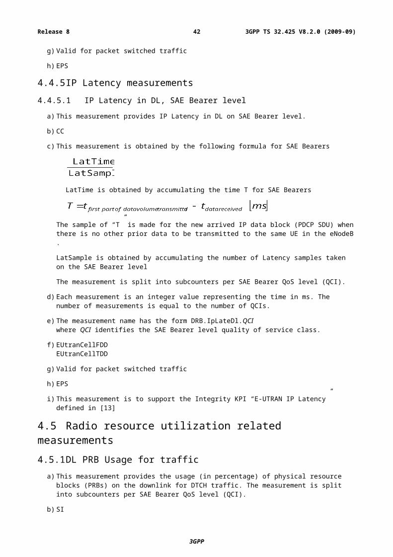
whether there is enough capacity in the network; for example, is the backhaul sufficient. Separate counters should be configured on the downlink and uplink. Complexity may be reduced by performing the counters at layer 3, giving the ingress bit-rate to the eNB on the downlink and the egress bit-rate from the eNB on the uplink.
Cell throughput includes both User Plane data and Control Plane data. To support the User Plane data, necessary Control Plane data also need to be transmitted. This Control Plane data although required, will not be perceived (felt) by the User. The total cell throughput helps to evaluate the usage of bandwidth and radio resource.
Operators ideally want to see the Control Plane data as small as possible when compared to the User Plane data without compromising on the service.
Hence it is important to monitor the total cell throughput as well as how much is occupied by Control Plane Data.
Number of actives UEs
It is also of interest to determine how many users are enjoying the throughput numbers determined for each QCI. Therefore, we may count the number of users that are active for each QCI – here active users have data queued pending transmission. A simple division of the throughput (data rate) of a QCI by the number of active users on the QCI indicates the throughput per user on the QCI. For example, taking QCI 1 this metric could indicate the typical codec rate being employed in the cell. Alternatively, for QCI 9 supporting low priority TCP-based traffic it can indicate the typical bandwidth pipe size for a user when he has data to send / receive.
DL packet delay
Latency is of prime concern for some services, particularly conversational services like speech and instant messaging. A counter is added to measure the mean delay for IP packets incurred within the eNodeB. Separate counters are provided per QCI which are particularly useful when the QCI is used by very few services and the packet sizes vary little. It is only practical to measure packet delays on the downlink.
DL packet drop rate
When a cell is heavily loaded congestion can take place. When congestion is not severe the impact is typically the incurrence of additional delay for non-GBR radio bearers. However, when congestion is severe the eNodeB may be forced to discard packets. It is important for the operator to have visibility of packet discard so that corrective action can be instigated (for example, by adjusting admission control settings in the network). It is only practical to measure packet discards on the downlink. Packet discards on handover should not be included in the count.
PRB Usage
The resource utilisation, measured in terms of physical resource blocks (PRBs), is a useful measure of whether a cell is lightly loaded or not. Loading is a key input to network capacity planning and load balancing. Furthermore, when resource utilisation per QCI is reported the distribution of resources between different services can be estimated.
Downlink Air interface packet loss rate
The downlink air interface packet loss can be directly compared with the PELR value of a QCI to see if the packet loss (over the air interface) aspect of quality of service is being met within the cell (see [12] for more details on PELR). On the downlink this measurement can be added to the congestion losses (see DL packet drop rate) to determine the total packet loss rate at the eNodeB. Consequently, the downlink useful bit-rate can be estimated by scaling the measurement of the downlink PDCP ingress bit-rate by (1 – DL packet drop rate) (1 – air interface packet loss rate).
Uplink packet loss rate
The uplink air interface packet loss rate (per QCI) can be compared directly with the PELR defined for that QCI. An estimate of the uplink air interface packet loss may be provided by the “Uplink PDCP SDU loss rate”. This uplink measurement is based on PDCP sequence numbers and cannot precisely measure the air interface losses. Any packets discarded by the UE within the protocol stack (i.e. at layer 2) are also counted since they will have been given a PDCP sequence number. Discards at layer 3 are not counted.
RACH Usage
The RACH plays a vital role in the following procedures:
3GPP
3GPP TS 32.425 V8.2.0 (2009-09)42Release 8
- Initial access from RRC_IDLE;
- Initial access after radio link failure;
- Handover requiring random access procedure;
- DL data arrival during RRC_CONNECTED requiring random access procedure;
- UL data arrival during RRC_CONNECTED requiring random access procedure;
Furthermore, the random access procedure takes two distinct forms:
- Contention based using a randomly selected preamble (applicable to all five events);
- Non-contention based using a dedicated preamble (applicable to only handover and DL data arrival).
In the use-case of RACH configuration optimization, received Random Access Preambles are signaled across an OAM interface.
Monitoring of the preamble usage in a cell allows the operator to determine if the resources allocated to the RACH by the eNodeB are appropriate for the number of random access attempts. If the resources are underutilised then the operator may reconfigure the eNodeB (via CM) to allocate less resource to RACH thereby freeing up resource for other uplink transmissions. Alternatively, if the resources are heavily utilised then this is indicative of RACH congestion leading to increased latency for the procedures listed above.
The eNodeB can partition the RACH resource between dedicated preambles, randomly selected preambles in group A and randomly selected preambles in group B. This partitioning can be evaluated when usage measurements are made on each set separately.
A.6 Monitor of the number of connected usersThe number of the connected users in each cell is valuable information for operators to know how many uses are connecting to E-UTRAN per cell basis. This kind of information can help operator to tune the admission control parameters for the cell and to do load balancing between cells to ensure that the target percentage or number the of users admitted achieve the target QoS.
A.7 Monitoring of interference situationIn the LTE radio technology interference has to be coordinated on the basis uplink and downlink i.e. in a coordinated usage of the UL resources (Physical Resource Blocks, PRBs) and DL Transmitted Power, which lead to improve SIR and corresponding throughput. These are achieved by means of mechanisms employing channel quality indicators in support of scheduling/radio resource allocation functions.
These RRM functions in the eNB require the setting of frequency / power restrictions and preferences for the resource usage in the different cells. Setting and updating these parameters is the task of a network optimisation (done by operator or automatically by SON).
Use cases for the related interference measurements are e.g. optimisation of ICIC related RRM functionality, the detection of long distance interferer and the interference due to spurious emissions of neighbour cells. The later case is assumed only in high load scenarios or unsufficent ICIC functionality due to the the fact that ICIC functionality would minimise interference autonomously if sufficient bandwidth is available.
The necessary measurements to identify and anylse the interference situation as input for optimisation tasks has to be defined.
A.8 Monitor of ARQ and HARQ performanceReliable Packet Delivery is one of the important Performance factor for a better User experience. HARQ retransmissions at the MAC layer ensure reliable packet delivery
In addition, RLC can be configured to operate in acknowledged mode for those applications that need very low packet drops and can tolerate a slightly higher delay from RLC retransmissions.
3GPP
3GPP TS 32.425 V8.2.0 (2009-09)43Release 8
If a MAC PDU is not delivered, HARQ takes care of retransmitting (upto a maximum configurable number). If all the retransmissions fail at MAC layer, and if RLC is configured to operate in acknowledged mode, RLC’s ARQ mechanism will take care of any residual packet errors.
It is important toa) maintain the block error rate or packet error rate within tolerable limits
b) ensure that HARQ retransmissions take care of most packet errors, instead of relying on RLC layer retransmissions (which would increase the delay).
So, it is important to monitor the performance of these schemes.ARQ Performance if viewed at QCI level can help in monitoring the distribution for each of the services.
HARQ Performance if viewed at MCS (Modulation Coded Scheme) can help in monitoring the MCS Performance also.
A.9 Monitor of RF performanceRF Performance reflects the cell loading levels and abnormal conditions.
In the Downlink, Power Resources are managed by the EUTRAN Cell(RAN).More Power Resources may help in increasing the Capacity of the System. Hence, there the power resources could be effectively used to optimize the Capacity of the System.
Hence there is a need to keep monitoring the Power Resource Utilization in % and also in absolute terms.
A.10 Monitor of paging performanceIn EUTRAN, Paging is under the control of the MME. When the MME wants to page a UE it has to page it in all cells that belong to the TA(s) to which the UE is registered.
The paging load per cell is an important measure for the operator as it allows the operator to properly dimension the resources for paging in the E-UTRAN Cell .
At an E-UTRAN Cell it makes sense to measure the number of discarded paging messages if this is due to some problem in the eNodeB, such as paging occasion overflow. In that scenario the periodicity of paging occasions can be reconfigured in order to ensure that all paging messages are transmitted by the eNodeB in the first available paging occasion, thereby avoiding paging delays and extended call setup delay.
Operators need to know when such an event occurs, in order to identify if the problem is at the E-UTRAN cell level or not.
3GPP
3GPP TS 32.425 V8.2.0 (2009-09)44Release 8
Annex B (informative): Change history
Change historyDate TSG # TSG Doc. CR Re
vSubject/Comment Cat Old New
Mar 2009 SP-43 SP-090143 -- -- Presentation to SA for information and approval -- 1.0.0
8.0.0
Jun 2009 SP-44 SP-090408 002 -- Add missing E-UTRAN measurement for paging discards at the eNodeB - Align with 36.304 and 32.426
F 8.0.0
8.1.0
Sep 2009 SP-45 SP-090534 003 -- Correction on the IP latency and additional SAE Bearers setup measurements
F 8.1.0
8.2.0
Sep 2009 SP-45 SP-090534 005 -- Alignment of PRB usage related measurements with 36.314 F 8.1.0
8.2.0
3GPP
3GPP TS 32.425 V8.2.0 (2009-09)45Release 8