Embed Size (px)
Citation preview

© 2014 City and Guilds of London Institute. All rights reserved.
Page 1 of 92
SCHEME OF WORK FOR LEVEL 4 DIPLOMA IN MECHANICAL ENGINEERING
UNIT 428 ELECTRICAL PRINCIPLES FOR MECHANICAL ENGINEERING
Lesson 1: Magnetic theory revision Suggested Teaching Time: 2 hours
Learning Outcome 1: Understand the electromagnetic theory of transformers
Topic Suggested Teaching Suggested Resources
Revision of
magnetism
Relationship
between common
electromagnetic
units of
measurement
(AC 1.1)
Tutor to note that the learner will need the following underpinning knowledge:
Lenz’s law
Faraday’s laws
Fleming’s rules
Mutual induction
Self-induction
Frequency
Sine waves
Amplitude
Root mean square values
Peak-to-peak values
Basic semiconductor theory of a p-n junction.
They may need to recap certain areas of knowledge throughout the course
Books:
Patrick, Dale R., and Fardo, Dale R.,
Electricity and Electronics
Fundamentals, The Fairmont Press,
Inc., 2008, ISBN 0881736023,
9780881736021
Jiles, David C., Introduction to
Magnetism and Magnetic Materials,
Second Edition, CRC Press, 1998,
ISBN-10: 0412798603, ISBN-13:
9780412798603
Practical Equipment:
Bar magnets, horseshoe magnets,
electromagnets, solenoids paper iron
filings(or similar magnetic powder)
Software:
http://phet.colorado.edu/en/simulation/fa
raday
http://www.infolytica.com/en/products/m
agnet/
Whole-class discussion and practical experiment session, tutor to lead a
discussion on the basic principles of magnetism and to demonstrate using lab
equipment. Tutor to cover:
Current convention, magnetic fields around a conductor (corkscrew
rule)
How this can be used in an electromagnet
Use of electromagnets in a solenoid.

© 2014 City and Guilds of London Institute. All rights reserved.
Page 2 of 92
SCHEME OF WORK FOR LEVEL 4 DIPLOMA IN MECHANICAL ENGINEERING
UNIT 428 ELECTRICAL PRINCIPLES FOR MECHANICAL ENGINEERING
Demonstrating practically where possible
Whole-class teaching: tutor to convey the fact that magnetic field is correctly
known as flux (ϕ or Ф) it is measured in Weber (Wb)
In the iron core part of a simple bar magnet the flux (Ф) flows through a cross-
section of area A; the flux density (В) is Ф/A
Websites:
http://hyperphysics.phy-
astr.gsu.edu/hbase/emcon.html
Whole-class teaching: tutor to explain that the flux is
assumed to have a direction North to South on the
outside but South to North on the inside. The poles
of a magnet are Red for North and Blue for South.
The flux flowing on the outside has an
indeterminate cross section and length but flux
flowing in a magnetic core has a definite cross
sectional area and length and this is important in
the next section.
Tutor to demonstrate (practically if possible) how, in the horseshoe magnet,
the flux runs through the iron and then jumps across the air gap and how the
flux is concentrated in the gap. Demonstrate that the gap has a definite cross
sectional area and length. For the horseshoe magnet shown the cross
sectional area of the gap is 200 mm2and the flux flowing through it is 0.16 Wb.
B = ФA⁄ = 0.16
200 × 10−6⁄ = 800 Tesla

© 2014 City and Guilds of London Institute. All rights reserved.
Page 3 of 92
SCHEME OF WORK FOR LEVEL 4 DIPLOMA IN MECHANICAL ENGINEERING
UNIT 428 ELECTRICAL PRINCIPLES FOR MECHANICAL ENGINEERING
Lesson 2: Electromagnetism Suggested Teaching Time: 4 hours
Learning Outcome 1: Understand the electromagnetic theory of transformers
Topic Suggested Teaching Suggested Resources
Electromagnetism
Relationship
between common
electromagnetic
units of
measurement
(AC 1.1)
Tutor to explain that in the following work, it is useful to think of a magnetic
flux created by a coil wound on a ring (toroid) of magnetic material as shown.
Demonstrate this practically if possible.
This ring forms a complete circuit of uniform cross sectional area 𝐴 and
length 𝑙 .
The tutor may find that it is also beneficial to get the students to compare the
circuit with an electrical circuit. In a simple electric circuit the current flowing 𝐼
depends on the voltage 𝑉 and the resistance 𝑅.
In the magnetic circuit, a flux ϕ flows. The strength of the flux depends on the
Books:
Jiles, David C., Introduction to
Magnetism and Magnetic Materials,
Second Edition, CRC Press, 1998,
ISBN-10: 0412798603, ISBN-13:
9780412798603
Practical Equipment:
Lab equipment to demonstrate
electromagnets and the effect on
number of coils etc
Software:
http://phet.colorado.edu/en/simulation/fa
raday
http://www.infolytica.com/en/products/m
agnet/
Websites:
http://hyperphysics.phyastr.gsu.edu/hba
se/emcon.html

© 2014 City and Guilds of London Institute. All rights reserved.
Page 4 of 92
SCHEME OF WORK FOR LEVEL 4 DIPLOMA IN MECHANICAL ENGINEERING
UNIT 428 ELECTRICAL PRINCIPLES FOR MECHANICAL ENGINEERING
coil and this property is called the magneto motive force (MMF) (see below).
Tutor to explain that it therefore follows that we need a property equivalent to
resistance to describe how easy it is for the flux to flow. This property is called
‘reluctance’.
In electric circuits resistance depends on a property of the material called the
conductivity (or resistivity). Tutor to explain that it therefore follows that in the
same way, the reluctance of a material depends on a property called the
‘permeability’.
The amount of magnetisation left behind in a magnetic material (such as iron)
after an external magnetic field is removed is known as the ‘remanence’.
Split class into smaller groups and get students to carry out experiments using
different materials, coil sizes etc. Tutor to circulate and assist where required,
encouraging students to discuss their findings with each other and how they
relate to the subjects learned so far.

© 2014 City and Guilds of London Institute. All rights reserved.
Page 5 of 92
SCHEME OF WORK FOR LEVEL 4 DIPLOMA IN MECHANICAL ENGINEERING
UNIT 428 ELECTRICAL PRINCIPLES FOR MECHANICAL ENGINEERING
Topic Suggested Teaching Suggested Resources
Relationship
between common
electromagnetic
units of
measurement
(AC 1.1)
Whole-class teaching to cover the following points:
Magneto Motive Force (MMF)
Tutor to explain: how MMF is created by the current flowing in the coil; how it
is directly proportional to the current ‘I’ and the number of turns of the coil ‘T’.
MMF = I T. The units are ampere turns (AT).
Tutor to explain how permanent magnets have a theoretical MMF to explain
the permanent flux.
Magnetising Force (H)
Tutor to explain using the toroid used in the previous section, discussing how
it formed a complete ring of uniform cross section. Where the length l is the
mean circumference of the ring. The H is defined as the MMF divided by l
H = I Tl⁄ The units are AT per metre.
Tutor to demonstrate formula by use of an example such as
A coil is wound on a toroid core 50 mm mean diameter. There are 500 turns.
Calculate the MMF and the H when a current of 2A is applied.
Solution
MMF = I T = 2 × 500 = 1000 AT
l = circumference = πD = π × 0.05 = 0.157m
H = MMFl⁄ = 1000
0.157⁄ = 6366.2 AT/m
Books:
Jiles, David C., Introduction to
Magnetism and Magnetic Materials,
Second Edition, CRC Press, 1998,
ISBN-10: 0412798603, ISBN-13:
9780412798603
Practical Equipment:
Lab equipment to demonstrate
electromagnets and the effect on
number of coils etc.
Software:
http://phet.colorado.edu/en/simulation/fa
raday
http://www.infolytica.com/en/products/m
agnet/
Websites:
http://hyperphysics.phy-
astr.gsu.edu/hbase/emcon.html

© 2014 City and Guilds of London Institute. All rights reserved.
Page 6 of 92
SCHEME OF WORK FOR LEVEL 4 DIPLOMA IN MECHANICAL ENGINEERING
UNIT 428 ELECTRICAL PRINCIPLES FOR MECHANICAL ENGINEERING
Lesson 3: Electromagnetism (continued) Suggested Teaching Time: 4 hours
Learning Outcome 1: Understand the electromagnetic theory of transformers
Topic Suggested Teaching Suggested Resources
Relationship
between common
electromagnetic
units of
measurement
(AC 1.1)
Relationship between B and H
Tutor to explain/demonstrate using the example of toroid used earlier.
The toroid has a uniform cross sectional area A so the flux density is simply B
= ϕ/A.
The flux and hence flux density depends on the MMF and hence the
magnetising force.
For any coil it is found that B/H = constant. It has been found that for a simple
coil with no core at all (a complete vacuum), the constant is 12.566 x 10⁻⁷ and
this is called the ‘absolute permeability of free space’ and has a symbol μo.
Tutor to demonstrate that if a magnetic material such as iron is placed inside
the coil, the constant increases.
The ratio by which the constant increases is called the ‘relative permeability’
and has a symbol μr. It therefore follows that: B/H = μoμr
Tutor to explain/demonstrate how it is difficult to apply this to a simple coil as
the length of the magnetic circuit is not obvious unless the coil is wound on a
magnetic material to produce a circuit.
Tutor to explain/demonstrate using the example of the simple toroid circuit
again. Tutor to discuss that for the electric analogy we have Ohm’s law
V
I= R
Books:
Jiles, David C., Introduction to
Magnetism and Magnetic Materials,
Second Edition, CRC Press, 1998,
ISBN-10: 0412798603, ISBN-13:
9780412798603
Practical Equipment:
Lab equipment to demonstrate
electromagnets and the effect of using
different coils and to show the different
properties discussed in lesson
Software:
http://phet.colorado.edu/en/simulation/fa
raday
http://www.infolytica.com/en/products/m
agnet/
Websites:
http://hyperphysics.phy-
astr.gsu.edu/hbase/emcon.html

© 2014 City and Guilds of London Institute. All rights reserved.
Page 7 of 92
SCHEME OF WORK FOR LEVEL 4 DIPLOMA IN MECHANICAL ENGINEERING
UNIT 428 ELECTRICAL PRINCIPLES FOR MECHANICAL ENGINEERING
Therefore by analogy, in the magnetic circuit
MMFϕ⁄ = reluctance.
Tutor to show that by substituting B =ϕ
A⁄ and H = MMFl⁄ into this equation
we get
ϕl (A MMF)⁄ = μoμr
and that by rearranging it we get
MMFϕ⁄ = l
(Aμoμr)⁄ = Reluctance
Reluctance = l (Aμoμr)⁄
The units are AT/Wb
Tutor to split students into smaller groups and hand out a series of questions
based on the subject learned so far including questions based on the formula.
Tutor to circulate and assist where required.

© 2014 City and Guilds of London Institute. All rights reserved.
Page 8 of 92
SCHEME OF WORK FOR LEVEL 4 DIPLOMA IN MECHANICAL ENGINEERING
UNIT 428 ELECTRICAL PRINCIPLES FOR MECHANICAL ENGINEERING
Topic Suggested Teaching Suggested Resources
B-H Graphs
Relationship
between common
electromagnetic
units of
measurement
(AC 1.1)
Tutor to demonstrate
practically where
possible how B-H
graphs are created
and allow students to
conduct experiments
to create their own
graphs for various
materials.
Tutor then to get
students to discuss
their findings. Tutor-
led discussion
towards a conclusion
that for magnetic
materials, the relative
permeability μr is not
constant as implied
previously and B is not directly proportional to H. This then go on to explain
that this is not a major problem as manufacturers produce the information in
the form of a B-H graph and we can find the values of one if the other is
known. Tutor to add that for non-magnetic materials μr is always about 1.0 In
a typical graph (shown), the value of B increase directly with H when the
values of I are small but when the values of H become large, B becomes
constant. When B is constant, the magnetic core is said to be ‘Saturated’.
Books:
Jiles, David C., Introduction to
Magnetism and Magnetic Materials,
Second Edition, CRC Press, 1998,
ISBN-10: 0412798603, ISBN-13:
9780412798603
Practical Equipment:
Lab equipment to demonstrate
electromagnets and the effect of using
different coils and to show the different
properties discussed in lesson and the
effect of reversing the current
Software:
http://phet.colorado.edu/en/simulation/fa
raday
http://www.infolytica.com/en/products/m
agnet/
Websites:
http://hyperphysics.phy-
astr.gsu.edu/hbase/emcon.html

© 2014 City and Guilds of London Institute. All rights reserved.
Page 9 of 92
SCHEME OF WORK FOR LEVEL 4 DIPLOMA IN MECHANICAL ENGINEERING
UNIT 428 ELECTRICAL PRINCIPLES FOR MECHANICAL ENGINEERING
Lesson 4: Hysterisis Suggested Teaching Time: 2 hour
Learning Outcome 1: Understand the electromagnetic theory of transformers
Topic Suggested Teaching Suggested Resources
Changes in
magnetic properties
of a soft iron core
undergoing cyclic
magnetisation
(AC 1.2)
Whole-class teaching, tutor
to demonstrate, practically
where possible, the
phenomenon associated
with magnetic materials that
are capable of being
permanently magnetised
which is known as
‘hysteresis’.
Tutor to demonstrate with a
simple electromagnet how
magnetic flux is created by a
coil carrying a direct current and that the material becomes permanently
magnetised. They should then reverse the current and show the effect
Whole-class discussion to cover what happens when the current is alternating
so that it reverses at regular intervals (50 times a second for mains
frequency).
Tutor to talk students through cycle while demonstrating practically and
showing the B-H curve.
A current is applied and a flux is produced. If the current is gradually

© 2014 City and Guilds of London Institute. All rights reserved.
Page 10 of 92
SCHEME OF WORK FOR LEVEL 4 DIPLOMA IN MECHANICAL ENGINEERING
UNIT 428 ELECTRICAL PRINCIPLES FOR MECHANICAL ENGINEERING
increased and the values of B are plotted against H we get a B-H graph from 1
to 2.
At point 2, a further increase in current does not produce an increase in B and
the core is said to be saturated.
If the current is switched off at this point the iron core will remain magnetised
and form a permanent magnet.
If the current is gradually reduced from its maximum value and we continue to
plot B against H we will get the graph 2 to 3.
At point 3 the current is zero but we now have a flux because the core is
magnetised in one direction and forms a permanent magnet. In order to
reduce the magnetic flux to zero, we must apply a negative current and this
takes the graph to point 4.
Continuing to increase the current in the negative direction increases the flux
in a negative direction (N and S poles are reversed) and the graph 4 to 5 is
obtained (this resistance to demagnetisation is called the ‘Coercivity’ of the
material).
At this point the iron is magnetised in the opposite direction to before.
If the current is reduced back to zero the graph 5 to 6 is obtained and at point
6 the current is again zero but there is a permanent flux opposite in direction
to before. If the current is now increased in the positive direction again the flux
will be reduced to zero at point 7 and then increases positively back to point 2.
If we continue to alternate the current plus and minus (i.e. apply A.C.) the B-H
graph will follow the loop 2, 3, 4, 5, 6, 7, 2 over and over again.
Tutor to discuss the fact that this loop illustrates the ‘hysteresis effect’.

© 2014 City and Guilds of London Institute. All rights reserved.
Page 11 of 92
SCHEME OF WORK FOR LEVEL 4 DIPLOMA IN MECHANICAL ENGINEERING
UNIT 428 ELECTRICAL PRINCIPLES FOR MECHANICAL ENGINEERING
Lesson 5: Applied magnetism Suggested Teaching Time: 1 hour
Learning Outcome 2: Understand the principles of DC machines
Topic Suggested Teaching Suggested Resources
Force on a
conductor, AC 2.2
Tutor to recap creating and destroying a magnet and basic application of an
electromagnet in a solenoid.
Whole-class discussion on where we can find magnets and for what they are
used. Lead if necessary towards electromagnets for moving things, solenoids,
motors and transformers.
Tutor-led experiment:
The students set up a horseshoe magnet in a clamp, hold a wire between the
ends of the magnet and then cause a current to flow through the wire.
Whole-class discussion on the results to cover: a major discovery leading to
the invention of the electric motor was that a conductor placed in a magnetic
field experiences a force when current flows in it.
Tutor to draw a diagram to show a conductor placed in a gap between the
poles of a magnet.
then to show that when current passes through the conductor, we have two
magnetic fields, the circular lines around the conductor and the parallel lines
between the poles. The lines of magnetism between the north and south poles
would rather pass over the top of the conductor because both lines are in the
same direction on top. The lines behave like elastic bands and force the
conductor down. If the direction of either the current or the magnetic field is
Books:
Jiles, David C., Introduction to
Magnetism and Magnetic Materials,
Second Edition, CRC Press, 1998,
ISBN-10: 0412798603, ISBN-13:
9780412798603
Practical Equipment:
Lab equipment to demonstrate electric
motors. E.g. magnets, coils, wire and
power source
Software:
http://phet.colorado.edu/en/simulation/fa
raday
http://www.infolytica.com/en/products/m
agnet/
Websites:
http://hyperphysics.phy-
astr.gsu.edu/hbase/emcon.html

© 2014 City and Guilds of London Institute. All rights reserved.
Page 12 of 92
SCHEME OF WORK FOR LEVEL 4 DIPLOMA IN MECHANICAL ENGINEERING
UNIT 428 ELECTRICAL PRINCIPLES FOR MECHANICAL ENGINEERING
reversed, the force will act up. Tutor to explain Fleming’s left-hand rule
Tutor to discuss how the force on the conductor is directly proportional to the
current ‘𝐼’ , the magnetic flux density ‘𝐵’ and the length ‘𝑙’ of the conductor
within the flux.
Emphasise that this is an important equation:
The force on a conductor 𝑭 = 𝑩 𝒍 𝑰
Tutor then to get
the students to set
up a simple electric
loop within a
magnetic field
Tutor to
demonstrate how
this produces a
downwards force
on one side and an
upwards force on
the other at a
radius R. This
produces a torque on the coil of T = F R. This will make the loop rotate.
Tutor to discuss a practical application of this principle with the moving coil
meter. The loop or coil rotates only 90𝑜 and rotation is governed by a spring.
The loop is connected to a pointer which moves on a scale. The movement is
directly proportional to current in the coil. 𝑭 = 𝑩𝒍𝑰
Books:
Hughes, Austin, Electric Motors and
Drives: Fundamentals, Types and
Applications, 4th edition, Newnes, 2013,
ISBN-10: 0080983324, ISBN-13: 978-
0080983325
Practical Equipment:
Lab equipment to test various electric
motors, including moving coil meter
Websites:
http://www.animations.physics.unsw.edu
.au/downloads.htm#electric

© 2014 City and Guilds of London Institute. All rights reserved.
Page 13 of 92
SCHEME OF WORK FOR LEVEL 4 DIPLOMA IN MECHANICAL ENGINEERING
UNIT 428 ELECTRICAL PRINCIPLES FOR MECHANICAL ENGINEERING
Lesson 6: DC motors Suggested Teaching Time: 2 hours
Learning Outcome 2: Understand the principles of DC machines
Topic Suggested Teaching Suggested Resources
Tutor to develop ideas learned in last lesson aiming towards a practical DC
motor.
Return class’s attention to the basic motor and discuss the flaw with this
design in so far as when it turns 90o the radius is zero and the torque is zero
so it will stop. Get students to discuss how we can overcome this. If we
reverse the current as it passes the 90o position the torque will continue to
make it rotate.
Switching the
direction of the
current every half
rotation will
produce
continuous
rotation. This can
be done with a
split ring
Get students to elaborate on this and to come up with improvements such as
by using several loops and switching the current to the one in the horizontal
position all the time. The split ring becomes a commutator with many
segments. Each pair of segments is connected to a loop and each pair in turn
becomes connected to the brushes as it rotates.
Books:
Hughes, Austin, Electric Motors and
Drives: Fundamentals, Types and
Applications, 4th edition, Newnes, 2013,
ISBN-10: 0080983324, ISBN-13: 978-
0080983325
Practical Equipment:
Lab equipment to test various electric
motors, including DC Series, shunt and
Compound
Websites:
http://www.electrical4u.com/lap-winding-
simplex-and-duplex-lap-winding/

© 2014 City and Guilds of London Institute. All rights reserved.
Page 14 of 92
SCHEME OF WORK FOR LEVEL 4 DIPLOMA IN MECHANICAL ENGINEERING
UNIT 428 ELECTRICAL PRINCIPLES FOR MECHANICAL ENGINEERING
Lap and wave
windings
Tutor to develop idea of multiple windings to discover how armatures are
wound. Show practical examples where possible
Tutor to explain that armature windings are mainly of two types:
1. Lap winding
2. Wave winding
Lap winding is the winding in which successive coils overlap each other. It is
named lap winding because it doubles or laps back with its succeeding coils.in
this winding the finishing end of one coil is connected to one commutator
segment and the starting end of the next coil situated under the same pole
and connected with same commutator segment A winding in which the
number of parallel path between the brushes is equal to the number of poles
is called simplex lap winding. A winding in which the number of parallel path
between the brushes is twice the number of poles is called duplex lap winding.
Advantages of lap winding
This winding is necessarily required for large electric current application
because it has more parallel paths.
It is suitable for low voltage and high electric current generators.
Disadvantages of lap winding
It gives less emf compared to wave winding. This winding requires a
higher number of conductors to give the same emf, resulting in higher
winding cost.
It has less efficient utilisation of space in the armature slots.

© 2014 City and Guilds of London Institute. All rights reserved.
Page 15 of 92
SCHEME OF WORK FOR LEVEL 4 DIPLOMA IN MECHANICAL ENGINEERING
UNIT 428 ELECTRICAL PRINCIPLES FOR MECHANICAL ENGINEERING
With wave windings the number of parallel paths between conductors A is
always equal to 2 irrespective of the number of poles. In this winding the end
of one coil is connected to the starting of another coil of the same polarity as
that of the first coil. In this type of winding the coil side (A-B) progress forward
around the armature to another coil side and goes on successively passing
through N and S pole till it returns to a conductor (A1-B1) lying under the
starting pole. This winding forms a wave with its coil. That’s why it is named as
wave winding. It is also called series winding because its coils are connected
in series. If after one round of the armature the coil falls in a slot right of its
starting slot the winging is called progressive wave winding. If after one round
of the armature the coil falls in a slot left of its starting slot the wiring is called
'retrogressive wave winding’.

© 2014 City and Guilds of London Institute. All rights reserved.
Page 16 of 92
SCHEME OF WORK FOR LEVEL 4 DIPLOMA IN MECHANICAL ENGINEERING
UNIT 428 ELECTRICAL PRINCIPLES FOR MECHANICAL ENGINEERING
Topic Suggested Teaching Suggested Resources
Wave Windings
c
o
n
t
i
n
u
e
d
Tutor to discuss characteristics and advantage of simplex wave winding.
In this winding only two brushes are required but more parallel brushes can be
added to make it equal to the no. of poles. If one or more brushes set poor
contacts with the commutator, satisfactory operation is still possible.
This winding gives sparkles commutation. The reason behind that it has two
parallel paths irrespective of no of poles of the machine. The conductors in
each of the two parallel path distributed around the armature in the entire
circumference.
Number of conductors in each path = Z/2 , Z is the total number of conductors.
Generated emf = average emf induced in each path X Z/2
For a given number of poles and armature conductors it gives more emf than
that of lap winding. Hence wave winding is used in high voltage and low
electric current machines This winding is suitable for small generators circuit
with voltage rating 500-600V.
Current flowing through each conductor =Current per path (Ia)
2 Iais the armature
current. Current per path for this kind of winding must not be exceeded 250A.
Resultant emf around the entire circuit is zero.
Disadvantage of simplex wave winding
Wave winding cannot be used in the machines having higher electric current
rating because it has only two parallel paths.
Books:
Hughes, Austin, Electric Motors and
Drives: Fundamentals, Types and
Applications, 4th edition, Newnes, 2013,
ISBN-10: 0080983324, ISBN-13: 978-
0080983325
Practical Equipment:
Lab equipment to test various electric
motors, including DC Series, shunt and
Compound
Websites:
http://www.electrical4u.com/lap-winding-
simplex-and-duplex-lap-winding/

© 2014 City and Guilds of London Institute. All rights reserved.
Page 17 of 92
SCHEME OF WORK FOR LEVEL 4 DIPLOMA IN MECHANICAL ENGINEERING
UNIT 428 ELECTRICAL PRINCIPLES FOR MECHANICAL ENGINEERING
Lesson 7: DC motors (continued) Suggested Teaching Time: 1 hour
Learning Outcome 2: Understand the principles of DC machines
Topic Suggested Teaching Suggested Resources
Field windings
and armature
arrangements
Whole-class teaching: tutor to show that there are various ways of arranging
the windings but the two most common ways are in series and as a shunt.
Books:
Hughes, Austin, Electric Motors and
Drives: Fundamentals, Types and
Applications, 4th edition, Newnes, 2013,
ISBN-10: 0080983324, ISBN-13: 978-
0080983325
Practical Equipment:
Lab equipment to test various electric
motors, including DC Series, shunt and
Compound
Websites:
http://www.electrical4u.com/lap-winding-
simplex-and-duplex-lap-winding/
Series motor
Tutor to demonstrate, practically where possible, how, in a series motor, the
field winding is in series
with the armature. And
that the same current
flows through the
armature and the field
winding.
The mechanical power
of any rotor is 𝑃 = 2𝜋𝑁𝑇
The electric power of
any rotor is ideally 𝑃 =
𝐸𝑎𝐼𝑎
Equating and rearranging we see that 𝑇 = 𝐸𝑎𝐼𝑎
2𝜋𝑁⁄
If the electric power is constant, 𝐸𝑎𝐼𝑎 are constant so T = Constant/N
This means that for a constant electrical power the speed would increase as
the load is removed and decrease as the load increases as shown by the
graph.
© 2014 City and Guilds of London Institute. All rights reserved.
Page 18 of 92
SCHEME OF WORK FOR LEVEL 4 DIPLOMA IN MECHANICAL ENGINEERING
UNIT 428 ELECTRICAL PRINCIPLES FOR MECHANICAL ENGINEERING
Advantage
At low speed there is a high torque (starting torque) which is ideal for servo
applications.
Disadvantage
At low torque (no load conditions) the motor is liable to over speed and
become damaged.
Shunt motor In this case the field
winding is connected in
parallel with the armature
as shown.
The field current is
constant so flux cannot be
changed except by
changing the supply
voltage.
𝐸𝑎 = 𝑉 = 𝐼𝑎𝑅𝑎
It can be shown that 𝑇 = 𝐶1 − 𝐶2𝑁
C1 and C2 are constants.
This shows that at zero speed the starting torque is C1 and as speed
increases, the torque drops off. The ideal torque-speed characteristic is as
shown. In reality the line is curved down due to other effects not considered.

© 2014 City and Guilds of London Institute. All rights reserved.
Page 19 of 92
SCHEME OF WORK FOR LEVEL 4 DIPLOMA IN MECHANICAL ENGINEERING
UNIT 428 ELECTRICAL PRINCIPLES FOR MECHANICAL ENGINEERING
Lesson 8: DC motors (continued) Suggested Teaching Time: 6 hours
Learning Outcome 2: Understand the principles of DC machines
Topic Suggested Teaching Suggested Resources
Represent the
characteristic
curves of the
different types of
DC motors in a
diagram
(AC 2.4)
Evaluate the
relative
characteristics of
different types of
DC motors
(AC 2.5)
Whole-class teaching with practical demonstrations/student participation in
testing where possible
Tutor to get student to carry out practical activities to record the data required
for each of the following characteristics and to discuss the results
DC series motor
Torque vs. armature current (Ta-Ia)
This characteristic is also known as electrical characteristic. We know that
torque is directly proportional to armature current and flux, Ta ∝ Φ × Ia. In DC
series motors, field winding is connected in series with armature. Thus, before
magnetic saturation of the field, flux Φ is directly proportional to Ia. Therefore,
Books:
Hughes, Austin, Electric Motors and
Drives: Fundamentals, Types and
Applications, 4th edition, Newnes, 2013,
ISBN-10: 0080983324, ISBN-13: 978-
0080983325
Practical Equipment:
Lab equipment to test various electric
motors, including DC Series, shunt and
Compound
Websites:
http://www.electrical4u.com/lap-winding-
simplex-and-duplex-lap-winding/

© 2014 City and Guilds of London Institute. All rights reserved.
Page 20 of 92
SCHEME OF WORK FOR LEVEL 4 DIPLOMA IN MECHANICAL ENGINEERING
UNIT 428 ELECTRICAL PRINCIPLES FOR MECHANICAL ENGINEERING
before magnetic saturation Ta ∝ Ia2. At light loads, Ia as well as Φ is small
and hence the torque increases as the square of the armature current.
Therefore, the Ta-Ia curve is parabola for smaller values of Ia.
After magnetic saturation of the field winding, flux Φ is independent of
armature current Ia. Therefore, the torque varies proportional to Ia only, T ∝
Ia. Therefore, after magnetic saturation, Ta-Ia curve becomes straight line.
The shaft torque (Tsh) is less than armature torque (Ta) due to stray losses. In
DC series motors, (prior to magnetic saturation) torque increases as the
square of armature current, these motors are used where high starting torque
is required
Speed vs. armature current (N-Ia)
We know the relation, N ∝ Eb/Φ
For a small load current (and hence for small armature current) the change in
back emf Eb is small and it may be neglected. Thus, for small currents, speed
is inversely proportional to Φ. As we know, flux is directly proportional to Ia,
speed is also inversely proportional to Ia.
When armature current is very small the speed becomes dangerously high.
That is why a series motor should never be started without some mechanical
load. But, at heavy loads, armature current Ia is large. And hence speed is low
which results in decreased back emf Eb. Due to decreased Eb, more armature
current is allowed
Speed vs. torque (N-Ta)
This characteristic is also called as mechanical characteristic. From the above
two characteristics of a DC series motor, it can be found that when speed is
high, torque is low and vice versa.

© 2014 City and Guilds of London Institute. All rights reserved.
Page 21 of 92
SCHEME OF WORK FOR LEVEL 4 DIPLOMA IN MECHANICAL ENGINEERING
UNIT 428 ELECTRICAL PRINCIPLES FOR MECHANICAL ENGINEERING
Topic Suggested Teaching Suggested Resources
Represent the
characteristic
curves of the
different types of
DC motors in a
diagram
(AC 2.4)
Evaluate the
relative
characteristics of
different types of
DC motors
(AC 2.5) DC shunt motors
Torque vs. armature current (Ta-Ia)
In case of DC shunt motors we can assume the field flux Φ to be constant.
Though at heavy loads, Φ decreases in a small amount due to increased
armature reaction. But as we are neglecting the change in the flux Φ, we can
say that torque is proportional to armature current. Hence the Ta-Ia
characteristic for a DC shunt motor will be a straight line through origin.
Since, heavy starting load needs heavy starting current, shunt motor should
never be started on a heavy load.
Books:
Hughes, Austin, Electric Motors and
Drives: Fundamentals, Types and
Applications, 4th edition, Newnes, 2013,
ISBN-10: 0080983324, ISBN-13: 978-
0080983325
Practical Equipment:
Lab equipment to test various electric
motors, including DC series, shunt and
compound
Websites:
http://www.electrical4u.com/lap-winding-
simplex-and-duplex-lap-winding/

© 2014 City and Guilds of London Institute. All rights reserved.
Page 22 of 92
SCHEME OF WORK FOR LEVEL 4 DIPLOMA IN MECHANICAL ENGINEERING
UNIT 428 ELECTRICAL PRINCIPLES FOR MECHANICAL ENGINEERING
Speed vs. armature current (N-Ia)
As flux Φ is assumed constant, we can say N ∝ Eb. But, back emf is also
almost constant, the speed remains constant. But practically, Φ as well as Eb
decreases with increase in load. But, the Eb decreases slightly more than Φ,
and hence the speed decreases slightly. Generally, the speed decreases by 5
to 15% of full load speed only. And hence, a shunt motor can be assumed as
a constant speed motor.
DC compound motor
DC compound motors have both series as well as shunt windings. In a
compound motor series and shunt windings are connected such that series
flux is in direction with shunt flux then the motor is said to be cumulatively
compounded. And if series flux is opposite direction as that of the shunt flux,
then the motor is said to be differentially compounded.

© 2014 City and Guilds of London Institute. All rights reserved.
Page 23 of 92
SCHEME OF WORK FOR LEVEL 4 DIPLOMA IN MECHANICAL ENGINEERING
UNIT 428 ELECTRICAL PRINCIPLES FOR MECHANICAL ENGINEERING
Cumulative compound motors
These are used where series characteristics are required but the load is likely
to be removed completely. Series winding takes care of the heavy load,
whereas the shunt winding prevents the motor from running at dangerously
high speed when the load is suddenly removed. These motors are generally
employed in systems using a flywheel, where sudden and temporary loads are
applied like in rolling mills.
Differential compound motors
Since in differential field motors, series flux opposes shunt flux, the total flux
decreases with increase in load. Due to this, the speed remains almost
constant or even it may increase slightly with increase in load. Differential
compound motors are not commonly use, but they find limited applications in
experimental and research work.
Tutor to split students into smaller groups and hand out a series of questions
based on the subject learned so far including questions based on the formula.
Tutor to circulate and assist where required

© 2014 City and Guilds of London Institute. All rights reserved.
Page 24 of 92
SCHEME OF WORK FOR LEVEL 4 DIPLOMA IN MECHANICAL ENGINEERING
UNIT 428 ELECTRICAL PRINCIPLES FOR MECHANICAL ENGINEERING
Lesson 9: Electromagnetic induction Suggested Teaching Time: 1 hour
Learning Outcome 1: Understand the electromagnetic theory of transformers
Topic Suggested Teaching Suggested Resources
Electromagnetic
Induction
(AC 1.4)
Whole-class discussion and or practical experiments to cover the Generator
Principle.
Students to discover by practical experiment that by inserting a magnet into a
coil as shown all the flux cuts across the turns of the conductor at 90o and
induces an emf Tutor to emphasise that an emf is generated only when the
magnet is moved. Changing the direction of movement changes the polarity of
the emf Tutor to explain Fleming’s right hand rule
Student to get students to conduct a series of experiments using various sized
magnets and coils and to record their findings. Tutor then to lead a discussion
on the findings; lead students towards the fact that the emf is directly
proportional to the flux density B, the velocity v and the length of the conductor
Books:
Bhandari, N. S., Together with Physics:
12 Cbse Syllabus, Rachna Sagar, 2009,
ISBN 818741412X, 9788187414124
Practical Equipment:
Lab equipment for generating electricity
and demonstrating principles
Websites:
http://www.learnabout-
electronics.org/index.php

© 2014 City and Guilds of London Institute. All rights reserved.
Page 25 of 92
SCHEME OF WORK FOR LEVEL 4 DIPLOMA IN MECHANICAL ENGINEERING
UNIT 428 ELECTRICAL PRINCIPLES FOR MECHANICAL ENGINEERING
within the flux l.
Tutor to then reason with students that It therefore follows that the emf is
given by: 𝒆 = 𝑩 𝒍 𝒗 (the generator
equation)
Whole-class discussion to
cover the similarity
between a DC motor and
the generator. However,
instead of passing current
into the loop, the loop is
made to rotate and a
voltage is generated
across the end of the
loop. Tutor to explain how
the current flowing from the terminals is governed by the resistance connected
between them (e.g. the resistance of a light bulb).

© 2014 City and Guilds of London Institute. All rights reserved.
Page 26 of 92
SCHEME OF WORK FOR LEVEL 4 DIPLOMA IN MECHANICAL ENGINEERING
UNIT 428 ELECTRICAL PRINCIPLES FOR MECHANICAL ENGINEERING
Lesson 10: Electricity generation Suggested Teaching Time: 2 hour
Learning Outcome 1: Understand the electromagnetic theory of transformers
Topic Suggested Teaching Suggested Resources
Electricity
generation
Tutor-led discussion to conclude that the voltage generated is directly
proportional to the angle of the loop to the flux ‘θ’. The output voltage is given
by 𝑽 = 𝑽𝒎𝒂𝒙 𝑺𝒊𝒏 𝜃
V max is the maximum voltage and θ is the angle of rotation.
Student to get students to conduct a series of experiments using simple
generators and oscilloscopes and to record their findings
Tutor-led discussion to conclude that the simple generator produces
alternating current which is
sinusoidal in form.
Students then to conduct
the same experiment but in
this case the coil is
connected to a split ring,
and record their results.
Books:
Patrick, Dale R., and Fardo, Dale R.,
Electricity and Electronics
Fundamentals, The Fairmont Press,
Inc., 2008, ISBN 0881736023,
9780881736021
Jiles, David C., Introduction to
Magnetism and Magnetic Materials,
Second Edition, CRC Press, 1998,
ISBN-10: 0412798603, ISBN-13:
9780412798603
Equipment:
Adaptable simple generator and an
oscilloscope
Websites:
http://www.freestudy.co.uk/eep5/outcom
e3.pdf

© 2014 City and Guilds of London Institute. All rights reserved.
Page 27 of 92
SCHEME OF WORK FOR LEVEL 4 DIPLOMA IN MECHANICAL ENGINEERING
UNIT 428 ELECTRICAL PRINCIPLES FOR MECHANICAL ENGINEERING
Whole-class discussion to conclude that the polarity is reversed every half
revolution and the output is a direct current consisting of half sinusoidal
waves. Tutor to discuss how the emf is generated in the armature and that the
current is tapped off through brushes.
Tutor-led discussion to come up with ways to improve this simple design – for
example If many coils are used with a commutator, the output can be made
into a constant DC form.
Tutor to get the students to
set up a circuit as shown here
The armature resistance
represents the resistance of
the coil. Students to operate
the generator and record their
results for current voltage and
resistance.
Whole-class discussion to
conclude that the ideal voltage generated is E but when a current I flows, the
terminal voltage is given by 𝑽 = 𝑬 − 𝑰 𝑹𝒂
Tutor to give the students a series of questions on the topics covered so far,
example questions can be found at
http://www.freestudy.co.uk/eep5/outcome3.pdf

© 2014 City and Guilds of London Institute. All rights reserved.
Page 28 of 92
SCHEME OF WORK FOR LEVEL 4 DIPLOMA IN MECHANICAL ENGINEERING
UNIT 428 ELECTRICAL PRINCIPLES FOR MECHANICAL ENGINEERING
Lesson 11: Electromagnetic induction revisited Suggested Teaching Time: 2
hours
Learning Outcome 1: Understand the electromagnetic theory of transformers
Topic Suggested Teaching Suggested Resources
Principles of
induction
revisited
Whole-class discussion to recap induction,
including the effect of changing the number
of turns and the relative velocity of the
magnet to the coil. When a current flows in
a coil, a magnetic flux is generated. If we
generate a current we also generate a
magnetic field in the coil and this will produce a force of repulsion between the
magnet and the coil so that mechanical work has to be done to move the
magnet. This is the source of the energy produced in the current
Emphasise that any coil of wire can generate a current flow when exposed to
a magnetic field. However, a coil made specifically for an electric circuit is
called an inductor.
Tutor to show symbols for both air core and magnetic core.
Tutor to explain that an ideal Inductor has no effect on direct current. However
in reality they have a small resistance in the copper wire.
Tutor to recap that when alternating current is applied to a coil, electro-
magnetic induction produces a reaction. Inductors and capacitors are
examples of ‘reactive’ components because their properties are affected by
the frequency of the current flowing through it. Resistors are not affected and
are called ‘passive’.
Books:
Patrick, Dale R., and Fardo, Dale R.,
Electricity and Electronics
Fundamentals, The Fairmont Press,
Inc., 2008, ISBN 0881736023,
9780881736021
Jiles, David C., Introduction to
Magnetism and Magnetic Materials,
Second Edition, CRC Press, 1998,
ISBN-10: 0412798603, ISBN-13:
9780412798603
Equipment:
Induction coils
Websites:
http://www.freestudy.co.uk/eep5/outcom
e3.pdf
Example questions given at:
http://www.freestudy.co.uk/eep5/outcom
e3.pdf

© 2014 City and Guilds of London Institute. All rights reserved.
Page 29 of 92
SCHEME OF WORK FOR LEVEL 4 DIPLOMA IN MECHANICAL ENGINEERING
UNIT 428 ELECTRICAL PRINCIPLES FOR MECHANICAL ENGINEERING
Topic Suggested Teaching Suggested Resources
Split class into
smaller groups
and get them
to conduct a
series of
experiments
using an
inductor
through which
AC current
flows, tutor to
then lead a
discussion to
conclude that
the current
produces an alternating magnetic flux. The alternating flux cuts across the coil
and generates an emf that is opposite in sense to the applied voltage. This is
called the back emf. This opposes the flow of the applied current (Lenz's law)
and a minus sign is used in Faraday’s law. The back emf is hence:
𝒆 = −𝒏 × 𝒓𝒂𝒕𝒆 𝒐𝒇 𝒄𝒉𝒂𝒏𝒈𝒆 𝒐𝒇 𝒇𝒍𝒖𝒙
The applied voltage must be equal and opposite. This means that even
though there is no resistance in the coil, a voltage is required to make
Patrick, Dale R., and Fardo, Dale R.,
Electricity and Electronics
Fundamentals, The Fairmont Press,
Inc., 2008, ISBN 0881736023,
9780881736021
Jiles, David C., Introduction to
Magnetism and Magnetic Materials,
Second Edition, CRC Press, 1998,
ISBN-10: 0412798603, ISBN-13:
9780412798603
Equipment:
Induction coils
Websites:
http://www.freestudy.co.uk/eep5/outcom
e3.pdf

© 2014 City and Guilds of London Institute. All rights reserved.
Page 30 of 92
SCHEME OF WORK FOR LEVEL 4 DIPLOMA IN MECHANICAL ENGINEERING
UNIT 428 ELECTRICAL PRINCIPLES FOR MECHANICAL ENGINEERING
alternating current flow. This voltage depends on the rate of change and
hence the frequency. This is not resistance it is called ‘Reactance’. it can be
shown that: e = −L × rate of change of current
L is a property called the Inductance and the units are called Henries (H). The
base unit is very large and mH or μH is more common.
It can further be shown that:
L =μoμr An2
l⁄
This is a theoretical formula for the inductance of a coil. Where A is the cross
sectional area of the core and l is the length of the inductor.
Tutor to explain how the problem with a coil as shown above is that half of the
flux is in the core and half in the air outside so we cannot calculate L easily
unless the core is a ring. Tutor then to discuss the following:
Suppose the current in an inductor is increased uniformly from 0 to 𝐼 amps in
time t seconds. The rate of change of current is constant and equal to 𝐼/𝑡. The
emf required is 𝐿𝐼/𝑡
Remember that:
Electric power is volts x current
Power grows from 𝑃 = 0 to 𝑃 = 𝑉𝐼 in time t
Energy stored is the mean power x time and the mean is half the
maximum
Energy = 𝑉𝐼𝑡/2
Substitute 𝑉 = 𝐿𝐼/𝑡 and the energy stored is 𝑬𝒏𝒆𝒓𝒈𝒚 = 𝑳𝑰𝟐/𝟐

© 2014 City and Guilds of London Institute. All rights reserved.
Page 31 of 92
SCHEME OF WORK FOR LEVEL 4 DIPLOMA IN MECHANICAL ENGINEERING
UNIT 428 ELECTRICAL PRINCIPLES FOR MECHANICAL ENGINEERING
Lesson 12: Transformers Suggested Teaching Time: 2 hour
Learning Outcome 1: Understand the electromagnetic theory of transformers
Topic Suggested Teaching Suggested Resources
How transformers
work (AC 1.5 and
1.12)
Whole-class discussion to recap how electromagnets work and how
generators work, tutor to lead discussion towards a transformer where an
electromagnet excites a core which is shared with an induction coil. Split class
into smaller groups that construct a simple transformer with two coils (one with
more turns than the other) placed in close proximity to each other sharing a
common core. Students to apply an AC current to one of the coils and to take
voltage readings off the other. Then get the students to swap which coil
receives the power and record the readings again.
Whole-class discussion to cover how when an alternating voltage is applied to
one of the coils, called the primary winding, this produces an alternating
magnetic flux Ф. The flux cuts the turns of the second coil (called the
secondary winding) and generates an emf at the same frequency. Discuss the
effect of changing over the power supply to the other coil had on the voltage
measured. Discuss the fact that the ratio of the voltages is in direct proportion
to the number of turns on each winding such that: 𝑽𝟏/𝑽𝟐 = 𝑵𝟏/𝑵𝟐 In the
ideal transformer, the electric power going in at the primary would be the
same as the power coming out of the secondary. In this case: 𝑷𝟏 = 𝑽𝟏𝑰𝟏 =
𝑷𝟐 = 𝑽𝟐𝑰𝟐
Hence 𝑽𝟏/𝑽𝟐 = 𝑰𝟐/𝑰𝟏 = 𝑵𝟏/𝑵𝟐 Note that If the secondary voltage is smaller
than the primary we have a ‘step down’ transformer and if the voltage is larger
we have a ‘step up’ transformer. Tutor to also emphasise the fact that if the
voltage is stepped up, the current is stepped down and vice versa.
Books:
Patrick, Dale R., and Fardo, Dale R.,
Electricity and Electronics
Fundamentals, The Fairmont Press,
Inc., 2008, ISBN 0881736023,
9780881736021
Jiles, David C., Introduction to
Magnetism and Magnetic Materials,
Second Edition, CRC Press, 1998,
ISBN-10: 0412798603, ISBN-13:
9780412798603
Equipment:
Adaptable simple transformer and an
oscilloscope and/or multimeter
Websites:
http://www.freestudy.co.uk/eep5/outcom
e3.pdf
http://www.electronics-
tutorials.ws/category/transformer

© 2014 City and Guilds of London Institute. All rights reserved.
Page 32 of 92
SCHEME OF WORK FOR LEVEL 4 DIPLOMA IN MECHANICAL ENGINEERING
UNIT 428 ELECTRICAL PRINCIPLES FOR MECHANICAL ENGINEERING
Lesson 13: Transformer losses Suggested Teaching Time: 1 hour
Learning Outcome 1: Understand the electromagnetic theory of transformers
Topic Suggested Teaching Suggested Resources
Transformer
losses
(AC 1.11)
Whole-class discussion to cover the real world and transformers and how real
transformers are affected by energy losses. These fall into two main groups –
’Core Loss’ and ‘Coil Loss’
Core Loss
Large power transformers have iron cores and these become hot and lose
energy because of hysteresis and ‘eddy currents’. The core losses are near
constant and are not affected by the current flowing in the coils. Hysteresis
(explained earlier) heats up the iron core of a transformer and this is an
energy lost.
Eddy Currents
The alternating flux generates electricity in the magnetic core material. As this
is a short circuit, random currents flow in the material and dissipate energy as
heat due to the electrical resistance. In order to reduce this, larger
transformers have cores made from laminate iron sheets and each layer is
insulated from each other.
Coil Losses
Resistance
The losses in the primary and secondary coils are due to the Ohmic
resistance of the copper windings. Energy is lost in the form of heat. These
Books:
Patrick, Dale R., and Fardo, Dale R.,
Electricity and Electronics
Fundamentals, The Fairmont Press,
Inc., 2008, ISBN 0881736023,
9780881736021
Jiles, David C., Introduction to
Magnetism and Magnetic Materials,
Second Edition, CRC Press, 1998,
ISBN-10: 0412798603, ISBN-13:
9780412798603
Equipment:
Adaptable transformer an oscilloscope
and multi-meter
Websites:
http://www.freestudy.co.uk/eep5/outcom
e3.pdf
http://www.electronics-
tutorials.ws/category/transformer

© 2014 City and Guilds of London Institute. All rights reserved.
Page 33 of 92
SCHEME OF WORK FOR LEVEL 4 DIPLOMA IN MECHANICAL ENGINEERING
UNIT 428 ELECTRICAL PRINCIPLES FOR MECHANICAL ENGINEERING
losses are best calculated with the formula 𝐼2𝑅 and so they increase as the
square of the current.
Efficiency η
In simple terms the efficiency of a transformer is the ratio of the power in top
the power out but this is complicated by the power factor of the load. The
primary coil is referred to as 1 and the secondary coil as 2.
𝜂 =𝑃𝑜𝑤𝑒𝑟 𝑂𝑢𝑡
𝑃𝑜𝑤𝑒𝑟 𝐼𝑛=
𝑃2
𝑃1=
𝑃2
𝑃2+ copper loss + core loss=
𝐼22𝑅2
(𝐼22𝑅2×𝑃𝐹)+ copper loss + core loss
Example questions can be found at
http://www.freestudy.co.uk/eep5/outcome3.pdf

© 2014 City and Guilds of London Institute. All rights reserved.
Page 34 of 92
SCHEME OF WORK FOR LEVEL 4 DIPLOMA IN MECHANICAL ENGINEERING
UNIT 428 ELECTRICAL PRINCIPLES FOR MECHANICAL ENGINEERING
Lesson 14: Three-phase transformers (part 1) Suggested Teaching Time: 2 hour
Learning Outcome 1: Understand the electromagnetic theory of transformers
Topic Suggested Teaching Suggested Resources
AC theory Students may need a refresher on three-phase theory here:
http://www.freestudy.co.uk/further%20elprinc%20unit67/outcome4t1.pdf
provides a usefull handout and exercise sheet
http://www.freestudy.co.uk/further%20el
princ%20unit67/outcome4t1.pdf

© 2014 City and Guilds of London Institute. All rights reserved.
Page 35 of 92
SCHEME OF WORK FOR LEVEL 4 DIPLOMA IN MECHANICAL ENGINEERING
UNIT 428 ELECTRICAL PRINCIPLES FOR MECHANICAL ENGINEERING
Lesson 15: Three-phase transformers (part 2) Suggested Teaching Time: 2 hour
Learning Outcome 1: Understand the electromagnetic theory of transformers
Topic Suggested Teaching Suggested Resources
Construction of a
five limb core
three-phase
power transformer
Evaluate the use of
three-phase
power
transformers
(AC 1.8 and 1.9)
Tutor to recap previous theory and how a single-phase, two-winding voltage
transformer works including step up and step down transformers.
This is to develop into how voltage transformers can also be constructed for
connection to not only one single phase, but also for three-phases (among
others)
Tutor to explain how a three-phase transformer can be constructed
Either by connecting together three single-phase transformers, thereby
forming a so-called three-phase transformer bank,
Or by using one pre-assembled and balanced three-phase transformer
which consists of three pairs of single-phase windings mounted onto
one single laminated core.
Lead whole-class discussion towards the advantages of building a single
three-phase transformer e.g. for the same kVA rating it will be smaller,
cheaper and lighter than three individual single-phase transformers connected
together because the copper and iron core are used more effectively.
The three-limb core-type three-phase transformer is the most common
method of three-phase transformer construction allowing the phases to be
magnetically linked.
Flux of each limb uses the other two limbs for its return path with the three
magnetic fluxes in the core generated by the line voltages differing in time-
Books:
Robertson, Christopher R.,
Fundamental Electrical and Electronic
Principles, Routledge, 2008, ISBN
0750687371, 9780750687379
Practical Equipment:
Assorted three-phase transformers and
measuring equipment:
Websites:
http://www.electronics-
tutorials.ws/transformer/three-phase-
transformer.html

© 2014 City and Guilds of London Institute. All rights reserved.
Page 36 of 92
SCHEME OF WORK FOR LEVEL 4 DIPLOMA IN MECHANICAL ENGINEERING
UNIT 428 ELECTRICAL PRINCIPLES FOR MECHANICAL ENGINEERING
phase by 120 degrees.
Thus the flux in the core remains nearly sinusoidal, producing a sinusoidal
secondary supply voltage.
The shell-type five-limb type three-phase transformer construction is heavier
and more expensive to build than the core-type.
Five-limb cores are generally used for very large power transformers as they
can be made with reduced height.
A shell-type transformers core materials, electrical windings, steel enclosure
and cooling are much the same as for the larger single-phase types.

© 2014 City and Guilds of London Institute. All rights reserved.
Page 37 of 92
SCHEME OF WORK FOR LEVEL 4 DIPLOMA IN MECHANICAL ENGINEERING
UNIT 428 ELECTRICAL PRINCIPLES FOR MECHANICAL ENGINEERING
Lesson 16: Power in AC circuits Suggested Teaching Time: 2 hour
Learning Outcome 1: Understand the electromagnetic theory of transformers
Topic Suggested Teaching Suggested Resources
Relationship
between true power
and apparent
power in a reactive
circuit
(AC 1.10)
Whole-class teaching to cover how Engineers use the following terms to
describe energy flow in a system (and assign each of them a different unit to
differentiate between them):
Real power, P, or active power watt (W)
Reactive power, Q volt ampere reactive (var)
Complex power, S volt ampere (VA)
Apparent power, |S|
the magnitude of complex power S
volt ampere
(VA)
Phase of voltage relative to current,
current lagging voltage (quadrant I
vector), current leading voltage
(quadrant IV vector)
the angle of difference
(in degrees) between
current and voltage
φ:
Generally speaking, power in an electric circuit is the rate of flow of energy
past a given point of the circuit.
In alternating current circuits, energy storage elements such as inductors and
capacitors may result in periodic reversals of the direction of energy flow.
The portion of power that averaged over a complete cycle of the AC
waveform, results in net transfer of energy in one direction is known as real
power.
The portion of power due to stored energy, which returns to the source in each
Books:
Patrick, Dale R., and Fardo, Dale R.,
Electricity and Electronics
Fundamentals, The Fairmont Press,
Inc., 2008, ISBN 0881736023,
9780881736021
Jiles, David C., Introduction to
Magnetism and Magnetic Materials,
Second Edition, CRC Press, 1998,
ISBN-10: 0412798603, ISBN-13:
9780412798603
Websites:
http://www.freestudy.co.uk/eep5/outcom
e3.pdf
http://www.electronics-
tutorials.ws/transformer/three-phase-
transformer.html

© 2014 City and Guilds of London Institute. All rights reserved.
Page 38 of 92
SCHEME OF WORK FOR LEVEL 4 DIPLOMA IN MECHANICAL ENGINEERING
UNIT 428 ELECTRICAL PRINCIPLES FOR MECHANICAL ENGINEERING
cycle, is known as reactive power.
If the load is purely resistive, the two quantities reverse their polarity at the
same time.
At every instant the product of voltage and current is positive, indicating that
the direction of energy flow does not reverse. In this case, only real power is
transferred.
If the loads are purely reactive, then the voltage and current are 90 degrees
out of phase.
For half of each cycle, the product of voltage and current is positive, but on the
other half of the cycle, the product is negative, indicating that on average,
exactly as much energy flows toward the load as flows back.
There is no net energy flow over one cycle. In this case, only reactive energy
flows—there is no net transfer of energy to the load
Practical loads have resistance, inductance, and capacitance, so both real
and reactive power will flow to real loads.
Power engineers measure apparent power as the magnitude of the vector
sum of real and reactive power.
Apparent power is the product of the root-mean-square of voltage and current
Even though the current associated with reactive power does no work at the
load, it heats the wires, wasting energy.
Conductors, transformers and generators must be sized to carry the total
current, not just the current that does useful work

© 2014 City and Guilds of London Institute. All rights reserved.
Page 39 of 92
SCHEME OF WORK FOR LEVEL 4 DIPLOMA IN MECHANICAL ENGINEERING
UNIT 428 ELECTRICAL PRINCIPLES FOR MECHANICAL ENGINEERING
Topic Suggested Teaching Suggested Resources
Calculating the
power factor of a
transformer
(AC 1.12)
In electrical engineering, the power factor of an AC electrical power system is
defined as the ratio of the real power flowing to the load, to the apparent
power in the circuit, and is a dimensionless number between -1 and 1. When
power factor is equal to 0, the energy flow is entirely reactive, and stored
energy in the load returns to the source on each cycle. When the power factor
is 1, all the energy supplied by the source is consumed by the load. Power
factors are usually stated as ‘leading’ or ‘lagging’ to show the sign of the
phase angle. Capacitive loads are leading (current leads voltage), and
inductive loads are lagging (current lags voltage).
For example, to get 1kW of real power, if the power factor is unity, 1 kVA of
apparent power needs to be transferred (1 kW ÷ 1 = 1 kVA). At low values of
power factor, more apparent power needs to be transferred to get the same
real power. To get 1kW of real power at 0.2 power factor, 5 kVA of apparent
power needs to be transferred (1kW ÷ 0.2 = 5 kVA).
Electrical loads consuming alternating current power consume both real power
and reactive power. The vector sum of real and reactive power is the apparent
power. The presence of reactive power causes the real power to be less than
the apparent power, and so, the electric load has a power factor of less than
1. Where the waveforms are purely sinusoidal, the power factor is the cosine
of the phase angle (φ) between the current and voltage sinusoid waveforms.
Example: The real power is 700 W and the phase angle between voltage and
current is 45.6°. The power factor is cos(45.6°) = 0.700. The apparent power
is then: 700 W / cos(45.6°) = 1000 VA
Books:
Patrick, Dale R., and Fardo, Dale R.,
Electricity and Electronics
Fundamentals, The Fairmont Press,
Inc., 2008, ISBN 0881736023,
9780881736021
Jiles, David C., Introduction to
Magnetism and Magnetic Materials,
Second Edition, CRC Press, 1998,
ISBN-10: 0412798603, ISBN-13:
9780412798603
Websites:
http://www.freestudy.co.uk/eep5/outcom
e3.pdf
http://www.electronics-
tutorials.ws/transformer/three-phase-
transformer.html

© 2014 City and Guilds of London Institute. All rights reserved.
Page 40 of 92
SCHEME OF WORK FOR LEVEL 4 DIPLOMA IN MECHANICAL ENGINEERING
UNIT 428 ELECTRICAL PRINCIPLES FOR MECHANICAL ENGINEERING
In the diagram, P is
the real power, Q is
the reactive power
(in this case
positive), S is the
complex power and
the length of S is the
apparent power.
Reactive power
does not do any
work, so it is
represented as the
imaginary axis of the vector diagram. Real power does do work, so it is the
real axis.
In the diagram P is the real power, Q is the reactive power (in this case
positive), S is the complex power and the length of S is the apparent power.
Reactive power does not do any work, so it is represented as the imaginary
axis of the vector diagram. Real power does do work, so it is the real axis.
Understanding the relationship among these three quantities lies at the heart
of understanding power engineering. The mathematical relationship among
them can be represented by vectors or expressed using complex numbers, S
= P + jQ (where j is the imaginary unit).
© 2014 City and Guilds of London Institute. All rights reserved.
Page 41 of 92
SCHEME OF WORK FOR LEVEL 4 DIPLOMA IN MECHANICAL ENGINEERING
UNIT 428 ELECTRICAL PRINCIPLES FOR MECHANICAL ENGINEERING
Lesson 17: AC motors Suggested Teaching Time: 8 hours
Learning Outcome 3: Understand the principles of three-phase induction motors
Topic Suggested Teaching Suggested Resources
Analysing the
operating principles
of three-phase
synchronous
induction motors
for different rotor
types
(AC 3.1 and 3.4)
Tutor-led discussion to recap on DC motors and how the current is applied to
the conductors on the rotor so that the magnetic field interacts with the
constant flux.
This can then lead on to discussing the differences between an AC and DC
motor, with the main one being that the magnetic flux is produced by AC in the
coils and an alternating magnetic flux produced.
In a three-phase induction motor there are three set of coils. Each one is
connected to a phase. This results in a magnetic flux that varies from
maximum to minimum at any point and the point of maximum flux moves
around the stator. In other words a rotating magnetic flux is produced. You can
see an animated demonstration of the principle at this location
http://www.youtube.com/watch?v=LtJoJBUSe28
Tutor to recap using Faraday’s law how an emf induced in any circuit is due to
the rate of change of magnetic flux linkage through the circuit. As the rotor
windings in an induction motor are either closed through an external resistance
or directly shorted by end ring, and cut the stator rotating magnetic field, an
emf is induced in the rotor copper bar and due to this emf an electric current
flows through the same rotor conductor.
Here it is the relative velocity between the rotating flux and the static rotor
conductor that is the cause of electric current generation; hence as per Lenz's
law the rotor will rotate in the same direction to reduce the cause i.e. the
Books:
Hughes, Austin, Electric Motors and
Drives: Fundamentals, Types and
Applications, 4th edition, Newnes, 2013,
ISBN-10: 0080983324, ISBN-13: 978-
0080983325
Practical Equipment:
Three-phase motor and test equipment
Websites:
http://www.electrical4u.com/lap-winding-
simplex-and-duplex-lap-winding/

© 2014 City and Guilds of London Institute. All rights reserved.
Page 42 of 92
SCHEME OF WORK FOR LEVEL 4 DIPLOMA IN MECHANICAL ENGINEERING
UNIT 428 ELECTRICAL PRINCIPLES FOR MECHANICAL ENGINEERING
relative velocity.
Thus from the working principle of three-phase induction motor it may
observed that the rotor speed should not reach the synchronous speed
produced by the stator.
If the speeds equals, there would be no such relative velocity, so no emf
induction in the rotor, and no electric current would be flowing, and therefore
no torque would be generated.
Consequently the rotor cannot reach the synchronous speed. The difference
between the stator (synchronous speed) and rotor speeds is called the slip.
The rotation of the magnetic field in an induction motor has the advantage that
no electrical connections need to be made to the rotor.
Thus the three-phase induction motor is:
Self-starting
Less armature reaction and brush sparking because of the absence of
commutators and brushes that may cause sparks
Robust in construction
Economical
Easier to maintain
One disadvantage is that when starting large motors, very high currents are
drawn in the windings
Tutor to explain how a change of rotation can be achieved in a three-phase
induction motor

© 2014 City and Guilds of London Institute. All rights reserved.
Page 43 of 92
SCHEME OF WORK FOR LEVEL 4 DIPLOMA IN MECHANICAL ENGINEERING
UNIT 428 ELECTRICAL PRINCIPLES FOR MECHANICAL ENGINEERING
Topic Suggested Teaching Suggested Resources
Squirrel cage
rotors
(AC 3.1 and 3.3)
The current and flux induced in the rotor conductors reacts with the rotating field
and the rotor is dragged around with the flux.
The speed of rotation of the magnetic field is known as the synchronous speed
and this depends on the frequency of the power supply. In the UK this is
normally 50 Hz and the synchronous speed is 3,000 rev/min.
When the motor is initially switched on and the rotor is stationary, the effect is at
its strongest. This gives it an advantage over other types because it has a high
starting torque. In reality, the coils in the stator overlap.
The stator is made from soft iron laminations to prevent eddy currents being
generated in the iron and causing losses. In the three-phase induction motor,
the conductors on the rotor are essentially short circuits.
Most commonly they are arranged like a cage, often referred to as a squirrel
cage. These slot into the rotor which is made up of laminated iron sections to
reduce losses.
In squirrel-cage motors, the motor speed is determined by the load it drives and
by the number of poles generating a magnetic field in the stator.
This layout produces a compact, robust, simple motor that is relatively low cost.
Books:
Hughes, Austin, Electric Motors and
Drives: Fundamentals, Types and
Applications, 4th edition, Newnes, 2013,
ISBN-10: 0080983324, ISBN-13: 978-
0080983325
Practical Equipment:
Three-phase motor and test equipment
Websites:
http://www.electrical4u.com/lap-winding-
simplex-and-duplex-lap-winding/
Wound rotor
(AC 3.1)
An alternate design, called the wound rotor, is used when variable speed is
required. In this case, the rotor has the same number of poles as the stator and
the windings are made of wire, connected to slip rings on the shaft.
Carbon brushes connect the slip rings to a controller such as a variable resistor
that allows changing the motor's slip rate.

© 2014 City and Guilds of London Institute. All rights reserved.
Page 44 of 92
SCHEME OF WORK FOR LEVEL 4 DIPLOMA IN MECHANICAL ENGINEERING
UNIT 428 ELECTRICAL PRINCIPLES FOR MECHANICAL ENGINEERING
In certain high-power variable speed wound-rotor drives, the slip-frequency
energy is captured, rectified and returned to the power supply through an
inverter.
With bi-directionally controlled power, the wound-rotor becomes an active
participant in the energy conversion process with the wound-rotor doubly fed
configuration showing twice the power density.
Compared to squirrel-cage rotors, wound rotor motors are expensive and
require maintenance of the slip rings and brushes, but they were the standard
form for variable speed control before the advent of compact power electronic
devices.
Transistorised inverters with variable-frequency drive can now be used for
speed control, and wound rotor motors are becoming less common.
This type of motor is becoming more common in traction applications such as
locomotives, where it is known as the asynchronous traction motor.

© 2014 City and Guilds of London Institute. All rights reserved.
Page 45 of 92
SCHEME OF WORK FOR LEVEL 4 DIPLOMA IN MECHANICAL ENGINEERING
UNIT 428 ELECTRICAL PRINCIPLES FOR MECHANICAL ENGINEERING
Topic Suggested Teaching Suggested Resources
Relationship between
torque and slip of
three-phase
induction motors
(A.C.3.2)
If the rotor of a squirrel-cage motor runs at the true synchronous speed, the flux
in the rotor at any given place on the rotor would not change, and no current
would be created in the squirrel cage. For this reason, ordinary squirrel-cage
motors run at some tens of RPM slower than synchronous speed. Because the
rotating field (or equivalent pulsating field) effectively rotates faster than the
rotor, it could be said to slip past the surface of the rotor. The difference
between synchronous speed and actual speed is called slip, and loading the
motor increases the amount of slip as the motor slows down slightly. Even with
no load, internal mechanical losses prevent the slip from being zero.
The speed of the AC motor is determined primarily by the frequency of the AC
supply and the number of poles in the stator winding, according to the relation:
N_{s} = 120F/p
where
Ns = synchronous speed, in revolutions per minute
F = AC power frequency
p = Number of poles per phase winding
Actual RPM for an induction motor will be less than this calculated synchronous
speed by an amount known as slip, that increases with the torque produced.
With no load, the speed will be very close to synchronous.
When loaded, standard motors have between 2-3% slip, special motors may
have up to 7% slip, and a class of motors known as torque motors are rated to
operate at 100% slip (0 RPM/full stall).
Books:
Hughes, Austin, Electric Motors and
Drives: Fundamentals, Types and
Applications, 4th edition, Newnes, 2013,
ISBN-10: 0080983324, ISBN-13: 978-
0080983325
Practical Equipment:
Three-phase motor and test equipment
Websites:
http://www.electrical4u.com/lap-winding-
simplex-and-duplex-lap-winding/

© 2014 City and Guilds of London Institute. All rights reserved.
Page 46 of 92
SCHEME OF WORK FOR LEVEL 4 DIPLOMA IN MECHANICAL ENGINEERING
UNIT 428 ELECTRICAL PRINCIPLES FOR MECHANICAL ENGINEERING
The slip of the AC motor is calculated by:
S = (N_{s} - N_{r})/N_{s}
where
Nr = Rotational speed, in revolutions per minute.
S = Normalised Slip, 0 to 1.
As an example, a typical four-pole motor running on 60 Hz might have a
nameplate rating of 1725 RPM at full load, while its calculated speed is 1800
RPM.
The speed in this type of motor has traditionally been altered by having
additional sets of coils or poles in the motor that can be switched on and off to
change the speed of magnetic field rotation. However, developments in power
electronics mean that the frequency of the power supply can also now be varied
to provide a smoother control of the motor speed.
This kind of rotor is the basic hardware for induction regulators, which is an
exception of the use of rotating magnetic field as pure electrical (not
electromechanical) application.

© 2014 City and Guilds of London Institute. All rights reserved.
Page 47 of 92
SCHEME OF WORK FOR LEVEL 4 DIPLOMA IN MECHANICAL ENGINEERING
UNIT 428 ELECTRICAL PRINCIPLES FOR MECHANICAL ENGINEERING
Topic Suggested Teaching Suggested Resources
Torque Torque is the turning
force through a
radius and the units
is rated in –Nm in the
SI-system and in -lb
ft- in the imperial
system.
The torque
developed by
asynchronous
induction motors
varies with the speed
of the motor when it
is accelerated from
full stop or zero
speed, to maximum
operating speed.
Locked rotor or starting torque
The locked rotor torque or starting torque is the torque the electrical motor
develop when its starts at rest or zero speed.
A high starting torque is more important for application or machines hard to start
- as positive displacement pumps, cranes etc. A lower starting torque can be
accepted in applications as centrifugal fans or pumps where the start load is low
or close to zero.
Books:
Hughes, Austin, Electric Motors and
Drives: Fundamentals, Types and
Applications, 4th edition, Newnes, 2013,
ISBN-10: 0080983324, ISBN-13: 978-
0080983325
Practical Equipment:
Three-phase motor and test equipment
Websites:
http://www.electrical4u.com/lap-winding-
simplex-and-duplex-lap-winding/
http://www.engineeringtoolbox.com/electri
cal-motors-torques-d_651.html

© 2014 City and Guilds of London Institute. All rights reserved.
Page 48 of 92
SCHEME OF WORK FOR LEVEL 4 DIPLOMA IN MECHANICAL ENGINEERING
UNIT 428 ELECTRICAL PRINCIPLES FOR MECHANICAL ENGINEERING
Pull-up torque
The pull-up torque is the minimum torque developed by the electrical motor
when it runs from zero to full-load speed (before it reaches the break-down
torque point)
When the motor starts and begins to accelerate the torque in general decrease
until it reach a low point at a certain speed (the pull-up torque) before the torque
increases until it reach the highest torque at a higher speed (the break-down
torque) point.
The pull-up torque may be critical for applications that needs power to go
through some temporary barriers achieving the working conditions.
Break-down torque
The break-down torque is the highest torque available before the torque
decreases when the machine continues to accelerate to the working conditions.
Full-load (rated) torque or braking torque
The full-load torque is the torque required to produce the rated power of the
electrical motor at full-load speed.
Full-load (rated) torque can be expressed as
T = 9550 PkW/nr
where
T = rated torque (Nm) PkW = rated power (kW) nr = rated rotational speed
(rpm)
Accelerating torque
Accelerating torque = available motor torque - load torque

© 2014 City and Guilds of London Institute. All rights reserved.
Page 49 of 92
SCHEME OF WORK FOR LEVEL 4 DIPLOMA IN MECHANICAL ENGINEERING
UNIT 428 ELECTRICAL PRINCIPLES FOR MECHANICAL ENGINEERING
Lesson 18: Synchronous AC motors Suggested Teaching Time: 4 hours
Learning Outcome 4: Understand the principles of three-phase synchronous induction motors
Topic Suggested Teaching Suggested Resources
Synchronous
motors
(AC 4.2, 4.3 & 4.4)
The synchronous motor and induction motor are the most widely used types of
AC motor. The difference between the two types is that the synchronous motor
rotates in exact synchronism with the line frequency. Therefore small
synchronous motors are used in timing applications such as in synchronous
clocks, timers in appliances, tape recorders and precision servomechanisms in
which the motor must operate at a precise speed
Books:
Hughes, Austin, Electric Motors and
Drives: Fundamentals, Types and
Applications, 4th edition, Newnes, 2013,
ISBN-10: 0080983324, ISBN-13: 978-
0080983325
Practical Equipment:
Three-phase motor and test equipment
Websites:
http://www.electrical4u.com
DC-excited motors
Usually made in larger sizes (larger than about 1 horsepower or 1 kilowatt)
these motors require direct current supplied to the rotor for excitation.
This is most straightforwardly supplied through slip rings, but a brushless AC
induction and rectifier arrangement may also be used.
The direct current may be supplied from a separate DC source or from a DC
generator directly connected to the motor shaft
Three-phase synchronous motors have an additional coil on the rotor that is
supplied with DC. This produces a constant magnetic field.
The motor accelerates to the synchronous speed because the north and south
poles of the rotor magnet locks to the south and north poles of the rotating
stator field.
The rotor of a synchronous motor will usually include a squirrel-cage winding

© 2014 City and Guilds of London Institute. All rights reserved.
Page 50 of 92
SCHEME OF WORK FOR LEVEL 4 DIPLOMA IN MECHANICAL ENGINEERING
UNIT 428 ELECTRICAL PRINCIPLES FOR MECHANICAL ENGINEERING
which is used to start the motor rotation and then the DC coil is connected to
lock it at the synchronous speed. The squirrel cage has no effect at
synchronous speeds as no induction takes place
In non-excited motors, the rotor is made of steel. At synchronous speed it
rotates in step with the rotating magnetic field of the stator, so it has an almost-
constant magnetic field through it.
The external stator field magnetizes the rotor, inducing the magnetic poles
needed to turn it. The rotor is made of a high-retentivity steel such as cobalt
steel.
These are manufactured in permanent magnet, reluctance and hysteresis
designs:
Permanent magnet motors
Some synchronous motors use permanent magnets embedded in the steel rotor
to create a constant magnetic field.
At synchronous speed these poles lock to the rotating magnetic field. They are
not self-starting. Because of the constant magnetic field in the rotor these
cannot use induction windings for starting.
(Permanent-magnet synchronous motors are not to be confused with the other
kind of permanent-magnet electric motor that requires DC current to rotate.

© 2014 City and Guilds of London Institute. All rights reserved.
Page 51 of 92
SCHEME OF WORK FOR LEVEL 4 DIPLOMA IN MECHANICAL ENGINEERING
UNIT 428 ELECTRICAL PRINCIPLES FOR MECHANICAL ENGINEERING
Topic Suggested Teaching Suggested Resources
Reluctance motors
These have a rotor consisting of a solid steel casting with projecting (salient)
toothed poles, typically less than the stator poles to minimise torque ripple and
prevents the poles from all aligning simultaneously—a position which cannot
generate torque.
The size of the air gap in the magnetic circuit and thus the reluctance is
minimum when the poles are aligned with the (rotating) magnetic field of the
stator, and increases with the angle between them.
This creates a torque pulling the rotor into alignment with the nearest pole of the
stator field. Thus at synchronous speed the rotor is ‘locked’ to the rotating stator
field.
This cannot start the motor, so the rotor poles usually have squirrel-cage
windings embedded in them, to provide torque below synchronous speed. The
machine starts as an induction motor until it approaches synchronous speed,
when the rotor ‘pulls in’ and locks to the rotating stator field.
Books:
Hughes, Austin, Electric Motors and
Drives: Fundamentals, Types and
Applications, 4th edition, Newnes, 2013,
ISBN-10: 0080983324, ISBN-13: 978-
0080983325
Practical Equipment:
Three-phase motor and test equipment
Websites:
http://www.electrical4u.com
http://en.wikipedia.org/wiki/Synchronous_
motor
Hysteresis motors
These have a solid smooth cylindrical rotor, cast of a high coercivity
magnetically ‘hard’ cobalt steel.
This material has a wide hysteresis loop (high coercivity), meaning once it is
magnetised in a given direction; it requires a large reverse magnetic field to
reverse the magnetisation.
The rotating stator field causes each small volume of the rotor to experience a
reversing magnetic field. Because of hysteresis the phase of the magnetisation

© 2014 City and Guilds of London Institute. All rights reserved.
Page 52 of 92
SCHEME OF WORK FOR LEVEL 4 DIPLOMA IN MECHANICAL ENGINEERING
UNIT 428 ELECTRICAL PRINCIPLES FOR MECHANICAL ENGINEERING
lags behind the phase of the applied field.
The result of this is that the axis of the magnetic field induced in the rotor lags
behind the axis of the stator field by a constant angle δ, producing a torque as
the rotor tries to ‘catch up’ with the stator field.
As long as the rotor is below synchronous speed, each particle of the rotor
experiences a reversing magnetic field at the ‘slip’ frequency which drives it
around its hysteresis loop, causing the rotor field to lag and create torque.
There is a 2-pole low reluctance bar structure in the rotor.[4] As the rotor
approaches synchronous speed and slip goes to zero, this magnetises and
aligns with the stator field, causing the rotor to ‘lock’ to the rotating stator field.
A major advantage of the hysteresis motor is that since the lag angle δ is
independent of speed, it develops constant torque from start up to synchronous
speed.
Therefore it is self-starting and doesn't need an induction winding to start it,
although many designs do have a squirrel-cage conductive winding structure
embedded in the rotor to provide extra torque at start-up.
Hysteresis motors are manufactured in sub-fractional horsepower ratings,
primarily as servomotors and timing motors. More expensive than the
reluctance type, hysteresis motors are used where precise constant speed is
required

© 2014 City and Guilds of London Institute. All rights reserved.
Page 53 of 92
SCHEME OF WORK FOR LEVEL 4 DIPLOMA IN MECHANICAL ENGINEERING
UNIT 428 ELECTRICAL PRINCIPLES FOR MECHANICAL ENGINEERING
Topic Suggested Teaching Suggested Resources
In salient pole type of rotor consist of large number of projected poles (salient
poles) mounted on a magnetic wheel, the projected poles are made up from
laminations of steel. The rotor winding is provided on these poles and it is
supported by pole shoes.
Salient pole rotors have large diameter and shorter axial length.
They are generally used in lower speed electrical machines, say 100 RPM to
1500 RPM.
As the rotor speed is lower, more number of poles are required to attain the
required frequency (Ns = 120f/P therefore, f = NsP/120 i.e. frequency is
proportional to number of poles). Typically the number of salient poles is 4 to
60.
Flux distribution is relatively poor than non-salient pole rotor, hence the
generated emf waveform is not as good as cylindrical rotor. Salient pole rotors
generally need damper windings to prevent rotor oscillations during operation
Books:
Hughes, Austin, Electric Motors and
Drives: Fundamentals, Types and
Applications, 4th edition, Newnes, 2013,
ISBN-10: 0080983324, ISBN-13: 978-
0080983325
Practical Equipment:
Three-phase motor and test equipment
Websites:
http://www.electrical4u.com
http://www.electricaleasy.com/2014/03/sal
ient-pole-rotor-vs-non-salient-pole.html
Synchronous speed The synchronous speed 𝑁𝑆 (in RPM) of a synchronous motor is given by 𝑁𝑆 =120𝑓
𝑃
where, f is the frequency of the AC supply current in Hz. and P is the number of
poles per phase.
Synchronous speed can also be expressed in terms of angular speed, 𝜔𝑠 =4𝜋𝑓
𝑃 Here, 𝜔𝑠 is the angular speed expressed in rad s−1 and in difference with the
previous formula for number of turns per a minute, P is the number of ‘pair of
poles’ per phase.
© 2014 City and Guilds of London Institute. All rights reserved.
Page 54 of 92
SCHEME OF WORK FOR LEVEL 4 DIPLOMA IN MECHANICAL ENGINEERING
UNIT 428 ELECTRICAL PRINCIPLES FOR MECHANICAL ENGINEERING
Lesson 19: Power factors revisited Suggested Teaching Time: 4 hours
Learning Outcome 4: Understand the principles of three-phase synchronous induction motors
Topic Suggested Teaching Suggested Resources
Calculating overall
power factor
correction of an
industrial plant
(AC 4.5)
Whole-class teaching to cover how to calculate overall power factor correction
of an industrial plant: see link for further information
Websites:
http://www.eaton.com/ecm/groups/public/
@pub/@electrical/documents/content/sa0
2607001e.pdf

© 2014 City and Guilds of London Institute. All rights reserved.
Page 55 of 92
SCHEME OF WORK FOR LEVEL 4 DIPLOMA IN MECHANICAL ENGINEERING
UNIT 428 ELECTRICAL PRINCIPLES FOR MECHANICAL ENGINEERING
Lesson 20: Semi-conductors Suggested Teaching Time: 2 hour
Learning Outcome 5: Understand the properties, principles and applications of basic analogue
components used in electrical machine control
Topic Suggested Teaching Suggested Resources
Tutor to note that a recap on electron theory may be useful at this point
Semiconductors
(AC 5.1)
There are a group of natural materials that are neither good conductors nor
good insulators. These are called semiconductors such as silicon and
germanium. Tutor to cover band theory including:
The Valence band
The Conduction band
Tutor to also cover how:
Band theory supposes that a fixed amount of energy is required to make
an electron jump from the valence shell into the conduction band.
o This is called the energy gap.
In the case of semiconductors like silicon the resistance goes down.
o Natural semiconductors are called Intrinsic.
o When they are modified by a manufacturing process to give them
enhanced properties, they are then called Extrinsic.
Extrinsic semiconductors are produced by doping them to
enhance their conductivity.
o The conductivity of semiconductors such as silicon can be
increased by adding small, controlled amounts of impurities that
have roughly the same atomic size, but more or fewer valence
electrons than the semimetal. This is known as doping
Books:
Patrick, Dale R., and Fardo, Dale R.,
Electricity and Electronics Fundamentals,
The Fairmont Press, Inc., 2008, ISBN
0881736023, 9780881736021
Jiles, David C., Introduction to Magnetism
and Magnetic Materials, Second Edition,
CRC Press, 1998, ISBN-10: 0412798603,
ISBN-13: 9780412798603
Websites:
https://www.designsoft.biz/orders/order.ph
p
http://www.allaboutcircuits.com/vol_3/chpt
_3/1.html
http://www.youspice.com/ys/spicebasesoft
ware.3sp

© 2014 City and Guilds of London Institute. All rights reserved.
Page 56 of 92
SCHEME OF WORK FOR LEVEL 4 DIPLOMA IN MECHANICAL ENGINEERING
UNIT 428 ELECTRICAL PRINCIPLES FOR MECHANICAL ENGINEERING
P-type
semiconductors
An impurity with fewer valence electrons such as boron, aluminium or indium
takes up space in the solid structure, but contributes fewer electrons to the
valence band, thus generating an electron deficit and making the atoms more
positively charged.
This type of doping creates a hole in the valence band making it possible for the
electrons in the valence band to move from one atom to another within this
band and so increases the conductivity.
Such doped semiconductors are known as p-type because the atoms are more
positively charged
N-type
semiconductors
Alternately, an impurity with more valence electrons such as phosphorus,
antimony or arsenic contributes extra electrons to the band.
Since the valence band is already filled by the semimetal, the extra electrons
must go into the conduction band.
This also improves the conductivity. Such dopes semiconductors are known as
n-type because the enrichment of electrons makes it more negatively charged.

© 2014 City and Guilds of London Institute. All rights reserved.
Page 57 of 92
SCHEME OF WORK FOR LEVEL 4 DIPLOMA IN MECHANICAL ENGINEERING
UNIT 428 ELECTRICAL PRINCIPLES FOR MECHANICAL ENGINEERING
Lesson 21: Diodes Suggested Teaching Time: 2 hour
Learning Outcome 5: Understand the properties, principles and applications of basic analogue
components used in electrical machine control
Topic Suggested Teaching Suggested Resources
Diode Books:
Patrick, Dale R., and Fardo, Dale R.,
Electricity and Electronics Fundamentals,
The Fairmont Press, Inc., 2008, ISBN
0881736023, 9780881736021
Jiles, David C., Introduction to Magnetism
and Magnetic Materials, Second Edition,
CRC Press, 1998, ISBN-10: 0412798603,
ISBN-13: 9780412798603
Singh, Yaduvir, and Agnihotri, Swarajya,
Semiconductor Devices, I. K. International
Pvt Ltd, 2009, ISBN-10 9380026129,
ISBN-13: 9789380026121
Website:
http://www.allaboutcircuits.com/worksheet
s/zener.html
http://en.wikipedia.org/wiki/Zener_diode
http://simple.wikipedia.org/wiki/Diode
Types of diodes and
their uses
(AC 5.2)
Zener Diode
A zener diode is like a normal diode, but instead of being destroyed by a big
reverse voltage, it lets electricity through. The voltage needed for this is called
the breakdown voltage or Zener voltage. Because it can be built with a known
breakdown voltage, it can be used to accurately measure voltage.
Schottky diode
The symbol of this is the diode symbol, with an ‘S’ at the peak. Instead of both
sides being a semiconductor (like silicon), one side is metal, like aluminum or
nickel. This reduces the cut-in voltage to about 0.3 volt. This is about half of the
threshold voltage of a usual diode. It can react faster, it also creates less heat
and is more efficient. But it does has some current leakage with reverse voltage.
When a diode switches from moving current to not moving current, this is known
as switching. It takes dozens of nanoseconds in a typical diode; this creates
some radio noise, which temporarily degrades radio signals. The Schottky diode
switches in a small fraction of that time, less than a nanosecond.
Tunnel diode
In the symbol of the tunnel diode there´s a kind of additional square bracket at
the end of the usual symbol. A tunnel diode consists of a highly doped p-n

© 2014 City and Guilds of London Institute. All rights reserved.
Page 58 of 92
SCHEME OF WORK FOR LEVEL 4 DIPLOMA IN MECHANICAL ENGINEERING
UNIT 428 ELECTRICAL PRINCIPLES FOR MECHANICAL ENGINEERING
junction. Because of this high doping, there is only a very narrow gap where the
electrons are able to pass through. This tunnel-effect appears in both directions.
After a certain amount of electrons have passed, the current through the gap
decreases, until the normal current through the diode at the threshold voltage
begins. This causes an area of a negative resistance. These diodes are used to
deal with really high frequencies (100 GHz). It's also resistant to radiation, so
they are used in spacecraft. They are also used in microwaves and
refrigerators.

© 2014 City and Guilds of London Institute. All rights reserved.
Page 59 of 92
SCHEME OF WORK FOR LEVEL 4 DIPLOMA IN MECHANICAL ENGINEERING
UNIT 428 ELECTRICAL PRINCIPLES FOR MECHANICAL ENGINEERING
Lesson 22: Diode applications Suggested Teaching Time: 4 hours
Learning Outcome 5: Understand the properties, principles and applications of basic analogue
components used in electrical machine control
Topic Suggested Teaching Suggested Resources
Processing diodes
Rectifiers
Voltage regulation
(AC 5.2)
Tutor to discuss how we can use a diode to change AC power to DC power.
Tutor to cover half-wave and full-wave bridge rectification and three-phase full-
wave bridge rectifier circuit
Books:
Patrick, Dale R., and Fardo, Dale R.,
Electricity and Electronics Fundamentals,
The Fairmont Press, Inc., 2008, ISBN
0881736023, 9780881736021
Jiles, David C., Introduction to Magnetism
and Magnetic Materials, Second Edition,
CRC Press, 1998, ISBN-10: 0412798603,
ISBN-13: 9780412798603
Singh, Yaduvir, and Agnihotri, Swarajya,
Semiconductor Devices, I. K. International
Pvt Ltd, 2009, ISBN-10 9380026129,
ISBN-13: 9789380026121
Websites:
http://www.allaboutcircuits.com/
Tutor to discuss how a diode has a voltage drop and how we can exploit this for
Voltage regulation applications. Suppose we were building some kind of circuit
which could not tolerate variations in power supply voltage, but needed to be
powered by a chemical battery, whose voltage changes over its lifetime. We
could form a circuit with a silicon diode and a resistor, connect the circuit
requiring steady voltage across the diode, where it would receive an
unchanging 0.7 volts. This would certainly work, but most practical circuits of
any kind require a power supply voltage in excess of 0.7 volts to properly
function. One way we could increase our voltage regulation point would be to
connect multiple diodes in series, so that their individual forward voltage drops
of 0.7 volts each would add to create a larger total. For instance, if we had ten
diodes in series, the regulated voltage would be ten times 0.7, or 7 volts
Zener diodes are frequently used as voltage regulating devices, because they
act to clamp the voltage drop across themselves at a predetermined level.
Whatever excess voltage is supplied by the power source becomes dropped
across the series resistor. However, it is important to note that a zener diode
cannot make up for a deficiency in source voltage. For instance, this 12-volt

© 2014 City and Guilds of London Institute. All rights reserved.
Page 60 of 92
SCHEME OF WORK FOR LEVEL 4 DIPLOMA IN MECHANICAL ENGINEERING
UNIT 428 ELECTRICAL PRINCIPLES FOR MECHANICAL ENGINEERING
Voltage reference
Varicap or varactor
diodes
Constant-current
diodes
zener diode does not drop 12 volts when the power source is only 6 volts
strong. It is helpful to think of a zener diode as a voltage limiter: establishing a
maximum voltage drop, but not a minimum voltage drop. Try experiment shown
at http://www.allaboutcircuits.com/vol_6/chpt_5/7.html
A voltage reference is an electronic device that produces a fixed (constant)
voltage irrespective of the loading on the device, power supply variations,
temperature changes, and the passage of time. Voltage references are used in
power supplies, analogue-to-digital converters, digital-to-analogue converters,
and other measurement and control systems. Voltage references vary widely in
performance; a regulator for a computer power supply may only hold its value to
within a few per cent of the nominal value, whereas laboratory voltage
standards have precisions and stability measured in parts per million. These all
use Diodes to perform the required corrections. The most common voltage
reference circuit used in integrated circuits is the bandgap voltage reference
A variable capacitance diode is known as a varicap diode or as a varactor. If a
diode is reverse biased, an insulating depletion region forms between the two
semiconductive layers. In many diodes the width of the depletion region may be
changed by varying the reverse bias. This varies the capacitance. This effect is
accentuated in varicap diodes
A constant-current diode, also known as a current-limiting diode, or current-
regulating diode, does exactly what its name implies: it regulates current
through it to some maximum level. The constant current diode is a two terminal
version of a JFET. If we try to force more current through a constant-current
diode than its current-regulation point, it simply ‘fights back’ by dropping more
voltage

© 2014 City and Guilds of London Institute. All rights reserved.
Page 61 of 92
SCHEME OF WORK FOR LEVEL 4 DIPLOMA IN MECHANICAL ENGINEERING
UNIT 428 ELECTRICAL PRINCIPLES FOR MECHANICAL ENGINEERING
Topic Suggested Teaching Suggested Resources
Light-emitting
diodes
(AC 5.2)
Tutor to describe how diodes, like all semiconductor devices, are governed by
the principles described in quantum physics.
One of these principles is the emission of specific-frequency radiant energy
whenever electrons fall from a higher energy level to a lower energy level.
Each chemical element has its own ‘signature’ emission of radiant energy when
its electrons ‘jump’ between different, quantised energy levels. Hydrogen gas,
for example, glows red when ionised; mercury vapour glows blue.
Electrons flowing through a p-n junction experience similar transitions in energy
level, and emit radiant energy as they do so.
The frequency of this radiant energy is determined by the crystal structure of the
semiconductor material, and the elements comprising it.
Some emit radiant energy within the spectrum of visible light as the electrons
change energy levels. Simply put, these junctions glow when forward biased.
A diode intentionally designed to glow like a lamp is called a light-emitting diode,
or LED. Diodes made from a combination of the elements gallium, arsenic, and
phosphorus (called gallium-arsenide-phosphide) glow bright red, and are some
of the most common LEDs manufactured.
By altering the chemical constituency of the p-n junction, different colours may
be obtained. Because LEDs do not have to warmup to produce light they can
switch on and off very quickly.
For this reason LEDs are used to transmit digital (on/off) information as pulses
of light, conducted in empty space or through fibre-optic cable, at very high
rates of speed (millions of pulses per second)
Books:
Schubert, E. Fred, Light-Emitting Diodes,
2nd edition, Cambridge University Press,
2006, ISBN 9780521865388 (hardback),
9780521865387 (paperback)
Proceedings of SPIE - The International
Society for Optical Engineering vol 4996
Equipment:
LEDs, and circuit to power them
Websites:
http://www.allaboutcircuits.com/vol_3/chpt
_3/12.html

© 2014 City and Guilds of London Institute. All rights reserved.
Page 62 of 92
SCHEME OF WORK FOR LEVEL 4 DIPLOMA IN MECHANICAL ENGINEERING
UNIT 428 ELECTRICAL PRINCIPLES FOR MECHANICAL ENGINEERING
Photodiode A photodiode is a diode optimised to produce an electron current flow in
response to irradiation by ultraviolet, visible, or infrared light.
Silicon is most often used to fabricate photodiodes, but germanium, gallium
arsenide can be used.
The junction through which light enters the semiconductor must be thin enough
to pass most of the light on to the active region (depletion region) where light is
converted to electron hole pairs.
These photodiodes can be used to convert sunlight into electricity (as in a solar
panel) or can be used as switches that react to light such as those used to
receive signals from a fibre-optic cable (millions of pulses per second).
Books:
Patrick, Dale R., and Fardo, Dale R.,
Electricity and Electronics Fundamentals,
The Fairmont Press, Inc., 2008, ISBN
0881736023, 9780881736021
Equipment:
Photo diodes, varicap diodes and
constant current diodes
Voltage/current measuring equipment
Website:
http://www.allaboutcircuits.com/vol_3/chpt
_3/12.html

© 2014 City and Guilds of London Institute. All rights reserved.
Page 63 of 92
SCHEME OF WORK FOR LEVEL 4 DIPLOMA IN MECHANICAL ENGINEERING
UNIT 428 ELECTRICAL PRINCIPLES FOR MECHANICAL ENGINEERING
Topic Suggested Teaching Suggested Resources
High-voltage uses Avalanche diodes are a type of high-voltage diode that can handle large
amounts of power.
An avalanche effect is caused when a charge begins to increase in a diode
without a subsequent increase in outside power.
This effect will destroy normal diodes, but an avalanche diode will continue
operation until the outer voltage catches up or the system equalises.
A transient voltage suppression diode is a diode that protects systems from
high-voltage overloads. This diode has a very large p-n junction, which
discourages the transmission of power through the system.
When large power spikes hit the system, this high-voltage diode will take on the
additional power and move the surge to the ground system. Often, this is the
only function for one of these diodes—when not conducting surplus power to
ground, it transmits no power at all.
The last common high-voltage diode is one that operates differently than nearly
any other diode. The zener diode can actually transmit power backward through
its system.
When power reaches a certain level, the diode’s specially-doped p-n junction
begins to let power move backward through the system, creating a temporary
bottleneck.
This blocks power from moving for long enough for the voltage to stabilise
without hurting the device. Afterward, the p-n junction goes back to operating
like a normal diode.
Books:
Patrick, Dale R., and Fardo, Dale R.,
Electricity and Electronics Fundamentals,
The Fairmont Press, Inc., 2008, ISBN
0881736023, 9780881736021
Website:
http://www.wisegeek.com/what-is-a-high-
voltage-diode.htm

© 2014 City and Guilds of London Institute. All rights reserved.
Page 64 of 92
SCHEME OF WORK FOR LEVEL 4 DIPLOMA IN MECHANICAL ENGINEERING
UNIT 428 ELECTRICAL PRINCIPLES FOR MECHANICAL ENGINEERING
Lesson 23: Bipolar junction transistors Suggested Teaching Time: 2 hour
Learning Outcome 5: Understand the properties, principles and applications of basic analogue
components used in electrical machine control
Topic Suggested Teaching Suggested Resources
Operation of bipolar
junction transistors
in terms of their
construction
(AC 5.3)
Bipolar transistors are so named because the controlled current must go
through two types of semiconductor material: P and N.
A bipolar transistor consists of a three-layer ‘sandwich’ of doped (extrinsic)
semiconductor materials, either P-N-P in diagram to right (b) or N-P-N at (d).
The three leads of a bipolar transistor are called the emitter, base, and collector.
The schematic symbols are shown in diagram to right (a) and (d).
Bipolar transistors work as current-controlled current regulators. In other words,
transistors restrict the amount of current passed according to a smaller,
Books:
Patrick, Dale R., and Fardo, Dale R.,
Electricity and Electronics Fundamentals,
The Fairmont Press, Inc., 2008, ISBN
0881736023, 9780881736021
Jiles, David C., Introduction to Magnetism
and Magnetic Materials, Second Edition,
CRC Press, 1998, ISBN-10: 0412798603,
ISBN-13: 9780412798603
Singh, Yaduvir, and Agnihotri, Swarajya,
Semiconductor Devices, I. K. International
Pvt Ltd, 2009, ISBN-10 9380026129,
ISBN-13: 9789380026121
Websites:
http://www.allaboutcircuits.com/vol_3/chpt
_4/1.html
https://www.examtime.com/en/p/203657-
untitled-notes

© 2014 City and Guilds of London Institute. All rights reserved.
Page 65 of 92
SCHEME OF WORK FOR LEVEL 4 DIPLOMA IN MECHANICAL ENGINEERING
UNIT 428 ELECTRICAL PRINCIPLES FOR MECHANICAL ENGINEERING
controlling current. The main current that is controlled goes from collector to
emitter, or from emitter to collector, depending on the type of transistor it is
(PNP or NPN, respectively). The small current that controls the main current
goes from base to emitter, or from emitter to base, once again depending on the
kind of transistor it is (PNP or NPN, respectively). According to the standards of
semiconductor symbology, the arrow always points against the direction of
electron flow
In order for a transistor to properly function as a current regulator, the controlling
(base) current and the controlled (collector) currents must be going in the proper
directions: meshing additively at the emitter and going against the emitter arrow
symbol.

© 2014 City and Guilds of London Institute. All rights reserved.
Page 66 of 92
SCHEME OF WORK FOR LEVEL 4 DIPLOMA IN MECHANICAL ENGINEERING
UNIT 428 ELECTRICAL PRINCIPLES FOR MECHANICAL ENGINEERING
Lesson 24: Field-effect transistors Suggested Teaching Time: 4 hour
Learning Outcome 5: Understand the properties, principles and applications of basic analogue
components used in electrical machine control
Topic Suggested Teaching Suggested Resources
Operation of field-
effect transistors
(FET) in terms of
their construction
(AC 5.4)
A field-effect transistor (FET) is a unipolar device, conducting a current using
only one kind of charge carrier. If based on an N-type slab of semiconductor,
the carriers are electrons. Conversely, a P-type based device uses only holes.
At the circuit level, field-effect transistor operation is simple. A voltage applied to
the gate, input element, controls the resistance of the channel, the unipolar
region between the gate regions. In an N-channel device, this is a lightly doped
N-type slab of silicon with terminals at the ends. The source and drain terminals
are analogous to the emitter and collector, respectively, of a BJT. In an N-
channel device, a heavy P-type region on both sides of the centre of the slab
serves as a control electrode, the gate. The gate is analogous to the base of a
bipolar transistor.
Books:
Patrick, Dale R., and Fardo, Dale R.,
Electricity and Electronics Fundamentals,
The Fairmont Press, Inc., 2008, ISBN
0881736023, 9780881736021
Jiles, David C., Introduction to Magnetism
and Magnetic Materials, Second Edition,
CRC Press, 1998, ISBN-10: 0412798603,
ISBN-13: 9780412798603
Singh, Yaduvir, and Agnihotri, Swarajya,
Semiconductor Devices, I. K. International
Pvt Ltd, 2009, ISBN-10 9380026129,
ISBN-13: 9789380026121
Websites:
http://www.allaboutcircuits.com/vol_3/chpt
_2/9.html
The source and drain are interchangeable, and the source to drain current may
flow in either direction for low level drain battery voltage (< 0.6 V). That is, the
drain battery may be replaced by a low voltage AC source. For a high drain
power supply voltage, the polarity must be as indicated in Figure a (below). This
drain power supply, distorts the depletion region, enlarging it on the drain side of
the gate. Figure b (below) shows the schematic symbol for an N-channel field-
effect transistor compared to the silicon cross-section at (a). The gate arrow
points in the same direction as a junction diode. The ‘pointing’ arrow and ‘non-

© 2014 City and Guilds of London Institute. All rights reserved.
Page 67 of 92
SCHEME OF WORK FOR LEVEL 4 DIPLOMA IN MECHANICAL ENGINEERING
UNIT 428 ELECTRICAL PRINCIPLES FOR MECHANICAL ENGINEERING
pointing’ bar correspond to P and N-type semiconductors, respectively.
N-channel JFET electron current flow from source to drain in (a) cross-
section, (b) schematic symbol.
Figure above shows a large electron current flow from (-) battery terminal, to
FET source, out the drain, returning to the (+) battery terminal. This current flow
may be controlled by varying the gate voltage.
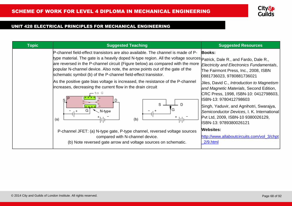
© 2014 City and Guilds of London Institute. All rights reserved.
Page 68 of 92
SCHEME OF WORK FOR LEVEL 4 DIPLOMA IN MECHANICAL ENGINEERING
UNIT 428 ELECTRICAL PRINCIPLES FOR MECHANICAL ENGINEERING
Topic Suggested Teaching Suggested Resources
P-channel field-effect transistors are also available. The channel is made of P-
type material. The gate is a heavily doped N-type region. All the voltage sources
are reversed in the P-channel circuit (Figure below) as compared with the more
popular N-channel device. Also note, the arrow points out of the gate of the
schematic symbol (b) of the P-channel field-effect transistor.
As the positive gate bias voltage is increased, the resistance of the P-channel
increases, decreasing the current flow in the drain circuit
P-channel JFET: (a) N-type gate, P-type channel, reversed voltage sources
compared with N-channel device.
(b) Note reversed gate arrow and voltage sources on schematic.
Books:
Patrick, Dale R., and Fardo, Dale R.,
Electricity and Electronics Fundamentals,
The Fairmont Press, Inc., 2008, ISBN
0881736023, 9780881736021
Jiles, David C., Introduction to Magnetism
and Magnetic Materials, Second Edition,
CRC Press, 1998, ISBN-10: 0412798603,
ISBN-13: 9780412798603
Singh, Yaduvir, and Agnihotri, Swarajya,
Semiconductor Devices, I. K. International
Pvt Ltd, 2009, ISBN-10 9380026129,
ISBN-13: 9789380026121
Websites:
http://www.allaboutcircuits.com/vol_3/chpt
_2/9.html

© 2014 City and Guilds of London Institute. All rights reserved.
Page 69 of 92
SCHEME OF WORK FOR LEVEL 4 DIPLOMA IN MECHANICAL ENGINEERING
UNIT 428 ELECTRICAL PRINCIPLES FOR MECHANICAL ENGINEERING
Lesson 25: Amplifiers Suggested Teaching Time: 8 hour
Learning Outcome 5: Understand the properties, principles and applications of basic analogue
components used in electrical machine control
Topic Suggested Teaching Suggested Resources
Amplifiers
(AC 5.5)
The practical benefit of active devices is their amplifying ability. Whether the
device in question be voltage-controlled or current-controlled, the amount of
power required of the controlling signal is typically far less than the amount of
power available in the controlled current.
In other words, an active device doesn't just allow electricity to control electricity;
it allows a small amount of electricity to control a large amount of electricity.
Because of this disparity between controlling and controlled powers, active
devices may be employed to govern a large amount of power (controlled) by the
application of a small amount of power (controlling). This behaviour is known as
amplification.
The law of conservation of energy is not violated because the additional power
is supplied by an external source, usually a DC battery or equivalent. The
amplifier neither creates nor destroys energy, but merely reshapes it into the
waveform desired.
There are many forms of electronic circuits classed as amplifiers, from
operational amplifiers and small signal amplifiers up to large signal and power
amplifiers.
The classification of an amplifier depends upon the size of the signal, large or
small, its physical configuration and how it processes the input signal, the
relationship between the input signal and the current flowing in the load.
Books:
Patrick, Dale R., and Fardo, Dale R.,
Electricity and Electronics Fundamentals,
The Fairmont Press, Inc., 2008, ISBN
0881736023, 9780881736021
Jiles, David C., Introduction to Magnetism
and Magnetic Materials, Second Edition,
CRC Press, 1998, ISBN-10: 0412798603,
ISBN-13: 9780412798603
Singh, Yaduvir, and Agnihotri, Swarajya,
Semiconductor Devices, I. K. International
Pvt Ltd, 2009, ISBN-10 9380026129,
ISBN-13: 9789380026121
Websites:
http://www.allaboutcircuits.com/vol_3/chpt
_1/5.html

© 2014 City and Guilds of London Institute. All rights reserved.
Page 70 of 92
SCHEME OF WORK FOR LEVEL 4 DIPLOMA IN MECHANICAL ENGINEERING
UNIT 428 ELECTRICAL PRINCIPLES FOR MECHANICAL ENGINEERING
Gain
(AC 5.5)
Because amplifiers have the ability
to increase the magnitude of an
input signal, it is useful to be able to
rate an amplifier's amplifying ability
in terms of an output/input ratio. The
technical term for an amplifier's
output/input magnitude ratio is gain.
As a ratio of equal units (power out /
power in, voltage out / voltage in, or
current out / current in), gain is
naturally a unit less measurement.
Mathematically, gain is symbolised
by the capital letter ‘A’.
Electrical amplifier gains may be expressed in terms of voltage, current, and/or
power, in both AC and DC. A summary of gain definitions is as follows.
The triangle-shaped ‘delta’ symbol (Δ) represents change in mathematics, so
‘ΔVoutput / ΔVinput’ means ‘change in output voltage divided by change in input
voltage,’ or more simply, ‘AC output voltage divided by AC input voltage’:

© 2014 City and Guilds of London Institute. All rights reserved.
Page 71 of 92
SCHEME OF WORK FOR LEVEL 4 DIPLOMA IN MECHANICAL ENGINEERING
UNIT 428 ELECTRICAL PRINCIPLES FOR MECHANICAL ENGINEERING
Topic Suggested Teaching Suggested Resources
Units of
measurement
(AC 5.5)
In its simplest form, an amplifier's gain is a ratio of
output over input. Like all ratios, this form of gain is
unit less. However, there is an actual unit intended
to represent gain, and it is called the bel. Originally,
the bel represented the amount of signal power loss
due to resistance over a standard length of
electrical cable. Now, it is defined in terms of the
common (base 10) logarithm of a power ratio (output power divided by input
power):
Another reason for the adoption of the bel as a unit for gain is for simple
expression of system gains and losses. Where two amplifiers are connected in
tandem to amplify a signal. The respective gain for each amplifier is expressed
as a ratio, and the overall gain for the system will be the product (multiplication)
of those two ratios:
If these figures represented power gains, we could directly apply the unit of bels
to the task of representing the gain of each amplifier, and of the system
altogether
Books:
Dale R Patrick, Dale R., and Fardo, Dale
R., Electricity and Electronics
Fundamentals, The Fairmont Press, Inc.,
2008, ISBN 0881736023, 9780881736021
Jiles, David C., Introduction to Magnetism
and Magnetic Materials, Second Edition,
CRC Press, 1998, ISBN-10: 0412798603,
ISBN-13: 9780412798603
Singh, Yaduvir, and Agnihotri, Swarajya,
Semiconductor Devices, I. K. International
Pvt Ltd, 2009, ISBN-10 9380026129,
ISBN-13: 9789380026121
Websites:
http://www.allaboutcircuits.com/vol_3/chpt
_1/5.html
http://www3.eng.cam.ac.uk/DesignOffice/
mdp/electric_web/Semi/SEMI_1.html

© 2014 City and Guilds of London Institute. All rights reserved.
Page 72 of 92
SCHEME OF WORK FOR LEVEL 4 DIPLOMA IN MECHANICAL ENGINEERING
UNIT 428 ELECTRICAL PRINCIPLES FOR MECHANICAL ENGINEERING
Close inspection of these gain figures in the unit of bel yields a discovery:
they're additive. In this example: 0.477 B + 0.699 B = 1.176 B. Ratio gain figures
are multiplicative for staged amplifiers, but gains expressed in bels add rather
than multiply to equal the overall system gain.
Because the bel is fundamentally a unit of power gain or loss in a system,
voltage or current gains and losses don't convert to bels or dB in quite the same
way. When using bels or decibels to express a gain other than power, be it
voltage or current, we must perform the calculation in terms of how much power
gain there would be for that amount of voltage or current gain. For a constant
load impedance, a voltage or current gain of 2 equates to a power gain of 4
(22); a voltage or current gain of 3 equates to a power gain of 9 (32). If we
multiply either voltage or current by a given factor, then the power gain incurred
by that multiplication will be the square of that factor. This relates back to the
forms of Joule's law where power was calculated from either voltage or current,
and resistance:
𝑃 =𝐸2
𝑅 𝑃 = 𝐼2𝑅 Power is proportional to the square of either voltage or current

© 2014 City and Guilds of London Institute. All rights reserved.
Page 73 of 92
SCHEME OF WORK FOR LEVEL 4 DIPLOMA IN MECHANICAL ENGINEERING
UNIT 428 ELECTRICAL PRINCIPLES FOR MECHANICAL ENGINEERING
Topic Suggested Teaching Suggested Resources
Impedence
(AC 5.5)
Impedance is a comprehensive expression of any and all forms of opposition to
electron flow, including both resistance and reactance. It is present in all
circuits, and in all components. When alternating current goes through an
impedance, a voltage drop is produced that is somewhere between 0o and 90o
out of phase with the current. Impedance is mathematically symbolised by the
letter ‘Z’ and is measured in the unit of ohms (Ω), in complex form.
Books:
Patrick, Dale R., and Fardo, Dale R.,
Electricity and Electronics Fundamentals,
The Fairmont Press, Inc., 2008, ISBN
0881736023, 9780881736021
Jiles, David C., Introduction to Magnetism
and Magnetic Materials, Second Edition,
CRC Press, 1998, ISBN-10: 0412798603,
ISBN-13: 9780412798603
Singh, Yaduvir, and Agnihotri, Swarajya,
Semiconductor Devices, I. K. International
Pvt Ltd, 2009, ISBN-10 9380026129,
ISBN-13: 9789380026121
Websites:
http://www.allaboutcircuits.com/vol_3/chpt
_1/5.html
http://www.electronics-
tutorials.ws/amplifier/input-impedance-of-
an-amplifier.html
Input Impedance, Zin or input resistance as it is also called, is an important
parameter in the design of a transistor amplifier and as such allows amplifiers to
be characterised according to their effective input and output impedances as
well as their power and current ratings. An amplifiers impedance value is
particularly important for analysis especially when cascading individual amplifier
stages together one after another to minimise distortion of the signal.
The input impedance of an amplifier is the input impedance ‘seen’ by the source
driving the input of the amplifier. If it is too low, it can have an adverse loading
effect on the previous stage and possibly affecting the frequency response and
output signal level of that stage. But in most applications, common emitter and
common collector amplifier circuits generally have high input impedances.
Some types of amplifier designs, such as the common collector amplifier circuit
automatically have high input impedance and low output impedance by the very
nature of their design.
In addition to voltage amplification (Av), an amplifier circuit must also have
current amplification (AI). Power amplification (AP) can also be expected from an

© 2014 City and Guilds of London Institute. All rights reserved.
Page 74 of 92
SCHEME OF WORK FOR LEVEL 4 DIPLOMA IN MECHANICAL ENGINEERING
UNIT 428 ELECTRICAL PRINCIPLES FOR MECHANICAL ENGINEERING
amplifier circuit. But as well as having these three important characteristics, an
amplifier circuit must also have other characteristics like high input impedance
(Zin), low output impedance (Zout) and some degree of bandwidth, (Bw). Either
way, the ‘perfect’ amplifier will have infinite input impedance and zero output
impedance.
Attenuators
(AC 5.5)
Attenuators are passive devices. Attenuators weaken or attenuate the high level
output of a signal generator, for example, to provide a lower level signal for
something like the antenna input of a sensitive radio receiver. (Figure below)
The attenuator could be built into the signal generator, or be a stand-alone
device. It could provide a fixed or adjustable amount of attenuation. An
attenuator section can also provide isolation between a source and a
troublesome load.
Attenuator sections can be cascaded for more attenuation than may be
available from a single section. For example two 10 dB attenuators may be
cascaded to provide 20 dB of attenuation, the dB values being additive.

© 2014 City and Guilds of London Institute. All rights reserved.
Page 75 of 92
SCHEME OF WORK FOR LEVEL 4 DIPLOMA IN MECHANICAL ENGINEERING
UNIT 428 ELECTRICAL PRINCIPLES FOR MECHANICAL ENGINEERING
Lesson 26: Electronic noise Suggested Teaching Time: 4 hour
Learning Outcome 5: Understand the properties, principles and applications of basic analogue
components used in electrical machine control
Topic Suggested Teaching Suggested Resources
Thermal noise
(AC 5.6)
Thermal noise is due to thermal agitation of electrons in a conductor. It is
present in all electronic devices and transmission media and is a function of
temperature. Thermal noise is uniformly distributed across the frequency
spectrum and hence is often referred to as white noise; it cannot be eliminated
Books:
Patrick, Dale R., and Fardo, Dale R.,
Electricity and Electronics Fundamentals,
The Fairmont Press, Inc., 2008, ISBN
0881736023, 9780881736021
Jiles, David C., Introduction to Magnetism
and Magnetic Materials, Second Edition,
CRC Press, 1998, ISBN-10: 0412798603,
ISBN-13: 9780412798603
Carter, Bruce, and Mancini, Roy, Op
Amps for Everyone, Newnes (Elsevier)
2009, ISBN: 978-1-85617-505-0
Singh, Yaduvir, and Agnihotri, Swarajya,
Semiconductor Devices, I. K. International
Pvt Ltd, 2009, ISBN-10 9380026129,
ISBN-13: 9789380026121
Websites:
http://www.ti.com/lit/an/slva043b/slva043b
Intermediation
noise
Intermediation noise is produced when there is some non-linearity in the
transmitter, receiver, or intervening transmission system. Normally, these
components behave as linear systems; that is, the output is equal to the input,
times a constant. In a nonlinear system, the output is a more complex function
of the input. Such non linearity can be caused by component malfunction or the
use of excessive signal strength. It is under these circumstances that the sum
and difference terms occur
Shot noise The name ‘shot noise’ is short for Schottky noise (or ‘quantum noise’). This is caused by random fluctuations in the motion of charge carriers in a conductor. In other words, current flow is not a continuous effect. Current flow is electrons, charged particles that move in accordance with an applied potential. When the electrons encounter a barrier, potential energy builds until they have enough energy to cross that barrier. When they have enough potential energy, it is abruptly transformed into kinetic energy as they cross the barrier. As each electron randomly crosses a potential barrier, such as a p-n junction in a semiconductor, energy is stored and released as the electron encounters and then shoots across the barrier. Each electron contributes a little pop as its stored energy is released when it crosses the barrier

© 2014 City and Guilds of London Institute. All rights reserved.
Page 76 of 92
SCHEME OF WORK FOR LEVEL 4 DIPLOMA IN MECHANICAL ENGINEERING
UNIT 428 ELECTRICAL PRINCIPLES FOR MECHANICAL ENGINEERING
Burst noise Burst noise, also called popcorn noise, is related to imperfections in
semiconductor material and heavy ion implants. It is characterised by discrete
high-frequency pulses. The pulse rates may vary, but the amplitudes remain
constant at several times the thermal noise amplitude. Burst noise makes a
popping sound at rates below 100 Hz when played through a speaker; it sounds
like popcorn popping, hence the name.
http://qooljaq.com/OpAmps.htm
Avalanche noise Avalanche noise is created when a p-n junction is operated in the reverse
breakdown mode. Under the influence of a strong reverse electric field within
the junction’s depletion region, electrons have enough kinetic energy that, when
they collide with the atoms of the crystal lattice, additional electron-hole pairs
are formed. These collisions are purely random and produce random current
pulses similar to shot noise, but much more intense
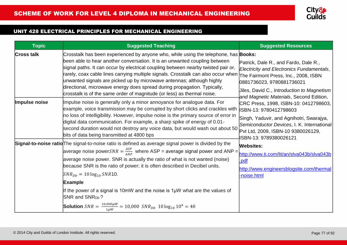
© 2014 City and Guilds of London Institute. All rights reserved.
Page 77 of 92
SCHEME OF WORK FOR LEVEL 4 DIPLOMA IN MECHANICAL ENGINEERING
UNIT 428 ELECTRICAL PRINCIPLES FOR MECHANICAL ENGINEERING
Topic Suggested Teaching Suggested Resources
Cross talk Crosstalk has been experienced by anyone who, while using the telephone, has
been able to hear another conversation. It is an unwanted coupling between
signal paths. It can occur by electrical coupling between nearby twisted pair or,
rarely, coax cable lines carrying multiple signals. Crosstalk can also occur when
unwanted signals are picked up by microwave antennas; although highly
directional, microwave energy does spread during propagation. Typically,
crosstalk is of the same order of magnitude (or less) as thermal noise.
Books:
Patrick, Dale R., and Fardo, Dale R.,
Electricity and Electronics Fundamentals,
The Fairmont Press, Inc., 2008, ISBN
0881736023, 9780881736021
Jiles, David C., Introduction to Magnetism
and Magnetic Materials, Second Edition,
CRC Press, 1998, ISBN-10: 0412798603,
ISBN-13: 9780412798603
Singh, Yaduvir, and Agnihotri, Swarajya,
Semiconductor Devices, I. K. International
Pvt Ltd, 2009, ISBN-10 9380026129,
ISBN-13: 9789380026121
Websites:
http://www.ti.com/lit/an/slva043b/slva043b
http://www.engineersblogsite.com/thermal
-noise.html
Impulse noise Impulse noise is generally only a minor annoyance for analogue data. For
example, voice transmission may be corrupted by short clicks and crackles with
no loss of intelligibility. However, impulse noise is the primary source of error in
digital data communication. For example, a sharp spike of energy of 0.01-
second duration would not destroy any voice data, but would wash out about 50
bits of data being transmitted at 4800 bps
Signal-to-noise ratio The signal-to-noise ratio is defined as average signal power is divided by the
average noise power𝑆𝑁𝑅 =𝐴𝑆𝑃
𝐴𝑁𝑃 where ASP = average signal power and ANP =
average noise power. SNR is actually the ratio of what is not wanted (noise)
because SNR is the ratio of power; it is often described in Decibel units.
𝑆𝑁𝑅𝐷𝑏 = 10 log10 𝑆𝑁𝑅10.
Example
If the power of a signal is 10mW and the noise is 1μW what are the values of
SNR and SNRDb ?
Solution 𝑆𝑁𝑅 = 10,000𝜇𝑊
1𝜇𝑊= 10,000 𝑆𝑁𝑅𝐷𝑏 10 log10 104 = 40

© 2014 City and Guilds of London Institute. All rights reserved.
Page 78 of 92
SCHEME OF WORK FOR LEVEL 4 DIPLOMA IN MECHANICAL ENGINEERING
UNIT 428 ELECTRICAL PRINCIPLES FOR MECHANICAL ENGINEERING
Lesson 27: Logic circuits Suggested Teaching Time: 6 hour
Learning Outcome 6: Understand the properties, principles and applications of basic logic
devices used in electrical machine control
Topic Suggested Teaching Suggested Resources
Evaluating the
function of logic
gates (AC 6.1)
Tutor to draw a lamp circuit with two switches, where either of the switches will
operate the lamp.
Tutor to get the students to discuss how they can turn a light on: lead towards
answer that switch A or switch B will turn the light on.
Tutor to introduce concept of a truth table where a 0 represents off (or not true)
and a 1 represents on (or true).
Tutor to get students to discuss and complete the truth table for this circuit.
Tutor to draw a circuit where both switches have to be made tutor to get the
students to discuss how they can turn a light on: lead towards answer that both
switch A and switch B need to be on to turn the light on.
Books:
Marcovitz, Alan B., Introduction to Logic
and Computer Design, McGraw Hill HE,
ISBN-13: 978-0071285988 ISBN-10:
0071285989
Websites:
http://www.tutorialspoint.com/computer_lo
gical_organization/logic_gates.htm
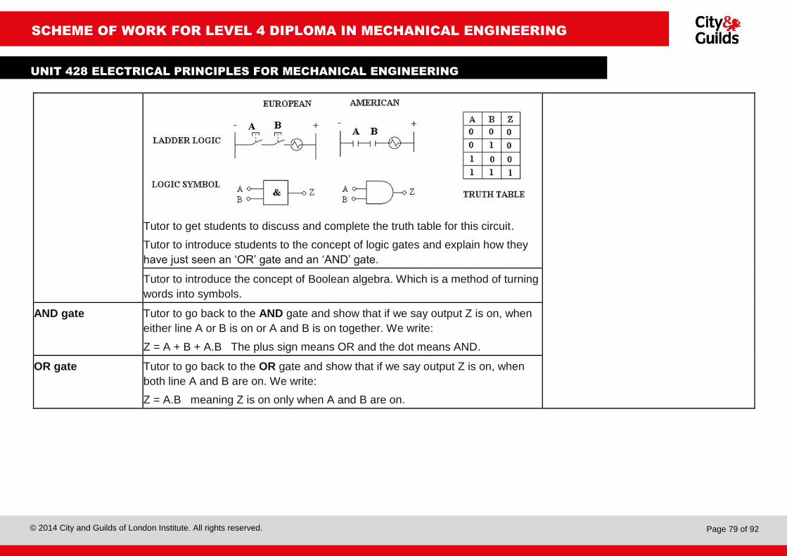
© 2014 City and Guilds of London Institute. All rights reserved.
Page 79 of 92
SCHEME OF WORK FOR LEVEL 4 DIPLOMA IN MECHANICAL ENGINEERING
UNIT 428 ELECTRICAL PRINCIPLES FOR MECHANICAL ENGINEERING
Tutor to get students to discuss and complete the truth table for this circuit.
Tutor to introduce students to the concept of logic gates and explain how they
have just seen an ‘OR’ gate and an ‘AND’ gate.
Tutor to introduce the concept of Boolean algebra. Which is a method of turning
words into symbols.
AND gate Tutor to go back to the AND gate and show that if we say output Z is on, when
either line A or B is on or A and B is on together. We write:
Z = A + B + A.B The plus sign means OR and the dot means AND.
OR gate Tutor to go back to the OR gate and show that if we say output Z is on, when
both line A and B are on. We write:
Z = A.B meaning Z is on only when A and B are on.

© 2014 City and Guilds of London Institute. All rights reserved.
Page 80 of 92
SCHEME OF WORK FOR LEVEL 4 DIPLOMA IN MECHANICAL ENGINEERING
UNIT 428 ELECTRICAL PRINCIPLES FOR MECHANICAL ENGINEERING
Topic Suggested Teaching Suggested Resources
NOT gate
Tutor to draw a circuit with a spring loaded switch that is normally on and a
lamp,
Tutor to get the students to discuss what happens if we press the switch this
time: the light goes out, get the students to complete a truth table for this circuit,
tutor to explain that this is called a not gate
The Boolean statement is either Z = A̅ or Z̅ = A
The over score indicates low or off.
An O added to any
input terminal
inverts that signal
and makes it a not
gate (i.e. normally
on).
Books:
Marcovitz, Alan B., Introduction to Logic
and Computer Design, McGraw Hill HE,
ISBN-13: 978-0071285988 ISBN-10:
0071285989
Websites:
http://www.tutorialspoint.com/computer_lo
gical_organization/logic_gates.htm

© 2014 City and Guilds of London Institute. All rights reserved.
Page 81 of 92
SCHEME OF WORK FOR LEVEL 4 DIPLOMA IN MECHANICAL ENGINEERING
UNIT 428 ELECTRICAL PRINCIPLES FOR MECHANICAL ENGINEERING
Exclusive OR (XOR)
Tutor to draw a circuit where there are two parallel paths with switch A having a
component in both lines one normally made and one normally open and switch
B having the same layout but where A is normally open B must be normally
closed.
Tutor to get the students to discuss what happens if we press the switches this
time. Lead them to the conclusion that the light is on when A or B is on but off
when both are on; get the students to complete a truth table for this circuit
The Boolean statement is: Z = A + B which means Z is on when A is on and B is
off or when A is off and B is on (tutor to point out that there is no +A.B at the end
like there was on the AND gate).
NAND gate Tutor to go
back to the not
gate and add a
parallel path
way with
another

© 2014 City and Guilds of London Institute. All rights reserved.
Page 82 of 92
SCHEME OF WORK FOR LEVEL 4 DIPLOMA IN MECHANICAL ENGINEERING
UNIT 428 ELECTRICAL PRINCIPLES FOR MECHANICAL ENGINEERING
normally on switch. Tutor to show similarity to an and switch. However this time
the light is normally on until you press switch A and B together when it will go
out: tutor to get the students to complete a truth table for this circuit.
This is known as a NAND switch (not and)
The Boolean statement is: Z̅ = A.B meaning Z is Off when A and B are both on.
Topic Suggested Teaching Suggested Resources
NOR gate
Tutor to draw a lamp circuit with a pair of normally closed switches in series.
Tutor to get the students to discuss what happens if we press the switches this
time. If necessary help them reach the conclusion that the light is on until either
switch A or B is pressed, get the students to complete a truth table for this
circuit.
The Boolean statement is: 𝑍 = A̅ + B̅
Books:
Marcovitz, Alan B., Introduction to Logic
and Computer Design, McGraw Hill HE,
ISBN-13: 978-0071285988 ISBN-10:
0071285989
Websites:
http://www.tutorialspoint.com/computer_lo
gical_organization/logic_gates.htm

© 2014 City and Guilds of London Institute. All rights reserved.
Page 83 of 92
SCHEME OF WORK FOR LEVEL 4 DIPLOMA IN MECHANICAL ENGINEERING
UNIT 428 ELECTRICAL PRINCIPLES FOR MECHANICAL ENGINEERING
Multile inputs Tutor t introduce the concept that logic gates can
have more than two inputs
This one has three inputs so the output Z is turned
on when A and B and C is turned on
Combining logic
gates – an
introduction
Tutor to give a quick introduction as to how these gates could be used together
in a more complex logic circuit is shown below with four inputs.
The truth table is shown with only the conditions for turning the output on.
The pattern of the inputs can be interpreted as a digital number.
There are three possible combinations that can turn the output on.
The three digital numbers that will turn the output on are hence 14, 1 and 15.
(With A forming the most significant bit).
If A, B, C and D were connected to a computer data bus then the computer
could switch the output on when it recognises these numbers.

© 2014 City and Guilds of London Institute. All rights reserved.
Page 84 of 92
SCHEME OF WORK FOR LEVEL 4 DIPLOMA IN MECHANICAL ENGINEERING
UNIT 428 ELECTRICAL PRINCIPLES FOR MECHANICAL ENGINEERING
Lesson 28: Logic families Suggested Teaching Time: 1 hour
Learning Outcome 6: Understand the properties, principles and applications of basic logic
devices used in electrical machine control
Topic Suggested Teaching Suggested Resources
Evaluating the
principal
characteristics of
different logic
families
(AC 6.2)
Tutor to get the students to do a research project on the different logic families
Getting them to cover factors such as:
Speed
Power
Cost
Interface requirements (propagation delay).
for the following types:
Complementary metal oxide – semiconductor (CMOS)
Transistor-transistor logic (TTL)
ECL
BiCMOS
Books:
Marcovitz, Alan B., Introduction to Logic
and Computer Design, McGraw Hill HE,
ISBN-13: 978-0071285988, ISBN-10:
0071285989

© 2014 City and Guilds of London Institute. All rights reserved.
Page 85 of 92
SCHEME OF WORK FOR LEVEL 4 DIPLOMA IN MECHANICAL ENGINEERING
UNIT 428 ELECTRICAL PRINCIPLES FOR MECHANICAL ENGINEERING
Lesson 29: Logic families Suggested Teaching Time: 8hour
Learning Outcome 6: Understand the properties, principles and applications of basic logic
devices used in electrical machine control
Topic Suggested Teaching Suggested Resources
Operation of
combinational logic
circuits
(AC 6.3)
Whole-class discussion to recap the lessons learned about logic gates and how
they can be combined.
Tutor to demonstrate using Boolean expressions and truth tables how these
gates work together.
Explain the difference between:
Half adders and full adders
Multiplexers and demultiplexers
Half subtractors and full subtractors
Encoders and decoders
Explain that a comparator is a device that compares two voltages or currents
and outputs a digital signal indicating which is larger.
Books:
Marcovitz, Alan B., Introduction to Logic
and Computer Design, McGraw Hill HE,
ISBN-13: 978-0071285988 ISBN-10:
0071285989
Websites:
http://www.tutorialspoint.com/computer_lo
gical_organization/logic_gates.htm
http://www.tutorialspoint.com/computer_lo
gical_organization/combinational_circuits.
htm
http://eshare.stust.edu.tw/EshareFile/2011
_4/2011_4_d4f0ae35.pdf Tutor to discuss how it is important to check that data has been transmitted and
received correctly and the use of parity checkers and generators.

© 2014 City and Guilds of London Institute. All rights reserved.
Page 86 of 92
SCHEME OF WORK FOR LEVEL 4 DIPLOMA IN MECHANICAL ENGINEERING
UNIT 428 ELECTRICAL PRINCIPLES FOR MECHANICAL ENGINEERING
Lesson 30: Large electrical motors Suggested Teaching Time: 1 hours
Learning Outcome 7: Understand the principles of controlling large industrial electric motors
Topic Suggested Teaching Suggested Resources
Assess attributes of
different types of
motor starters for
three-phase
squirrel-cage
induction motors
(AC 7.1)
Tutor-led discussion to recap AC motors and to recap advantages and
disadvantages of three-phase motors
If the coils are connected in a star formation, the current flowing through them is
the phase current. If the coils are connected in the delta formation, the current
flowing through them is the line current.
Suppose we had a three-phase motor supplied with 415 V and 17.3 A (line
values). If the motor is connected in delta formation we have 17.3 A in each coil
and 415 V over each. If we connect it in star formation we get 17.3/√3 = 10 A in
each coil and √3 x 415 = 240 V over each.
Three-phase motors running normally have their field coils connected in the
DELTA fashion. Because of the high currents drawn on starting when the
induction effect is greatest, the coils are connected in the star formation and
then changed to the delta formation when it has accelerated close to its running
speed. Note that the starting torque is also reduced in star formation but this is
usually sufficient to run the motor up to speed.
The change from Star to Delta is normally achieved by external switching and
this is commonly referred to as a soft starter or a Star Delta starter. This is
simply a number of contactors (switches) that connect the different leads
together to form the required connection, i.e. Star or Delta. These use a specific
starting sequence with timers to switch between Star and Delta.
Books:
Hughes, Austin, Electric Motors and
Drives: Fundamentals, Types and
Applications, 4th edition, Newnes, 2013,
ISBN-10: 0080983324, ISBN-13: 978-
0080983325
Practical Equipment:
Three-phase motor and test equipment
Websites:
http://www.electrical4u.com
http://www.freestudy.co.uk/further%20elpri
nc%20unit67/outcome4t1.pdf

© 2014 City and Guilds of London Institute. All rights reserved.
Page 87 of 92
SCHEME OF WORK FOR LEVEL 4 DIPLOMA IN MECHANICAL ENGINEERING
UNIT 428 ELECTRICAL PRINCIPLES FOR MECHANICAL ENGINEERING
Lesson 31: Silicon controlled rectifiers Suggested Teaching Time: 2 hours
Learning Outcome 7: Understand the principles of controlling large industrial electric motors
Topic Suggested Teaching Suggested Resources
Operating principle of
the silicon
controlled rectifier
SCR
(AC 7.2)
A silicon controlled rectifier (SCR) works in a similar fashion to a typical diode,
but is controlled similar to a bipolar transistor as far as connections go. It has
three connection points: anode [A], cathode [K], and gate [G].
The SCR is made up of two p-n junctions with a gate attachment between them
(a normal diode [power type semiconductor diode] has one p-n junction). The
gate is connected between the two p-n junctions with a current waiting in the
forward bias direction [+ to -] and the voltage is above 1-volt.
A momentary pulse to the gate will cause the SCR to conduct and current will
flow across the device until the value changes. If this happens, the gate needs
to be pulsed again to cause conduction to resume; otherwise no current will flow
across the device.
If used on AC, the device needs to be triggered [fired] in relationship to the
points on the sine wave that conduction is requested. Example: to chop a wave
to be 1/2 peak, the SCR gate will need to be pulsed with either a high-logic
pulse or a positive-voltage pulse until the AC wave reaches 50% of peak value
in the positive flowing direction.
Books:
Hughes, Austin, Electric Motors and
Drives: Fundamentals, Types and
Applications, 4th edition, Newnes, 2013,
ISBN-10: 0080983324, ISBN-13: 978-
0080983325
Practical Equipment:
Electric motor, SCR and test equipment
Websites:
http://www.electrical4u.com

© 2014 City and Guilds of London Institute. All rights reserved.
Page 88 of 92
SCHEME OF WORK FOR LEVEL 4 DIPLOMA IN MECHANICAL ENGINEERING
UNIT 428 ELECTRICAL PRINCIPLES FOR MECHANICAL ENGINEERING
Topic Suggested Teaching Suggested Resources
How precise speed
control of a DC
motor can be
achieved using an
SCR and a suitable
feedback signal
(A.C.7.3)
When a SCR device is connected in series with load circuit, the load current
will flow through the device from anode (A) to cathode (K), but this load current
will be controlled by the gate (G) signal applied to the device externally.
A thyristor is an on-off switch which is used to control output power of an
electrical circuit by switching on and off the load circuit periodically in a preset
interval.
The main difference between thyristors and other digital and electronics
switches is that a thyristor can handle more larger electric current and can
withstand larger voltage than the others.
Books:
Hughes, Austin, Electric Motors and
Drives: Fundamentals, Types and
Applications, 4th edition, Newnes, 2013,
ISBN-10: 0080983324, ISBN-13: 978-
0080983325
Subrahmanyam, Vedam, Thyristor
Control of Electric Drives, Tata McGraw-
Hill Education, 1988, ISBN 0074603418,
9780074603413
Practical Equipment:
Electric motor, SCR and test equipment
Websites:
http://www.electrical4u.com/thyristor-
silicon-controlled-rectifier/
http://www.eetimes.com/document.asp?d
oc_id=1274114

© 2014 City and Guilds of London Institute. All rights reserved.
Page 89 of 92
SCHEME OF WORK FOR LEVEL 4 DIPLOMA IN MECHANICAL ENGINEERING
UNIT 428 ELECTRICAL PRINCIPLES FOR MECHANICAL ENGINEERING
The controlled (thyristor) rectifier provides a low-impedance adjustable DC
voltage for the motor armature, thereby providing speed control.
For motors up to a few kilowatts, the armature converter can be supplied from
either single-phase or three-phase mains, but for larger motors three-phase is
always used. A separate thyristor or diode rectifier is used to supply the field of
the motor: the power is much less than the armature power, so the supply is
often single-phase, as shown in the diagram of a DC-controlled motor-drive
shown above.
The arrangement shown is typical of the majority of DC drives and provides for
closed-loop speed control.
Low power control circuits are used to monitor the principal variables of interest
(usually motor current and speed), and to generate appropriate firing pulses so
that the motor maintains constant speed despite variations in the load.
The 'speed reference' (diagram above) is typically an analogue voltage varying
from 0 to 10 V, and obtained from a manual speed-setting potentiometer or
from elsewhere in the plant.

© 2014 City and Guilds of London Institute. All rights reserved.
Page 90 of 92
SCHEME OF WORK FOR LEVEL 4 DIPLOMA IN MECHANICAL ENGINEERING
UNIT 428 ELECTRICAL PRINCIPLES FOR MECHANICAL ENGINEERING
Lesson 32: Variable frequency drive Suggested Teaching Time: 6 hours
Learning Outcome 7: Understand the principles of controlling large industrial electric motors
Topic Suggested Teaching Suggested Resources
Speed control of a
three-phase
induction motor
using a variable
frequency drive
(A.C.7.4)
A variable frequency drive (VFD) is a type of motor controller that drives an
electric motor by varying the frequency and voltage supplied to the electric
motor. Other names for a VFD are variable speed drive, adjustable speed
drive, adjustable frequency drive, AC drive, microdrive, and inverter.
Frequency (or hertz) is directly related to the motor’s speed (RPMs). In other
words, the faster the frequency, the faster the RPMs go. If an application
does not require an electric motor to run at full speed, the VFD can be used
to ramp down the frequency and voltage to meet the requirements of the
electric motor’s load. As the application’s motor speed requirements change,
the VFD can simply turn up or down the motor speed to meet the speed
requirement.
Books:
Hughes, Austin, Electric Motors and
Drives: Fundamentals, Types and
Applications, 4th edition, Newnes, 2013,
ISBN-10: 0080983324, ISBN-13: 978-
0080983325
Websites:
http://www.vfds.com/blog/what-is-a-vfd
Effects of solid-
state speed
control systems
on different types
of motors (DC, ac)
(A.C.7.5)
The AC electric motor used in a VFD system is usually a three-phase
induction motor. Some types of single-phase motors can be used, but three-
phase motors are usually preferred.
Various types of synchronous motors offer advantages in some situations,
but three-phase induction motors are suitable for most purposes and are
generally the most economical motor choice. Motors that are designed for
fixed-speed operation are often used.
Elevated voltage stresses imposed on induction motors that are supplied by
VFDs require that such motors be designed for definite-purpose inverter-fed
duty.
Books:
Hughes, Austin, Electric Motors and
Drives: Fundamentals, Types and
Applications, 4th edition, Newnes, 2013,
ISBN-10: 0080983324, ISBN-13: 978-
0080983325
Websites:
http://en.wikipedia.org/wiki/Variable-
frequency_drive

© 2014 City and Guilds of London Institute. All rights reserved.
Page 91 of 92
SCHEME OF WORK FOR LEVEL 4 DIPLOMA IN MECHANICAL ENGINEERING
UNIT 428 ELECTRICAL PRINCIPLES FOR MECHANICAL ENGINEERING
Many fixed-speed motor load applications that are supplied direct from AC
line power can save energy when they are operated at variable-speed, by
means of VFD.
Such energy cost savings are especially pronounced in variable-torque
centrifugal fan and pump applications, where the loads' torque and power
vary with the square and cube, respectively, of the speed.
This change gives a large power reduction compared to fixed-speed
operation for a relatively small reduction in speed. For example, at 63%
speed a motor load consumes only 25% of its full speed power.
Load torque and power characteristics
Variable frequency drives are also categorised by the following load torque
and power characteristics:
Variable torque, such as in centrifugal fan, pump and blower
applications
Constant torque, such as in conveyor and positive displacement pump
applications
Constant power, such as in machine tool and traction applications.
http://www.pacontrol.com/download/Adj
ustable-Speed-Drives-Tutorial.pdf

© 2014 City and Guilds of London Institute. All rights reserved.
Page 92 of 92
SCHEME OF WORK FOR LEVEL 4 DIPLOMA IN MECHANICAL ENGINEERING
UNIT 428 ELECTRICAL PRINCIPLES FOR MECHANICAL ENGINEERING
Topic Suggested Teaching Suggested Resources
Effects of solid
state speed control
systems on
different types of
motors (DC, AC)
(AC 7.5)
Tutor to discuss how adjustable speed drives have a number of advantages
and disadvantages compared to other types of variable speed controls
including:
Advantages:
Energy savings
Improved process control
Reduced voltage starting
Lower system maintenance
Bypass capability
Multi-motor control
Disadvantages:
Initial cost
Motor heating at low speeds
Maintenance4. Output harmonics
Induced power line harmonics


![DIPLOMA IN MECHANICAL ENGINEERING [ FOUNDRY ] …](https://img.pdfslide.net/doc/110x75/6205a1113c14e64a7b6ab13e/diploma-in-mechanical-engineering-foundry-.jpg)