Embed Size (px)
Citation preview
Application and Function
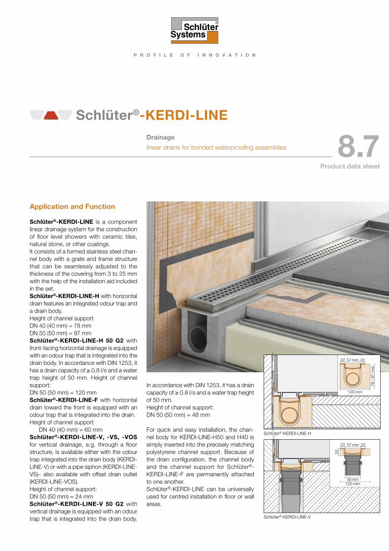
Schlüter®-KERDI-LINE is a component linear drainage system for the construction of floor level showers with ceramic tiles, natural stone, or other coatings. It consists of a formed stainless steel chan-nel body with a grate and frame structure that can be seamlessly adjusted to the thickness of the covering from 3 to 25 mm with the help of the installation aid included in the set. Schlüter®-KERDI-LINE-H with horizontal drain features an integrated odour trap and a drain body.Height of channel support:DN 40 (40 mm) = 78 mmDN 50 (50 mm) = 97 mmSchlüter®-KERDI-LINE-H 50 G2 with front-facing horizontal drainage is equipped with an odour trap that is integrated into the drain body. In accordance with DIN 1253, it has a drain capacity of ≥ 0.8 l/s and a water trap height of 50 mm. Height of channel support:DN 50 (50 mm) = 120 mmSchlüter®-KERDI-LINE-F with horizontal drain toward the front is equipped with an odour trap that is integrated into the drain. Height of channel support: DN 40 (40 mm) = 60 mmSchlüter®-KERDI-LINE-V, -VS, -VOS for vertical drainage, e.g. through a floor structure, is available either with the odour trap integrated into the drain body (KERDI-LINE-V) or with a pipe siphon (KERDI-LINE-VS)– also available with offset drain outlet (KERDI-LINE-VOS).Height of channel support:DN 50 (50 mm) = 24 mmSchlüter®-KERDI-LINE-V 50 G2 with vertical drainage is equipped with an odour trap that is integrated into the drain body.
In accordance with DIN 1253, it has a drain capacity of ≥ 0.8 l/s and a water trap height of 50 mm.Height of channel support:DN 50 (50 mm) = 48 mm
For quick and easy installation, the chan-nel body for KERDI-LINE-H50 and H40 is simply inserted into the precisely matching polystyrene channel support. Because of the drain configuration, the channel body and the channel support for Schlüter®-KERDI-LINE-F are permanently attached to one another.Schlüter®-KERDI-LINE can be universally used for centred installation in floor or wall areas.
Schlüter®-KERDI-LINEDrainage
linear drains for bonded waterproofing assemblies 8.7Product data sheet
120 mm
57 mm
78 /
97
mm
2222
Schlüter®-KERDI-LINE-H
57 mm
24
120 mm
2222
50 mm
Schlüter®-KERDI-LINE-V
8.7 Schlüter®-KERDI-LINE
2
57 mm
78 /
97
mm
137 mm
2222
57 mm22 22
120
mm
137 mm120 mm
57 mm
24
120 mm
2222
50 mm
57 2222
4892
50135 mm
142
192
mm
Schlüter®-KERDI-LINE-H (intermediate installation)
Schlüter®-KERDI-LINE-H 50 G2 (intermediate installation)
Schlüter®-KERDI-LINE-V GE (perimeter installation with odour trap)
Schlüter®-KERDI-LINE-V 50 G2 (intermediate installation)
57 mm
24
137 mm
2222
50 mm
Schlüter®-KERDI-LINE-V GSE (intermediate installation)
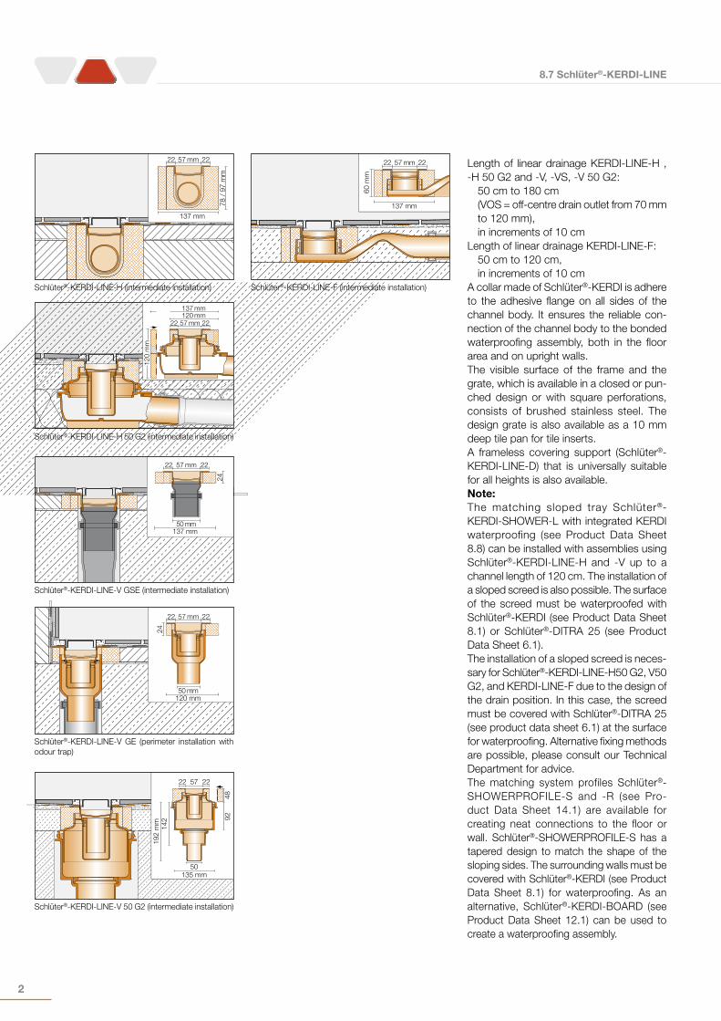
Length of linear drainage KERDI-LINE-H , -H 50 G2 and -V, -VS, -V 50 G2:
50 cm to 180 cm (VOS = off-centre drain outlet from 70 mm to 120 mm),in increments of 10 cm
Length of linear drainage KERDI-LINE-F:50 cm to 120 cm,in increments of 10 cm
A collar made of Schlüter®-KERDI is adhere to the adhesive flange on all sides of the channel body. It ensures the reliable con-nection of the channel body to the bonded waterproofing assembly, both in the floor area and on upright walls.The visible surface of the frame and the grate, which is available in a closed or pun-ched design or with square perforations, consists of brushed stainless steel. The design grate is also available as a 10 mm deep tile pan for tile inserts.A frameless covering support (Schlüter®-KERDI-LINE-D) that is universally suitable for all heights is also available.Note:The matching sloped tray Schlüter®-KERDI-SHOWER-L with integrated KERDI waterproofing (see Product Data Sheet 8.8) can be installed with assemblies using Schlüter®-KERDI-LINE-H and -V up to a channel length of 120 cm. The installation of a sloped screed is also possible. The surface of the screed must be waterproofed with Schlüter®-KERDI (see Product Data Sheet 8.1) or Schlüter®-DITRA 25 (see Product Data Sheet 6.1).The installation of a sloped screed is neces-sary for Schlüter®-KERDI-LINE-H50 G2, V50 G2, and KERDI-LINE-F due to the design of the drain position. In this case, the screed must be covered with Schlüter®-DITRA 25 (see product data sheet 6.1) at the surface for waterproofing. Alternative fixing methods are possible, please consult our Technical Department for advice.The matching system profiles Schlüter®-SHOWERPROFILE-S and -R (see Pro-duct Data Sheet 14.1) are available for creating neat connections to the floor or wall. Schlüter®-SHOWERPROFILE-S has a tapered design to match the shape of the sloping sides. The surrounding walls must be covered with Schlüter®-KERDI (see Product Data Sheet 8.1) for waterproofing. As an alternative, Schlüter®-KERDI-BOARD (see Product Data Sheet 12.1) can be used to create a waterproofing assembly.
137 mm
57 mm
60 m
m
2222
Schlüter®-KERDI-LINE-F (intermediate installation)
8.7 Schlüter®-KERDI-LINE
3
Material
The channel bodies with lengths up to 120 cm are made of formed stainless steel V4A (material no. 1.44404 = AISI 316L). From lengths of 130 cm, they are made of angled and welded stainless steel V4A (material no. 1.44404 = AISI 316L). The channel bodies feature an adhesive flange with a factory-attached Schlüter®-KERDI collar on the surface. This is a soft polyethylene waterproofing membrane with fleece fabric laminated on both sides.Depending on the type, drain bodies are made of high-impact polypropylene (PP) or acrylonitrile butadiene styrene (ABS).The odour trap is made of fibre-reinforced polypropylene (PP).The stainless steel frame and grates consist of V4A (material no. 1.4404 = AISI 316L). The channel support is made of pressure resistant, expanded polystyrene (EPS).
Material properties and areas of application:The channel body, the frame, and the grates are categorised as Class K3 on the basis of DIN EN 1253 (BS EN 1253), Gullies for Buil-dings. These include areas without vehicle traffic, such as wet rooms in apartments, nursing homes, hotels, schools as well as public bathrooms and shower facilities. The channel bodies, frames and grates are desi-gned to withstand the use of wheelchairs. Schlüter®-KERDI-LINE is made of V4A (material no. 1.4404 = AISI 316L), which is particularly suitable for high mechanical impact or special exposure to chemicals.Even stainless steel of quality 1.4404 is not resistant to all chemical stresses, and may be affected, e.g., by hydrochloric and hydrofluoric acid or certain chloride and brine concentrations. In certain cases, this also applies to seawater pools. In special cases, the suitability of the selected floor drainage system must be verified based on the anticipated chemical, mechanical, and/or other stresses. The use of aggressive detergents should be avoided.
Notes
The set includes a special cleaning brush with instructions for easy periodic cleaning of the odour trap and the channel body. All cleaning agents must be free of hydrochloric and hydrofluoric acid. Avoid contact with other metals, such as regular steel, to pre-vent corrosion. This also includes installation tools such as trowels or steel wool, e.g. for the removal of mortar residue. Do not use abrasive cleaning agents on the sensitive surfaces. We recommend the use of the stainless steel cleaning polish Schlüter®-CLEAN-CP.
8.7 Schlüter®-KERDI-LINE
4
Installation
The following steps explain the installation of the linear drainage systems. For detailed descriptions please refer to the installation instructions for the following products:Schlüter®-KERDI-LINE-HSchlüter®-KERDI-LINE-H 50 G2Schlüter®-KERDI-LINE-FSchlüter®-KERDI-LINE-VSchlüter®-KERDI-LINE-V 50 G2Schlüter®-KERDI-LINE-D (covering support)
Installation with low construction height:Schlüter®-KERDI-LINE-H, -H 50 G2 and -F are designed for horizontal drainage to a floor level. Schlüter®-KERDI-LINE-F is par-ticularly well suited for renovation projects due to its low assembly height of just 60 mm. If drainage through a floor level is a pos-sibility, an installation height of ≥ 24 mm can be achieved with Schlüter®-KERDI-LINE-V.
Schlüter®-KERDI-LINE-HHorizontal drain
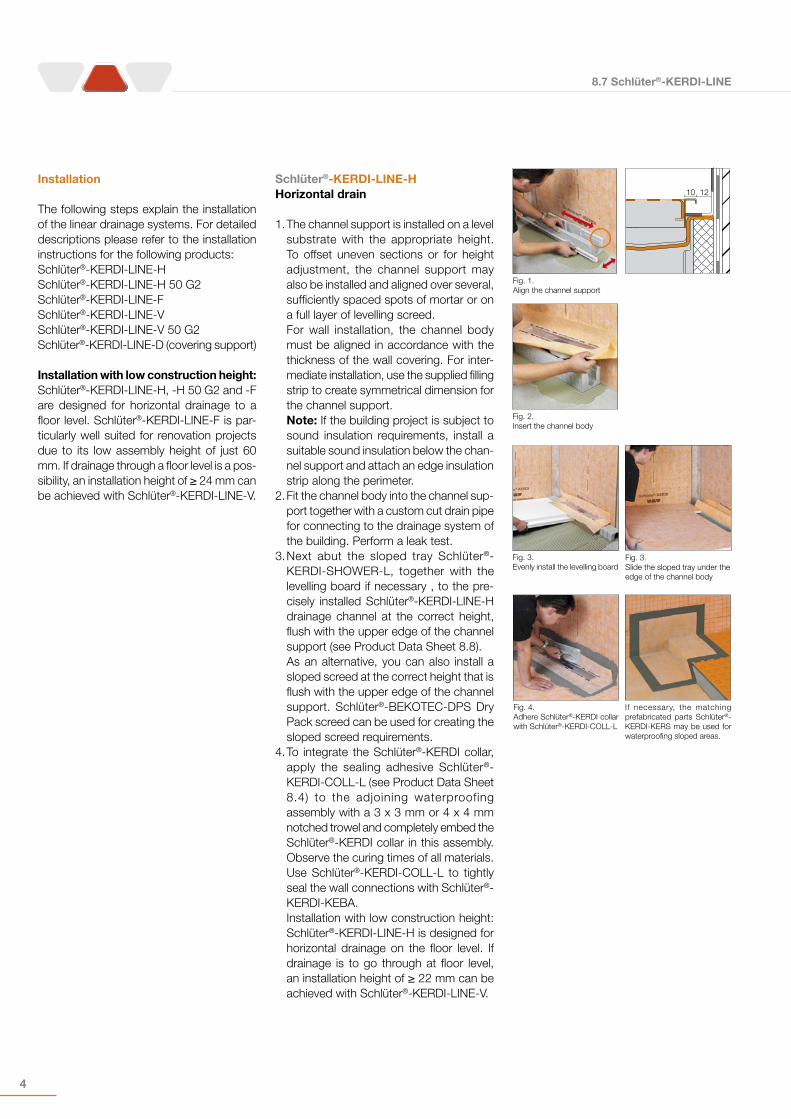
1. The channel support is installed on a level substrate with the appropriate height. To offset uneven sections or for height adjustment, the channel support may also be installed and aligned over several, sufficiently spaced spots of mortar or on a full layer of levelling screed.For wall installation, the channel body must be aligned in accordance with the thickness of the wall covering. For inter-mediate installation, use the supplied filling strip to create symmetrical dimension for the channel support. Note: If the building project is subject to sound insulation requirements, install a suitable sound insulation below the chan-nel support and attach an edge insulation strip along the perimeter.
2. Fit the channel body into the channel sup-port together with a custom cut drain pipe for connecting to the drainage system of the building. Perform a leak test.
3. Next abut the sloped tray Schlüter®-KERDI-SHOWER-L, together with the levelling board if necessary , to the pre-cisely installed Schlüter®-KERDI-LINE-H drainage channel at the correct height, flush with the upper edge of the channel support (see Product Data Sheet 8.8).As an alternative, you can also install a sloped screed at the correct height that is flush with the upper edge of the channel support. Schlüter®-BEKOTEC-DPS Dry Pack screed can be used for creating the sloped screed requirements.
4. To integrate the Schlüter®-KERDI collar, apply the sealing adhesive Schlüter®-KERDI-COLL-L (see Product Data Sheet 8.4) to the adjoining waterproofing assembly with a 3 x 3 mm or 4 x 4 mm notched trowel and completely embed the Schlüter®-KERDI collar in this assembly. Observe the curing times of all materials. Use Schlüter®-KERDI-COLL-L to tightly seal the wall connections with Schlüter®-KERDI-KEBA.Installation with low construction height: Schlüter®-KERDI-LINE-H is designed for horizontal drainage on the floor level. If drainage is to go through at floor level, an installation height of ≥ 22 mm can be achieved with Schlüter®-KERDI-LINE-V.
Fig. 1.Align the channel support
Fig. 2.Insert the channel body
Fig. 3. Evenly install the levelling board
Fig. 4.Adhere Schlüter®-KERDI collar with Schlüter®-KERDI-COLL-L
If necessary, the matching prefabricated parts Schlüter®-KERDI-KERS may be used for waterproofing sloped areas.
Fig. 3. Slide the sloped tray under the edge of the channel body
1210
8.7 Schlüter®-KERDI-LINE
5
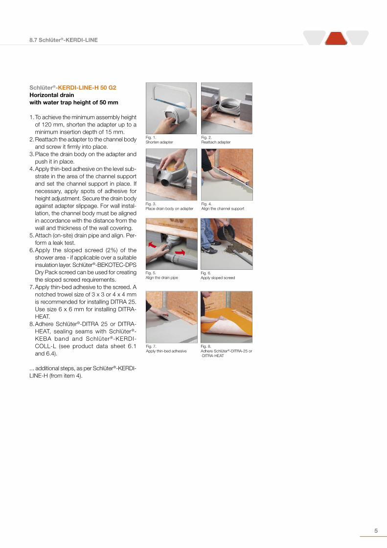
Schlüter®-KERDI-LINE-H 50 G2Horizontal drain with water trap height of 50 mm
1. To achieve the minimum assembly height of 120 mm, shorten the adapter up to a minimum insertion depth of 15 mm.
2. Reattach the adapter to the channel body and screw it firmly into place.
3. Place the drain body on the adapter and push it in place.
4. Apply thin-bed adhesive on the level sub-strate in the area of the channel support and set the channel support in place. If necessary, apply spots of adhesive for height adjustment. Secure the drain body against adapter slippage. For wall instal-lation, the channel body must be aligned in accordance with the distance from the wall and thickness of the wall covering.
5. Attach (on-site) drain pipe and align. Per-form a leak test.
6. Apply the sloped screed (2%) of the shower area - if applicable over a suitable insulation layer. Schlüter®-BEKOTEC-DPS Dry Pack screed can be used for creating the sloped screed requirements.
7. Apply thin-bed adhesive to the screed. A notched trowel size of 3 x 3 or 4 x 4 mm is recommended for installing DITRA 25. Use size 6 x 6 mm for installing DITRA-HEAT.
8. Adhere Schlüter®-DITRA 25 or DITRA-HEAT, sealing seams with Schlüter®-KEBA band and Schlüter®-KERDI-COLL-L (see product data sheet 6.1 and 6.4).
... additional steps, as per Schlüter®-KERDI-LINE-H (from item 4).
Fig. 1.Shorten adapter
Fig. 2.Reattach adapter
Fig. 3.Place drain body on adapter
Fig. 4.Align the channel support
Fig. 5.Align the drain pipe
Fig. 7.Apply thin-bed adhesive
Fig. 6.Apply sloped screed
Fig. 8.Adhere Schlüter®-DITRA-25 or -DITRA-HEAT
8.7 Schlüter®-KERDI-LINE
6
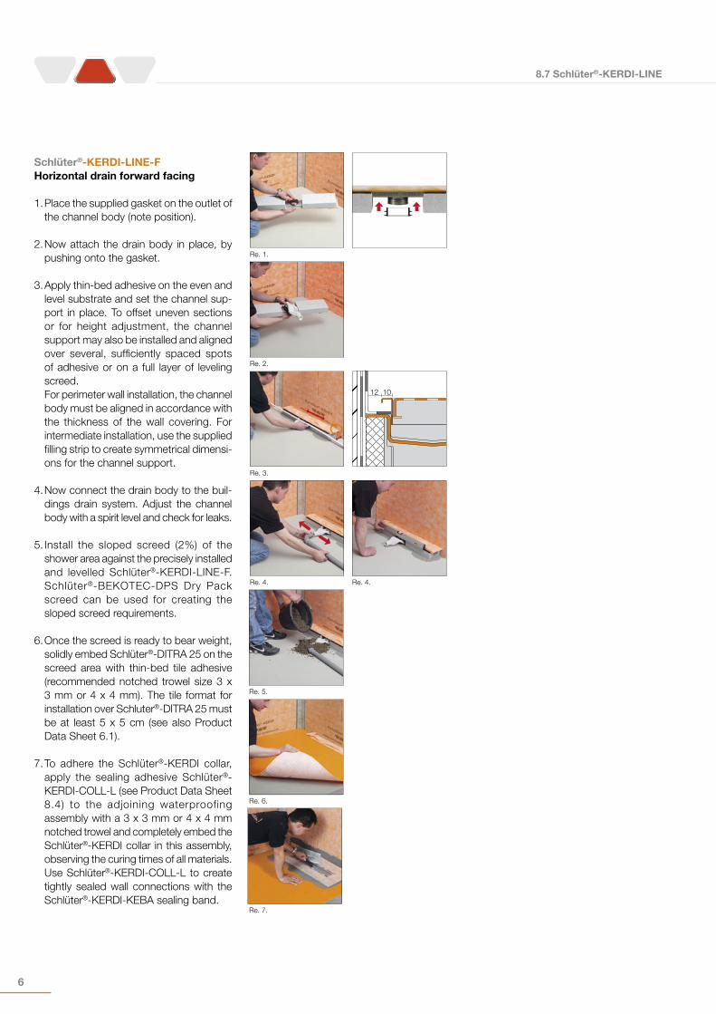
Schlüter®-KERDI-LINE-FHorizontal drain forward facing
1. Place the supplied gasket on the outlet of the channel body (note position).
2. Now attach the drain body in place, by pushing onto the gasket.
3. Apply thin-bed adhesive on the even and level substrate and set the channel sup-port in place. To offset uneven sections or for height adjustment, the channel support may also be installed and aligned over several, sufficiently spaced spots of adhesive or on a full layer of leveling screed.For perimeter wall installation, the channel body must be aligned in accordance with the thickness of the wall covering. For intermediate installation, use the supplied filling strip to create symmetrical dimensi-ons for the channel support.
4. Now connect the drain body to the buil-dings drain system. Adjust the channel body with a spirit level and check for leaks.
5. Install the sloped screed (2%) of the shower area against the precisely installed and levelled Schlüter®-KERDI-LINE-F. Schlüter®-BEKOTEC-DPS Dry Pack screed can be used for creating the sloped screed requirements.
6. Once the screed is ready to bear weight, solidly embed Schlüter®-DITRA 25 on the screed area with thin-bed tile adhesive (recommended notched trowel size 3 x 3 mm or 4 x 4 mm). The tile format for installation over Schluter®-DITRA 25 must be at least 5 x 5 cm (see also Product Data Sheet 6.1).
7. To adhere the Schlüter®-KERDI collar, apply the sealing adhesive Schlüter®-KERDI-COLL-L (see Product Data Sheet 8.4) to the adjoining waterproofing assembly with a 3 x 3 mm or 4 x 4 mm notched trowel and completely embed the Schlüter®-KERDI collar in this assembly, observing the curing times of all materials. Use Schlüter®-KERDI-COLL-L to create tightly sealed wall connections with the Schlüter®-KERDI-KEBA sealing band.
Re. 1.
Re. 3.
Re. 4. Re. 4.
Re. 5.
Re. 6.
Re. 7.
Re. 2.
12 10
8.7 Schlüter®-KERDI-LINE
7
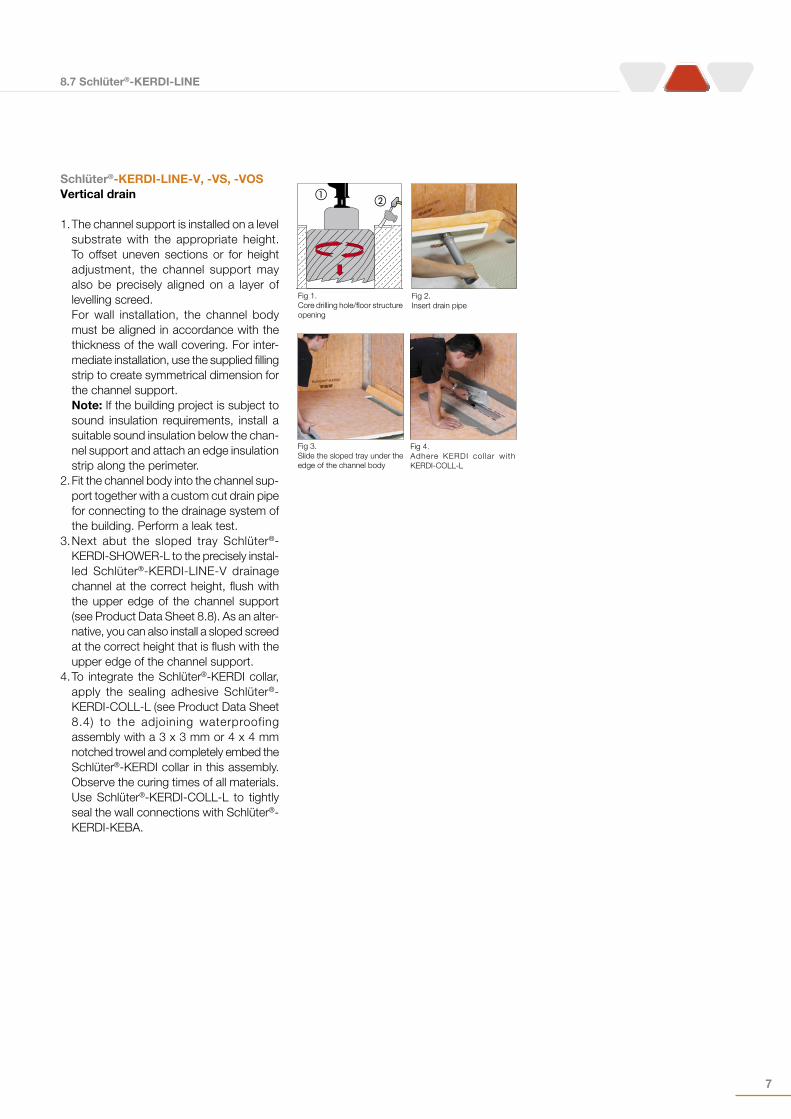
Schlüter®-KERDI-LINE-V, -VS, -VOSVertical drain
1. The channel support is installed on a level substrate with the appropriate height. To offset uneven sections or for height adjustment, the channel support may also be precisely aligned on a layer of levelling screed.For wall installation, the channel body must be aligned in accordance with the thickness of the wall covering. For inter-mediate installation, use the supplied filling strip to create symmetrical dimension for the channel support.Note: If the building project is subject to sound insulation requirements, install a suitable sound insulation below the chan-nel support and attach an edge insulation strip along the perimeter.
2. Fit the channel body into the channel sup-port together with a custom cut drain pipe for connecting to the drainage system of the building. Perform a leak test.
3. Next abut the sloped tray Schlüter®-KERDI-SHOWER-L to the precisely instal-led Schlüter®-KERDI-LINE-V drainage channel at the correct height, flush with the upper edge of the channel support (see Product Data Sheet 8.8). As an alter-native, you can also install a sloped screed at the correct height that is flush with the upper edge of the channel support.
4. To integrate the Schlüter®-KERDI collar, apply the sealing adhesive Schlüter®-KERDI-COLL-L (see Product Data Sheet 8.4) to the adjoining waterproofing assembly with a 3 x 3 mm or 4 x 4 mm notched trowel and completely embed the Schlüter®-KERDI collar in this assembly. Observe the curing times of all materials. Use Schlüter®-KERDI-COLL-L to tightly seal the wall connections with Schlüter®-KERDI-KEBA.
��
Fig 1.Core drilling hole/floor structure opening
Fig 2.Insert drain pipe
Fig 3.Slide the sloped tray under the edge of the channel body
Fig 4.Adhere KERDI col lar with KERDI-COLL-L
8.7 Schlüter®-KERDI-LINE
8
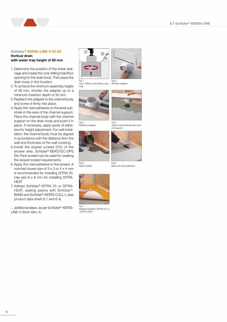
Schlüter®-KERDI-LINE-V 50 G2Vertical drainwith water trap height of 50 mm
1. Determine the position of the linear drai-nage and create the core drilling hole/floor opening for the drain body. Then place the drain body in this location.
2. To achieve the minimum assembly height of 48 mm, shorten the adapter up to a minimum insertion depth of 30 mm.
3. Reattach the adapter to the channel body and screw it firmly into place.
4. Apply thin-bed adhesive on the level sub-strate in the area of the channel support. Place the channel body with the channel support on the drain body and push it in place. If necessary, apply spots of adhe-sive for height adjustment. For wall instal-lation, the channel body must be aligned in accordance with the distance from the wall and thickness of the wall covering.
5. Install the sloped screed (2%) of the shower area. Schlüter®-BEKOTEC-DPS Dry Pack screed can be used for creating the sloped screed requirements.
6. Apply thin-bed adhesive to the screed. A notched trowel size of 3 x 3 or 4 x 4 mm is recommended for installing DITRA 25. Use size 6 x 6 mm for installing DITRA-HEAT
7. Adhere Schlüter®-DITRA 25 or DITRA-HEAT, sealing seams with Schlüter®-BAND and Schlüter®-KERDI-COLL-L (see product data sheet 6.1 and 6.4).
... additional steps, as per Schlüter®-KERDI-LINE-H (from item 4).
��
Fig 1.Core drilling hole/ceiling ope-ning
Fig 2.Shorten adapter
Fig 3.Reattach adapter
Fig 4.Attach channel body with chan-nel support
Fig 5.Apply screed
Fig 7.Adhere Schlüter®-DITRA-25 or -DITRA-HEAT
Fig 6.Apply thin-bed adhesive
8.7 Schlüter®-KERDI-LINE
9
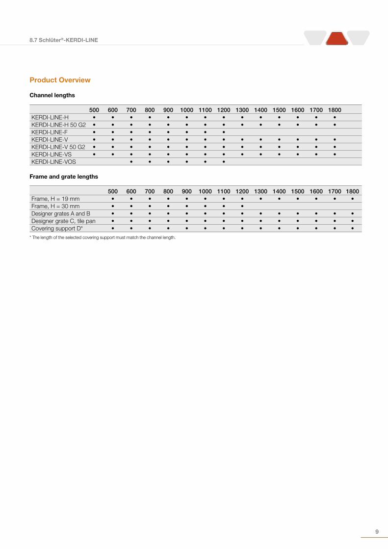
Product Overview
Channel lengths
Frame and grate lengths
500 600 700 800 900 1000 1100 1200 1300 1400 1500 1600 1700 1800 KERDI-LINE-H • • • • • • • • • • • • • •KERDI-LINE-H 50 G2 • • • • • • • • • • • • • •KERDI-LINE-F • • • • • • • • KERDI-LINE-V • • • • • • • • • • • • • •KERDI-LINE-V 50 G2 • • • • • • • • • • • • • •KERDI-LINE-VS • • • • • • • • • • • • • •KERDI-LINE-VOS • • • • • •
500 600 700 800 900 1000 1100 1200 1300 1400 1500 1600 1700 1800 Frame, H = 19 mm • • • • • • • • • • • • • •Frame, H = 30 mm • • • • • • • • Designer grates A and B • • • • • • • • • • • • • •Designer grate C, tile pan • • • • • • • • • • • • • •Covering support D* • • • • • • • • • • • • • •
* The length of the selected covering support must match the channel length.
8.7 Schlüter®-KERDI-LINE
10
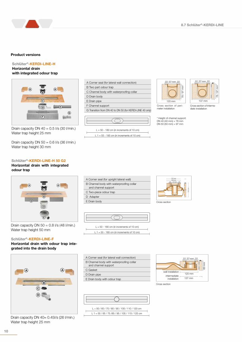
Schlüter®-KERDI-LINE-HHorizontal drain with integrated odour trap
Schlüter®-KERDI-LINE-H 50 G2Horizontal drain with integrated odour trap
A Corner seal (for lateral wall connection)
B Two part odour trap
C Channel body with waterproofing collar
D Drain body
E Drain pipe
F Channel support
G Transition from DN 40 to DN 50 (for KERDI-LINE 40 only)
A Corner seal (for upright lateral wall)
B Channel body with waterproofing collar and channel support
C Two-piece odour trap
D Adapter
E Drain body
= L
= L 1
L = 50 - 180 cm (in increments of 10 cm)
L 1 = 55 - 185 cm (in increments of 10 cm)
= L
= L 1
L = 50 - 180 cm (in increments of 10 cm)
L 1 = 55 - 185 cm (in increments of 10 cm)
F
G
D
C
E
BA A
D
E
B
C
A A
B
Drain capacity DN 40 = 0.5 l/s (30 l/min.)Water trap height 25 mm
Drain capacity DN 50 = 0.6 l/s (36 l/min.)Water trap height 30 mm
Drain capacity DN 50 = 0.8 l/s (48 l/min.)Water trap height 50 mm
120 mm
57 mm22 22
78 /
97
mm
*57 mm 2222
120
mm
137 mm120 mm
137 mm
57 mm
78 /
97
mm
*
22 22
Cross section of interme-diate installation
Cross section of peri-meter installation
Cross section
* Height of channel support:DN 40 (40 mm) = 78 mmDN 50 (50 mm) = 97 mm
Schlüter®-KERDI-LINE-FHorizontal drain with odour trap inte-grated into the drain body
D
C
B
A A
Drain capacity DN 40= 0.45l/s (26 l/min.) Water trap height 25 mm
A Corner seal (for lateral wall connection)
B Channel body with waterproofing collar and channel support
C Gasket
D Drain pipe
E Drain body with odour trap
= L
= L 1
L = 50 / 60 / 70 / 80 / 90 / 100 / 110 / 120 cm
L 1 = 55 / 65 / 75 /85 / 95 / 105 / 115 / 125 cm
57 mm
60 m
m
22 22
120 mmwall installation
intermediateinstallation 137 mm
Cross section
Product versions
8.7 Schlüter®-KERDI-LINE
11
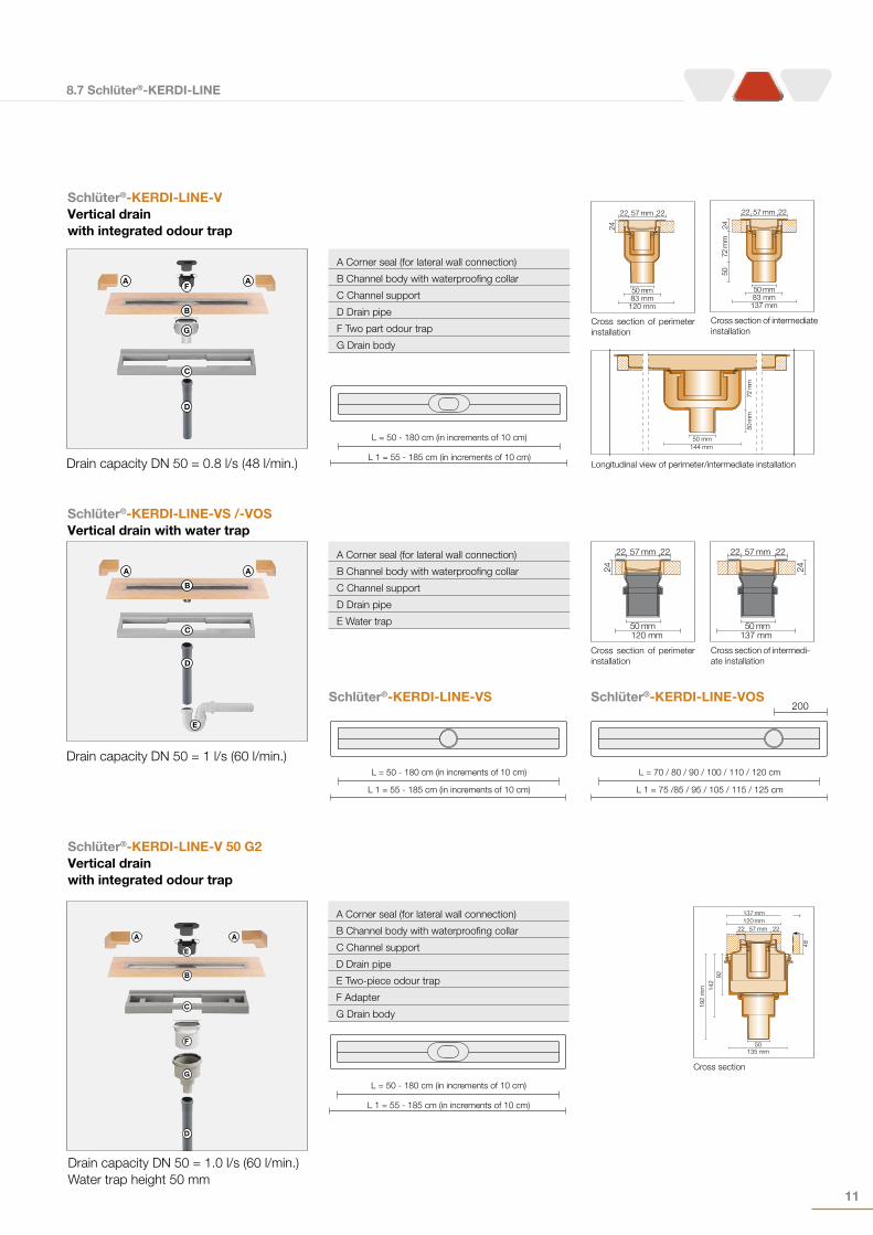
Schlüter®-KERDI-LINE-V 50 G2Vertical drain with integrated odour trap
A Corner seal (for lateral wall connection)
B Channel body with waterproofing collar
C Channel support
D Drain pipe
E Two-piece odour trap
F Adapter
G Drain body
= L
= L 1
L = 50 - 180 cm (in increments of 10 cm)
L 1 = 55 - 185 cm (in increments of 10 cm)
C
D
G
F
B
E
A A
Drain capacity DN 50 = 1.0 l/s (60 l/min.)Water trap height 50 mm
57 mm 2222
137 mm120 mm
50135 mm
48
9214
219
2 m
m
Cross section
Schlüter®-KERDI-LINE-VVertical drain with integrated odour trap
D
C
B
F
G
A A
Drain capacity DN 50 = 0.8 l/s (48 l/min.)
A Corner seal (for lateral wall connection)
B Channel body with waterproofing collar
C Channel support
D Drain pipe
F Two part odour trap
G Drain body
57 mm
24
83 mm
2222
50 mm
120 mm
57 mm
24
2222
83 mm50 mm
137 mm
50
72 m
m
= L
= L 1
L = 50 - 180 cm (in increments of 10 cm)
L 1 = 55 - 185 cm (in increments of 10 cm)
Cross section of intermediate installation
Cross section of peri meter installation
50 mm144 mm
50 m
m72
mm
Longitudinal view of perimeter/intermediate installation
Schlüter®-KERDI-LINE-VS /-VOSVertical drain with water trap
Schlüter®-KERDI-LINE-VS Schlüter®-KERDI-LINE-VOS
D
C
E
B
A A
Drain capacity DN 50 = 1 l/s (60 l/min.)
A Corner seal (for lateral wall connection)
B Channel body with waterproofing collar
C Channel support
D Drain pipe
E Water trap
= L
= L 1
L = 50 - 180 cm (in increments of 10 cm)
L 1 = 55 - 185 cm (in increments of 10 cm)
57 mm
24
120 mm
2222
50 mm
57 mm
24
137 mm
2222
50 mm
Cross section of intermedi-ate installation
Cross section of peri meter installation
= L
= L 1
200
L = 70 / 80 / 90 / 100 / 110 / 120 cm
L 1 = 75 /85 / 95 / 105 / 115 / 125 cm
8.7 Schlüter®-KERDI-LINE
Schlüter-Systems KG · Schmölestraße 7 · D-58640 Iserlohn · Tel.: +49 2371 971-261 · Fax: +49 2371 971-112 · www.schlueter-systems.com
Schlüter-Systems Ltd · Units 3-5 Bardon 22 Industrial Estate · Beveridge Lane · Coalville · Leicestershire · LE67 1TETel.: +44 1530 813396 · Fax: +44 1530 813376 · [email protected] · www.schluter.co.uk A
rt.-
No.
553
229
– 0
8/16
Issu
e –
Rep
rints
will
inva
lidat
e th
is is
sue.
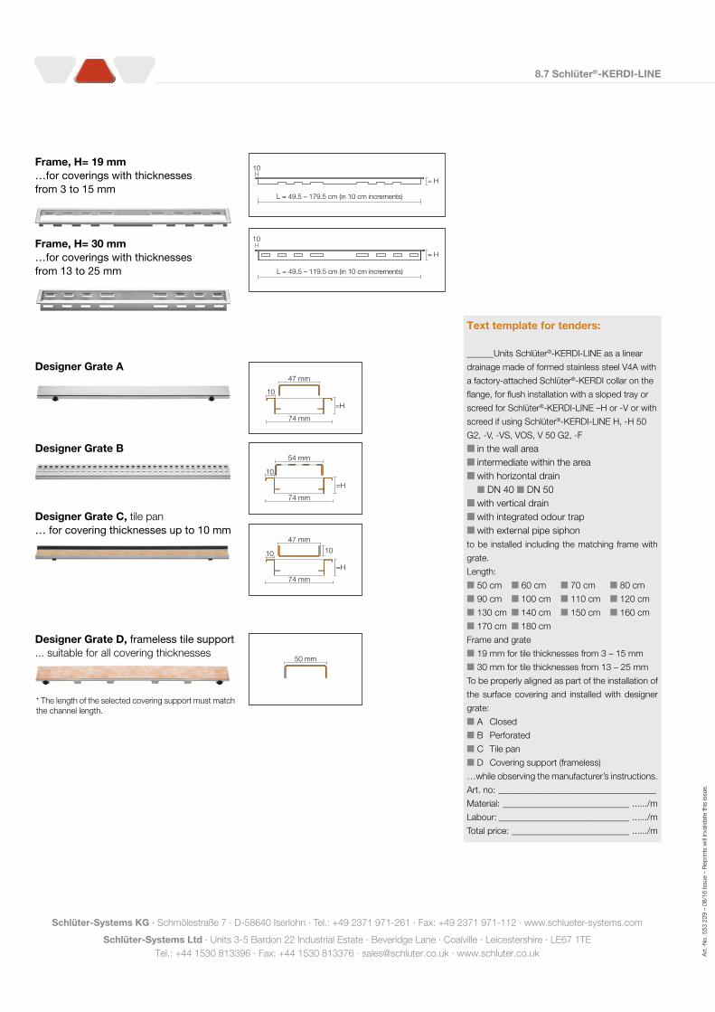
L = 49.5 – 179.5 cm (in 10 cm increments)
10
= H
L = 49.5 – 119.5 cm (in 10 cm increments)
10
= H
Designer Grate D, frameless tile support... suitable for all covering thicknesses
=H
10
74 mm
47 mm
54 mm
10
=H
74 mm
47 mm
10
=H
74 mm
10
50 mm
Frame, H= 19 mm…for coverings with thicknesses from 3 to 15 mm
Frame, H= 30 mm…for coverings with thicknesses from 13 to 25 mm
Designer Grate A
Designer Grate B
Designer Grate C, tile pan… for covering thicknesses up to 10 mm
* The length of the selected covering support must match the channel length.
Text template for tenders:
______Units Schlüter®-KERDI-LINE as a linear
drainage made of formed stainless steel V4A with
a factory-attached Schlüter®-KERDI collar on the
flange, for flush installation with a sloped tray or
screed for Schlüter®-KERDI-LINE –H or -V or with
screed if using Schlüter®-KERDI-LINE H, -H 50
G2, -V, -VS, VOS, V 50 G2, -F
in the wall area intermediate within the area with horizontal drain DN 40 DN 50 with vertical drain with integrated odour trap with external pipe siphon
to be installed including the matching frame with
grate.
Length:
50 cm 60 cm 70 cm 80 cm
90 cm 100 cm 110 cm 120 cm
130 cm 140 cm 150 cm 160 cm
170 cm 180 cm
Frame and grate
19 mm for tile thicknesses from 3 – 15 mm
30 mm for tile thicknesses from 13 – 25 mm
To be properly aligned as part of the installation of
the surface covering and installed with designer
grate:
A Closed
B Perforated
C Tile pan
D Covering support (frameless)
…while observing the manufacturer’s instructions.
Art. no: ___________________________________
Material: ____________________________ ....../m
Labour: _____________________________ ....../m
Total price: __________________________ ....../m