Embed Size (px)
Citation preview
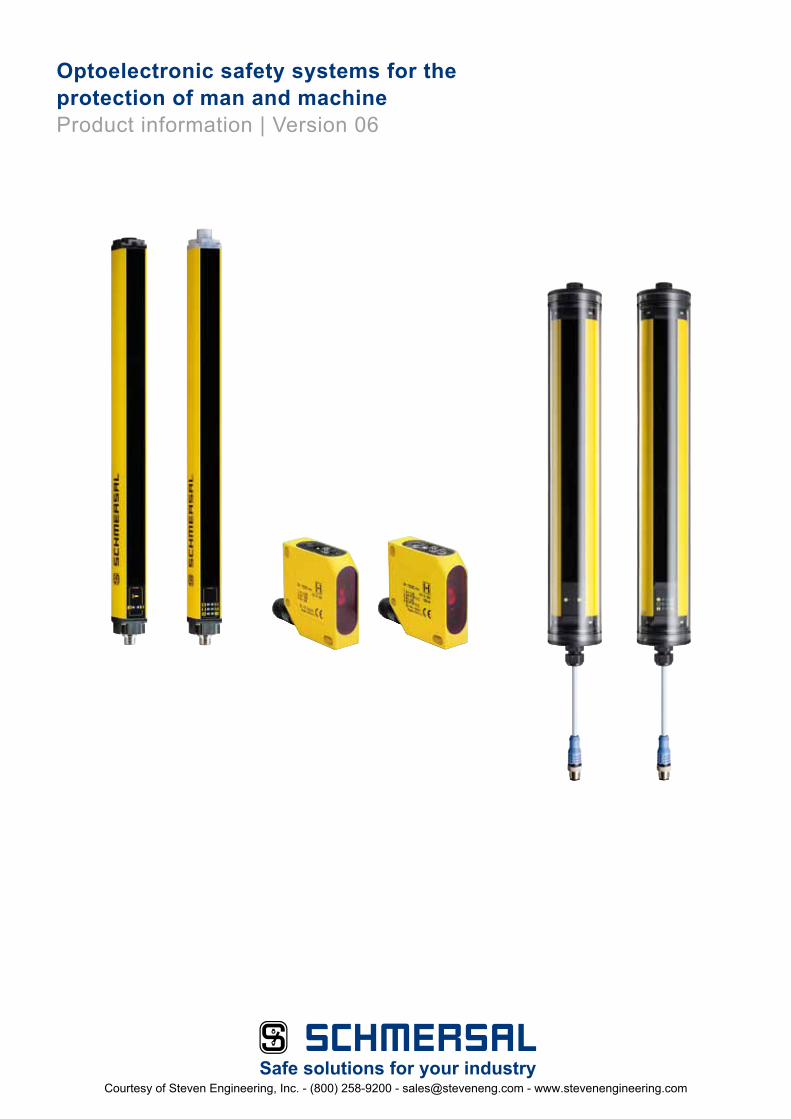
Optoelectronic safety systems for the protection of man and machineProduct information | Version 06
Safe solutions for your industryCourtesy of Steven Engineering, Inc. - (800) 258-9200 - [email protected] - www.stevenengineering.com

2Courtesy of Steven Engineering, Inc. - (800) 258-9200 - [email protected] - www.stevenengineering.com

3
Contents
Introduction
Optical safety sensors . . . . . . . . . . . . . . . . . . . . . . . . . . . . . . . . . . . . . . . . . . . . . . . . . . . . . . . . . . . . . . . . . . . . Page 4
Design and operating principle . . . . . . . . . . . . . . . . . . . . . . . . . . . . . . . . . . . . . . . . . . . . . . . . . . . . . . . . . . . . Page 6
Application of EN 999: Safety distances . . . . . . . . . . . . . . . . . . . . . . . . . . . . . . . . . . . . . . . . . . . . . . . . . . . . . . Page 8
Modes of operation and functions . . . . . . . . . . . . . . . . . . . . . . . . . . . . . . . . . . . . . . . . . . . . . . . . . . . . . . . . . . Page 10
Products
Safety light barriers . . . . . . . . . . . . . . . . . . . . . . . . . . . . . . . . . . . . . . . . . . . . . . . . . . . . . . . . . . . . . . . . . . . . . . Page 13
Safety light curtains and light grids . . . . . . . . . . . . . . . . . . . . . . . . . . . . . . . . . . . . . . . . . . . . . . . . . . . . . . . . . . Page 21
Safety monitoring modules . . . . . . . . . . . . . . . . . . . . . . . . . . . . . . . . . . . . . . . . . . . . . . . . . . . . . . . . . . . . . . . . Page 39
Appendix
Glossary . . . . . . . . . . . . . . . . . . . . . . . . . . . . . . . . . . . . . . . . . . . . . . . . . . . . . . . . . . . . . . . . . . . . . . . . . . . . . . . Page 12
Schmersal offers its customers a comprehensive range of products for optoelectronic safeguarding of hazardous areas, ranging from light barriers, light grids and light curtains with different functions (e .g . blanking, muting, cascading) . A large range of accessories, e .g . deflecting mirrors, mounting brackets etc . helps the user fitting and using those active optoelectronic protective devices (AOPD) in his specific application .
This brochure contains a brief introduction of the individual optoelectronic product families as well as the main accessories for the AOPD systems of the Schmersal Group .
The technical data of the individual devices are completed with wiring examples, e .g . in combination with Safety monitoring modules or for integration in the AS-i Safety at Work System . Appropriate components can be wired into a complete safety system .
Descriptions of technical correlations, details on external control units, installation or operating instructions or similar have been provided to the best of our knowledge . However, this does not mean that any warranted characteristics or other properties under liability law may be assumed which extend beyond the “General Terms of Delivery of Products and Services of the Electrical Industry” .
All the data mentioned in this catalog have been carefully checked . Subject to technical modifications and errors .
Courtesy of Steven Engineering, Inc. - (800) 258-9200 - [email protected] - www.stevenengineering.com

4
The field of automation is subject to a permanent and innovative change of products and applications . The focus is on increasing the produc-tivity and realizing a smooth-running production process with a minimum of human interventions on machinery and systems . The ideal, a fully automated and totally safe machine however will always remain a dream, though the robots used in production plants already are a big step towards this goal .Human intervention and knowledge will always be re-quired for the commissioning, monitoring and maintenance of modern industrial systems . Man however is not infallible and ignorance or lack of in-formation, thoughtlessness or negligence often leads to damages .
For these reasons European directives such as the Ma-chinery Directive 98/37/EC (2006/42/EG) and their corre-sponding standards were im-plemented at European level .These standards aim at de-tecting and constructively avoiding all possible risks and hazards during the planning and project phase of ma-chines and systems . Safety components must be used to minimize or eliminate the resi-dual risks .In this way, manufacturers and users are making equivalent efforts to set up an optimal process flow, which offers the highest possible protection to the operating staff . The chal-lenge for all manufacturers of safety components is to de-sign efficient and safe product solutions for mechanical engi-neers . Flaps and doors are the simplest means of access to the machine .These separating hardguar-ding safety solutions offer an efficient and effective protec-tion against hazardous mo-vements and products being ejected from the machine .When these safety guards are opened, the machine is brought to standstill (through the corresponding safety sensor transmitting the “stop” signal to the control), which interrupts and therefore slows down the production . In case
of continuous processes, which must not be interrup-ted, solenoid interlocks pro-tect man and the work piece against damages .Safety fences are not suitable for production processes requiring the material to be transported into the working area by means of conveyor belts, as it does not allow for an ergonomic and optimal work sequence .
A “virtual safety guard“ in the form of an active optoelec-tronic device (AOPD), e .g . a safety light curtain, is a perfect solution, offering both an op-timal protection of human life and uninterrupted production process .
Introduction – Optoelectronic safety sensors
EN 61
Courtesy of Steven Engineering, Inc. - (800) 258-9200 - [email protected] - www.stevenengineering.com

5
Typical applications:
• Power-driven machines• Power-driven presses in me-
talworking, plastics, leather, stone working and rubber processing industry
• Folding presses and cutters• Filter presses• Punching machines in lea-
ther, textile and plastics processing
• Robots stations and welding booths
• Printing and injection moul-ding machines
• Transportation systems• Pallet loaders and palletizers• Materials handling and sto-
rage technology• and so on
Depending on the application, the AOPD are used for point of operation, danger zone and perimeter guarding . The user can choose from a large range of different optoelectro-nic safety solutions e .g . light barriers, light grids and light curtains .
EN 61496
Courtesy of Steven Engineering, Inc. - (800) 258-9200 - [email protected] - www.stevenengineering.com

6
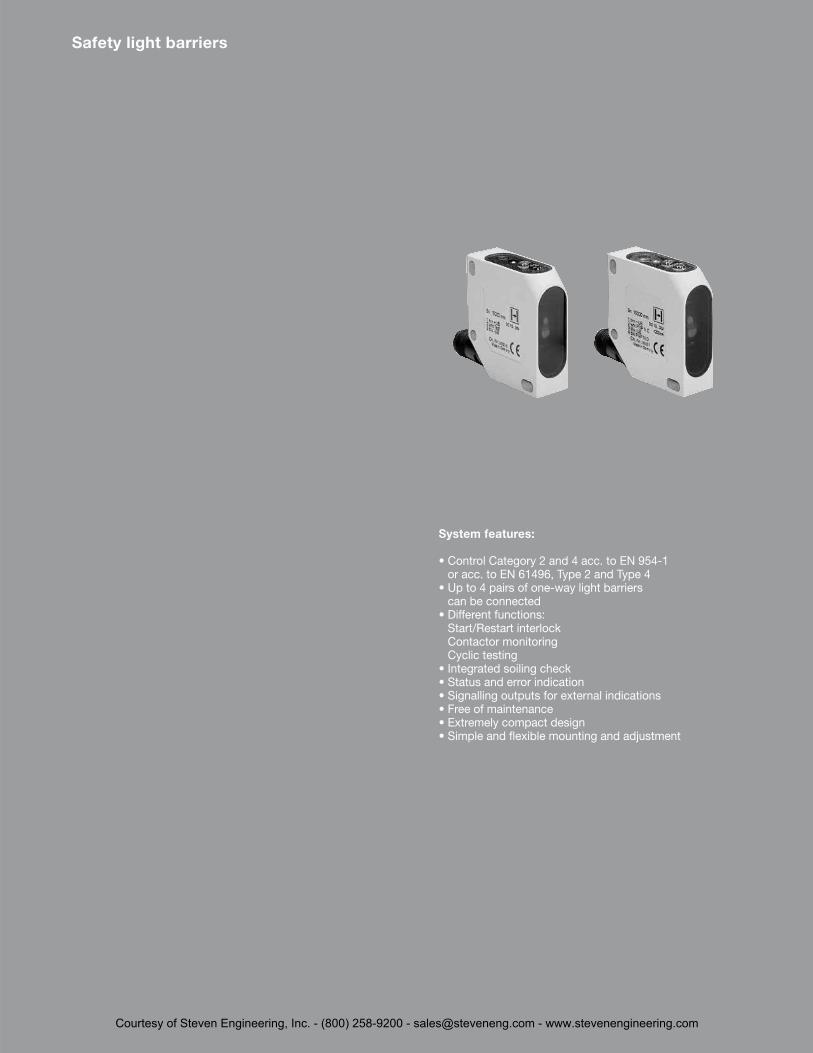
Safety light barriers
The safety light barrier sy-stems of the SLB range are active optoelectronic protec-tive devices (AOPD) fulfilling the Control Category 2 or 4 in accordance with EN 954-1 or EN 61496 . These systems are used as entry guards on hazardous zones, points of operation and entrances .They protect human life with-out restricting the production flow .Typical applications for safety light barriers are on robots, automatic-processing plants, transfer lines, rack storages and pallet loaders .The entire safety light barrier system includes a light emit-ter, a light receiver and a safe-ty monitoring module .This module monitors the signals of the emitter .If the light beam is interrupted, a signal is emitted to bring the dangerous movement of the machine to standstill . The safety monitoring module integrates functions such as start and restart inhibit as well as a contactor monitoring .The maintenance-free safety sensors of the system with protection class IP 67 offer an integrated soiling check .Because of their small size, safety light barriers can be fit-ted almost everywhere .
Safety light grids / light curtains
The safety light curtains and safety light grids of the SLC and SLG meet the require-ments of Control Category 2 or 4 to EN 954-1 and Type 2 or Type 4 to EN 61496 .They safeguard points of ope-ration and hazardous areas on different applications, e .g . presses, robot stations, injec-tion moulding machines, pallet machines, etc .In these active optoelectronic protective devices (AOPD), the emitter and receiver are fitted in two separate enclosures . An invisible infrared signal is sent from the emitter and mo-nitored by the receiver . If the light beam is interrupted by an object or a person, a stop signal is emitted to bring the machine to standstill .The protection field is defined by the height and width of the protection field . The protec-ted height is the range bet-ween the first and last infrared light beam of a light curtain . The protected height defines the physical size of the system to be used .The protected width or oper-ating range is the distance between the transmitter and receiver unit .
For an accurate detection of objects with different sizes in the hazardous area, the user can choose between light grids and light curtains with different resolutions . Here, the following rule applies: the smaller the distance between two adjacent light beams, the more accurate the detection sensitivity of the AOPD .For the detection of body parts, a distinction is made between finger, hand and body protection .EN 999 or DIN EN ISO 13857 sets the biometric data for finger protection to 14 mm, for hand detection to 30 mm, for leg detection up to 70 mm and for body detection to over 70 mm .Safety light grids with 2, 3 or 4 individual beams are generally used to detect the penetration of the entire human body .Safety light curtains are mul-tiple beam systems (> 5 indi-vidual beams) and can also detect smaller objects in case of intrusion into the protected field . The maintenance-free safety light curtains and light grids can be smoothly fitted using an M12 connector and are equipped with a diagno-stic interface and LED indica-tion for status messages .
Depending on the type of safety light curtain or light grid used, the components offer an integrated monitoring module with start/restart inhibit and external device monitoring . Additional functions such as blanking, muting and casca-ding of the light curtains are available as well .The SLC and SLG product se-ries therefore offer a maximum of flexibility for safeguarding different points of operation .
Design and operating principle
Optoelectronic
Protected width (operating range)
Light beam
Pro
tect
ed h
eig
ht
Courtesy of Steven Engineering, Inc. - (800) 258-9200 - [email protected] - www.stevenengineering.com

7
Important conditions for the use of optoelectronic safety devices:
In order to choose the appro-priate active optoelectronic protective device (AOPD) such as light barriers and light curtains/grids and to use them correctly, both the require-ments of the standards (EN 61496, EN 999, EN 294, C standards etc .) and product-specific features (detection sensitivity, range, etc .) must be taken into account . AOPD’s can be used, provided that:
• the dangerous movement can be stopped at all times and that it is ensured that the dangerous area can only be reached after the move-ment has come to standstill,
• the run-out time of the ma-chine and all safety compo-nents is known,
• no objects (work pieces, sparks, liquids, etc .) can be ejected,
• the AOPD meet the require-ments of Type 2 or Type 4 acc . to EN 61496,
• the dangerous area can only be reached by passing through the protected field of the AOPD,
• reaching over, under or through the protected field is impossible,
• the start or restart command devices are fitted in such a way that the entire ha-zardous area is completely visible from the outside and that it cannot be activated from within the hazardous area
• and the safety distance is calculated and construc-tively applied in accordance with EN 999 .
The effectiveness of the safety guard corresponds to the risk assessment, which was car-ried out during the planning and design phase, taking all important boundary conditi-ons, e .g . environment, machi-ne and function into account .
Optoelectronic safety systems
Courtesy of Steven Engineering, Inc. - (800) 258-9200 - [email protected] - www.stevenengineering.com

8
If the dangerous area of the machine is accessible from the top because of its parti-cular construction, the height H of the topmost beam of the light barrier must be at least 1800 mm above the base G of the machine .
Normal approach for light curtains: (Resolution: from 40 mm up to max. 70 mm)
The minimum safety distance S is calculated in the following way:
S = 1600 T + 850
The height of the topmost light beam must be at least 900 mm, the height of the lo-wermost light beam maximum 300 mm above the bottom (for the protection of children younger than 14: 200 mm)
Safety distances for light curtains
Between the interruption of a light beam and the standstill of the machine, a certain time expires . The safety light grid or light curtain must be sized and installed such that a stop would be signalled and the hazard ceased prior to a per-son or a body part accessing the hazard .The standard EN 999 provides the user with detailed informa-tion about the calculation of the minimum safety distances . These include the following important influencing factors:
• run-out time of the entire system, taking the different reaction times of the indivi-dual systems into account (e .g . machine, safety moni-toring module, AOPD etc .)
• capacity of the AOPD to detect body parts (fingers, hand and entire human body)
• set-up of the safety guard in normal condition (vertical fitting), parallel condition (horizontal fitting) or at an arbitrary angle in front of the safety guard and
• the speed at which the pro-
tection field is approached .
For the calculation of the mi-nimum safety distance S to the hazardous area, EN 999 presents the following general formula:
S = K x T + C
Where:S the safety distance to the
dangerous area (mm)
K the approach speed of the body or the body part (mm/s)
T the entire reaction time of the system(s) (including the machine’s run-out time, the reaction time of the safety guard and the safety monitoring mo-dule etc .)
C additional distance (mm) in front of the safety guard
Normal approach for light curtains: (Resolution: max. 40 mm)
The minimum safety distance S is calculated in the following way:
S = 2000 T + 8 (D-14)
(D = Resolution)
This formula applies to safety distances up to 500 mm .The minimum safety distance Smin may not be less than 100 mm .
If the calculation produces a distance larger than 500 mm for S, the calculation can be repeated with a lower ap-proach speed:
S = 1600 T + 8 (D-14)
In this case, Smin may not be less than 500 mm .
EN
999
Application
H
S
Safety distance
Light curtain Point of operation
Approach direction
Reference floor
Courtesy of Steven Engineering, Inc. - (800) 258-9200 - [email protected] - www.stevenengineering.com

9
Normal approach for light grids: (Resolution: > 70 mm)
The minimum safety distance S is calculated using the follo-wing formula:
S = 1600 T + 850
For safety guards with mul-tiple beams, height H (mm) above the reference floor of the individual beams must be applied in the following way:
When using light curtains or light grids, particular attention must be paid to the tampering possibilities of the safety guard and to the mechanical risks (e .g . crushing, shearing, cutting, ejection) .
Horizontal approach for light curtains/grids (Resolution: > 50 mm)
The minimum safety distance S is calculated using the follo-wing formula:
S = 1600 T + 1200 – 0.4 H
Here, Smin is 850 mm . The lowest authorised height H depends on the resolution D of the light curtain:
H = 15 (D-50)
For this type of safety guard, the maximum height H is 1000 mm .In the risk analysis, special attention must be paid to the prevention of unintentional un-detected access from under-neath the protection field .
Further calculation examples can be found in DIN EN 999 as well as in the mounting instructions of the SLC/SLG safety sensors .
300
1100
700
S S
H
Safety distance
Light curtain/grid
Light curtain/grid
Point of operation
Point of operation
Direction of approach
Direction of approach
Reference floor Reference floor
Number Height above the of beams reference floor
2 400, 9003 300, 700, 11004 300, 600, 900,1200
Courtesy of Steven Engineering, Inc. - (800) 258-9200 - [email protected] - www.stevenengineering.com

10
Master/Slave cascading
For the SLC/SLG…M/S prod-uct series, the master light curtain can be extended with another (slave) light curtain (cascading) . In this way, multiple protection fields can be generated . A protection field is created between the emitter and receiver and be-tween the slave components .
This device cascading pro-vides for a comfortable and efficient protection of contigu-ous protection fields against reaching over or through the protection field . The slave light curtains are connected to the master by means of an M12 connector .The master and slave light curtains are available in different sizes and resolutions and allow for almost any combination .
Muting
If goods or objects must be transported in or out of the hazardous area without stopping the machine, the safety light curtain must be automatically and temporarily suspended .
To this end, two or four mut-ing sensors are used to detect whether a person is approach-ing the hazardous area or a transport system enters or leaves the hazardous area . Suitable muting sensors are light barriers, proximity switches or position switches .The integrated safety-muting controller of the safety light curtain or light grid monitors and controls the muting process .
The safety outputs are not disabled . Any malfunction of the monitored signal source will cause the OSSD’s to be switched off .Depending on the application, different light curtains with integrated muting function are available .Detailed product information can be found in this brochure from page 33 .
Modes of operation and functions
Master
Slave
Courtesy of Steven Engineering, Inc. - (800) 258-9200 - [email protected] - www.stevenengineering.com
11
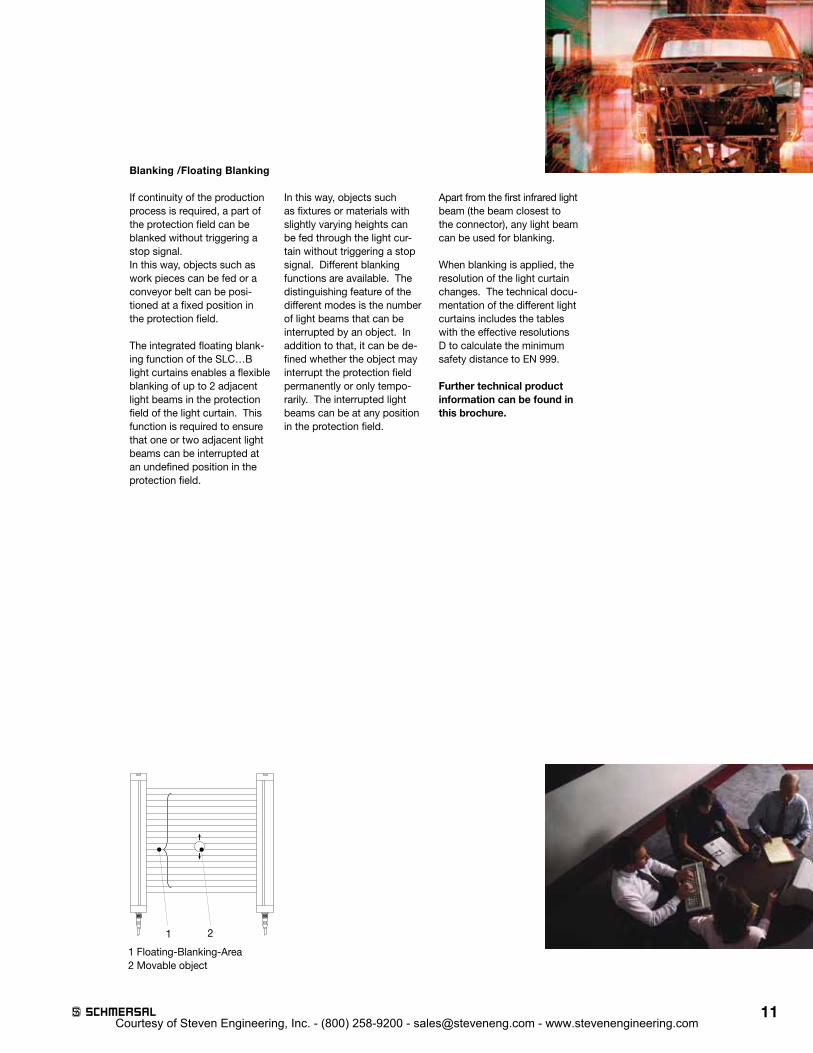
Blanking /Floating Blanking
If continuity of the production process is required, a part of the protection field can be blanked without triggering a stop signal .In this way, objects such as work pieces can be fed or a conveyor belt can be posi-tioned at a fixed position in the protection field .
The integrated floating blank-ing function of the SLC…B light curtains enables a flexible blanking of up to 2 adjacent light beams in the protection field of the light curtain . This function is required to ensure that one or two adjacent light beams can be interrupted at an undefined position in the protection field .
In this way, objects such as fixtures or materials with slightly varying heights can be fed through the light cur-tain without triggering a stop signal . Different blanking functions are available . The distinguishing feature of the different modes is the number of light beams that can be interrupted by an object . In addition to that, it can be de-fined whether the object may interrupt the protection field permanently or only tempo-rarily . The interrupted light beams can be at any position in the protection field .
Apart from the first infrared light beam (the beam closest to the connector), any light beam can be used for blanking .
When blanking is applied, the resolution of the light curtain changes . The technical docu-mentation of the different light curtains includes the tables with the effective resolutions D to calculate the minimum safety distance to EN 999 .
Further technical product information can be found in this brochure.
1 2
1 Floating-Blanking-Area2 Movable object
Courtesy of Steven Engineering, Inc. - (800) 258-9200 - [email protected] - www.stevenengineering.com

12
Definitions and terms:
Start interlock:A device preventing the au-tomatic release and therefore the automatic machine start when the power supply of the AOPD is switched on or inter-rupted and switched on again .
AOPD:The abbreviation of Active Op-toelectronic Protective Device .
Resolution:The resolution or minimum object sensitivity represents the minimum size of an object that is detected in each part of the protection field .
Optoelectronic safety devices:The here described are opto electronic safety guards (AOPD), e .g . safety light bar-riers, safety light curtains, safety light grids and their corresponding safety relay modules .
Type 2 acc. to EN 61496-1:The Type 2 AOPD is a pro-tective device, whose safety function is checked by means of regular tests . These de-vices must meet the require-ments of Control Category 2 acc . to EN 954-1 .
Type 4 acc. to EN 61496-1:The Type 4 AOPD is a pro-tective device, whose safety function is not affected by a failure or error in the system . These devices must meet the requirements of Control Category 4 acc . to EN 954-1 .
Blanking:In this configurable operation mode a safety light curtain blanks out a precisely defined area in the protection field . The operation mode . “Blank-ing“ allows objects to be present in the sending area with out deactivating the light curtain safety outputs . “Fixed Blanking” is when a fixed set of adjacent light beams are rendered inactive for the pur-pose of entering an object and pans into the protective area . “Floating Blanking“ is when a set member (one or more) of adjacent beams is allowed
to ignore the presence of an object and not deactivating the OSSDs of the light curtain .
Muting:Muting is a temporary auto-matic suspension of a safe-guarding function by safety-related parts of the control system during otherwise safe conditions in the operation of a machine . The safeguarding function is realized through 2 or 4 muting sensors, which can distinguish between persons and objects . The suspension condition is signalled by means of a muting signal lamp .
OSSD:Output Signal Switching Device of the AOPD (to EN 61496)
Protection field:The protection zone is an invisible, two-dimensional light curtain consisting of infrared light beams, installed between the emitter and receiver unit .Depending on the chosen re - solution (detection sensitivity) objects of a specific size intruding this light curtain will be detected .
Operating Range: The operating range is the maximum distance that may exit between the light curtain´s ermitter and its receiver .
Protected height:The protected height is a vertical area between the first and the last infrared light beam of an optoelectronic safety guard . (not the total housing length)The beginning and the end of this area is marked with symbols on the SLC/SLG’s enclosure .
Restart interlock:A device preventing the auto-matic restart of the machine, when the protection field is interrupted during a danger-ous machine cycle or when the operating mode of the machine is set or changed .
Glossary
Courtesy of Steven Engineering, Inc. - (800) 258-9200 - [email protected] - www.stevenengineering.com
13
System features:
• Control Category 2 and 4 acc . to EN 954-1 or acc . to EN 61496, Type 2 and Type 4
• Up to 4 pairs of one-way light barriers can be connected
• Different functions: Start/Restart interlock Contactor monitoring Cyclic testing
• Integrated soiling check• Status and error indication• Signalling outputs for external indications• Free of maintenance• Extremely compact design• Simple and flexible mounting and adjustment
Safety light barriers
Courtesy of Steven Engineering, Inc. - (800) 258-9200 - [email protected] - www.stevenengineering.com
14
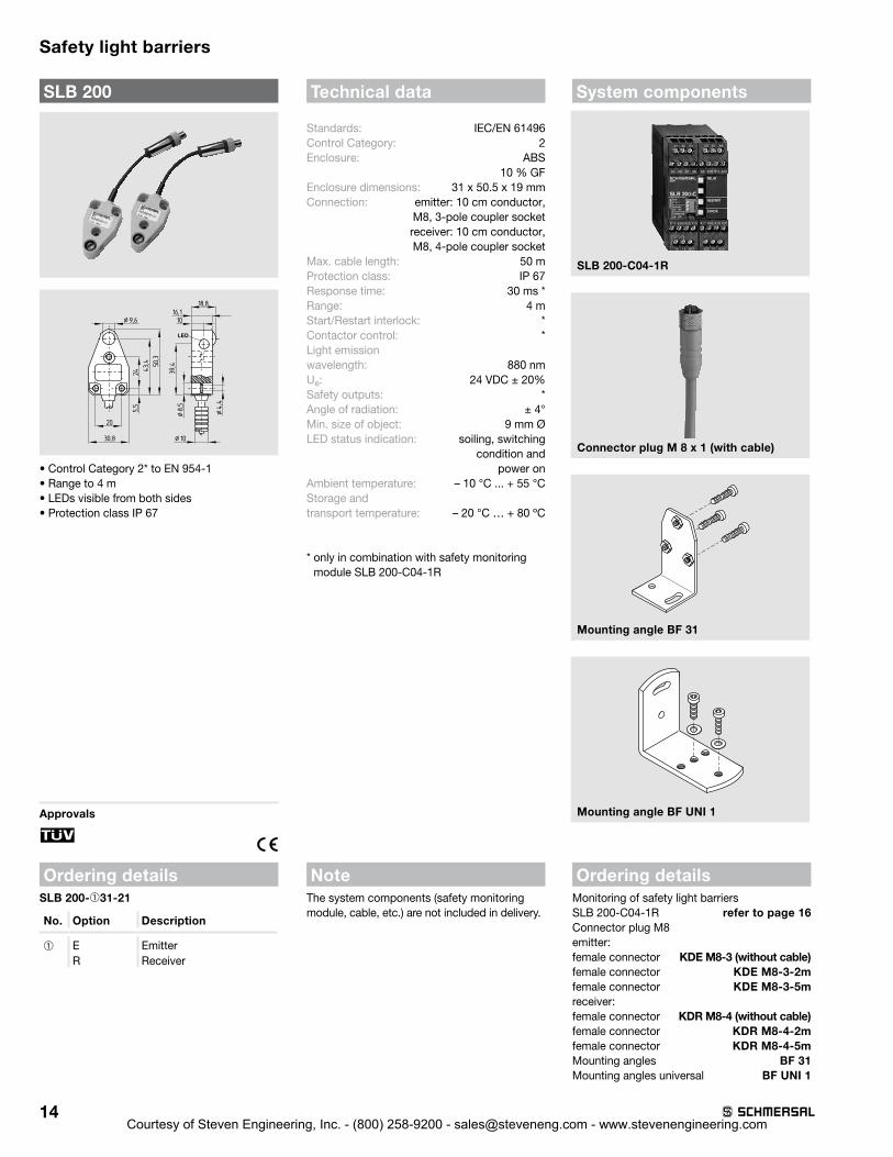
Safety light barriers
SLB 200
¤ 9,6
18,8
30,8
39,450,3
43,4
245,5
20
16,110
¤8,5
¤4,4
¤ 10
• Control Category 2* to EN 954-1 • Range to 4 m• LEDs visible from both sides• Protection class IP 67
Approvals
F
Ordering detailsSLB 200-➀31-21
No. Option Description
➀ E EmitterR Receiver
Technical data
Standards: IEC/EN 61496Control Category: 2 Enclosure: ABS
10 % GFEnclosure dimensions: 31 x 50 .5 x 19 mmConnection: emitter: 10 cm conductor,
M8, 3-pole coupler socket receiver: 10 cm conductor, M8, 4-pole coupler socket
Max . cable length: 50 mProtection class: IP 67Response time: 30 ms *Range: 4 mStart/Restart interlock: *Contactor control: *Light emission wavelength: 880 nmUe: 24 VDC ± 20%Safety outputs: *Angle of radiation: ± 4°Min . size of object: 9 mm ØLED status indication: soiling, switching
condition and power on
Ambient temperature: – 10 °C . . . + 55 °CStorage and transport temperature: – 20 °C … + 80 ºC
* only in combination with safety monitoring module SLB 200-C04-1R
NoteThe system components (safety monitoring module, cable, etc .) are not included in delivery .
System components
SLB 200-C04-1R
Connector plug M 8 x 1 (with cable)
Mounting angle BF 31
Mounting angle BF UNI 1
Ordering detailsMonitoring of safety light barriers SLB 200-C04-1R refer to page 16Connector plug M8emitter: female connector KDE M8-3 (without cable)female connector KDE M8-3-2mfemale connector KDE M8-3-5mreceiver:female connector KDR M8-4 (without cable)female connector KDR M8-4-2mfemale connector KDR M8-4-5mMounting angles BF 31 Mounting angles universal BF UNI 1
Courtesy of Steven Engineering, Inc. - (800) 258-9200 - [email protected] - www.stevenengineering.com

15
Safety light barriers
SLB 400
46 4416
4
4
17
4,3
4,3
13,5
63,5
4440
50
M 12x1
• Control Category 4* to EN 954-1 • Range to 15 m• Connecting plug can be rotated• LED switching conditions display• Protection class IP 67
Approvals
H
Ordering detailsSLB 400-➀50-21P
No. Option Description
➀ E EmitterR Receiver
Technical data
Standards: IEC/EN 61496Control Category: 4*Enclosure: ABSEnclosure dimensions: 50 x 50 x 17 mmConnection: Connector
connector plug M12, 4-polesocket, can be rotated
Max . cable length: 100 mProtection class: IP 67 Response time: 25 ms*Range: 15 mStart/Restart interlock: *Contactor control: *Light emission wavelength: 880 nmUe: 24 VDC ± 20%Safety outputs: *Angle of radiation: ± 2°Min . size of object: 13 mm ØLED status indication: soiling, switching
condition and power on
Ambient temperature: 0 °C . . . + 60 °CStorage and transport temperature: – 20 °C … + 80 ºC
* only in combination with safety monitoring module SLB 400-C10-1R
NoteThe system components (safety monitoring module, cable, etc .) are not included in delivery .
System components
SLB 400-C10-1R
Connector plug M 12 x 1 (with cable)
Mounting angle BF 50
Mounting angle BF UNI 1
Ordering detailsMonitoring of safety light barriers SLB 400-C10-1R refer to page 18Connector plug M12emitter/receiver: KD M12-4 (without cable) KD M12-4-2m KD M12-4-5mMounting angles BF 50 Mounting angles universal BF UNI 1
Courtesy of Steven Engineering, Inc. - (800) 258-9200 - [email protected] - www.stevenengineering.com

16
Safety light barriers
SLB 200-C
• Control Category 2 to EN 954-1, AOPD-T
• Up to two pairs of light barrier devices can be connected
• 1 enabling path• 1 signalling output• Operating voltage 24 VDC• Test input• LED display of switching conditions• Response time ≤ 30 ms• Start/Restart interlock can be
switched active or inactive• Contactor monitoring can be
switched active or inactive• Additional cyclic testing• Co-ordinated for use with
SLB 200 R/E safety light barriers
Approvals
F
Ordering detailsSLB 200-C04-1R
Technical data
Standards: IEC/EN 61496-1/-2, EN 954-1Control category: 2Start-up test: yesStart conditions: Test button, start-reset button, on/off codingFeedback circuit: yesEnclosure: polycarbonateMounting: snaps onto standard DIN rail to EN 50022Connection: screw terminalsCable section: max . 4 mm2 (incl . conductor ferrules)Protection class: IP 20Ue: 24 VDC ± 20%Ie: 180 mAInputs: test input: command device: NC contact
release start/restart interlock (start/reset): enable via command device (NO contact), contactor monitoring (NC contacts)
Monitored inputs max . 2 pairs of light barriersInput resistance: –Max . cable length: –Test and feedback: potential-free contactOutputs: 1 enabling pathEnabling contacts: 1 enabling pathUtilisation category: AC-15, DC-13Ie/Ue: 2 A / 250 VAC, 2 A / 24 VDCContact load capacity: max . 250 VAC, max . 2 A (cos j = 1)Switching voltage: max . 250 VACLoad current: 8 AMax . fuse rating: 4 A gG D-fuseSignalling output: 1 transistor outputSwitch-on conditions: test duration: ≤ 150 ms (without relay control)
≤ 450 ms (with relay control)Switch-off time: response time (complete sy .): ≤ 30 msIndications: red LED for light barrier interrupted
green LED for light barrier free soiling: flashing red/green
Function display: 4 LEDsEMC rating: conforming to EMC DirectiveMax . switching frequency: 10 HzOvervoltage category: II to DIN VDE 0110Degree of pollution: 3 to DIN VDE 0110Resistance to vibration: 10 . . . 55 Hz / amplitude 0 .35 mmResistance to shock: 10 g / 16 msAmbient temperature: 0 °C … + 50 ºCStorage and transport temperature: – 20 °C … + 80 ºCDimensions: 45 x 84 x 118 mmNote: Inductive loads (e .g . contactors, relays, etc .) are
to be suppressed by means of a suitable circuit .
Courtesy of Steven Engineering, Inc. - (800) 258-9200 - [email protected] - www.stevenengineering.com

17
Safety light barriers
Note
• For protection in Control Category 2 to EN 954-1
• Monitoring two pairs of light barrier devices and the power contactor using the SLB 200-C safety monitoring module
• Test push button IThe test push button is connected to X13 and X14 in order to carry out a check of the light barrier monitoring function . The terminals X15 and X16 must be bridged .
• The wiring diagram is shown for the de-energised condition .
• Contactor check To monitor an external contactor, the feed-back circuit is connected to X17 and X18 . The terminals X19 and X20 must be bridged .
• Start push button HThe start push button can be used to start the monitoring of the light barriers for a new start or after an interruption . The terminals X3 and X4 must be bridged .
• It is also possible to connect only one pair of light barrier devices .
NoteIn order to set for the desired mode of operation and number of light barriers con-nected, remove the front cover of the safety monitoring module . As supplied all switches are in Position 1 .
Wiring diagram
X21
L1
A1 X2
SLB-R
1 1 2 2
SLB-RSLB-E SLB-E
K1
X1 X6 X7 X8
X13 X14 X15 X16 X17 X18 X19 X20A2
3
X3 X4 X5 X10X9
NM
X11 X12 13
X22 Y1 X23 14
BN BN BN BNWH
BK WH
BK
+24 VDC
0 V
SLB 200-C
K3
K4
max.
Note The required functions can be selected by means of the internal DIP switches .
DIP switch 1 DIP switch 2 DIP switch 3
Position 1 With contactor check With start/restart interlock Connection of two light barriers
Position 2 Without contactor check Without start/restart interlock Connection of one light barrier
Courtesy of Steven Engineering, Inc. - (800) 258-9200 - [email protected] - www.stevenengineering.com

18
Safety light barriers
SLB 400-C
• Control Category 4 to EN 954-1, AOPD-S• Cross-wire monitoring• ISD Integral System Diagnostics• Operating voltage 24 VDC• Feedback circuit to monitor
external contactors• Two short-circuit proof additional
transistor outputs• Response time ≤ 30 ms• Start/Restart interlock can be
switched active or inactive• Contactor monitoring can be
switched active or inactive• Can be coded• Up to 4 light barrier pairs SLB 400
can be connected
Approvals
H
Ordering detailsSLB 400-C10-1R
Technical data
Standards: IEC/EN 61496-1/-2, EN 954-1Control category: 4Start-up test: yesStart conditions: Start-reset button, on/off codingFeedback circuit: yesEnclosure: glass-fiber reinforced thermoplasticMounting: snaps onto standard DIN rail to EN 50022Connection: screw terminalsCable section: max . 4 mm2 (incl . conductor ferrules)Protection class: terminals IP 20, enclosure IP 40Ue: 24 VDC ± 15%Ie: 0 .3 A without additional transistor outputsInputs: S1, S2Monitored inputs max . 4 pairs of light barriersInput resistance: approx . 2 kΩ to groundInput signal „1“: 10 . . . 30 VDCInput signal „0“: 0 . . . 2 VDCMax . cable length: 100 m of 0 .75 mm2 conductorOutputs: 2 enabling pathsEnabling contacts: 2 enabling pathsUtilisation category: AC-15, DC-13Ie/Ue: 2 A / 250 VAC, 2 A / 24 VDCContact load capacity: max . 250 VAC, max . 2 A (cos j = 1)Switching voltage: max . 250 VACLoad current: max . 2 ASwitching capacity: max . 500 VAMax . fuse rating: 2 A gG D-fuseAdditional outputs: additional transistor outputs Y1, Y2, Ue – 4 V,
100 mA total, short-circuit proof, p-typeSignalling output: 2 transistor outputs, Y1 + Y2 = max . 100 mA,
p-type, short-circuit proofSwitch-on time: –Response time: ≤ 25 msMonitoring for synchronism of muting sensors: –Indications: ISDFunction display: 9 LEDs (ISD*)EMC rating: conforming to EMC DirectiveMax . switching frequency: 10 HzOvervoltage category: II to DIN VDE 0110Degree of pollution: 3 to DIN VDE 0110Resistance to vibration: 10 . . . 55 Hz / amplitude 0 .35 mm, ± 15 %Resistance to shock: 30 g / 11 msAmbient temperature: 0 °C … + 55 ºCStorage and transport temperature: – 25 °C … + 70 ºCDimensions: 99 .7 x 75 x 110 mmNote: Inductive loads (e .g . contactors, relays, etc .) are
to be suppressed by means of a suitable circuit .
Courtesy of Steven Engineering, Inc. - (800) 258-9200 - [email protected] - www.stevenengineering.com

19
Safety light barriers
Note
• For protection in Control Category 4 to EN 954-1
• Monitoring up to four pairs of light barrier devices and the power contactors using the SLB 400-C safety monitoring module
• The wiring diagram is shown for the de-energised condition .
• Connection of two pairs of safety light barrier devices When two pairs of safety light barriers are connected, the terminals X9-X10 and X11-X12 must be bridged .
• Restart push button JThe restart function can be selected by means of the DIP switches . When a start push button is connected to X5 and X6, it must be operated for min . 250 ms and max . 5 s after an interruption of the safety light barriers .
ISDThe following faults are registered by the safety monitoring modules and indicated by ISD• Short-circuit on the connecting leads• Interruption of the connecting leads• Failure of the safety relay to pull-in
or drop-out• Fault on the input circuits or the relay control
circuits of the safety monitoring module• Mutual influence between the connected
pairs of light barrier device and others on neighbouring systems
Wiring diagram
L1
K4
K5
3
+24 VDC
0 V 0 V
NM
X2X1A1
1 2 3 4
1 2 3 4 1 2 3 4 1 2 3 4 1 2 3 4
1 2 3 4 1 2 3 4 1 2 3 4
X3 X4 X7X5 X6 X8 13 23 33 41
A2
0V
SLB-E
SLB-E SLB-E
SLB-R
SLB-R SLB-R
SLB-RSLB-E
T3 Q3 T4 Q4 PM INDIC.
U OUT
U OUT
B
B
Y1 Y2 -
-
+
+
X9 X10 X11 X12 X13 X14 14 24 34 42
24V T0 T2Q1 Q2 RESTART CONT.M
Made in Germany
RESTART RELAY
R
NoteThe ISD tables (Intergral System Diagnostics) for analysis of the fault indications and their causes are shown in the manual .
Courtesy of Steven Engineering, Inc. - (800) 258-9200 - [email protected] - www.stevenengineering.com

20
Safety light barriers accessories SLB 200 and SLB 400
System components
Mirror SLB 200/400 SMA 80
Mounting angle BF SMA 80-1
Mounting angle BF SMA 80-2
T-slot nut NST 20-8
Ordering detailsMirror SMA 80Mounting angles for mirror BF SMA 80-1
BF SMA 80-2T-slot nut NST 20-8
System components
Mounting post ST 1250
Floor-stand base STB 1
Ordering detailsMounting post ST 1250 Floor-stand base STB 1
Courtesy of Steven Engineering, Inc. - (800) 258-9200 - [email protected] - www.stevenengineering.com
21
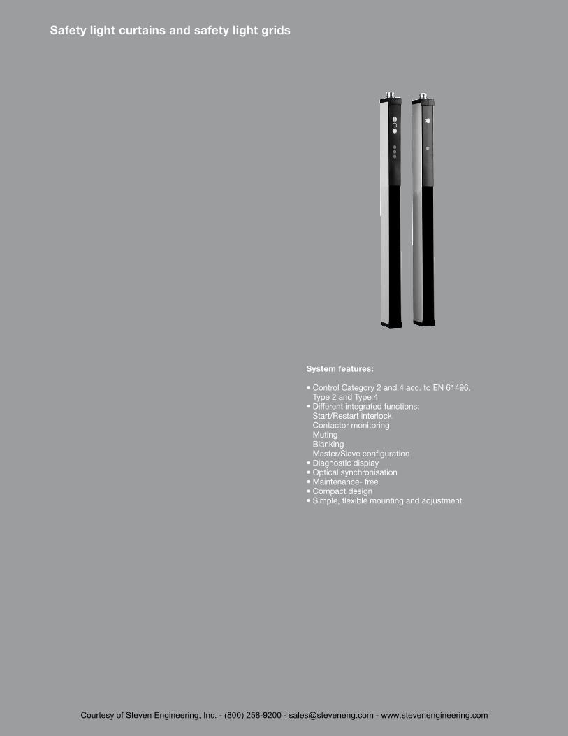
*
System features:
• Control Category 2 and 4 acc . to EN 61496, Type 2 and Type 4
• Different integrated functions: Start/Restart interlock Contactor monitoring Muting Blanking Master/Slave configuration
• Diagnostic display• Optical synchronisation• Maintenance- free• Compact design• Simple, flexible mounting and adjustment
Safety light curtains and safety light grids
Courtesy of Steven Engineering, Inc. - (800) 258-9200 - [email protected] - www.stevenengineering.com
22
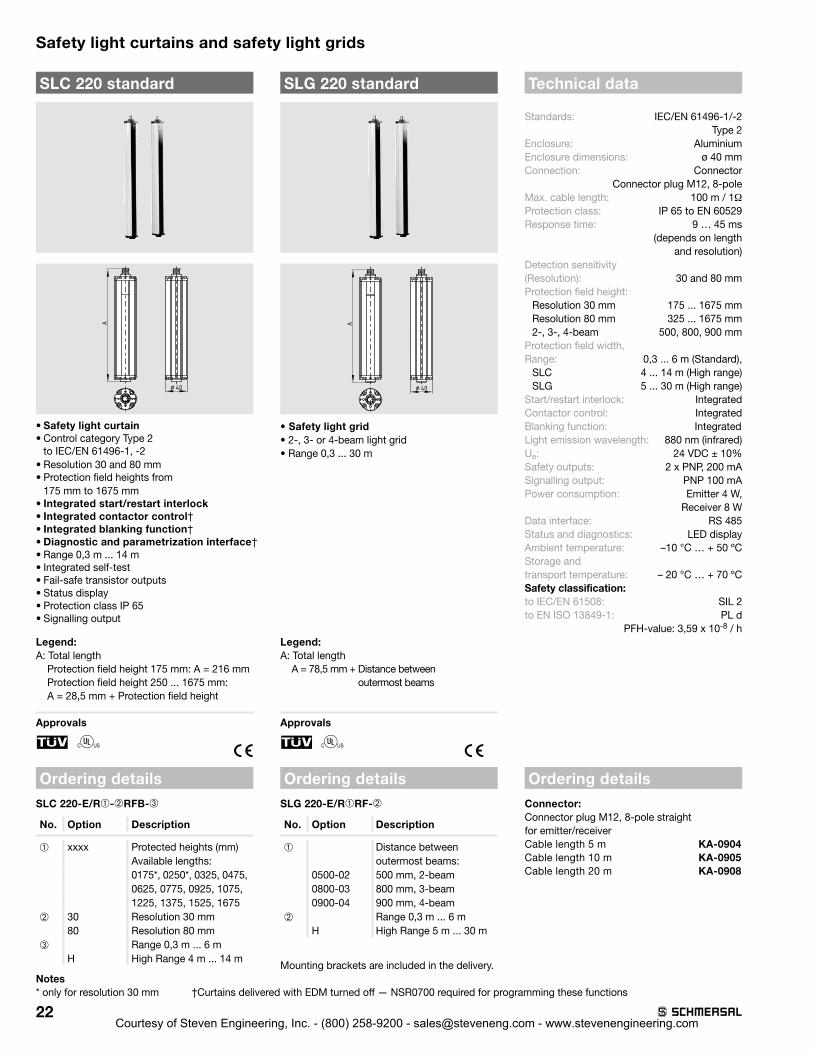
Safety light curtains and safety light grids
SLC 220 standardA
¤ 40
• Safety light curtain• Control category Type 2
to IEC/EN 61496-1, -2• Resolution 30 and 80 mm• Protection field heights from
175 mm to 1675 mm• Integrated start/restart interlock• Integrated contactor control†• Integrated blanking function†• Diagnostic and parametrization interface†• Range 0,3 m . . . 14 m• Integrated self-test• Fail-safe transistor outputs • Status display• Protection class IP 65• Signalling output
Legend:A: Total length
Protection field height 175 mm: A = 216 mm Protection field height 250 . . . 1675 mm: A = 28,5 mm + Protection field height
Approvals
F
Ordering detailsSLC 220-E/R➀-➁RFB-➂
No. Option Description
➀ xxxx Protected heights (mm)Available lengths:0175*, 0250*, 0325, 0475,0625, 0775, 0925, 1075, 1225, 1375, 1525, 1675
➁ 30 Resolution 30 mm80 Resolution 80 mm
➂ Range 0,3 m . . . 6 mH High Range 4 m . . . 14 m
Notes* only for resolution 30 mm
Technical data
Standards: IEC/EN 61496-1/-2 Type 2Enclosure: AluminiumEnclosure dimensions: ø 40 mmConnection: Connector
Connector plug M12, 8-poleMax . cable length: 100 m / 1ΩProtection class: IP 65 to EN 60529Response time: 9 … 45 ms
(depends on length and resolution)
Detection sensitivity (Resolution): 30 and 80 mmProtection field height:
Resolution 30 mm 175 . . . 1675 mmResolution 80 mm 325 . . . 1675 mm2-, 3-, 4-beam 500, 800, 900 mm
Protection field width, Range: 0,3 . . . 6 m (Standard),
SLC 4 . . . 14 m (High range)SLG 5 . . . 30 m (High range)
Start/restart interlock: IntegratedContactor control: IntegratedBlanking function: IntegratedLight emission wavelength: 880 nm (infrared)Ue: 24 VDC ± 10%Safety outputs: 2 x PNP, 200 mASignalling output: PNP 100 mAPower consumption: Emitter 4 W,
Receiver 8 WData interface: RS 485Status and diagnostics: LED displayAmbient temperature: –10 °C … + 50 ºCStorage and transport temperature: – 20 °C … + 70 ºCSafety classification: to IEC/EN 61508: SIL 2to EN ISO 13849-1: PL d
PFH-value: 3,59 x 10⁻⁸ / h
Ordering detailsConnector:Connector plug M12, 8-pole straightfor emitter/receiver Cable length 5 m KA-0904 Cable length 10 m KA-0905 Cable length 20 m KA-0908
SLG 220 standard
A
¤ 40
• Safety light grid• 2-, 3- or 4-beam light grid• Range 0,3 . . . 30 m
Legend:A: Total length
A = 78,5 mm + Distance between outermost beams
Approvals
F
Ordering detailsSLG 220-E/R➀RF-➁
No. Option Description
➀ Distance between outermost beams:
0500-02 500 mm, 2-beam0800-03 800 mm, 3-beam0900-04 900 mm, 4-beam
➁ Range 0,3 m . . . 6 mH High Range 5 m . . . 30 m
Mounting brackets are included in the delivery .
†Curtains delivered with EDM turned off — NSR0700 required for programming these functions
Courtesy of Steven Engineering, Inc. - (800) 258-9200 - [email protected] - www.stevenengineering.com

23
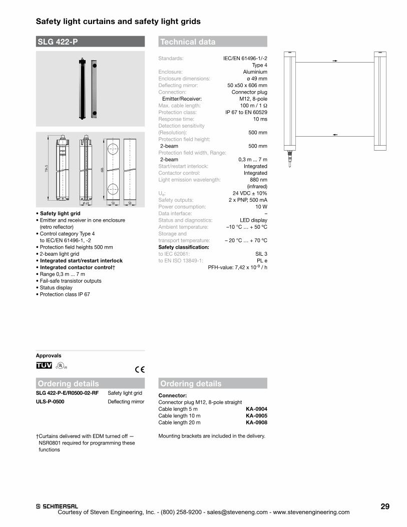
SLG 220-P734,5
¤ 49 50 50
606
Technische Daten
• Safety light grid• Emitter and receiver in one enclosure
(retro reflector)• Control category Type 2
to IEC/EN 61496-1, -2• Protection field heights 500 mm• 2-beam light grid • Integrated start/restart interlock• Integrated contactor control†• Range 0,3 m . . . 6 m• Fail-safe transistor outputs • Status display• Protection class IP 65
Approvals
F
Ordering detailsSLG 220-P-E/R0500-02RF Safety light grid
ULS-P-0500 Deflecting mirror
Ordering detailsConnector:Connector plug M12, 8-pole straightCable length 5 m KA-0904Cable length 10 m KA-0905Cable length 20 m KA-0908
Mounting brackets are included in the delivery .
Standards: IEC/EN 61496-1/-2 Type 2Enclosure: AluminiumEnclosure dimensions: ø 40 mmDeflecting mirror: 50 x50 x 606 mmConnection: Connector
Connector plug M12, 8-pole
Max . cable length: 100 m / 1 ΩProtection class: IP 65 to EN 60529Response time: 12 ms Detection sensitivity (Resolution): 500 mmProtection field height: 2-beam 500 mm
Protection field width, Range: 2-beam 0,3 m . . . 7 m
Start/restart interlock: IntegratedContactor control: IntegratedLight emission wavelength: 880 nm
(infrared)Ue: 24 VDC ± 10%Safety outputs: 2 x PNP, 200 mASignalling output: PNP 100 mAPower consumption: 10 WData interface: –Status and diagnostics: LED displayAmbient temperature: –10 °C … + 50 ºCStorage and transport temperature: – 20 °C … + 70 ºCSafety classification: to IEC/EN 61508: SIL 2to EN ISO 13849-1: PL d
PFH-value: 3,59 x 10⁻⁸ / h
Safety light curtains and safety light grids
† Curtains delivered with EDM turned off — NSR0700 required for programming these functions
Courtesy of Steven Engineering, Inc. - (800) 258-9200 - [email protected] - www.stevenengineering.com

24
Safety light curtains and safety light grids
SLC 220 Master / Slave
A
¤ 40
• Safety light curtain• Control category Type 2 to IEC/EN 61496-1, -2• Resolution 30 and 80 mm• Protection field height:
Master from 175 mm to 1675 mmSlave from 325 mm to 775 mm
• Integrated start/restart interlock• Integrated contactor control†• Diagnostic and parametrization interface†• Cascading of Master and Slave devices • Range 0,3 m . . . 6 m• Fail-safe transistor outputs • Status display• Protection class IP 65• Signalling output• Integrated self-test
Legend:A: Total length
Protection field height 175 mm: A = 216 mm Protection field height 250 . . . 1675 mm: A = 28,5 mm + Protection field height
Approvals
F
Ordering details
SLC 220-E/R➀-➁-RFB➂
No. Option Description
➀ xxxx Protected heights (mm)Available lengths:0175*, 0250*, 0325, 0475,0625, 0775, 0925, 1075, 1225, 1375, 1525, 1675
➁ 30 Resolution 30 mm80 Resolution 80 mm
➂ M Master functionS Slave function**
Different lengths and resolutions can be combined for Master/Slave .
Technical data
Standards: IEC/EN 61496-1/-2 Type 2Enclosure: AluminiumEnclosure dimensions: ø 40 mmConnection: Connector
Master Emitter: Connector plug M12, 8-pole, Master Receiver: Connector plug M12, 8-poleSlave Emitter: Connector plug M12, 6-pole, Slave Receiver: Connector plug M12, 6-pole
Max . cable length: 100 m / 1ΩMax . cable length: (Master/Slave) 0,3 mProtection class: IP 65 to EN 60529Response time: 12 … 65 ms
(depends on length and resolution)
Detection sensitivity (Resolution): 30 and 80 mmProtection field height:
Resolution 30 mm 175 . . . 2450 mmResolution 80 mm 325 . . . 2450 mm
Protection field width, Range: 0,3 . . . 6 mStart/restart interlock: IntegratedContactor control: IntegratedCascading: (Master/Slave) possibleLight emission wavelength: 880 nm (infrared)Ue: 24 VDC ± 10%Safety outputs: 2 x PNP, 200 mASignalling output: PNP, 100 mAPower consumption: Emitter 4 W,
Receiver 8 WData interface: RS 485Status and diagnostics: LED displayAmbient temperature: –10 °C … + 50 ºCStorage and transport temperature: – 20 °C … + 70 ºCSafety classification: to IEC/EN 61508: SIL 2to EN ISO 13849-1: PL d
PFH-value: 3,59 x 10⁻⁸ / h
Ordering detailsConnector:Connector plug M12 x 1, 8-pole straight for emitter/receiver Cable length 5 m KA-0904Cable length 10 m KA-0905Cable length 20 m KA-0908
for Master/Slave connection 2 x M12, 6-pole straight Cable length 0,3 m KA-0907
Mounting brackets are included in the delivery .
Notes* only for resolution 30 mm** only protected heights from
325 mm to 775 mm
† Curtains delivered with EDM turned off — NSR0700 required for programming these functions
Courtesy of Steven Engineering, Inc. - (800) 258-9200 - [email protected] - www.stevenengineering.com
25
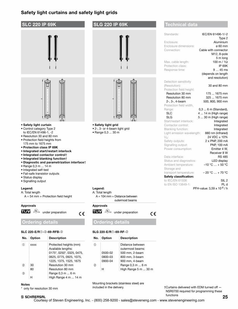
Safety light curtains and safety light grids
SLC 220 IP 69K
A
¤ 60
• Safety light curtain• Control category Type 2
to IEC/EN 61496-1, -2• Resolution 30 and 80 mm• Protection field heights from
175 mm to 1675 mm• Protection class IP 69K• Integrated start/restart interlock• Integrated contactor control†• Integrated blanking function†• Diagnostic and parametrization interface†• Range 0,3 m . . . 14 m• Integrated self-test• Fail-safe transistor outputs • Status display• Signalling output
Legend:A: Total length
A = 54 mm + Protection field height
Approvals
F under preparation
Ordering details
SLC 220-E/R➀-➁-69-RFB-➂
No. Option Description
➀ xxxx Protected heights (mm)Available lengths:0175*, 0250*, 0325, 0475,0625, 0775, 0925, 1075, 1225, 1375, 1525, 1675
➁ 30 Resolution 30 mm80 Resolution 80 mm
➂ Range 0,3 m . . . 6 mH High Range 4 m . . . 14 m
Notes* only for resolution 30 mm
Technical data
Standards: IEC/EN 61496-1/-2 Type 2Enclosure: AluminiumEnclosure dimensions: ø 60 mmConnection: Cable with connector
M12, 8-pole 5 m long
Max . cable length: 100 m / 1ΩProtection class: IP 69KResponse time: 9 … 45 ms
(depends on length and resolution)
Detection sensitivity (Resolution): 30 and 80 mmProtection field height:
Resolution 30 mm 175 . . . 1675 mmResolution 80 mm 325 . . . 1675 mm2-, 3-, 4-beam 500, 800, 900 mm
Protection field width, Range: 0,3 . . . 6 m (Standard),
SLC 4 . . . 14 m (High range)SLG 5 . . . 30 m (High range)
Start/restart interlock: IntegratedContactor control: IntegratedBlanking function: IntegratedLight emission wavelength: 880 nm (infrared)Ue: 24 VDC ± 10%Safety outputs: 2 x PNP, 200 mASignalling output: PNP, 100 mAPower consumption: Emitter 4 W,
Receiver 8 WData interface: RS 485Status and diagnostics: LED displayAmbient temperature: –10 °C … + 50 ºCStorage and transport temperature: – 20 °C … + 70 ºCSafety classification: to IEC/EN 61508: SIL 2to EN ISO 13849-1: PL d
PFH-value: 3,59 x 10⁻⁸ / h
SLG 220 IP 69K
A
¤ 60
• Safety light grid• 2-, 3- or 4-beam light grid• Range 0,3 . . . 30 m
Legend:A: Total length
A = 104 mm + Distance between outermost beams
Approvals
F under preparation
Ordering details
SLG 220-E/R➀-69-RF-➁
No. Option Description
➀ Distance between outermost beams:
0500-02 500 mm, 2-beam0800-03 800 mm, 3-beam0900-04 900 mm, 4-beam
➁ Range 0,3 m . . . 6 mH High Range 5 m . . . 30 m
Mounting brackets (stainless steel) are included in the delivery . † Curtains delivered with EDM turned off —
NSR0700 required for programming these functions
Courtesy of Steven Engineering, Inc. - (800) 258-9200 - [email protected] - www.stevenengineering.com

26
Safety light curtains and safety light grids
Technical data
Standards: IEC/EN 61496-1/-2 Type 4Enclosure: AluminiumEnclosure dimensions: ø 49 mmConnection: Connector
Emitter: Connector plug M12, 4-pole, Receiver: Connector plug M12, 8-pole
Max . cable length: 100 m / 1 ΩProtection class: IP 67 to EN 60529Response time: 10 … 27 ms
(depends on length and resolution)
Detection sensitivity (Resolution): 14, 30 and 50 mmProtection field height:
Resolution 14 mm 170 . . . 1450 mmResolution 30, 50 mm 170 . . . 1770 mm2-, 3-, 4-beam 500, 800, 900 mm
Protection field width, Range:Resolution 14 mm 0,3 m . . . 7 mResolution 30, 50 mm 0,3 m . . . 10 mHigh Range Resolution 30 mm 0,3 m . . . 18 m2-, 3-, 4-beam 0,3 m . . . 10 mHigh Range 2-, 3-, 4-beam 8 m . . . 40 m
Start/restart interlock: IntegratedContactor control: IntegratedBlanking function: IntegratedCascading: (Master/Slave) –Light emission wavelength: 880 nm (infrared)Ue: 24 VDC ± 10%Safety outputs: 2 x PNP, 500 mAPower consumption: Emitter 4 W,
Receiver 8 WData interface: RS 485Status and diagnostics: LED displayAmbient temperature: –10 °C … + 50 ºCStorage and transport temperature: – 20 °C … + 70 ºCSafety classification: to IEC 62061: SIL 3to EN ISO 13849-1: PL e
PFH-value: 7,42 x 10⁻⁹ / h
Ordering details
Connector:Connector plug for emitter M12, 4-pole straight Cable length 5 m KA-0804Cable length 10 m KA-0805Cable length 20 m KA-0808
Connector plug for receiver M12, 8-pole straightCable length 5 m KA-0904Cable length 10 m KA-0905Cable length 20 m KA-0908
SLC 420 standardA
¤ 49
• Safety light curtain• Control category Type 4
to IEC/EN 61496-1, -2• Resolution 14, 30 and 50 mm• Protection field heights from
170 mm to 1770 mm• Integrated start/restart interlock• Integrated contactor control†• Integrated blanking function (fixed and
mobile blanking)†• Diagnostic and parametrization interface†• Range 0,3 m . . . 18 m• Fail-safe transistor outputs • Optical synchronisation • Status display• Protection class IP 67
Legend:A: Total length
A = 84,5 mm + Protection field height
Approvals
F
Ordering details
SLC 420-E/R➀-➁-RFB-➂
No. Option Description
➀ xxxx Protected heights (mm)Available lengths:0170, 0250, 0330, 0410, 0490, 0570, 0650, 0730, 0810, 0890, 0970, 1050, 1130, 1210, 1290, 1370, 1450, 1530*, 1610*, 1690*, 1770*
➁ 14 Resolution 14 mm30 Resolution 30 mm50 Resolution 50 mm
➂ Range 0,3 m . . . 7 m**Range 0,3 m . . . 10 m *
H High Range 0,3 m . . . 18 m***
SLG 420 standard
A
¤ 49
• Safety light grid• 2-, 3- or 4-beam light grid• Range 0,3 . . . 40 m
Legend:A: Total length
2-beam A = 734,5 mm3 and 4-beam A = 1054,5 mm
Approvals
F
Ordering details
SLG 420-E/R➀-RF-➁
No. Option Description
➀ Distance between outermost beams:
0500-02 500 mm, 2-beam0800-03 800 mm, 3-beam0900-04 900 mm, 4-beam
➁ Range 0,3 m . . . 10 mH High Range 8 m . . . 40 m
Mounting brackets are included in the delivery .Notes* only for resolution 30 mm and 50 mm** only for resolution 14 mm*** only for resolution 30 mm
† Curtains delivered with EDM turned off — NSR0801 required for programming these functions
Courtesy of Steven Engineering, Inc. - (800) 258-9200 - [email protected] - www.stevenengineering.com

27
Safety light curtains and safety light grids
Technical data
Standards: IEC/EN 61496-1/-2 Type 4Enclosure: AluminiumEnclosure dimensions: ø 49 mmConnection: Connector plug
Master Emitter: M12, 4-pole, Master Receiver: M12, 8-poleSlave Emitter: M12, 4-pole, Slave Receiver: M12 1, 8-pole
Max . cable length: 100 m / 1 ΩMax . cable length: (Master/Slave) 0,8 mProtection class: IP 67 to EN 60529Response time: 10 … 37 ms
(Depends on length and resolution)
Detection sensitivity (Resolution): 14, 30 and 50 mmProtection field height:
Resolution 14 mm 170 . . . 2100 mmResolution 30, 50 mm 170 . . . 2420 mm
Protection field width, Range:Resolution 14 mm 0,3 m . . . 7 mResolution 30, 50 mm 0,3 m . . . 10 mHigh Range 30 mm 0,3 m . . . 18 m
Start/restart interlock: IntegratedContactor control: IntegratedBlanking function: IntegratedCascading: (Master/Slave) possibleLight emission wavelength: 880 nm (infrared)Ue: 24 VDC ± 10%Safety outputs: 2 x PNP, 500 mAPower consumption: Emitter 4 W,
Receiver 8 WData interface: RS 485Status and diagnostics: LED displayAmbient temperature: –10 °C … + 50 ºCStorage and transport temperature: – 20 °C … + 70 ºCSafety classification: to IEC 62061: SIL 3to EN ISO 13849-1: PL e
PFH-value: 7,42 x 10⁻⁹ / h
Ordering details
Mounting brackets are included in the delivery .
Notes* only for resolution 30 mm and 50 mm** only for resolution 14 mm*** Protection field heights from 170 . . . 650 mm
SLC 420 Master / Slave
A
¤ 49
• Safety light curtain• Control category Type 4to IEC/EN 61496-1, -2• Resolution 14, 30 and 50 mm• Protection field height:
Master from 170 mm to 1770 mmSlave from 170 mm to 650 mm
• Integrated start/restart interlock• Integrated contactor control†• Integrated blanking function†• Diagnostic and parametrization interface†• Cascading of Master and Slave devices • Range 0,3 m . . . 7 m or 0,3 m . . . 10 m• Fail-safe transistor outputs • Optical synchronisation • Status display
Legend:A: Total length
A = 84,5 mm + Protection field height
Approvals
F
Ordering details
SLC 420-E/R➀-➁-RFB-➂➃
No. Option Description
➀ xxxx Protected heights (mm)Available lengths:0170, 0250, 0330, 0410, 04900570, 0650, 0730, 0810, 08900970, 1050, 1130, 1210, 12901370, 1450, 1530*, 1610*,1690*, 1770*
➁ 14 Resolution 14 mm30 Resolution 30 mm50 Resolution 50 mm
➂ Range 0,3 m . . . 7 m**Range 0,3 m . . . 10 m*
H High Range 0,3 m . . . 18 m,➃ M Master function
S*** Slave function
Ordering details
Connector:Connector plug for emitter M12, 4-pole straight Cable length 5 m KA-0804Cable length 10 m KA-0805Cable length 20 m KA-0808Connector plug for receiver M12, 8-pole straightCable length 5 m KA-0904Cable length 10 m KA-0905Cable length 20 m KA-0908Connector plug for Master/Slave connection Emitter2 x M12, 4-pole straightCable length 0,8 m KA-0810Receiver2 x M12 x 1, 8-pole straightCable length 0,8 m KA-0901
† Curtains delivered with EDM turned off — NSR0801 required for programming these functions
30 mm resolution only
Courtesy of Steven Engineering, Inc. - (800) 258-9200 - [email protected] - www.stevenengineering.com

28
Safety light curtains and safety light grids
SLC 420 IP 69KA
¤ 60
• Safety light curtain• Control category Type 4
to IEC/EN 61496-1, -2• Resolution 14 mm and 30 mm• Protection field heights from
170 mm to 1450 mm• Protection class IP 69K• Integrated start/restart interlock• Integrated contactor control† • Integrated blanking function (fixed and
mobile blanking)†• Diagnostic and parametrization interface†• Range 0,3 m . . . 10 m• Fail-safe transistor outputs • Optical synchronisation • Status display
Legend:A: Total length
A = 97 mm + Protection field height
Approvals
F under preparation
Ordering detailsSLC 420-E/R➀-➁-69-RFB
No. Option Description
➀ xxxx Protected heights (mm)Available lengths:0170, 0250, 0330, 0410, 0490, 0570, 0650, 0730, 0810, 0890, 0970, 1050, 1130, 1210, 1290, 1370, 1450
➁ 14 Resolution 14 mm with arange of 0 .3 m …7 m
30 Resolution 30 mm with arange of 0 .3 m …10 m
Technical dataStandards: IEC/EN 61496-1/-2 Type 4Enclosure: AluminiumEnclosure dimensions: ø 60 mmConnection:
Emitter/Receiver: Cable gland PG 9, Receiver Cable length 5 meter, Emitter Cable length 5 meter, Gore TM Membrane M12
Max . cable length: 100 m / 1 ΩProtection class: IP 69 to EN 60529
Response time: 10 … 27 ms (depends on length
and resolution)Detection sensitivity (Resolution): 14, 30 mmProtection field height:
Resolution 14, 30 mm 170 . . . 1770 mm2-, 3-, 4-beam 500, 800, 900 mm
Protection field width, Range: Resolution 14 mm 0,3 m . . . 7 mResolution 30 mm 0,3 m . . . 10 m2-, 3-, 4-beam 0,3 m . . . 10 m
Start/restart interlock: IntegratedContactor control: IntegratedBlanking function: IntegratedCascading: (Master/Slave) –Light emission wavelength: 880 nm (infrared)Ue: 24 VDC ± 10%Safety outputs: 2 x PNP, 500 mAPower consumption: Emitter 4 W,
Receiver 8 WData interface: RS 485Status and diagnostics: LED displayAmbient temperature: –10 °C … + 50 ºCStorage and transport temperature: – 20 °C … + 70 ºCSafety classification: to IEC 62061: SIL 3to EN ISO 13849-1: PL e
PFH-value: 7,42 x 10⁻⁹ / h
NotesDelivered with cable gland and 5 m cable
SLG 420 IP 69K
A
¤ 60
• Safety light grid• 2-, 3- or 4-beam light grid• Range 0,3 . . . 12 m
Legend:A: Total length
2-beam A = 747 mm3 and 4-beam A = 1067 mm
Approvals
F under preparation
Ordering details SLG 420-E/R➀-69-RF
No. Option Description
➀ Distance between outermost beams:
0500-02 500 mm, 2-beam0800-03 800 mm, 3-beam0900-04 900 mm, 4-beam
Mounting brackets (stainless steel) are included in the delivery .
†Curtains delivered with EDM turned off — NSR0801 required for programming these functions
Courtesy of Steven Engineering, Inc. - (800) 258-9200 - [email protected] - www.stevenengineering.com
29
Safety light curtains and safety light grids
Ordering detailsConnector:Connector plug M12, 8-pole straightCable length 5 m KA-0904Cable length 10 m KA-0905Cable length 20 m KA-0908
Mounting brackets are included in the delivery .
Technical data
Standards: IEC/EN 61496-1/-2 Type 4Enclosure: AluminiumEnclosure dimensions: ø 49 mmDeflecting mirror: 50 x50 x 606 mmConnection: Connector plug
Emitter/Receiver: M12, 8-poleMax . cable length: 100 m / 1 ΩProtection class: IP 67 to EN 60529Response time: 10 ms Detection sensitivity (Resolution): 500 mmProtection field height: 2-beam 500 mm
Protection field width, Range: 2-beam 0,3 m . . . 7 m
Start/restart interlock: IntegratedContactor control: IntegratedLight emission wavelength: 880 nm
(infrared)Ue: 24 VDC ± 10%Safety outputs: 2 x PNP, 500 mAPower consumption: 10 WData interface: –Status and diagnostics: LED displayAmbient temperature: –10 °C … + 50 ºCStorage and transport temperature: – 20 °C … + 70 ºCSafety classification: to IEC 62061: SIL 3to EN ISO 13849-1: PL e
PFH-value: 7,42 x 10⁻⁹ / h
SLG 422-P734,5
¤ 49 50 50
606
• Safety light grid• Emitter and receiver in one enclosure
(retro reflector)• Control category Type 4
to IEC/EN 61496-1, -2• Protection field heights 500 mm• 2-beam light grid • Integrated start/restart interlock• Integrated contactor control† • Range 0,3 m . . . 7 m• Fail-safe transistor outputs • Status display• Protection class IP 67
Approvals
F
Ordering detailsSLG 422-P-E/R0500-02-RF Safety light grid
ULS-P-0500 Deflecting mirror
† Curtains delivered with EDM turned off — NSR0801 required for programming these functions
Courtesy of Steven Engineering, Inc. - (800) 258-9200 - [email protected] - www.stevenengineering.com

30
Miniaturized safety light grids and safety light curtains
Technical data
Standards: IEC/EN 61496-1/-2Control Category: Type 4
in combination with evaluation unit NSR-0605
Enclosure: AluminiumEnclosure dimensions: 12 x 20 mmConnection: Connector M8, 4-poleMax . cable length: 100 m / 1 ΩProtection class: IP 65 to EN 60529Response time including relay output: 50 ms Detection sensitivity (Resolution): 30 mmProtection field height: 236 . . . 1804 mmProtection field width, Range: 0,3 m . . . 3,5 m
Start/restart interlock: IntegratedContactor control: IntegratedLight emission wavelength: 880 nm (infrared)Ue: 22 . . . 30 VDC
18 . . . 25 VACPower consumption: 8 W
SystemData interface: RS 485Status and diagnostics: LED displayAmbient temperature: 0 °C … + 50 ºCStorage and transport temperature: – 10 °C … + 70 ºCSafety outputs: 2 x Relay contact 250 V / 4 ASignalling output: 1 x Relay contact 42 V / 4 A
Ordering detailsConnector:Connector plug for ermitter / receiver M8, 4-pole straightCable length 5 m KA-0610Cable length 10 m KA-0611
SLC 430
• Safety light curtain• Control category Type 4
to IEC/EN 61496-1, -2• Resolution 30 mm• Protection field heights from
236 mm to 1804 mm• slim design, size 12 x 20 mm• Integrated start/restart interlock• Integrated contactor control • Range 0,3 m . . . 3,5 m• Status display• Protection class IP 65
Approvals
F
Ordering details
SLC 430-E/R➀-30-RF-SYS
No. Option Description
➀ xxxx Protected heights (mm)Available lengths:0236, 0460, 0684, 0908, 1132, 1356, 1580, 1804
* Range up to 5 m upon request
Included in deliveryEmitter and receiver including mounting set, controller NSR-0605, cable set KA-0610 (cable length 5 m)
NSR-0605
• Safety controllerEnclosure dimensions: 240 x 160 mm
Courtesy of Steven Engineering, Inc. - (800) 258-9200 - [email protected] - www.stevenengineering.com
31
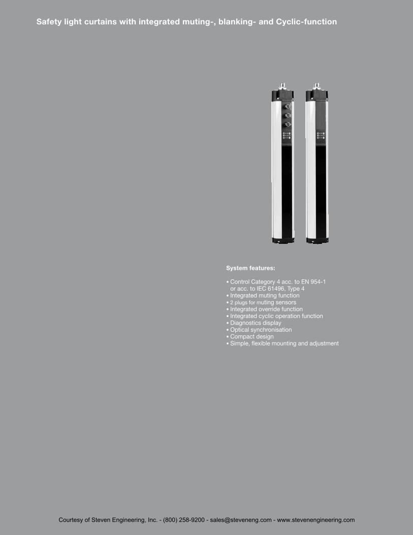
System features:
• Control Category 4 acc . to EN 954-1 or acc . to IEC 61496, Type 4
• Integrated muting function• 2 plugs for muting sensors• Integrated override function• Integrated cyclic operation function• Diagnostics display• Optical synchronisation• Compact design• Simple, flexible mounting and adjustment
Safety light curtains with integrated muting-, blanking- and Cyclic-function
Courtesy of Steven Engineering, Inc. - (800) 258-9200 - [email protected] - www.stevenengineering.com
32
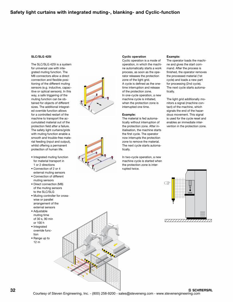
SLC/SLG 425I
The SLC/SLG 425I is a system for universal use with inte-grated muting function . The M8 connectors allow a direct connection and flexible posi-tioning of the different muting sensors (e .g . inductive, capac-itive or optical sensors) . In this way, a safe triggering of the muting function can be ob-tained for objects of different sizes . The additional integrat-ed override function allows for a controlled restart of the machine to transport the ac-cumulated material out of the protection field after a failure . The safety light curtains/grids with muting function enable a smooth and trouble-free mate-rial feeding (input and output), whilst offering a permanent protection of human life .
• Integrated muting function for material transport in 1 or 2 directions
• Connection of 2 or 4 external muting sensors
• Connection of different muting sensors
• Direct connection (M8) of the muting sensors to the SLC/SLG
• Muting controller for cross-wise or parallel arrangement of the external sensors
• Adjustable muting time of 30 s, 90 min or 100 h
• Integrated override func-tion
• Range up to 12 m
Safety light curtains with integrated muting-, blanking- and Cyclic-function
Cyclic operationCyclic operation is a mode of operation, in which the machi-ne automatically starts a work process, as soon as the ope-rator releases the protection zone of the light grid .A cycle is defined as the one-time interruption and release of the protection zone .In one-cycle operation, a new machine cycle is initiated, when the protection zone is interrupted one time .
Example: The material is fed automa-tically without interruption of the protection zone . After in-itialisation, the machine starts the first cycle . The operator now interrupts the protection zone to remove the material . The next cycle starts automa-tically .
In two-cycle operation, a new machine cycle is started when the protection zone is inter-rupted twice .
Example: The operator loads the machi-ne and gives the start com-mand . After the process is finished, the operator removes the processed material (1st cycle) and loads a new part for processing (2nd cycle) . The next cycle starts automa-tically .
The light grid additionally mo-nitors a signal (machine con-tact) of the machine, which signals the end of the hazar-dous movement . This signal is used for the cycle reset and enables an immediate inter-vention in the protection zone .
Courtesy of Steven Engineering, Inc. - (800) 258-9200 - [email protected] - www.stevenengineering.com

33
Safety light curtains with integrated muting-, blanking- and Cyclic-function
Technical data
Standards: IEC/EN 61496-1/-2 Type 4Enclosure: AluminiumEnclosure dimensions: ø 49 mmConnection: Connector plug
Emitter: M12, 4-pole, Receiver: M12, 8-pole,Muting sensors: 2 x connector plugs
M8, 3-poleMuting lamp: M8, 3 polig
Max . cable length: 100 m / 1 ΩProtection class: IP 67 to EN 60529Response time: 7 … 28,5 ms
(Depends on length and resolution)
Detection sensitivity (Resolution): 14 and 30 mmProtection field height:
Resolution 14 mm 170 . . . 1450 mmResolution 30 mm 170 . . . 1770 mm2-, 3-, 4-beam 500, 800, 900 mm
Protection field width, Range:Resolution 14 mm 0,3 m . . . 7 m Resolution 30 mm 0,3 m … 10 m 2-, 3- . 4-beam 0,3 m . . . 18 m
Start/restart interlock: IntegratedContactor control: IntegratedMuting- and Override-Funktion: IntegratedMuting sensors: 2 or 4 external
sensors Light emission wavelength: 880 nm (infrared)Ue: 24 VDC ± 10%Safety outputs: 2 x PNP, 500 mAPower consumption: Emitter 4 W,
Receiver 8 WData interface: RS 485Status and diagnostics: LED displayAmbient temperature: –10 °C … + 50 ºCStorage and transport temperature: – 20 °C … + 70 ºCSafety classification: to IEC 62061: SIL 3to EN ISO 13849-1: PL e
PFH-value: 7,42 x 10⁻⁹ / h
Ordering detailsConnector:Connector plug for emitter M12, 4-pole straight Cable length 5 m KA-0804Cable length 10 m KA-0805Cable length 20 m KA-0808
Connector plug for receiver M12, 8-pole straightCable length 5 m KA-0904Cable length 10 m KA-0905Cable length 20 m KA-0908
Connector plug for muting sensors M12x1, 4 pole to M8x1, 3 poleCable length 2m KA-0965For connection to SLC/G 425I
SLC 425I
A
• Safety light curtain• Control category Type 4 to IEC/EN 61496-1, -2• Resolution 14 and 30 mm • Protection field heights from 170 mm to 1770 mm• Integrated start/restart interlock• Integrated contactor control†• Integrated muting and override function†• Integrated blanking function (fixed and
mobile blanking)†• Cyclic operation (1 ... 8 Cycles)• Range 0,3 . . . 10 m• Fail-safe transistor outputs • Optical synchronisation • Status display• Different muting sequences can be parameterized• Protection class IP 67Legend:A: Total length
EmitterA = 84,5 mm + Protection field height Receiver A = 148,5 mm + Protection field height
Approvals
F
Ordering details
SLC 425I-E/R➀-➁-RFBC
No. Option Description
➀ xxxx Protected heights (mm)Available lengths:0170, 0250, 0330, 0410, 0490, 0570, 0650, 0730, 0810, 0890, 0970, 1050, 1130, 1210, 1290, 1370, 1450, 1530*, 1610*, 1690*, 1770*
➁ 14, 30 Resolution 14 mm, 30 mm
SLG 425I
A
• Safety light grid• 2-, 3- or 4-beam light grid • Protection field heights 500, 800 or 900 mm• Range 0,3 . . . 18 m
Legend:A: Total length
Emitter 2-beam A = 804 mm 3 and 4-beam A = 1124 mm Receiver 2-beam A = 868 mm 3 and 4-beam A = 1188 mm
Approvals
F
Ordering details
SLG 425I-E/R➀-RFBC
No. Option Description
➀ Distance between outermost beams:
0500-02 500 mm, 2-beam0800-03 800 mm, 3-beam0900-04 900 mm, 4-beam
* only for resolution 30 mmMounting brackets are included in the delivery .
†Curtains delivered with EDM turned off — NSR0801 required for programming these functions
Courtesy of Steven Engineering, Inc. - (800) 258-9200 - [email protected] - www.stevenengineering.com
34
Safety light curtains with integrated muting-, blanking- and Cyclic-function
Technical data
Ordering detailsConnector:Connector plug M12, 8-pole straightCable length 5 m KA-0904Cable length 10 m KA-0905Cable length 20 m KA-0908
Mounting brackets are included in the delivery .
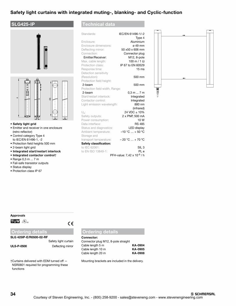
Standards: IEC/EN 61496-1/-2 Type 4Enclosure: AluminiumEnclosure dimensions: ø 49 mmDeflecting mirror: 50 x50 x 606 mmConnection: Connector plug
Emitter/Receiver: M12, 8-poleMax . cable length: 100 m / 1 ΩProtection class: IP 67 to EN 60529Response time: 15 ms Detection sensitivity (Resolution): 500 mmProtection field height: 2-beam 500 mm
Protection field width, Range: 2-beam 0,3 m . . . 7 m
Start/restart interlock: IntegratedContactor control: IntegratedLight emission wavelength: 880 nm
(infrared)Ue: 24 VDC ± 10%Safety outputs: 2 x PNP, 500 mAPower consumption: 10 WData interface: RS 485Status and diagnostics: LED displayAmbient temperature: –10 °C … + 50 ºCStorage and transport temperature: – 20 °C … + 70 ºCSafety classification: to IEC 62061: SIL 3to EN ISO 13849-1: PL e
PFH-value: 7,42 x 10⁻⁹ / h
A
50¤49 50
606
SLG425-IP
• Safety light grid• Emitter and receiver in one enclosure
(retro reflector)• Control category Type 4
to IEC/EN 61496-1, -2• Protection field heights 500 mm• 2-beam light grid • Integrated start/restart interlock• Integrated contactor control†• Range 0,3 m . . . 7 m• Fail-safe transistor outputs • Status display• Protection class IP 67
Approvals
F
Ordering detailsSLG 425IP-E/R0500-02-RF Safety light curtain
ULS-P-0500 Deflecting mirror
† Curtains delivered with EDM turned off — NSR0801 required for programming these functions
Courtesy of Steven Engineering, Inc. - (800) 258-9200 - [email protected] - www.stevenengineering.com

35
Safety light curtains with integrated diagnostics and parameter setting
4-21
SLC 440-E/R--01No. Option Description
xxxx Protected heights (mm) available lengths: 0170, 0250, 0330, 0410, 0490, 0570, 0650, 0730, 0810, 0890, 0970, 1050, 1130, 1210, 1290*, 1370*, 1450*, 1530*, 1610*, 1690*, 1770*
14 Resolution 14 mm with a range of 0.3 m ... 7 m
30 Resolution 30 mm with a range of 0.3 m ... 10 m
-01 = integrated status indication (option)* only for resolution 30 mm
Connector: Female connector M12, 4-pole straight for emittercable length 5 m 101207741cable length 10 m 101207742cable length 20 m 101207743Female connector M12, 8-pole straight for receivercable length 5 m 101207728cable length 10 m 101207729cable length 20 m 101207730
Cable for the parametrizationcable length 1 m 101217615
SLG 440-E/R-01No. Option Description
Distance between outermost beams:0500-02 500 mm, 2-beam0800-03 800 mm, 3-beam0900-04 900 mm, 4-beam
Range 0.3 … 12 m
-01 = integrated status indication (option)
Safety light curtains and safety light grids
SLC 440
A
3327,8
• Safety light curtain• Type 4 to EN 61496-1, CLC/TS 61496-2• Resolution 14 and 30 mm• Protection field heights 170 mm ... 1770 mm• Integrated start/restart interlock• Integrated contactor control• Integrated blanking function
(fixed and mobile blanking)• Diagnostic and parametrization interface• Range 0,3 m ... 10 m• Fail-safe transistor outputs• Optical synchronisation• LED Status display, 7-segment display• Protection class IP67
Legend: A = Total lengthA = 81 mm + Protection field height
Approvals
F
Ordering details
Technical dataStandards: EN 61496-1; CLC/TS 61496-2Category: Type 4Enclosure: aluminiumEnclosure dimensions: 27.8 x 33 mmConnection: Connector plug- Emitter: M12, 4-pole,- Receiver: M12, 8-poleMax. cable length: 100 m / 1 ΩProtection class: IP67 to EN 60529Response time: 10 … 27 ms (depends on
length and resolution)Detection sensitivity(Resolution): 14 and 30 mmProtection field height:- Resolution 14 mm 170 ... 1210 mm- Resolution 30 mm 170 ... 1770 mm- 2-, 3-, 4-beam 500, 800, 900 mmProtection field width, Range:- Resolution 14 mm 0.3 m ... 7 m- Resolution 30 mm 0.3 m ... 10 m- 2-, 3-, 4-beam 0.3 m ... 12 mStart/restart interlock: IntegratedContactor control: IntegratedBlanking function: IntegratedLight emission wavelength: 880 nm (infrared)Ue: 24 VDC ± 10%Safety outputs: 2 x PNP, 250 mAPower consumption: Emitter 1,8 W,
Receiver 3,8 WStatus and diagnostics: LED-,
7-segment display Ambient temperature: −10 °C … +50 °CStorage andtransport temperature: −25 °C … +70 °CClassification:Standards: EN ISO 13849-1; EN 62061PL: up to eCategory: up to 4PFH-value: - SLC 440 11,4 x 10⁻⁹ /h- SLG 440 8,14 x 10⁻⁹ /hSIL: up to 3Service life: 20 years
Ordering details
Approvals
F
Ordering details
SLG 440
A
3327,8
• Safety light grid• 2-, 3- or 4-beam light grid• Range 0,3 ... 12 m
Legend: A = Total length2-beam A = 610 mm3-beam A = 910 mm4-beam A = 1010 mm
Courtesy of Steven Engineering, Inc. - (800) 258-9200 - [email protected] - www.stevenengineering.com

36
Safety light curtains and safety light grids – accessories
System components
MS-1010 Mounting kit
MS-1031 Mounting kit for ULS-A4
MS-1036 Mounting kit
Mounting kit MS-1051
Ordering details
Mounting kit for central fixation for SLC /SLG 2202 x angle MS-1010Mounting kit for ULS-A42 x incl . screws MS-1031MS-1036 Mounting kit for SLC/SLG 420-425 in V4A4 x incl . screws MS-1036Mounting kit lateral fixation for SLC/SLG 420-425Consisting of 2 steel angles, 4 screws and 4 T-slot nuts MS-1051
System components
Mounting kit MS-1073
Mounting kit MS-690
Vibration damper MSD-2 / MSD-4
Test rod PLS-01, PLS-02
Ordering details
Mounting kit for deflecting mirror ULS-M2 x mounting angle MS-1073 Mounting kit for SLC 4302 x clamping profile MS-690Vibration damper8 x vibration damper for SLC/SLG 220 MSD-28 x vibration damper for SLC/SLG 420-425 MSD-4Test rod for resolution 30mm PLS-01Test rod for resolution 14mm PLS-02
Alignment kit EA-5
Yellow lighting element with wall support
MS-1000
System components
Ordering details
Laser alignment tool for SLC / SLG series EA5 Muting lamp with LED block MK2 Operating conditions indication red, green, yellow LED MK3Operating conditions indication red, green MK4Signalling lamp with bulb 24 V yellow with wall mounting bracket MK5Mounting kit for SLC /SLG 2204 x angle incl . screws MS-1000 2 x angle incl . screws MS 1072
Courtesy of Steven Engineering, Inc. - (800) 258-9200 - [email protected] - www.stevenengineering.com

37
Safety light curtains and safety light grids – accessories
System components
Deflecting mirror ULS-A4, ø 49 mm
Mounting Stands
Muting Carrier Set
Ordering detailsDeflecting mirror ULS-A4 incl. mounting angleMirror height 200 mm ULS-A4-0200Mirror height 400 mm ULS-A4-0400Mirror height 550 mm ULS-A4-0550Mirror height 700 mm ULS-A4-0700Mirror height 850 mm ULS-A4-0850Mirror height 1000 mm ULS-A4-1000Mounting StandsHeight including plinth 500mm MST-0500Height including plinth 750mm MST-0750Height including plinth 1000mm MST-1000Height including plinth 1250mm MST-1250Height including plinth 1500mm MST-1500Height including plinth 1750mm MST-1750Height including plinth 2000mm MST-2000Muting Carrier Set2 x Aluminium profile MT-0400
System components
Protective enclosure with deflecting mirror
Protective enclosure for light grids
Aluminium profile for SLC 430
Ordering detailsProtective enclosure with deflecting mirror version for 2-beam light grids ULS-ST2version for 3-beam light grids ULS-ST3version for 4-beam light grids ULS-ST4Protective enclosure for light gridsHeight 1114mm hot-dip galvanised SG1Height 1334 mm hot-dip galvanised SG2Height 1114 mm RAL 1021 SG3Height 1334 mm RAL 1021 SG4 Aluminium profile for SLC 4302 x profile, length 420 mm MS- 15012 x profile, length 643 mm MS- 15022 x profile, length 865 mm MS- 15032 x profile, length 1090 mm MS- 15042 x profile, length 1312 mm MS- 15052 x profile, length 1537 mm MS- 15062 x profile, length 1761 mm MS- 15072 x profile, length 1985 mm MS- 1508
System components
NSR-0801
NSR-0700
Deflecting mirror ULS-M
Deflection Mirror Application NotesULS-M: Must be used when range is greater than 6m . With 1 mirror, range reduced by 10%, with 2 or more mirrors range reduced by 15% for each mirror .
ULS-A4: Must be used when range is less than 6m . With a loss of 20% at each mirror, only 1 mirror per emitter/receiver pair is recommended .
Ordering detailsBus converterConverter for programming of SLC/SLG 420-425 Schnittstelle USB 2 .0 NSR 0801Converter for programming of SLC / SLG 220 RS232 interface NSR 0700Deflecting mirror ULS-M incl. mounting angleMirror height 200mm ULS-M-0200Mirror height 350mm ULS-M-0350Mirror height 500mm ULS-M-0500Mirror height 650mm ULS-M-0650Mirror height 800mm ULS-M-0800Mirror height 950mm ULS-M-0950Mirror height 1250mm ULS-M-1250Mirror height 1550mm ULS-M-1550Mirror height 1700mm ULS-M-1700
Courtesy of Steven Engineering, Inc. - (800) 258-9200 - [email protected] - www.stevenengineering.com

38
Reflection light sensor (Muting sensor)
4-23
Safety light curtains and safety light grids
LF 50-11P
46 4416
4
4
17
4,3
4,3
13,5
63,5
4440
50
M 12x1
• Range up to 5.5 m• Connector plug can be rotated• LED status display• Protection class IP67• Infrared light 660 nm• Laser protection class 1• Polarisation filter• Antivalent switching outputs
Approvals
Ordering detailsLF 50-11P
Note:System components (cables, mounting angles, etc.) not included in the delivery.
Technical dataStandards: EN 60974-5-2Laser protection class 1 EN 60825-1-10/03Enclosure: ABSEnclosure dimensions: 50 x 50 x 17 mmConnection: Connector plug
M12, 4-pole, can be rotated
Max. cable length: 100 mProtection class: IP67Switching frequency: 2500 HzRange: 0 ... 5.5 mInfrared laser light: 660 nmUe: 10 ... 30 VDCSwitching output: 2 x PNP 200 mABeam diameter: 5 ... 24 mmLED status display: soiling,
switching conditionand power on
Ambient temperature: −20 °C ... +60 °CStorage andtransport temperature: −20 °C … +80 °C
Ordering detailsConnectorM12, 4-pole, without cable 101208522M12, 4-pole, cable length 2 m 101209937M12, 4-pole, cable length 5 m 101209918 Connecting cable KA-0965to connect SLG 425IM12, 4-pole to M8, 3-pole, 2 m 101210312
System components
Ordering detailsReflector R 51 x 61-LReflector R D83Mounting angle BF 50Mounting angle universal BF UNI 1
Reflector R 51 x 61-L
Reflector R D83
Mounting angle BF 50
Mounting angle BF UNI 1
Courtesy of Steven Engineering, Inc. - (800) 258-9200 - [email protected] - www.stevenengineering.com

39
Overview of the Features Apart from the conventional safety controllers, the Schmersal Group also offers microprocessor-controlled safety technology . Depending on the complexity and the number of safety circuits, integral solutions comprised of safety monitoring modules, programmable safety controls or safety field bus systems featuring visualization and diagnostic possibilities are available .
Safety monitoring modules for optoelectronic safety components
Courtesy of Steven Engineering, Inc. - (800) 258-9200 - [email protected] - www.stevenengineering.com

40
SRB 301LC/B
• Suitable for signal processing of potential-free outputs, e .g . emergency stop command devices, position switches and solenoid interlocks
• Suitable for signal processing from the outputs of magnetic safety switches (to this end, equipped with built-in current and voltage limitation)
• Suitable for signal processing of outputs connected to potentials (AOPD’s), e .g . safety light grids/curtains
• 1 or 2 channel control• 3 safety contacts, STOP 0• 1 signalling output (NC)• Manual reset without edge detection• Automatic reset function• 4 LEDs to show operating conditions• Category 4 to EN 954-1
Approvals
H
Ordering detailsSRB 301LC/B-24V
Technical data
Standards: IEC/EN 60204-1, IEC/EN 60947-5-1,EN 954-1, BG-GS-ET-20
Product utilisation up to category in accordance with EN 954-1: 4Start conditions: Automatic or start buttonFeedback circuit (Y/N): yesON delay with reset button: ≤ 30 msDrop-out delay in case of emergency stop: ≤ 300 msDrop-out delay in case of power failure: ≤ 50 msRated operating voltage Ue: 24 VDC –15%/+20%, residual ripple max . 10%;
24 VAC –15%/+10%Rated operating current Ie: 0 .08 AFrequency range: 50 / 60 HzFuse rating for the operating voltage: 0 .5 A gG D fuseInternal electronic protection (Y/N): noPower consumption: 2 .1 W; 3 .0 VAMonitored inputs:
Short-circuit recognition: noWire breakage detection: yesEarth connection detection: yes
Number of NC contacts: 2Number of NO contacts: 0Max . conduction resistance: 40 ΩOutputs: Stop category 0: 3Stop category 1: 0Number of safety contacts: 3Number of signalling outputs: 1Max . switching capacity of the safety contacts: 250 VAC, 6 A ohmic (inductive in
case of appropriate protective wiring)Utilisation category to EN 60947-5-1: AC-15: 230 V / 6 A
DC-13: 24 V / 6 AMechanical life: 107 operationsAmbient conditions: Environmental temperature: – 25°C … + 45°CStorage and transport temperature: – 25°C … + 70°CProtection class: Enclosure: IP 40, Terminals: IP 20, Clearance: IP 54Mounting: Snaps onto standard DIN rail to EN 60715Connection type: Screw connection, solid strand or
multi-strand (incl . conductor ferrules)min . cable section: 0 .25 mm2
max . cable section: 2 .5 mm2
Weight: 230 gDimensions (Height/Width/Depth): 100 x 22 .5 x 121 mmNote: Inductive loads (e .g . contactors, relays, etc .) are
to be suppressed by means of a suitable circuit .
NoteFor some applications, the use of a monitored start button (reset with edge detection) is required .
Safety monitoring modules for optoelectronic safety components
Courtesy of Steven Engineering, Inc. - (800) 258-9200 - [email protected] - www.stevenengineering.com
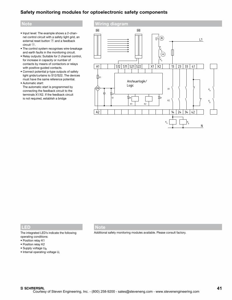
41
Note
• Input level: The example shows a 2-chan-nel control circuit with a safety light grid, an external reset button J and a feedback circuit S .
• The control system recognises wire-breakage and earth faults in the monitoring circuit .
• Relay outputs: Suitable for 2 channel control, for increase in capacity or number of contacts by means of contactors or relays with positive-guided contacts .
• Connect potential p-type outputs of safety light grids/curtains to S12/S22 . The devices must have the same reference potential .
• Automatic start: The automatic start is programmed by connecting the feedback circuit to the terminals X1/X2 . If the feedback circuit is not required, establish a bridge
LEDThe integrated LED’s indicate the followingoperating conditions:• Position relay K1• Position relay K2• Supply voltage UB• Internal operating voltage Ui
Wiring diagram
A2
A1 S12 S11 S21 S22 X1 X2 13
L1
33 4123
K2K1
UiK2
K1
F1
Ansteuerlogik/Logic
14 24 34 42
N
S
J
KA
KB
KA
KB
KB
KA
NoteAdditional safety monitoring modules available . Please consult factory .
Safety monitoring modules for optoelectronic safety components
Courtesy of Steven Engineering, Inc. - (800) 258-9200 - [email protected] - www.stevenengineering.com
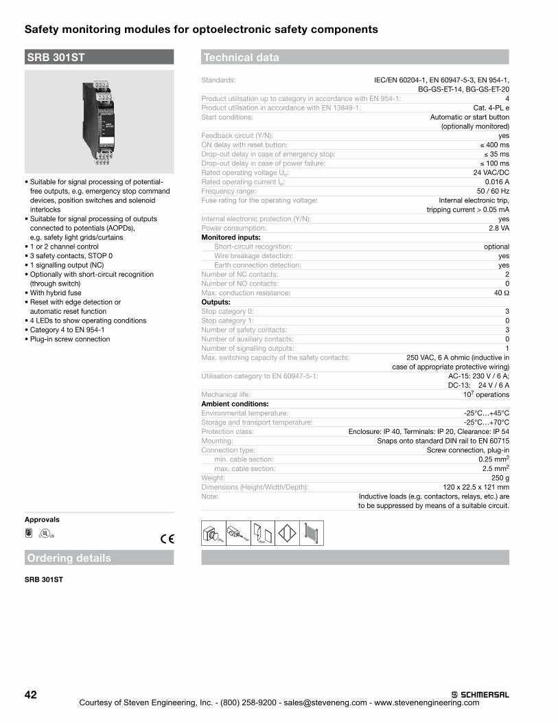
42
SRB 301ST
• Suitable for signal processing of potential-free outputs, e .g . emergency stop command devices, position switches and solenoid interlocks
• Suitable for signal processing of outputs connected to potentials (AOPDs), e .g . safety light grids/curtains
• 1 or 2 channel control• 3 safety contacts, STOP 0• 1 signalling output (NC)• Optionally with short-circuit recognition
(through switch)• With hybrid fuse• Reset with edge detection or
automatic reset function• 4 LEDs to show operating conditions• Category 4 to EN 954-1• Plug-in screw connection
Approvals
H
Ordering details
SRB 301ST
Technical data
Standards: IEC/EN 60204-1, EN 60947-5-3, EN 954-1, BG-GS-ET-14, BG-GS-ET-20
Product utilisation up to category in accordance with EN 954-1: 4Product utilisation in accordance with EN 13849-1: Cat . 4-PL eStart conditions: Automatic or start button
(optionally monitored)Feedback circuit (Y/N): yesON delay with reset button: ≤ 400 msDrop-out delay in case of emergency stop: ≤ 35 msDrop-out delay in case of power failure: ≤ 100 msRated operating voltage Ue: 24 VAC/DCRated operating current Ie: 0 .016 AFrequency range: 50 / 60 HzFuse rating for the operating voltage: Internal electronic trip,
tripping current > 0 .05 mAInternal electronic protection (Y/N): yesPower consumption: 2 .8 VAMonitored inputs:
Short-circuit recognition: optionalWire breakage detection: yesEarth connection detection: yes
Number of NC contacts: 2Number of NO contacts: 0Max . conduction resistance: 40 ΩOutputs: Stop category 0: 3Stop category 1: 0Number of safety contacts: 3Number of auxiliary contacts: 0Number of signalling outputs: 1Max . switching capacity of the safety contacts: 250 VAC, 6 A ohmic (inductive in
case of appropriate protective wiring)Utilisation category to EN 60947-5-1: AC-15: 230 V / 6 A;
DC-13: 24 V / 6 AMechanical life: 107 operationsAmbient conditions: Environmental temperature: -25°C…+45°CStorage and transport temperature: -25°C…+70°CProtection class: Enclosure: IP 40, Terminals: IP 20, Clearance: IP 54Mounting: Snaps onto standard DIN rail to EN 60715Connection type: Screw connection, plug-in
min . cable section: 0 .25 mm2
max . cable section: 2 .5 mm2
Weight: 250 gDimensions (Height/Width/Depth): 120 x 22 .5 x 121 mmNote: Inductive loads (e .g . contactors, relays, etc .) are
to be suppressed by means of a suitable circuit .
Safety monitoring modules for optoelectronic safety components
Courtesy of Steven Engineering, Inc. - (800) 258-9200 - [email protected] - www.stevenengineering.com

43
Note
• Input level: The example shows a 2-chan-nel control circuit with a safety light grid, an external reset button J and a feedback circuit S .
• The control recognises cross-short, cable break and earth leakages in the monitoring circuit .
• F1 = hybrid fuse • Relay outputs: Suitable for 2 channel control,
for increase in capacity or number of contacts by means of contactors or relays with positive-guided contacts .
• Switch setting: The cross-wire short detection function (factory default) is programmed by means of the switch located underneath the front cover of the module: Position nQS (top): no cross-wire short protection, suitable for 1-channel applications and applications with outputs with potential in the control circuits . Position QS (bottom): cross-wire short protection, suitable for 2-channel applications without outputs with potential in the control circuits .
• Connect potential p-type outputs of safety light grids/curtains to S12/S22 . The devices must have the same reference potential . (QS-switch = nQS)
• Automatic start: The automatic start is programmed by connecting the feedback circuit to the terminals S12/X3 . If the feedback circuit is not required, establish a bridge
LEDThe integrated LED’s indicate the followingoperating conditions:• Position relay K1• Position relay K2• Supply voltage UB• Internal operating voltage Ui
Wiring diagram
K1 K2
F1
UB Ui
A1 S12 S11 S21
L1
K1
K2
13 23S22
A2 14 24
33
34
41
Ansteuerlogik/Logic
nQS
QS
SJ
42
N
X3 X2
KA
KB
KB
KB
KA
KA
NoteAdditional safety monitoring modules available . Please consult factory .
Safety monitoring modules for optoelectronic safety components
Courtesy of Steven Engineering, Inc. - (800) 258-9200 - [email protected] - www.stevenengineering.com

44
SCR 211
• Suitable for signal processing of outputs connected to potentials (AOPDs), e .g . safety light grids/curtains
• 1 or 2 channel control• 2 safety contacts, STOP 0• 1 safety contacts, STOP 1• 1 signalling output (NC)• With hybrid fuse• Reset with edge detection or
automatic reset function• 4 LEDs to show operating conditions• Category 4 to EN 954-1• Plug-in screw connection
Ordering detailsSCR 211
Technical data
Standards: IEC/EN 60204-1, EN 60947-5-3, EN 954-1, BG-GS-ET-14, BG-GS-ET-20
Product utilisation up to category in accordance with EN 954-1: 4Start conditions: Automatic or start button Feedback circuit (Y/N): yesON delay with automatic start: ≤ 40 ms Drop-out delay in case of emergency stop: ≤ 50 msRated operating voltage Ue: 24 VAC/DCFrequency range: 50 / 60 HzFuse rating for the operating voltage: Internal electronic trip,
tripping current > 1 .0 A, Reset after disconnection of supply voltage
Internal electronic protection (Y/N): yesPower consumption: 5,1 W; 5,7 VA, plus signalling outputMonitored inputs:
Short-circuit recognition: noWire breakage detection: yesEarth connection detection: yes
Number of NC contacts: 2Number of NO contacts: 0Max . conduction resistance: 40 ΩOutputs: Stop category 0: 2Stop category 1: 1Number of safety contacts: 3Number of auxiliary contacts: 0Number of signalling outputs: 1Max . switching capacity of the safety contacts: 250 VAC, 4 A ohmic (inductive in
case of appropriate protective wiring)Utilisation category to EN 60947-5-1: 13-14, 23-24: AC-15: 230 V / 1,5 A,
DC-13: 24 V / 1,2 A; 37/38: AC-15: 230 V / 3 A,
DC-13: 24 V / 2 AMechanical life: 107 operationsAmbient conditions: Ambient temperature: -25°C…+45°CStorage and transport temperature: -25°C…+70°CProtection class: Enclosure: IP 40, Terminals: IP 20, Clearance: IP 54Mounting: Snaps onto standard DIN rail to EN 60715Connection type: Screw connection, plug-in
min . cable section: 0 .25 mm2
max . cable section: 2 .5 mm2
Weight: 255 gDimensions (Height/Width/Depth): 100 x 22,5 x 121 mmNote: Inductive loads (e .g . contactors, relays, etc .) are
to be suppressed by means of a suitable circuit .
Approvals
Safety monitoring modules for optoelectronic safety components
Courtesy of Steven Engineering, Inc. - (800) 258-9200 - [email protected] - www.stevenengineering.com

45
Note
• Input level: The example shows a 2-chan-nel control circuit with a safety light grid, an external reset button J and a feedback circuit S .
• The control system recognises wire-breakage and earth faults in the monitoring circuit .
• Relay outputs: Suitable for 2 channel control, for increase in capacity or number of contacts by means of contactors or relays with positive-guided contacts .
• Control category 3 to EN 954-1• Automatic start:
The automatic start is programmed by connecting the feedback circuit to the terminals X1/X3 . If the feedback circuit is not required, establish a bridge
Wiring diagram
K4K1 K2 K3UB Ui
F1
A1
L1
N
K1
K2
A2 24 3814
13 23 37
S
Y1
S12 S11 S22 X1 X2 X3S11
K3
K4
KA
KB
KC
KD
KA
KB
KD
KC
KA
KB
KC
KD
Ansteuerlogik/
Control circuit
J
LEDThe integrated LED’s indicate the followingoperating conditions:• Position relay K1• Position relay K2• Internal operating voltage Ui• Position relay K3/4
NoteAdditional safety monitoring modules available . Please consult factory .
Safety monitoring modules for optoelectronic safety components
Courtesy of Steven Engineering, Inc. - (800) 258-9200 - [email protected] - www.stevenengineering.com

46
PROTECT-PSC is particularly suitable for the safe evaluation and coupling of multiple safety-related signals such as emergency stop control equipment, guard monitoring, safety light curtains (AOPDs) or safety sensors and solenoid interlocks equipped with the Schmersal CSS technology .
The range of application of the PROTECT-PSC controller system includes complex individual machines as well as small up to medium-sized integrated manufacturing systems .
Features• Modular design• Integration of safe and
operational signals• Evaluation of over 250
input and output signals• Free programming to
IEC 61131 through default USB interface or
• Signal coupling through external wiring without programming
• External gateway connectivity (PROFIBUS, Device Net or CC-Link)
• Reaction time 22 ms (transistor outputs) or 37 ms (relay outputs)
• Visualization and status indication on module or PC
• Smooth fitting onto DIN rails
Detailed information on the PROTECT-PSC can be found in the detailed product documentation. Please consult factory.
Safety monitoring modules for optoelectronic safety components
PROTECT-PSCProgrammable modular safety controller
Courtesy of Steven Engineering, Inc. - (800) 258-9200 - [email protected] - www.stevenengineering.com

Courtesy of Steven Engineering, Inc. - (800) 258-9200 - [email protected] - www.stevenengineering.com
660 White Plains RoadSuite 160Tarrytown, New York 10591
Tel: (914) 347-4775Fax: (914) 347-1567
E-mail: infousa@schmersal .com
www .schmersalusa .com
USA15 Regan RoadUnit #3Brampton, Ontario L7A 1E3
Tel: (905) 495-7540Fax: (905) 495-7543
E-mail: infocanada@schmersal .com
www .schmersalcanada .com
Canada
5 .10-5MCourtesy of Steven Engineering, Inc. - (800) 258-9200 - [email protected] - www.stevenengineering.com