Embed Size (px)
Citation preview
865-1000 (Xantrex XW6048-NA) - - - - - - - - - - - - - - - - - - - - - - - - - - - - - - - - - - - - - - - - - - - - - - 2865-1000.01_03_00.BN0012 - - - - - - - - - - - - - - - - - - - - - - - - - - - - - - - - - - - - - - - - - - - -2865-1000.01_05_00.BN0011 - - - - - - - - - - - - - - - - - - - - - - - - - - - - - - - - - - - - - - - - - - - -2865-1000.01_07_00.BN0003 - - - - - - - - - - - - - - - - - - - - - - - - - - - - - - - - - - - - - - - - - - - -4
865-1005 (Xantrex XW4548-NA) - - - - - - - - - - - - - - - - - - - - - - - - - - - - - - - - - - - - - - - - - - - - - - 5865-1005.01_04_00.BN0015 - - - - - - - - - - - - - - - - - - - - - - - - - - - - - - - - - - - - - - - - - - - -5865-1005.01_07_00.BN0003 - - - - - - - - - - - - - - - - - - - - - - - - - - - - - - - - - - - - - - - - - - - -6
865-1010 (Xantrex XW4024-NA) - - - - - - - - - - - - - - - - - - - - - - - - - - - - - - - - - - - - - - - - - - - - - - 8865-1010.01_04_00.BN0002 - - - - - - - - - - - - - - - - - - - - - - - - - - - - - - - - - - - - - - - - - - - -8865-1010.01_07_00.BN0003 - - - - - - - - - - - - - - - - - - - - - - - - - - - - - - - - - - - - - - - - - - - -9
865-1035 (Xantrex XW6048-EU)- - - - - - - - - - - - - - - - - - - - - - - - - - - - - - - - - - - - - - - - - - - - - - 11865-1035.01_07_00.BN0005 - - - - - - - - - - - - - - - - - - - - - - - - - - - - - - - - - - - - - - - - - - - 11
865-1040 (Xantrex XW4548-EU)- - - - - - - - - - - - - - - - - - - - - - - - - - - - - - - - - - - - - - - - - - - - - - 14865-1040.01_07_00.BN0006 - - - - - - - - - - - - - - - - - - - - - - - - - - - - - - - - - - - - - - - - - - - 14
865-1045 (Xantrex XW4024-EU)- - - - - - - - - - - - - - - - - - - - - - - - - - - - - - - - - - - - - - - - - - - - - - 16865-1045.01_07_00.BN0005 - - - - - - - - - - - - - - - - - - - - - - - - - - - - - - - - - - - - - - - - - - - 16
865-1030 (Xantrex XW MPPT Charge Controller) - - - - - - - - - - - - - - - - - - - - - - - - - - - - - - - - - - 20865-1030.01_05_00.BN0006 - - - - - - - - - - - - - - - - - - - - - - - - - - - - - - - - - - - - - - - - - - - 20
Schneider Electric Xantrex ™ XW Software Release Notes
975-0604-01-01Revision A
NOTICE
When updating firmware for a multi-unit system, make sure all units are updated before operation.
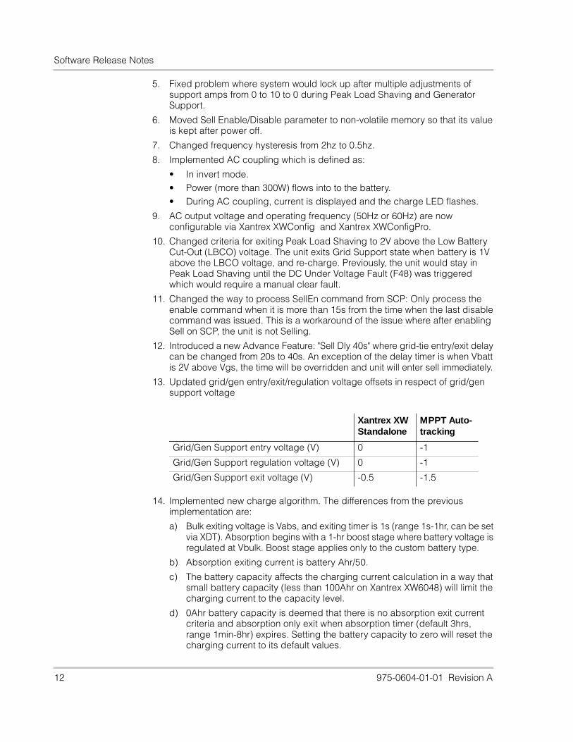
Software Release Notes
2 975-0604-01-01 Revision A
865-1000 (Xantrex XW6048-NA)
865-1000.01_03_00.BN0012
Build Range: 865-1000.01_00_00.BN0028 — 865-1000.01_03_00.BN0012
Time Range: Sept 26, 2007 — Jun 16, 2008
1. Changed the AC-Out-Over-Voltage fault level from 253V to 260V.
2. Changed the AC-Out-Under-Voltage from 108V to 100V.
3. Adjusted the generator support functionality such that the user can set their generator support amps as low as zero.
4. Adjusted the peak load shaving functionality such that the user can set their peak load shaving amps as low as zero.
5. Fixed bug where the unit was not exiting from peak load shaving and generator support based on the user settings.
6. Increased the frequency range over which the Xantrex XW can qualify an external source. 44Hz - 70Hz (was 52Hz to 68Hz).
7. Fixed problems where the Xantrex XW improperly blocked itself from charging when peak load shaving was enabled, yet we were qualified on AC2.
8. Fixed situation where forced-charge bulk signal was being incorrectly ignored.
9. Added the phase-configuration-fault ( F70 ) to protect multiunit systems in the case that an installer cross wired phase B and phase C ( 3-phase system).
10. Added a wiring protection for 3-phase multi-unit systems. The system will issue a fault if phase B and phase C wired in reverse.
11. Fixed a preferred-source issue with multi-unit functionality. Prior to fix a system could sit indefinitely in an inverting state despite there being a valid AC source.
12. Adjusted F69 such that it is auto-escalating. It was previously a manual fault, which meant that the user had to take action when it occurred. However, false trips were detected in the field and to respond to customer concerns the fault behavior was changed.
13. Added a time-to-clear counter on the DUI for the user to see how long they have to wait before they can sell power back to the grid.
14. Fixed bug with the equalization functionality. Ensured that this functionality was blocked in the case that the user had disabled the charger.
15. Updated to the latest Xantrex Xanbus™ release.
16. Added support for 3-phase multi-unit operation.
865-1000.01_05_00.BN0011
Build number range: 1.3.0BN12 — 1.5.0BN11
Time range: June 16, 2008 — Aug 17, 2009
1. Fixed problem where system would lock up after multiple adjustments of support amps from 0 to 10 to 0 during Peak Load Shaving and Generator Support.
2. Moved Sell Enable/Disable parameter to non-volatile memory so that its value is kept after power off.
Software Release Notes
975-0604-01-01 Revision A 3
3. Changed frequency hysteresis from 2hz to 0.5hz.
4. Changed minimum breaker size to 3A.
5. Implemented AC coupling which is defined as:
• In invert mode• Power (more than 300W) flows into the battery • During AC coupling, current is displayed and the charge LED flashes.
6. AC output voltage and operating frequency (50Hz or 60Hz) are now configurable via Xantrex XWConfig and Xantrex XWConfigPro.
7. Changed criteria for exiting Peak Load Shaving to 2V above the Low Battery Cut-Out (LBCO) voltage. The unit exits Grid Support state when battery is 1V above the LBCO voltage, and re-charge. Previously, the unit would stay in Peak Load Shaving until the DC Under Voltage Fault (F48) was triggered which would require a manual clear fault.
8. Introduced a new Advance Feature: "Sell Dly 40s" where grid-tie entry/exit delay can be changed from 20s to 40s. An exception of the delay timer is when Vbatt is 2V above Vgs, the time will be overridden and unit will enter sell immediately.
9. Updated grid/gen entry/exit/regulation voltage offsets in respect of grid/gen support voltage.
10. Implemented new charge algorithm. The differences from the previous implementation are:
a) Bulk exiting voltage is Vabs, and exiting timer is 1s (range 1s-1hr, can be set via XDT). Absorption begins with a 1-hr boost stage where battery voltage is regulated at Vbulk. Boost stage applies only to the custom battery type.
b) Absorption exiting current is battery Ahr/50.
c) The battery capacity affects the charging current calculation in a way that small battery capacity (less than 100Ahr on Xantrex XW6048) will limit the charging current to the capacity level.
d) 0Ahr battery capacity is deemed that there is no absorption exit current criteria and absorption only exit when absorption timer (default 3hrs, range 1min-8hr) expires. Setting the battery capacity to zero will reset the charging current to its default values.
e) Vbulk and Vabs settings are now independent from each other on SCP.
f) Minimum charge percentage is now 5%.
g) Xantrex XW only waits for other Xantrex XW units to finish absorption before exiting the absorption stage itself. It will not wait for any other types of devices, but to exit absorption on its own.
11. The minimum load level to report on all AC ports now is 25W
Xantrex XW Standalone
MPPT Auto-tracking
Grid/Gen Support entry voltage (V) 0 -1
Grid/Gen Support regulation voltage (V) 0 -1
Grid/Gen Support exit voltage (V) -0.5 -1.5
Software Release Notes
4 975-0604-01-01 Revision A
12. Changed battery temperature compensation during charge from 10°C-40°C to 0°C-50°C
13. Implemented the "GEN SUPP PLUS" feature for the split-phase models. This feature can be enabled via SCP. It is disabled by default. This feature allows the neutral relay to be closed immediately upon detecting an AC over voltage (above 300V L1-L2). This is an attempt to balance L1-N and L2-N voltage to protect the loads when AC inputs disconnect suddenly while the unit was powering an unbalanced load. This feature helps with generators that are less than 5kW.
14. Improved charge voltage regulation in a multiunit installation where more than one unit is charging a Gel type battery bank. Previously, the battery bank can be over-charged and damaged due to the low impedance present in the Gel type batteries.
15. Changed the fault-set hysteresis to 0V for F48 (DC under voltage fault) to prevent premature fault triggering. Also changed default fault level to 46V/23V, and recovery hysteresis to 4V/2V.
16. In order to prevent passive charging, added protection to not qualify AC if DC voltage is below 40V for 48V system or 20V for 24V system.
17. Added protection to put unit into sleep mode if the DC voltage is below V-LBCO for more than 24hrs to prevent draining the batteries.
18. Changed the battery over temperature fault level from 70°C to 60°C.
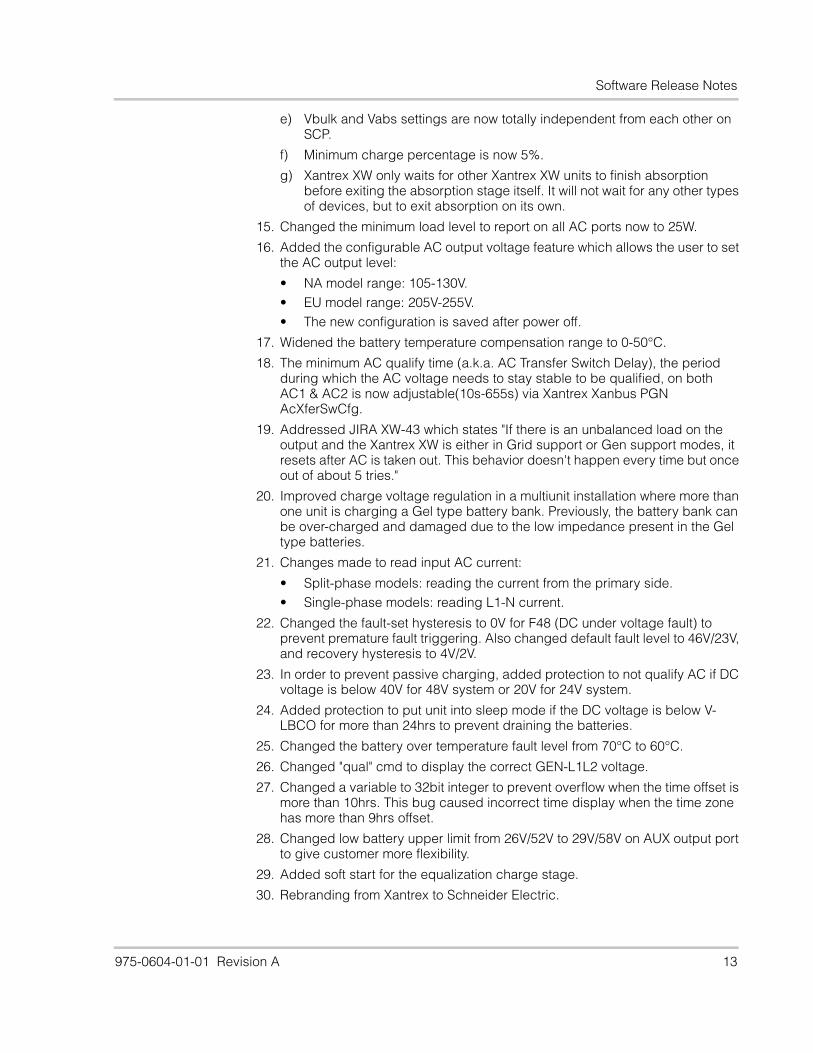
865-1000.01_07_00.BN0003
Build number range: 1.5.0BN11 — 1.7.0BN3
Time range: Aug 17, 2009 — July 15, 2010
1. Changes made to read input AC current:
• Split-phase models: reading the current from the primary side.• Single-phase models: reading L1-N current.
2. Corrected "qual" cmd to display the correct GEN-L1L2 voltage.
3. Changed low battery upper limit from 26V/52V to 29V/58V on AUX output port to give customer more flexibility.
4. Added soft start for the equalization charge stage.
5. Rebranding from Xantrex to Schneider Electric format.
6. Changed "FREQ" cmd so that it now accepts decimal frequency settings such as "55.15Hz".
7. Changed AC coupling frequency push limits down to -5Hz.
8. Made phase_error and period_error limits to be configurable via "sync" cmd. Defaults updated to phase=6(12°), period=250(≈ 2%).Syntax:SYNC return the latest readings and current limitsSYNC S # # is a number between 3 and 20. set the new phase limitSYNC D # # is a number between 15 and 1500. set the new period limit
9. Changes made so that reconfigured AC output voltage is saved after DC power cycle.
10. Fixed an issue where a unit may be unable to come back on after powering off through pressing the power button. This issue only happens in multi-unit setups where the other unit(s) is supplying the Xantrex Xanbus network power.
Software Release Notes
975-0604-01-01 Revision A 5
865-1005 (Xantrex XW4548-NA)
865-1005.01_04_00.BN0015
Build number range: 1.0.0BN10 — 1.4.0BN15
Time range: Dec 13, 2007 — Dec 19, 2008
1. Started to use local time for all activities except logging where UTC is still used. (PRN5976)
2. Implemented AC coupling which is defined as:
• In invert mode.• Power (more than 300W) flows into the battery.• During AC coupling, current is displayed and the charge LED flashes.
3. Changed criteria for exiting Peak Load Shaving to 2V above the Low Battery Cut-Out (LBCO) voltage, and recharging while in Grid Support state to 1V above the LBCO voltage. Previously, the unit would stay in Peak Load Shaving until the DC Under Voltage Fault (F48) is triggered which would require a manual clear fault.
4. AC output voltage and operating frequency (50Hz or 60Hz) are now configurable via Xantrex XWConfig and Xantrex XWConfigPro.
5. Moved Sell Enable/Disable parameter to non-volatile memory so that its value is kept after power off.
6. Modified multi-unit AC qualification so that the master temporarily changes its preferred AC source to allow transfer to the other source if all system units have the potential to qualify the other source and one or more units cannot qualify the preferred source.
7. Addressed an issue where an overloaded 3 phase system could cause cross talk on the other side of an open relay. This phantom signal was detected and misinterpreted as a real signal. When this signal was analyzed the system would interpret it as an AC source that was mis-wired (phase B where phase C should have been). This misinterpretation causes the unit to issue a F70, or a phase configuration fault. To fix this problem, the code that caused the phase configuration fault was adjusted to determine if the signal was real, by ensuring that its magnitude was greater than the AC qualification threshold.
8. Changed F69 (Sync fail) to be auto-escalating. An auto escalating fault is a hybrid fault. It acts like an automatic fault until a certain number of faults are cleared within a certain period of time. If the fault is occurring and clearing often enough, the fault behavior changes and the unit turns off until the user fixes the problem. An advanced user can query any fault or warning on the system to determine how that fault table is configured.
9. Fixed bug with the equalization functionality. Ensured that this functionality was blocked in the case that the user had disabled the charger.
10. Fixed multi-unit load staggering problem, so that only one slave unit turns on when there is a load that exceeds 60% of the rated load. Before, all slave units would turn on but the extra unit eventually turns off.
11. Changed warning 70 into fault 70 (phase configuration fault).
12. Eliminated fault, warning and event log entries with "Time N/A" stamp.
Software Release Notes
6 975-0604-01-01 Revision A
13. Fixed incorrect power calculation for AC Gen L1.
14. Disabled SINEGEN sync functionality on hibernate.
15. Fixed problem where system would lock up after multiple adjustments of support amps from 0 to 10 to 0 during Peak Load Shaving and Generator Support.
16. Fixed Xantrex Xantrex XW Slave units exhibit Invert delay on Transfer. Now if Search Mode is disabled, slave units will automatically start to invert on AC fail instead of waiting for instruction from master.
17. Adjusted code to issue W70 regardless of the state.
18. Added timer display when the system is in the Anti-Islanding timeout window. Anti-Islanding timeout window is the time the system takes to resume normal task after it recovers from an A.I. fault.
19. Changes made to re-issue faults upon entering the invert or charge mode to stop the unit from entering these modes if a fault is active.
20. Changes made to start/stop Peak Load Shaving if the time window is changed.
21. Changed the minimum AC load to be displayed as 25W. Readings less than 25W would be shown as zero.
22. Fixed bug where a negative power reading might result an incorrect calculated power display on SCP during invert.
23. Changed the DC Over Voltage fault to be a power conversion fault, so that the invert state cannot be engaged when the fault is active.
24. Changed Line-to-Neutral Over Voltage reconnect voltage to 127.2V (in Sell mode).
25. Widened operating frequency range to 59.3-60.5Hz (in Sell mode).
26. Added RPO (Remote Power Off) and NLVD (No Load Voltage Derating) features.
865-1005.01_07_00.BN0003
Build number range: 1.4.0BN15 — 1.7.0BN3
Time range: Dec 19, 2008 — July 27, 2010
1. Introduced a new Advance Feature: "Sell Dly 40s" where grid-tie entry/exit delay can be changed from 20s to 40s. An exception of the delay timer is when Vbatt is 2V above Vgs, the time will be overridden and unit will enter sell immediately.
2. Updated grid/gen entry/exit/regulation voltage offsets in respect of grid/gen support voltage
Xantrex XW Standalone
MPPT Auto-tracking
Grid/Gen Support entry voltage (V) 0 -1
Grid/Gen Support regulation voltage (V) 0 -1
Grid/Gen Support exit voltage (V) -0.5 -1.5
Software Release Notes
975-0604-01-01 Revision A 7
3. Implemented new charge algorithm. The differences from the previous implementation are:
a) Bulk exiting voltage is Vabs, and exiting timer is 1s (range 1s-1hr, can be set via XDT). Absorption begins with a 1-hr boost stage where battery voltage is regulated at Vbulk. Boost stage applies only to the custom battery type.
b) Absorption exiting current is battery Ahr/50.
c) The battery capacity affects the charging current calculation in a way that small battery capacity (less than 100Ahr on Xantrex XW6048) will limit the charging current to the capacity level.
d) 0Ahr battery capacity is deemed that there is no absorption exit current criteria and absorption only exit when absorption timer (default 3hrs, range 1min-8hr) expires. Setting the battery capacity to zero will reset the charging current to its default values.
e) Vbulk and Vabs settings are now totally independent from each other on SCP.
f) Minimum charge percentage is now 5%.
g) Xantrex XW only waits for other Xantrex XW units to finish absorption before exiting the absorption stage itself. It will not wait for any other types of devices, but to exit absorption on its own.
4. The minimum load level to report on all AC ports now is 25W.
5. Implemented the "GEN SUPP PLUS" feature for the split-phase models. This feature can be enabled via SCP. It is disabled by default. This feature allows the neutral relay to be closed immediately upon detecting an AC over voltage (above 300V L1-L2). This is an attempt to balance L1-N and L2-N voltage to protect the loads when AC inputs disconnect suddenly while the unit was powering an unbalanced load. This feature helps with generators that are less than 5kW.
6. Changes made to read input AC current:
• Split-phase models: reading the current from the primary side.• Single-phase models: reading L1-N current.
7. Changed the fault-set hysteresis to 0V for F48 (DC under voltage fault) to prevent premature fault triggering. Also changed default fault level to 46V/23V, and recovery hysteresis to 4V/2V.
8. In order to prevent passive charging, added protection to not qualify AC if DC voltage is below 40V for 48V system or 20V for 24V system.
9. Added protection to put unit into sleep mode if the DC voltage is below V-LBCO for more than 24hrs to prevent draining the batteries.
10. Changed the battery over temperature fault level from 70°C to 60°C.
11. Corrected "qual" cmd to display the correct GEN-L1L2 voltage.
12. Changed low battery upper limit from 26V/52V to 29V/58V on AUX output port to give customer more flexibility.
13. Added soft start for the equalization charge stage.
14. Rebranding from Xantrex to Schneider Electric format.
15. Changed "FREQ" cmd so that it now accepts decimal frequency settings such as "55.15Hz".
Software Release Notes
8 975-0604-01-01 Revision A
16. Changed AC coupling frequency push limits down to -5Hz.
17. Made phase_error and period_error limits to be configurable via "sync" cmd. Defaults updated to phase=6(12°), period=250(≈ 2%).Syntax:SYNC return the latest readings and current limitsSYNC S # # is a number between 3 and 20. set the new phase limitSYNC D # # is a number between 15 and 1500. set the new period limit
18. Changes made so that reconfigured AC output voltage is saved after DC power cycle.
19. Fixed an issue where a unit may be unable to come back on after powering off through pressing the power button. This issue only happens in multi-unit setups where the other unit(s) is supplying the Xantrex Xanbus network power.
865-1010 (Xantrex XW4024-NA)
865-1010.01_04_00.BN0002
Build number range: 1.0.0BN18 — 1.4.0BN2
Time range: Sept 13, 2007 — Sept 25, 2008
1. Changed Line-to-Neutral Over Voltage reconnect voltage to 127.2 V (in Sell mode).
2. Widened operating frequency range to 59.3-60.5 Hz (in Sell mode).
3. Started to use local time for all activities except logging where UTC is still used.
4. Modified multi-unit AC qualification so that the master temporarily changes its preferred AC source to allow transfer to the other source if all system units have the potential to qualify the other source and one or more units cannot qualify the preferred source.
5. Added RPO (Remote Power Off) and NLVD (No Load Voltage Derating) features.
6. Addressed an issue where an overloaded 3 phase system could cause cross talk on the other side of an open relay. This phantom signal was detected and misinterpreted as a real signal. When this signal was analyzed the system would interpret it as an AC source that was mis-wired (phase B where phase C should have been). This mis-interpretation causes the unit to issue a F70, or a phase configuration fault. To fix this problem, the code that caused the phase configuration fault was adjusted to determine if the signal was real, by ensuring that its magnitude was greater than the AC qualification threshold.
7. Changed the DC Over Voltage fault to be a power conversion fault, so that the invert state cannot be engaged when the fault is active.
8. Fixed bug with the equalization functionality. Ensured that this functionality was blocked in the case that the user had disabled the charger.
9. Fixed multi-unit load staggering problem, so that only one slave unit turns on when there is a load that exceeds 60% of the rated load. Before, all slave units would turn on but the extra unit eventually turns off.
Software Release Notes
975-0604-01-01 Revision A 9
10. Changed warning 70 into fault 70 ( phase configuration fault).
11. Eliminated fault, warning and event log entries with "Time N/A" stamp.
12. Added timer display when the system is in the Anti-Islanding timeout window. Anti-Islanding timeout window is the time the system takes to resume normal task after it recovers from an A.I. fault.
13. Fixed Xantrex XW Slave units exhibit Invert delay on Transfer.Now if Search Mode is disabled, slave units will automatically start to invert on AC fail instead of waiting for instruction from master.
14. Fixed bug where a negative power reading might result an incorrect calculated power display on SCP during invert.
15. Moved Sell Enable/Disable parameter to non-volatile memory so that its value kept after power off.
16. Fixed incorrect power calculation for AC Gen L1.
17. Changed F69 (Sync fail) to be auto-escalating. An auto escalating fault is a hybrid fault. It acts like an automatic fault until a certain number of faults are cleared within a certain period of time. If the fault is occurring and clearing often enough, the fault behavior changes and the unit turns off until the user fixes the problem. An advanced user can query any fault or warning on the system to determine how that fault table is configured.
18. Disabled SINEGEN sync functionality on hibernate (PRN5835).
19. Fixed problem where system would lock up after multiple adjustments of support amps from 0 to 10 to 0 during Peak Load Shaving and Generator Support.
20. Adjusted code to issue W70 regardless of the state.
21. Changed to shut off the other units when one unit shuts off during invert in a three-phase system.
22. Changed code to start/stop Peak Load Shaving if the time window is changed.
865-1010.01_07_00.BN0003
Build number range: 1.4.0BN2 — 1.7.0 BN3
Time range: Sept 25, 2008 — July 15, 2010
1. Implemented AC coupling which is defined as:
• In invert mode.• But power (more than 300W) flows into to the battery. • During AC coupling, current is displayed and the charge LED flashes.
2. AC output voltage and operating frequency (50Hz or 60Hz) are now configurable via Xantrex XWConfig and Xantrex XWConfigPro.
3. Changed criteria for exiting Peak Load Shaving to 2V above the Low Battery Cut-Out (LBCO) voltage. The unit exits Grid Support state when battery is 1V above the LBCO voltage, and re-charge. Previously, the unit would stay in Peak Load Shaving until the DC Under Voltage Fault (F48) was triggered which would require a manual clear fault.
Software Release Notes
10 975-0604-01-01 Revision A
4. Updated grid/gen entry/exit/regulation voltage offsets in respect of grid/gen support voltage.
5. Implemented new charge algorithm. The differences from the previous implementation are:
a) Bulk exiting voltage is Vabs, and exiting timer is 1s (range 1s-1hr, can be set via XDT). Absorption begins with a 1-hr boost stage where battery voltage is regulated at Vbulk. Boost stage applies only to the custom battery type.
b) Absorption exiting current is battery Ahr/50.
c) The battery capacity affects the charging current calculation in a way that small battery capacity (less than 100Ahr on Xantrex XW6048) will limit the charging current to the capacity level.
d) 0Ahr battery capacity is deemed that there is no absorption exit current criteria and absorption only exit when absorption timer (default 3hrs, range 1min-8hr) expires. Setting the battery capacity to zero will reset the charging current to its default values.
e) Vbulk and Vabs settings are now totally independent from each other on SCP.
f) Minimum charge percentage is now 5%.
g) Xantrex XW only waits for other Xantrex XW units to finish absorption before exiting the absorption stage itself. It will not wait for any other types of devices, but to exit absorption on its own.
6. The minimum load level to report on all AC ports now is 25W.
7. Implemented the "GEN SUPP PLUS" feature for the split-phase models. This feature can be enabled via SCP. It is disabled by default. This feature allows the neutral relay to be closed immediately upon detecting an AC over voltage (above 300V L1-L2). This is an attempt to balance L1-N and L2-N voltage to protect the loads when AC inputs disconnect suddenly while the unit was powering an unbalanced load. This feature helps with generators that are less than 5kW.
8. Improved charge voltage regulation in a multiunit installation where more than one unit is charging a Gel type battery bank. Previously, the battery bank can be over-charged and damaged due to the low impedance present in the Gel type batteries.
9. Changes made to read input AC current:
• Split-phase models: reading the current from the primary side.• Single-phase models: reading L1-N current.
Xantrex XW Standalone
MPPT Auto-tracking
Grid/Gen Support entry voltage (V) 0 -1
Grid/Gen Support regulation voltage (V) 0 -1
Grid/Gen Support exit voltage (V) -0.5 -1.5
Software Release Notes
975-0604-01-01 Revision A 11
10. Changed the fault-set hysteresis to 0V for F48 (DC under voltage fault) to prevent premature fault triggering. Also changed default fault level to 46V/23V, and recovery hysteresis to 4V/2V.
11. In order to prevent passive charging, added protection to not qualify AC if DC voltage is below 40V for 48V system or 20V for 24V system.
12. Added protection to put unit into sleep mode if the DC voltage is below V-LBCO for more than 24hrs to prevent draining the batteries.
13. Changed the battery over temperature fault level from 70°C to 60°C.
14. Corrected "qual" cmd to display the correct GEN-L1L2 voltage.
15. Changed low battery upper limit from 26V/52V to 29V/58V on AUX output port to give customer more flexibility.
16. Added soft start for the equalization charge stage.
17. Rebranding from Xantrex to Schneider Electric format.
18. Changed "FREQ" cmd so that it now accepts decimal frequency settings such as "55.15Hz".
19. Changed AC coupling frequency push limits down to -5Hz.
20. Made phase_error and period_error limits to be configurable via "sync" cmd. Defaults updated to phase=6(12°), period=250(≈ 2%).Syntax:SYNC return the latest readings and current limitsSYNC S # # is a number between 3 and 20. set the new phase limitSYNC D # # is a number between 15 and 1500. set the new period limit
21. Changes made so that reconfigured AC output voltage is saved after DC power cycle.
22. Fixed an issue where a unit may be unable to come back on after powering off through pressing the power button. This issue only happens in multi-unit setups where the other unit(s) is supplying the Xantrex Xanbus network power.
865-1035 (Xantrex XW6048-EU)
865-1035.01_07_00.BN0005
Build number range: 1.0.0BN29 — 1.7.0BN4
Time range: Apr 21, 2008 — June 16, 2010
1. Fixed Xantrex XW Slave units exhibit Invert delay on Transfer. Now if Search Mode is disabled, slave units will automatically start to invert on AC fail instead of waiting for instruction from master.
2. Changed the SHORT_CIRCUIT_CHECK_TIMES from 30 to 120 to change the short circuit time from 250ms to 1ms at 60Hz.
3. Added rated power derating in charge current calculation.
4. Added hysteresis to address the oscillation issue occurring between grid-support (or gen support) and peak-load-shaving states when unit is not precisely calibrated.
Software Release Notes
12 975-0604-01-01 Revision A
5. Fixed problem where system would lock up after multiple adjustments of support amps from 0 to 10 to 0 during Peak Load Shaving and Generator Support.
6. Moved Sell Enable/Disable parameter to non-volatile memory so that its value is kept after power off.
7. Changed frequency hysteresis from 2hz to 0.5hz.
8. Implemented AC coupling which is defined as:
• In invert mode.• Power (more than 300W) flows into to the battery.• During AC coupling, current is displayed and the charge LED flashes.
9. AC output voltage and operating frequency (50Hz or 60Hz) are now configurable via Xantrex XWConfig and Xantrex XWConfigPro.
10. Changed criteria for exiting Peak Load Shaving to 2V above the Low Battery Cut-Out (LBCO) voltage. The unit exits Grid Support state when battery is 1V above the LBCO voltage, and re-charge. Previously, the unit would stay in Peak Load Shaving until the DC Under Voltage Fault (F48) was triggered which would require a manual clear fault.
11. Changed the way to process SellEn command from SCP: Only process the enable command when it is more than 15s from the time when the last disable command was issued. This is a workaround of the issue where after enabling Sell on SCP, the unit is not Selling.
12. Introduced a new Advance Feature: "Sell Dly 40s" where grid-tie entry/exit delay can be changed from 20s to 40s. An exception of the delay timer is when Vbatt is 2V above Vgs, the time will be overridden and unit will enter sell immediately.
13. Updated grid/gen entry/exit/regulation voltage offsets in respect of grid/gen support voltage
14. Implemented new charge algorithm. The differences from the previous implementation are:
a) Bulk exiting voltage is Vabs, and exiting timer is 1s (range 1s-1hr, can be set via XDT). Absorption begins with a 1-hr boost stage where battery voltage is regulated at Vbulk. Boost stage applies only to the custom battery type.
b) Absorption exiting current is battery Ahr/50.
c) The battery capacity affects the charging current calculation in a way that small battery capacity (less than 100Ahr on Xantrex XW6048) will limit the charging current to the capacity level.
d) 0Ahr battery capacity is deemed that there is no absorption exit current criteria and absorption only exit when absorption timer (default 3hrs, range 1min-8hr) expires. Setting the battery capacity to zero will reset the charging current to its default values.
Xantrex XW Standalone
MPPT Auto-tracking
Grid/Gen Support entry voltage (V) 0 -1
Grid/Gen Support regulation voltage (V) 0 -1
Grid/Gen Support exit voltage (V) -0.5 -1.5
Software Release Notes
975-0604-01-01 Revision A 13
e) Vbulk and Vabs settings are now totally independent from each other on SCP.
f) Minimum charge percentage is now 5%.
g) Xantrex XW only waits for other Xantrex XW units to finish absorption before exiting the absorption stage itself. It will not wait for any other types of devices, but to exit absorption on its own.
15. Changed the minimum load level to report on all AC ports now to 25W.
16. Added the configurable AC output voltage feature which allows the user to set the AC output level:
• NA model range: 105-130V. • EU model range: 205V-255V.• The new configuration is saved after power off.
17. Widened the battery temperature compensation range to 0-50°C.
18. The minimum AC qualify time (a.k.a. AC Transfer Switch Delay), the period during which the AC voltage needs to stay stable to be qualified, on both AC1 & AC2 is now adjustable(10s-655s) via Xantrex Xanbus PGN AcXferSwCfg.
19. Addressed JIRA XW-43 which states "If there is an unbalanced load on the output and the Xantrex XW is either in Grid support or Gen support modes, it resets after AC is taken out. This behavior doesn't happen every time but once out of about 5 tries."
20. Improved charge voltage regulation in a multiunit installation where more than one unit is charging a Gel type battery bank. Previously, the battery bank can be over-charged and damaged due to the low impedance present in the Gel type batteries.
21. Changes made to read input AC current:
• Split-phase models: reading the current from the primary side.• Single-phase models: reading L1-N current.
22. Changed the fault-set hysteresis to 0V for F48 (DC under voltage fault) to prevent premature fault triggering. Also changed default fault level to 46V/23V, and recovery hysteresis to 4V/2V.
23. In order to prevent passive charging, added protection to not qualify AC if DC voltage is below 40V for 48V system or 20V for 24V system.
24. Added protection to put unit into sleep mode if the DC voltage is below V-LBCO for more than 24hrs to prevent draining the batteries.
25. Changed the battery over temperature fault level from 70°C to 60°C.
26. Changed "qual" cmd to display the correct GEN-L1L2 voltage.
27. Changed a variable to 32bit integer to prevent overflow when the time offset is more than 10hrs. This bug caused incorrect time display when the time zone has more than 9hrs offset.
28. Changed low battery upper limit from 26V/52V to 29V/58V on AUX output port to give customer more flexibility.
29. Added soft start for the equalization charge stage.
30. Rebranding from Xantrex to Schneider Electric.
Software Release Notes
14 975-0604-01-01 Revision A
31. Changed "FREQ" cmd so that it now accepts decimal frequency settings such as "55.15Hz".
32. Changed AC coupling frequency push limits down to -5Hz.
33. Made phase_error and period_error limits to be configurable via "sync" cmd. Defaults updated to phase=6(12°), period=250(≈ 2%).Syntax:SYNC return the latest readings and current limitsSYNC S # # is a number between 3 and 20. set the new phase limitSYNC D # # is a number between 15 and 1500. set the new period limit
34. Fixed an issue where a unit may be unable to come back on after powering off through pressing the power button. This issue only happens in multi-unit setups where the other unit(s) is supplying the Xantrex Xanbus network power.
865-1040 (Xantrex XW4548-EU)
865-1040.01_07_00.BN0006
Build number range: 1.3.0BN10 — 1.7.0BN5
Time range: Aug 06, 2008 — June 16, 2010
1. Moved Sell Enable/Disable parameter to non-volatile memory so that its value is kept after power off.
2. Adjusted the A.I. bounds such that they are less aggressive. This was done to address customer complaints about how our equipment would not connect to poorly regulated utilities (which is often the case in the back up market).
3. Changed frequency hysteresis from 2hz to 0.5hz
4. Implemented AC coupling which is defined as:
• In invert mode.• But power (more than 300W) flows into to the battery. • During AC coupling, current is displayed and the charge LED flashes.
5. AC output voltage and operating frequency (50Hz or 60Hz) are now configurable via Xantrex XWConfig and Xantrex XWConfigPro.
6. Changed criteria for exiting Peak Load Shaving to 2V above the Low Battery Cut-Out (LBCO) voltage. The unit exits Grid Support state when battery is 1V above the LBCO voltage, and re-charge. Previously, the unit would stay in Peak Load Shaving until the DC Under Voltage Fault (F48) was triggered which would require a manual clear fault.
7. Changed the way to process SellEn command from SCP: Only process the enable command when it is more than 15s from the time when the last disable command was issued. This is a workaround of the issue where after enabling Sell on SCP, the unit is not Selling.
8. Introduced a new Advance Feature: "Sell Dly 40s" where grid-tie entry/exit delay can be changed from 20s to 40s. An exception of the delay timer is when Vbatt is 2V above Vgs, the time will be overridden and unit will enter sell immediately.
Software Release Notes
975-0604-01-01 Revision A 15
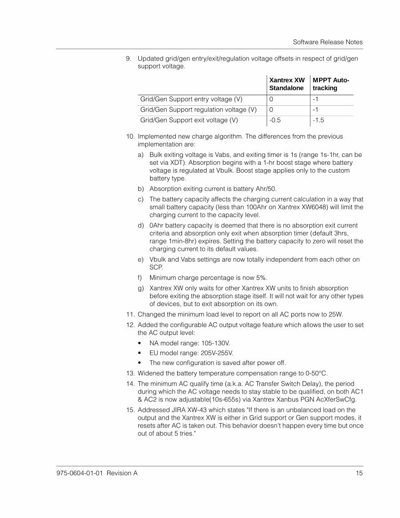
9. Updated grid/gen entry/exit/regulation voltage offsets in respect of grid/gen support voltage.
10. Implemented new charge algorithm. The differences from the previous implementation are:
a) Bulk exiting voltage is Vabs, and exiting timer is 1s (range 1s-1hr, can be set via XDT). Absorption begins with a 1-hr boost stage where battery voltage is regulated at Vbulk. Boost stage applies only to the custom battery type.
b) Absorption exiting current is battery Ahr/50.
c) The battery capacity affects the charging current calculation in a way that small battery capacity (less than 100Ahr on Xantrex XW6048) will limit the charging current to the capacity level.
d) 0Ahr battery capacity is deemed that there is no absorption exit current criteria and absorption only exit when absorption timer (default 3hrs, range 1min-8hr) expires. Setting the battery capacity to zero will reset the charging current to its default values.
e) Vbulk and Vabs settings are now totally independent from each other on SCP.
f) Minimum charge percentage is now 5%.
g) Xantrex XW only waits for other Xantrex XW units to finish absorption before exiting the absorption stage itself. It will not wait for any other types of devices, but to exit absorption on its own.
11. Changed the minimum load level to report on all AC ports now to 25W.
12. Added the configurable AC output voltage feature which allows the user to set the AC output level:
• NA model range: 105-130V.
• EU model range: 205V-255V.
• The new configuration is saved after power off.
13. Widened the battery temperature compensation range to 0-50°C.
14. The minimum AC qualify time (a.k.a. AC Transfer Switch Delay), the period during which the AC voltage needs to stay stable to be qualified, on both AC1 & AC2 is now adjustable(10s-655s) via Xantrex Xanbus PGN AcXferSwCfg.
15. Addressed JIRA XW-43 which states "If there is an unbalanced load on the output and the Xantrex XW is either in Grid support or Gen support modes, it resets after AC is taken out. This behavior doesn't happen every time but once out of about 5 tries."
Xantrex XW Standalone
MPPT Auto-tracking
Grid/Gen Support entry voltage (V) 0 -1
Grid/Gen Support regulation voltage (V) 0 -1
Grid/Gen Support exit voltage (V) -0.5 -1.5
Software Release Notes
16 975-0604-01-01 Revision A
16. Improved charge voltage regulation in a multiunit installation where more than one unit is charging a Gel type battery bank. Previously, the battery bank can be over-charged and damaged due to the low impedance present in the Gel type batteries.
17. Changes made to read input AC current:
• Split-phase models: reading the current from the primary side.• Single-phase models: reading L1-N current.
18. Changed the fault-set hysteresis to 0V for F48 (DC under voltage fault) to prevent premature fault triggering. Also changed default fault level to 46V/23V, and recovery hysteresis to 4V/2V.
19. In order to prevent passive charging, added protection to not qualify AC if DC voltage is below 40V for 48V system or 20V for 24V system.
20. Added protection to put unit into sleep mode if the DC voltage is below V-LBCO for more than 24hrs to prevent draining the batteries.
21. Changed the battery over temperature fault level from 70°C to 60°C.
22. Changed "qual" cmd to display the correct GEN-L1L2 voltage.
23. Changed low battery upper limit from 26V/52V to 29V/58V on AUX output port to give customer more flexibility.
24. Added soft start for the equalization charge stage.
25. Rebranding from Xantrex to Schneider Electric format.
26. Changed "FREQ" cmd so that it now accepts decimal frequency settings such as "55.15Hz".
27. Changed AC coupling frequency push limits down to -5Hz.
28. Made phase_error and period_error limits to be configurable via "sync" cmd. Defaults updated to phase=6(12°), period=250(≈ 2%).Syntax:SYNC return the latest readings and current limitsSYNC S # # is a number between 3 and 20. set the new phase limitSYNC D # # is a number between 15 and 1500. set the new period limit
29. Fixed an issue where a unit may be unable to come back on after powering off through pressing the power button. This issue only happens in multi-unit setups where the other unit(s) is supplying the Xantrex Xanbus network power.
865-1045 (Xantrex XW4024-EU)
865-1045.01_07_00.BN0005
Build number range: 1.3.0BN20 — 1.7.0BN4
Time range: Aug 10, 2008 — Jan 13, 2010
1. Moved Sell Enable/Disable parameter to non-volatile memory so that its value is kept after power off.
2. Adjusted the A.I. bounds such that they are less aggressive. This was done to address customer complaints about how our equipment would not connect to poorly regulated utilities (which is often the case in the back up market).
Software Release Notes
975-0604-01-01 Revision A 17
3. Changed frequency hysteresis from 2hz to 0.5hz
4. Changed minimum breaker size to 3A.
5. Implemented AC coupling which is defined as:
• In invert mode.
• But power (more than 300W) flows into to the battery.
• During AC coupling, current is displayed and the charge LED flashes.
6. AC output voltage and operating frequency (50Hz or 60Hz) are now configurable via Xantrex XWConfig (PGN AcCfg).
7. Changed criteria for exiting Peak Load Shaving to 2V above the Low Battery Cut-Out (LBCO) voltage. The unit exits Grid Support state when battery is 1V above the LBCO voltage, and re-charge.
8. Previously, the unit would stay in Peak Load Shaving until the DC Under Voltage Fault (F48) was triggered which would require a manual clear fault.
9. Changed the rate of updating Vdc value during sell mode to 2Hz so that the user should see a more stable power reading on the front panel.
10. Changed control loop update rate to 30Hz instead of 120Hz before to solve the missing charge cycle problem. (4024 was later changed back still using 120Hz update rate).
11. Changed the way to process SellEn command from SCP: Only process the enable command when it is more than 15s from the time when the last disable command was issued. This is a workaround of the issue where after enabling Sell on SCP, the unit is not Selling.
12. Introduced a new Advance Feature: "Sell Dly 40s" where grid-tie entry/exit delay can be changed from 20s to 40s. An exception of the delay timer is when Vbatt is 2V above Vgs, the time will be overridden and unit will enter sell immediately.
13. Updated grid/gen entry/exit/regulation voltage offsets in respect of grid/gen support voltage
14. Implemented new charge algorithm. The differences from the previous implementation are:
a) Bulk exiting voltage is Vabs, and exiting timer is 1s (range 1s-1hr, can be set via XDT). Absorption begins with a 1-hr boost stage where battery voltage is regulated at Vbulk. Boost stage applies only to the custom battery type.
b) Absorption exiting current is battery Ahr/50.
c) The battery capacity affects the charging current calculation in a way that small battery capacity (less than 100Ahr on Xantrex XW6048) will limit the charging current to the capacity level.
Xantrex XW Standalone
MPPT Auto-tracking
Grid/Gen Support entry voltage (V) 0 -1
Grid/Gen Support regulation voltage (V) 0 -1
Grid/Gen Support exit voltage (V) -0.5 -1.5
Software Release Notes
18 975-0604-01-01 Revision A
d) 0Ahr battery capacity is deemed that there is no absorption exit current criteria and absorption only exit when absorption timer (default 3hrs, range 1min-8hr) expires. Setting the battery capacity to zero will reset the charging current to its default values.
e) Vbulk and Vabs settings are now totally independent from each other on SCP.
f) Minimum charge percentage is now 5%.
g) Xantrex XW only waits for other Xantrex XW units to finish absorption before exiting the absorption stage itself. It will not wait for any other types of devices, but to exit absorption on its own.
15. Changed the minimum load level to report on all AC ports now to 25W.
16. Added the configurable AC output voltage feature which allows the user to set the AC output level:
• NA model range: 105-130V.
• EU model range: 205V-255V.
• The new configuration is saved after power off.
17. Widened the battery temperature compensation range to 0-50°C.
18. The minimum AC qualify time (a.k.a. AC Transfer Switch Delay), the period during which the AC voltage needs to stay stable to be qualified, on both AC1 & AC2 is now adjustable(10s-655s) via Xantrex Xanbus PGN AcXferSwCfg.
19. Addressed JIRA XW-43 which states "If there is an unbalanced load on the output and the Xantrex XW is either in Grid support or Gen support modes, it resets after AC is taken out. This behavior doesn't happen every time but once out of about 5 tries."
20. Improved charge voltage regulation in a multiunit installation where more than one unit is charging a Gel type battery bank. Previously, the battery bank can be over-charged and damaged due to the low impedance present in the Gel type batteries.
21. Changes made to read input AC current:
• Split-phase models: reading the current from the primary side.
• Single-phase models: reading L1-N current.
22. Changed the fault-set hysteresis to 0V for F48 (DC under voltage fault) to prevent premature fault triggering. Also changed default fault level to 46V/23V, and recovery hysteresis to 4V/2V.
23. In order to prevent passive charging, added protection to not qualify AC if DC voltage is below 40V for 48V system or 20V for 24V system.
24. Added protection to put unit into sleep mode if the DC voltage is below V-LBCO for more than 24hrs to prevent draining the batteries.
25. Changed the battery over temperature fault level from 70°C to 60°C.
26. Changed "qual" cmd to display the correct GEN-L1L2 voltage.
27. Changed low battery upper limit from 26V/52V to 29V/58V on AUX output port to give customer more flexibility.
28. Added soft start for the equalization charge stage.
Software Release Notes
975-0604-01-01 Revision A 19
29. Changed "FREQ" cmd so that it now accepts decimal frequency settings such as "55.15Hz".
30. Changed AC coupling frequency push limits down to -5Hz.
31. Made phase_error and period_error limits to be configurable via "sync" cmd. Defaults updated to phase=6(12°), period=250(≈ 2%).Syntax:SYNC return the latest readings and current limitsSYNC S # # is a number between 3 and 20. set the new phase limitSYNC D # # is a number between 15 and 1500. set the new period limit
32. Fixed an issue where a unit may be unable to come back on after powering off through pressing the power button. This issue only happens in multi-unit setups where the other unit(s) is supplying the Xantrex Xanbus network power.
Software Release Notes
20 975-0604-01-01 Revision A
865-1030 (Xantrex XW MPPT Charge Controller)
865-1030.01_05_00.BN0006
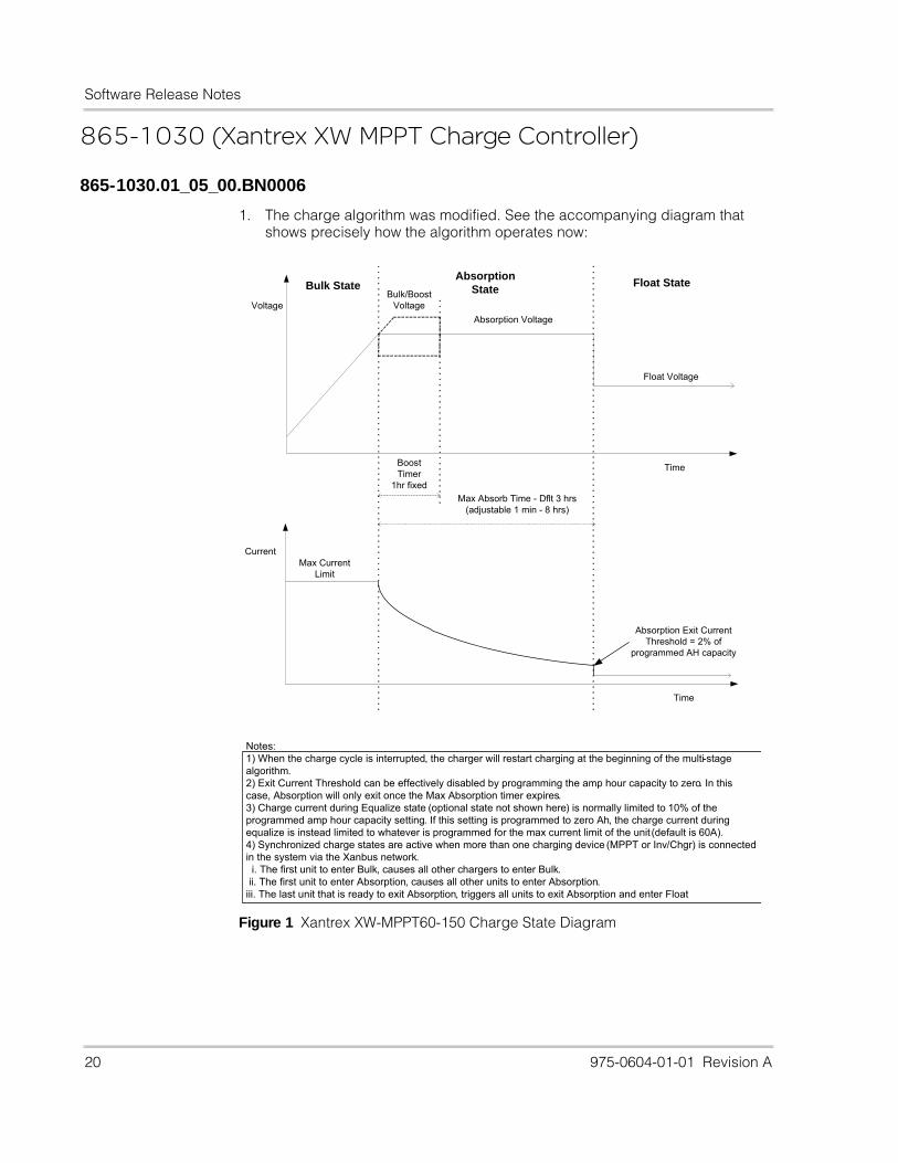
1. The charge algorithm was modified. See the accompanying diagram that shows precisely how the algorithm operates now:
Figure 1 Xantrex XW-MPPT60-150 Charge State Diagram
Notes: 1) When the charge cycle is interrupted, the charger will restart charging at the beginning of the multi-stage algorithm. 2) Exit Current Threshold can be effectively disabled by programming the amp hour capacity to zero. In this case, Absorption will only exit once the Max Absorption timer expires.3) Charge current during Equalize state (optional state not shown here) is normally limited to 10% of the programmed amp hour capacity setting. If this setting is programmed to zero Ah, the charge current during equalize is instead limited to whatever is programmed for the max current limit of the unit (default is 60A).4) Synchronized charge states are active when more than one charging device (MPPT or Inv/Chgr) is connected in the system via the Xanbus network. i. The first unit to enter Bulk, causes all other chargers to enter Bulk. ii. The first unit to enter Absorption, causes all other units to enter Absorption.iii. The last unit that is ready to exit Absorption, triggers all units to exit Absorption and enter Float
Float StateAbsorption
StateBulk State
Current
Time
Max Current Limit
Voltage
Time
Absorption Voltage
Float Voltage
Max Absorb Time - Dflt 3 hrs (adjustable 1 min - 8 hrs)
Bulk/Boost Voltage
Boost Timer
1hr fixed
Absorption Exit Current Threshold = 2% of
programmed AH capacity
Software Release Notes
975-0604-01-01 Revision A 21
2. Improvements were made to the Xantrex Xanbus library to make the device more robust on the CAN network in the presence of network errors. The unit no longer resets itself at midnight, which was a temporary fix to the problem of corrupted network communications. It will now detect any network corruption and perform a soft reset of the Xantrex Xanbus functionality only, if a corruption occurs.
3. A new feature was added to provide float time information to the user. Two new home/status screens are available when the unit is either in Float or not charging. One screen shows the time that the unit last entered float at, and the other screen shows the duration of time that the unit spent in float that day. These new screens will scroll if scrolling is enabled. The screens are hidden if the charger is in Bulk, Absorption, or Equalize as the information would not be relevant.
4. A simple fix (component value change) was made for the BTS to improve the measurement circuits' immunity to switching noise on the DSP control board. This minor hardware change allows us to set the minimum BTS temperature reading to -35degC (previously we limited it to -20degC). Temperatures below this threshold are interpreted as BTS Not Connected, and the value inserted into the Temp field of the BattSts2 PGN on Xantrex Xanbus will be "reserved". The minimum temperature threshold is now dependent on the hardware version of the DSP control board. Currently, the control board is being shipped at Rev 3. The boards version will be rev'd to version 4 (by modifying a voltage divider circuit sampled by the ADC), so the -35degC limit will apply to version 4, and the old limit of -20degC will still apply if the hardware is rev 3 or older.
5. A minor bug was found where if the LocalOffsetMinutes field in the DateTimeSts PGN was set to an invalid value (ie. PGN_SI_NO_DATA), this offset still got applied when converting UTC time to local time. This invalid value scenario should not occur normally, but if it does, this new firmware build will ignore that field and set local time equal to the reported UTC time. It ensures that the local offset is within +/- 12 hours (or +/- 720 minutes) before applying it to the local time value.
6. The reset to factory default feature was triggering a bug that caused some memory locations to be corrupted as they were over written due to an array operation that went beyond the end of the array. The result of this bug was benign as the unit reset shortly after being triggered. This bug was fixed though in this version of firmware.
7. The restart pending timeout was set to 5 minutes instead of 3 minutes.
Software Release Notes
22 975-0604-01-01 Revision A
Schneider Electric, the Schneider Electric logo, Xanbus and Xantrex are trademarks or registered trademarks of the Schneider Electric group of companies. Other trademarks, registered trademarks, and product names are the property of their respective owners and are used herein for identification purposes only.Copyright © December 2010 Xantrex Technology Inc. All rights reserved. No part of this document may be reproduced in any form or disclosed to third parties without the express written consent of: Xantrex Technology Inc. 161-G South Vasco Road Livermore, California USA 94551Xantrex Technology Inc. reserves the right to revise this document and to periodically make changes to the content hereof without obligation or organization of such revisions or changes unless required to do so by prior arrangement.All warranty, disclaimer and safety information is contained within the primary documentation received with the unit. Unless specified, safety, installation, operation and specification information is as shown in the primary documentation. Ensure you are familiar with that information before proceeding.
Exclusion for DocumentationUNLESS SPECIFICALLY AGREED TO IN WRITING, XANTREX TECHNOLOGY INC. (“XANTREX”)(A) MAKES NO WARRANTY AS TO THE ACCURACY, SUFFICIENCY OR SUITABILITY OF ANY TECHNICAL OR OTHER INFORMATION PROVIDED IN ITS MANUALS OR OTHER DOCUMENTATION; (B)ASSUMES NO RESPONSIBILITY OR LIABILITY FOR LOSSES, DAMAGES, COSTS OR EXPENSES, WHETHER SPECIAL, DIRECT, INDIRECT, CONSEQUENTIAL OR INCIDENTAL, WHICH MIGHT ARISE OUT OF THE USE OF SUCH INFORMATION. THE USE OF ANY SUCH INFORMATION WILL BE ENTIRELY AT THE USER’S RISK; AND (C)REMINDS YOU THAT IF THIS DOCUMENTATION IS IN ANY LANGUAGE OTHER THAN ENGLISH, ALTHOUGH STEPS HAVE BEEN TAKEN TO MAINTAIN THE ACCURACY OF THE TRANSLATION, THE ACCURACY CANNOT BE GUARANTEED. APPROVED XANTREX CONTENT IS CONTAINED WITH THE ENGLISH LANGUAGE VERSION WHICH IS POSTED AT www.schneider-electric.com.
Date and RevisionDecember 2010 Revision A Part Number 975-0604-01-01
Contact Informationwww.schneider-electric.com
☎ ✉
North America 1 650 351 82371 866 519 1470
1 925 245 1022 [email protected]
France 0 825 012 999 [email protected]
Deutschland +49 (0) 180 575 3 575 +49 (0) 2102 404 7101 [email protected]
España +34 902 101813 +34 93 305 5026 [email protected]
Italia +39 035 4151111 +39 035415 3200 [email protected]
For other country details please contact your local Schneider Electric Sales Representative or visit our website at:http://www.schneider-electric.com/sites/corporate/en/support/operations/local-operations/local-operations.page